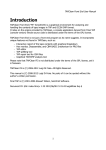
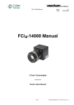
1
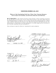
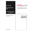
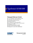
Artisan Technology Group is your source for quality
new and certified-used/pre-owned equipment
• FAST SHIPPING AND
DELIVERY
• TENS OF THOUSANDS OF
IN-STOCK ITEMS
• EQUIPMENT DEMOS
• HUNDREDS OF
MANUFACTURERS
SUPPORTED
• LEASING/MONTHLY
RENTALS
• ITAR CERTIFIED
SECURE ASSET SOLUTIONS
SERVICE CENTER REPAIRS
Experienced engineers and technicians on staff
at our full-service, in-house repair center
WE BUY USED EQUIPMENT
Sell your excess, underutilized, and idle used equipment
We also offer credit for buy-backs and trade-ins
www.artisantg.com/WeBuyEquipment
InstraView REMOTE INSPECTION
LOOKING FOR MORE INFORMATION?
Visit us on the web at www.artisantg.com for more
information on price quotations, drivers, technical
specifications, manuals, and documentation
SM
Remotely inspect equipment before purchasing with
our interactive website at www.instraview.com
Contact us: (888) 88-SOURCE | [email protected] | www.artisantg.com
DMC-300-10 DC MOTOR CONTROLLER
User's Manual (June 1988)
TABLE OF CONTENTS :
1. Overview
2. Getting Started
2.1. System Elements
2.2. Connecting the Elements
2.3. Design Examples
3. System Compensation
4. Communication
4.1. Handshake
4.2. Address Selection
5. Instruction Set
6. Modes of Motion
6.1. Profiled Positioning
6.2. Incremental Mode
6.3. Velocity Mode
7. Special Modes of operation
7.1. Local Mode
7.2. Position Latch
7.3. Stop from Run
7.4. Repeat Mode
7.5. Find Edge
Artisan Technology Group - Quality Instrumentation ... Guaranteed | (888) 88-SOURCE | www.artisantg.com
8 . Error Handling
Appendices:
A. Decimal to Hex Conversion
B. Pulse Width Modulation
C. Jumpers
D. Pin-Out
E. Pin Description
I. Noise Considerations
1. OVERVIEW
The DMC-300 series is a VME bus compatible motion controller for 1,2 or 3 DC motors. The DMC-300
controls one axis, the DMC-320 and DMC330 control two and three axes. Each product is configured as
a VMr'_ bus-compatible I/0 card.
As a true general-purpose controller, the DMC-300 series can operate in numerous modes including
point-to-point positioning and jogging. Several commands are provided including instructions for
specifying the motor position, velocity and acceleration. The motion generated is along trapezoidal
velocity profiles, and the velocity level can be changed on-the-fly.
For each axis controlled, the DMC-300 accepts position feedback from an incremental encoder. No
additional velocity feedback is required because the controller implements a digital filter for stability.
The coefficients of the filter are programmable, allowing for optimum dynamic performance.
For each axis, the DMC-300 produces a +10 volt range analog output which is input to a power
amplifier of any size.
NOTE: This manual will refer to all products in the DMC-300 series as the DMC-300. The DMC-300,
DMC-320, DMC-330 specific features will be noted where needed.
2. GETTING STARTED
2.1. System Elements
Before you start, you must get all the necessary elements. These include:
1. DMC-300 Series controller
Artisan Technology Group - Quality Instrumentation ... Guaranteed | (888) 88-SOURCE | www.artisantg.com
2. DC Motor with 2-channel incremental encoder for each axis
3. Motor driver for each axis
4. Power supply for drivers
5. VME Bus power supply for controller (+5V, +12V, -12V)
6. Host computer
7. Cable Set CC-3 (I/O cables)
Helpful but not necessary
8. ICB-930 interconnect board for each axis
9. DMM-900 position monitor
10. Oscilloscope
Motor :
The motor may be brush type or brushless of any size. The motor should be properly sized to move the
load at the required speed and acceleration. The power driver should also be sized for the motor and
load.
Power Driver :
The driver should be suitable for the motor and may be linear or pu'ise-width-modulated. A driver may
have current feedback or voltage feedback. The driver should accept an analog signal in the +10V range
as a command. The amplifier gain should be set so that a lOV command will generate the maximum
required current. For example, if the motor peak current is 10A, the amplifier gain should be 1 A/V.
Encoder
The encoder must be TTL with two channels in quadrature. A
differential encoder may also be used (Appendix C). It is easier when a rotary encoder is mounted
directly on the motor shaft, however, other forms of coupling are possible. The limitation on the encoder
line density is that if the encoder has N cycles per revolution, the maximum frequency of the encoder
must be limited to 62.5 KHz. For example,,if N=1000 pulses/rev, the maximum motor velocity is 62.5
rev/s or 3750 rpm.
The interface between the DMC-300 and the motor/encoder is simplified greatly if the ICB-930
interconnect board is used, especially when the encoder and the motor are purchased from Gali]. You
need one ICB-930 for each axis.
Motion Monitor
Understanding the system behavior becomes easier if you use the DMM900 monitor. This monitor
Artisan Technology Group - Quality Instrumentation ... Guaranteed | (888) 88-SOURCE | www.artisantg.com
decodes the motor position from the optical encoder and displays it as one digital byte. It also converts
the position to an analog signal which can be displayed on an oscilloscope. The analog display allows
you to see if the system overshoots or oscillates. An alternative to the DMM-900 is a potentiometer that
can be attached to the motor shaft.
Now that you have all these parts ready, you can proceed to the first step.
2.2. Connecting the Elements
Step 1 - Installing the DMC-300
The DMC-300 may be installed directly into the VME double-height backplane. The simple procedure
is outlined below.
1. Make sure all power to the system is off. (Unplug power cord
from your system).
2. Expose the VME card cage to allow access to it.
3. Insert DMC-300 card in an empty double-height VME card slot and secure top and bottom with
screws. Make sure the DMC-300 is configured with appropriate options before inserting into VME card
cage (See Appendix C).
4. Resecure system cover and tighten screws (if applicable).
5. Insert the 26-pin ribbons to the JX (DMC-300, -320 and -330), JY (DMC-320, -330) and JZ (DMC330) connectors. (Ends of the cable should be terminated appropriately to system components).
Step 2_-_Establishing Communication
After you have installed the DMC-300 controller, you should establish communication between the
controller and host computer. Refer to Chapter 4 for communication procedure.
Once you have established communication, the computer display should
Please consult the factory if you do not receive a
show a colon, : . Please consult the factory if y
: after pressing the carriage return or enter key.
Step 3 - Connecting the Encoder
The ICB-930 interconnect card easily connects the DMC-300 to other system elements such as the
encoder. If you are using the ICB-930 interconnect card, simply connect the ribbon cab'le from the
controller to the Jl connector of the interconnect card. Be sure that the connector edge with the arrow
corresponds to pin 1. If you also purchased a motor/encoder from Gali], simply connect the encoder to
the 10-pin keyed connector on the ICB-930 card. With other encoders, connect the encoder signals to the
pins marked PHA and PHB. The ICB930 also provides 5V supply and GND to power the encoder.
Artisan Technology Group - Quality Instrumentation ... Guaranteed | (888) 88-SOURCE | www.artisantg.com
These signals are available on the appropriately marked pins.
If you are not using the ICB-930 interconnect board, connect the encoder signals to the JX, JY and JZ
connectors as follows:
Signal Pin on JX, JY, JZ
Channel A 20
Channel B 22
+SV 19
GND 21
Once the encoder is connected, rotate the motor shaft Mdnually and
interrogate the position with the instruction
TP <carriage return>
The controller response should vary as the motor is turned. The position reported will be in two's
complement Hexadecimal. (Make sure you enter commands in uppercase).
For example, at position zero, the response to TP is:
:TP <carriage return>
:000000
For the DMC-320 and DMC-330, repeat the above procedure for the X,Y
and Z axis encoders.
Step 4 - Connecting the Motor and the Amplifier
For best results, the amplifier should operate as a current source with no additional compensation. The
gain of the amplifier should be such that a lOV command results in the MdXimum required current. If
you are using a voltage amplifier, consult Galil.
The first step is to connect the motor to the amplifier and to adjust
the offset signal so that with no input command, the motor stops.
When using the ESA amplifier from Gali] Motion Control, connect the motor to pins 1 and 4. The
supply voltage and ground are connected to pins 3 and 2 respectively. Adjust the offset trimmer TS until
the motor stops. For other amplifiers and motors, consult the appropriate documentation for proper
connections and offset adjustments.
Artisan Technology Group - Quality Instrumentation ... Guaranteed | (888) 88-SOURCE | www.artisantg.com
Before connecting the controller output to the amplifier input, type
the command:
OE 1 (CR)
This instruction shuts off the motor command when the position error exceeds 1024 counts. It will
inhibit the motor from running away if it is not connected properly.
Also command the instruction:
GN 1 (CR)
This reduces the gain of the control system to the minimum value.
Now you can close the loop by applying the motor command signal from
the controller to the amplifier.
When the ICB-930 is used with the ESA amplifier, connect the pin of the J4 connector marked MCMD
to pin 7 of the amplifier. The GND pin should be connected to pin 9 of the amplifier only if the
amplifier supply is floating in reference to the controller supply. With other amplifiers, apply the motor
command signal to the amplifier in a similar manner.
When the control loop is closed, there is a 50% probability that the feedback polarity is wrong. When
that is the case, the position error increases toward 1024 counts causing the controller to shut off the
motor. The red LED will also be lit. If this condition occurs, simply reverse the feedback polarity by
reversing either the motor wires or the encoder channels. Once the correct feedback polarity is
established, repeat Step 4 by first typing RS (Reset). The motor should remain at the initial position. The
position of the motor may be interrogated with the instruction
TP (CR)
In response to that, the controller reports the position. Under normal conditions, the position should be
near zero.
Repeat the above procedure for each motor in your system. For the DMC-320, the outputs and inputs for
each axis are distinguished by X,Y. For the DMC-330, the outputs and inputs are denoted by X,Y,Z.
Step 5 - Compensation
Once the loop has been closed, it is necessary to adjust the filter
parameters (GN, ZR, PL, KI).
A simple procedure is to gradually increase the gain (GN) until the position error is minimized. This can
be done, for example, with the instruction
GN 6
Artisan Technology Group - Quality Instrumentation ... Guaranteed | (888) 88-SOURCE | www.artisantg.com
which increases the gain to 6. The resulting system accuracy may be interrogated with the instruction
TE (CR)
which responds with the position error.
As the gain is increased, the position error decreases proportionately. If the system starts to oscillate,
lower the gain.
A more detailed discussion is given in Section 3 and in Appendix F.
2.3. Design Examples
The following examples illustrate the use of the DMC-300 controller.
Example 1 - Profiled Move
Objective: Rotate the motor a distance of 10,000 counts at a slew speed of 20,000 counts/sec and an
acceleration rate of 100,000 count/s2.
Instruction Interpretation
PR 10000 Distance
SP 20000 Speed
AC 100000 Acceleration
BG Start motion
In response, the motor turns and stops.
Example 2 - Absolute Position
Objective: Command motion be specifying the absolute position as 7000
counts from zero.
Instruction Interpretation
PA 7000 Set the desired absolute position
BG Start motion
3. SYSTEM COMPENSATION
The DMC-300 provides digital compensation with programmable
Artisan Technology Group - Quality Instrumentation ... Guaranteed | (888) 88-SOURCE | www.artisantg.com
coefficients, GN, PL, ZR and KI. These parameters can be adjusted for optimum performance. This step
is the most critical one, as it stabilizes the system without a tachometer. The Gain term (GN) affects the
system stiffness. The Zero term (ZR) provides damping. The integrator (KI) affects accuracy and
eliminates position error at stop. The exact mathematical model of the filter is given in Appendix
F. The DMC-300 filter parameters are set at the following values on
power-up:
GN 8
ZR 232
PL 0
KI 0
These will provide adequate performance for several motor systems.
If your motor and load have high inertias, you may find it better to gradually increase the value of zero.
This can be done by the command ZR N Set Zero = N
Similarly, the value of the pole (PL) can be selected by the command PL N Set Pole = N
The gain can also be increased using GN N, noting that as the gain increases, the system performance
improves up to a certain gain value, and then the system becomes underdamped and finally even
unstable.
To determine the best values of ZR, PL and GN, start with a low value of GN and increase it gradually,
until the system overshoots, then, reduce the gain slightly. For best resolution, the gain should be
between 20 and 200. If the gain is too low, you can increase its value by lowering the amplifier gain by
the same proportion. Similarly, if the system is stable for GN=255, you can increase the amplifier gain.
This will result in lower values for the controller gain (GN).
Another method for selecting the ZR and GN parameters is by observing the step response. The motor is
commanded to step back and forth, and its position response is monitored by the DMM-900 from Gali].
The output of the DMM-900 is displayed on an oscilloscope for easy analysis of system performance.
The system is commanded to step back and forth by the following instructions:
Instruction Interpretation
PR 40 Move 40 counts (must be small step)
WT 50 Wait 50 msec at the end of move
RR Repeat move indefinitely
BG Begin motion sequence
Artisan Technology Group - Quality Instrumentation ... Guaranteed | (888) 88-SOURCE | www.artisantg.com
When using the step response test, it is a good idea to command a small step such as 40 counts to
prevent roll-over of the DMM-900. The actual response of the system is then observed using the DMM900 card. By observing the system response on an oscilloscope, it is possible to select the best filter
coefficients experimentally. The ideal response has fast risetime, minimum overshoot and no
oscillations. Curve (a) represents a slow underdamped response that can be improved by larger values of
GN and ZR. Response (b) is ideal. Response (c) is underdamped and requires reduced gain.
Integrator
Once the system GN, ZR and PL are adjusted for the best system dynamic performance, the integrator
may be used to improve static accuracy. Gradually increase KI until the position error at stop is zero.
You can monitor the position error by entering:
TE (Tell Error)
If KI is too high, the system will oscillate and become unstable.
Torque Limit
The torque limit (TL) instruction will limit the magnitude of the motor command. The normal range of
the motor command is between -10V and +10V. The range can be limited between -a and +a volts.
Suppose that we command
TL n
This limits the magnitude to a volts where
lOn
a = Volts
128
The limit on the motor command limits the motor torque. TL can also be viewed as a software
adjustable current limit, if the amplifier is a current amplifier. The default value of TL is 127.
Sampling Time
The sampling time can be changed with the instruction TM. The command
TM n
will increase the sampling time from 500 vs to n vs (n>500). The change in sampling time has several
effects on the system. First, it lowers the motor speed by a factor of n/500. It also lowers the motor
acceleration by the ratio (n/500)2.
A secondary effect is on the digital filter. It introduces longer delay that will normally result in less
stable systems. After a change in TM, the filter parameters have to be re-adjusted for best performance.
Artisan Technology Group - Quality Instrumentation ... Guaranteed | (888) 88-SOURCE | www.artisantg.com
4. COMMUNICATION
The VME Bus controller communicates with the DMC-300 as it would with any I/0 card. The address
(N) of the DMC-300 card only is selectable by a set of jumpers labeled A7 through A15. The default
address of the card is FF81 H.
Communication is in the form of ASCII characters, (all letters must be uppercase), sent one character
at a time, with a handshake procedure as described below.
The DMC-300 has registers which are used for communication via the VME bus. For each axis of
motion, two registers are read-only registers and the third is write-only. The write-only register is used
to transmit data to the DMC-300. The read-only registers are used to receive data from the DMC-300
and to read the status byte, which is required for the handshake.
The read-data register and the write-data register of the X-axis occupy the same address (N) in the I/0
address space. The read-status register occupies the next address (N+2). The Y-axis data-registers
occupy address (N+4). The Y-axis status-registers occupy address (N+6). The Z-axis data-registers
occupy address (N+8). The Z-axis status-register is address (N+10).
Communication between the DMC-300 and the VME Bus controller can be explained conceptually if
one imagines two mailboxes, an Incoming mailbox and an Outgoing mailbox. The VME Bus controller
can only receive mail or send mail when the corresponding mailbox flag is up.
If the VME Bus controller wants to receive mail, it would check the Incoming mailbox flag. When the
flag is up, the host can take the mail. After the mail is removed, the flag goes down and the host can take
no more mail until the flag is put up again by the DMC-300. Similarly, the host can send mail to the
DMC-300 via the outgoing mailbox.
If the flag is up, mail can be put in the box. If the flag is down, no mail can be put in the box. The flags
must be checked after every character is sent or received.
Handshake
For each axis, the handshake is done by the lowest 2 bits of the status register. These bits are denoted by
W and R.
MSB
Status byte 7 6 5 4 3 2 1 0
WR
The status bits indicate when a data byte is to be read, and when the DMC-300 is ready to receive data.
The procedure is as follows:
When W = 1, The DMC-300 is ready to receive a data byte.
When W = 0, The DMC-300 is busy and cannot receive data.
When R = 0, The DMC-300 has a data byte in the read-data register to be read by the VME Bus
Artisan Technology Group - Quality Instrumentation ... Guaranteed | (888) 88-SOURCE | www.artisantg.com
controller. This data byte must be read before the DMC-300 can receive new data.
When R = 1, The DMC-300 READ data register is empty.
NOTE: A data byte is one ASCII character.
The status byte includes 2 more bits. Bit 2 is one when the sequence is complete for that axis, and bit 3
is zero when the position error exceeds 1024 counts for that axis.
To send each character in an instruction, the__status byte must always be checked for the appropriate bit
conditions. Failure to do so could result in lost or erroneous data.
Communication
The basic rules of communication by the VME bus are the following:
1. The user may read the output byte whenever R=O. Similarly, whenever W=1, the user may write an
input byte. It is a good practice to read the output byte before writing so that when the DMC has to echo
a response, the output buffer is empty.
2. The DMC-300 reads one byte at a time and decodes it. Since the communication is done on a lowpriority basis, the transfer rate is approximately 100 us/byte. During acceleration, the transfer rate is
longer, approximately 500 us/byte. Also, the decoding of the CR or ; is equivalent in length to 5 bytes of
data.
3. A command instruction to the DMC-300 controller must be terminated by a carriage return (CR) or ;
The response of the DMC-300 is as follows:
For instructions requiring data, such as TP, TE, TI, the response will include the data, followed by CR,
LF and : .
For all other valid instructions, the response is : .
If the instruction is not valid or cannot be recognized, the response is ? .
4. The flow chart in Fig. 4.1. shows the sequence for writing to
and from the DMC-300.
Address Selection
The DMC-300 controls 1 axis denoted by X only. The DMC-320 controls 2-axis denoted by X and Y.
The DMC-330 controls 3-axis of motion denoted by X, Y and Z. Each axis of motion has a separate
address as follows:
ADDRESS
DESCRIPTION
N
X-AXIS DATA
N+2
X-AXIS STATUS
N+4
Y-AXIS DATA
N+6
Y-AXIS STATUS
Artisan Technology Group - Quality Instrumentation ... Guaranteed | (888) 88-SOURCE | www.artisantg.com
N+8
N + 10
Z-AXIS DATA
Z-AXIS STATUS
The address (N) can be every 128th number between 129 and 65409.
Note: The controller card will occupy 128 bytes of the I/0 address space. However, only 6 addresses are
used in the controller communication.
The selection of the address (N) is done by placing tje appropriate jumpers on the jumpers labeled A7
through A15.
Since the allowable addresses of the DMC-300 start as 129, A7 through A15 denote the 27 through 215
bits of an address.
For example, to select an address (N), first make sure N-1 is divisible by 128. Next, use jumpers A7
through A15 to represent the binary result. A jumper across Ax respresents a binary zero. An open
across Ax represents binary one.
Example:
Select address (N) of the DMC-300 as 1153.
Step I Check if N-1 is divisible by 128.
1152/ 128 = 9
Step 2 Convert the result into binary
9 decimal = 0 0 0 0 0 1 0 0 1 binary
Step 3 - Let A7 through A15 denote the binary result. Then, jumper the bits represented by zero. Bits
represented by one, leave open.
JUMPER CONFIGURATION
A15 A14 A13 A12 All A10 A9 A8 A7
XXXXX0XX0
X = Jumpered
0 = Open
NOTE: The default address, n, of the DMC-300 is FF81 H (65409), which
is represented by all bits one (no jumpers).
Artisan Technology Group - Quality Instrumentation ... Guaranteed | (888) 88-SOURCE | www.artisantg.com
5. INSTRUCTION SET
The DMC-300 provides an extensive instruction set for programming a variety of motion profiles. An
instruction consists of two letters, followed by an applicable parameter number. All instructions are
uppercase and sent one character at a time in ASCII. A semicolon or carriage return terminates the
instruction. Example: PR 4000; PR is the 2 character instruction code for position relative. 4000 is the
parameter which represents the required position value. The ; terminates the instruction. The instructions
are grouped according to function and described below. The commands noted with the # can be applied
while the motor is moving.
Control Parameters
GN n - Gain of digital filter #. Range: 0-255, except for 1.
ZR n - Zero of digital filter #. Range: 0-255
PL n - Pole of digital filter #. Range: 0-255
KI n - Integrator of digital filter #. Range: 0-127
DB n - Deadband of +n #. Range: 0-127
OF n - Offset of +n #. Range: 0-127
TM n - Controller sample time in microseconds. Range: 500-65000
TL n - Torque limit. Limits the output voltage to the range between -10-n/128 and 10.n/128. If motor
cannot run at specified speed due to TL limit, the commanded speed slows down in order to limit the
position error to 1024 #. Range: 0-127
# denotes that command can be applied while motor is moving.
Control Modes
SV - Servo Mode. System controls the position and corrects for errors continuously.
SH - Servo Here. Enables transition from Motor Off (MO) to servo mode. Current motor position is
defined as desired position.
MO - Motor-Off Mode. The position is monitored continuously but the motor command is turned off.
This mode is useful when the motor shaft has to be turned manually. Use SV to return to the original
command position or SH to servo at the current position.
VM n - Velocity Mode. Specify parameter to define speed magnitude and direction. #. Range: 4 to
+250000 counts/sec. Resolution is 4 counts. Note: The actual speed is 1000/1024 of the command
speed.
DH n - Defines the current and commanded position specified by n. Range: +8xl06
SN n - Stop from Run. Stops motion a distance n counts after a low input on the start/stop line.
Artisan Technology Group - Quality Instrumentation ... Guaranteed | (888) 88-SOURCE | www.artisantg.com
Accuracy is SP/2000. n must be greater than SP/2000 + SPI/2*AC. #
FE - Find Edge. This command is used to reference the system to an external switch. Following the FE
and BG command, the motor slews at the specified speed until a transition occurs on the direction
switch (Pin 12 of Jl). The direction of motion is defined by the initial level of the direction switch.
IM - Incremental Mode. Allows arbitrary position trajectory to be specified. Disables controller profiler.
Use IM to specify mode. Use 80 hex to terminate mode. While in the incremental mode, controller can
receive only position increment values and no other communication can be performed.
Profiling Parameters
PR n - Specifies target distance of n counts relative to current command position. Units are quadrature
counts. Range: +8xl06
PA n - Specifies target position to absolute position, n. This position is referenced from the absolute
zero. Range: +8xl06
SP n - Specifies speed rate in counts/sec for velocity and position mode. Resolution is 4 counts/sec.
Range: 0-250000
Note: The actual speed is 1000/1024 of the commanded speed.
AC n - Specifies acceleration and deceleration rate in units of counts/sec'. Resolution is 4096
counts/sec'. (# only when in VM mode). Range: 0-1.3xl08
DF - Specifies direction as FWD in VM mode.
SS n - Start motion on switch if n=1 and when stop/start* input (Pin 10 of Jl) goes low following BG
command. SSO disables function. Range: 0 or 1
ES n - End motion in switch of n=1 and when stoplstart* input (Pin 10 of Jl) goes high. Range: 0 or 1
OE n - Off-on-Error. Turns the motor command off when n=1 and the position error exceeds that
specified by the ER error limit. This mode is motor-off, MO. Use SV or SH to turn the mol-or back on.
n=0 turns off the off-on-error feature. # Range: 0 or 1
PD n - Position Dump. If n=l, position reporting mode activated. Change in position from previous
sample is reported every sample. The range of numbers is between -127 and 127. The numbers are
reported as a single byte. It is the responsibility of the user to read the reported position every sample
period. In the reporting mode, the controller may receive commands, but will not send responses to
them. For example, ST stops the motion while TP results in no response. Position reporting is stopped
with PO 0.
Numbering_System
DC - Input numbers in decimal, output in HEX. #
HX - Input in HEX, output in HEX. NOTE: Negative numbers are input as signed negative numbers. #
Artisan Technology Group - Quality Instrumentation ... Guaranteed | (888) 88-SOURCE | www.artisantg.com
Interrogate
TP - Tell Position. Reports the absolute position as a 6 digit hexadecimal number. 2's complement. #
TE - Tell Error. Reports the position error as a 4 digit hexadecimal number. 2's complement.
TV - Tell Velocity. Reports actual motor velocity as 6 digit hexadecimal number. 2's complement. This
output is roundedto the nearest 2048 counts/sec. #
TI - Tell inputs and status. In response, the system reports a 2 digit hexadecimal number. The 8 decoded
bits represent the following status. #
Bit 7 Executing Sequence*
6
Executing Move*
5
FWD limit switch*
4
REV limit switch*
3
Remote/local*
2
Stop/start* input
1
Direction input REV/FWD*
0
Excessive position error
TT - Tell Torque. Reports the motor command as a 2 digit, 2's complement number. #
Example:
TT Response Motor Command
81
-10v
FF
-0.08V
00
0
7F
10v
TC Tell Code. Allows the user to determine why the motor stops.
The controller responds with the stop code as follows:
Code
Meaning
00 Motor is running, no stop command received
01 Stopped at commanded position
02 Decelerating or stopped by FWD limit switch
03 Decelerating or stopped by REV limit switch
04 Decelerating or stopped by Stop Command (ST)
05 Decelerating or stopped by End-on-Switch (ES1)
06 Stopped by Abort Input
07 Stopped by Abort Command (AB)
08 Decelerating or stopped by Off-on-Error (OE1)
09 Stopped after finding edge (FE)
10 Stopped n counts from input (SN n)
Artisan Technology Group - Quality Instrumentation ... Guaranteed | (888) 88-SOURCE | www.artisantg.com
11
Stopped after input, but n too small (SN n)
RD n - Reports "H" to the command port when motion command is complete and if n=l. Range: 0 or 1
TS - Reports the latched position captured with LT I command. #
Other
SM n - Sign Magnitude. Sets the mode of the motor command. When n=O, the PWM output is 0% duty
cycle for full negative voltage, 50% for 0 voltage and 99.6% for full positive voltage. When n=l, the
PWM signal is 0% for 0 voltage, 99.6% for full voltage and the sign of the motor command is available
at the sign output. Range: 0 or 1
RS - Resets the controller to default values. All position counters are initialized to zero.
ER n - Error Limit. Specifies the position error limit as +n counts. Whenever this limit is exceeded, the
error output will indicate that. # Range: 0-1023
LT n - Latch Position. n=1 arms position latch. Captures motor position if the start/stop input is held low
for a minimum of .5 msec. Once the position is latched, the function is disarmed. Read latched position
with TS command. # Range: 0 or I
Interrogate
It is possible to interrogate the system with the commands:
TQ? Report torque command level #
GN? Report gain #
ZR? Report zero #
PL? Report pole #
DB? Report deadband #
OF? Report offset command level #
Default Parameters
Upon reset, the system starts in a position control servo mode.
SV
If the MOF is jumpered, the default mode is motor off.
MO
The digital filter default values are GN=8, ZR=232, PL=O, and KI=O.
Artisan Technology Group - Quality Instrumentation ... Guaranteed | (888) 88-SOURCE | www.artisantg.com
The motor command mode is bipolar
SM(n), n=0
and the default values of the speed and acceleration are
SP = 32768
AC = 65536
6. MODES OF MOTION
The DMC-300 controller can operate in various modes of motion including profiled positioning,
incremental positioning and jogging. In all of these modes, the DMC-300 must be in servo operation.
6.1. Profiled Positioning
In this mode, the acceleration rate (AC), slew speed (SP), and end position (PA) or (PR) is specified. On
Begin (BG), the DMC-300 generates a trapezoidal or triangular velocity profile and position trajectory.
An example velocity profile and position trajectory is shown in Fig. 6.1. A new command position along
the profile is generated every .5 msec. Motion is complete when the last position command or target
position is generated by the DMC-300. The actual motor motion may not be complete at this point.
A new Begin command for the next move may not be given until motion is complete.
The speed can be changed at any time during motion. The acceleration cannot be changed during
positioning. A stop command can be issued at any time to decelerate the motor to a stop before it
reaches its final position.
Instruction Interpretation
PR 500 Specify position as 500 counts
SP 10000 Specify speed as 10000 counts/sec
AC 500000 Specify acceleration as 500000 counts/sec'
BG Begin motion
The following example generates a periodic motion in one direction.
The velocity profile is shown in Fig. 6.2.
PR 1000 Move a step size of 1000 counts
SP 4000 Slew velocity = 4000 counts/s
Artisan Technology Group - Quality Instrumentation ... Guaranteed | (888) 88-SOURCE | www.artisantg.com
AC 100000 Acceleration = 100,000 counts/sl
WT 200 Wait time = 200 ms
RP Repeat indefinitely
The resulted motion will have an acceleration time of:
Ta = SP/AC = 4000/100000 = 0.04s
The slew time, Ts, is found from:
SP (ta + ts) = 1000
or
ts = 0.21 sec
To terminate the motion, input the command:
ST STOP
If the step size is reduced, the slew time will decrease. In the limiting case of PR=160, the slew time is
zero. Shorter moves will result in triangular velocity profiles, with the same acceleration and lower peak
velocities.
Increment Position
The IP n command may be used while the motor is moving to specify a new position target. The new
end position is equal to the old end position plus the increment, n. Upon receiving the IP command, a
revised profile will be generated for motion towards the new end position. The position increment, n,
must be in the same direction of motion. The IP command does not require a begin. Note: If the motor is
not moving, the IP n command is equivalent to the PR and BG command combination.
For example, the instructions
PR 2000
SP 10000
AC 40000
BG
can be immediately followed with the instruction
IP 1000
which sets the total distance to 3000 counts.
Artisan Technology Group - Quality Instrumentation ... Guaranteed | (888) 88-SOURCE | www.artisantg.com
If the IP command is issued while the motor is on the final deceleration toward the position 2000, the
motor accelerates again to the required velocity. A typical velocity profile is shown in Fig. 6.3. The IP n
instruction can also be given while the motor is at rest; no BG is required. IP cannot be used in the
velocity mode (VM).
6.2. Incremental Mode
The controllers can be operated in an incremental mode that allows them to follow an arbitrary position
profile rather than limit them to a trapezoidal velocity.
The operation in the incremental mode is as follows: Suppose that the motor position must follow an
arbitrary trajectory, x(t), shown in Fig. 6.4. The motion time is then divided into increments of At, and
the corresponding increments in position are denoted by Ax. The position trajectory is specified by the
increments Ax once per interval. The controller then integrates the Ax increments.
The time interval, At, has a minimum value of 0.5 ms and the value of Ax is limited to the range
between -127 and 127.
The controller can operate in either the normal mode or the incremental mode. While in the incremental
mode, it can only receive the Ax values and no other communication can be performed.
The default mode of operation is the normal mode. To activate the incremental mode, use the command
IM. In the incremental mode, all transmitted data is interpreted as Ax increments. To exit from the
incremental mode, simply command 8OH and that returns the controller back to the normal mode.
In the incremental mode, the value of the increment is sent as a single byte. When using bus
communication, the handshake consists of reading the write bit (Dl of address N+1). If D=1, data can be
sent. The controller will not respond with a colon after each transmitted byte.
Upon return to normal mode, there will be no colon, and the controller will be in the velocity mode
where the direction is the last direction command sent. Upon return, the SS1, ES1, RR and RD flags will
be cleared.
If the limit switch in the direction of the motion is activated, the motion stops and the controller exits
from the incremental mode.
6.3. Velocity Mode
This mode is specified with the VM command. In this mode, an end position is not specified and the
motor slews at the specified speed until a stop (ST) command is issued. The acceleration and jog speed
are specified using the AC, VM or SP command, respectively. The direction of motion is specified by
the sign of the VM parameter or using DF or DR commands. Motion begins on the Begin command.
The speed may be changed at any time during motion.
The speed. acceleration and direction of motion may be changed at any time during motion. The IP n
command can also be used to instantly change the motor position. Upon receiving this command, the
motor will instantly try to servo to a position which is equal to the increment, n, plus the current
position.
Important Note: When using the SN command in the velocity mode, the acceleration cannot be changed
Artisan Technology Group - Quality Instrumentation ... Guaranteed | (888) 88-SOURCE | www.artisantg.com
on-the-fly.
It should be noted that the DMC-300 operates as a position controller even while in the jog mode. The
DMC-300 converts the speed and acceleration profile into a position trajectory. A new position target is
specified every .5 msec. This method of control results in very precise speed regulation with phase lock
accuracy.
7. SPECIAL MODES OF OPERATION
7.1. Local Mode
This mode permits velocity control by local switches. To operate in this mode, provide a low voltage to
the Remote/local* input (Pin 9 on J1).
The local mode uses the following inputs:
Input Description
Remote/local* Selects local mode
Direction REV/FWD* Selects direction of motion
Stop/Start* Starts and stops motion
FWD limit switch* Inhibits motion in FWD direction
RVS limit switch* Inhibits motion in RVS direction
Abort* Stops motion instantaneously
To start motion, bring the stop/start* input low. The motor will accelerate to the specified slew speed.
The direction of motion is determined by the direction input. The motor decelerates to a stop when the
stop/start* input is brought high. The speed and acceleration will be at the specified values programmed
during remote operation or the default values.
7.2. Position Latch
The controller can latch the motor position and store it in a special register. This position can be
interrogated later.
The latch function can be armed with the instruction LT1, and disarmed with LTO. Once the latch is
armed, it will capture the motor position if the start/stop input line is held low for a minimum of .5 msec.
Once the position is latched, the function is disarmed.
The latched position can be interrogated with the instruction TS (Tell Saved Position).
Artisan Technology Group - Quality Instrumentation ... Guaranteed | (888) 88-SOURCE | www.artisantg.com
7.3. Stop from Run
The instruction, SN n, is used to stop a distance n counts from the position at which a transition in input
occurs. Upon a low input (must be low for at least .5 msec) on the start/stop input, a new profile with n
as the target distance will be created. The motor will come to a stop at a location n counts away from
input.
The accuracy in counts is given by:
SP/2000
The restriction on n is as follows:
. n > SP/2000 + SP2/2*AC
The SN n instruction must be respecified for each move.
7.4. Repeat Modes
A set of commands have been implemented to allow for automatic repetition of a move. The user may
specify the number of times the move is to be repeated or the DMC may be commanded to repeat
indefinitely. A pause lasting from 1 millisecond to 30 seconds may be inserted between moves by using
the WT command. The motion may be repeated in one direction using the repeat (RP n) command, or it
can be stepped back and forth by the repeat-reverse (RR n) command.
Example interpretation
PR 100 Specify step size
WT 1000 Specify wait time in msec between moves
RR 10 Repeat Reverse move 10 times
BG Begin move sequence
7.5. Find Edge
The Find Edge (FE) instruction is useful for initializing the system to a Home switch. To enter this
mode, specify FE followed by BG. Upon Begin, the motor slews at the specified speed until a transition
occurs on the direction input. The motor will then instantly come to a stop. (For a decelerated stop, use
the End-on-Switch command, ES1, and stop input). The direction of motion is defined by the initial
level of the direction switch.
8. ERROR HANDLING
The DMC-300 provides several features to check for error conditions and to inhibit the motor on error.
These features help protect the various system components from damage.
Artisan Technology Group - Quality Instrumentation ... Guaranteed | (888) 88-SOURCE | www.artisantg.com
8.1. Hardware Protection
The DMC-300 includes hardware input and output protection lines for
various error and mechanical limit conditions. These include:
Output Protection Lines :
Error*
This signal goes low when the position error exceeds the value specified by the error limit
command, ER.
Input Protection Lines :
Abort*
Forward
Limit
Switch*
Reverse
Limit
A low input stops motion instantly without a controlled deceleration. Also aborts motion
profile.
Low input inhibits motion in forward direction.
Low input inhibits motion in reverse direction.
Switch*
8.2. Programmable_Error Limit
The DMC-300 provides a programmable error limit. The error limit can
be set for any number between 1 and 1023 by using the ER n command.
The units of the error limit are quadrature counts. The error is the difference between the command
position and actual encoder position. If the absolute value of the error exceeds the value specified by
ER,
the DMC-300 will generate several signals to warn the host system of the error condition. These signals
include:
Signal or Function State if Error Occurs
Status Register Bit 3 Goes low
Error Output Line Goes low
OE Function Shuts motor off
8.3. Off-on-Error
The software command, off-on-error (OE1) turns the motor off when the position error exceeds 1024 or
the limit set by the ER command. The profile being executed is also aborted. To re-enable the system,
Artisan Technology Group - Quality Instrumentation ... Guaranteed | (888) 88-SOURCE | www.artisantg.com
use the reset (RS), servo (SV) or servo here (SH) command. To activate the OE function, specify 1. 0
disables off-on-error.
8.4. Stop Code
The instruction TC (Tell Code) allows the user to determine why a motor stops. The controller responds
with the stop code as follows:
Code Meaning
00 Motor is running, no stop command was received
01 Stopped at commanded position
02 Decelerating or stopped by FWD limit switches
03 Decelerating or stopped by REV limit switches
04 Decelerating or stopped by Stop command (ST)
05 Decelerating or stopped by End-on-Switch (ES1)
06 Stopped by Abort Input
07 Stopped by Abort (AB)
08 Decelerating or stopped by off-on-error (OE1)
09 Stopped after finding edge (FE)
10 Stopped n counts from input (SM n)
11 Stopped after input, but n too small (SN n)
Appendix A - Decimal to Hex Conversion
The Hexadecimal numbering system (base 16) is used in addition to the decimal system in the DMC300. To send commands in hex, the command (HX) isused, and to send commands in decimal, (DC) is
used.
HEX number 3FA71B would be
(3*1048576) + (15*65536) + (10*4096) + (7*256) + (1*16) + 11
= 4171547 decimal
Note: Negative hex values are represented as 2's complement quantities. For example, 111111 hex is -1
Artisan Technology Group - Quality Instrumentation ... Guaranteed | (888) 88-SOURCE | www.artisantg.com
decimal.
Appendix B - Pulse Width Modulation
Besides the analog motor command, the DMC-300 produces two types of pulse width modulated signals
which can be used to directly drive an amplifier. The forms are for a "chopper" or an "inverter" amplifier
configuration.
In the 'inverter' form, the PWM signal will be 50% duty cycle for 0 current, 0% duty cycle for full
negative current, and 99.6% duty cycle for full positive current. This method of driving an amplifier has
the advantage of being very linear, but it is not very power efficient. The DMC-300 will produce this
form of PWM if SMO is specified.
If SM1 is specified, then the form of PWM is the "chopper" form. In this form, the PWM duty cycle
represents the magnitude of current, while the sign of the current is contained in the SIGN signal. Zero
or low is for positive current, one or high is for negative current. This form of PWM is more power
efficient but is nonlinear.
Appendix C - Jumpers
The DMC-300 has two options that can be jumpered. These are marked MOF and DE.
The MOF jumper affects the default value of the holding mode. Normally, the controller starts at the SV
(servo) holding mode. However, if MOF is jumpered, the default value is MO (motor off).
The DE jumper allows differential inputs of an incremental encoder, CHA- and CHB- to be input.
Differential inputs are useful when the effect of encoder noise needs to be minimized. When a
differential encoder is used, the DE jumpers must be removed.
Appendix D - Pin-Out
JX, JY, JZ
1 Ground 2 Sequence Complete
3 4 Motion Complete
5 Ground 6 Error*
7 Forward Limit Switch* 8 Reverse Limit Switch*
9 Remote/Local* 10 Stop/Start*
Artisan Technology Group - Quality Instrumentation ... Guaranteed | (888) 88-SOURCE | www.artisantg.com
11 Ground 12 Direction Reverse/Forward*
13 Sign 14 Abort*
15 Ground 16 PWM
17 Encoder Phase A- 18 Encoder Phase B19 +5V 20 Encoder Phase A
21 Ground 22 Encoder Phase B
23 +12V 24 -12V
25 Ground 26 Motor Command
*Active Low
Inputs
Encoder Phase A, Phase B
Position feedback from incremental encoder with two channels in quadrature,
Phase A and Phase B.
Any resolution encoder may be used as long as the maximum frequency not exceed 250,000 quadrature
states/sec. The DMC-300 performs quadrature decoding of the encoder signals resulting in a resolution
of quadrature counts (4 x encoder cycles).
Encoder Phase A-, Phase BDifferential encoder inputs. If used, must properly configure DMC-300. Refer to Appendix C.
Abort*
A low input stops motion instantly without a controlled deceleration.
Reset*
A low input resets the state of the processor to its power-on condition.
Forward Limit Switch*
Low input inhibits motion in forward direction.
Reverse Limit Switch*
Low input inhibits motion in reverse direction.
Artisan Technology Group - Quality Instrumentation ... Guaranteed | (888) 88-SOURCE | www.artisantg.com
Remote/Local* Selects the control mode, local or remote. In the local mode, the DMC-300 ignores all
remote commands.
Stop/Start*
When input is low, the motor accelerates to the slew speed. When input goes high, the motor decelerates
to a stop. This input is ignored unless in the local mode or when SS1 or ES1 commands are given.
Direction Reverse/Forward*
Selects direction of motion in the local mode or when the DS1 or FE command is given in the remote
mode.
*Active Low
APPENDIX I Noise Considerations
Gali] controllers are microprocessor-based, where the processor is fetching instructions from memory in
a controlled sequence. Electrical disturbances, such as from power supply disturbances, noise on input
lines, or ground loops could cause the microprocessor to execute instructions erroneously or "hang-up".
Such a condition could cause motor runaway which might result in system damage. It is strongly
recommended that the engineer eliminate potential noise sources in the design process.
A few guidelines are provided here:
1. Power Supply Disturbances
If there is noise on your power supply, apply large filter capacitors (i.e. 500 microfarad) near the
location where power enters the controller board. Ferrite beads can also be used.
2. Noise on General and Switch Inputs
You can add ferrite beads and capacitors to minimize noise disturbance on inputs. A better approach is
to use opto-isolators near the controller on each input line.
3. Ground Loops
A ground loop can occur when a magnetic field passes throuah the ground path inducing a current. 'this
can be avoided by connecting grounds in a tree structure.
If you are shielding components, all shields must beterminated only at one end.
4. Encoder Noise
Erroneous counting due to encoder noise is prevented from the controller filtering circuitry. However, in
extremely noisy environments, extra protection can be achieved by using differential encoders.
5. Catastrophic Failure.
Artisan Technology Group - Quality Instrumentation ... Guaranteed | (888) 88-SOURCE | www.artisantg.com
To protect your hardware from controller failures, it is a good idea to connect mechanical limits and
emergency stop inputs to the amplifier in addition to the controller. To further protect the system against
amplifier failures, it is advised to connect the motor to the amplifier by a relay. Whenever the extreme
mechanical limits are activated, the relay will disconnect the motor from the amplifier and short its
leads.
Artisan Technology Group - Quality Instrumentation ... Guaranteed | (888) 88-SOURCE | www.artisantg.com
Artisan Technology Group is your source for quality
new and certified-used/pre-owned equipment
• FAST SHIPPING AND
DELIVERY
• TENS OF THOUSANDS OF
IN-STOCK ITEMS
• EQUIPMENT DEMOS
• HUNDREDS OF
MANUFACTURERS
SUPPORTED
• LEASING/MONTHLY
RENTALS
• ITAR CERTIFIED
SECURE ASSET SOLUTIONS
SERVICE CENTER REPAIRS
Experienced engineers and technicians on staff
at our full-service, in-house repair center
WE BUY USED EQUIPMENT
Sell your excess, underutilized, and idle used equipment
We also offer credit for buy-backs and trade-ins
www.artisantg.com/WeBuyEquipment
InstraView REMOTE INSPECTION
LOOKING FOR MORE INFORMATION?
Visit us on the web at www.artisantg.com for more
information on price quotations, drivers, technical
specifications, manuals, and documentation
SM
Remotely inspect equipment before purchasing with
our interactive website at www.instraview.com
Contact us: (888) 88-SOURCE | [email protected] | www.artisantg.com