1
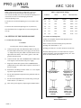
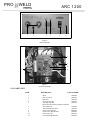
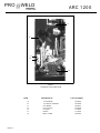
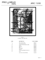
OPERATION/ MAINTENANCE
MANUAL
PRO
WEL D
ARC 1 2 0 0
TABLE OF CONTENTS
Section
1
SAFETY PRECAUTIONS
1.0
2.0
3.0
4.0
4.1
4.2
5.0
6.0
7.0
8.0
8.1
8.2
9.0
9.1
9.2
10.0
10.1
10.2
11.0
12.0
PAGE
INTRODUCTION.......................................................
1
WARRANTY...............................................................
1
UNPACKING YOUR UNIT.......................................
1
SUGGESTED SAFETY PRECAUTIONS................
1
PERSONAL SAFETY PRECAUTIONS…………….
1
POWER SUPPLY SAFETY PRECAUTIONS……… 2
GENERAL DESCRIPTION.......................................
2
ELECTRICAL INPUT REQUIREMENT.................
2
CONTROL PANEL DESCRIPTION......................
3
WELD GUN SETUP...................................................
3
PLUNGE LENGTH.....................................................
3
CHECKING GUN LIFT.............................................
4
SETTING UP THE POWER SOURCE....................
5
CONNECTIONS AND SETTINGS………………….
5
WELD TEST AND INSPECTION…………………..
5
MAINTENANCE.............................................................. 6
WELD CABLES……………..………………………….. 6
INTERNAL CLEANING……………………………… 6
TROUBLE SHOOTING……………………………….. 7
PARTS LIST…………………………………….
8,9,10
LIST OF FIGURES
1
2
3
4
5
6
7
8
9
10
11
JUMPER LINK ARRANGEMENT...........................
CONTROL PANEL FRONT.....................................
STANDARD GUN SET-UP........................................
WELD INSPECTION.................................................
FUSE BLOCK..............................................................
CONTROL PANEL…………………………..............
PCB ENCLOSURE…………....................................
CONTROL UNIT-SIDE VIEW...................................
CONTROL UNIT SIDE VIEW….................................
GUN TIME CONTROL PCB………………………….
CURRENT CONTROL PCB.......................................
2
3
4
5
6
8
8
9
10
11
12
PRO
WEL D
ARC 1 2 0 0
PRO
WEL D
ARC 1 2 0 0
PRO
WEL D
ARC 1 2 0 0
PRO
WEL D
ARC 1 2 0 0
PRO
WEL D
1.0 INTRODUCTION
Your new stud welding equipment has been carefully constructed using the finest components and material available.
Used properly, this equipment will give you many years of
profitable, efficient service.
The system incorporates the latest in engineering advances for
complete, reliable end welding of mild steel, stainless steel
and aluminum fasteners.
A careful study of this manual will enable you to understand
how the welder operates to insure proper performance under
all conditions.
2.0 WARRANTY
The electrical and mechanical components of the stud
welder are thoroughly performance inspected prior to assembly in the welder. The assembled welder is completely performance checked. The welder is delivered to you in functional electro-mechanical condition.
All parts used in the assembly of the welder and its accessories are fully warranted for a period of 1 YEAR from the
date of delivery. In addition, the welding capacitors are warranted for a period of 1 YEAR from the date of delivery. The
printed circuit boards used in all proweld equipment are warranted for a period of 3 years.
Under the warranty, the manufacturer reserves the right
to repair or replace, at their option, defective parts which fail
during the guarantee period. Notice of any claim for warranty
repair or replacement must be furnished to the manufacturer
by the purchaser within ten (10) days after the defect is first
discovered. The manufacturer does not assume any liability
for paying shipping cost or any labor or materials furnished
where such cost are not expressly authorized in writing.
The manufacturer does not warrant any parts or accessories against failures resulting from misuse, abuse, improper
installation, maladjustment, or use not in accordance with the
operating instructions furnished by the manufacturer. The
warranty is valid only when studs are purchased from sources
approved by the manufacturer or are of identical specifications to the manufacturer’s
3.0 UNPACKING YOUR UNIT
Upon receipt of your unit, place it as close as possible to the
point of installation before unpacking it. Once the unit is unpacked, it is recommended that you inspect it for any physical
damage that may have occurred in shipping.
PAGE 1
ARC 1 2 0 0
Your unit has been completely assembled and inspected at
the factory. Upon receipt, the unit must be hooked up to the
recommended incoming power before welding.
Place the unit in a large enough area to provide adequate ventilation. Do not restrict the air flow around the front louvers
or from the fan at the rear of the unit. Do not allow water to
enter the unit in any way.
4.0 SUGGESTED SAFETY PRECAUTIONS
In any welding operation, it is the responsibility of the welder
to observe all safety rules to insure his or her personal safety
and to protect those working in the area.
Reference is directed without endorsement or recommendation to ANSI Z49.1, Safety in Welding and Cutting, and to
AWG Publication A6,1-66, Recommended Safe Practices for
Gas-Shielded Arc Welding.
4.1 Personal Safety Precautions
1. Always treat electricity with respect. Under open circuit
conditions, the welding machines output voltage may be dangerous.
2. Don’t work on live circuits or conductors. Disconnect the
main power before checking the machine or performing any
maintenance or repair operations.
3. Be sure the welding machine cabinet is properly grounded
to a good electrical ground. Consult local electrical codes.
4. Never operate a welder in the rain, or operate a welder
while standing in water. Avoid wearing wet or sweaty clothes
when welding.
5. Don’t operate with worn or poorly connected cables, and
don’t operate the weld gun with loose cable connections. Inspect all cables frequently for insulation failures, exposed
wires, loose connections and repair as needed.
6. Don’t overload welding cables or continue to operate with
over heated cables.
7. Don’t weld near flammable materials or liquids in or near
the area, or on ducts or pipes carrying explosive gases.
8. Don’t weld on containers which have held combustible or
flammable materials, or on materials which give off flammable or toxic vapors when heated.
PRO
WEL D
9. Be sure to provide proper ventilation when welding in a
confined area.
10. Never look at the electric arc without wearing protective
eye shields.
ARC 1 2 0 0
PRIMARY WIRE
SIZE-AWG
230V
#4
460V
#10
575V
#10
GND
#8
#10
#10
DELAY TYPE FUSE
SIZE IN AMPS
120
60
50
11. Always use the proper protective clothing, gloves, etc.
12. Never strike an arc when near a bystander who is unaware of the dangers of ultraviolet light to their eyes.
L1
L2
L3
4.2 Power Supply Safety Precautions
1. Always connect the frame to the power supply to ground
in accordance with the National Electrical Code and the
manufacturer’s recommendations.
230 VOLT
L1
L2
L3
460 VOLT
2. Installation, servicing, or trouble shooting should be done
by qualified personnel trained to work on this type of equipment.
L1
L2
L3
3. Before servicing this piece of equipment, turn off the disconnect switch at the fuse box.
4. When in operation, all the covers must be on the equipment.
5.0 GENERAL DESCRIPTION
THE PROCESS
Stud welding is a time saving tool which semi-automatically
arc welds the FULL CROSS-SECTION of a weld stud to the
base material in a fraction of a second and develops superior
strength over normal arc welding procedures.
Since the ARC-1200 stud welding system provides the
proper arc length and allows you to select the proper arc time
and welding current, the variables that affect weld quality are
minimized.
THE UNIT
The ARC-1200 is a compact and portable stud welding
power supply capable of welding studs thru 5/8” diameter
weld base. The fully regulated power supply which operates
on three phase power produces a smooth, stable welding arc.
Both the weld time and weld current are infinitely adjustable
for preciseness and repeatability.
575 VOLT
Figure 1
Jumper Link Arrangement
6.0 ELECTRICAL INPUT REQUIREMENT
This welding power source is designed to be operated from
three-phase, 60 Hertz, AC power supply which has a line
voltage rating that corresponds with one of the electrical input voltage shown on the nameplate or input data label. Consult the local electric utility if there is any question about the
type of electrical system available at the installation site or
how proper connections to the welding power source are to
be made.
The power unit should be operated from a seperately fused or
circuit breaker protected circuit.
The primary input voltage connection terminal board is located behind the access door on the rear panel.
Install three primary leads plus one ground wire (see FIG. 1
for proper wire and fuse sizes) through the inlet hole in the
rear of the unit.
The primary cables connect to terminals labeled L or LINE.
A FOURTH LEAD (GROUND CONNECTION) SHOULD
BE FASTENED TO THE TERMINAL LABELED GND.
The other end of the ground lead or cable should be attached
to a suitable ground such as a water pipe, ground rod, ect.
Use whatever grounding means is acceptable to the local
PAGE 2
PRO
WEL D
ARC 1 2 0 0
Figure 2
CONTROL PANEL FRONT
CAUTION
The stud labeled GND is connected to the unit chassis and is
for grounding purposes only. Do not connect a wire from the
terminal labeled GND to one of the three-phase line terminals as this may result in “hot” power unit chassis
This unit is equipped with input voltage jumper links either
installed or in a bag on the jumper link board to allow operation from different line voltages. If installed, the jumper links
are positioned for the highest voltage stated on the nameplate
or on the input data label. In either case the jumper links
should always be checked to see if they are properly positioned for the voltage being used.
Open the access door located on the lower portion of the rear
panel to expose the jumper link board. If necessary, reposition the jumper links to match the line voltage being used.
(see Figure 6.1)
7.0 CONTROL PANEL DESCRIPTION
START/STOP PUSH BUTTON
Momentarily depressing the START button will energize the
main contactor inside the unit allowing all circuits to be activated and the the cooling fan to run. Momentarily depressing
the STOP button will deactivate the entire machine.
TIME RANGE SWITCH
This switch is used to select either the “A” or “B” time range
settings on the time adjustment knob.
PAGE 3
THERMAL/GUN FAULT LED INDICATOR
The thermal/gun fault LED “on” indicates either the internal
temperature in the main transformer has reached its maximum or there is a shorted gun solenoid or a shorted control
cable. In either case the LED will stay “on” and lockout the
gun from triggering.
If there is a gun fault, by unplugging the gun control cable at
the welder the LED will be “off” when the welder is first
turned off then turned back on. If there is a thermal overload
the LED will remain “on” until the temperature on the transformer comes down to a safe operating temperature.
8.0 WELD GUN SET-UP
8.1 Plunge Length
1. A different and correctly sized chuck and ferrule grip are
needed for each different stud diameter and style that will be
welded (see PRO WELD Accessories catalog for help in this
area). The appropriate chuck, or stud holder, is inserted into
the tapered chuck adapter and tapped lightly to insure a tight
fit. The ferrule grip is inserted in the hole in the foot and secured with the locking screws to hold it in place.
2. Studs must NOT bind or hang up on the foot, ferrule grip,
or ferrule during the entire stud welding process. To assure
this, the foot/ferrule arrangement must be centered in relation
to the stud to be welded. To assure centering, loosen the leg
screws that hold the foot to the legs. Place a stud in the
chuck and a ferrule in the ferrule grip. With the leg screws
loosened, the foot will move freely in all directions. Adjust
the foot so that the stud is centered in the ferrule and no contact occurs between the stud and the ferrule during retraction
or forward plunge of the stud.
PRO
WEL D
3. The “plunge length” is the amount of the stud exposed beyond the ferrule during initial set-up. Set the plunge by loosening the leg adjusting screws and moving the foot until the
stud extends 1/8” to 3/16” past the end of the ferrule. Tighten
the leg adjusting screws after setting the plunge and recheck
centering to be sure the stud is aligned properly in the ferrule.
4. The lift height, which determines the arc length, has been
preset at the factory and will automatically lift and plunge the
stud during the welding process. “Lift”, is the distance the
gun will raise the stud above the welding surface during the
weld. This distance governs the voltage and the arc. Improper lift will cause unsatisfactory welds. Refer to paragraph 8-1 if it becomes necessary to adjust the lift height.
5. Make sure that the cables are connected to the power
source (standard set-up is straight polarity - Negative to controller (or gun) and Positive (ground cable) to the work surface).
6. Turn on the power supply and adjust the current and time
for the weld base diameter of the fastener to be welded.
7. Place the gun, loaded with the stud and ferrule, squarely
against the grounded work surface. The main spring in the
gun will take up the “plunge length” and the ferrule will seat
against the base plate.
DO NOT MOVE THE GUN DURING THE WELD CYCLE
8. Pull the trigger holding the gun completely still as above.
The gun will lift the stud from the base plate and draw an
arc. The end of the stud and the adjacent material of the base
plate, will be melted by the weld arc.
The gun will then plunge the stud into the molten pool, extinguishing the arc, to end the controlled portion of the weld
ARC 1 2 0 0
9. After the controlled weld cycle, allow the molten metal to
solidify briefly with the work surface to assure completion
of the cycle (about an extra second holding "still" after the
weld is usually sufficient).
10. Remove the gun from the work by lifting straight away
from the welded stud (this will assure better life to the gun's
expendable accessories). The ferrule may now be removed
by breaking it away from the welded stud to allow inspecttion of the weld results. After inspection of sample welds the
gun can be adjusted, as per the step in this procedure,
for optimum results.
8.2 Checking Gun Lift
To measure lift, turn the stud welding unit on and set the
timer to maximum time. (On certain units there may be a Lift
Check switch available, and in these cases this switch can be
used to check lift.) Trigger the gun in the air, or on a
non-grounded or insulated surface, to observe the lift cycle.
Measuring the distance the stud or gun mechanism
moves equals lift - usually this can be easily done by visual
observation or simple measurement against a static reference point (i.e. the ferrule properly seated in the ferrule
grip).
Recommended Lift Settings
Stud Base Dia.
Less than 1/2”
1/2” through 3/4”
Greater than 3/4”
Lift Setting
1/16”
3/32”
7/64”
PAGE 4
PRO
WEL D
When it does become necessary to adjust lift, you do so by
removing the rear cap from the gun. This will expose the
rear coil yoke assembly, the set screw and the lift adjusting screw
(Loosen the set screw to avoid damaging the threads
of the lift adjusting screw).
To increase lift: turn the lift adjusting screw out (counter clockwise).
To decrease lift: turn the lift adjusting screw in (clockwise).
Once the lift has been set, tighten the set screw and replace the
rear cap.
ARC 1 2 0 0
Table 9-1 Approximate Settings
Stud Base
Weld
Weld
Minimum Plate
Inches
mm
Seconds
Ampers
Inches
mm
1/4
6.4
0.20
425
0.048
1.22
5/16
7.9
0.25
500
0.060
1.52
3/8
9.5
0.33
550
0.075
1.91
7/16
11.1
0.40
675
0.089
2.26
1/2
12.7
0.55
800
0.120
3.05
5/8
15.9
0.67
1200
0.148
3.76
9.0 SETTING UP THE POWER SOURCE
9.2 Weld Test and Inspection
9.1 Connections and settings.
Testing of weld quality beyond visual inspection varies
with stud characteristics.
CAUTION
Turn the power off before making connections
a)
Connect the male end of the GROUND CABLE to the positive GROUND terminal of the power supply, and secure the
“C” clamp to the base plate. Make sure both connections are
tight and the base metal is free of heavy paint or rust at the
ground connection points.
Refer to AWS (American Welding Society) Structure
Welding code AWS D.1Rev. 1-76.
Welding procedures are covered in Sections 4.28 and 4.29.
Weld test and inspection is covered in Section 4.30, paragraphs 1 through 4. (American Welding Society, inc., 2501
N.W. 7th. Street, Miami, Fla. 33125)
b) Connect the male end of the COMBINATION CABLE SET
to the negative GUN terminal of the power supply.
c)
Plug in the control cable portion of the COMBINATION
CABLE SET into the control cable receptacle in the front of
the power supply.
d) Position the Time Range switch in either “A” or “B” depending on the required weld time.
e)
Set the Time adjustment required for the particular stud size.
(see table 9-1)
f)
Set the Current adjustment to the current setting for the particular stud size. (see table 9-1)
GOOD STUD WELD
A good full fillet
STUD HANG UP
Adjust foot to
insure the stud is
centered in the
ferrule
COLD WELD
Increase weld
current and/or
weld time
HOT WELD
Reduce weld
current and/or
weld time
g) Turn on the power supply by depressing the START button.
figure 4
WELD INSPECTION
PAGE 5
PRO
WEL D
ARC 1 2 0 0
A. Bend Test
CAUTION
Repeatedly bend the stud away from its axis until failure occurs.
B. Torque Test - Threaded Studs
Read and follow the safety information at the begining of
this section before proceding.
Twist the stud to point of failure. Apply a twisting tensile load by
using a collar, washer and nut.
10.1 WELD CABLES
C. Test Results
Every three months inspect cables for breaks in insulation.
Repair or replace cables if insulation breaks are present.
Clean and tighten connections at each inspection.
In an acceptable weld, failure will occur in the stud material or
tear out of a thin base plate. Failure in the weld requires adjustment of pocedure, weld time, weld current, or gun setup.
10.0 MAINTENANCE
10.2 INTERNAL CLEANING
Every six months blow or vacuum dust and dirt from th einside fo the welding power source. Remove the outer enclosure, and use a clean, dry airstream or vacuum suction for
the cleaning operation. If dusty or dirty conditions are present, clean the unit monthly.
CAUTION
Electric Shock Can Kill:
•
•
Do not touch live electrical parts.
Shut down welding power source, and disconnect input
power before inspecting, maintaining, or servicing.
1 AMP
F9
Lockout/tagging procedures consist of padlocking line disconnect switch in the open position, removing fuses from fuse box,
or shutting off and red-tagging circuit breaker or other disconnecting device.
1 AMP
F8
1 AMP
F7
1 AMP
F6
HOT SURFACES can cause severe burns.
1 AMP
F5
•
5 AMP
4
F4
25 AMP
SLO BLO
F3
25 AMP
SLO BLO
F2
25 AMP
SLO BLO
F1
MOVING PARTS can cause serious injury.
•
Keep away from moving parts.
Allow cooling period before servicing.
Figure 5
FUSE BLOCK
PAGE 6
PRO
WEL D
ARC 1 2 0 0
11.0 TROUBLE SHOOTING
Whenever possible, have a qualified electrician do the maintenance and trouble shooting work. Turn the input power off using the disconnect switch at the fuse box before working inside the machine.
Trouble
Possible Cause
Unit trips off without
welding.
1. Defective main SCR.
2.
3.
4.
5.
Defective sustaining arc SCR.
Defective 600-0012 P.C.board
Defective 600-0010 P.C. board.
Shorted control cables.
What To Do
1. Check for defective SCR and
replace.
2. check and replace.
3. Replace.
4. Replace.
5. Repair.
Low output.
1. Input fuse blown. Unit is single
phase.
2. Incorrect jumper link connection
on primary board.
3. Defective 600-0012 P.C. board.
4. Defective 600-0010 P.C. board.
5. Defective current potentiometer.
1. Replace fuse, repair input line.
Check for reason for fault.2.
2. Check jumper links on primary
board for proper voltage.
3. Replace.
4. Replace.
5. Replace.
Maximum output but
no control.
1. Defective 600-0012 P.C. board.
2. Open lead going to shunt
(shielded cable).
3. Defective current potentiometer.
1. Replace.
2. Repair broken leads on
connection.
3. Replace.
Gun does not lift.
1. Blown 5 amp fuse.
2. Defective 600-0010 P.C. board.
3. Defective control cable or
gun coil.
4. Defective 600-0012 P.C. board.
5. Defective 600-0011 P.C. board.
6. Blown 1 amp fuse
1. Check and replace fuse.
2. Replace.
3. Repair short in cable, replace
gun coil.
4. Replace.
5. Replace.
6. Check and replace fuse
Gun lifts but does not
weld.
1.
2.
3.
4.
5.
6.
1.
2.
3.
4.
5.
6.
Gun lifts but does not
Plunge.
1. Defective 600-0010 P.C. board.
2. Defective time potentiometer.
PAGE 7
Blown 25 amp sustaining arc fuse.
Defective sustaining arc SCR(s).
Defective 600-0010 P.C. board.
Defective 600-0012 P.C. board
Defective choke coil.
Open weld cable or bad weld
ground connection.
Check and replace fuse.
Replace bad part(s).
Replace.
Replace.
Check and Replace.
Check and Repair.
1. Replace.
2. Replace.
PRO
WEL D
1
ARC 1 2 0 0
2
3
4
5
6
Figure 6
FRONT PANEL
8
9
10
7
11
Figure 7
PCB ENCLOSURE
12.0 PARTS LIST
ITEM
1
2
3
4
5
6
7
8
9
10
11
DESCRIPTION
PART NUMBER
Knob
Hi/Low Switch
Red LED
Green, Neon Light
Start/Stop Operator
(Open/Closed Contacts Needed for Operator)
Arc 1200 Decal
SCR, Isolated, 25A 400V
PCB, Current Control
Choke Coil, (TR1600/450)
PCB, Time CTR.
Circuit Board Hold Down
102-0060
104-0014
108-0028
102-0087
104-0016
122-0020
108-0042
600-0012
105-0004
600-0010
102-0098
PAGE 8
PRO
WEL D
ARC 1 2 0 0
15
12
13
14
16
Figure 8
CONTROL UNIT-SIDE VIEW
ITEM
12
12
13
14
15
15
16
PAGE 9
DESCRIPTION
14” Fan Blade
1/2” Hub for Fan Blade
Fuse Holder
Fuse 6A 250V
Contactor
Interloc
Motor 1/8 HP
PART NUMBER
102-0083
102-0084
104-0033
120-0008
113-0019
113-0020
102-0085
PRO
WEL D
ARC 1 2 0 0
21,22
17
23
18
19
24
25
20
Figure 9
CONTROL UNIT-SIDE VIEW
ITEM
17
17
18
19
20
21
22
23
24
25
DESCRIPTION
PART NUMBER
Norm. Open Contact
Norm. Closed Contact
M/Trans/1200/230/440/575/60HZ
Wheels
Axel Cap
SCR
SCR Clamp
Buss Bar
C/Trans/3000/60HZ/230/460/575V
Shunt
104-0017
1040018
105-0019
102-0036
102-0027
108-0057
102-0106
124-0045
105-0015
102-0081
Front Caster (NOT SHOWN)
102-0082
PAGE 10
PAGE 11
OP
107
C113
D101
R133
Figure 10
GUN TIME CONTROL P.C. BOARD
P/N 600-0010
R154
R147
C115
D113
V110
D115
R117
ZD101
D104
D112
R116
V109
C105 +
D109
D110
R111
OP110
C104
+
R146
IC101
D127
R113
C101
+
R125
R112
R118
D114
IC102
ZD102
R119
D117
C102
V104
V102
VR101
R105
V111
V108
R115
R141
R140
R142
D103
R114
D116
R145
R144
D126
R131
R132
D119
IC104
WEL D
ZD104
R102
R108
R126
ZD103
D140
OP101
R127
D105
R103
D102
C108 +
R110
R109
R104
V112
R153
D106
OP
102
R155
D125
R128
D118
R130
C106
R124
R123
D122
R121
IC103
R122
V106
D107
D108
R137
Q101
V105
ON
D111
+
+
D124
D138
OFF
R101
OP104
D139
R139
R138
C110
C109
ZD105
D134
C112
R134
R143
C103
R136
R135
R150
R149
R120
+
C107
D135
D133
D132
OP
106
R151
C114
D136
D137
R152
OP
105
C111
OP
109
1 2
OP
108
D131
D130
D129
R129
PRO
ARC 1 2 0 0
D120
V103
V107
OP
103
R148
+
R107
D121
R327
R333
R350
+
R328
ZD305
D324
D325
TR301
R341
C301
R302
D322
IC306
R301
D302
C302
R309
ZD301
D305
R345
R343
R312
ZD302
ZD303
R313
D310
D315
R324
R329
R307
R306
IC301
R311
R310
IC302
D317
R315
R314
IC303
R318
R308
R321
R317
IC304
C307
D319
R323
R322
WEL D
D301
D303
D304
D308
D306
D307
C303
R319
R316
R332
D309
R303
D312
C304
ZD304
R320
R326
R348
C310
R305
C309
R334
R344
R347
D311
D314
D320
R342
OP301
R340
R339
R336
IC307
R331
OP302
C308
R349
OP303
V303
R337
R346
R325
+
R338
R330
C306
R335
V301
IC305
PRO
ARC 1 2 0 0
D316
V304
D318
R304
Q301
C305
D328
V302
V305
D321
D313
C311
+
+
D323
D326
D327
Figure 11
CURRENT CONTROL P.C. BOARD
P/N 600-0012
PAGE 12
MANUFACTURED BY
PRO
WELD
MADE IN THE U.S.A.