1
Horner Electric's
Release 3.4 GeniusTM
Operator Interfaces
User's Manual Supplement, for
HE693OIU187, HE693OIU197,
HE693OIU297, and HE693OIU907
Revision B or later
SUP0192-02
Page ii
PREFACE
PREFACE
Page iii
PREFACE
This manual explains how to use the Horner APG Genius Operator Interface Units for use with
the CEGELEC Alspa 8000 family of Programmable Logic Controllers.
Copyright (C) 2001 Horner APG, LLC., 640 North Sherman Drive, Indianapolis Indiana
46201-3899. All rights reserved. No part of this publication may be reproduced, transmitted,
transcribed, stored in a retrieval system, or translated into any language or computer language,
in any form by any means, electronic, mechanical, magnetic, optical, chemical, manual or
otherwise, without the prior agreement and written permission of Horner Electric, Inc.
Information in this document is subject to change without notice and does not represent a
commitment on the part of Horner APG, LLC.
Alspa 8000 and P8 are Trademarks of CEGELEC
Page iv
PREFACE
LIMITED WARRANTY AND LIMITATION OF LIABILITY
Horner APG, LLC. ("HE") warrants to the original purchaser that the Operator Interface Unit
manufactured by HE is free from defects in material and workmanship under normal use and
service. The obligation of HE under this warranty shall be limited to the repair or exchange of
any part or parts which may prove defective under normal use and service within two (2) years
from the date of manufacture or eighteen (18) months from the date of installation by the original
purchaser whichever occurs first, such defect to be disclosed to the satisfaction of HE after
examination by HE of the allegedly defective part or parts. THIS WARRANTY IS EXPRESSLY
IN LIEU OF ALL OTHER WARRANTIES EXPRESSED OR IMPLIED INCLUDING THE
WARRANTIES OF MERCHANTABILITY AND FITNESS FOR USE AND OF ALL OTHER
OBLIGATIONS OR LIABILITIES AND HE NEITHER ASSUMES, NOR AUTHORIZES ANY
OTHER PERSON TO ASSUME FOR HE, ANY OTHER LIABILITY IN CONNECTION WITH
THE SALE OF THIS OPERATOR INTERFACE UNIT. THIS WARRANTY SHALL NOT APPLY
TO THIS OPERATOR INTERFACE UNIT OR ANY PART THEREOF WHICH HAS BEEN
SUBJECT TO ACCIDENT, NEGLIGENCE, ALTERATION, ABUSE, OR MISUSE. HE MAKES
NO WARRANTY WHATSOEVER IN RESPECT TO ACCESSORIES OR PARTS NOT SUPPLIED BY HE. THE TERM "ORIGINAL PURCHASER", AS USED IN THIS WARRANTY,
SHALL BE DEEMED TO MEAN THAT PERSON FOR WHOM THE OPERATOR INTERFACE
UNIT IS ORIGINALLY INSTALLED. THIS WARRANTY SHALL APPLY ONLY WITHIN THE
BOUNDARIES OF THE CONTINENTAL UNITED STATES.
In no event, whether as a result of breach of contract, warranty, tort (including negligence) or
otherwise, shall HE or its suppliers be liable of any special, consequential, incidental or penal
damages including, but not limited to, loss of profit or revenues, loss of use of the products or
any associated equipment, damage to associated equipment, cost of capital, cost of substitute
products, facilities, services or replacement power, down time costs, or claims of original
purchaser's customers for such damages.
To obtain warranty service, return the product to your distributor with a description of the
problem, proof of purchase, post paid, insured and in a suitable package.
PREFACE
Page v
ABOUT THE PROGRAM EXAMPLES
Any example programs and program segments in this manual are included solely for illustrative
purposes. Due to the many variables and requirements associated with any particular
installation, Horner Electric cannot assume responsibility or liablity for actual use based on the
examples and diagrams. It is the sole responsibility of the system designer utilizing the Operator
Interface Unit to appropriately design the end system, to appropriately integrate the Operator
Interface Unit and to make safety provisions for the end equipment as is usual and customary
in industrial applications as defined in any codes or standards which apply.
Page vi
PREFACE
TABLE OF CONTENTS
CHAPTER 1: INTRODUCTION
1.1
1.2
1.3
1.4
1.5
1.6
1.7
About this Manual Supplement .
.
The Genius Network
.
.
.
The Advantages of Genius Operator Interface
The OIU as a Genius Device
.
.
Genius Data .
.
.
.
.
Model Features
.
.
.
.
Model Specifications
.
.
.
.
.
.
.
.
.
.
.
.
.
.
.
.
.
Page 1-1
Page 1-1
Page 1-1
Page 1-1
Page 1-2
Page 1-3
Page 1-4
Using the Genius OIU to Display PLC Data
.
.
Page 2-1
2.1.1 Block Number
2.1.2 Reference Type
.
.
.
.
.
.
.
.
.
.
Page 2-1
Page 2-1
Function Keys
.
.
.
.
.
Page 2-2
2.2.1 Function Keys as Momentary Pushbuttons
.
Page 2-2
Using a Genius OIU with the Series 90-30 PLC .
Using a Genius OIU with the Series 90-70 PLC .
.
.
Page 2-2
Page 2-4
CHAPTER 2: APPLICATION DEVELOPMENT
2.1
2.2
2.3
2.4
.
CHAPTER 3: THE KEYPAD SETUP MENU
3.1
3.2
3.3
Genius Menu Selections
Genius Setup
.
Cfg Dgram Frq
.
.
.
.
.
.
.
.
.
.
.
.
.
.
.
.
Page 3-1
Page 3-1
Page 3-2
.
.
.
.
.
.
.
.
Page 4-1
Page 4-1
CHAPTER 4: SOFTWARE CONFIGURATION
4.1
4.2
Miscellaneous Register Menu
The Autorun Menu .
.
APPENDIX A: INSTALLATION INFORMATION
A.1
A.2
A.3
A.4
Mounting
Providing Power
Communications
Placing the OIU Into Service
CHAPTER 1: INTRODUCTION
Page 1-1
CHAPTER 1: INTRODUCTION
1.1
About this Manual Supplement
This document is a supplement to Horner APG document (Horner APG’s Release 3.4 Operator
Interface Units User’s Manual). It is intended to provide the necessary additional information to effectively integrate
Horner APG’s Genius Operator Interface Units. Users of this document should utilize the document to
familiarize themselves with Horner Electric OIUs and their operational characteristics. Horner Genius OIUs operate
nearly identically to the units described in this doccument.
1.2
The Genius Network
Horner APG offers a variety of Operator Interface products. The Horner Electric product line includes models
communicating serially (using SNP protocol) and over a high speed industrial LAN (Genius). The Genius LAN is a
proven, industrial rugged high speed LAN. Relative to typical RS-232 or RS-485 serial communications, it offers far
better performance and flexibility. Genius is a token passing network with baud rates up to 153.6kbaud, consisting
of up to 32 devices. Devices available for the Genius LAN include PLC interfaces, a wide variety of I/O Blocks, personal
computer interfaces, variable frequency drive interfaces, and a host of third party devices.
1.3
The Advantages of Genius Operator Interface
No Dedicated Cabling or PLC Interface. Operator Interfaces may be located remotely, using the same cabling and
PLC interface modules as the distributed I/O. For instance, instead of a PLC Coprocessor or Communications card
and dedicated RS-485 cabling, the Genius OIU can reside on the same cable as the existing Genius I/O Blocks,
acquiring data from the existing Genius bus controller.
Multiple, Distributed OIUs without Significant Performance Sacrifice. Many OIU manufacturers have schemes where
a “Master” OIU communicates with the PLC serially and then passes data on to “Slave” OIUs connected to the master.
These schemes, while possessing some merit, offer significant performance decreases as additinal OIUs are added
to the master. Several Genius OIUs residing on a single Genius bus each typically offer higher data updates than
a single master serial OIU, let alone a single OIU distributing data to several slave OIUs.
Data Access from I/O Blocks without PLC Intervention. Horner APG Genius OIUs can be used on Genius networks
without PLCs. For example, Horner OIUs can be connected via Genius directly to one or more PowerTRAC
blocks to display the power data being gathered by the blocks. A PLC bus controller is not required, as the OIU has
the ability to communicate with the PowerTRAC block directly without the need to go through a PLC interface.
1.4
The OIU as a Genius Device
Like any other Genius device, Horner Genius OIUs reside on the LAN and must be configured with a Serial
Bus Address, 0 to 31. On the OIU, this Genius bus address is set via an 8 position dip switch, which is also used
to set the baud rate. The Genius hardware interface is a GENI printed circuit board, which is one of the two printed
circuit boards which make up the OIU. As a GENI-based device, Horner Electric OIUs are intelligent and can read
and write all forms of data on the network.
Page 1-2
1.5
CHAPTER 1: INTRODUCTION
Genius Data
There are two means of data transfer on the Genius network, global data and datagrams.
Global data. Global data is data broadcast by Genius devices blindly onto the network. The data is not directed
to any particular Genius device, but is available to all devices on the network with the ability to read and process the
data. The Horner Electric Genius OIUs can read up to 64 words of global data from each device, and broadcast up
to 64 words of its own global data output. A common useage of global data output by the OIU would be to broadcast
the state of its function keys as global data. Any device (such as a Genius bus controller) with the ability to read
and interpret global data then has the ability to detect the pressing of one or more function keys.
Datagrams. Datagrams are a directed message from one Genius device to another. Datagrams are commonly used
by the Genius OIUs to display PLC data. Whenever the OIU needs to know the status of a PLC register not broadcast
as global data, the OIU will send a datagram to the Genius bus controller requesting this information. The bus
controller then processes the message and sends a datagram response to the OIU which includes the requested
data.
CHAPTER 1: INTRODUCTION
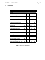
1.6
Page 1-3
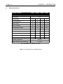
Model Features
Operator Interfaces
OIU187
OIU197
OIU297
OIU907
Genius Connection
þ
þ
þ
þ
RS-232 Port for Programming
þ
þ
þ
þ
20 key Numeric Keypad
þ
þ
Programmable Function Keys
12
12
Features
þ
14
12
þ
I/O Mapped LED's
2 x 16 Liquid Crystal Display
þ
þ
2 x 20 Vacuum Fluorescent Display
þ
4 x 20 Vacuum Fluorescent Display
Character Height
þ
.375"
.197"
.197"
.44"
Real-time Calendar Clock
þ
þ
þ
þ
Configurable with IBM Software
þ
þ
þ
þ
Configurable from Keypad
þ
þ
Alarm Enunciation Capability
þ
þ
þ
þ
Serial Printer Support
þ
þ
þ
þ
Double Integer Read/Write
þ
þ
þ
þ
Performs Linear Scaling (mx + b)
þ
þ
þ
þ
Genius Redundancy
þ
þ
þ
þ
Eight User Definable Characters
þ
Message Chaining
þ
þ
þ
þ
Keypad Masking to Disable Indiv. Keys
þ
þ
þ
þ
Table 1-1. Feature List by Model Number.
þ
Page 1-4
1.7
CHAPTER 1: INTRODUCTION
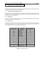
Model Specifications
Operator Interfaces
OIU187
OIU197
OIU297
OIU907
Specifications
NEMA Rating
4-12
Height (inches)
5.50"
5.50"
5.50"
7.25"
140
140
140
185
7.75"
7.75"
7.75"
11.75"
197
197
197
299
2.13"
2.13"
2.63"
3.50"
Mounting Depth (millimeters)
54
54
67
89
24VDC Power Requirements (mA)
250
250
500
500*
DC Power On Current Surge (A/ms)
1/30
1.5/50
2.1/100
3/100
85-267VAC Power Requirements (mA)
NA
NA
NA
500
-
-
-
8/25
Height (millimeters)
Width (inches)
Width (millimeters)
Mounting Depth (inches)
AC Power On Current Surge (A/ms)
Operating Temperature
0 to 60°C
Relative Humidity (non-condensing)
5 to 95%
NA = not available, * = optional (-24 suffix)
Table 1-2. Specifications List by Model Number.
CHAPTER 2: APPLICATION DEVELOPMENT
Page 2-1
CHAPTER 2: APPLICATION DEVELOPMENT
This chapter lists the additional features available with Horner Electric Genius OIUs. For descriptions of all the
available features, once again reference document HFK-XX7.
2.1
Using the Genius OIU to Display PLC Data
The Horner Electric Genius OIUs display data in the same fashion as the SNP OIUs, but differ slightly in the use
of the Block Number parameter and also offer additional Reference Types. The Data Field Type, Range, and Base
are identical to those used with SNP OIUs.
2.1.1
Block Number
The Genius OIUs utilize the "Block Number" parameter to specify the Genius Bus Address of the device containing
the data to be displayed on the OIU, from 0 to 31.
2.1.2
Reference Type
The Genius OIUs offer more reference types than the SNP OIUs, due to the fact that they can access data from
Genius Blocks as well as PLCs. Therefore they feature all PLC Reference Types, plus some Genius Reference
Types. Supported Reference Types are listed in the Table(s) below:
Reference Type
Description
Default # of Bits
%R
Register Memory
16
%AI
Analog Input
16
%AQ
Analog Output
16
%I
Discrete Input
1
%Q
Discrete Output
1
%T
Temporary Coils
1
%M
Internal Coils
1
%S
System Memory
1
%SA
System Memory
1
%SB
System Memory
1
%SC
System Memory
1
%G
Genius Global Data
1
Table 2-1. PLC Reference Types
Page 2-2
CHAPTER 2: APPLICATION DEVELOPMENT
Reference Type
Description
Default # of Bits
BIO
Discrete Genius I/O
1
BAI
Analog Block Input
16
BAQ
Analog Block Output
16
PWR
PowerTRAC Block Data
16
CFG
Block Configuration Data
8
FLT
Block Diagnostic Data
8
GLB
Genius Global Data
16
Table 2-2. Genius Reference Types
2.2
Function Keys
Function keys are also utilized identically as with SNP OIUs. However, when used as momentary pushbuttons, they
are typically applied in a slightly different fashion.
2.2.1
Function Keys as Momentary Pushbuttons
To map the function keys into PLC I/O as a pushbutton, the function key register must be set. The function key
register is a register in the PLC which is constantly updated by the OIU with the status of the function keys and/
or other keys on the OIU keypad.
If the function key register is assigned to a PLC Reference Type (%M, %T, %R etc.), the Block Number for the
function key register must reference a PLC bus controller. Every time a function key is pressed, the OIU will send
a datagram to the bus controller, and that datagram will cause the appropriate register or bit value to change.
An alternate way to map function keys is to map them as OIU Global Data Output. In this case, the Block Number
must reference the OIU Genius Bus Address, and the GLB Reference type must be used. The status of all the OIU
keys will be mapped into Global data, and the current state of all the keys will be broadcast continuously as Global
Data by the OIU. All the keys will be broadcast due to the fact that GLB is a word-type reference.
If the function keys are mapped to global data, the "Global Data Output Size" must be set to a non-zero value.
Otherwise, the OIU will not broadcast any global data, and the function key status will not be broadcast. For
information regarding which keys are mapped to which bits, see the HFK-XX7 document.
2.3
Using a Genius OIU with the Series 90-30 PLC
There are currently three different Genius interface modules for the Alspa 8000 PLCs. These include the Genius
Communications Module (GCM), Enhanced Genius Communications Module (GCM+), and the Genius Bus
Controller (GBC).
Genius Communications Modules (GCM and GCM+). These modules simply support global data. They cannot be
used to control Genius I/O and they also do not support datagram data access. When a Genius OIU is used with
a GCM or GCM+, the OIU can only display the global data broadcast by the module, which is limited to 64 words.
Also, the OIU can write only 64 words of global data which is readable by the module.
CHAPTER 2: APPLICATION DEVELOPMENT
Page 2-3
The Logicmaster Configuration software is used to map incoming global data from the other Genius devices to PLC
registers. Independent blocks of PLC registers are configured for each of the other devices residing on the network.
Also, the PLC registers containing the global data to be output by the PLC are also mapped.
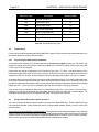
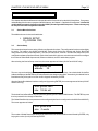
For instance, let’s say that a Genius OIU has Genius bus address of 20, and is configured with 46 words of global
data output. Let’s also say that a GCM+ has a Genius bus address 16, and broadcasts %R1-64 as global data output
from the PLC. A sample Logicmaster configuration screen for this scenario is shown below:
As you can see from the above configuration, data broadcast by the OIU is mapped into PLC registers %R101-%R146,
and data broadcast by the PLC is located at %R1-%R64.
Genius Bus Controller (GBC). Unlike GCM and GCM+ modules, Genius Bus Controllers (GBCs) have the ability to
control I/O and communicate using datagrams. Therefore the OIU can access all of the PLC memory table via
datagrams, as well as monitoring up to 64 words of global data output from the PLC. The datagram access provides
full read/write access to the PLC memory, allowing the OIU and PLC ladder logic to read/write the PLC register space.
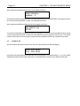
Even with datagram access, global data is still commmonly used in GBC/OIU applications. For instance, data
commonly broadcast by the OIU (function key status, current screen number, and print status) is often mapped as
global data outputs. This is an effective way of managing routinely broadcast data while minimizing datagram traffic.
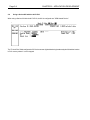
In the sample Logicmaster configuration below, the OIU has a Genius bus address of 29, and broadcasts 4 words
of global data. Words 1 and 2 contain keypad status bits, broadcasting the status of all (up to) 32 OIU keys. Word
3 contains the Current Screen Number, and Word 4 contains the Print Status Register.
Page 2-4
2.4
CHAPTER 2: APPLICATION DEVELOPMENT
Using a Genius OIU with the 90-70 PLC
When using a Genius OIU with the 90-70 PLC, the OIU is configured as a "GENI-based Device".
The "To" and "Size" fields configures the PLC for the amount of global data being broadcast by the OIU and the location
in PLC memory where it is to be mapped.
CHAPTER 3:THE KEYPAD SETUP MENU
CHAPTER 3:
Page 3-1
THE KEYPAD SETUP MENU
This chapter describes the differences in the operation of the Genius OIUs from the built-in Setup Menu. For a greater
understanding of the function or purpose of the OIU features, see Chapter 3, "Application Development". Genius OIU
models without a numeric keypad (such as the OIU297) do not support the setup menu. These units may only
be setup from the OIU configuration software.
3.1
Genius Menu Selections
The additional menu choices are listed below:
> GENIUS SETUP
Cfg DGRAM FRQ
3.2
Genius Setup
This menu selection performs a variety of Genius configuration functions. The configuration functions varies slightly
by model. For instance, the OIU297 and OIU907 receive their Genius Bus Address and Genius Baud Rate
configuration from an 8-poisiton dip switch. The OIU187 and OIU197, however, use either the setup menu or the
configuration software to perform this task. Each of the Genius OIUs, however, uses this menu selection to configure
the number of Global Data Output words, Reference Address, and CPU redundancy register.
After selecting the Genius Setup menu item, the screen appears as follows (OIU187 and OIU197 only):
enter genius bus
address:
29
The user may set the address either by pressing the UP and/or DOWN arrow keys. Once the desired Genius Bus
Address is displayed, the ENTER key must be pressed for the change to take effect. Alternatively, the desired Genius
Bus Address may be keyed in from the numeric keypad, followed by ENTER.
After the Genius Bus Address has been configured (by pressing ENTER), the screen appears as follows (OIU187
and OIU197 only):
enter genius baud
rate: 153.6k std
The desired Genius Baud Rate may be selected by pressing the UP and/or DOWN arrows. The ENTER key must
then be pressed for the change to take effect.
The Global Data Size is the next parameter to be configured (the first to be configured on the OIU297 and OIU907).
The screen appears as follows:
enter global data
size: 0 words
The number of Global Data Output Words is set either with the UP and/or DOWN arrows followed by ENTER, or by
keying in the value (0 to 64) followed by ENTER.
Page 3-2
CHAPTER 3: THE KEYPAD SETUP MENU
After configuring the Global Data size, the screen appears as follows:
enter reference
address: 0
The Reference Address is set either with the UP and/or DOWN arrows followed by ENTER, or by keying in the value
(0 to 32767) followed by ENTER. A value of zero disables the feature.
After configuring the Reference Address, the screen appears as follows:
cpu redund. reg
00%R
To set the CPU Redundancy Register, press the LEFT and RIGHT arrow keys to select the Block Number (usually
31) of the Genius Bus Controller. Press the UP and DOWN arrow keys to select the reference type. The register
number is then keyed in from the numeric keypad, and the pressing the ENTER key completes the process.
3.3
Cfg Dgram Frq
After selecting the Cfg Dgram Frq menu item, the user is prompted with the following display:
Enter max dgram
freq: 4/sec (lo-p)
Pressing the UP and DOWN arrows toggles this selection between the 12 possible settings, 1, 2, 4, 8, 20, or MAX
datagrams/second with either high or low priority. Pressing ENTER is required for the change to take effect.
CHAPTER 4: SOFTWARE CONFIGURATION
Page 4-1
CHAPTER 4: SOFTWARE CONFIGURATION
This chapter describes the different software configuration items present for the Genius OIUs. For complete, stepby-step, detailed instructions, see the HFK-XX7 document
4.1
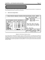
Miscellaneous Register Menu
Figure 4-1. Miscellaneous Registers Screen
Genius OIUs utilize the "Redundancy" Regiser, which is not used by SNP OIUs. Like editing any miscellaneous
register parameter, the cursor keys are used to position the cursor from line to line and column to column. When
the "Register" column is edited, pressing the SPACE bar toggles between the available reference types. The Register
number and "Block" number may be keyed in from the keyboard. The + and - keys are used to increment/decrement
the "Bits" column.
Page 4-2
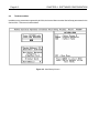
4.2
CHAPTER 4: SOFTWARE CONFIGURATION
The Autorun Menu
In addition to the parameters supported by all OIUs, the Autorun Menu contains Genius Setup parameters for the
Genius OIUs. This screen is shown below.
Figure 4-2. Auto/Startup Screen
APPENDIX A: INSTALLATION INFORMATION
Page A-1
APPENDIX A: INSTALLATION INFORMATION
This appendix lists all the pertinent installation information for each of the OIU model numbers. Panel installation,
power connection, dip switch settings, communications diagrams, etc.
A.1
Mounting
A.2
Providing Power
A.3
Communications Wiring
A.4
Placing the Module Into Service
Page A-2
APPENDIX A: INSTALLATION INFORMATION
Mounting
A1.1
Mounting Requirements
The OIU is designed for permanent panel mounting. To install the OIU:
A.
Cut the host panel as described in the coresponding drawing below:
B.
Remove the rear cover by removing the four (4) [OIU907] or five (5)
[OIU187,197, and 297] screws holding it in place.
C.
Insert the OIU through the panel cutout (from the front). The gasket material should lie
between the host panel and the OIU panel.
D.
Install four (4) [OIU187,197, and 297] or six (6) [OIU907] #6-32
hex nuts on the mounting studs of the OIU. Tighten these nuts until the gasket material
forms a tight seal. Do not overtighten.
E.
Replace the rear cover screws which secure it to the OIU.
F.
Connect the communications and/or printer cables to the OIU serial ports.
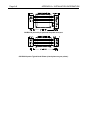
Panel Cutout for HE693OIU187, OIU197, and OIU297
APPENDIX A: INSTALLATION INFORMATION
Panel Cutout for HE693OIU907
Page A-3
Page A-4
APPENDIX A: INSTALLATION INFORMATION
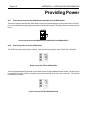
Providing Power
A2.1
Power Requirements for the HE693OIU187, HE693OIU197 and HE693OIU297
These three operator interface units, which feature vacuum fluorescent displays, must be powered from 9-32V DC.
Power is provided to the OIUs through a two position removable terminal strip. The polarity of this connection is shown
below:.
Power Connection for the HE693OIU187, HE693OIU197 and HE693OIU277
A2.2
Power Requirements for the HE693OIU907
The OIU907 unit requires AC power, standard. They accept a wide range AC input, 85-267VAC, 40-440 Hz.
Power Connection for the HE693OIU907
This unit may optionally be DC powered, from 9-32VDC, with a (-24) suffix added to the part number. This power must
be supplied to the three position removable terminal strip mounted on the rear cover of the OIU. The terminal
connection is as follows:
Power Connection for the HE693OIU907-24
APPENDIX A: INSTALLATION INFORMATION
Page A-5
Communications
A3.1
Genius Communications Wiring
All of the OIUs described in this manual communicate with Genius through a 4-pin, removable terminal strip. The
connections provided are identical: Serial 1, Serial 2, Shield Out and Shield In. Shielded, twisted pair wiring should
be used. For exact wiring specifications, refer to document GFK-0412, the Genius Communications Users Manual.
Genius Terminal Connections for HE693OIU187, HE693OIU197,
HE693OIU297 and HE693OIU907
A3.2
Installation Considerations
In addition to construction, proper cable routing is of utmost importance. Communications cabling should be routed
away from high power and I/O wiring, as electrical noise from these conductors can be induced upon the
communications cabling. Once again, for exact wiring specifications, refer to document GFK-0412, the Genius
Communications Users Manual.
A3.3
Genius Communications Settings (OIU187 and OIU197 only)
In order for the Operator Interface Units to commuinicate properly via Genius, they must be configured with the proper
Genius baud rate and assigned a Genius bus address. The OIU 297 and OIU907 utilize dip switches to accomplish
this configuration, but the OIU187 and OIU197 use the configuration software (OIUCFG.exe). To reach the appropriate
sub-menu, invoke the OIUCFG software from DOS and select the proper OIU model (OIU187 or OIU197). From the
Main Menu, select F8 "Select Auto/Setup Mode". This screen contains the Genius configuration parameters, which
include baud rate and Genius bus address, shown below:
OIU187 and OIU197 Software Configuration for Genius Bus Address and Baud Rate
Legal baud rates include 153K Standard, 153K Extended, 76K and 38K. The other Genius parameters shown above
are covered elsewhere in this document.
Page A-6
A3.4
APPENDIX A: INSTALLATION INFORMATION
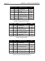
Genius Communications Dip Switches (OIU297 and OIU907 only)
The OIU907 features an 8-position dip switch for configuring the Genius baud rate and device number for the OIU.
This is accessible through an access hole in the rear cover of the OIU, and its settings are listed as follows:
8
7
6
5
4
3
2
1
factory set
7
6
baud rate
5
4
3
2
1
address
5
4
3
2
1
address
CLOSD
CLOSD
153.6K extended
CLOSD
CLOSD
CLOSD
CLOSD
CLOSD
0
OPEN
CLOSD
CLOSD
CLOSD
CLOSD
16
CLOSD
OPEN
38.4K
CLOSD
CLOSD
CLOSD
CLOSD
OPEN
1
OPEN
CLOSD
CLOSD
CLOSD
OPEN
17
OPEN
CLOSD
76.8K
CLOSD
CLOSD
CLOSD
OPEN
CLOSD
2
OPEN
CLOSD
CLOSD
OPEN
CLOSD
18
OPEN
OPEN
153.6K standard
CLOSD
CLOSD
CLOSD
OPEN
OPEN
3
OPEN
CLOSD
CLOSD
OPEN
OPEN
19
CLOSD
CLOSD
OPEN
CLOSD
CLOSD
4
OPEN
CLOSD
OPEN
CLOSD
CLOSD
20
CLOSD
CLOSD
OPEN
CLOSD
OPEN
5
OPEN
CLOSD
OPEN
CLOSD
OPEN
21
CLOSD
CLOSD
OPEN
OPEN
CLOSD
6
OPEN
CLOSD
OPEN
OPEN
CLOSD
22
CLOSD
CLOSD
OPEN
OPEN
OPEN
7
OPEN
CLOSD
OPEN
OPEN
OPEN
23
CLOSD
OPEN
CLOSD
CLOSD
CLOSD
8
OPEN
OPEN
CLOSD
CLOSD
CLOSD
24
CLOSD
OPEN
CLOSD
CLOSD
OPEN
9
OPEN
OPEN
CLOSD
CLOSD
OPEN
25
CLOSD
OPEN
CLOSD
OPEN
CLOSD
10
OPEN
OPEN
CLOSD
OPEN
CLOSD
26
CLOSD
OPEN
CLOSD
OPEN
OPEN
11
OPEN
OPEN
CLOSD
OPEN
OPEN
27
CLOSD
OPEN
OPEN
CLOSD
CLOSD
12
OPEN
OPEN
OPEN
CLOSD
CLOSD
28
CLOSD
OPEN
OPEN
CLOSD
OPEN
13
OPEN
OPEN
OPEN
CLOSD
OPEN
29
CLOSD
OPEN
OPEN
OPEN
CLOSD
14
OPEN
OPEN
OPEN
OPEN
CLOSD
30
CLOSD
OPEN
OPEN
OPEN
OPEN
15
OPEN
OPEN
OPEN
OPEN
OPEN
31
A3.5
Setting Other Genius Parameters
Software Configuration for Genius Datagram Frequency, Global Words, and Reference Address
There are several other parameters important in a Genius OIU application. They can be set via the OIU Software or
through the OIU keypad (except the OIU297). The parameters are as follows:
Genius Datagram Frequency. Datagrams are messages from one device to another directed over Genius. The
user can set the maximum frequency at which the OIU will generate datagrams. This can help balance update time
with Genius bus traffic. In some applications with very active buses, a slower datagram frequency is desired to prevent
problems on the bus due to over traffic. The valid selections are 1/sec, 4/sec, 8/sec, 20/sec and Maximum. The
priority can also be set to low or high. High priority datagrams are processed immediately, while low priority
datagrams are placed in a que and processed in order. High priority datagrams should be used only if the
datagram access is extremely critical in nature.
APPENDIX A: INSTALLATION INFORMATION
Page A-7
Global Words. This parameter sets the number of global data output words that the OIU will continually broadcast.
This number can be between 0 and 64 words. The value should be set to non-zero only if global data output will be
used. Common useage for OIU global data output is for data transfer to Series 90-30 GCM or GCM+, or for the
broadcast of function keys and/or current screen information. If global data output is not to be used in the application,
this parameter should be set to zero.
Reference Address. This parameter is typically used in applications with the Series Six PLC. In all other
applications the default value is sufficient. For use in a Series Six application, contact Horner Electric Technical
support for application details.
Genius Reduncdancy Register (Contained on Misc. Register Screen)
Redundancy Address. If using the OIU with redundant Genius bus controllers (GBC), addressed 31 and 30, the
OIU will monitor a Global Data Output Word from address 31. This word ("the Redundancy Address") should have
a constant decimal value of 1 as set in the PLC ladder logic. The OIU constantly monitors that Global data output
word and clears it every time it is read. If device 31 goes down, it will no longer transmit that global data output word
as a "1", and the OIU will realize that there is a problem with device 31. The OIU will then fill all its data fields originating
from device 31 from device 30 instead. When GBC 31 returns to health and resumes transmitting the redundancy
address as a 1, the OIU switches back to reading data from device 31.
A3.6
RS-232 Communications Wiring
The OIUs feature an RS-232 port for connection to a personal computer (for programming the OIU) or a serial printer.
Wiring diagrams for the RS-232 port are shown below. Shielded, multiple pair wire should be used. Note that for
serial printers, pinouts vary. Check the user's manual provided with the serial printer for verification of pinout.
OIU RS-232 port to 9-pin personal computer serial port.
Page A-8
APPENDIX A: INSTALLATION INFORMATION
OIU RS-232 port to 25-pin personal computer serial port.
OIU RS-232 port to Typical Serial Printer (check pinout on your printer).
APPENDIX A: INSTALLATION INFORMATION
Page A-9
Placing the OIU into Service
A4.1
General Considerations
Even though the OIUs have been designed for use in industrial environments, the installation of the unit has a huge
impact on its immunity to noise. A number of considerations must be made when placing the OIU into service to
ensure years of reliable operation. A listing of some of these considerations follows:
Secure Physical Mounting
The OIU should be securely mounted, isolated from severe vibration.
Ground the OIU Chassis
The OIU chassis should be connected to a good earth ground. This connection should be made to one of
the OIU's four or six mounting studs. These studs provide a direct connection to the OIU chassis, to which
all OIU printed circuit board earth ground connections are made. Generally, with the OIU chassis grounded
electrical noise can be effectively shunted to earth ground.
Install the OIU Rear Cover
The OIU's steel rear cover provides important protection agains RF (radio frequency) interference.
Use Proper Communications Cable and Wiring Techniques
Make sure that the proper Genius communications cabling has been selected, and that proper installation
technicques have been followed. For exact wiring specifications, refer to document GFK-0412, the Genius
Communications Users Manual.
Route Power Wiring Properly
When using OIUs using 24V or 120/240VAC power, route the OIU power conductors away from noise
inducing electrical components and wiring.
Dip Switch Settings
The Genius OIUs have 6-position dip switches which generally do not require modification from the Factory
Default. For User information, their proper settings and meanings are shown below:
Dip Switch 1, present on OIU187, OIU197,
OIU297, and OIU907
Page A-10
APPENDIX A: INSTALLATION INFORMATION
Switch #
Name
Definition when Closed
Default
1
NVE
NV-RAM Writable
Closed
2
NVD
Not Used
Closed
3
NVF
NV-RAM Site FLASH
4
C64
System EPROM size 64K
Closed
5
WDE
Watchdog Timer Enabled
Closed
6
SW6
Not Used
Closed
Open
Dip Switch 1 Settings on OIU187 and OIU197.
Switch #
Name
Definition when Closed
Default
1
NVE
NV-RAM Writable
Closed
2
NVD
Always Closed
Closed
3
NVF
NV-RAM is 32K FLASH
Open
4
PWR
+5V Output at RS-485 Port
Open
5
WDE
Watchdog Timer Enabled
Closed
6
SW6
Always Closed
Closed
Dip Switch 1 Settings on OIU297.
Switch #
Name
Definition when Closed
Default
1
NVE
NV-RAM Writable
Closed
2
NVD
Always Closed
Closed
3
NVF
NV-RAM is 32K FLASH
4
C64
System EPROM size 64K
Closed
5
WDE
Watchdog Timer Enabled
Closed
6
SW6
U.S./ Japanese Character Set
Closed
Open
Dip Switch 1 Settings for the OIU907 and OIU907-24.