1
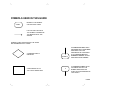
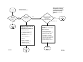
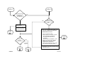
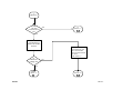
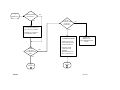
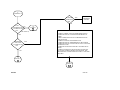
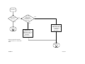
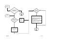
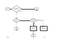
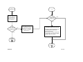
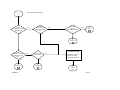
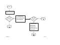
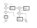
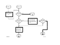
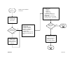
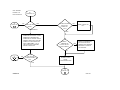
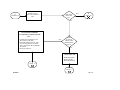
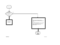
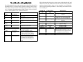
Î GE Fanuc Automation Programmable Control Products Î GE Fanuc Automation P.O. Box 8106 Charlottesville, VA 22906 Series 90 TM–70 GENIUSTM Bus Controller and GENIUS I/O System GFZ–0087 Troubleshooting Guide Î GE Fanuc Automation Programmable Control Products Series 90 TM–70 GENIUSTM Bus Controller and GENIUS I/O System Troubleshooting Guide GFZ–0087 January 1994 Notice Safety Considerations This document is based on information available at the time of its publication. While efforts have been made to be accurate, the information contained in this document does not purport to cover all details or variations in hardware and software, nor to provide for every contingency in connection with installation, operation and maintenance. This document may describe features not present in all hardware and software systems. GE Fanuc Automation assumes no obligation of notice to holders of this document with respect to changes subsequently made. General Warnings When Troubleshooting GE Fanuc Automation makes no representation or warranty, expressed, implied, or statutory with respect to, and assumes no responsibility for the accuracy, completeness or usefulness of the information contained in this document. No warranties of merchantability of fitness for purpose shall apply. Never reach into a machine to operate a switch since unexpected motion could occur, causing injury. The following are trademarks of GE Fanuc Automation North America, Inc. Always remove power before inserting or removing modules, or before connecting I/O cabling. ÁÁÁÁÁÁÁ ÁÁÁÁÁÁÁÁ ÁÁÁÁÁ ÁÁÁÁÁÁÁ ÁÁÁÁÁÁÁÁ ÁÁÁÁÁ ÁÁÁÁÁÁÁ ÁÁÁÁÁÁÁÁ ÁÁÁÁÁ ÁÁÁÁÁÁÁ ÁÁÁÁÁÁÁÁ ÁÁÁÁÁ ÁÁÁÁÁÁÁ ÁÁÁÁÁÁÁÁ ÁÁÁÁÁ ÁÁÁÁÁÁÁ ÁÁÁÁÁÁÁÁ ÁÁÁÁÁ Alarm Master PROMACRO GEnet Series 90 Modelmaster ProLoop Workmaster CIMSTAR Series Six Logicmaster CIMPLICITY 90–ADS Series Three CIMPLICITY PowerTRAC Genius Power TRAC Helpmate CIMPLICITY Series One Genius VuMaster Series Five Copyright 1993 GE Fanuc Automation North America, Inc. All Rights Reserved. Stand clear of controlled equipment when power is applied. If the problem is intermittent, sudden unexpected machine motion could occur, causing injury. Also reference NFPA 70E Part II for additional guidelines for safety practices. Remove all electrical power at the Main Power Disconnect to ensure total power removal. Preface This guide describes a logical sequence for troubleshooting your Series 90–70 Genius Bus Controller, communications between the 90–70 GBC and attached Genius blocks, and the installed Genius cable plant. The Series 90–70 PLC is a member of the Series 90TM family of programmable logic controllers from GE Fanuc Automation. Revisions to this Troubleshooting Guide This is the first release of this Troubleshooting Guide. Genius TM I/O Discrete and Analog Blocks User’s Manual (GEK–90486–2) Genius TM I/O PCIM User’s Manual (GFK–0074) Genius TM I/O PowerTRAC Block User’s Manual (GFK–0450) Genius TM I/O High Speed Counter User’s Manual (GFK–0415D) Series 90 TM–30 Genius Communications Module User’s Manual (GFK–0412) Related Publications Series 90 TM–70 Programmable Controller Installation Manual (GFK–0262). Logicmaster TM 90–70 Programming Software User’s Manual (GFK–0263) Series 90 TM–70 Programmable Controller Reference Manual (GFK–0265) Series 90 TM–70 PLC Genius TM Bus Controller User’s Manual (GFK–0398) Genius TM I/O System and Communications User’s Manual (GEK–90486–1) Series 90 TM–30 Enhanced Genius Communications Module User’s Manual (GFK–0695) We Welcome Your Comments and Suggestions At GE Fanuc Automation, we strive to produce quality technical documentation. After you have used this troubleshooting guide, please take a few moments to write us with your comments and suggestions. Our address is: Manager Technical Publications, GE Fanuc Automation. PO Box 8106, Charlottesville, VA 22906 Drake C. Fink Sr. Staff Systems Engineer Using this Guide This guide directs you to use the Genius Hand Held Monitor (HHM) and the Series 90–70 Fault Tables to troubleshoot your Series 90–70 Genius Bus Controller and the attached Genius bus system. If you are unfamiliar with the operation of the HHM, refer to GFK–0121, Genius Hand Held Monitor Data Sheet and GEK–09486–2, Genius I/O Discrete and Analog Blocks User’s Manual. For information on using the HHM with the PowerTRAC and High Speed Counter Blocks, refer to the manuals for those devices: GFK–0405, Genius PowerTRAC Block and GFK–0415, Genius I/O High Speed Counter. If you are unfamiliar with accessing and interpreting the Series 90–70 I/O Fault Table, refer to GFK–0263, Logicmaster 90–70 Programming Software User’s Manual and GFK–0265, Series 90–70 Programmable Controller Reference Manual. Sometimes solving one problem reveals another problem. Therefore, when this guide concludes that a problem seemingly is resolved, you are directed to reverify the condition of the system. When you resolve a problem with a Genius device, also verify that the Genius Bus Controller functions properly. Similarly, when you resolve a problem with the Genius Bus Controller, also verify that all Genius devices are functioning as you expect. This Guide does not apply to troubleshooting Genius Modular Redundancy systems. Abbreviations used in this Guide include: BTM ... Bus Transmitter Module (IC697BEM713) BRM ... Bus Receiver Module (IC697BEM711) GBC ... Genius Bus Controller (IC697BEM731) HHM ... Genius Hand Held Monitor LM90 ... Logicmaster 90–70 SBA ... Serial Bus Address; same as device number The next page describes the symbols used in this Troubleshooting Guide. |__ __|__ __| SYMBOLS USED IN THIS GUIDE START BEGIN AT THIS SYMBOL ON THE FIRST CHART. FOLLOW THE PATH WITH THE CORRECT ANSWER IN THE DIRECTION OF THE ARROW SYMBOLS USED THROUGHOUT THE GUIDE ARE GEOMETRICALLY CODED A DIAMOND ASKS A QUESTION 5 (PAGE 6) 3 A RECTANGLE TELLS YOU TO DO SOMETHING A NUMBERED BUBBLE WITH AN ARROW INTO THE BUBBLE INDICATES THAT THE PROCEDURE IS CONTINUED AT A CORRESPONDINGLY NUMBERED BUBBLE ON THE INDICATED PAGE NUMBER. A NUMBERED BUBBLE WITH AN ARROW OUT OF THE BUBBLE INDICATES THE START OF A PROCEDURE ON THAT PAGE.I USING |__ __|__ __| ÁÁÁÁÁ ÁÁÁÁÁ ÁÁÁÁÁ ÁÁÁÁÁÁÁÁ ÁÁ ÁÁÁÁÁÁÁÁ ÁÁÁÁÁÁÁÁÁÁ ÁÁÁÁÁÁÁÁ ÁÁÁÁÁÁÁÁ ÁÁÁÁÁÁÁÁ ÁÁÁÁÁÁÁÁ ÁÁÁÁÁÁÁÁ ÁÁÁÁÁÁÁÁ ÁÁÁÁÁÁÁÁ ÁÁÁÁÁ ÁÁ ÁÁÁÁÁÁÁÁÁ Á ÁÁÁÁÁ ÁÁÁÁÁÁÁÁÁ ÁÁÁÁÁÁÁÁÁ ÁÁÁÁÁ ÁÁÁÁÁÁÁÁÁ ÁÁÁÁÁÁÁÁÁ ÁÁÁÁÁÁÁÁÁ ÁÁÁÁÁÁÁÁÁ ÁÁÁÁÁÁÁÁÁ ÁÁÁÁÁÁÁÁÁ ÁÁÁÁÁÁÁÁÁ ÁÁÁÁÁÁÁÁÁ ÁÁÁÁÁÁÁÁÁ ÁÁÁÁÁÁÁÁÁ ÁÁÁÁÁÁÁÁÁ ÁÁÁÁÁ Á ÁÁÁÁÁ ÁÁÁÁÁ ÁÁÁÁÁ START IS UNIT OK LED CONTINUOUSLY ON? YES 8 (PAGE 6) GENIUS BLOCK TROUBLESHOOTING NO IS UNIT OK LED BLINKING RYTHMICALLY? YES NO ERRATIC OR OFF UNIT OK LED INDICATES INSUFFICIENT POWER OR BLOCK FAILURE: · ENSURE BLOCK POWER IS WITHIN RANGE & PROPERLYCONNECTED. (SEE NOTE 1.) · CYCLE POWER TO BLOCK. · IF RTD, CURRENT SOURCE ANALOG OR THERMOCOUPLE BLOCK. SEE NOTE 2. PAGE 1 (Refer to the Preface for information on safety considerations, related publications and the symbols used in this guide.) 14 (PAGE 10) ÁÁÁÁÁÁÁÁÁÁ ÁÁÁÁÁÁÁÁÁÁ ÁÁÁÁÁ ÁÁÁÁÁÁÁÁÁÁ ÁÁÁÁÁÁÁÁÁÁÁ ÁÁÁÁÁÁ ÁÁÁÁÁÁÁÁÁÁ ÁÁÁÁÁ ÁÁÁÁÁÁÁÁÁÁ ÁÁÁÁÁÁÁÁÁÁ ÁÁÁÁÁÁÁÁÁ Á ÁÁÁÁÁÁÁÁÁ ÁÁÁÁÁÁÁÁÁ ÁÁÁÁÁÁÁÁÁ ÁÁÁÁÁÁÁÁÁ ÁÁÁÁÁÁÁÁÁ ÁÁÁÁÁÁÁÁÁ ÁÁÁÁÁÁÁÁÁ ÁÁÁÁÁÁÁÁÁ ÁÁÁÁÁÁÁÁÁ ÁÁÁÁÁÁÁÁÁ ÁÁÁÁÁÁÁÁÁ ÁÁÁÁÁ Á ÁÁÁÁÁ ÁÁÁÁÁ ÁÁÁÁÁ ARE UNIT OK & I/O ENABLED LEDS BLINKING SYNCHRONOUSLY? NO 2 (PAGE 2) (SEE NOTE 4) YES NO CPU COMMUNICATIONS OR SBA CONFLICT: · VERIFY HHM SBA IS UNUSED BY ANY OTHER DEVICE ON THE BUS. · USE HHM TO ASSIGN BLOCK AN UNUSED SBA. CHANGE BLOCK SBA IN LM90 CONIFG AND STORE CONFIG TO PLC. 3 (PAGE 3) GBC70A GFZ-0087 ÁÁÁÁÁ ÁÁÁÁÁ ÁÁÁÁÁ ÁÁÁÁÁ Á 2 (FROM PG 1) 4 (FROM PG 9) ARE UNIT OK & I/O ENABLED LEDS BLINKING ALTERNATELY? NO YES Á ÁÁÁÁÁÁÁ Á ÁÁÁÁÁÁÁ ÁÁÁÁÁ Á ÁÁÁÁÁÁÁ ÁÁÁÁÁÁÁ ÁÁÁÁÁ Á ÁÁÁÁÁ ÁÁÁÁÁÁÁ Á ÁÁÁÁÁÁÁ ÁÁÁÁÁÁÁ ÁÁÁÁÁÁÁ ÁÁÁÁÁÁÁ ÁÁÁÁÁ Á ÁÁÁÁÁ Á ÁÁÁÁÁÁÁÁÁÁ Á ÁÁÁÁÁÁÁÁÁÁ ÁÁÁÁÁ INDICATES: · FORCED CIRCUIT · CIRCUIT FAULT 11 (PAGE 8) IS CIRCUIT FAULT INTENTIONAL? NO 6 (PAGE 5) PAGE 2 YES IGNORE FAULT START (PAGE 1) ÁÁÁÁÁÁÁ Á ÁÁÁÁÁÁÁ ÁÁÁÁÁÁÁ ÁÁÁÁÁÁÁ ÁÁÁÁÁÁÁ ÁÁÁÁÁÁÁÁÁÁÁ Á ÁÁÁÁÁÁÁÁÁÁÁ ÁÁÁÁÁÁÁÁÁÁÁ ÁÁÁÁÁÁÁÁÁÁÁ ÁÁÁÁÁÁÁÁÁÁÁ Á ÁÁÁÁÁÁÁÁÁÁÁ ÁÁÁÁÁÁÁÁÁÁÁ ÁÁÁÁÁÁÁÁÁÁÁ ÁÁÁÁÁÁÁÁÁÁÁ ÁÁÁÁÁÁÁÁÁÁÁ ÁÁÁÁÁÁÁÁÁÁÁ ÁÁÁÁÁÁÁÁÁÁÁ ÁÁÁÁÁÁÁÁÁÁÁ YES IS I/O ENABLED LED CONTINUOUSLY ON? NO OFF I/O ENABLED LED INDICATES NO BUS COMMUNICATION OR DISABLED OUTPUTS: · CYCLE POWER ON GBC · VERIFY BLOCK IN LM90 CONFIG: – HAS SAME SBA AS BLOCK – HAS PROPER REFERENCE ADDRESS – HAS OUTPUTS ENABLED = YES · VERIFY CPU IS RUN/ENABLED · VERIFY BUS IS INTACT AND TERMINATED PROPERLY. · VERIFY BAUD RATE OF GBC AND ALL BLOCKS ARE THE SAME. · BLINKING UNIT OK LED INDICATES CIRCUIT FAULT GBC70B 5 (PAGE 4) ÁÁÁÁÁ ÁÁÁÁÁ ÁÁÁÁÁ ÁÁÁÁÁ ÁÁÁÁÁÁÁ Á ÁÁÁÁÁÁÁ ÁÁÁÁÁÁÁ ÁÁÁÁÁÁÁ ÁÁÁÁÁÁÁ ÁÁÁÁÁÁÁ Á ÁÁÁÁÁÁÁ ÁÁÁÁÁÁÁ ÁÁÁÁÁÁÁ ÁÁÁÁÁÁÁ ÁÁÁÁÁÁÁ Á ÁÁÁÁÁÁÁ ÁÁÁÁÁÁÁ ÁÁÁÁÁÁÁ ÁÁÁÁÁÁÁ Á ÁÁÁÁÁ Á ÁÁÁÁÁ ÁÁÁÁÁ 3 (FROM PG 1) IS GBC CH1 LED CONTINUOUSLY ON? NO YES ENSURE BLOCK POWER IS WITHIN RANGE IS PROBLEM CORRECTED ? YES START (PAGE 1) PAGE 3 NO ÁÁÁÁÁ ÁÁÁÁÁÁ ÁÁÁÁÁ 15 (PAGE 11 ) ÁÁÁÁÁÁÁ ÁÁ ÁÁÁÁÁÁÁ ÁÁÁÁÁÁÁ ÁÁÁÁÁÁÁ ÁÁÁÁÁÁÁ ÁÁÁÁÁÁÁ CHECK SBA OF EACH DEVICE ON BUS TO ENSURE NON–DUPLICATION OF SBAs. (SEE NOTE 5.) ÁÁ ÁÁÁÁÁ ÁÁ ÁÁÁÁÁ ÁÁÁÁÁ 14 (PAGE 10 ) GBC70C ÁÁÁÁÁ ÁÁÁÁÁ ÁÁÁÁÁ ÁÁÁÁÁ 5 (FROM PG 2) ÁÁÁÁÁÁÁ ÁÁÁÁÁÁÁ ÁÁÁÁÁÁÁÁ ÁÁÁÁÁÁÁÁ ÁÁÁÁÁÁÁ ÁÁÁÁÁÁÁ ÁÁÁÁÁÁÁÁ Á ÁÁÁÁÁÁÁÁ Á ÁÁÁÁÁÁÁÁ ÁÁÁÁÁÁÁÁ ÁÁÁÁÁÁÁÁ ÁÁÁÁÁÁÁÁ Á Á ÁÁÁÁÁÁÁ Á ÁÁÁÁÁÁÁ ÁÁÁÁÁÁÁ ÁÁÁÁÁÁÁ ÁÁÁÁÁÁÁ Á ÁÁÁÁÁ Á ÁÁÁÁÁ ÁÁÁÁÁ NO ARE BOTH GBC LEDS OFF? YES · CLEAR ANY FAULTS IN PLC I/O FAULT TABLE · POWER CYCLE RACK CONTAINING GBC IS GBC CH1 LED CONTINUOUSLY ON? NO 15 (PAGE 11) PAGE 4 YES ÁÁÁÁÁÁÁ ÁÁÁÁÁÁÁ ÁÁÁÁÁÁÁÁ ÁÁÁÁÁÁÁÁ ÁÁÁÁÁÁÁ ÁÁÁÁÁÁÁ ÁÁÁÁÁÁÁ Á ÁÁÁÁÁÁÁ ÁÁÁÁÁÁÁ ÁÁÁÁÁÁÁ ÁÁÁÁÁÁÁ ÁÁÁÁÁÁÁ ÁÁÁÁÁÁÁ ÁÁÁÁÁÁÁ ÁÁÁÁÁÁÁ ÁÁÁÁÁÁÁ ÁÁÁÁÁ Á ÁÁÁÁÁ ÁÁÁÁÁ ÁÁÁÁÁ IS CPU RUNNING WITH OUTPUTS ENABLED? NO YES BLOCK & GBC NOT COMMUNICATING · VERIFY BLOCK IS INCLUDED IN LM90 CONFIGURATION · ENSURE GOOD CABLING AND PROPER TERMINATION OF BUS. (SEE NOTE 3.) ÁÁÁÁÁÁ ÁÁ ÁÁÁÁÁÁ ÁÁÁÁÁÁ ÁÁÁÁÁÁ ÁÁÁÁÁÁ REFER TO SERIES 90–70 TROUBLESHOOTING GUIDE 7 (PAGE 5) GBC70D ÁÁÁÁÁ ÁÁÁÁÁ ÁÁÁÁÁ Á ÁÁÁÁÁÁÁÁÁÁ Á ÁÁÁÁÁÁÁÁÁÁ ÁÁÁÁÁÁÁÁÁÁ ÁÁÁÁÁÁÁÁÁÁ ÁÁÁÁÁÁÁÁÁÁ ÁÁÁÁÁÁÁÁÁÁ ÁÁÁÁÁÁÁÁÁÁ ÁÁÁÁÁÁÁÁÁÁ ÁÁÁÁÁÁÁÁÁÁ ÁÁÁÁÁÁÁÁÁÁ Á ÁÁÁÁÁÁÁ Á ÁÁÁÁÁÁÁ ÁÁÁÁÁÁÁ ÁÁÁÁÁÁÁ 6 (FROM PG 2) CIRCUIT FAULT PRESENT: · DETERMINE FAULT USING HHM OR I/O FAULT TABLE IN LOGICMASTER 90–70. FAULT REPORTING IN BLOCK MUST BE ENABLED FOR FAULT TO APPEAR IN I/O FAULT TABLE. · CLEAR FAULT USING HHM OR LM90. IS PROBLEM CORRECTED ? YES NO ÁÁÁÁÁ ÁÁÁÁÁ ÁÁÁÁÁ Á ÁÁÁÁÁÁÁ Á ÁÁÁÁÁÁÁ ÁÁÁÁÁÁÁ ÁÁÁÁÁÁÁ ÁÁÁÁÁÁÁ Á ÁÁÁÁÁÁÁ ÁÁÁÁÁÁÁ ÁÁÁÁÁÁÁ ÁÁÁÁÁÁÁ ÁÁÁÁÁÁÁÁÁÁÁ Á ÁÁÁÁÁÁÁÁÁÁÁ ÁÁÁÁÁÁÁÁÁÁÁ ÁÁÁÁÁÁÁÁÁÁÁ ÁÁÁÁÁÁÁÁÁÁÁ ÁÁÁÁÁÁÁÁÁÁÁ ÁÁÁÁÁÁÁÁÁÁÁ ÁÁÁÁÁÁÁÁÁÁÁ Á Á ÁÁÁÁÁ Á ÁÁÁÁÁ ÁÁÁÁÁ 7 (FROM PG 4) CYCLE POWER TO BLOCK. IS PROBLEM CORRECTED ? YES NO POSSIBLE DEFECTIVE BLOCK · REMOVE POWER FROM BLOCK · UNWIRE BLOCK FROM BUS · REPLACE BLOCK. · RECONNECT POWER TO BLOCK · CONFIGURE BLOCK WITH HHM. · REWIRE BLOCK TO BUS. START (PAGE 1) PAGE 5 GBC70E ÁÁÁÁ ÁÁÁÁ ÁÁÁÁ ÁÁÁÁÁÁÁ ÁÁ ÁÁÁÁÁÁÁ ÁÁÁÁÁÁÁ ÁÁÁÁÁÁÁ ÁÁÁÁÁÁÁ ÁÁÁÁÁÁÁ Á 8 (FROM PG 1) ÁÁÁÁÁ ÁÁÁÁÁÁ ÁÁÁÁÁÁ ÁÁÁÁÁ IS I/O ENABLED LED NO CONTINUOUSLY ON? (SEE NOTE 4) YES ARE BOTH YES GBC LEDS CONTINUOUSLY ON? NO ÁÁÁÁ ÁÁ ÁÁÁÁ ÁÁÁÁ ÁÁÁÁ 15 (PAGE 11) PAGE 6 10 (PAGE 8) ÁÁÁÁÁ ÁÁÁÁ ÁÁÁÁÁ ÁÁÁÁ ÁÁÁÁÁÁ ÁÁ ÁÁÁÁ ÁÁÁÁÁ ÁÁÁÁ ÁÁÁÁÁ ÁÁÁÁÁÁÁÁÁÁÁÁ Á ÁÁÁÁÁÁÁÁÁÁÁÁ ÁÁÁÁÁÁÁÁÁÁÁÁ ÁÁÁÁÁÁÁÁÁÁÁÁ ÁÁÁÁÁÁÁÁÁÁÁÁ ÁÁÁÁÁÁÁÁÁÁÁÁ ÁÁÁÁÁÁÁÁÁÁÁÁ ÁÁÁÁÁÁÁÁÁÁÁÁ ÁÁÁÁÁÁÁÁÁÁÁÁ ÁÁÁÁÁÁÁÁÁÁÁÁ ÁÁÁÁÁÁÁÁÁÁÁÁ ÁÁÁÁÁÁÁÁÁÁÁÁ ÁÁÁÁÁÁÁÁÁÁÁÁ ÁÁÁÁ Á ÁÁÁÁ ÁÁÁÁ IS SYSTEM OPERATING OK? YES PROBLEM SOLVED! NO GENERAL TROUBLESHOOTING · VERIFY CORRECT SBA OF PROBLEM BLOCK(S). · VERIFY BLOCK IS CONFIGURED PROPERLY IN LM90. · CHECK OPERATION OF ELECTROMECHANICAL FIELD DEVICE. · VERIFY VOLTAGE IS WITHIN RANGE. · VERIFY BLOCK IS APPROPRIATELY GROUNDED. · VERIFY BLOCK IS CONNECTED TO AN ACTIVE BUS IF BSM IS IN USE. · VERIFY BUS DEVICES AND GBC AT SAME BAUD RATE. · VERIFY NO PHASE A DEVICES ARE ON THE BUS. · IF IN HOT STANDBY MODE, ENSURE THAT THE MASTER BUS CONTROLLER IS AT SBA 31 AND THE BACKUP 9 (PAGE 7) GBC70F ÁÁÁÁÁ ÁÁÁÁÁ ÁÁÁÁÁ ÁÁÁÁÁ ÁÁÁÁÁÁÁ ÁÁ ÁÁÁÁÁÁÁ ÁÁÁÁÁÁÁ ÁÁÁÁÁÁÁ ÁÁÁÁÁÁÁ ÁÁÁÁÁ ÁÁ ÁÁÁÁÁ ÁÁÁÁÁ 9 (FROM PG 6) ARE THE I/O FORCED?* YES NO ÁÁÁÁÁÁÁÁÁ ÁÁÁÁÁÁÁÁÁ ÁÁÁÁÁÁÁÁÁ ÁÁÁÁÁÁÁÁÁÁ ÁÁÁÁÁÁÁÁÁ ÁÁÁÁÁÁÁÁÁ 11 (PAGE 8) * CHECK FOR FORCES WITH LM90 AS WELL AS WITH THE HHM. DO ANY INPUTS OR OUTPUTS OPERATE ON THE BLOCK? NO ÁÁÁÁÁÁÁ Á ÁÁÁÁÁÁÁ ÁÁÁÁÁÁÁ ÁÁÁÁÁÁÁ ÁÁÁÁÁÁÁ ÁÁÁÁÁÁÁ CHECK FOR OVERRIDES WITH HHM AND LM90. IF UNINTENTIONAL, REMOVE. (SEE NOTE 7) YES ÁÁÁÁÁÁÁ Á ÁÁÁÁÁÁÁ ÁÁÁÁÁÁÁ ÁÁÁÁÁÁÁ ÁÁÁÁÁÁÁ ÁÁÁÁÁÁÁ CHECK FOR OVERRIDES WITH HHM AND LM90. IF INTENTIONAL, REMOVE (SEE NOTE 7) ÁÁ Á ÁÁÁÁÁ Á ÁÁÁÁÁ ÁÁÁÁÁ 14 (PAGE 10) PAGE 7 GBC70G ÁÁÁÁÁ ÁÁÁÁÁ ÁÁÁÁÁÁÁÁÁÁ ÁÁÁÁÁ ÁÁÁÁÁÁÁÁÁÁ ÁÁÁÁÁ ÁÁÁÁÁÁÁÁÁÁ ÁÁÁÁÁÁÁÁÁÁÁ Á ÁÁÁÁÁÁÁÁÁÁ ÁÁÁÁÁ Á ÁÁÁÁÁÁÁÁÁÁ ÁÁÁÁÁ ÁÁÁÁÁ ÁÁÁÁÁÁÁÁÁÁ ÁÁ ÁÁÁÁÁ ÁÁÁÁÁ ÁÁ ÁÁÁÁÁ ÁÁÁÁÁÁÁ ÁÁ ÁÁÁÁÁ ÁÁÁÁÁ ÁÁÁÁÁÁÁ ÁÁÁÁÁ Á ÁÁÁÁÁÁÁÁÁÁÁÁ ÁÁÁÁÁ ÁÁÁÁÁÁÁÁÁÁÁÁ ÁÁÁÁÁÁÁ 10 (FROM PG 6) IS I/O ENABLED LED BLINKING RYTHMICALLY? NO 12 (PAGE 9) YES 11 (FROM PG 7) ARE FORCED CIRCUITS INTENDED? NO ÁÁ ÁÁÁÁÁÁ ÁÁ ÁÁÁÁÁÁ ÁÁÁÁÁÁ ÁÁÁÁÁÁ RELEASE FORCED CIRCUIT WITH HHM. PAGE 8 YES DO NOT CLEAR FORCE ÁÁÁÁÁÁÁ ÁÁÁÁÁÁÁ ÁÁÁÁÁÁÁÁ ÁÁÁÁÁÁÁ ÁÁÁÁÁÁÁ ÁÁÁÁÁÁÁÁÁÁ Á ÁÁÁÁÁÁÁÁÁÁ ÁÁÁÁÁÁÁÁÁÁ ÁÁÁÁÁÁÁÁÁÁ Á ÁÁÁÁÁÁÁÁÁÁ ÁÁÁÁÁÁÁÁÁÁ ÁÁÁÁÁÁÁÁÁÁ ÁÁÁÁÁÁÁÁÁÁ Á ÁÁÁÁÁ Á ÁÁÁÁÁ ÁÁÁÁÁ IS PROBLEM CORRECTED ? YES NO POSSIBLE DEFECTIVE BLOCK · REMOVE POWER FROM BLOCK · UNWIRE BLOCK FROM BUS · REPLACE BLOCK. · RECONNECT POWER TO BLOCK · CONFIGURE BLOCK WITH HHM. · REWIRE BLOCK TO BUS. START (PAGE 1) GBC70H ÁÁÁÁÁÁÁÁÁ ÁÁÁÁÁ ÁÁÁÁÁÁÁÁÁ ÁÁÁÁÁÁÁÁÁ ÁÁÁÁÁ ÁÁÁÁÁÁÁÁÁÁ ÁÁÁÁÁ ÁÁÁÁÁÁÁÁÁ ÁÁÁÁÁÁÁÁÁ ÁÁÁÁÁÁÁÁÁ 12 (FROM PG 8) NO IS I/O ENABLED LED BLINKING ERRATICALLY? ÁÁÁÁÁ ÁÁÁÁÁÁ ÁÁÁÁÁ 4 (PAGE 2) (SEE NOTE 4) YES ÁÁÁÁÁÁÁ Á ÁÁÁÁÁÁÁ ÁÁÁÁÁÁÁ ÁÁÁÁÁÁÁ ÁÁÁÁÁÁÁ IS GBC CH1 LED CONTINUOUSLY ON? NO ÁÁÁÁÁ Á ÁÁÁÁÁ ÁÁÁÁÁ 15 (PAGE 11) YES ÁÁÁÁÁÁÁ ÁÁÁÁÁÁÁ ÁÁÁÁÁÁÁÁ ÁÁÁÁÁÁÁ ÁÁÁÁÁÁÁ ÁÁÁÁÁÁÁ Á ÁÁÁÁÁÁÁ ÁÁÁÁÁÁÁ ÁÁÁÁÁÁÁ ÁÁÁÁÁÁÁ IS CPU RUNNING WITH OUTPUTS ENABLED? NO YES REMOVE HHM FROM THE BUS. ÁÁÁÁÁ Á ÁÁÁÁÁ ÁÁÁÁÁ ÁÁÁÁÁÁÁ Á ÁÁÁÁÁÁÁ ÁÁÁÁÁÁÁ ÁÁÁÁÁÁÁ ÁÁÁÁÁÁÁ REFER TO SERIES 90–70 TROUBLESHOOTING GUIDE. 13 (PAGE 10) PAGE 9 GBC70J ÁÁÁÁÁ ÁÁÁÁÁ ÁÁÁÁÁ ÁÁÁÁÁ ÁÁÁÁÁÁÁ Á ÁÁÁÁÁÁÁ ÁÁÁÁÁÁÁ ÁÁÁÁÁÁÁ ÁÁÁÁÁÁÁ Á ÁÁÁÁÁÁÁ Á ÁÁÁÁÁÁÁ ÁÁÁÁÁÁÁ ÁÁÁÁÁÁÁ 13 (FROM PG 9) 14 VERIFY HHM SBA IS UNUSED BY OTHER DEVICES ON THE BUS. IS PROBLEM CORRECTED ? YES ÁÁÁÁÁ Á ÁÁÁÁÁ ÁÁÁÁÁ ÁÁÁÁÁ START (PAGE 1) PAGE 10 NO ÁÁÁÁ ÁÁÁÁ ÁÁÁÁ ÁÁÁÁ ÁÁÁÁÁÁ ÁÁ ÁÁÁÁÁÁ ÁÁ ÁÁÁÁÁÁ ÁÁÁÁÁÁ ÁÁÁÁÁÁ ÁÁ ÁÁÁÁÁÁÁÁÁÁ ÁÁ ÁÁÁÁÁÁÁÁÁÁ ÁÁÁÁÁÁÁÁÁÁ ÁÁÁÁÁÁÁÁÁÁ ÁÁÁÁÁÁÁÁÁÁ ÁÁÁÁÁÁÁÁÁÁ ÁÁÁÁÁÁÁÁÁÁ Á ÁÁ ÁÁÁÁ ÁÁ ÁÁÁÁ ÁÁÁÁ IS PROBLEM CORRECTED ? YES NO ÁÁÁÁÁÁÁÁ ÁÁÁÁÁÁÁÁ Á ÁÁÁÁÁÁÁÁ ÁÁÁÁÁÁÁÁ Á ÁÁÁÁÁÁÁÁ ÁÁÁÁÁÁÁÁ USING HHM CHECK SBA OF EACH DEVICE ON THE BUS TO ENSURE EACH SBA IS UNIQUE. (SEE NOTE 5) POSSIBLE DEFECTIVE BLOCK · REMOVE POWER FROM BLOCK · UNWIRE BLOCK FROM BUS · REPLACE BLOCK. · RECONNECT POWER TO BLOCK · CONFIGURE BLOCK WITH HHM. · REWIRE BLOCK TO BUS. START (PAGE 1) GBC70K ÁÁÁÁÁ ÁÁÁÁÁ ÁÁÁÁÁ ÁÁÁÁÁ ÁÁÁÁÁÁÁÁ Á ÁÁÁÁÁÁÁÁ ÁÁÁÁÁÁÁÁ ÁÁÁÁÁÁÁÁ ÁÁÁÁÁÁÁÁ 15 IS GBC MODULE OK LED BLINKING? GBC TROUBLESHOOTING YES NO ÁÁÁÁÁÁÁÁ ÁÁÁÁÁÁÁÁ ÁÁÁÁÁÁÁÁÁ ÁÁÁÁÁÁÁÁ ÁÁÁÁÁÁÁÁ IS GBC CH1 OK LED CONTINUOUSLY ON? YES NO ÁÁÁÁÁÁÁÁ ÁÁÁÁÁ ÁÁÁÁÁÁÁÁ ÁÁÁÁÁÁÁÁÁ ÁÁÁÁÁÁ ÁÁÁÁÁÁÁÁ ÁÁÁÁÁ ÁÁÁÁÁÁÁÁ ÁÁÁÁÁ Á ÁÁÁÁÁ ÁÁÁÁÁ ÁÁÁÁÁÁÁ ÁÁÁÁÁÁÁ Á ÁÁ ÁÁÁÁÁÁÁ ÁÁÁÁÁÁÁ ÁÁÁÁÁÁÁ Á ÁÁÁÁÁ Á ÁÁÁÁÁ ÁÁÁÁÁ DO LEDS YES BLINK SYNCHRONOUSLY ? YES 19 (PAGE 15) NO 16 (PAGE 13) ÁÁÁÁÁÁÁÁ Á ÁÁÁÁÁÁÁÁ ÁÁÁÁÁÁÁÁ ÁÁÁÁÁÁÁÁ ÁÁÁÁÁÁÁÁ ÁÁÁÁ Á ÁÁÁÁ ÁÁÁÁ IS GBC MODULE OK LED CONTINUOUSLY ON? YES 20 (PAGE 16) PAGE 11 NO ÁÁÁÁÁÁÁ ÁÁÁÁÁÁÁ ÁÁÁÁÁÁÁÁ ÁÁÁÁÁÁÁ ÁÁÁÁÁÁÁ ÁÁÁÁÁ Á ÁÁÁÁÁ ÁÁÁÁÁ IS GBC CH1 OK LED OFF? YES 23 (PAGE 12) NO DEFECTIVE GBC · REMOVE POWER. · REPLACE GBC. · RESTORE POWER. 15 (THIS PAGE) GBC70L ÁÁÁÁÁ ÁÁÁÁÁ ÁÁÁÁÁ ÁÁÁÁÁÁÁÁ Á ÁÁÁÁÁÁÁÁ ÁÁÁÁÁÁÁÁ ÁÁÁÁÁÁÁÁ Á ÁÁÁÁÁÁÁÁ Á ÁÁÁÁÁÁÁÁ ÁÁÁÁÁÁÁÁ ÁÁÁÁÁÁÁÁ 23 (FROM PG 11) VERIFY RACK POWER. LOSS OF IOC FAULT IN I/O FAULT TABLE? NO ÁÁÁÁÁ Á ÁÁÁÁÁ ÁÁÁÁÁ 17 (PAGE 14) ÁÁÁÁÁÁÁÁÁ ÁÁÁÁÁÁÁÁÁ ÁÁÁÁÁÁÁÁÁ Á ÁÁÁÁÁÁÁÁÁ ÁÁÁÁÁÁÁÁÁ ÁÁÁÁÁÁÁÁÁ YES CPU RESET GBC · CYCLE POWER ON RACK. · USING LM90 READ FAULT EXPLANATION AND RESOLVE PROBLEM. ÁÁÁÁÁÁÁÁ ÁÁÁÁÁ ÁÁÁÁÁÁÁÁ ÁÁÁÁÁÁÁÁÁ ÁÁÁÁÁÁ ÁÁÁÁÁÁÁÁ ÁÁÁÁÁ ÁÁÁÁÁÁÁÁ ÁÁÁÁÁÁÁÁ Á ÁÁÁÁÁÁÁÁ ÁÁÁÁÁÁÁÁ ÁÁÁÁÁÁÁÁ ÁÁÁÁÁÁÁÁ ÁÁÁÁÁÁÁÁ ÁÁÁÁÁÁÁÁ ÁÁÁÁÁÁÁÁ ÁÁÁÁÁ Á ÁÁÁÁÁ ÁÁÁÁÁ ARE BOTH GBC LEDS CONTINUOUSLY ON? YES 22 (PAGE 18) NO DEFECTIVE GBC · REMOVE POWER. · REPLACE GBC. · RESTORE POWER. · CONTACT YOUR DISTRIBUTOR OR THE GE FANUC HOTLINE IF LOSS PERSISTS. 15 (PAGE 11) PAGE 12 GBC70M 16 (FROM PG 11) GBC FAILED ON POWER–UP Á ÁÁÁÁÁÁÁ Á ÁÁÁÁÁÁÁ ÁÁÁÁÁÁÁ ÁÁÁÁÁÁÁ ÁÁÁÁÁÁÁ Á ÁÁÁÁÁÁÁ ÁÁÁÁÁÁÁ ÁÁÁÁÁÁÁ ÁÁÁÁÁÁÁ ÁÁÁÁÁÁÁ ÁÁÁÁÁÁÁ Á ÁÁÁÁÁÁÁ ÁÁÁÁÁÁÁ ÁÁÁÁÁÁÁ ÁÁÁÁÁÁÁ ÁÁÁÁÁ Á ÁÁÁÁÁ ÁÁÁÁÁ ÁÁÁÁÁ GBC IN MAIN RACK? NO YES BLANK SLOT BETWEEN CPU & GBC? NO CYCLE POWER ON MAIN RACK. 18 (PAGE 14) PAGE 13 YES ÁÁÁÁÁÁÁ ÁÁÁÁÁÁÁÁ ÁÁÁÁÁÁÁ ÁÁÁÁÁÁÁÁ ÁÁÁÁÁÁÁ ÁÁ ÁÁ ÁÁÁÁÁÁÁÁ ÁÁÁÁÁÁÁ ÁÁ ÁÁÁÁÁÁÁÁ ÁÁÁÁÁÁÁ ÁÁ ÁÁÁÁÁÁÁ ÁÁÁÁÁÁÁÁ ÁÁÁÁÁÁÁÁ ÁÁ ÁÁ ÁÁÁÁÁÁÁÁ ÁÁ ÁÁÁÁÁÁÁÁ ÁÁÁÁÁÁÁÁ ÁÁÁÁÁÁÁÁ ÁÁÁÁÁÁÁÁ Á ÁÁÁÁÁÁÁÁ ÁÁ ÁÁÁÁÁÁÁÁ ÁÁÁÁÁÁÁÁ ÁÁÁÁÁÁÁÁ ÁÁÁÁÁÁÁÁ ÁÁÁÁÁÁÁÁ · VERIFY I/O CHAIN IS INTACT FROM BTM TO BRM. · VERIFY BRM IN EXPANSION RACK HAS OK LED ON. BLANK SLOT BETWEEN GBC AND BRM IN EXPANSION RACK? YES NO BLANK SLOT BETWEEN CPU AND BTM IN MAIN RACK? ÁÁÁÁÁÁÁÁ ÁÁÁÁÁÁÁÁ Á ÁÁÁÁÁÁÁÁ ÁÁÁÁÁÁÁÁ Á ÁÁÁÁÁÁÁÁ ÁÁÁÁÁÁÁÁ · REMOVE POWER. · ELIMINATE BLANK SLOT. · RESTORE POWER. · MODIFY LM90 CONFIGURATION AND STORE TO PLC. NO YES · REMOVE POWER. · ELIMINATE BLANK SLOT. · RESTORE POWER. · MODIFY LM90 CONFIGURATION AND STORE TO PLC. ÁÁ ÁÁÁÁ Á ÁÁÁÁ ÁÁÁÁ ÁÁÁÁ 18 (PAGE 14) GBC70N 17 (FROM PG 12) ÁÁÁÁÁÁÁ Á ÁÁÁÁÁÁÁ ÁÁÁÁÁÁÁ ÁÁÁÁÁÁÁ ÁÁÁÁÁÁÁ CYCLE POWER ON RACK CONTAINING GBC. 18 (FROM PG 13) Á ÁÁÁÁÁÁÁ Á ÁÁÁÁÁÁÁ ÁÁÁÁÁÁÁ ÁÁÁÁÁÁÁ Á ÁÁÁÁÁÁÁ Á ÁÁÁÁÁÁÁ ÁÁÁÁÁÁÁ ÁÁÁÁÁÁÁ Á Á ÁÁÁÁÁÁÁ Á ÁÁÁÁÁÁÁ ÁÁÁÁÁÁÁ ÁÁÁÁÁÁÁ ÁÁÁÁÁÁÁ ÁÁÁÁÁ Á ÁÁÁÁÁ ÁÁÁÁÁ ARE BOTH GBC LEDS ON? YES NO ANY FAULTS IN FAULT TABLES? NO YES ÁÁÁÁÁ ÁÁÁÁÁÁ ÁÁÁÁÁ ÁÁÁÁÁ ÁÁÁÁÁÁÁÁÁ ÁÁÁÁÁÁÁÁÁ Á ÁÁÁÁÁÁÁÁÁ ÁÁÁÁÁÁÁÁÁ Á ÁÁÁÁÁÁÁÁÁ ÁÁÁÁÁÁÁÁÁ 22 (PAGE 18) · USING LM90 READ FAULT EXPLANATION AND RESOLVE PROBLEM. · CLEAR FAULT TABLES. · CYCLE POWER ON ALL RACKS. ÁÁÁÁÁÁ ÁÁ ÁÁÁÁÁÁ ÁÁ ÁÁÁÁÁÁ ÁÁÁÁÁÁ ARE BOTH GBC LEDS ON? NO DEFECTIVE GBC · REMOVE POWER. · REPLACE GBC. · RESTORE POWER. 15 (PAGE 11) PAGE 14 ÁÁÁÁ Á ÁÁÁÁ ÁÁÁÁ 22 (PAGE 18) GBC70P YES SERIAL BUS ADDRESS CONFLICT 19 (FROM PG 11) Á ÁÁÁÁÁÁÁ Á ÁÁÁÁÁÁÁ ÁÁÁÁÁÁÁ ÁÁÁÁÁÁÁ REMOVE BUS CONNECTOR FROM GBC. ÁÁÁÁÁÁÁ Á ÁÁÁÁÁÁÁ ÁÁÁÁÁÁÁ ÁÁÁÁÁÁÁ ÁÁÁÁÁÁÁ ÁÁÁÁÁÁÁ Á ÁÁÁÁÁÁÁ ÁÁÁÁÁÁÁ ÁÁÁÁÁÁÁ ÁÁÁÁÁÁÁ IS GBC ON END OF BUS? YES VERIFY BUS IS TERMINATED WITH CORRECT RESISTORS (SEE NOTE 3). PAGE 15 NO ÁÁÁÁÁÁÁÁ ÁÁÁÁÁÁÁÁ ÁÁÁÁÁÁÁÁÁ Á ÁÁÁÁÁÁÁÁ ÁÁÁÁÁÁÁÁ ÁÁÁÁÁÁÁÁ ÁÁÁÁÁÁÁÁ ÁÁÁÁÁÁÁÁ · VERIFY BUS CONNECTOR HAS JUMPERS ACROSS SERIAL 1 & SERIAL 2. · VERIFY HHM HAS UNIQUE SBA. · VERIFY NO DEVICE ON BUS HAS SAME SBA AS GBC. ÁÁÁÁÁÁÁÁÁÁ ÁÁÁÁÁÁÁÁÁÁ ÁÁÁÁÁÁÁÁÁÁ ÁÁÁÁÁÁÁÁÁÁ ÁÁ ÁÁÁÁÁÁÁÁÁÁ ÁÁÁÁÁÁÁÁÁÁ ÁÁÁÁÁÁÁÁÁÁ ÁÁÁÁÁÁÁÁÁÁ ÁÁÁÁÁÁÁ ÁÁ ÁÁÁÁÁ ÁÁÁÁÁÁÁ ÁÁ ÁÁÁÁÁÁÁ ÁÁÁÁÁÁ ÁÁÁÁÁÁÁ ÁÁÁÁÁ ÁÁÁÁÁÁÁ ÁÁÁÁÁ · VERIFY THAT: – SERIAL 1 – SERIAL 2 – SHIELD IN – SHIELD OUT LINES ARE CONSISTENT THROUGHOUT GENIUS NETWORK. · VERIFY GENIUS NETWORK TERMINATIONS. (SEE NOTE 3) ARE BOTH GBC LEDS ON? YES 22 (PAGE 18) NO ÁÁÁÁÁÁÁÁ ÁÁ ÁÁÁÁÁÁÁÁ ÁÁÁÁÁÁÁÁ ÁÁÁÁÁÁÁÁ ÁÁÁÁÁÁÁÁ ÁÁ ÁÁÁÁÁ ÁÁ ÁÁÁÁÁ ÁÁÁÁÁ DEFECTIVE GBC · REMOVE POWER · REPLACE GBC · RESTORE POWER 15 (PAGE 11) GBC70R GBC PASSED POWER–UP DIAGNOSTICS 20 (FROM PG 11) Á ÁÁÁÁÁ ÁÁÁÁÁÁÁ Á ÁÁ ÁÁÁÁÁÁÁ ÁÁÁÁÁ ÁÁÁÁÁ ÁÁÁÁÁÁÁ ÁÁÁÁÁ ÁÁÁÁÁÁÁ ÁÁÁÁÁÁÁÁÁ Á ÁÁÁÁÁÁÁÁÁ ÁÁÁÁÁÁÁÁÁ ÁÁÁÁÁÁÁÁÁ ÁÁÁÁÁÁÁÁÁ ÁÁÁÁÁÁÁÁÁ ÁÁÁÁÁÁÁÁÁ ÁÁÁÁÁÁÁÁÁ ÁÁÁÁÁÁÁ Á ÁÁÁÁÁ ÁÁÁÁÁÁÁ Á ÁÁÁÁÁ ÁÁÁÁÁ ÁÁÁÁÁÁÁ ÁÁÁÁÁÁÁ ÁÁÁÁÁÁÁ 22 (PAGE 18) ON GBC CH1 LED STATE: OFF BLINKING · VERIFY BUS IS INTACT AND PROPERLY TERMINATED. · VERIFY BUS CONNECTOR IS FIRMLY INSTALLED ON GBC. · VERIFY ALL BUS DEVICES ARE COMPATIBLE. 90–70 GBC DOES NOT SUPPORT PHASE A DEVICES. 21 (PAGE 17) NO IS GBC CH1 OK LED CONTINUOUSLY ON? YES ÁÁÁÁÁÁÁÁÁÁÁÁÁÁÁ ÁÁÁÁÁÁÁÁ Á Á ÁÁÁÁÁÁÁ ÁÁÁÁÁÁÁÁ ÁÁÁÁÁÁÁ Á Á ÁÁÁÁÁÁÁÁ ÁÁÁÁÁÁÁ ÁÁÁÁÁÁÁÁ ÁÁÁÁÁÁÁÁ Á ÁÁÁÁÁÁÁÁ Á ÁÁÁÁÁÁÁÁÁÁÁÁÁÁÁÁ ÁÁÁÁÁÁÁÁ ÁÁÁÁÁÁÁÁÁÁÁÁÁÁÁÁ Á ÁÁÁÁÁÁÁÁÁÁÁÁÁÁÁÁ ÁÁÁÁÁÁÁÁÁÁÁÁÁÁÁÁ ÁÁÁÁÁÁÁÁ Á ÁÁÁÁÁÁ Á ÁÁÁÁÁÁ ÁÁÁÁÁÁ ÁÁÁÁÁÁ ÁÁÁÁÁÁ Á ÁÁÁÁÁ Á ÁÁÁÁÁ ÁÁÁÁÁ IS LM90 CONFIG EQUAL TO CONFIG IN PLC? NO STORE CONFIG TO PLC. YES CONFIG MISMATCH FAULTS IN PLC FAULT TABLE? YES · RESOLVE MISMATCH FAULTS FOR SLOT WHERE GBC RESIDES. · RESTORE CONFIG IF NECESSARY. NO POWER CYCLE RACK CONTAINING GBC. 15 (PAGE 11) PAGE 16 GBC70S ÁÁÁÁÁÁÁ ÁÁÁÁÁ ÁÁÁÁÁÁÁ ÁÁÁÁÁÁÁ Á ÁÁÁÁÁ ÁÁÁÁÁÁÁ ÁÁÁÁÁ ÁÁÁÁÁÁÁ 21 (FROM PG 16) POWER CYCLE RACK CONTAINING GBC. ÁÁÁÁÁÁÁÁÁÁÁ ÁÁÁÁÁÁÁÁÁÁÁ ÁÁÁÁÁÁÁÁÁÁÁ ÁÁÁÁÁÁÁÁÁÁÁ Á ÁÁÁÁÁÁÁÁÁÁÁ ÁÁÁÁÁÁÁÁÁÁÁ ÁÁÁÁÁÁÁÁÁÁÁ ÁÁÁÁÁÁÁÁÁÁÁ ÁÁÁÁÁÁÁÁÁÁÁ ÁÁÁÁÁÁÁÁÁÁÁ EXCESSIVE BUS ERRORS CAUSED GBC TO DROP OFF THE BUS. · POWER OFF OR REMOVE ALL DEVICES ON THE BUS. · RESTORE THEM ONE–BY–ONE UNTIL THE DEVICE CAUSING THE ”EXCESSIVE BUS” ERRORS IS FOUND. · REPLACE DEVICE. ÁÁÁÁÁ Á ÁÁÁÁÁ ÁÁÁÁÁ 15 (PAGE 11) PAGE 17 ÁÁÁÁÁÁÁ ÁÁÁÁÁÁÁ ÁÁÁÁÁÁÁÁ ÁÁÁÁÁÁÁ ÁÁÁÁÁÁÁ ARE BOTH GBC LEDS ON? YES ÁÁÁÁÁ ÁÁÁÁÁÁ ÁÁÁÁÁ 22 (PAGE 18) NO ÁÁÁÁÁÁÁ Á ÁÁÁÁÁÁÁ ÁÁÁÁÁÁÁ ÁÁÁÁÁÁÁ ÁÁÁÁÁÁÁ ÁÁÁÁÁÁÁ ÁÁÁÁÁÁÁ Á ÁÁÁÁÁÁÁ ÁÁÁÁÁÁÁ ÁÁÁÁÁÁÁ ÁÁÁÁÁÁÁ ÁÁÁÁÁÁÁ ÁÁÁÁÁ Á ÁÁÁÁÁ ÁÁÁÁÁ ÁÁÁÁÁ YES DOES I/O FAULT TABLE HAVE ”ERROR RATE” FAULT? NO DEFECTIVE GBC · REMOVE POWER. · REPLACE GBC. · RESTORE POWER. 15 (PAGE 11) GBC70T ÁÁÁÁÁÁ ÁÁÁÁÁÁ ÁÁÁÁÁÁ ÁÁÁÁÁÁ ÁÁ ÁÁÁÁÁÁÁÁÁ ÁÁÁÁÁÁÁÁÁ ÁÁÁÁÁÁÁÁÁ ÁÁÁÁÁÁÁÁÁ ÁÁÁÁÁÁÁÁÁ ÁÁ ÁÁÁÁÁÁÁ ÁÁÁÁÁÁÁ ÁÁÁÁÁÁÁ ÁÁÁÁÁÁÁ ÁÁÁÁÁÁÁ ÁÁÁÁÁÁÁ 22 IS THE SYSTEM OPERATING OK? YES PROBLEM SOLVED! NO Á · REFER TO FOLLOWING PAGE ”ADDITIONAL TROUBLESHOOTING TIPS.” · IF PROBLEMS PERSIST, CALL YOUR LOCAL DISTRIBUTOR OR THE GE FANUC PLC HOTLINE FOR ASSISTANCE. Á ÁÁÁÁÁÁ Á ÁÁÁÁÁÁ ÁÁÁÁÁÁ 15 (PAGE 11) PAGE 18 GBC70U Additional Troubleshooting Tips D If the PLC is in RUN/ENABLED mode, verify all blocks are powered on. Verify all blocks are communicating with the PLC CPU (both LEDs on). If a block is not communicating, the I/O Fault Table will show a Loss of Block fault for that block. D Verify bus is connected to all devices and to the GBC. I/O Fault Table will have a Loss of Block fault for all blocks downstream from a bus break. D Verify with the Hand Held Monitor that all blocks can be monitored from the bus connector on the 90–70 Genius Bus Controller. D Verify the configuration of the block in LM90 Configuration is the same as the block’s configuration with the Hand Held Monitor (i.e., Grouped vs. Input–only, etc.) The PLC Fault Table will show a ”System Configuration Mismatch” (I/O type mismatch, model number mismatch, BCD length mismatch, reference address mismatch). D Verify baud rate of GBC matches the configured baud rate of the blocks. If you change the GBC baud rate and store configuration to the PLC, the GBC must be power cycled for the baud rate to be effective. The I/O Fault Table may have Loss of Block fault if baud rates differ. D If the situation persists, call your distributor or the GE Fanuc Hotline for assistance. Notes and Precautions 1. Supply (input) voltage power tolerances for Genius blocks varies with the type of block (Analog, Digital) and type of voltage (AC, DC). Refer to the data sheet for an individual block for supply voltage tolerances. 2. For Resistive Temperature Detector (RTD), Thermocouple (TC) and Current Source Analog (CSA) blocks only, Unit OK LED off and I/O Enabled LED blinking indicates an electrical assembly/terminal assembly mismatch. For these same blocks, Unit OK off and I/O Enabled LED off or blinking indicates the block is faulty or there is no power to the block. 3. The Genius bus must be terminated with a resistor at each end. No resistor is permitted at any device which is in the middle of the bus, including Genius Bus Controllers. The resistor must match the impedance of the cable. Refer to the cable manufacturer’s data sheet for cable impedance. Bus connections must be secure at each device. Shield In and Shield Out connections must be properly paired: from Shield Out on one device to Shield In on the next device on the bus. The cable must have no breaks. Refer to the Field Service note ”Genius Cable Plant Troubleshooting Tips” for additional information. 4. Unit OK and I/O Enabled LEDs on a block may blink synchronously when the block is being configured by the Hand Held Monitor. In this case, the synchronous blinking is not a fault and may be ignored. 5. When the serial bus address (SBA, also called device number) is being checked, and you have reason to suspect that the SBA is duplicated in another device on the bus, the device being checked must be powered up and disconnected from the rest of the bus while the check is made. 6. When a circuit fault occurs on a block, the I/O enabled LED blinks. You must correct the circuit fault first, then clear the fault. The block latches the circuit fault indication when it occurs. 7. CAUTION: The overrides may be there for a reason. Check before removing them. Troubleshooting Matrix The following table shows the various states of the Unit OK and I/O Enabled LEDs on a Genius block, and the meaning of those states. This matrix and other block troubleshooting information is in Chapter 17, I/O Block Troubleshooting of GEK–90486–2 Genius I/O Discrete & Analog Blocks User’s Manual Volume 2. The following table shows the various states of the Module OK and Channel 1 (CH1) OK LEDs on a Series 90–70 Genius Bus Controller and the meaning of those states. A bus controller’s two LEDs indicate its current operating condition. After startup, both of these LEDs are normally on. ÁÁÁÁÁ ÁÁÁÁÁÁ ÁÁÁÁÁÁÁÁÁÁ ÁÁÁÁÁ ÁÁÁÁÁÁ ÁÁÁÁÁÁÁÁÁÁ ÁÁÁÁÁ ÁÁÁÁÁÁ ÁÁÁÁÁÁÁÁÁÁ ÁÁÁÁÁ ÁÁÁÁÁÁ ÁÁÁÁÁÁÁÁÁÁÁÁÁÁÁ ÁÁÁÁÁ ÁÁÁÁÁÁ ÁÁÁÁÁÁÁÁÁÁ ÁÁÁÁÁÁ ÁÁÁÁÁÁÁÁÁÁ ÁÁÁÁÁ ÁÁÁÁÁÁ ÁÁÁÁÁÁÁÁÁÁ ÁÁÁÁÁ ÁÁÁÁÁÁ ÁÁÁÁÁÁÁÁÁÁ ÁÁÁÁÁ ÁÁÁÁÁÁ ÁÁÁÁÁÁÁÁÁÁ ÁÁÁÁÁ ÁÁÁÁÁÁ ÁÁÁÁÁÁÁÁÁÁÁÁÁÁÁ ÁÁÁÁÁÁ ÁÁÁÁÁÁÁÁÁÁ ÁÁÁÁÁ ÁÁÁÁÁÁ ÁÁÁÁÁÁÁÁÁÁ ÁÁÁÁÁ ÁÁÁÁÁÁ ÁÁÁÁÁÁÁÁÁÁ ÁÁÁÁÁ ÁÁÁÁÁÁ ÁÁÁÁÁÁÁÁÁÁ ÁÁÁÁÁ ÁÁÁÁÁÁ ÁÁÁÁÁÁÁÁÁÁ ÁÁÁÁÁ ÁÁÁÁÁÁ ÁÁÁÁÁÁÁÁÁÁÁÁÁÁÁ ÁÁÁÁÁ ÁÁÁÁÁÁ ÁÁÁÁÁÁÁÁÁÁ ÁÁÁÁÁÁ ÁÁÁÁÁÁÁÁÁÁ ÁÁÁÁÁ ÁÁÁÁÁÁ ÁÁÁÁÁÁÁÁÁÁ ÁÁÁÁÁÁÁÁÁÁ ÁÁÁÁÁ ÁÁÁÁÁÁ ÁÁÁÁÁÁÁÁÁÁ ÁÁÁÁÁ ÁÁÁÁÁÁ ÁÁÁÁÁÁÁÁÁÁ ÁÁÁÁÁÁÁÁÁÁ ÁÁÁÁÁÁÁÁÁÁ ÁÁÁÁÁ ÁÁÁÁÁÁ ÁÁÁÁÁÁÁÁÁÁ ÁÁÁÁÁ ÁÁÁÁÁÁ ÁÁÁÁÁÁÁÁÁÁ ÁÁÁÁÁÁÁÁÁÁ ÁÁÁÁÁ ÁÁÁÁÁÁ ÁÁÁÁÁÁÁÁÁÁ ÁÁÁÁÁ ÁÁÁÁÁÁ ÁÁÁÁÁÁÁÁÁÁ ÁÁÁÁÁ ÁÁÁÁÁÁ ÁÁÁÁÁÁÁÁÁÁ ÁÁÁÁÁ ÁÁÁÁÁÁ ÁÁÁÁÁÁÁÁÁÁ ÁÁÁÁÁ ÁÁÁÁÁÁ ÁÁÁÁÁÁÁÁÁÁ ÁÁÁÁÁ ÁÁÁÁÁÁ ÁÁÁÁÁÁÁÁÁÁ ÁÁÁÁÁ ÁÁÁÁÁÁ ÁÁÁÁÁÁÁÁÁÁ ÁÁÁÁÁ ÁÁÁÁÁÁ ÁÁÁÁÁÁÁÁÁÁ ÁÁÁÁÁ ÁÁÁÁÁÁ ÁÁÁÁÁÁÁÁÁÁ UNIT OK ON I/O ENABLED ON ON OFF ON Blinking BlinkON ing BlinkOFF ing Alternate blinking Synchronous blinking OFF OFF Don’t care or OFF Blinking MEANING Block functioning; CPU communicating Block functioning, No CPU communications for 3 bus scans Block functioning, Circuit forced Circuit fault, CPU communicating Circuit fault, No CPU communications for 3 bus scans Circuit fault, Circuit forced No CPU communications; serial bus address conflict No power to block or block faulty. (For RTD, Thermocouple, and Current–source analog blocks, I/O enabled LED is off. For RTD, Thermocouple, and Current–source analog blocks, this indicates an Electronics assembly/Terminal assembly mismatch. MODULE OK ON CHANNEL 1 OK ON ON OFF ON Blinking OFF OFF ON OFF OFF Blinking Blinking Blinking ON OFF Blinking Blinking MEANING GBC powered on; valid config loaded GBC powered on, no config loaded or slot misconfigured Bus improperly wired or intermittent bus Defective GBC No power to GBC or GBC reset by PLC CPU Defective GBC Defective GBC GBC failed power up; blank slot between GBC and PLC CPU or I/O chain between expansion rack and main rack is broken Serial bus address conflict Genius Cable Plant Troubleshooting One of the reasons for the popularity of the Genius I/O family is the advanced level of diagnostics available on a point–by–point basis. These diagnostics allow for quick identification of block–level hardware and I/O wiring problems, thus minimizing the overall mean time to repair (MTTR) for the control system. These diagnostics do not, however, assist in the troubleshooting of communications problems related to the cable plant, especially in newly installed systems. Here is a list of the troubleshooting tips that have proven to be the most valuable in starting up countless Genius systems around the world. If you have found others, we’d like to know about them! Cable Installation There are a number of cable installation details that should be checked (twice!) if you are having trouble establishing reliable communications on your Genius cable plant : Make sure that the Serial 1 and Serial 2 lines are connected to the correct terminals on each Genius block and/or controller. If even one block has these wires crossed there can be sporadic problems with loss of communications to one or more blocks. Make sure that the Serial 1 and Serial 2 lines are not shorted to each other, to the shield lines, or to ground at any point in the system. Make sure that the Shield In and Shield Out lines are properly connected thoughout the system. It is very important that the Shield Out terminal of the first bus device is connected to the Shield In terminal of the second device and that the Shield Out terminal of the second device is connected to the Shield In terminal of the third device and so forth in a daisy–chain throughout the system. The first device’s Shield In and the last device’s Shield Out terminals should be left un connected. Incorrect wiring of the Shield In and Shield Out terminals can lead to ground loops and noise interference in your communications. Make sure that the Shield In and Shield Out lines are not shorting to each other where they are exposed at each connection point in the network. It is a good idea to insulate at least one if not both of the exposed shield wires with ”spaghetti” tubing so that the critical Shield In and Shield Out isolation is maintained. Check for any splices in the cable plant. Cable splices are NOT recommended because they can cause signal reflections and introduce noise into the system but if they are absolutely necessary then they should be made inside a grounded junction box using a high quality barrier–type terminal strip with screw connections. Mixing of different cable types (or manufacturers) is NOT recommended even for cables with similar specifications. Check for violations of the minimum bend radius for your cable type. If the minimum bend radius specified is exceeded then the signal carrying conductors may not be correctly centered within the shield layer. This can cause signal impedance problems for communication systems like Genius that operate at higher frequencies. Sharp right angle bends should be avoided at all costs. The larger the bend radius, the better in terms of preventing communications problems. Make sure that the overall cable length and baud rate are compatible with the cable type used. Check the table on page 2–2 of GFK–90486D–1 to see if the total cable length in your cable plant is less than the maximum specified for your chosen baud rate. It may be necessary to change cable types, baud rates, or cable length and routing in order to get your cable plant within acceptable guidelines. Be aware that reducing the baud rate can also limit the total number of devices permitted on the bus! Genius Cable Plant Troubleshooting Serial Bus Address Conflicts There can be one and only one device (block, controller, or Hand Held Monitor) on each bus assigned to each Serial Bus Address 0 to 31. If more than one device on the bus has the same Serial Bus Address then the BLOCK OK and I/O ENABLED LEDs on the affected block(s) will blink synchronously. Block Grounding Each Genius block must have a secure and direct connection to ground. This ground must be made using one of the green ground screws on the side of the Terminal Strip. Note that it is NOT acceptable to daisy–chain the ground connection between multiple blocks since ground loops and noise can result. Load Suppression Inductive loads such as solenoids and relays require suppression circuitry to prevent the RFI noise produced by the coils from affecting the Genius block driving that load. This suppression normally takes the form of flyback diodes for DC coils and RC snubbers for AC coils. The suppression devices should be installed at the coil (or as close as possible) and not at the Genius block output point in order to prevent the noise from being coupled into other unprotected wiring circuits that may be routed in parallel. Refer to Chapter 2 of GFK–90486C–2 for specific information on load suppression devices. Genius Bus Device Baud Rates All devices on each Genius bus must have the same baud rate selected (38.4k, 76.8k, 153.6k STD or 153.6k EXT). Even one block or controller set for the wrong baud rate will lead to unpredictable communications. Every block, controller, and Hand Held Monitor connected to the Genius bus must be checked to verify that it is set for the desired baud rate. Termination Resistors Termination resistors are critical for the correct operation of your Genius cable plant. These resistors are needed to absorb and eliminate any echoed or reflected signals can be generated in a communications system operating at high frequencies like those used by Genius. Check to see that the correct termination resistors have been installed in the correct locations. There should be two (and only two!) termination resistors installed in the network with one located at each of the physical ends of the cable plant. It is not necessary to install a termination resistor at the bus controller if it is located in the middle of the cable plant. The termination resistor value for your cable installation will be dependent on the cable type used. See the table on page 2–2 in GFK–90486D–1 for the exact resistor value. Note that these resistors should NOT be of the wirewound variety since this will introduce unwanted inductance into the system. Be advised that the Series Six Genius Bus Controller and the Genius Personal Computer Interface Module (PCIM) each have built–in termination resistors that can be selected or disabled with jumpers. You need to make sure that these jumpers are set correctly for your installation – it is easy to forget about these and accidentally have a third termination resistor (or the wrong value resistor) in your network. One common problem reported during installation is communication errors between the Hand Held Monitor and stand–alone blocks during the initial block configuration process. This occurs because there is no termination to the communications bus connecting the Hand Held Monitor and the block – believe it or not, the coiled HHM cable is long enough to require termination! Add a 75 Ohm resistor across the Serial 1 and Serial 2 terminals of the target block and the errors should disappear. Be sure and remove this resistor once you are done configuring the blocks to prevent over–termination of your cable plant. Genius Cable Plant Troubleshooting ”Divide and Conquer” The troubleshooting tips detailed above presume that all Genius devices connected to the bus are functioning properly and that there is no defective or damaged cable anywhere in the system. While most Genius bus problems are resolved by one of the techniques listed above, there are times when further steps must be taken to find the cause of the communication difficulties. The simplest way to find defective blocks or cable is to use the ”divide and conquer” method. To do this, power down the system, disconnect the bus at some convenient point (ideally at the halfway point), and re– terminate the section with the bus controller. Turn the system power back on and observe the communications performance. If the problem persists on the shortened bus, split it and re–terminate again. Repeat this process until the shortened bus is finally operating correctly. Start adding back one block at a time until the problem appears again. The block and/or the cable section that is added when the problem re– appears should be investigated carefully. The ”problem” block is either defective, mis–wired, has a conflicting bus address or has an incorrect baud rate. It is also possible that there is a problem with the specific sections of cable connected to the block – there may be broken or shorted conductors, insulation problems, bad splices, minimum bend radius violations, or excessive noise sources along the cable path.