1
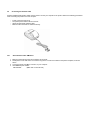
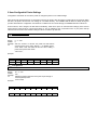
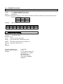
A Higher Level of Precision… A Higher Level of Performance Intell-Print™ Thermal Printer OM7212 User Operation Manual WARNINGS Do not subject your printer to excessive force or shock such as treading on it, dropping it, or hitting it. Do not install your printer in locations with poor ventilation or in locations in which the air contains salt or toxic gases. Do not use your printer at a voltage other than the specified voltage or at frequencies other than the specified frequencies. Only power the printer with the supplied adapter and specified battery. Do not insert or remove the power cable or interface cable by pulling on the cable. Do not drop or insert foreign objects like paper clips, pins, etc. into the equipment. In such case remove the object, if accessible, or contact your reseller for help. Do not attempt to disassemble or modify your printer. Any such unauthorized action will void the warranty and may cause a fire hazard or electric shock. Do not spill or spray any liquids onto the printer. In such case, immediately turn off the power, remove the power supply cable, and contact your reseller for help. Do not plug in your printer to a receptacle and/or power-strip with too many other devices on the same circuit. ELECTRONIC EMISSION NOTICES FEDERAL COMMUNICATIONS COMMISSION (FCC) STATEMENT This equipment has been tested and found to comply with the limits for a Class A digital device, pursuant to Part 15 of the FCC Rules. These limits are designed to provide reasonable protection against harmful interference when operated in a commercial environment. This equipment generates, uses, and can radiate radio frequency energy, and if not installed and used in accordance with the instructions, may cause harmful interference to radio communications. However, there is no guarantee that interference will not occur in a particular installation. If this equipment does cause harmful interference to radio or television reception, which can be determined by turning the equipment off and on, the user is encouraged to try to correct the interference by one or more of the following measures: � � � � Reorient or relocate the receiving antenna. Increase the separation between the equipment and receiver. Connect the equipment into an outlet on a circuit different from that to which the receiver is connected. Consult your authorized reseller or service representative for help. Properly shielded and grounded cables and connectors must be used in order to meet FCC emission limits. Proper cables and connectors are available from OMNIPrint authorized dealers. INDUSTRY CANADA CLASS A EMISSION COMPLIANCE STATEMENT This Class A digital apparatus meets all the requirements of the Canadian Interference-Causing Equipment Regulations. Cet appareil numérique de la classe A respecte toutes les exigences du Règlement sur le matériel brouilleur du Canada. EUROPEAN UNION – EMISSION DIRECTIVE This product is in conformity with the protection requirements of EU Council Low Voltage Directive 73/23/EEC and Electromagnetic Compatibility Directive 89/336/ECC on the approximation of the laws of the member states of the EEC Commission. Intelligent Weighing Technology, Inc. cannot accept responsibility for any failure to satisfy the protection requirements resulting from a non-recommended modification of the product. This product has been tested and found to comply with the limits for Class A Information Technology Equipment according to CISPR 22 / European Standard EN 55022. In a domestic environment this product may cause radio interference in which case the user may be required to take adequate measures. Table of Con tents 1 INTRODUCTION ......................................................................................................7 1.1 Features ......................................................................................................7 2 SPECIFICATIONS .............................................................................................8 2.1 General Specifications .................................................................................8 3 Setting up the printer ..........................................................................................9 3.1 Unpacking....................................................................................................9 3.2 Selecting a Place ........................................................................................9 3.3 Connecting the Power Adapter ............................................................................................................10 3.4 Battery......................................................................................................................................................................10 3.4.1 Operation Without a Battery Pack ................................................................................10 3.4.2 Operation With a Battery Pack ........................................................................................10 3.4.3 Charging procedure .................................................................................................................10 3.4.4 Replacing the Battery Pack.................................................................................................12 3.5 Connecting the Interface Cable ..........................................................................................................13 3.5.1 Serial Interface Cable: OM7212-S.................................................................................13 3.6 Loading Paper ..................................................................................................................................................14 3.7 Attaching the Belt Clip .................................................................................................................................15 4 External Appearance .............................................................................................................................................16 5 Control Panel ...............................................................................................................................................................17 6 Running the Self Test.............................................................................................................................................17 7 Accessories ...................................................................................................................................................................18 8 Communications Interfaces...............................................................................................................................19 8.1 RS232.......................................................................................................................................................................19 8.1.1 Serial Interface Specifications .........................................................................................19 8.1.2 RJ12 Connector Pin Assignment: .................................................................................19 8.2 Infrared (IR) Transmission .......................................................................................................................19 8.2.1 Guidelines for IR Communication...................................................................................19 8.3 Bluetooth ................................................................................................................................................................20 8.3.1 Bluetooth Device Address (BD Address) .................................................................20 8.3.2 Bluetooth Device Name (BD Name) ...........................................................................20 8.3.3 Maximum Simultaneous Connections ........................................................................20 8.3.4 PIN Code ............................................................................................................................................21 8.4 802.11b (Wireless Ethernet) .................................................................................................................21 8.4.1 802.11b Configuration Description ................................................................................21 8.4.2 TCP/IP Protocol Configuration Description ...........................................................21 8.4.3 802.1 1b Network Identification Name .......................................................................22 8.4.4 Name Resolution Issues (Attention: Network Administrators) ..........22 9 User-Configurable Printer Settings ............................................................................................................24 9.1 Sleep Timeout Duration..............................................................................................................................24 9.2 Print Darkness....................................................................................................................................................24 9.3 Select Serial Communication Parameters ..................................................................................25 9.4 Hardware Handshaking..............................................................................................................................25 9.5 XON/XOFF Flow Control...........................................................................................................................26 9.6 802.11b Wireless Network Settings..................................................................................................26 9.7 TCP/IP Protocol Network Settings.....................................................................................................28 9.8 802.11b Wireless Network Name .....................................................................................................29 9.9 Dip Switch Settings........................................................................................................................................29 9.9.1 Baud Rate ..........................................................................................................................................29 9.9.2 Reserved Switches.....................................................................................................................29 9.9.3 Ignore Carriage Return Mode ............................................................................................29 9.9.4 Hex Dump Mode ..........................................................................................................................29 10 Troubleshooting ...........................................................................................................................30 APPENDIX 1 INTERNATIONAL CHARACTERS SET .............................................................................31 1 INTRODUCTION The OM7212 is a thermal line printer designed for portable, wireless applications. 1.1 Features Easy paper loading with clamshell mechanism design Conforming to RS-232C serial Portable, powered by a Lithium-Ion Battery Wireless IrDA Communication (optional) Wireless Bluetooth Communication (optional) Paper out sensor Light weight Belt clip for hands free operation Multiple international character set Automatic sleep mode for battery charge conservation Watch dog software shuts off power to the print head in the case of a paper jam Full 96 ASCII set (plus additional European/Chinese and scientific characters) Optional flash memory for storing logo, etc. Epson ESC/POS emulation Bit mapped graphics with 200 dots per inch resolution 2 SPECIFICATIONS 2.1 General Specifications Print method No. of columns Printing speed No. of dots per line Dot Size Character size (Font Size) Font size IrDA (optional) Bluetooth (optional) WiFi (optional) Cable Interface Emulation Battery Paper Max Print Width Power supply Dimensions (mm) Reliability (MCBF) Weight Safety approvals Operating condition Thermal line printing 32 (Font A) and 42(Font B) 60 mm/sec 384 at 8 dots/mm resolution 0.125 (W) x 0.125 (H) mm 1.125 x 3.0 mm (9 x 24) 1.5 x 3.0 mm (12 x 24) 12 x 24 (Font A) and 9 x 24 (Font B) IrDA V1. 1 standard or proprietary STX/ETX protocol Bluetooth 1.1 compliant 802.1 1b wireless RS-232C serial Epson ESC/POS Lithium-Ion 8.4V / 1 800mA Width 58 ± 0.5 mm Diameter 45 mm (Max) 48 mm 12 VDC ±10% 2 A 85 (W) x 145 (D) x 75 (H) 15 million Lines, 50 million Pulses, 50 km 400 g (0.88 lbs) FCC, CE, UL, cUL 0 to 50 ° C 10 to 80 % RH (Operating) 3 Setting up the printer 3.1 Unpacking The items illustrated below are included in the printer package. If any items are damaged or missing, please contact your dealer for assistance: Printer Paper Roll Power Supply Manual Belt Clip Interface Cable (optional) 3.2 Selecting a Place 1. 2. 3. Protect your printer from excessive heat such as direct sunlight or heaters. Avoid exposing the printer to excessive dust and humidity. Place the printer on a firm, level surface free from intense vibration or shock. 3.3 Connecting the Power Adapter This printer requires an external power supply. An approved Class 2 power supply is required for the operation of this product. 1. 2. 3. 4. Make sure the power switch is turned off. Insert the output plug of the power adapter into the printer DC jack. Plug in the adapter or the power supply’s cord to an outlet. Only use one of the following OMNIPrint adapters: OMPS7205-915-NA OMPS7205-915-EU OMPS7205-1220-SMPS (120 VAC input) (220-240VAC input) (90-240VAC input) Output: 12VDC 2.0A , 2.1mm x 5.5mm female plug , Center positive. 3.4 3.4.1 Battery Operation Without a Battery Pack If your printer has dip switches then the sliding switch in the dip switch well must be set so the actuator is adjacent to the dip switches. If your printer does not have dip switches, and has been specified to operate without a battery, then no configuration is necessary. The printer power must be off before actuating any of the switches in the dip switch well. If your printer does not have dip switches, and has not been specified to operate without a battery, then it must be operated with a battery pack. Actuator adjacent to dip switches 3.4.2 Operation With a Battery Pack If your printer has dip switches then the sliding switch in the dip switch well must be positioned away from the dip switches. The printer power must be off before actuating any of the switches in the dip switch well. If your printer does not have dip switches then no configuration is necessary to operate with a battery. Actuator away from dip switches 3.4.3 Charging procedure The printer is equipped with a lithium-ion battery pack. Although the battery pack is charged when they are shipped from the factory, your unit may have discharged. Please recharge the pack with the appropriate AC adapter before using the printer. Turn the printer off and plug the adapter into an AC outlet and connect the cable to the printer. The battery pack takes 3 hours to become fully charged. NOTES: � Make sure you turn off the power switch before charging the battery pack. � Do not charge the pack longer than 24 hours, or the batteries may deteriorate. � The printer can be used immediately after the adapter is connected. � The room temperature should be between 5 and 40 °C during charging. � With the Bluetooth or WiFi options, the true charge state of the battery can only be determined with the printer’s power turned off. 3.4.4 Replacing the Battery Pack Renew the battery pack if it discharges within an extremely short time. 1. Replace the cell with: Li-ION 8.4V, 1800 mAH, OMNIPrint Part No.: OMBP-7212-18, or Li-ION 8.4V, 2400 mAH, OMNIPrint Part No.: OMBP-7212-24 Use of another cell may present a risk of fire or explosion. Replacement cells can be obtained from OMNIPrint by visiting www.omniprintinc.com. CAUTION: The cell used in this device may present a fire or chemical burn hazard if mistreated. Do not disassemble, heat above 100°C (212°F), or incinerate. 2. Turn the printer off. 3. Turn the printer over. Open the battery lid using the tip of your finger, a coin, etc. Avoid using a sharp object. 4. Take the battery pack out by pulling on the ribbon wrapped around it. 5. Disconnect the battery connector and remove the battery pack. Install the new battery pack and attach the battery connector in the correct direction. Please note that the connectors are keyed to ensure the right polarity is maintained. 6. Attach the battery cover. 7. Dispose of used cell promptly. Keep away from children. Make sure you turn off the power switch. Do not disassemble the battery pack. Hold the connector body not the lead, when disconnecting the battery connector. Do not short-circuit the battery pack terminals. Do not throw the used battery in fire. 3.5 Connecting the Interface Cable Properly shielded serial interface cable must be used to connect your computer to the printer. Observe the following precautions when connecting the printer to the host computer. � � � � 3.5.1 1. 2. 3. 4. Power to the host must be off. The printer power switch must be turned off. Attach the appropriate interface cable. Make sure all connectors are inserted correctly. Serial Interface Cable: OM7212-S Make sure that both the printer and computer are turned off. Serial printers come with an RJ-12 connector. Plug the RJ-12 end of the cable into the printer receptacle, as shown above. Connect the other end, DB9-F connector, to your computer. Use OMNIPrint part number: CBL7205-69F (DB-9 male on the host side) 3.6 Loading Paper Use a paper roll that meets the specifications. Do not use paper rolls that are glued to the core. Make sure data is not being transmitted to the printer while loading paper. 1. 2. 3. 4. 5. 6. 7. 8. Open the printer paper cover by firmly holding the printer in one hand and gently lift the paper cover by applying an equal force on both sides. Remove the old paper roll, if any, by gently removing the spindle from the roll holder. Do not pull the paper out of the printer. Always use the FEED button. Put the spindle inside the new roll’s core and gently insert it on the printer’s roll holder until it snaps in on both ends. Align the paper so it is straight and its core is parallel to the spindle. Make sure the paper is curling up. Pull the paper so that the leading edge of the paper goes at least two inches beyond the printer tear bar. Close the printer paper cover and make sure its snaps in on both ends. Press the FEED button to make sure the roll is properly loaded. If you notice any wrinkles or creases on the edges of the paper try loading the paper again. Tear the excess paper against the serrated edge. NOTE: You do not have to use the spindle but it is recommended in order to: 1) Reduce tension on the paper; 2) Stop the roll from rattling inside the cover in portable applications. 3.7 Attaching the Belt Clip Please follow the following procedure if you desire to use the included belt clip: � � � � � Turn the printer over. Hold the printer such that the IrDA window is towards you. You will notice two rectangular holes in the middle of the printer case. Hold the belt clip facing the outside surface. Insert the belt clip’s front tab perpendicularly into the hole closer to you. Lower the belt clip until its other tab goes inside the second hole. The clip must be in a horizontal position parallel to the printer bottom case. Press the belt clip’s edge away from you towards you until it snaps in. 4 External Appearance 5 Control Panel The control panel features one button and three LEDs POWER SWTICH: The power switch is a slide type located in the rear of the printer. Use this switch to power the printer, reset, or get the printer out of sleep mode. FEED BUTTON: Press the FEED button once to advance one line or hold down for continuous paper feeding. POWER LED: Green LED, when blinking, indicates power is on. Red LED, when blinking, indicates low battery. ERROR LED: Red LED, when blinking, indicates an error condition. The most common error conditions are out of paper, cover open. CHARGER LED: a) Green indicates the battery if fully charged. b) Red indicates battery is charging. c) When the adapter is not plugged in the Charger LED will be off. 6 Running the Self Test Any time you want to check the performance of your printer you can run the self test as follows: 1. 2. 3. While holding down the FEED button, turn the printer on. The printer prints the model name, and firmware revision installed along with other configuration information. The printer will automatically stop printing at the completion of the self test. If the FEED button is pressed again, a character pattern will be printed. If the printing the character test pattern is not desired, cycle the power on the printer to resume normal operation. NOTE: THE PRINTER MAY GO OFF LINE AND WILL NOT COMMUNICATE WITH THE HOST WHILE IT IS IN SELF TEST MODE. 7 Accessories 1) Paper: 58mm+/-0.5mm(width) , 1.75” max(roll diameter) , 85 microns (thickness) TP-60-70 2) Interface Cable: 6 foot long, shielded cable with molded connectors. CBL7205-625F Serial cable w/ DB-25F host side CBL7205-69F Serial cable w/ DB-9F host side 3) Power Supply: Output: 12VDC 2.0A , 2.1mm x 5.5mm female plug , center positive. OMPS7205-915-NA 120VAC input OMPS7205-9 15-EU 220-240VAC input OMPS7205-1220-SMPS 90-240VAC input 8 Communications Interfaces The standard communications interface for the OM7212 printer is RS-232. The printer uses an RJ12 connector for this serial interface. 8.1 RS232 8.1.1 Serial Interface Specifications Data Transmission Method: Baud Rate: Word Format: Hardware Handshaking: 8.1.2 Asynchronous serial interface User selectable 2400 to 115200 Start bit 1 bit Data Length 7 or 8 bits Parity Odd, Even, None Stop bit 1 bit Signal Polarity: MARK: Logic “1” (-10V) SPACE: Logic “0” (+10V) Mark: Data transmission not possible Space: Data transmission possible RJ12 Connector Pin Assignment: FUNCTION F-GND TXD RXD RTS DSR DTR 8.2 PIN No. 1 2 3 4 5 6 INPUT-OUTPUT GND OUT IN OUT IN OUT Infrared (IR) Transmission If your OM7212 is configured with the optional IR transceiver, it is capable of communicating via an IrDA 1.1 connection. To determine if your printer is configured with an IR transceiver, print a test label as outlined in section 6 and look for the section labeled “IR Port”. 8.2.1 � � � Guidelines for IR Communication Turn the printer on. Place the host within 1 m (39 inches) of the printer’s IR port. Make sure the host’s transmitter/receiver is within a 15 degree angle from the center axis of the printer lens. Please refer to the drawing below: 8.3 Bluetooth If your OM7212 is configured with the optional Bluetooth radio, it is capable of communicating via the Bluetooth Serial Port Profile (SPP). The Bluetooth SPP is a wireless serial port cable replacement connection. To determine if your printer is configured with a Bluetooth radio, print a test label as outlined in section 6 and look for the section labeled “Bluetooth”. 8.3.1 Bluetooth Device Address (BD Address) Each printer configured with the Bluetooth options, contains a unique address used to establish a Bluetooth connection. The BD Address for each printer is printed on the test label under the Bluetooth section. Follow the instructions in section 6 to print a test label. 8.3.2 Bluetooth Device Name (BD Name) The Printers are configured with a friendly name to help identify the correct printer when making a Bluetooth connection. The BD Name for each printer is OM7212 – nnnn where nnnn is the last four digits of the printer’s serial number. e.g. If the printer’s serial number is 123456789, the BD Name will be OM7212 – 6789. 8.3.3 Maximum Simultaneous Connections The OM7212 will allow only one Bluetooth SPP connection at a time. 8.3.4 PIN Code Each Bluetooth enabled OM7212 contains a PIN code to help ensure you connect to the printer that you intend to. When establishing a Bluetooth connection for the first time, you will be prompted by the host device to enter the PIN of the OM7212. The PIN is the last four digits of the printer’s serial number. e.g. If the printer’s serial number is 123456789, the PIN will be 6789. 8.4 802.11b (Wireless Ethernet) If your OM7212 is configured with the optional 802.11b wireless Ethernet radio component, the printer can be used in an 802.11b wireless network in a variety of configurations. Supported modes of operation include: Access Point (existing infrastructure); Ad-hoc / peer-to-peer; 64 and 128 bit WEP encryption as well as unencrypted data transfer; Static and Dynamic IP address allocation. 8.4.1 802.11b Configuration Description This section describes the wireless network configuration process to allow the printer to participate on your new or existing wireless network. First, it is necessary to determine what network mode the printer will need to operate in. If there will be a wireless router or other device acting as an Access Point (AP) on the intended wireless network, then the printer needs to be configured for AP mode. If the intended network includes only workstations (such as a collection of laptop computers), or you do not currently have a wireless network, then the printer needs to be configured for Ad-hoc mode. The mode can be altered as needed as the network environment evolves. Both modes require an SSID to identify the wireless network to all participants. In the case of an existing network, you will need to set this to match the network’s SSID. Additionally, the degree of encryption used needs to be determined as well. For existing networks, these settings must be configured to match the intended network. If setting up a new network, the encryption settings can be configured as needed for your purposes. These settings include Encryption Mode, at least one Encryption Key, and Use Encryption Key Entry. Finally, if using Ad-hoc mode, the network channel needs to be set as well for the desired network (For AP mode, the channel is automatically acquired from the AP during the connection negotiation process). 8.4.2 TCP/IP Protocol Configuration Description All 802.1 1b wireless Ethernet communications utilize the TCP/IP protocol suite for operation on the network. The printer uses TCP port 9100 for raw data transfer. If your network will have a DHCP-enabled server or router on it (most wireless routers can be configured to provide DHCP services), the simplest and most flexible configuration available for the printer is to enable dynamic IP Address Allocation via DHCP. If there is no DHCP server available, or you have a need for a statically assigned IP on your network, then you must configure the IP Address Allocation setting to static. If using static allocation mode, three additional settings must also be configured: Static IP Address, Static IP Address Mask, and Static IP Gateway. These settings will all depend on how the network is currently configured, and as such, cannot be enumerated here. Contact your network administrator for more information about configuring a static IP address for your network. 8.4.3 802.11b Network Identification Name In order to provide a means of identification on the wireless network, a setting is available to assign a name or other personalized string of up to 15 characters in length. This will allow you to refer to printers uniquely by name on the network. The printer provides a default name of “OM7212”. If two or more printers, having the same assigned network name (whether by using the default setting or having similar name assignments, as above), are active at the same time on the same network, additional name modification steps are taken to ensure a unique name to each. For every printer with the same name that joins the network after the first, an additional numerical suffix is added to the name. For example, using the default name “OM7212”: the first printer joining the network will use the name “OM7212”; the second will have its name appended to “OM7212-2”; the third, “OM7212-3”, etc. Because this name modification technique is dynamic in nature, the resulting network name that a printer ends up using can vary based on the presence or absence of other like-named printers, every time the printer joins the network. Setting unique names for each printer is therefore recommended if using more than a single printer on the same network. 8.4.4 Name Resolution Issues (Attention: Network Administrators) There are two options available when it comes to name resolution with OmniPrint printers. The first, and probably most widely used, is broadcast name resolution by way of NetBIOS over TCP/IP (NBT), courtesy of its Name Management Protocol (NMP). Smaller Windows-based networks without a local DNS server will use this option for both static and dynamic IP address allocation modes. This mode is more flexible than using the DNS solution (described below), as it requires no additional network configuration, but the broadcast mechanism limits the scope of the printer to a single network subnet. The second option requires a local DNS server, and works best with the static IP address allocation mode, but can be made to work with Dynamic-DNS, if a DHCP server-side update mechanism is available – the printer cannot do its own Dynamic-DNS update. In this case, a network administrator needs to configure the DNS server to provide a valid name-to-IP mapping for the intended printers. Note that this mode is less flexible than the first option, but allows the printer to be used in a larger-scaled network. This configuration is entirely client (and DNS server)-specific, as the printer has no need for name resolution itself; the client machines are the ones who need to resolve the printer’s name. For Windows, the determining factors are whether or not the client machine uses a DNS server to do name resolution, and then whether the DNS server has an entry to resolve the specified printer’s name. If these are both true, then DNS name resolution will be used. If either of these are not true, then the client Windows machine will resort to the broadcast resolution method. Other operating systems may require the DNS method to be used, as they may not have the capability to do broadcast name resolution. Note: NetBIOS name server (NBNS; WINS in Windows) support currently does not exist in OmniPrint printers. Windows is always able to use broadcast resolution as a lowest common denominator, and the presence of a NBNS/WINS server is never guaranteed. 9 User-Configurable Printer Settings Configuration commands are sent to the printer to change the printer’s non-volatile settings. After sending the desired sequence of command functions to the printer, allow the printer to remain idle for two seconds. Within that time, the printer will save the new settings to non-volatile memory. The POWER LED will blink red briefly during this process. Note that if the configuration commands do not differ from the current settings, the POWER LED will not blink red. Some functions, when changed, will take effect immediately, while others (such as communication settings) won't become active until the printer power is cycled off and back on. This is notated for each command function. If your printer has dip switches then the serial communication settings must be set with the dip switches. 9.1 Sleep Timeout Duration ESC c c 3 , n , Range: Default: Descripti on: 0 ~ n ~ 255 0 Sets the number of minutes the printer will wait before entering power saver mode. Setting n = 0 disables powersaver mode. Note that data will be lost when waking a printer from power saver mode. <Esc>cc3, 1, Example : ASCII Hex Dec 9.2 ESC 1B 27 c 63 99 c 63 99 3 33 51 , 2C 44 1 31 49 , 2C 44 Print Darkness ESC c c 4 , n , Range: Default: Descripti on: 20 ~ n ~ 150 100 Adjusts the relative darkness of the print as percentage of nominal (default) value. <Esc>cc4,80, Example : ASCII Hex ESC 1B c 63 c 63 3 33 , 2C 8 38 0 30 , 2C Dec 27 99 99 51 44 56 48 44 9.3 Select Serial Communication Parameters ESC c c 32 , BaudRate ,Parity,DataBits,StopBits Range: BaudRate = 2400, 4800, 9600, 19200, 38400, 57600, or 115200 Parity = N (no parity), E (even parity), or O (odd parity) 7 ~ DataBits ~ 8 1 ~ StopBits ~ 2 Default: 19200,N,8,1 Description: Sets the serial communication parameters. The printer must be reset for the new settings to take effect. If your printer has dip switches then the serial communication settings must be set with the dip switches. Example: <Esc>cc32,19200,N,8,1, ASCII Hex Dec ESC 1B 27 C 63 99 c 63 99 3 33 51 2 32 50 ASCII Hex Dec 2 32 50 0 30 48 0 30 48 , 2C 44 N 4E 78 ASCII Hex Dec 1 63 99 , 2C 44 9.4 , 2C 44 , 2C 44 1 31 49 8 38 56 9 39 57 , 31 49 Hardware Handshaking ESC c c 33 , n , Range: Default: Descrip tion: n = 0 disables hardware handshaking n = 1 enables hardware handshaking 1 (enabled) Determines whether or not the printer uses hardwired signals to control the data flow into the printer’s serial port. <Esc>cc33, 1, Exampl e: ASCII Hex Dec ESC 1B 27 c 63 99 c 63 99 3 33 51 3 33 51 , 2C 44 1 31 49 , 2C 44 9.5 XON/XOFF Flow Control ESC c c 34 , n , Range: n = 0 disables XON/XOFF flow control n = 1 enables XON/XOFF flow control Default: 0 (disabled) Description: Determines whether or not the printer uses XON and XOFF characters to control the data flow into the printer’s serial port. Decimal HEX XON 17 11 XOFF 19 13 Example: ASCII Hex Dec <Esc>cc34, 1, ESC 1B 27 c 63 99 c 63 99 3 33 51 4 34 52 , 2C 44 1 31 49 9.6 802.11b Wireless Network Settings ESC c c 48 , Function , P1 , [ P2 ] Function: 1 : Set Network Mode Paramete 1 (P1) rs: P1 0: Ad-hoc / peer-to-peer mode Range: 1: AP (Access Point) / infrastructure mode 1 Default: The network operating mode for the 802.1 1b Descripti connectivity. <Esc>cc48, 1,0, on: Example: Function: Parameters: P1 Range: Default: Description: Example: 2 : Set SSID 1 (P1) (1 – 32 character string): the SSID string to use “default” The SSID for the 802.11b connectivity. <Esc>cc48,2,“MyNewW ifiNetwork” , 2C 44 Functio n: Parame ters: P1 Range: Default: Descrip tion: 3 : Set Channel (Ad-hoc mode) 1 (P1) 1 – 14: the channel # to use 6 The channel # to use for the 802.1 1b connectivity in ad-hoc mode. <Esc>cc48,3,9, Exampl e: Function: 4 : Set Encryption Mode Parameters: 1 (P1) P1 Range: 0: No encryption 2: WEP 64-bit encryption 3: WEP 128-bit encryption Default: 0 Description: The encryption protocol to use for the 802.1 1b connectivity. Example: <Esc>cc48,4,3, Function: P1 Range: P2 Range: 5 : Set Encryption Key Parameters: 2 (P1, P2) 1 - 4: The encryption key entry # to set (10 character hex string): the WEP 64-bit key (26 character hex string): the WEP 128-bit key (0 characters): clears key Default: <none> Description: Sets one of four possible encryption keys to use for the 802.1 1b connectivity. These keys must coincide with the current WEP setting (Function #4 above), i.e. Encryption Mode set to 3 requires a 26 character string here Example: <Esc>cc48,5,2,“1234567890ABCDEF1234567890” Function: 6 : Set Active Encryption Key Parameters: 1 (P1) P1 Range: 1 - 4: The active encryption key Default: <none> Description: The encryption key to use for the 802.1 1b connectivity. This key must already be defined (Function #5 above). Example: <Esc>cc48,6,2, Function: Parameters: 1 (P1) 7 : Set Secure Mode P1 Range: Default: Descrip tion: 0: WEP keys are printed on test label 1: WEP keys are NOT printed on test label 0 If set, allows for a more secure network environment by disabling the output of WEP keys on test label printouts. <Esc>cc48,7,1, Exampl e: 9.7 TCP/IP Protocol Network Settings ESC c c 49 , Function , P1 , Function: 1 : Set IP Address Allocation mode Parameters: 1 (P1) P1 Range: 0: Dynamic (DHCP) 1: Static Default: 0 Description: The IP address allocation mode for the TCP/IP protocol. Example: Functio n: Parame ters: P1 Range: Default: Descrip tion: Exampl e: Functio n: Parame ters: P1 Range: Default: Descrip tion: Exampl e: Functio n: Parame ters: P1 Range: Default: Descrip tion: Exampl e: 2 : Set Static IP Address 1 (P1) (x.x.x.x): Dotted decimal IP address notation, (0 ~ x ~ 255) <none> The IP address to use for static allocation mode. <Esc>cc49,2,192.168.1 .21, 3 : Set Static IP Address Mask 1 (P1) (x.x.x.x): Dotted decimal IP address notation, (0 ~ x ~ 255) <none> The IP address mask to use for static allocation mode. <Esc>cc49,3,255.255.0.0, 4 : Set Static IP Gateway 1 (P1) (x.x.x.x): Dotted decimal IP address notation, (0 ~ x ~ 255) <none> The gateway to use for static allocation mode. <Esc>cc49,4,192.168.1 .1, <Esc>cc49,1,1, 9.8 802.11b Wireless Network Name ESC c c 50 , Name Function: 2 : Set Network Name Range: (1 – 32 character string): desired printer identification name Default: “OM7212” Description: The network name to use for identification on the 802.1 1b network. Example: <Esc>cc50,“MyPrinter” 9.9 Dip Switch Settings If your printer has dip switches then the serial communication baud rate, carriage return mode, and hex dump modes are set with the dip switches. Printers without dip switches are controlled by parameter commands. 9.9.1 Baud Rate Configure the switches as shown to set the printer for the desired baud rate. Baud Rate 1200 2400 4800 9600 19200 38400 57600 115200 Default serial SW1 SW2 ON ON ON ON ON OFF ON OFF OFF ON OFF ON OFF OFF OFF OFF communication SW3 ON OFF ON OFF ON OFF ON OFF is N, 8, 1 (No parity, 8 data bits, 1 stop bit) 9.9.2 Reserved Switches Switches 4- 6 are reserved and should be left in the OFF position. 9.9.3 Ignore Carriage Return Mode Setting switch 7 to the ON position causes the printer to ignore any carriage returns sent. SW7 ON Ignore Carriage Return OFF Use Carriage Return 9.9.4 Hex Dump Mode Setting switch 8 to the ON position puts the printer into Hex Dump Mode. In this mode the printer will display the data received in hexadecimal. SW8 ON Hex Dump Mode On OFF Hex Dump Mode Off 10 Troubleshooting 1) IF THE POWER LED DOES NOT COME ON. Make sure the battery is securely plugged into the printer, the adapter, and the power outlet. Also, make sure that power is supplied to the power outlet. If the outlet is controlled by a switch or timer, use another outlet. If using the printer on batteries, make sure the battery is charged and securely plugged in. 1) IF THE POWER LED IS ON BUT PAPER DOES NOT FEED. This may be a head jam condition, first turn off the printer and make sure there is no paper stuck in the mechanism; however do not use force or a sharp object to remove the jammed paper. 2) IF THE PAPER IS NOT FEEDING PROPERLY. If the printout looks squashed, make sure that the paper roll moves freely on the paper holder. If the paper is wrinkled on the edges, the roll may not be loaded properly. In that case remove the paper and reload and make sure the paper path is straight. 3) IF THE PRINTER DOES NOT COMMUNICATE WITH THE HOST. Run the self test to check that the printer works properly. If the self test does not work contact your dealer or qualified service person. If the self test works properly, check the following: You are using the right interface cable. The connection on both ends of the cable between the printer and the host. The data transmission setting may be different between the printer and the host. Use the self test to check the printer configuration. If using the IrDA port, make sure the printer is within 1 m of the host. If using the IrDA port, make sure nothing is between the host and the printer or blocking the lenses. If using the IrDA port outdoors change the orientation of the printer to avoid excessive light. 4) IF A LINE OF DOTS IS MISSING IN THE PRINTOUT. The print head may be damaged. Contact your dealer or qualified service person. 5) IF THE PRINTER ERROR LED IS BLINKING. Printer is out of paper, the cover is open, or the battery is low. APPENDIX 1 INTERNATIONAL CHARACTERS SET Intelligent Weighing Technology serves the industrial and laboratory markets in North America with competitive pricing and value for money on a complete range of industrial and laboratory scales and balances, force measurement and load monitoring technology from 0.01 mg to 275 tons. We are the exclusive source for Intell-Lab™, Intell-Industrial™, Intell-Check™, Intell-Count™, IntellWeigh™, Intell-Base™, Intell-Scan™ and Intell-Print™ laboratory, industrial, counting, analytical, precision and toploading balances, printers, peripherals and weighing equipment. We are the exclusive source for UWE weighing equipment in the US and the Caribbean. We are the exclusive source for Intell-Lift™ Straightpoint (UK), Ltd. products in North America, Mexico and the Caribbean. We have a combined 50 years of experience in the weighing and measurement industry, both in the USA and worldwide. With contacts in over 50 countries, we provide you with the weighing and measurement equipment you need. QUALITY - Products solidly built from the ground up with superior engineering and components for exacting results. VALUE - Equipment priced for real-world business applications, with superior service and support. EXPERIENCE - Expert advice to help you choose just the right product for your application. Quality + Value + Experience…it adds up to the Intelligent Investment. Intelligent Weighing Technology, Inc. www.intelligentwt.com © Intelligent Weighing Technology, Inc. All rights reserved worldwide. The information contained herein is the property of Intelligent Weighing Technology, Inc. and is supplied without liability for errors or omissions. No part may be reproduced or used escept as authorized by contract or other written permission. The copyright and the foregoing restriction on reproduction and use extend to all media in which the information may be embodies.