1
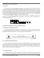
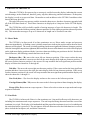
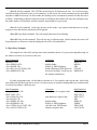
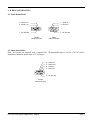
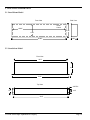
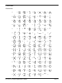
Vorne Industries
GY2200
Serial Input Alphanumeric Display
User's Manual
1445 Industrial Drive • Itasca, IL 60143-1849 • (630) 875 -3600 • Telefax (630) 875-3609 • www.vorne.com
GY2200 Serial Input Alphanumeric Display
Page 2
GY2200 SERIAL INPUT ALPHANUMERIC DISPLAY
Table Of Contents
1.
INTRODUCTION TO THE DISPLAY
1.1
Operation ................................................................................................. 4
2.
SETTING UP THE DISPLAY FOR YOUR APPLICATION
2.1
Changing User Configurable Functions .................................................... 4
2.2
Selecting Special Input/Output Types....................................................... 4
2.3
Selecting Baud Rates................................................................................ 4
2.4
Selecting Protocol Parameters ................................................................. 5
2.5
Selecting Line Terminator ........................................................................ 5
2.6
Addressing ............................................................................................... 5
3.
WRITING TO THE DISPLAY
3.1
Direct Mode ............................................................................................. 6
3.2
Line Mode ................................................................................................ 6
3.3
Escape Mode and Escape Sequences ....................................................... 7
3.4
Data Entry Examples ................................................................................ 8
4.
WIRING INFORMATION
4.1
Panel Mount Model .................................................................................. 9
4.2
Stand Alone Model .................................................................................. 9
5.
MOUNTING INFORMATION
5.1
Panel Mount Model ................................................................................ 10
5.2
Stand Alone Model ................................................................................ 10
6.
APPENDIX
Character Set .......................................................................................... 11
GY2200 Serial Input Alphanumeric Display
Page 3
1. INTRODUCTION TO THE DISPLAY
1.1 Operation
LSD
off on
lf
addrs
00-no
99-all
1 2
off on
cr
par off on
stop
BAUD
RATE
data 7 8
4800
9600
2400
300
1200
1 2 3 4 5 6 7 8 9 10
MSD
The GY2200 is a serial input alphanumeric display. It can accept TTL, RS232, RS422, RS485, or
Current Loop as serial data types (depending on input module implemented) and display information on a field
of 10 characters. Baud rates of 300, 1200, 2400, 4800 and 9600 are DIP switch selectable, as are protocol
parameters of stop bits, data bits and parity. The GY2200 can be set up to work in a line mode (updating
the entire display field after receiving a carriage return, a line feed, or a carriage return / line feed combination),
or in a direct mode (updating the display with every new character received). Up to 98 units can be individually
addressed on a common data bus through use of internal DIP switches.
The GY2200 is capable of scrolling a text message of up to 60 characters in length. Any part of a text
message can be flashed, and a flashed message can be scrolled. The flash rate, scroll rate, and brightness level
can be controlled via software.
O 1 2 3 4 5 6 7 8 9 10
N
2 3
4
1
5
0
9 8 7 6
2 3
4
1
5
0
9 8 7 6
2. SETTING UP THE DISPLAY FOR YOUR APPLICATION
2.1 Changing User Configurable Functions
All user configurable functions (Baud rate, protocol parameters, line terminator, addressing modes) are
located on the main logic board of the GY2200. To access the main logic board, remove the four #4 screws
which hold the back access plate to the rest of the enclosure (see warning below).
Wa rning - S hock H a za rd
D isconnect pow er to the displa y prior to removing the ba ck a ccess pla te.
D o not rea pply pow er until the ba ck pla te ha s been reinsta lled.
!
2.2 Selecting Special Input/Output Types
Any one of the five available serial types (TTL, RS232, RS422, RS485 or Current Loop) can be active
at one time. Exchanging input/output boards selects the serial input and output type. Any input type can be
ordered with a unit, as well as separately. Serial output (retransmission) is available as RS232, RS485, or
RS422. The input board is mounted to the logic board. In order to access the input board, it is necessary to
remove the back access plate (see warning above).
2.3 Selecting Baud Rates
The Baud rate is user selectable as either 300, 1200, 2400, 4800 or 9600, respectively, via the first 5
positions of a PC mounted, 10 position, in-line DIP switch. Only one switch of the first five should be in the
GY2200 Serial Input Alphanumeric Display
Page 4
on position. This switch will determine the Baud rate.
2.4 Selecting Protocol Parameters
Positions 6-8 of the PC mounted, 10 position, in-line DIP switch select protocol parameters. Position 6
selects the number of data bits (7 bits when off, 8 bits when on). Position 7 selects parity, and is selectable
between none (switch off- no parity bit allowed) and mark (switch on- parity bit received and ignored).
Position 8 selects the number of stop bits after the data word (1 stop bit when off, 2 stop bits when on).
2.5 Selecting Line Terminator
The GY2200 can be configured for direct mode or line mode depending upon how the line terminator
switches are set. Positions 9 & 10 of the PC mounted, 10 position, in-line DIP switch select the line terminator.
The line terminator determines when the GY2200 will update its display. If no line terminator is chosen (both
9 and 10 off), the unit will be configured for direct mode. All characters transmitted to a unit in direct mode
will be processed immediately.
If one or both of the line terminators (<CR> and <LF>) have been chosen, the display will update in
line mode. The data to be displayed should be transmitted first, followed by the line terminator. The display
is updated after the line terminator is received. To select carriage return (ASCII 0DH) as the line terminator,
switch position 9 should be on. To select line feed (ASCII 0AH) as the line terminator, switch position 10
should be on. To select carriage return / line feed as the line terminator (ASCII 0DH 0AH), both switch
positions 9 and 10 should be on.
When both a carriage return and a line feed are specified as line terminators, the order in which they are
transmitted is irrelevant, but the characters must be consecutive. If the line terminator pair is separated by any
other character, the first line terminator character will be ignored.
2.6 Addressing
Addressing allows multiple GY2200 units to be individually accessed on a common data bus. A set of
two PC mounted, 10 position, rotary DIP switches determine the addressing mode. If addressing is not
required, the two address switches should be set to 00.
The GY2200 display can be assigned a two digit address. Each GY2200 display that is to be used in
the address mode must have an address between 01 and 98 set on the two PC mounted, rotary DIP switches.
When this condition is met, the GY2200 will display incoming data only when the transmitted address matches
the address set internally in the unit. If it is desired to have a particular display show every set of data
transmitted, regardless of the transmitted address, set the two address switches to 99. Conversely, if it is
desired to have every display show a set of data transmitted, regardless of the display address, transmit an
address of 99 preceding the data.
GY2200 Serial Input Alphanumeric Display
Page 5
3. WRITING TO THE DISPLAY
When the GY2200 is first powered up, a message is scrolled across the display, indicating the current
switch settings, such as Baud rate, data bits, parity, stop bits, addressing, and line terminators. At that point,
the display is ready to accept serial data. Remember to send an address to the GY2200 if an address other
than 00 has been specified.
The end of this power-up message, and the test mode character set, has three characters appended with
all of the LED dots turned on. These three characters are displayed as a lamp test for the GY2200 display
field.
The GY2200 has a 60 byte buffer capable of storing messages of up to 60 characters in length. The
buffer is filled in from the left most position (character position 01) to the right most position (character position
60). This means that messages of up to 60 characters in length can be scrolled at one time.
3.1 Direct Mode
The GY2200 is in direct mode if no line terminators are set. Direct mode accepts and processes
characters immediately. A flashing cursor is initially turned on to indicate the position where the next literal
character will be placed. The cursor is initially positioned at the most significant (leftmost) character position.
After the least significant position (rightmost) has been filled, the next valid character received will be displayed
on the right most display position with the 9 previous characters shifting one position to the left. Besides the
literal characters, the following control characters can be used:
Backspace (08H - ^H): moves the cursor left one character position. If the cursor reaches the most
significant position and there is more text to the left, the entire display shifts right one character position. If
the cursor reaches character position 1, the cursor will wrap around to the least significant position and the
display will show the characters 51 through 60.
Tab (09H - ^I): moves the cursor right one character position. If the cursor reaches the least significant
position and there is more text to the right, the entire display shifts left one character position. If the cursor
reaches character position 60, the cursor will wrap around to the most significant position and the display will
show the characters 1 through 10.
Line Feed (0AH - ^J): clears the display and moves the cursor to the left most position.
Carriage Return (0DH - ^M): moves the cursor to the left most position without changing the display.
Escape (1BH - Esc): starts an escape sequence. Please refer to the section on escape mode and escape
sequences for details.
3.2 Line Mode
The GY2200 is in line mode if there is a line terminator set. Line mode buffers up to 60 characters, not
including line terminators and escape sequences. The unit keeps buffering characters until the correct line
terminator is received. The display is left undisturbed until the proper line terminator is received, at which point
the entire data buffer is processed. The unit ignores all literal characters after the 60th character is received
(these include the backspace, tab, and delete characters).
GY2200 Serial Input Alphanumeric Display
Page 6
3.3 Escape Mode and Escape Sequences
The purpose of the escape mode is to allow commands (such as addressing, flashing, scrolling, etc.) to
be sent to the GY2200 display. Escape mode is entered by sending the escape character (ASCII 1BH).
Escape mode is active in both direct mode and line mode, though some of the functionality varies. The data
stream following an escape character is interpreted as an escape sequence. The characters are not recognized
as literal or control characters. The exact number of command data characters required depends upon the
particular escape command used.
<Esc> # #: specifies a unit address. A unit starts to respond to the serial data stream once a valid
address is recognized through this escape sequence. The unit keeps recognizing characters until a different
address is specified by another escape sequence. Since the address 00 is invalid, sending the escape sequence
<Esc>00 forces all units to stop processing the serial data until a valid address is recognized. The escape
sequence <Esc>99 is a universal address and forces all units to recognize the following data stream.
The following escape sequences are recognized only by units that have been addressed:
<Esc>@: Display reset. Sending this escape sequence causes the GY2200 display to perform a
software reset.
<Esc>Achar: All command. Will fill the entire display with the character <char>. This command can
also be used to clear the display by sending a blank for <char>.
<Esc>B#: Brightness level command. # is in the range from 1 (dimmest) to 9 (brightest). By default,
the display is set to the brightest level.
<Esc>C##: Cursor positioning command. ## is in the range from 01 to 60. In direct mode, this
command will cause the cursor to immediately jump to the absolute location specified. The escape sequence
<Esc>C00 stops the cursor from flashing, and <Esc>C99 starts the cursor flashing.
In line mode, this command can only be given before any literal characters have been transmitted to the
display. This allows parts of the display to be changed without rewriting the entire display.
<Esc>F: Flash delimiter. The flash command allows parts of a message or an entire message to flash.
To use the flash command, surround any parts of a message that is to flash with the flash delimiter. If it is
desired to flash the entire message, preceed the message with the flash delimiter. In direct mode, another flash
delimiter would be needed to prevent any further messages from flashing. In line mode, a matching flash
delimiter is automatically appended following a line terminator if none was specified.
<Esc>N##: Number of blanks put in-between scrolled messages. ## can range from 00 to 99. By
default, the number of blanks is set to the display width of 10 characters.
<Esc>RF#: Rate of flash command. # can range from 1 (slowest) to 9 (fastest). By default, the flash
rate is set to 6.
<Esc>RS#: Rate of scroll command. # can range from 1 (slowest) to 9 (fastest). By default, the scroll
rate is set to 6.
GY2200 Serial Input Alphanumeric Display
Page 7
<Esc>S: Scroll command. The GY2200 can scroll up to 60 characters at once. To scroll a message,
send the message followed by the scroll command. In line mode, the scroll command can be embedded
anywhere within the message. In direct mode, the flashing cursor is temporarily turned off while the text is
scrolling. Transmitting a character when a message is scrolling in direct mode will cause the scrolling to stop,
the entire display to be blanked, and the character transmitted to be processed.
<Esc>U: Undo command. Undo only operates in line mode. Any unprocessed characters or escape
sequences since the last line terminator will be ignored.
<Esc>XF: Stop flash command. This will stop all characters from flashing.
<Esc>XS: Stop scroll command. This will stop any scrolled message. In direct mode, the cursor will
be positioned over character 1 and the displayed text will be left undisturbed.
3.4 Data Entry Examples
All examples are with a CR (carriage return) line terminator chosen. If you are not using addressing, set
the address switches to 00 and reset the unit.
Data Transmitted
DISPLAY<CR>
<Esc>FHELLO<CR>
<Esc>B1LED<CR>
<Esc>RF1<Esc>FGY2200<CR>
<Esc>SMESSAGE<CR>
Comments
display flashes
display @ MIN brightness
display flashing @ MIN flash rate
the word “message” scrolls across
the display continuously
Data Displayed
DISPLAY
HELLO
LED
GY2200
MESSAGE
For units using addressing: set the address switches to 01, for example, and reset the unit. Notice that
once addressed data has been sent to a unit, it is not necessary to continue sending addresses with data until
it is desired to address a different unit.
Data Transmitted
<Esc>01GY2200<CR>
NEW TEXT<CR>
<Esc>07HELLO<CR>
<Esc>01LED<CR>
<Esc>FDISPLAY<CR>
<Esc>B1SERIAL<CR>
<Esc>FTHIS<Esc>F UNIT<CR>
<Esc>99ALL UNITS<CR>
GY2200 Serial Input Alphanumeric Display
Comments
unit address 01 recognizes data
unit address 01 ignores data
display flashes
display @ MIN brightness
only the word THIS flashes
all units recognize data
Data Displayed
GY2200
NEW TEXT
NEW TEXT
LED
DISPLAY
SERIAL
THIS UNIT
ALL UNITS
Page 8
4. WIRING INFORMATION
4.1 Panel Mount Model
1 - Serial out +
2 - Serial out -
1 - Serial in +
2 - Serial in -
7 - DC Ground
7 - DC Ground
Female
DB-9 Connector
Male
DB-9 Connector
4.2 Stand Alone Model
Note: All models are supplied with a standard IEC 320 detatchable power cord for 120 VAC power.
Maximum continuous power draw is 15 Volt/Amps.
4 - Serial out 3 - Serial out +
2 - Serial in 1 - Serial in +
7 - DC Ground
Female
DB-9 Connector
GY2200 Serial Input Alphanumeric Display
Page 9
5. MOUNTING INFORMATION
5.1 Panel Mount Model
Front View
Side View
Panel
Cutout
19.90"
5.35"
4.40"
20.88"
2.50"
5.2 Stand Alone Model
Front View
19.9"
4.4"
21.5"
Top View
3/8" DIA
1.84"
2.4"
20.9"
GY2200 Serial Input Alphanumeric Display
Page 10
6. APPENDIX
Character Set
00h
01 h
02 h
03 h
04 h
05 h
06 h
07 h
08 h
09 h
0Ah
0B h
0C h
0Dh
0Eh
0F h
1 0h
11h
1 2h
13h
1 4h
15h
1 6h
17h
1 8h
1 9h
1 Ah
1 Bh
1 Ch
1 Dh
1 Eh
1 Fh
2 0h
21 h
22h
23 h
24h
25 h
26h
27 h
28h
29h
2 Ah
2Bh
2Ch
2 Dh
2 Eh
2Fh
3 0h
31h
3 2h
33h
3 4h
35h
36h
37h
3 8h
39h
3 Ah
3 Bh
3 Ch
3 Dh
3 Eh
3 Fh
4 0h
41 h
42h
43 h
44h
45 h
46h
47 h
48h
49h
4 Ah
4Bh
4Ch
4 Dh
4 Eh
4Fh
5 0h
51h
5 2h
53h
5 4h
55h
56h
57h
5 8h
59h
5 Ah
5 Bh
5 Ch
5 Dh
5 Eh
5 Fh
6 0h
61 h
62h
63h
64h
65h
66h
67 h
68h
69h
6 Ah
6Bh
6Ch
6 Dh
6 Eh
6Fh
7 0h
71h
7 2h
73h
7 4h
75h
7 6h
77h
7 8h
7 9h
7 Ah
7 Bh
7 Ch
7 Dh
7 Eh
7 Fh
GY2200 Serial Input Alphanumeric Display
Page 11
Vor ne Industries
1445 Industrial Drive
Itasca, IL 60143-1849
Tel: (630) 875-3600
Fax: (630) 875-3609
www.vorne.com
Incor
por
a ted
Incorpor
pora
P0039R04