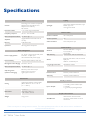
1
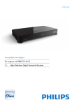
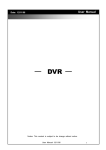
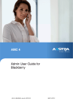
DEVA The revolutionary multimedia unit: energetically self-sufficient, zero installation costs, solar power ready User GUIDE July 2014 © 2014 Powersoft DO000147 Rev. 1 Keep This Manual For Future Reference Table of Contents 14 Start-up 14 1 Unpacking & checking 4 2 Disposal of the packing material 4 3 Package content 4 15 Shut down 15 4 Welcome 5 16 USB MP3 playback 15 5 DEVA in a glance 5 17 Networking 16 6 Dashboard 6 7 Actions and Players 7.1 Actions 7.2 Players 8 Commanders and Triggers 10 10 10 11 14.1 DEVA start-up without external power supply 17.1 DEVA in a wireless LAN 17.1.1 Mesh network 17.2 DEVA in a wired LAN 18 Initialization 18.1 Initialization in a wireless LAN 18.2 Initialization in a wired LAN 14 16 16 17 17 17 18 8.1 Commanders 11 8.1.1 Live execution 8.1.2 Time schedule 8.1.3 Events 8.1.4 USB key 11 11 11 11 Setting DEVA 19 19 Setting users permissions 19 11 20 DEVA general settings 20 9 Warning beeps 12 21 Setting Zones 21 10 Dashboard LEDs 12 22 Audio library and playlists 22 11 Front RGB LED 12 8.2 Triggers Getting Started 13 12 Battery assembly 13 13 SIM card assembly 14 2 | DEVA | User Guide 22.1 Setting a playlist 22 23 Predefined messages 23 24 Setting time schedule 24 25 Setting Events 25 powersoft_DEVA_uguide_v2.7 DEVA User Guide 26 Live execution 25 27 Advanced network settings 26 27.1 Setting PDD network parameters 27.1.1 Setting PDD’s static IP 27.2 Setting DEVA network parameters 27.3 Configuring a WiFi mesh network 27.3.1 Setting DEVA as Gateway 27.3.2 Setting DEVA as Node 26 26 27 28 28 28 27.4 Revert to DEVA default network settings29 27.4.1 Wi-Fi intrastructure mode 27.4.2 Wi-Fi access point mode 29 29 Reset and reboot 31 28 DEVA reboot 31 29 DEVA reset 29.1 Soft-reset 29.2 Hard-reset Software update 32.1 Needed tools 32.2 Pole and wall mounting kits 32.3 Tripod mounting clamp 35 35 36 33 Solar panel 36 33.1 Plugging the solar panel 36 34 DEVA passive 38 PDD and DSM 39 A Powersoft DEVA Director – PDD39 A.1 Minimum system requirements for PDD 39 B DEVA System Manager – DSM 39 31 Regulations and warnings 40 31 32 C Warnings about using batteries 40 D Warnings about Wi-Fi 40 Specifications 42 33 30 DEVA software update procedure33 31 Update the DEVA System Manager34 Accessories35 32 Mounting kits 35 DEVA | 3 1 Unpacking & checking Your Powersoft product was completely tested and inspected before leaving the factory. Carefully inspect the shipping package before opening it, and then immediately inspect your new product. If you find any damage notify the shipping company immediately. 2 Disposal of the packing material The transport and protective packing has been selected from materials which are environmentally friendly for disposal and can normally be recycled. Rather than just throwing these materials away, please ensure they are offered for recycling. 4 | DEVA | User Guide 3 Package content The main package contains: ff DEVA ff Connectors kit ff Power supply plug: Phoenix MCVW-1.5/ 2-STF-3.81 ff Loudspeaker plug: Phoenix 1803578 MC 1,5/ 2-ST-3,81 ff RS-485 plug: Phoenix 1817042 1840405 MC 1,5/ 6-ST-3,5 ff Manual Optional: ff Pole and wall mounting kits ff Mounting clamp for stand ff Solar panel ff DEVA Passive ff ANSMANN APS2250H DC power supply and adapters DEVA User Guide 4 Welcome 5 DEVA in a glance Congratulations on your purchase of the Powersoft DEVA. DEVA is a lightweight and compact multifunctional device that implements bi-directional wireless communication, audio messaging and video capturing. DEVA is capable to perform tasks and react to certain events on the basis of a scheduled program and an event list. The interaction with the environment triggers a set of actions spanning from sound playback to taking pictures. In systems with more than one DEVA, scheduled actions – such as playing audio files – are synchronized by means of Once configured, DEVA is a self-sufficient device the DEVA System Manager, the control pannel that equipped with sensors – microphone, presence provides full management of DEVA, installed into detector, temperature and pressure probes – and the Powersoft DEVA Director – PDD. accessories (e.g. LED light, camera, etc.) that make it capable to interact with the environment through The DEVA System Manager allows you to stream the built in loudspeaker and audio/video capturing live announcements and audio files to all selected DEVA as well as set: feature. DEVA has been designed to be independent from any existing infrastructure, without the need for ff time schedule for actions: wiring and with virtually zero installation costs. DEVA ff Light – switch the light on or off. uses green technologies: its highly efficient design ff Play message – play a file in the default limits power consumption allowing uninterrupted audio files list. use powered by the internal rechargeable battery; ff Play from Audio library – play a file from a latest generation solar panel can quickly recharge the audio library. the battery even in low light conditions. ff Play playlist – execute a playlist of audio files. DEVA's enclosure is weather-resistant IP65, ff Take Photo – shoot a single ambient photo an ideal solution for outdoor applications from or choose to shoot a number of pictures background music to paging, in combination with delayed by the selected time. video and/or audio surveillance. Refer to Chapter “7 Actions and Players” for DEVA provides bi-directional messaging and detailed info. ambient control; DEVA allows configuration and monitoring via WiFi as well as wired Ethernet ff action triggers (events): connections to tablets, pc and mobile phones. ff Presence sensor Remote control is available via GSM/GPRS/UMTS. ff Battery charge ff Network connectivity DEVA is a self-sufficient fully configurable ff Mechanical shocks networking unit that can be installed anywhere! Refer to Chapter “8 Commanders and Triggers” for detailed info. DEVA | 5 When triggering events take place, DEVA can execute one or more of the following actions: ff Light ff Play message ff Record with the built in microphone ff Take Photo ff Notify – send an sms to a registered user. 6 Dashboard The DEVA dashboard is located under the rear panel of the DEVA; it allows the user to access the main connections (i.e. solar panel, ethernet, etc), the power switch and other features (refer to the next chapters for further details). Refer to FIGURE 1 to locate the following features on the dashboard. Refer to Chapter “8 Commanders and Triggers” for detailed info. 1. Factory Default Setting push-button Chapter “29 DEVA reset” 2. ON/OFF push-button Chapter “14 Start-up” 3. Volume +/– push-button Chapter “16 USB MP3 playback” 4. Seek track push-button Chapter “16 USB MP3 playback” 5. Loudspeaker plug Chapter “34 DEVA passive” 6. RS-485 and switch plug 7. USB connector Chapter “16 USB MP3 playback” 8. 5.5 mm coaxial power supply plug (16 VDC, 1 Amax) 9. Rear status LEDs – Red, Yellow, Green Chapter “10 Dashboard LEDs” 10.Network activity LED 11. Ethernet port 12.SIM bay Chapter “13 SIM card assembly” 13.Wi-Fi default setting selector Chapter “29 DEVA reset” 14.Cable fastener 15. Phoenix MC 1,5/ 2-ST-3,81 solar panel connector Chapter “33 Solar panel” 16.Testing connectors for servicing 6 | DEVA | User Guide 1 2 3 4 5 6 7 8 9 10 11 12 13 16 15 14 FIGURE 1: DEVA dashboard. DEVA | 7 300 mm 220 mm A B 440 mm 435 mm C D E F 163 mm G FIGURE 2: Mechanical drawing 8 | DEVA | User Guide A. B. C. D. E. F. G. Built-in loudspeaker LED Light Front status RGB LED Built-in microphone Built-in camera Presence IR sensor Bracket Page intentionally left blank 9 7 Actions and Players 7.1 Actions The player with the lower priority plays in background (i.e. lower in volume) when a high priority player starts playing. Depending on the version, DEVA performs a set of defined actions: Playlist ff Play audio ff Switch the light ff Take photo ff Record audio ff Notify with a message (sms/email) Play a file Time Play a file Volume 100% Volume 30% Playlist 7.2 Players DEVA provides four audio players that manage respectively: 1. live stream of audio 2. playback of single audio file 3. playback FM radio 4. playlist of audio files FIGURE 3: The playback of a single audio file has the priority on a playlist: the volume of the playlist is lowered to the 30% and the playback does not stop. Playlist Play a file Streaming Time Volume 100% Streaming Volume 100% The four players can be active at the same time, but only two of them will play simultaneously, according to their priority: Volume 30% Play a file Volume 100% Volume 30% live stream > single file > FM radio > playlist high priority > Playlist MUTE low priority FIGURE 4: DEVA can reproduce up to two fluxes of audio simultaneously: in this example the playback of The four audio players are layered on the basis of the playlist is muted whilst playing the audiofile and the live streaming. the playback priority: ff the playback of a live streaming (either an audio file or from the microphone) has the priority on the playback of an audio file from the library; NOTE: The default behaviour can be overridden by changing the volume level during the playback. ff the playback of a single audio file has the priority Each player provides independent volume control. The playback volume of each player is a fracion on the playback of the FM radio; (expressed in percentage) of the master volume. ff the playback of an FM radio has the priority on the playback of a playlist. 10 | DEVA | User Guide 8 Commanders and Triggers 8.1.4 USB key DEVA can start playing audio files from any USB 8.1 Commanders storage device, such as a USB key, plugged into the DEVA receives commands to perform actions. USB port on the DEVA dashboard. Refer to Chapter “16 USB MP3 playback”. Commanders access a subset of actions. 8.2 Triggers 8.1.1 Live execution Triggers are conditions that activate functions of The DEVA System Manager provides direct access the DEVA. The tool Events uses triggers. to all actions on DEVA; through the DSM you can: Events/conditions that trigger DEVA actions can ff Play audio • stream an announcement/audio file be chosen among: • play a predefined message • execute a playlist • play an FM radio ff Switch the light ff Mute audio playback ff Take a photo ff the signal from the presence sensor ff internal battery voltage (threshold: 11.8V) ff Wi-Fi and LAN network connectivity ff mechanical shocks ff external switch Refer to Chapter “26 Live execution”. When a triggering condition takes place, DEVA perform the programmed action. 8.1.2 Time schedule Triggers are filtered by time: you can set the time The DSM provides a tool to set the executions of actions on a time schedule. Available actions are: interval during which the triggering conditions are taken into account. ff Play audio • play a predefined message • execute a playlist • playpack a single audio file • playback an FM radio ff Switch the light ff Record audio ff Take photo Refer to Chapter “24 Setting time schedule”. 8.1.3 Events Ambient events can be exploited to activate some actions: ff Play audio • play a default message ff Switch the light ff Record audio ff Take photo/video ff Notify with an sms Refer to Chapter “25 Setting Events”. DEVA | 11 9 Warning beeps 11 Front RGB LED Many system functionalities are warned The front LED is positioned in the center of the by acoustic signals (beep)s. In the following light LED (ref. FIGURE 2). The activity of the front table a dot � represents a short beep, LED is triggered by the presence sensor: the LED lights just when the sensor reveals the presence of a dash – represents a long beep. people in front of the DEVA. system status beeps combination STARTING SOFT RESET � — ��� �� STARTING HARD RESET �– BUTTON PRESSED SYSTEM BOOTING REBOOT The color code refers to the battery state; the lightening state refers to the LAN (both wired and wireless) connectivity status. connectivity status 10 Dashboard LEDs RED BLUE GREEN LAN CONNECTIVITY PRESENT SOLID ON SOLID ON SOLID ON NO LAN CONNECTIVITY BLINKING BLINKING BLINKING The status LEDs in the dashboard (ref. FIGURE 5) provide the following information: battery status battery status RED CHARGING SOLID ON FULL CHARGE SLOW BLINKING IDLE DISCONTINUOUS BLINKING NO BATTERY OFF Color BATTERY CHARGE AT WARNING LEVEL (11.8V) RED NO CHARGING BLUE CHARGING GREEN During system update the LED color turns purple and blinks until the end of the process. system status YELLOW GREEN NO POWER SUPPLY OFF OFF BOOTING OFF BLINKING SYSTEM ON OFF SOLID ON SYSTEM OFF CAUSED BY USER SHUTDOWN SLOW BLINKING OFF SYSTEM OFF CAUSED BY LOW BATTERY CHARGE BLINKING OFF SOLID ON IRREGULAR BLINKING SHUTTING DOWN 12 | DEVA | User Guide PURPLE (blinking) SYSTEM UPDATING System status FIGURE 5: Status LEDs. Battery status Getting Started Before proceeding to the placement of the 12 Battery assembly DEVA on site (ref. Chapter “32 Mounting kits”), we recommend to setup the device by following DEVA comes with a battery pack already located the assembling and initialization procedure “on the into its battery compartment (ref. FIGURE 6). The desk”. battery pack shall be properly connected before The initialization phase can involve the manual operating. setup of the device; once properly initialized and 1. Open the battery compartment. configured, DEVA has been designed to be self- 2. Verify that the battery presents no failures. operating and remotely managed. 3. Plug the battery: The initialization workflow includes: ff connect the red + (positive) faston to the battery’s positive plug (beware the 4 A fuse); 1. battery assembly on the DEVA; ff connect the black – (negative) faston to the 2. SIM assembly; battery’s negative plug. 3. DEVA start-up; 4. Place the battery temperature probe wherever 4. initialization of the connections (networking); into the battery compartment, far from the electric plugs. We suggest to follows the instruction on this 5. Reposition the compartment cover and tightly manual in order to properly setup the DEVA. screw the six hex screws. In order to ensure full operability, Powersoft recommends to fully charge the battery before starting the initialization procedure. Battery compartment Dashboard compartment The battery charge can be achieved by means of either: ff an external power supply capable to deliver 20 VDC and up to 3 Amax (e.g. solar panel, DC power supply unit, etc.) connected to the Phoenix MC 1,5/ 2-ST-3,81 (ref. FIGURE 1 #15); ff a 16 VDC , 1 Amax power supply plugged to the 5.5 mm coaxial plug (ref. FIGURE 1 #8); ff a 48 VDC PoE via the Ethernet connection (ref. FIGURE 1 #11). FIGURE 6: DEVA back view. Getting Started | 13 13 SIM card assembly 14 Start-up DEVA supports GSM and GPRS communication Once the battery has been properly assembled protocols via a standard SIM – Subscriber Identity (ref. Chapter “12 Battery assembly”), the DEVA can Module – card*. Follows these instructions in order be switched on. By default, DEVA starts-up when any external power supply (i.e. solar panel, DC to install the SIM card. power supply unit, PoE) is plugged in. When the DEVA is connected to an external 1. Unlock the SIM by disabling the PIN request at the switch on: this can be mabe easily by power supply, the system starts charging the internal inserting the SIM into a mobile phone and battery: when the power supply delivers more than 12 VDC the DEVA starts-up automatically. disabling the PIN request. In approximatively 90 seconds the operating 2. Access the dashboard compartment and gently system completes the bootstrap procedure and slide and tilt the SIM card tray (ref. FIGURE 7). makes the device ready to work. During the bootstrap you can hear a long beep coming from 3. Insert the SIM card into the slot a reposition the DEVA: the presence of this signal means that the system is booting. the tray. 14.1 DEVA start-up without external power supply SIM card tray FIGURE 7: SIM card tray on dashboard. The GPRS communication features shall be activated and managed through the DEVA System Manager (ref. Chapter “27.2 Setting DEVA network parameters”) In case no power supply is available and DEVA is off, you can switch on the DEVA by means of the ON/OFF button (ref. FIGURE 9). 1. Push on the ON/OFF button and keep it pressed: 2. the green LED switch solid on; 3. still keep the ON/OFF button pressed until the green LED start blinking (5 s approximatively); 4. release the ON/OFF push button: the bootstrap procedure takes place and a long beep is emitted. Be aware that the start-up procedure without power supply will not take place if the battery charge is below 12 VDC . FIGURE 8: System settings: network parameters. * Not included in the package. Ask to your local IT providers. 14 | DEVA | User Guide 15 Shut down 16 USB MP3 playback Usually you don’t need to shut down the DEVA The playback from the USB override any audio for maintenance: the management can be performed playing on the DEVA: in order to start the playback by means of the DEVA System Manager. of the files from a USB device you have to press simultaneously the SEEK+ and SEEK– push button 1. Access the DEVA on site and remove the on the DEVA dashboard. The actual scheduled action does not stop: while dashboard cover on the back of the DEVA (ref. the USB audio content is playing, any scheduled FIGURE 6). playlist runs to the 30% of its preset volume. In order to allow DEVA to reproduce the MP3 files from the USB, the audio files shall be stored in the AudioFiles folder in the root of the USB storage device. DEVA can play only MP3 files, no other file ON/OFF Status formats are allowed. Playback of the audio files is button LEDs looped in alphabetical order. The commands to FIGURE 9: ON/OFF button and manage the playback from USB are located on the status LEDs on dashboard. DEVA dashboard (ref. FIGURE 10): 2. In order to completely shut down the DEVA we suggest to unplug any external power supply (e.g. solar panel). 3. On the DEVA dashboard, identify the On/Off push-button (ref. FIGURE 9): keep pressed the button until the three rear LEDs start blinking. 4. Release the On/Off push-button and wait until all the LEDs switch off (approximatively one minute). The system will emit 2 short beep followed by a long beep to warn you about the shut down in progress PLAY/STOP ff press simultaneously the SEEK+ and SEEK– push button to toggle PLAY and STOP VOLUME ff push once on VOL+ or VOL– button for a 1% volume change accordingly ff push and keep pressed on VOL+ or VOL– button for a 5% volume change per second accordingly TRACK SEEK ff press on the SEEK+ and SEEK– push button to skip track Take care to properly stop the audio file playing from the USB before unplug the USB device! By unplugging the USB device without having properly stopped the playback you may cause the USB stop working until next system reboot. FIGURE 10: Press simultaneously the SEEK+ and SEEK– push button to toggle PLAY and STOP from USB Getting Started | 15 17 Networking DEVA can be set as a stand alone device or integrated into any existing wired, wireless or mixed network. A proper network setup includes: ff Powersoft DEVA Director – PDD. The PDD is a personal computer implementing a custom GNU/Linux based operating system: the PDD provides a client-server environment that allows the user to easily manage the network of DEVA. PDD ACCESS POINT Both the DEVA and the PDD must be connected to the same network; this means that all devices have to be either hosted by the same Wi-Fi access point or wired to the same thernet switch and sharing the same subnet and IP range. 17.1.1 Mesh network DEVA can connect to a mesh network, so that to cooperate in the distribution of data in the network. ff DHCP server (often already implemented into In a mesh network topology, each DEVA is a node routers and acces point). Both the DEVA and that relays data on the network, providing multiple the PDD are set to dynamic IP addressing. connections to other DEVA in the mesh. ff Ethernet switching (often already implemented into routers and acces point) with a proper ROUTER WITH number of ports for wired connectivity; DHCP + switch ff Wi-Fi access point for wireless connectivity; ff One or more DEVA. In the following pictures we suggest some network topologies oriented to a domestic environment, where the router/AP implements both the DHCP server and the Ethernet switch. 17.1 DEVA in a wireless LAN DEVA and the PDD are connected wireless to the access point. Any further client on the wireless network can manage the network of DEVA: in order for the client to manage a DEVA it must to connect to the PDD. 16 | DEVA | User Guide PDD 17.2 DEVA in a wired LAN 18 Initialization Both the DEVA and the PDD must be connected to the switch. The DHCP on board of the router The initialization is performed by means of the assign a unique IP address to each DEVA and PDD in PDD – Powersoft DEVA Director –, by connecting order for them to belong to the same subnet. the DEVA to the local network through a wired or Through the PDD it is possible to manage the wireless connection. network of DEVA, set schedules and events, monitor You may need the following equipment: the performance and launch an announcement on ff Powersoft DEVA Director – PDD; specified DEVA. ff DHCP server or a router with DHCP capability; ff switch with a proper number of ports for wired connections; ff access point – AP – for wireless operating. 18.1 Initialization in a wireless LAN ROUTER WITH DHCP + switch By default DEVA tries to connect to a Wi-Fi network whose SSID is set to POWERSOFT. In order to perform the initialization procedure we recommend to set your AP as follow. PDD 1. Connect the PDD and the AP to the same LAN (wired or wireless): ensure that they share the same IP range. Refer to Chapter “27 Advanced network settings” for more information on how to configure the DEVA network parameters and the PDD in order to match your network environment. 2. Log-in the PDD and launch the browser. 3. Point your browser to the IP address of the access point and enter its control panel. 4. Modify the SSID of the access point to “POWERSOFT” and password “powersoft”. Save and reboot the access point. While rebooting you will loose the connection: after some second, refresh the page on the browser and reconnect to the AP. 5. By default DEVA looks for the POWERSOFT Wi-Fi network. Through the AP control panel you should monitor all connected devices. Getting Started | 17 System Manager: 18.2 Initialization in a wired LAN address-bar write In order to perform the initialization procedure in a wired network environment, all devices have to be connected to a DHCP server (possibly through 7. Log in the DEVA System Manager: the an Ethernet switch) in order to receive unique IP administrator account has the following default addresses within the same subnet. credentials: 1. Connect the PDD and the DHCP server to username: admin the same network: ensure that they share password: admin the same IP range, i.e. the PDD receives its IP address from the local DHCP server. 6. Open the DEVA on the browser http://localhost:8080 2. Connect each DEVA to the same network of your PDD and switch them on (ref. Chapter “14 Start-up”). 3. Now follow the same procedure described in Chapter “18.1 Initialization in a wireless LAN” starting from point 6. FIGURE 11: DEVA system Manager login window. Once logged in, the DEVA System Manager shows the latest saved network configuration: since you are going to initialize your network, no one DEVA is listed. FIGURE 12: DEVA System Manager at first login. 8. Click the button Discovery on the Toolbar: the DEVA System Manager will start seeking and connecting new devices on the network. Now you can start setting DEVA. 18 | DEVA | User Guide Setting DEVA Almost any settings on DEVA are performed by means of the DEVA system Manager – DSM. The audio playback from a USB key and the hard-reset of the system are available just through the DEVA dashboard. The DSM offers a user friendly interface for setting time schedules for actions, event triggers and full access to DEVA features (ref. Chapter “5 DEVA in a glance”). 1. Click on the Settings tab in the main bar. The main window switch to the Settings panel. 2. On the left column, click on Users Management (ref. FIGURE 14). 19 Setting users permissions By assign roles to registered users, it is possible to control what users can do through the DEVA System Manager. Each registered user belongs to just one role. Permissions are global, i.e. they grant access to selected features on all networked DEVA. The DEVA System Manager provides three default roles: ADMIN, USER and GUEST. Only the adminstrators can register new accounts and assign roles to users. Refer to TABLE 1 for an overview on user roles and permissions. In order to register new users and set roles: 1 FIGURE 13: Discover connected DEVA and start settings. 2 FIGURE 14: Set users account. 3. Add new account or manage registered users by inserting: ff Login name ff Login password ff Real name ff Role 4. Save by clicking on the Update button (ref. FIGURE 15) 3 4 FIGURE 15: Add new user. Setting DEVA | 19 20 DEVA general settings User role Functions ADMIN USER GUEST Zones management Audio Library management Playlists management Live volume management Live light management Events management Schedulings management System settings/ configurations System and Alarms monitoring Live audio playing (file/ playlist/stream/fm radio) Audio Mute DEVA Diagnosis Take photos Delete photos Take audio recordings Delete audio recordings Run DEVA auto-test A. Click on the Settings tab in the main bar. The main window switch to the Settings panel (ref. FIGURE 16). B. On the left column, click on System settings (ref. FIGURE 17). A FIGURE 16: Discove connected DEVA and start settings. B FIGURE 17: Click on System settings. TABLE 1: User roles amd permissions. C FIGURE 18: Select one DEVA. 20 | DEVA | User Guide D 1 2 FIGURE 19: Edit DEVA general settings. C. Select the DEVA you want to edit (ref. FIGURE 18). A new panel appear providing you information on the device. D. Click on the Edit button in order to start editing the DEVA general settings (ref. FIGURE 19): ff DEVA nickname. ff Phone number of the SIM Card, if present. ff Not Synchronized audio playback, in case of busy or not reliable network connection. ff Auxiliary amplifier, in case a passive loudspeaker is connected to the audio out plug (ref. FIGURE 1 #5). FIGURE 20: Zone management. 2. Add a new Zone by clicking on the Add button in the toolbar. Two panels appear (ref. FIGURE 21): ff the left hand panel lists all available DEVA, i.e. the ones that don’t belong to a Zone; ff the right hand panel lists the DEVA assigned to the present Zone. 4 3 5. Save the new configuration. 21 Setting Zones A Zone is a group of DEVA sharing the same configuration. Working with Zones is easy as working with single DEVA and allows to configure multiple devices at the same time. Once a DEVA is assigned to a Zone, time scheduled actions and event triggers have to be managed by means of the Zone panel on the DEVA System Manager. FIGURE 21: Assign DEVA to the Zone. 3. Give a significative name to the Zone and drag selected DEVA from the left hand panel to the right hand panel. 4. Save the configuration of the Zone. 1. Access the Zone panel by clicking on the Zone tab in the main bar of the DSM (ref. FIGURE 20). Setting DEVA | 21 22 Audio library and playlists In order to set one or more playlists, you have to fill the Audio library of the DSM. 1 2 FIGURE 23: Playlist panel. FIGURE 22: Audio library. 22.1 Setting a playlist A playlist is a list of selected audio files chosen among the ones into the Library of the DSM. The playback of a playlist is one of the main Actions performed by DEVA: playlists are available for single DEVA and Zones in time scheduling, events and live executions. 1. Click the Playlist tab in the main bar: the main window will show you all available playlists (ref. FIGURE 23). 2. Click on the Add button; a new window appears: ff the left hand panel lists all available audio file from the Library; ff the right hand panel lists the audio file assigned to the present playlist. 3. Give a significative name to the playlist and drag audio files from the left hand panel to the right hand panel. 4. Save the playlist. 22 | DEVA | User Guide 3 4 FIGURE 24: Drag sudio files into the playlist. 23 Predefined messages A. Double click on a raw: a dialog window will open (ref. FIGURE 26). Each DEVA can store up to ten predefined audio files outside the audio library. B. Select an audio file from the audio library. A D FIGURE 25: Predefined Messages. FIGURE 27: Edited messages not yet synchronized. These files are common to all the DEVA in the C. Click on the Save button. network and can be live played as instantaneous announces, as well as scheduled or triggered by D. Click on the Save button in the Settings panel in selected events. order to make the new configuration effective The predefined messages can be managed (ref. FIGURE 27). through the Settings panel in the DEVA System Manager (ref. FIGURE 25). The DSM highlight the changes in the predefined The panel displays ten raws identified by the labels: messages with a red triangle located top-right of the filename (ref. FIGURE 27). ff Standard 1 ff Welcome All connected DEVA must be synchronized in ff Standard 2 ff Goodbye order to share the new configuration. ff Standard 3 ff Alarm 1 ff File 1 ff Alarm 2 E. Click on the System tab: a red check-mark on ff File 2 ff Alarm 3 the Settings updated column warn you about the need to synchronize the connected DEVA. Label can not be edited, but you can customize the audio files associated to the labels. F. Select all the DEVA and click on the Sync button. B F C E FIGURE 26: Edit predefined message. FIGURE 28: Synchronize connected DEVA. Setting DEVA | 23 24 Setting time schedule If you want to set a schedule for a Zone, click on the Zone tab in the main bar and start editing the You can schedule actions for single DEVA and zone (ref. FIGURE 31). Zones. The following actions can be scheduled: ff Play audio • play a predefined message • execute a playlist • playpack a single audio file • playback an FM radio ff Switch the light ff Record audio ff Take photo FIGURE 31: Edit a Zone. Both in the DEVA control panel and in the Zone control panel click on the Scheduling button in order to set a time schedule. In the Scheduling panel: 1. Insert a significative name for the schedule; FIGURE 29: System panel. In order to set a schedules for a single DEVA, double click a DEVA in the System panel (ref. FIGURE 29): the DEVA control panel window appears allowing you to manage the device. If the DEVA belongs to a Zone, it inherits the Zone’s schedules: it is not possible to configure a custom schedule for it (ref. FIGURE 30). FIGURE 30: It is not possible to set a custom time schedule because the DEVA belongs to a Zone. 24 | DEVA | User Guide 2. Enable or disable the present schedule: this feature allows you to configure a schedule and let it in stand-by or temporary disabled, even if properly scheduled. 3. Select a starting time and possibly its recurring execution. 4. Select the type of action you want to schedule: the input parameters change regarding to the type of selected action. FIGURE 32: Schedule settings. 25 Setting Events You can set triggering events for single DEVA and Zones. The following actions can be triggered: ff Play audio • play a default message ff Switch the light ff Record audio ff Take photo/video ff Notify with an sms 3. Select a time interval during which an event may trigger an action (optional). 4. Select one or more action triggers among: ff Presence sensor ff Battery charge ff Network connectivity ff Mechanical shocks 5. Select the actions you want to trigger. In order to set an event for a single DEVA, double click a DEVA in the System panel (ref. FIGURE 29): the DEVA control panel window appears allowing 26 Live execution you to manage the device. If the DEVA belongs to a Zone, it inherits the Through the System panel of the DSM you can Zone’s events: it is not possible to configure a execute main actions on selected DEVA: custom events for it. ff Switch the light If you want to set an event for a Zone, click on ff Mute the playback the Zone tab in the main bar and start editing the ff Play audio • stream an announcement/audio file zone (ref. FIGURE 31). • play a predefined message • execute a playlist • play an FM radio ff Set the master volume FIGURE 34: Audio&Light panel. The Audio&Light panel (ref. FIGURE 34) allows you live stream an announcement as well as playback 1. Insert a significative name for the event; audio from the library, FM radios or predefined messages. 2. Enable or disable the present event: this The playback volume of any scheduled, triggered or feature allows you to configure an event and live executed audio is a percentage of the master let it in stand-by or temporary disabled. volume configured in the Audio&Light panel. FIGURE 33: Event settings. Setting DEVA | 25 27 Advanced network settings You can manage your network directly from the PDD or through any external client (e.g. a laptop or an iPad) connected to the network of DEVA since the PDD implements a web server providing remote access to the DEVA System Manager. In order to remotely manage the DEVA you need to connect the client to the PDD: as well as you connect to a website on internet through a web client, you need to know the PDD IP address. The IP address of the PDD can be discovered by means of the Network Manager installed on the operating system. 27.1 Setting PDD network parameters At the end of the initialization procedure the DEVA System Manager has discovered the DEVA within the network. By means of the Dynamic Host Configuration Protocol – DHCP –, each DEVA and the PDD own a unique dynamic IP address: this configuration allows an easy network initialization, since minimizes configuration errors and IP address conflicts. Static IP addressing can be restricted to a subset of devices: you can mix static and dynamic clients on the same network as long as you avoid using static IP addresses within the numeric range where the router/DHCP-server is likely to issue its addresses. Refer to your router/DHCP server user manual for dynamic addressing configuration. FIGURE 35: Edit Eth0 properties. 2. The Network Connections windows opens: into the Wired tab select Eth0 and press on the Edit button (ref. FIGURE 35). 3. A new dialog window will appear where you can set the main parameters of the wired connection: select the IPv4 tab in order to set a static IP address for the PDD wired connection. 27.1.1 Setting PDD’s static IP In order to set a static IP address on your PDD you have to deal with the network manager provided by the GNU/Linux operating system. 1. Press on the network icon on the top panel and select Edit Connections... on the pop-up menu. 26 | DEVA | User Guide FIGURE 36: Select IPv4 manual configuration and set static IP address. 4. Select Manual on the addressing Method dropdown menu. 5. Manually insert: ff IP address: within the router/DHCP-server IP subnet (e.g. 192.168.10.10) ff Netmask (e.g. 255.255.255.0) ff Gateway: same as the IP address (e.g. 192.168.10.10) Be aware to select a static IP address within the router/DHCP-server IP subnet, otherwise you could loose the link with the DEVA connected to the PDD network. 27.2 Setting DEVA network parameters 1. Click on the Settings tab in the main bar. The main window switch to the Settings panel 3 FIGURE 39: Select one DEVA. 2. On the left column, click on System settings 3. Select the DEVA you want to edit. A new panel appear providing you information on the device 4. Click on the Network button. Now you can view the network parameters of the DEVA as well as the Wi-Fi and GPRS configuration. 5. Click on the Edit button to enter the edit mode. 4 1 FIGURE 37: System panel. 5 FIGURE 40: Edit network settings. 2 FIGURE 38: Click on System settings. FIGURE 41: Network and GPRS parameters. Setting DEVA | 27 27.3 Configuring a WiFi mesh network You can configure the DEVA to establish a WiFi mesh network. One of the DEVA in the mesh acts as gateway, i.e. it routes data between networks, and is networked to the same subnet to which the PDD belongs; all other DEVA in the mesh are WiFi nodes. ROUTER WITH DHCP + switch PDD DEVA Node 27.3.1 Setting DEVA as Gateway The DEVA gateway establish the WiFi mesh network and allows the PDD to connect to the mesh. The DEVA gateway shall be connected to the wired LAN to which the PDD belongs. DEVA Gateway DEVA Node 1 DEVA 2 Node FIGURE 42: Setting DEVA as Repeater Gateway. In order for the nodes to recognize the mesh, the WiFi network SSID must be set. 1. In the WiFi: configured parameters panel, click on the Enable check-box in order to allows editing. 2. Click on the Mode dropdown list and select Repeater Gateway. 3. Set the SSID of the WiFi mesh network. 27.3.2 Setting DEVA as Node A. In the WiFi: configured parameters panel, click on the Enable check-box in order to allows editing. B. Click on the Mode dropdown list and select Repeater Node. C. Insert the SSID of the WiFi mesh network. D. Set how to manage the IP addressing (DHCP or static). A 3 FIGURE 43: Setting the SSID. 28 | DEVA | User Guide B C FIGURE 44: Setting DEVA as Repeater Node. 27.4 Revert to DEVA default network settings deva-ap and the hex MAC address of the DEVA, The Hard-reset (ref. Chapter “29.2 Hard- e.g. deva-ap-008421001C6A. reset”) of the DEVA allows to restore the default Wireless Access Point mode is available only network settings. The position of the Wi-Fi default setting selector located on the DEVA dashboard (ref. when wireless infrastructure mode is disabled. FIGURE 45) defines the network configuration the DEVA Wi-Fi is IEEE 802.11n compliant and can DEVA will revert to. operates in both the 2.4 GHz and 5 GHz bands. 27.4.1 Wi-Fi intrastructure mode In a wireless network environment, DEVA is set ff Wireless Access Point mode default setting: SSID: deva-<devaMAC>* by default to connect to a Wi-Fi network as a client, i.e. in infrastructure mode. An external access point Default AP password: powersoft (AP) is required for infrastructure mode wireless IP addressing: static 192.168.0.1 networking. Infrastructure mode networks offer DHCP: active the advantage of scalability and centralized security management. * <devaMAC> is the hexadecimal MAC address To join the Wi-Fi network, the AP and all wireless of the device. clients must be configured to use the same SSID: A label with the DEVA’s MAC address is attached DEVA SSID is set by default to POWERSOFT (ref. on the internal side of the battery compartment Chapter “17.1 DEVA in a wireless LAN”). cover. ff Wireless Infrastructure mode default settings: SSID: POWERSOFT Default AP password: powersoft IP addressing: DHCP FIGURE 45: Wi-Fi mode selector. 27.4.2 Wi-Fi access point mode By means of the Wi-Fi default setting selector located on the DEVA dashboard (ref. FIGURE 45) it is possible to switch the default Wi-Fi network mode to Access Point mode. DEVA is capable to behave as an AP and host up to 5 clients such as the PDD or other DEVA. By default the DEVA AP SSID is composed by the word Setting DEVA | 29 Page intentionally left blank 30 | DEVA | User Guide Reset and reboot Very seldom you may need to restart the DEVA. Most of the problems related to schedules and event management can be solved through the DEVA System Manager. DEVA provides reboot and reset procedures: the reboot procedure is meant to be useful during firmware update and can be launched from the DEVA System Manager; the reset must be activated on the DEVA on site. 28 DEVA reboot 2 3 FIGURE 47: Reboot selected DEVA. 29 DEVA reset 1. Access the DEVA System Manager and click on DEVA implements two reset procedures: softthe Settings tab (ref. FIGURE 46). and hard-reset. The soft-reset restores the device to the factory network preset; the hard-reset brings the DEVA to its factory settings by restoring the 2. Click on System settings. factory firmware and the factory network preset. Both reset procedures preserve the data stored 3. Select the DEVA you want to reboot and click into the DEVA. At the end of the reset procedure the on the DEVA reboot button (ref. FIGURE 47). DEVA loses the connection with the PDD and shall The DEVA reboots its internal operating system. be initialized (refer to Chapter “18 Initialization”). All settings (e.g. name, IP, etc.), schedules (e.g. playlists), events and data (e.g. audio files) are kept 29.1 Soft-reset and restored after rebooting. On the System view you will see that the DEVA loses the connection with the PDD while booting and hooks again at the end of the process. 1 1. Access the DEVA on site. 2. Set the Wi-Fi default setting selector located on the DEVA dashboard to Infrastructure (default) or Access Point mode (ref. FIGURE 48 A). 3. Press the Factory Default Setting push-button and keep pressed the button until the DEVA plays two beep. 4. Release the Factory Default Setting pushbutton and wait until all the reboot procedure is over. FIGURE 46: Click on the Settings tab. Reset and reboot | 31 During the bootstrap procedure you can hear a weak high frequency tone coming from the DEVA: the presence of this weak signal means that the operating system is booting. The soft-reset procedure will end when the overall systems are ready and lasts approximately in one minute. At the end of the soft-reset the DEVA’s network settings are factory default: In order to access the DEVA you have to follow the initialization procedure as described in Chapter “18 Initialization”. The hard-reset procedure will end when the overall systems are ready and lasts approximately in one minute. At the end of the hard-reset the DEVA’s network settings and firmware are factory default: in order to access the DEVA you have to follow the initialization procedure as described in Chapter “18 Initialization”. B C Soft RESET Hard RESET Restore FIRMWARE A Restore NETWORK SETTINGS TABLE 2: Reset comparison. FIGURE 48: DEVA dashboard. 29.2 Hard-reset 1. Access the DEVA on site. 2. Set the Wi-Fi default setting selector located on the DEVA dashboard to Infrastructure (default) or Access Point mode (ref. FIGURE 48 A). 3. At the same time press the Factory Default Setting (ref. FIGURE 48 B) push-button and the Seek– (ref. FIGURE 48 C) push-button: keep pressed both the button until the DEVA plays two beep, the second longer than the first. 4. Release the push-buttons and wait until all the reboot procedure is over. During the bootstrap procedure you can hear a weak high frequency tone coming from the DEVA: the presence of this weak signal means that the operating system is booting. 32 | DEVA | User Guide Software update The DEVA System Manager allows you to remotely update the firmware and the software on board of multiple DEVA at a time. The software updating procedure encompass two main steps: ff DEVA software update. ff DEVA System Manager update. 6. At the end of the updating procedure, the Setting panel of the DEVA system Manager will show the status as “Completed” on the Software update column and the software version on the “Software” column (ref. FIGURE 52). 30 DEVA software update procedure 1. Access the DEVA System Manager and click on the Settings tab. 2. On the left menu click on System settings. 3 FIGURE 50: Select one or more DEVA and click on the Software update button. 3. Select the DEVA you want to update and click on the Software upload button (ref. FIGURE 50). 4. A new dialog window appear: click on the “+” button and select a file with the .deva extension. 5. Confirm the selection by clicking on the Upload button. Wait until the end of the update process (it can take some minutes). FIGURE 51: Enter a .deva file. 1 FIGURE 52: Software updated. 2 FIGURE 49: Click on the Settings tab. Software update | 33 31 Update the DEVA System Manager The DEVA System Manager update package is distributed as a .deb file. The update procedure in performed on the PDD: you need to know the PDD system administrator password in order to complete the process. 1. Double click on the .deb package (e.g. devabiz_13.12.20_i386.deb) 2. Click on “update” and enter the PDD system administrator password (which is “powersoft” if you didn’t specify a different one). 3. Wait for the process to be finished 4. Reboot the PDD. 34 | DEVA | User Guide Accessories 32 Mounting kits DEVA is meant to be self sufficient: after the initialization and configuration procedures, DEVA can be installed on site and remotely managed. DEVA is provided by a bracket suiting a set of optional pole and wall mounting kits. ff DEVA and solar panel pole mounting kits for 85-150 mm pole diameter (3 1/3” - 6” in diameter). 32.1 Needed tools ff 13 mm metric wrench ff 3 mm hexagonal key (Allen key) ff 6 mm hexagonal key (Allen key) 32.2 Pole and wall mounting kits The DEVA and the solar panel can be hanged on poles, trees and walls by means of the optional mounting kits; three types of mounting kits are provided: ff DEVA and solar panel pole mounting kits for 40-85 mm pole diameter (1 1/2” - 3 1/3” diameter). ff DEVA and solar panel brackets for pole mounting with bands and buckles. Accessories | 35 32.3 Tripod mounting clamp 33 Solar panel Powersoft provides an optional clamp suitable to Ø 36 mm (1.42 inch) tripod or pole stands. Powersoft provides two optional 35 W or 50 W, 18 V external solar panels: the best choice for making DEVA really self sufficient. 33.1 Plugging the solar panel 1. On the rear of the solar panel disc, open the connectors box and identify the positive and negative terminals: 158,7 36 pole rings DEVA clamp ff by looking inside the plastic case of the box, you will find the signs indicating the positive and negative terminals; or ff with the box cover opened and lying on the right side of the connectors box (ref. FIGURE 53), the positive plug is the left hand one, the negative plug is the right hand one. The central plug inside the solar panel’s connectors box is not connected. FIGURE 53: Solar panel’s connectors box. 2. Unscrew the plastic fastening ring of one conduit of the box. 3. Insert the bipolar AWG24 wire with the fork terminals inside the fastening ring and then through the conduit. 36 | DEVA | User Guide 4. Slightly loose the terminals’ screws. 5. Connect the wire’s forks to the plugs taking care to match the polarity and screw the terminals. 6. Fasten the bipolar wire: tightly screw the plastic ring on the conduit. Take care to leave slightly loose the wire inside the box. 7. Close the box. A B 8. Fasten the solar panel to its clamp. Take care to leave the wire slightly loose (ref. FIGURE 54). 9. The opposite side of the bipolar AWG24 wire is terminated with a Phoenix plug: insert the plug into the Phoenix MC 1,5/ 2-ST-3,81 DEVA’s connector taking care to match the polarity: looking at the connector, the positive terminal is the left hand one (ref. FIGURE 55). FIGURE 55: DEVA dashboard: A) Solar panel Phoenix connector; B) wire fastener. 10.Fasten the wire to the DEVA and secure the dashboard compartement. FIGURE 54: Leave the solar panel’s wire slightly loose. Accessories | 37 34 DEVA passive DEVA implements a two channels high efficiency audio power amplifier whose channel 1 is plugged to the built-in loudspeaker. The audio power out of channel 2 (ref. FIGURE 56) can be activated through the DEVA System Manager in order to drive the external custom DEVA loudspeaker version. The DEVA passive provides a 2 � nominal impedance loudspeaker on a DEVA shaped cabinet. The DEVA passive can not play idependently because it does not implement the audio power amplifier and the core system for remote management. FIGURE 56: Activate the auxiliary amplifier on the system settings page. 38 | DEVA | User Guide FIGURE 57: The DEVA passive loudspeaker is driven by the auxiliary amplifier of the DEVA. PDD and DSM A Powersoft DEVA Director – PDD The Powersoft DEVA Director – PDD – is a personal computer implementing a custom GNU/ Linux based operating system: the PDD provides a client-server environment that allows the user to easily manage the network of DEVA. Both the DEVA and the PDD must be connected to the same network; this means that all devices have to be either hosted by the same Wi-Fi access point or wired and sharing the same subnet and IP range. The web server built in the PDD provides access to the DEVA System Manager both via the PDD itself and any external web client. Once configured, DEVA is meant to work stand alone, even if the connection with the PDD falls. In systems with more than one DEVA the PDD is essential to synchronize the audio playback. B DEVA System Manager – DSM DEVA System Manager is the web application running on the PDD that provides control, monitoring and configuration of the network of DEVA. DEVA System Manager is scalable: it lets you control a single Powersoft DEVA or configure a very large network of multiple devices. DEVA System Manager is a client that can be accessed directly from the web browser on the PDD and any registered client (e.g. a laptop or an iPad) on the same network of the PDD. A.1 Minimum system requirements for PDD PDD can be installed on a personal computer with the following minimum characteristics: ff Intel i3 processor; ff 4 GB RAM; ff 100 GB hard drive. The pc would be formatted and inizialized with the PDD OS. Powersoft provides an optional pre-configured PDD laptop ready to work. PDD and DSM | 39 Regulations and warnings C Warnings about using batteries ff Reorient or relocate the receiving antenna. ff Increase the separation between the equipment and receiver. ff Connect the equipment into an outlet on a circuit different from that to which the receiver is connected. ff Consult the dealer or an experienced radio/TV technician for help. Use only batteries, chargers, and other accessories approved by Powersoft for use with this device. Please realize that batteries might cause damages like leaking, fire or explode when misuse or defective. Never make wrong polarity connection when charging and discharging battery packs. Always FCC Caution: Any changes or modifications not double check polarity of battery’s connector to make sure red wire to red wire and black wire to expressly approved by the party responsible for compliance could void the user’s authority to operate black wire. For safety reason, we usually ship battery not fully this equipment. charged: you must charge the battery before use. This equipment contains a device that complies with Part 15 of the FCC Rules. Operation is subject D Warnings about Wi-Fi to the following two conditions: 1. This device may not cause harmful interference, This device contains WiFi Module and FCC ID: TFB-TIWI501 2. this device must accept any interference IC ID: 5969A-TIWI501 received, including interference that may cause undesired operation. FCC statement This equipment contains a WiFi module that has This equipment is restricted to indoor use when been tested and found to comply with the limits for a Class B digital device, pursuant to Part 15 of the FCC operated in the 5.15 to 5.25 GHz frequency range. Rules. These limits are designed to provide reasonable The end-user is responsible to select a specific protection against harmful interference in a residential transmission channel in order to satisfy outdoor installation. This equipment generates, uses and can wireless regulation requirements. This device contains a device that is compliant with radiate radio frequency energy and, if not installed and used in accordance with the instructions, may SAR for general population/uncontrolled exposure cause harmful interference to radio communications. limits in ANSI/IEEE C95.1-1999 and had been tested However, there is no guarantee that interference will in accordance with the measurement methods and not occur in a particular installation. If this equipment procedures specified in OET Bulletin 65 Supplement does cause harmful interference to radio or television C. This equipment should be installed and operated reception, which can be determined by turning the with minimum distance 20 cm between the radiator equipment off and on, the user is encouraged to try and your body. to correct the interference by one or more of the following measures: 40 | DEVA | User Guide IC statement This equipment contains a device that complies with RSS-210 of the Industry Canada Rules. Operation is subject to the following two conditions: 1. this device may not cause interference and 2. this device must accept any interference, including interference that may cause undesired operation of the device. IC Radiation Exposure Statement This equipment contains a device that complies with IC radiation exposure limits set forth for an uncontrolled environment. This equipment should be installed and operated with minimum distance 20 cm between the radiator & your body. Note: the manufacturer is not responsible for any radio or tv interference caused by unauthorized modifications to this equipment. Such modifications could void the user’s authority to operate the equipment. This equipment contains a device that is a Class B product. In a domestic environment, this product may cause radio interference, in which case the user may be required to take adequate measures. Explosive device proximity warning – Do not operate a portable transmitter (such as a wireless network device) near unshielded blasting caps or in an explosive environment unless the device has been modified to be qualified for such use. This device can be operated in the EU without restrictions indoor. The end-user is responsible to select a specific transmission channel in order to satisfy outdoor wireless regulation requirements. This CE marking is valid for EU non-harmonized telecommunications products R&TTE Directive (1999/5/EC) issued by the Commission of the European Community. European representative: Powersoft S.p.A. via E. Conti, 5 50018 Scandicci (FI), Italy EU declaration Powersoft hereby declares that the WiFi module contained in this/these product(s) is/are in compliance with the essential requirements and other relevant provisions of Directive 2006/95/EC,1999/5/EC. This device is a 2.4 and 5 GHz wideband transmission system (transceiver), intended for use in all EU member states and EFTA countries, except in France and Italy where restrictive use applies. In Italy the end-user should apply for a license at the national spectrum authorities in order to obtain authorization to use the device for setting up outdoor radio links and/or for supplying public access to telecommunications and/or network services. This device may not be used for setting up outdoor radio links in France and in some areas the RF output power may be limited to 10 mW EIRP in the frequency range of 2454 – 2483.5 MHz. For detailed information the enduser should contact the national spectrum authority in France. Regulations and warnings | 41 Specifications Audio Sources Streaming from remote microphone Playback from internal SD card Playback from USB key FM receiver Interface module 1 x 8” wide-range loudspeaker Frequency response 100 Hz - 16 kHz ±3dB Max sound pressure level 115 dB SPL @ 1 m Amplifier Highly efficient Powersoft Class D circuitry Memory 4 GB Solid state Upstream Via integrated microphone Power Management Power supply options 35 - 50 W / 18 V External solar panel PoE, PoE+, via RJ45 port 18V 10W External power supply Internal battery Standard sealed battery 12Ah 12V Min. light for solar charging 50 W/m2 , AM1.5 Max sound pressure level 115 dB SPL @ 1 m Operating times (without recharging) Stand-by: more than 14 days. Audio: approx. 64 hours. Light approx. 20 hours Lighting High-power 4000°K white LED, appr. 540 lm, appr. 35° coverage, dimmable Spot light Photo & Video Camera resolution 752 x 576 pixels Camera aperture 60° Video resolution 320 x 240 pixels 1 fps Communication Wireless Standard IEEE 802.11 a,b,g,n,d, 2.4 and 5 GHz WiFi security 64-bit WEP 256-bit WPA, 256-bit WPA2 PSK Wired Ethernet 100 Mbit/s, PoE, via internal RJ45 port. USB 2.0, via internal port Long range connection GSM/GPRS module Sensors Presence alarm Infrared presence detector Telemetry Infrared presence detector Construction Casing Dimensions Weight Lightweigth weather-resistant IP65, plastic case from -20° to +70 °C (-4° / +158° F) Auxiliary Interfaces Input / Output LxWxH 300 x 220 x 440 mm 11.81 x 8.66 x 17.32 in 1 x auxiliary power audio output 1 x RS485 1 x general purpose digital input Graphic User Interface 10 kg / 22 lb Web Browser Web Browser On-board web server for mobile clients via Wi-Fi connection Data are subject to change without notice. For latest update please refer to the online version available on www.powersoft-audio.com. 42 | DEVA | User Guide Page intentionally left blank 43 Powersoft S.p.A. Via Enrico Conti, 5 50018 Scandicci (FI) Italy Tel: +39 055 735 0230 Fax: +39 055 735 6235 General inquiries: [email protected] Sales: [email protected] Application & technical support: [email protected] Service & maintenance: [email protected] powersoft-audio.com