1
User’s
Manual
MX100
Data Acquisition Unit
IM MX100-01E
5th Edition
Thank you for purchasing the MX100 Data Acquisition Unit. This user’s manual
describes the functions, installation and wiring methods, operating procedures, handling
precautions, and other information about the MX100 Data Acquisition Unit (hereinafter the
“MX100”). To ensure correct use, please read this manual thoroughly before beginning
operation. The five manuals below relating to the MX100 are provided in addition to this
one. Read them along with this manual. This manual (IM MX100-01E), the MX100 Data
Acquisition Unit Operation Guide (IM MX100-02E), and the MX100 Standard Software
User’s Manual (IM MX180-01E) are all available on the MX100 Manual CD-ROM.
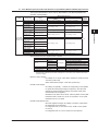
Manual Title
MX100 Data Acquisition Unit
Operation Guide
Manual No.
Description
IM MX100-02E Describes concisely the handling of the
MX100 and the basic operations of the
MX100 Standard Software.
Precautions on the Use of the
IM MX100-71E Summarizes the usage precautions of the
MX100/MW100
MX100/MW100.
MX100/MW100 Data Acquisition Unit IM MX100-72E Describes concisely the installation and
Installation and Connection Guide
wiring procedures of the MX100/MW100.
Control of pollution caused by
IM MX100-91C Describes control of pollution caused by
MX100/MW100 products
the product.
MX100 Standard Software User’s
IM MX180-01E Describes the functions and operations of
Manual
the MX100 Standard Software that comes
standard with the MX100 main module.
Notes
• When configuring an MX100 system, the versions of the instruments used in the
system indicated by the hardware style number and software release number must
meet the following conditions.
• The main module style number must be greater than or equal to the style numbers
of any input/output modules.
• The PC software release number must be greater than or equal to the style number
of the main module.
Certain functions may become disabled on instruments or software that do not
meet these conditions, or the system may not be able to be built.
• This manual describes MX100 style number “S3.” Check the style number on the
name plate.
• The contents of this manual are subject to change without prior notice as a result of
continuing improvements to the instrument’s performance and functions.
• Every effort has been made in the preparation of this manual to ensure the accuracy
of its contents. However, should you have any questions or find any errors, please
contact your nearest YOKOGAWA representative, dealer, or sales office.
• Copying or reproducing all or any part of the contents of this manual without the
permission of Yokogawa Electric Corporation is strictly prohibited.
• The TCP/IP software of this product and the document concerning the TCP/IP software
have been developed/created by YOKOGAWA based on the BSD Networking Software,
Release 1 that has been licensed from the University of California at Berkeley.
Trademarks
• DAQMASTER is a registered trademark of Yokogawa Electric Corporation.
• Microsoft and Windows are registered trademarks or trademarks of Microsoft
Corporation in the United States and/or other countries.
• Adobe and Acrobat are registered trademarks or trademarks of Adobe Systems
Incorporated.
• Company and product names that appear in this manual are registered trademarks or
trademarks of their respective holders.
• The company and product names used in this manual are not accompanied by the
registered trademark or trademark symbols (® and ™).
Revisions
1st Edition: May, 2003
2nd Edition: November, 2004 3rd Edition: June, 2006
4th Edition: February, 2008 5th Edition: March, 2012
5th Edition: March 2012 (YK)
All Rights Reserved, Copyright © 2003 Yokogawa Electric Corporation
IM MX100-01E
Safety Precautions
About This Manual
• Please pass this manual to the end user.
• Read this manual thoroughly and have a clear understanding of the product before operation.
• This manual explains the functions of the product. It does not guarantee that the product will suit a particular
purpose of the user.
• Under absolutely no circumstances may the contents of this manual be transcribed or copied, in part or in
whole, without permission.
• The contents of this manual are subject to change without prior notice.
• Every effort has been made in the preparation of this manual to ensure the accuracy of its contents. However,
should you have any questions or find any errors or omissions, please contact your nearest YOKOGAWA
dealer.
Precautions Related to the Protection, Safety, and Alteration of the Product
• The following safety symbols are used on the product and in this manual.
Danger. Refer to the user’s manual. This symbol appears on dangerous locations on the
instrument which require special instructions for proper handling or use. The same symbol
appears in the corresponding place in the manual to identify those instructions.)
Functional ground terminal (do not use this terminal as a protective ground terminal.)
Protective grounding terminal
Alternating current
• For the protection and safe use of the product and the system controlled by it, be sure to follow the
instructions and precautions on safety that are stated in this manual whenever you handle the product.
Take special note that if you handle the product in a manner that violates these instructions, the protection
functionality of the product may be damaged or impaired. In such cases, YOKOGAWA does not guarantee
the quality, performance, function, and safety of product.
• When installing protection and/or safety circuits such as lightning protection devices and equipment for the
product and control system or designing or installing separate protection and/or safety circuits for fool-proof
design and fail-safe design of the processes and lines that use the product and the control system, the user
should implement these using additional devices and equipment.
• If you are replacing parts or consumable items of the product, make sure to use parts specified by
YOKOGAWA.
• This product is not designed or manufactured to be used in critical applications that directly affect or threaten
human lives. Such applications include nuclear power equipment, devices using radioactivity, railway
facilities, aviation equipment, air navigation facilities, aviation facilities, and medical equipment. If so used, it
is the user’s responsibility to include in the system additional equipment and devices that ensure personnel
safety.
• Do not modify this product.
ii
IM MX100-01E
Safety Precautions
WARNING
Use the Correct Power Supply
Ensure that the source voltage matches the voltage of the power supply before turning ON the power.
Connect the Protective Grounding Terminal
Make sure to connect the protective grounding to prevent electric shock before turning ON the power.
Do Not Impair the Protective Grounding
Never cut off the internal or external protective earth wire or disconnect the wiring of the protective earth
terminal. Doing so invalidates the protective functions of the instrument and poses a potential shock hazard.
Do Not Operate with Defective Protective Grounding or Fuse
Do not operate the instrument if the protective earth or fuse might be defective. Make sure to check them
before operation.
Do Not Use in the Presence of Flammable Liquids, Vapors, and Dust
Do not use the instrument in the presence of flammable liquids, vapors, and dust. Operation in such
environments constitutes a safety hazard.
Do Not Remove Covers
The cover should be removed by YOKOGAWA’s qualified personnel only. Opening the cover is dangerous,
because some areas inside the instrument have high voltages.
Ground the Instrument before Making External Connections
Connect the protective grounding before connecting to the item under measurement or to an external control
unit.
Avoid Damage to the Protective Structure
Operating the instrument in a manner not described in this manual may damage its protective structure.
CAUTION
This instrument is a Class A product. Operation of this instrument in a residential area may cause radio
interference, in which case the user is required to take appropriate measures to correct the interference.
Exemption from Responsibility
• YOKOGAWA makes no warranties regarding the product except those stated in the WARRANTY that is
provided separately.
• YOKOGAWA assumes no liability to any party for any loss or damage, direct or indirect, caused by the user
or any unpredictable defect of the product.
Software Handling Precautions
• YOKOGAWA makes no warranties regarding the software accompanying this product except those stated in
the WARRANTY that is provided separately.
• Use the software on a single PC.
• You must purchase another copy of the software if you are to use the software on another PC.
• Copying the software for any purposes other than backup is strictly prohibited.
• Please store the original media containing the software in a safe place.
• Reverse engineering, such as decompiling of the software, is strictly prohibited.
• No portion of the software supplied by YOKOGAWA may be transferred, exchanged, sublet, or leased for use
by any third party without prior permission by YOKOGAWA.
IM MX100-01E
iii
Conventions Used in This Manual
Unit
k
K
Denotes 1000.
Denotes 1024. Example: 5 KB (file size)
Safety Markings
The following markings are used in this manual.
iv
Refer to corresponding location on the instrument. This symbol
appears on dangerous locations on the instrument which require
special instructions for proper handling or use. The same symbol
appears in the corresponding place in the manual to identify those
instructions.
WARNING
Calls attention to actions or conditions that could cause serious injury
or death to the user, and precautions that can be taken to prevent
such occurrences.
CAUTION
Calls attentions to actions or conditions that could cause light injury to
the user or damage to the instrument or user’s data, and precautions
that can be taken to prevent such occurrences.
Note
Calls attention to information that is important for proper operation of
the instrument.
IM MX100-01E
1
Contents
Safety Precautions............................................................................................................................ ii
Conventions Used in This Manual.................................................................................................... iv
Chapter 1 Explanation of Functions
1.1
1.2
1.3
1.4
1.5
1.6
1.7
IM MX100-01E
Overview of the MX100...................................................................................................... 1-1
Main Module (MX100-E).................................................................................................... 1-2
Input/Output Modules........................................................................................................ 1-2
Base Plate (MX150).......................................................................................................... 1-5
PC Software....................................................................................................................... 1-6
Main Module Functions...................................................................................................... 1-7
Communications................................................................................................................ 1-7
Measurement..................................................................................................................... 1-7
Filters................................................................................................................................. 1-9
Computation...................................................................................................................... 1-9
Remote RJC (RRJC)......................................................................................................... 1-9
Alarms ............................................................................................................................ 1-10
Contents Displayed on the 7-Segment LED.....................................................................1-11
Saving Data to the CF Card............................................................................................ 1-12
Functions of the 4-CH, High-Speed Universal Input Module........................................... 1-15
Input Type and Measurement Range.............................................................................. 1-15
Measurement Interval, Integration Time, and Filter......................................................... 1-16
Measurement Synchronization........................................................................................ 1-16
Common Mode Voltage................................................................................................... 1-16
Functions of the 10-CH, Medium-Speed Universal Input Module.................................... 1-17
Input Type and Measurement Range.............................................................................. 1-17
Measurement Interval, Integration Time, and Filter......................................................... 1-18
Measurement Synchronization........................................................................................ 1-18
Common Mode Voltage................................................................................................... 1-18
Functions of the 30-CH, Medium-Speed DCV/TC/DI Input Module................................. 1-19
Input Type and Measurement Range.............................................................................. 1-19
Measurement Interval, Integration Time, and Filter......................................................... 1-20
Measurement Synchronization........................................................................................ 1-20
Common Mode Voltage................................................................................................... 1-20
Functions of the 6-CH, Medium-Speed Four-Wire RTD Resistance Input Module.......... 1-21
Input Type and Measurement Range.............................................................................. 1-21
Measurement Interval, Integration Time, and Filter......................................................... 1-22
Measurement Synchronization........................................................................................ 1-22
Common Mode Voltage................................................................................................... 1-22
Functions of the 4-CH, Medium-Speed Strain Input Module (-B12, -B35, and -NDI)...... 1-23
Measurement Range....................................................................................................... 1-23
Measurement Interval, Integration Time, and Filter......................................................... 1-23
Measurement Synchronization........................................................................................ 1-23
Common Mode Voltage................................................................................................... 1-23
Initial Balancing (Initial Unbalance Value Adjustment)..................................................... 1-24
Scaling Settings When Using a Strain Gauge Type Sensor ........................................... 1-25
Compensation When the Gauge Factor Differs............................................................... 1-26
2
3
4
5
Index
Contents
1.8
Functions of the 10-CH, High-Speed Digital Input Module (-D05, -D24)......................... 1-27
Measurement Interval...................................................................................................... 1-27
Filters............................................................................................................................... 1-27
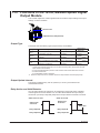
1.9 Functions of the 8-CH, Medium-Speed Analog Output Module....................................... 1-28
Output Type..................................................................................................................... 1-28
Output Range.................................................................................................................. 1-28
Output Update Interval.................................................................................................... 1-28
Operation When Errors Occur upon Startup................................................................... 1-28
Output Operation During Calibration............................................................................... 1-28
1.10 Functions of the 8-CH, Medium-Speed PWM Output Module......................................... 1-29
Output Type..................................................................................................................... 1-29
Output Waveform............................................................................................................. 1-29
Pulse Interval................................................................................................................... 1-29
Output Update Interval.................................................................................................... 1-29
Output Range.................................................................................................................. 1-29
Operation When Errors Occur upon Startup................................................................... 1-29
1.11 Operation of the 8-CH Medium-Speed Analog Output Module and the 8-CH Medium Speed
PWM Output Module........................................................................................................ 1-30
Output Selection When Errors Occur upon Startup......................................................... 1-30
Output Status................................................................................................................... 1-30
Output on Disabled Channels.......................................................................................... 1-30
Output Operation per Settings and Setting Changes ..................................................... 1-30
Steady Output Operation................................................................................................. 1-32
Output When Abnormal, or after Recovery from Abnormality.......................................... 1-33
1.12 Functions of the 10-CH, Medium-Speed Digital Output Module...................................... 1-36
Output Type..................................................................................................................... 1-36
Output Update Interval.................................................................................................... 1-36
Relay Action and Hold Behavior...................................................................................... 1-36
Chapter 2 Installation and Wiring
2.1
2.2
2.3
2.4
vi
Handling Precautions......................................................................................................... 2-1
Installation.......................................................................................................................... 2-2
Installation Location........................................................................................................... 2-2
Installation Procedure........................................................................................................ 2-2
Attaching the Modules....................................................................................................... 2-4
Attachment Procedure....................................................................................................... 2-4
Attachment Positions and Channel Numbers.................................................................... 2-5
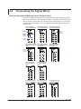
Connecting the Signal Wires.............................................................................................. 2-6
Terminal Arrangement Markings on the Terminal Cover.................................................... 2-6
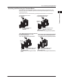
Attaching and Removing the Terminal Block..................................................................... 2-7
Attaching Plates with Screw Terminals and Plates with Clamped Terminals for Current... 2-8
Screw Terminal Block........................................................................................................ 2-8
General Precautions When Wiring the Input/Output Signal Wires.................................... 2-9
Wiring Procedure..............................................................................................................2-11
Wiring the Universal Input Module and DCV/TC/DI Input Module....................................2-11
Wiring the Four-Wire RTD Resistance Input Modules..................................................... 2-12
Wiring the Strain Input Modules...................................................................................... 2-12
Wiring the Digital Input Modules (-D05, -D24)................................................................. 2-16
Wiring the Analog Output Modules.................................................................................. 2-17
Wiring the PWM Output Modules.................................................................................... 2-17
Wiring the Digital Output Modules................................................................................... 2-18
IM MX100-01E
Contents
2.5
2.6
2.7
2.8
Power Connection and ON/OFF...................................................................................... 2-19
Connections with the Power Cord (Power Supply/Cord Basic Specification Code 1*)2-19
Wiring the Power Supply Terminal (Power Supply/Cord Basic Specification Code 1W) 2-20
Turning ON/OFF the Power Switch................................................................................. 2-21
Connecting the Ethernet Cable........................................................................................ 2-22
Connection Procedure..................................................................................................... 2-22
Checking the Communication Status.............................................................................. 2-23
Initializing the Settings..................................................................................................... 2-23
Measures against Noise on the MX100........................................................................... 2-24
Integrating A/D Converter................................................................................................ 2-24
First-Order Lag Filter....................................................................................................... 2-26
Handling of the CF Card.................................................................................................. 2-27
Handling Precautions of the CF Card.............................................................................. 2-27
Inserting the CF Card...................................................................................................... 2-27
Ejecting the CF Card....................................................................................................... 2-27
3.2
3.3
3.4
3.5
Error Display on the 7-Segment LED and Corrective Actions............................................ 3-1
Errors at Power ON........................................................................................................... 3-1
System Errors.................................................................................................................... 3-1
Module Errors.................................................................................................................... 3-2
Media-Related Errors......................................................................................................... 3-2
Communication Errors....................................................................................................... 3-2
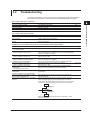
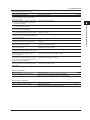
Troubleshooting................................................................................................................. 3-3
Calibration.......................................................................................................................... 3-6
Range Calibration of DC Voltage, RTD, Resistance, Strain, and Analog Output.............. 3-6
Calibration of Temperature Measurements using Thermocouples...................................3-11
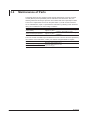
Maintenance of Parts....................................................................................................... 3-12
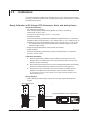
MX100 Maintenance and Test Using Communication Commands.................................. 3-13
Connecting the Main Module and the PC........................................................................ 3-13
Setting the Terminal Emulator.......................................................................................... 3-13
List of Maintenance/Test Commands.............................................................................. 3-13
Specifications of the Maintenance/Test Port.................................................................... 3-13
Chapter 4 Specification
4.1
4.2
4.3
4.4
4.5
4.6
4.7
4.8
4.9
4.10
4.11
4.12
4.13
IM MX100-01E
2
3
4
5
Index
Chapter 3 Troubleshooting and Maintenance
3.1
1
Common Specifications..................................................................................................... 4-1
Main Module (MX100-E) Specifications............................................................................. 4-2
Base Plate (MX150) Specifications.................................................................................... 4-7
4-CH, High-Speed Universal Input Module (MX110-UNV-H04) Specifications.................. 4-8
10-CH, Medium-Speed Universal Input Module (MX110-UNV-M10) Specifications........ 4-12
30-CH, Medium-Speed DCV/TC/DI Input Module (MX110-VTD-L30) Specifications...... 4-16
6-CH, Medium-Speed Four-Wire RTD Resistance Input Module (MX110-V4R-M06)
Specifications................................................................................................................... 4-20
4-CH, Medium-Speed Strain Input Module (MX112) Specifications................................ 4-24
10-CH, High-Speed Digital Input Module (MX115) Specifications................................... 4-26
8-CH, Medium-Speed Analog Output Module (MX120-VAO-M08) Specifications........... 4-27
8-CH, Medium-Speed PWM Output Module (MX120-PWM-M08) Specificaions............. 4-29
Specifications Common to the 8-CH Medium-Speed Analog Output Module and the 8-CH
Medium Speed PWM Output Module (MX120)................................................................ 4-32
10-CH, Medium-Speed Digital Output Module (MX125) Specifications........................... 4-33
vii
Contents
Chapter 5 Dual Save Functions (/DS Option)
5.1
5.2
5.3
Overview of Functions........................................................................................................ 5-1
Explanation of Functions.................................................................................................... 5-2
CF Card Data File.............................................................................................................. 5-9
Index
viii
IM MX100-01E
Chapter 1
1.1
Explanation of Functions
1
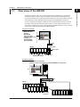
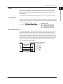
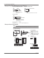
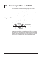
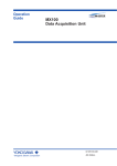
Overview of the MX100
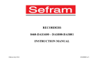
One-to-one connection
2
3
4
5
PC
• MX100 Standard
Software
• MXLOGGER
(sold separately)
• Software created using
the API for the
MX100/DARWIN
(sold separately)
Index
Hub
Base plate
MX100
MX100
Ethernet port
Input/Output module
Main module
One-to-N connection
• MXLOGGER (sold separately)
• Software created using the API for the MX100/DARWIN (sold separately)
PC
Hub
MX100
MX100
MX100
MX100
Connect up
to 20 units
IM MX100-01E
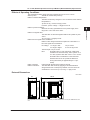
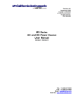
Explanation of Functions
The MX100 consists of the main module equipped with an Ethernet port, input/output
modules that perform input or output of signals, and the base plate that attaches and
connects all of these. By connecting the main module and a PC via the Ethernet interface
and installing one of the dedicated software programs indicated below onto the PC,
you can configure the acquisition conditions for the measured data from the PC as well
as monitor and acquire the measured data on the PC. One to twenty MX100s can be
connected to a single PC (one unit using the MX100 Standard Software, or one to twenty
units (or up to 1200 input channels) using MXLOGGER).
1-1
1.1 Overview of the MX100
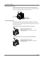
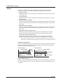
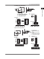
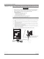
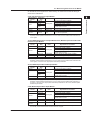
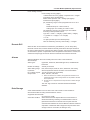
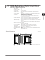
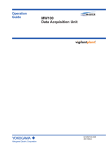
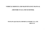
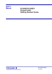
Main Module (MX100-E)
The main module is equipped with a power supply connector, a power switch, an
Ethernet port, a CF card slot, and other parts. It controls the power supply to and the
control of each input/output module, communications with a PC, data storage to the CF
card when communication is disconnected, and other functions.
Ethernet port
CF card
slot
Power switch
Power connector or
screw terminal
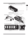
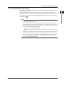
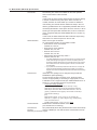
Input/Output Modules
The following twelve types of modules are available. A plate with screw terminals
and separately installed screw terminal block (both sold separately) are available as
accessories for the 10-CH, Medium-Speed Universal Input Module and the 10-CH, HighSpeed Digital Input Module.
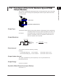
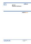
4-CH, High-Speed Universal Input Module (MX110-UNV-H04)
• Minimum measurement interval: 10 ms
• Maximum number of inputs: 4 inputs
• Input types: DC voltage, TC, 3-wire RTD, and DI (LEVEL,
non-voltage contact)
10-CH, Medium-Speed Universal Input Module (MX110-UNV-M10)
1-2
• Minimum measurement interval: 100 ms
• Maximum number of inputs: 10 inputs
• Input types: DC voltage, TC, 3-wire RTD, and DI (LEVEL,
non-voltage contact)
IM MX100-01E
1.1 Overview of the MX100
1
Explanation of Functions
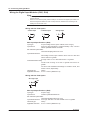
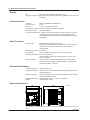
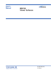
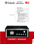
30-CH, Medium-Speed DCV/TC/DI Input Module
(MX110-VTD-L30, MX110-VTD-L30/H3)
• Minimum measurement interval: 500 ms
• Maximum number of inputs: 30 inputs
• Input types: DC voltage, TC, and DI (LEVEL, non-voltage
contact)
2
3
4
5
MX110-VTD-L30
(clamp terminal)
Index
MX110-VTD-L30/H3
(M3 screw terminal)
6-CH, Medium-Speed Four-Wire RTD Resistance Input Module
(MX110-V4R-M06)
• Minimum measurement interval: 100 ms
• Maximum number of inputs: 6 inputs
• Input types: DC voltage, 4-wire RTD, 4-wire resistance,
and DI (LEVEL, non-voltage contact)
4-CH, Medium-Speed Strain Input Module
(MX112-B12-M04, MX112-B35-M04)
• Minimum measurement interval: 100 ms
• Maximum number of inputs: 4 inputs
• Input system: floating balanced input (isolation between
channels)
4-CH, Medium-Speed Strain Input Module (MX112-NDI-M04)
• Minimum measurement interval: 100 ms
• Maximum number of inputs: 4 inputs
• Input system: floating balanced input
(non-isolation between channels)
IM MX100-01E
1-3
1.1 Overview of the MX100
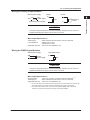
10-CH, High-Speed Digital Input Module (MX115-D05-H10)
• Minimum measurement interval: 10 ms
• Maximum number of inputs: 10 inputs
• Input types: DI (non-voltage contact, open collector, and
5-V logic)
10-CH, High-Speed Digital Input Module (MX115-D24-H10)
• Minimum measurement interval: 10 ms
• Maximum number of inputs: 10 inputs
• Input types: DI (24-V logic)
8-CH, Medium-Speed Analog Output Module (MX120-VAO-M08)
• Output update interval: 100 ms (shortest)
• Maximum number of inputs: 8 outputs
• Output type: DC voltage, DC current
8-CH, Medium-Speed PWM Output Module (MX120-PWM-M08)
• Output update interval: 100 ms (shortest)
• Maximum number of inputs: 8 outputs
• Output type: PWM
1-4
IM MX100-01E
1.1 Overview of the MX100
1
10-CH, Medium-Speed Digital Output Module (MX125-MKC-M10)
Explanation of Functions
2
• Output update interval: 100 ms (shortest)
• Maximum number of outputs: 10 outputs
• Output type: A contact (SPST)
3
4
5
CAUTION
The 10-CH, Pulse Input Module (MX114-PLS-M10) cannot be used on the MX100
for the reasons below. Please use the 10-CH, Pulse Input Module with the MW100.
• Values measured on the MX100 are acquired by the MX100 Standard Software
or MXLOGGER (sold separately).
Pulse measurement values are transferred to the PC software every
measurement interval per the MX100 clock. For pulse integral values, pulse
measurement values sent from the MX100 per the PC clock are integrated on
the PC.
The error on the MX100 and PC clocks is different. Therefore discrepancies
arise in the number of measurements and time, and the simultaneity of other
measured values and pulse measured values is lost, along with the accuracy of
pulse integral values.
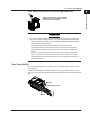
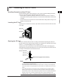
Base Plate (MX150)
The base plate is equipped with connectors for connecting the main module and input/
output modules.
Six different base plates are available to hold one to six input/output modules. You can
rack-mount or panel-mount the MX100 by attaching a DIN rail mount bracket to this base
plate.
Base plate
DIN rail mount bracket
DIN rail
IM MX100-01E
1-5
Index
1.1 Overview of the MX100
PC Software
One MX100 can be connected to a PC, and the MX100 Standard Software (that can
acquire measured data) is included. The MX100 Standard Software consists of the
three software programs below. For details about the software functions and operating
procedures, see the MX100 Standard Software User’s Manual (IM MX180-01E). When
configuring a system using the MX100, the software release number and hardware style
number matching conditions must be met (see “Notes” on page i).
Integration Monitor
Enables you to connect or disconnect communications, configure acquisition conditions
and display conditions of the measurement channels, set up computations channels,
monitor measured and computed data, save measured and computed data, and carry
out other operations.
Viewer
Enables you to display measured and computed data that has been saved, read
values and perform statistical computation over an area using cursors, and convert the
measured and computed data into various file formats such as Excel.
Calibrator
This program is used to calibrate the MX100 universal input modules, DCV/TC/DI input
modules, 4-wire RTD resistance input module, strain input modules, and analog output
module.
1-6
IM MX100-01E
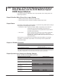
1.2
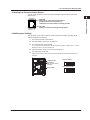
1
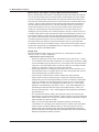
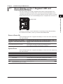
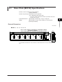
Main Module Functions
Explanation of Functions
2
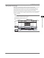
The main module is the heart of the MX100.
DATA ACQUISITION UNIT
ETHERNET
CF card
slot
SW
ON
1 2 3 4 5 6 7 8
POWER
10BASE - T
100BASE - TX
100 - 240V AC
70VA MAX
50/60Hz
Do not operate without reading safety precaution in users manual.
Ethernet port
7-segment LED
Dipswitch*
Power switch
3
* Normally, turn all switches ON.
If the /DS option function is
enabled (see section 5.1),
you can initialize settings
(see section 2.6) and perform
other functions.
4
ON
1
Power connector or
screw terminal
Functional ground terminal
2
3
4
5
6
7
5
8
Index
Communications
The main module is equipped with one auto-negotiating 10BASE-T/100BASETX Ethernet port. The LEDs at the upper-left and lower-left of the port indicate the
communication status of the Ethernet interface.
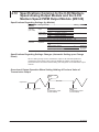
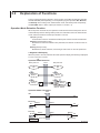
Measurement
The main module acquires measured data sampled at specified intervals on each input
module is acquired. Correcting computation, conversion to physical quantities, and other
processes are performed on the acquired measured data, followed by transmission
of measured data to a PC via the Ethernet interface at 100-ms intervals (shortest).
Even if sampled at intervals less than 100 ms (10 ms or 50 ms), the data is transmitted
collectively at 100-ms intervals. In addition, the main module receives output commands
sent from the PC as necessary and generates signal output instructions to the output
modules.
100 ms
100 ms
100 ms
Data sampling when the
measurement interval is 10 ms
Creation of output data
Output by an output request from the PC
Timing when the creation of the
output data starts
Synchronization of Measurements
• Synchronization between modules
If set to the same measurement interval, measurements made by input modules in the
same acquisition unit are synchronized.
• Synchronization between channels
On the 4-CH, High-Speed Universal Input modules and 10-CH, high speed digital
input modules (-D05 and -D24), measurements between channels are synchronized.
On the 10-CH, Medium-Speed Universal Input modules, 30-CH, Medium-Speed
DCV/TC/DI Input Modules, 6-CH Medium-Speed Four-Wire RTD Resistance
Input modules, and 4-CH, Medium-Speed Strain Input modules (-B12, -B35, and
-NDI), measurements are made sequentially one channel at a time. Therefore,
measurements are not synchronized between channels (we can consider them
synchronized within the measurement interval).
IM MX100-01E
1-7
1.2 Main Module Functions
Measurement Time (When Using the MX100 Standard Software)
When a measurement start request or a measurement data output request is made by
a PC to the main module, the PC’s time information is transmitted to the main module.
The main module generates measurement time using the internal clock based on the
time when the measurement start request is received. When the measured data is sent
to the PC, the PC’s time information along with the measurement time information on
the main module is returned to the PC. The time information used in the monitoring
of the measured data on the PC is that of the main module. When measurement is
made over an extended time, the time between the PC and main module may be
misaligned (up to 60 seconds in one week excluding the accuracy of the PC clock). As
a remedy to this problem, when the measured data is recorded (saved) on the PC, the
PC’s time information is stored along with the measurement time information on the
main module. When the Viewer of the MX100 Standard Software is used to open the
recorded measurement data, the “time synchronization” function can be used to correct
the measurement time relative to the PC’s time based on the PC’s time information.
For details on the time synchronization function, see the Technical Information, MX100
Performance Specifications (TI 04M08B01-00E). For information on obtaining a copy,
contact your nearest YOKOGAWA dealer.
Range Over
When the MW100 detects a range over (see below) on a measurement or MATH
channel, “+Over” or “-Over” is displayed.
• Measurement channel range over
• During DC voltage input, strain input, and resistance (20 Ω, 200 Ω, etc.), a range
over is detected if the value that is measured on a measurement channel is outside
of the measurable range by more than ±5%. For example, when the measurement
range is 2 V, the measurable range is -2.0000 to 2.0000 V. If the voltage exceeds
2.2000 V or goes below -2.2000 V, a range over is detected.
• During high-resolution DC voltage input and pulse input, a value less than 0% of
the measurable range is a negative range over, and a value greater than 105% of
the measurable range is a positive range over.
• If the input type is thermocouple or RTD, excluding the cases where the
thermocouple or RTD has a special range, a range over is detected when the
temperature goes more than approximately 10°C above or below the measurable
range. For example, when the measurement range is set to R, the measurable
range is 0.0 to 1760.0°C. If the temperature exceeds 1770.0°C, “+Over” will be
displayed. If the temperature goes below -10.0°C, “-Over” will be displayed. The
special ranges mentioned here are ranges such as KpvsAu7Fe or J263. If you
are using a special range, “-Over” will be displayed if the temperature goes below
approximately 0°C.
• On channels that use linear scaling, the range-over values, after removing the
decimal point, are above 32000 and below -32000. However, even if the measured
value is within ±30000, if it is a range-over value according to the previous range, it
will be handled as a range-over value.
• When you are performing differential computation between channels (see
"Computation" on next page), if the measured value is outside of the measurable
range, a range over will be detected. When you are using a sensor such as a
thermocouple, the measurable range when performing differential computation
between channels may be larger than the measurable range when not performing
differential computation between channels.
1-8
IM MX100-01E
1.2 Main Module Functions
1
Filters
2
3
Time constant = measurement interval × N (where N = 5, 10, 20, 25, 40, 50, or 100)
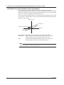
Computation
Difference computation between channels and linear scaling are possible. Linear scaling
converts the measured values to values suitable for a particular purpose (scaled values)
using the following equation.
Scale value =
(X – SPmin) × (SCmax – SCmin)
SPmax – SPmin
+ SCmin
Index
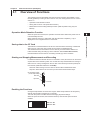
In measuring temperature with thermocouples within the same unit, when the item to be
measured is located at a great distance, you can setup relay terminals near the item,
measure the temperature of the relay terminal section using thermocouples (reference
channel), and use the resultant value as the reference junction compensation value for
the temperature measurement. By connecting a copper wire between the relay terminal
and input terminal of the input module, and a thermocouple between the DUT and relay
terminal, you can measure the temperature of the DUT without the need for a large
amount of expensive thermocouples.
Input terminal
Relay terminal (to be furnished by the user)
Thermocouple*
Reference channel
Copper wire
Thermocouple*
Copper wire
Thermocouple*
* Use the same type of thermocouples.
IM MX100-01E
4
5
X: Measured value
SPmax: Specified span maximum
SPmin: Specified span minimum
SCmax: Specified scale maximum
SCmin: Specified scale minimum
Remote RJC (RRJC)
MX100
Explanation of Functions
The main module is equipped with a first-order lag filter (see section 2.7, “Measures
against Noise on the MX100”. You can select a time constant (time until 63.2% of the
output value is reached) corresponding to the measurement interval indicated in the
equation below.
1-9
1.2 Main Module Functions
Alarms
This function outputs alarms when measured or computed values* meet certain
conditions. Select up to four alarms of the following six types on each channel.
• Upper limit alarm
Generates an alarm when the measured or computed value* is greater than or equal
to the alarm value.
• Lower limit alarm
Generates an alarm when the measured or computed value* is less than or equal to
the alarm value.
• Differential upper limit alarm
Generates an alarm when differential input values (difference between the measured
value of a channel and that of the reference channel) are greater than or equal to the
alarm value.
• Differential lower limit alarm
Generates an alarm when differential input values (difference between the measured
value of a channel and that of the reference channel) are less than or equal to the
alarm value.
• Upper limit on rate-of-change alarm*
Generates an alarm if the amount of change in the computed value in the rising
direction exceeds the alarm value within the rate-of-change detection interval.
• Lower limit on rate-of-change alarm*
Generates an alarm if the amount of change in the computed value in the falling
direction exceeds the alarm value within the rate-of-change detection interval.
* When using computed value alarms, do not disconnect the MX100 and the PC software.
Alarms will not occur because the Computation function will not work on the MX100 by itself.
Alarm Value Hysteresis
You can set a width (hysteresis) to the values used to activate and release alarms. Alarm
hysteresis can prevent frequent activation and release of alarms when the measured
value is unstable around the alarm value.
Lower limit alarm
Upper limit alarm
Alarm activated
Alarm
setting
Measured value
Alarm release
Hysteresis
Measured vale
Alarm release
Alarm activated
Alarm setting
Alarm Output Timing
Alarms occur at each measurement interval based on the alarm settings. However when
the measurement interval is 10 or 50 ms, alarms occur at 100 ms intervals based on all
of the data.
1-10
IM MX100-01E
1.2 Main Module Functions
1
Contents Displayed on the 7-Segment LED
2
Unit Number Display
When connecting to the MX100 Standard Software, the unit number is fixed to 00 and
displayed as “
is displayed as “
.” When connecting to MXLOGGER (sold separately), the unit number
” to “
.”
Display of the Self-Test Operation at Power On
When the power is turned ON the dip switch indicator lights (normally displays “
”,
or “
” when the /DS option functions enabled), the operation ready indicator lights
(the
display, and others), then the self-test is carried out. While the self-test is in
progress, the following symbols are alternately displayed.
” is
Operation Mode Display
The MX100 has three operation modes: idle mode, measurement mode, and backup
mode (measured data saved to a CF card due to the disconnection of communications).
The modes are displayed as shown below. In the figure below,
indicates the unit
number. If the unit number is not 00, the specified unit number is displayed.
• Idle mode
• Measurement mode
• Backup mode
Two zeroes
Two zeroes and a dot
Two zeroes and two dots
Display When Operation Is Complete
The figure below shows the display that appears when an operation such as IP address
configuration and measurement condition change is completed. In the figure below, the
unit number is “
.” If the unit number is not 00, the specified unit number is displayed.
Turns off
for 1 second
Display during Processing
The displays shown below repeats when the CF card is accessed, when the CF card is
being formatted, or when calibration is taking place.
Unit Confirmation Display
The figure below shows the display that appears when you confirm the MX100 that is
connected using the MX100 Standard Software or MXLOGGER (sold separately). The
word –CALL– flows through the display from left to right.
Operation Error Display
For details on the display and meaning of errors, see section 3.1, “Error Display on the
7-Segment LED and Corrective Actions.”
IM MX100-01E
3
4
5
Index
Operation Mode Hold Function Display (Only When the /DS Option
Function is Installed)
Following the self-check, the /DS option function execution confirmation (“
displayed.
Explanation of Functions
The two-digit 7-segment LED displays the unit number, operating status, operation
complete, and operation error of the MX100.
1-11
1.2 Main Module Functions
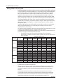
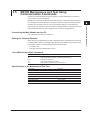
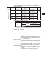
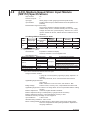
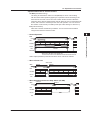
Saving Data to the CF Card
Data Saving When Communication Is Disconnected and Dual Save Function
If communication is disconnected while the PC is recording (saving) measured data and
a 60-s timeout* expires, the measured data is saved to the CF card at 60-s intervals.
When the save operation is started, a file is created for each measurement interval
(referred to as the monitor interval on the MX100 Standard Software). As the save
operation progresses and the file for the shortest measurement interval reaches 5 MB,
the file is closed. At the same time, files of other measurement intervals (files that have
not reached 5 MB) are also closed. Then, a new file is created for each measurement
interval setting once again, and the save operation continues. When the communication
with the PC resumes and acquisition of measured data resumes, the save operation
automatically stops.
If the /DS option function (see “Saving Data to the CF Card” in section 5.1) is enabled,
saving of measured data to the CF card is linked to recording on the PC, even if
communication is disconnected.
To manually stop the operation, press the access stop switch (see “Ejecting the CF Card”
in section 2.8) located above the CF card slot on the main module.
The table below shows the interval (a guideline) over which data can be saved to the CF
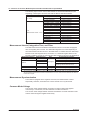
card when one type of measurement interval is used.
* The time from the point when the communication between the PC and MX100 is
disconnected and acquisition of measured data is stopped to the point when data storage to
the CF card starts.
Number of Measurement
Saved CHs
Interval
10 CHs
24 CHs
60 CHs
10 ms
50 ms
100 ms
200 ms
500 ms
1s
2s
10 ms
50 ms
100 ms
200 ms
500 ms
1s
2s
10 ms
50 ms
100 ms
200 ms
500 ms
1s
2s
Capacity of the CF card
32 MB
64 MB
128 MB
256 MB
512 MB
1 GB
2 GB
(6 files)
(12 files) (34 files) (49 files) (98 files) (196 files) (390 files)
2.1 hours 4.2 hours 8.7 hours 17.5 hours 35.3 hours
2.9 days
5.9 days
10.9 hours 21.8 hours
1.8 days
3.6 days
7.3 days
14 days
29 days
21.8 hours
1.8 days
3.6 days
7.2 days
14 days
29 days
59 days
1.8 days
3.6 days
7.2 days
14 days
29 days
59 days
118 days
4.5 days
9 days
18 days
36 days
73 days 147 days 295 days
9 days
18 days
36 days
72 days 147 days 295 days 591 days
18 days
36 days
72 days 145 days 294 days 591 days 1182 days
54 min. 1.8 hours 3.6 hours 7.3 hours 14.7 hours 29.5 hours
2.4 days
4.5 hours
9 hours
18 hours
1.5 days
3 days
6.1 days
12 days
9 hours
18 hours
1.5 days
3 days
6.1 days
12 days
24 days
18.1 hours
1.5 days
3 days
6.1 days
12 days
24 days
49 days
1.8 days
3.7 days
7.5 days
15 days
30 days
61 days 122 days
3.7 days
7.5 days
15 days
30 days
61 days 123 days 246 days
7.5 days
15 days
30 days
60 days 122 days 246 days 492 days
21 min.
42 min. 1.4 hours 2.9 hours 5.8 hours 11.7 hours 23.4 hours
1.8 hours 3.6 hours 7.2 hours 14.7 hours 29.4 hours
2.4 days
4.9 days
3.6 hours 7.2 hours 14.4 hours 29.4 hours
2.4 days
4.9 days
9.8 days
7.2 hours 14.4 hours 28.8 hours
2.4 days
4.9 days
9.8 days
19 days
18.1 hours
1.5 days
3 days
6 days
12 days
24 days
49 days
1.5 days
3 days
6 days
12 days
24 days
49 days
98 days
3 days
6 days
12 days
24 days
49 days
98 days 196 days
File Structure and Saved Channels
A file is created on the CF card for every measurement interval. The measurement
interval is the one specified as the monitor interval under Measurement Group in the
Acquisition Conditions screen of the MX100 Standard Software (not the recording
interval).
Measurement groups of the same monitoring interval are saved to the same file.
The channels saved to the file are those whose Monitor check boxes are selected in
the Channel screen (not those whose Record check boxes are selected). For other
specifications relating to saving of data, see “Data Storage” in section 4.2.
1-12
IM MX100-01E
1.2 Main Module Functions
Precautions When Using the CF Card
• Checking the CF Card Status
Before starting recording, check that the CF card is inserted into the slot, the
installation status is “Exists,” and that “Usable” is “Yes.”
When using the MX100 Standard Software, check that the Status display under CF
Card Information in the System screen is “Exists (Usable).” See “Explanation” in
section 2.2 of the MX100 Standard Software User’s Manual (IMMX180-01E).
When using the API for MX100/DARWIN, check the installation status and usability by
sending the status request command (getStatusDataMX).
Note
• If data saving has been restored after being disabled, due to a media-related error, check
that the installation status is “Exists,” and that Usable is “Yes.”
• If the CF card is inserted during recording and the installation status is “Exists” but Usable is
“No,” data cannot be saved (example 3 in the CF card operation diagram below).
• Operation of the CF Card
If you press the access stop switch (see “Ejecting the CF Card” in section 2.8) during
recording, data is not saved to the CF card even if communication is disconnected.
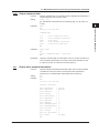
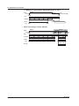
MX100 Operation and Status Relative to CF Card Operation
MX100
operation
status
Power
ON
MX100
operation
Idling
mode changes
CF card
operation
CF card
operation
ex. 1
CF card
operation
ex. 2
Comm.
Comm.
disconnected restart
Allowed
Insert CF card
Access stop switch ON
Useable “Yes”
Insert CF card
Access stop switch ON
Useable “Yes”
Useable “No”
Insert CF card
CF card
operation
ex. 3
Useable “Yes”
Status
Status
IM MX100-01E
Monitor
start
Allowed
Prohibited
Status
CF card
operation
ex. 3
Recording Monitor
stop
stop
Backup
Measurement
Status
Record
start
Monitor
start
Useable “No”
Insert CF card
Eject CF card
Useable “Yes”
Insert CF card
Useable “Yes”
Useable “No”
1-13
1
Explanation of Functions
On the MX100, measured data can only be saved to the CF card (backed up) when
recording of measured data to the PC via communications is turned OFF (unless the /DS
option function is active). In this case, saving of data to the CF card presumes that the
following conditions are met.
2
3
4
5
Index
1.2 Main Module Functions
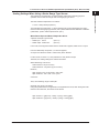
Log File Storage
In addition to the measured data that is saved when the communication with the PC is
disconnected, a log file of information related to the CF card operation and information of
power ON/OFF is saved to the CF card in text format (MX100MLG.TXT). The maximum
size of the log file is 40 KB. Up to 1021 events can be stored. When 1021 events are
exceeded, the event is deleted in order from the oldest information. The log is written
(overwritten to the same file name) to the CF card when you press the access stop
switch (see “Ejecting the CF Card” in section 2.8).
Information Saved to the Log File
•
•
•
•
•
•
Date/Time when the power is turn ON or OFF.
Date/Time when the CF card is inserted or ejected.
Save mode when data is saved (backup) and the start/stop log.
The file creation and deletion log.
Media-related errors.
The CF card formatting log.
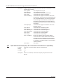
Log File Example
Yokogawa
Date
70/01/01
03/01/01
03/03/25
03/03/25
03/03/25
03/03/25
03/03/25
03/03/25
03/03/25
03/03/25
03/03/25
03/03/25
03/03/25
>>
DAQMASTER MX100 <Media Info>
Time
Status Message
00:00:00 Power
off
00:00:01 Power
on
10:12:13 Format ok
11:14:12 Backup start
11:14:12 Mode
rotary
11:14:13 Delete (--)
11:14:21 Create 32500000
11:14:36 Code
12 MF
11:14:36 Error
P3
11:14:54 Backup stop
11:15:18 Create MX100MLG
11:15:22 Card
out
11:15:25 Card
in
Time indicating that the settings
have been initialized*
Time after resetting the internal clock*
Media error (records the error code)
Most-recent information
Termination mark
* When the MX100 is initialized, the date/time on the MX100 is reset to 1970/01/01 00:00:00
once, then to the default value on the MX100 (2003/01/01 00:00:00). Then, when the PC
software is started and connection to the MX100 is made, the current date/time on the PC is
transmitted to the MX100. The MX100 is reset to the received date/time.
CF Card Specifications
Item
Capacity
Type
Format
File system
1-14
Specification
2 GB maximum
Type I or Type II
Supports quick (logical) format. 1 partition format (hard disk format) is possible
only through a command from the PC when the MX operation mode is idle.
FAT or FAT16
IM MX100-01E
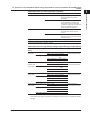
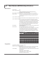
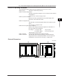
1.3
1
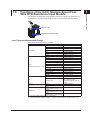
Explanation of Functions
Functions of the 4-CH, High-Speed Universal
Input Module
2
This module is equipped with four inputs and measures DC voltage, Thermocouple,
three-wire RTD, and digital input (DI) at a minimum measurement interval of 10 ms.
3
Terminal cover
4
5
Input terminal (clamp terminal)
Index
Input Type and Measurement Range
The following measurements are possible.
Input
DC voltage
Thermocouple
RTD
(Measurement current: 1 mA)
RTD
(Measurement current: 2 mA)
DI
IM MX100-01E
Measurement Range Type
20 mV
60 mV
200 mV
2V
6V
20 V
100 V
R
S
B
K
E
J
T
N
W
L
U
KPvsAu7Fe
Pt100
JPt100
Pt100 (high resolution)
JPt100 (high resolution)
Ni100 SAMA
Ni100 DIN
Ni120
Pt100
JPt100
Pt100 (high resolution)
JPt100 (high resolution)
Pt50
Cu10 GE
Cu10 L&N
Cu10 WEED
Cu10 BAILEY
J263B
Level
Contact input
Rated Measurement Range
–20.000 to 20.000 mV
–60.00 to 60.00 mV
–200.00 to 200.00 mV
–2.0000 to 2.0000 V
–6.000 to 6.000 V
–20.000 to 20.000 V
–100.00 to 100.00 V
0.0 to 1760.0°C
0.0 to 1820.0°C
–200.0 to 1370.0°C
–200.0 to 800.0°C
–200.0 to 1100.0°C
–200.0 to 400.0°C
0.0 to 1300.0°C
0.0 to 2315.0°C
–200.0 to 900.0°C
–200.0 to 400.0°C
0.0 to 300.0K
–200.0 to 600.0°C
–200.0 to 550.0°C
–140.00 to 150.00°C
–140.00 to 150.00°C
–200.0 to 250.0°C
–60.0 to 180.0°C
–70.0 to 200.0°C
–200.0 to 250.0°C
–200.0 to 250.0°C
–140.00 to 150.00°C
–140.00 to 150.00°C
–200.0 to 550.0°C
–200.0 to 300.0°C
–200.0 to 300.0°C
–200.0 to 300.0°C
–200.0 to 300.0°C
0.0 to 300.0K
Vth = 2.4 V
ON: 100 Ω or less,
OFF: 10 kΩ or more
1-15
1.3 Functions of the 4-CH, High-Speed Universal Input Module
The following inputs can be used on MXLOGGER or MX100/DARWIN API sold
separately. These inputs cannot be used with the MX100 Standard Software.
Input
DC voltage
Thermocouple
RTD
(Measurement current: 1 mA)
RTD
(Measurement current: 2 mA)
Measurement Range Type
60 mV (high resolution)
1V
6 V (high resolution)
PLATINEL
PR40-20
NiNiMo
WRe3-25
W/WRe26
N (AWG14)
XK GOST
Pt100 (noise resistance)
JPt100 (noise resistance)
Pt100 GOST
Cu10 at 20°C alpha = 0.00392
Cu10 at 20°C alpha = 0.00393
Cu25 at 0°C alpha = 0.00425
Cu53 at 0°C alpha = 0.00426035
Cu100 at 0°C alpha = 0.00425
Pt25 (JPt100 × 1/4)
Cu10 GE (high resolution)
Cu10 L&N (high resolution)
Cu10 WEED (high resolution)
Cu10 BAILEY (high resolution)
Pt100 (noise resistance)
JPt100 (noise resistance)
Cu100 GOST
Cu50 GOST
Cu10 GOST
Rated Measurement Range
0.000 to 60.000 mV
–1.0000 to 1.0000 V
0.0000 to 6.0000 V
0.0 to 1400.0°C
0.0 to 1900.0°C
0.0 to 1310.0°C
0.0 to 2400.0°C
0.0 to 2400.0°C
0.0 to 1300.0°C
–200.0 to 600.0°C
–200.0 to 600.0°C
–200.0 to 550.0°C
–200.0 to 600.0°C
–200.0 to 300.0°C
–200.0 to 300.0°C
–200.0 to 300.0°C
–50.0 to 150.0°C
–50.0 to 150.0°C
–200.0 to 550.0°C
–200.0 to 300.0°C
–200.0 to 300.0°C
–200.0 to 300.0°C
–200.0 to 300.0°C
–200.0 to 250.0°C
–200.0 to 250.0°C
–200.0 to 200.0°C
–200.0 to 200.0°C
–200.0 to 200.0°C
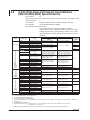
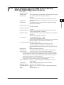
Measurement Interval, Integration Time, and Filter
The table below shows the available measurement intervals. The module is equipped
with an integrating A/D converter. The selectable integration time varies depending on
the measurement interval as shown in the table below. For details about the relationship
between noise and integration time, see section 2.7, “Measures against Noise on the
MX100” In addition, the type of noise rejection filter switches as shown in the table below.
Measurement Interval
10 ms
Integration Time
1.67 ms
16.67 ms
20 ms
Filter
Rejected Noise and Notes
600 Hz and its integer multiples*
60 Hz and its integer multiples
Rectangular
50 Hz and its integer multiples
50 ms
Automatically detects the power supply
Auto
frequency and set 16.67 or 20 ms
100, 200 ms
36.67 ms
Trapezoidal
50 Hz or 60 Hz and their integer multiples
500 ms
100 ms
Rectangular
10 Hz and its integer multiples
1, 2, 5,10, 20, 30, 60 s
200 ms
Cos
Fc = 5-Hz low-pass filter
* Since the power supply frequency noise is not rejected, the measured vales may fluctuate especially
with temperature measurement. In such cases, set the measurement interval to 50 ms or higher.
Measurement Synchronization
Each input channel has its own A/D converter. Therefore, measurements on each
channel are synchronized.
Common Mode Voltage
The common mode voltage between channels in a single module is 250 VACrms when
the signal is applied continuously.
The common mode voltage between modules and between a module and earth is 600
VACrms when the signal is applied continuously.
1-16
IM MX100-01E
1.4
1
This module is equipped with ten inputs and measures DC voltage, Thermocouple, threewire RTD, and digital input (DI) at a minimum measurement interval of 100 ms.
Explanation of Functions
Functions of the 10-CH, Medium-Speed
Universal Input Module
2
3
Terminal cover
4
Input terminal (clamp terminal)
5
Index
Input Type and Measurement Range
The following measurements are possible.
Input
DC voltage
Thermocouple
RTD
(Measurement current: 1 mA)
DI
IM MX100-01E
Measurement Range Type
20 mV
60 mV
200 mV
2V
6V
20 V
100 V
R
S
B
K
E
J
T
N
W
L
U
KPvsAu7Fe
Pt100
JPt100
Pt100 (high resolution)
JPt100 (high resolution)
Ni100 SAMA
Ni100 DIN
Ni120
Pt50
Cu10 GE
Cu10 L&N
Cu10 WEED
Cu10 BAILEY
J263B
Level
Contact input
Rated Measurement Range
–20.000 to 20.000 mV
–60.00 to 60.00 mV
–200.00 to 200.00 mV
–2.0000 to 2.0000 V
–6.000 to 6.000 V
–20.000 to 20.000 V
–100.00 to 100.00 V
0.0 to 1760.0°C
0.0 to 1820.0°C
–200.0 to 1370.0°C
–200.0 to 800.0°C
–200.0 to 1100.0°C
–200.0 to 400.0°C
0.0 to 1300.0°C
0.0 to 2315.0°C
–200.0 to 900.0°C
–200.0 to 400.0°C
0.0 to 300.0K
–200.0 to 600.0°C
–200.0 to 550.0°C
–140.00 to 150.00°C
–140.00 to 150.00°C
–200.0 to 250.0°C
–60.0 to 180.0°C
–70.0 to 200.0°C
–200.0 to 550.0°C
–200.0 to 300.0°C
–200.0 to 300.0°C
–200.0 to 300.0°C
–200.0 to 300.0°C
0.0 to 300.0K
Vth = 2.4 V
ON: 1 kΩ or less,
OFF: 100 kΩ or more
(parallel capacitance: 0.01 µF
or less)
1-17
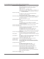
1.4 Functions of the 10-CH, Medium-Speed Universal Input Module
The following inputs can be used on MXLOGGER or the MX100/DARWIN API (sold
separately). These inputs cannot be used with the MX100 Standard Software.
Input
DC voltage
Thermocouple
RTD
(Measurement current: 1 mA)
Measurement Range Type
60 mV (high resolution)
1V
6 V (high resolution)
PLATINEL
PR40-20
NiNiMo
WRe3-25
W/WRe26
N (AWG14)
XK GOST
Cu10 at 20°C alpha = 0.00392
Cu10 at 20°C alpha = 0.00393
Cu25 at 0°C alpha = 0.00425
Cu53 at 0°C alpha = 0.00426035
Cu100 at 0°C alpha = 0.00425
Pt25 (JPt100 × 1/4)
Cu10 GE (high resolution)
Cu10 L&N (high resolution)
Cu10 WEED (high resolution)
Cu10 BAILEY (high resolution)
Pt100 GOST
Cu100 GOST
Cu50 GOST
Cu10 GOST
Rated Measurement Range
0.000 to 60.000 mV
–1.0000 to 1.0000 V
0.0000 to 6.0000 V
0.0 to 1400.0°C
0.0 to 1900.0°C
0.0 to 1310.0°C
0.0 to 2400.0°C
0.0 to 2400.0°C
0.0 to 1300.0°C
–200.0 to 600.0°C
–200.0 to 300.0°C
–200.0 to 300.0°C
–200.0 to 300.0°C
–50.0 to 150.0°C
–50.0 to 150.0°C
–200.0 to 550.0°C
–200.0 to 300.0°C
–200.0 to 300.0°C
–200.0 to 300.0°C
–200.0 to 300.0°C
–200.0 to 600.0°C
–200.0 to 200.0°C
–200.0 to 200.0°C
–200.0 to 200.0°C
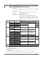
Measurement Interval, Integration Time, and Filter
The table below shows the available measurement intervals. The module is equipped
with an integrating A/D converter. The selectable integration time varies depending on
the measurement interval as shown in the table below. For details about the relationship
between noise and integration time, see section 2.7, “Measures against Noise on the
MX100” In addition, the type of noise rejection filter switches as shown in the table below.
Measurement
Interval
100 ms
200 ms
Integration
Time
1.67 ms
16.67 ms
20 ms
Burnout
Detection
Cycle
1 s*1
Filter
Rejected Noise and Notes
600 Hz and its integer multiples*2
60 Hz and its integer multiples
50 Hz and its integer multiples
500 ms
Automatically detects the power supply
Measurement
Auto
frequency and set 16.67 or 20 ms
interval
1s
36.67 ms
Trapezoidal
50 Hz or 60 Hz and their integer multiples
2s
100 ms
Rectangular
10 Hz and its integer multiples
5, 10, 20, 30, 60 s 200 ms
Cos
Fc = 5-Hz low-pass filter
*1 If the measurement interval is 100 ms, burnout detection is carried out on a single channel during
one measurement interval. Therefore, when starting measurement during the burnout condition or
thereafter, burnout can be detected for up to 10 measurements (approximately 1 second).
*2 Since the power supply frequency noise is not rejected, the measured vales may fluctuate especially
with temperature measurement. In such cases, set the measurement interval to 500 ms or higher, or
use the 4-CH, High-Speed Universal Input Module.
Rectangular
Measurement Synchronization
The module is equipped with a single A/D converter, and measurement is made
sequentially. Therefore, measurements of each channel are not synchronized.
Common Mode Voltage
The common mode voltage between channels in a single module is 120 VACrms when
the signal is applied continuously. The common mode voltage between modules and
between a module and earth is 600 VACrms when the signal is applied continuously.
1-18
IM MX100-01E
1.5
Functions of the 30-CH, Medium-Speed DCV/
TC/DI Input Module
1
MX110-VTD-L30
Explanation of Functions
This module is equipped with 30 inputs and measures DC voltage, Thermocouple, and
digital input (DI) at a minimum measurement interval of 500 ms.
It takes up three modules worth of space when attaching to the base plate.
2
3
MX110-VTD-L30/H3
4
Terminal
cover
5
Terminal
cover
Index
Input terminal
(clamp terminal)
Input terminal
(M3 screw terminal)
Input Type and Measurement Range
The following measurements are possible.
Input
DC voltage
Thermocouple
DI
IM MX100-01E
Measurement Range Type
20 mV
60 mV
200 mV
2V
6V
20 V
100 V
R
S
B
K
E
J
T
N
W
L
U
KPvsAu7Fe
Level
Contact input
Rated Measurement Range
–20.000 to 20.000 mV
–60.00 to 60.00 mV
–200.00 to 200.00 mV
–2.0000 to 2.0000 V
–6.000 to 6.000 V
–20.000 to 20.000 V
–100.00 to 100.00 V
0.0 to 1760.0°C
0.0 to 1820.0°C
–200.0 to 1370.0°C
–200.0 to 800.0°C
–200.0 to 1100.0°C
–200.0 to 400.0°C
0.0 to 1300.0°C
0.0 to 2315.0°C
–200.0 to 900.0°C
–200.0 to 400.0°C
0.0 to 300.0K
Vth = 2.4 V
ON: 1 kΩ or less,
OFF: 100 kΩ or more
(parallel capacitance: 0.01 µF
or less)
1-19
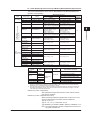
1.5 Functions of the 30-CH, Medium-Speed DCV/TC/DI Input Module
The following inputs can be used on MXLOGGER or the MX100/DARWIN API (sold
separately). These inputs cannot be used with the MX100 Standard Software.
Input
Measurement Range Type
60 mV (high resolution)
1V
6 V (high resolution)
PLATINEL
PR40-20
NiNiMo
WRe3-25
W/WRe26
N (AWG14)
XK GOST
DC voltage
Thermocouple
Rated Measurement Range
0.000 to 60.000 mV
–1.0000 to 1.0000 V
0.0000 to 6.0000 V
0.0 to 1400.0°C
0.0 to 1900.0°C
0.0 to 1310.0°C
0.0 to 2400.0°C
0.0 to 2400.0°C
0.0 to 1300.0°C
–200.0 to 600.0°C
Measurement Interval, Integration Time, and Filter
The table below shows the available measurement intervals. The module is equipped
with an integrating A/D converter. The selectable integration time varies depending on
the measurement interval as shown in the table below. For details about the relationship
between noise and integration time, see section 2.7, “Measures against Noise on the
MX100” In addition, the type of noise rejection filter switches as shown in the table below.
Measurement Interval
500 ms
Integration Time
1.67 ms
16.67 ms
20 ms
Filter
Rejected Noise and Notes
600 Hz and its integer multiples*
60 Hz and its integer multiples
Rectangular
50 Hz and its integer multiples
1s
Automatically detects the power supply
Auto
frequency and set 16.67 or 20 ms
2s
36.67 ms
Trapezoidal
50 Hz or 60 Hz and their integer multiples
5, 10, 20, 30, 60 s
100 ms
Rectangular
10 Hz and its integer multiples
* Since the power supply frequency noise is not rejected, the measured vales may fluctuate especially
with temperature measurement. In such cases, set the measurement interval to 1 s or higher, or use
the 4-CH, High-Speed Universal Input Module or the 10-CH, Medium-Speed Universal Input Module.
Measurement Synchronization
The module is equipped with a single A/D converter, and measurement is made
sequentially. Therefore, measurements of each channel are not synchronized.
Common Mode Voltage
The common mode voltage between channels in a single module is 120 VACrms when
the signal is applied continuously. The common mode voltage between modules and
between a module and earth is 600 VACrms when the signal is applied continuously.
1-20
IM MX100-01E
1.6
1
This module is equipped with six inputs and measures DC voltage, four-wire RTD, fourwire resistance, and digital input (DI) at a minimum measurement interval of 100 ms.
Explanation of Functions
Functions of the 6-CH, Medium-Speed FourWire RTD Resistance Input Module
2
3
Terminal cover
4
Input terminal (clamp terminal)
5
Index
Input Type and Measurement Range
The following measurements are possible.
Input
DC voltage
RTD*1
(Measurement current: 1 mA)
DI
Measurement Range Type
20 mV
60 mV
200 mV
2V
6V
20 V
100 V
Pt100
JPt100
Pt100 (high resolution)
JPt100 (high resolution)
Ni100 SAMA
Ni100 DIN
Ni120
Pt50
Cu10 GE
Cu10 L&N
Cu10 WEED
Cu10 BAILEY
J263B
Level
Contact input
Rated Measurement Range
–20.000 to 20.000 mV
–60.00 to 60.00 mV
–200.00 to 200.00 mV
–2.0000 to 2.0000 V
–6.000 to 6.000 V
–20.000 to 20.000 V
–100.00 to 100.00 V
–200.0 to 600.0°C
–200.0 to 550.0°C
–140.00 to 150.00°C
–140.00 to 150.00°C
–200.0 to 250.0°C
–60.0 to 180.0°C
–70.0 to 200.0°C
–200.0 to 550.0°C
–200.0 to 300.0°C
–200.0 to 300.0°C
–200.0 to 300.0°C
–200.0 to 300.0°C
0.0 to 300.0K
Vth = 2.4 V
ON: 1 kΩ or less,
OFF: 100 kΩ or more
(parallel capacitance: 0.01 µF
or less)
–200.0 to 600.0°C
–200.0 to 600.0°C
Pt500
RTD*1, *2
(Measurement current: 0.25 mA) Pt1000
20 Ω
0.000 to 20.000 Ω
(Measurement current: 1 mA)
200 Ω
0.00 to 200.00 Ω
Resistance*1
(Measurement current: 1 mA)
2 kΩ
0.0 to 2000.0 Ω
(Measurement current: 0.25 mA)
*1 RTD and resistance are all 4-wire measurements
*2 The Pt500 resistance table is Pt100 × 5, and the resistance table for Pt1000 is Pt100 × 10
IM MX100-01E
1-21
1.6 Functions of the 6-CH, Medium-Speed Four-Wire RTD Resistance Input Module
The following inputs can be used on MXLOGGER or the MX100/DARWIN API (sold
separately). These inputs cannot be used with the MX100 Standard Software.
Input
DC voltage
RTD
(Measurement current: 1 mA)
Measurement Range Type
60 mV (high resolution)
1V
6 V (high resolution)
Cu10 at 20°C alpha = 0.00392
Cu10 at 20°C alpha = 0.00393
Cu25 at 0°C alpha = 0.00425
Cu53 at 0°C alpha = 0.00426035
Cu100 at 0°C alpha = 0.00425
Pt25 (JPt100 × 1/4)
Cu10 GE (high resolution)
Cu10 L&N (high resolution)
Cu10 WEED (high resolution)
Cu10 BAILEY (high resolution)
Pt100 GOST
Cu100 GOST
Cu50 GOST
Cu10 GOST
Rated Measurement Range
0.000 to 60.000 mV
–1.0000 to 1.0000 V
0.0000 to 6.0000 V
–200.0 to 300.0°C
–200.0 to 300.0°C
–200.0 to 300.0°C
–50.0 to 150.0°C
–50.0 to 150.0°C
–200.0 to 550.0°C
–200.0 to 300.0°C
–200.0 to 300.0°C
–200.0 to 300.0°C
–200.0 to 300.0°C
–200.0 to 600.0°C
–200.0 to 200.0°C
–200.0 to 200.0°C
–200.0 to 200.0°C
Measurement Interval, Integration Time, and Filter
The table below shows the available measurement intervals. The module is equipped
with an integrating A/D converter. The selectable integration time varies depending on
the measurement interval as shown in the table below. For details about the relationship
between noise and integration time, see section 2.7, “Measures against Noise on the
MX100” In addition, the type of noise rejection filter switches as shown in the table below.
Measurement Interval
100, 200 ms
Integration Time
1.67 ms
16.67 ms
20 ms
Filter
Rejected Noise and Notes
600 Hz and its integer multiples*
60 Hz and its integer multiples
Rectangular
50 Hz and its integer multiples
500 ms
Automatically detects the power supply
Auto
frequency and set 16.67 or 20 ms
1s
36.67 ms
Trapezoidal
50 Hz or 60 Hz and their integer multiples
2s
100 ms
Rectangular
10 Hz and its integer multiples
5, 10, 20, 30, 60 s
200 ms
Cos
Fc = 5-Hz low-pass filter
* Since the power supply frequency noise is not rejected, the measured vales may fluctuate especially
with temperature measurement and 20 Ω measurement. In such cases, set the measurement interval
to 500 ms or higher.
Measurement Synchronization
The module is equipped with a single A/D converter, and measurement is made
sequentially. Therefore, measurements of each channel are not synchronized.
Common Mode Voltage
The common mode voltage between channels in a single module when applied
continuously is 120 VACrms, and the resistance for RTD is 50 VACrms.
The common mode voltage between modules and between a module and earth is 600
VACrms when the signal is applied continuously.
1-22
IM MX100-01E
1.7
1
This module is equipped with four inputs and measures strain from strain gauges and
from strain gauge type sensors at a minimum measurement interval of 100 ms.
-B12, -B35
-NDI
4
NDIS terminal
5
Input terminal
(clamp terminal)
Index
Measurement Range
Input
Strain
Measurement Range Type
2000 µ Strain
20000 µ Strain
200000 µ Strain
Rated Measurement Range
–2000.0 to +2000.0 µ Strain
–20000 to +20000 µ Strain
–200000 to +200000 µ Strain
Measurement Interval, Integration Time, and Filter
Measurement Interval
100 ms
Rejected Noise and Notes
600 Hz and its integer multiples*
60 Hz and its integer multiples
Rectangular
50 Hz and its integer multiples
200 ms
Automatically detects the power supply
Auto
frequency and set 16.67 or 20 ms
500 ms
36.67 ms
Trapezoidal
50 Hz or 60 Hz and their integer multiples
1s
100 ms
Rectangular
10 Hz and its integer multiples
2, 5,10, 20, 30, 60 s
200 ms
Cos
Fc = 5-Hz low-pass filter
* Since the power supply frequency noise is not rejected, the measured vales may fluctuate. In such
cases, set the measurement interval to 200 ms or higher.
Integration Time
1.67 ms
16.67 ms
20 ms
Filter
Measurement Synchronization
The module is equipped with a single A/D converter, and measurement is made
sequentially. Therefore, measurements of each channel are not synchronized.
Common Mode Voltage
For -B12 or -B35
The common mode voltage between channels in a single module when applied
continuously is 30 VACrms, or 250 VACrms between input and ground.
For -NDI
The common mode voltage between channels in a single module when applied
continuously is 30 VACrms, and 30 VACrms between input and ground (shell is nonisolated).
IM MX100-01E
2
3
Terminal cover
Explanation of Functions
Functions of the 4-CH, Medium-Speed Strain
Input Module (-B12, -B35, and -NDI)
1-23
1.7 Functions of the 4-CH, Medium-Speed Strain Input Module (-B12, -B35, and -NDI)
Initial Balancing (Initial Unbalance Value Adjustment)
When configuring a bridge circuit with a strain gauge, the bridge circuit will not
necessarily be balanced even if the strain of the circuit under test is zero due to the slight
deviation in resistance of the strain gauge, and the measured value may not be zero (the
value in such cases is called the initial unbalanced value.)
Therefore, when taking measurements you must first balance the bridge and, if the strain
is zero, obtain a measured value of zero. This is called initial balancing (setting the initial
unbalanced value to zero).
Measured value
Initial balance
Initial unbalanced value
0
Strain
Reset
With the MX100, initial balancing is performed in the ±10000 µ strain range.
Initial balance: The value when the command is executed is taken as the initial
unbalanced value, and the measured value is set to zero.
Reset: The value set during initial balancing is reset to zero. The initial
unbalanced value is used as-is for the measured value.
Note
If the measuring range is changed, the initial balancing is reset.
After a range change, you must redo initial balancing.
1-24
IM MX100-01E
1.7 Functions of the 4-CH, Medium-Speed Strain Input Module (-B12, -B35, and -NDI)
1
Scaling Settings When Using a Strain Gauge Type Sensor
2
The basic relational expression is as follows.
1 mV/V = 2000 µstrain (Equation 1)
Two examples are given below: 1) when rated input and output are listed in the user’s
manual of the strain gauge type sensor, and 2) when listed with the calibration coefficient.
(Hereinafter, “µstrain” will be expressed as “µStr.”)
When Rated Input and Rated Output Are Given
3
4
5
A specific example is given below.
• Rated input 200 N
(set to Y)
• Rated output 0.985 mV/V
(set to K)
Index
In this case, these figures indicate that if a 200 N load is applied, 0.985 mV/V is output.
From the relationship in equation 1, if 200 N is applied,
an output of 0.985 mV/V=0.985 × 2000=1970 µStr is attained.
In other words, for each 1 N, 1970 µStr/200 N= 9.85 µStr/N is output.
Therefore, the scaling settings are entered as follows.
When Measuring at 50-150 N
Scale minimum: 50 (set to Smin)
Scale maximum: 150 (units: N) (set to Smax)
therefore,
Span minimum: 50 × 9.85 µStr/N = 492.5 µStr
Span maximum: 150 × 9.85 =1477.5 µStr
can be set.
Thus, the measuring range is 2000 µStr.
Generally, the range is as follows.
Using the symbols that have appeared in the explanation thus far, after setting the scale
maximum and minimum, the values are as follows.
Span minimum = [(K(mV/V) × 2000) / Y(unit)] × Smin ([µ]Str)
Span maximum = [(K(mV/V) × 2000) / Y(unit)] × Smax ([µ]Str)
IM MX100-01E
Explanation of Functions
The following is an explanation of scaling settings used when measuring physical
quantities such as load and length with a strain gauge type sensor.
1-25
1.7 Functions of the 4-CH, Medium-Speed Strain Input Module (-B12, -B35, and -NDI)
When Listed at the Calibration Coefficient
An example is given with a displacement gauge.
• Rated input: 20 mm
• Calibration coefficient: 0.003998 mm / (1 µV/V)
Basically, if you can convert the calibration coefficient to the rated output mentioned in
“When Rated Input and Rated Output Are Listed,”the following is a calculation following
the explanation in “When Rated Input and Rated Output Are Listed.”
Using equation 1,
1 µV/V = 0.001 µV/V = 0.001 × 2000 µStr = 2 µStr
therefore the rated output with this sensor when 20 mm is input would be
20 mm ÷ [0.003998 mm/2 [µ]Str] = 10005 µStr
In other words, for each 1 mm, an output of
10005 µStr / 20 mm = 500.25 [µ]Str/mm
can be obtained.
Thereafter in the same manner, if you wish to measure with a scale of 2 mm to 15 mm,
the settings are:
Scale minimum: 2
Scale maximum: 15 (units: mm)
therefore,
Span minimum: 2 × 500.25 µStr/mm = 1000.5 µStr
Span maximum: 15 × 500.25 µStr/mm = 7503.75 µStr
would be appropriate settings.
The measuring range becomes 20000 µStr, making the resolution on the MX100 1 mStr,
therefore we can round as follows.
Span minimum: 1001 µStr
Span maximum: 7504 µStr
Compensation When the Gauge Factor Differs
If the gauge factor of the gauge being used differs from 2.00, it can be compensated
using the following method.
The relationship between the true strain (s) and the measured strain (si)
is:
εi = 2.00/Ks × εi
Ks: Gauge factor of the gauge used
Given this, set the following using the scaling function.
Measurement Span Scale
Minimum value Maximum value
Minimum value Maximum value
X
Y
2.00/Ks × X
2.00/Ks × Y
Ex.: for a gauge factor of 2.1,
1-26
Measurement Span Scale
Minimum value Maximum value
Minimum value
Maximum value
–1000.0
2000.0
–952.4
1904.8
IM MX100-01E
1.8
1
The -D05 module is equipped with ten inputs and measures non-voltage contact, open
collector, and 5-V logic inputs at a minimum measurement interval of 10 ms.
The -D24 module is equipped with ten inputs and measures 24 V logic inputs at a
minimum measurement interval of 10 ms.
Explanation of Functions
Functions of the 10-CH, High-Speed Digital
Input Module (-D05, -D24)
2
3
4
Terminal cover
5
Input terminal (clamp terminal)
Index
Measurement Interval
You can select a measurement interval of 10 ms, 50 ms, 100 ms, 200 ms, 500 ms, 1 s, 2 s,
5 s, 10 s, 20 s, 30 s, or 60 s.
Filters
The module detects ON/OFF as shown below to prevent receiving chattering effects. If
the measurement interval is set at a value greater than four times the chattering period,
measurement is possible in which chattering effects are avoided.
• Measurement interval of 5 s or less: Use the wider of the ON/OFF widths of the
detection period (approximately 75 to 90% of the measurement interval)
Measurement Measurement Measurement
interval
interval
interval
Detection
interval
Detection
interval
Detection
interval
Detection interval =
Measurement interval × 75% to 90%
Chattering
• Measurement interval of 5 s or more: Use the wider of the ON/OFF width of
approximately 4.5 s
IM MX100-01E
1-27
1.9
Functions of the 8-CH, Medium-Speed Analog
Output Module
This module is equipped with 8 outputs that can output voltage or current. An external
power source (24 V) is required for current output. For voltage output only, an external
power source is not required.
Terminal cover
Input terminal (clamp terminal)
Output Type
Transmission output:Outputs a voltage or current corresponding to the measured results
of the input channel specified on the same unit.
User output:
The specified value is output based on the value sent from the PC
software. Transmission output of computation channel data or of
data from separate units is available.
Output Range
Voltage: –10.000 V to 10.000 V
Current: 0.000 mA to 20.000 mA
Output Update Interval
The output is updated every 100 ms (minimum). It is not synchronized to the
measurement interval.
Operation When Errors Occur upon Startup
See section 1.11.
Output Operation During Calibration
Calibration Status
Output Status
Channels being calibrated
User output (output of calibration value)
Calibrated channels
Holds the last calibration user output value*
Non-calibrated channels
Holds the output value (holds the last output value during steady operation (see section 1.11))
* Holds the last calibration user output value until the next output update.
1-28
IM MX100-01E
1
This module is equipped with eight outputs that can output pulse wave duty. A duty pulse
waveform is output according to the specified pulse interval. A pulse interval can be set
for each channel.
Explanation of Functions
1.10 Functions of the 8-CH, Medium-Speed PWM
Output Module
2
3
4
Terminal cover
5
Input terminal (clamp terminal)
Index
Output Type
Transmission output:Outputs a duty pulse waveform corresponding to the measurement
computation results of the input channel specified on the same unit.
User output:
The specified value is output based on the data sent from the PC
software. Transmission output of computation channel data or of
data from separate units is possible.
Output Waveform
Output width
External
power supply
voltage
Duty=
Output width
×100 [%]
Pulse interval
Pulse interval
Pulse Interval
1 ms to 300 s (can be set channel by channel)
However,
1 ms interval setting rng: 1 ms to 30.000 s
10 ms interval setting rng: 10 ms to 300.00 s
Can be set in units of 1 ms
Can be set in units of 10 ms
Output Update Interval
The output is updated every 100 ms (minimum). It is not synchronized to the
measurement interval.
Output Range
0.000% to 100.000%
Operation When Errors Occur upon Startup
See section 1.11.
IM MX100-01E
1-29
1.11 Operation of the 8-CH Medium-Speed Analog
Output Module and the 8-CH Medium Speed
PWM Output Module
This section provides an explanation of the output operation of the analog output and
PWM output modules.
Output Selection When Errors Occur upon Startup
• Hold the previous value: Holds the last output value.
• Output the preset value: Outputs an arbitrarily specified output value.
Output Status
The voltage, current (analog output module), or pulse wave duty (PWM output module) is
output given the following output conditions.
• Transmission output: Outputs a analog or PWM corresponding to the measured
results of the input channel specified on the same unit.
The input modules that can be specified are all input modules
(excludes output modules).
• User output:
When a command is received from a PC software application
(MX100 Standard Software, MXLOGGER, or the MX100/
DARWIN API), analog or PWM output is performed according to
the received value.
After the power is turned ON and communications become available, “User Output”
is enabled. For transmission output within a unit, the output value is updated after
measurement begins.
Output on Disabled Channels
Types of Disabled Channels
Output
Channels disabled through setting changes Holds the last output value when
channels were active
Channels disabled upon startup
Output according to startup settings
The timing at which setting changes applied to the output module become active is as follows.
(Ex. When changing settings from transmission output within a unit to user output, the last value of
transmission output within a unit is held until the user output request is generated.)
Output Operation per Settings and Setting Changes
Status at Power ON and Output Operation
Status When Power Is Turned ON
Output Operation
When the output setting is disabled
Operation upon startup
For transmission output within units,
Before meas. start
Operation upon startup
referenced input channels disabled*
Measurement start
Operation upon errors
Transmission output within units
Before meas. start
Operation upon startup
Measurement start
Transmission output
Transmission output between units
Before meas. start
Operation upon startup
(User output)
Measurement start
User output
Manual output
No output request
Operation upon startup
(User output)
Output requested
User output
Pattern output
Before pattern output starts Operation upon startup
(User output)
Pattern output starts
User output
* Monitor “Off” on the PC software, and “Skip” on the MX100/DARWIN API.
1-30
IM MX100-01E
1.11 Operation of the 8-CH Medium-Speed Analog Output Module and the 8-CH Medium Speed PWM Output
Module
1
Output Operation per Setting Changes (Common)
Output Operation
Changes to settings for op. Hold prev. val. → preset val. Outputs a preset value the next
time upon startup the power is
turned ON
Preset val. → hold prev. val.
2
The last output value from the previous operation is held for the next time the power is turned ON (outputs the output value active when the power was last turned OFF during the previous session)
Changes to settings for op. Hold prev. val. → preset val. Outputs a preset value the next
time when error occurs an error
occurs
Preset val → hold prev. val.
Holds the last output value active before an error occurs even when the next error occurs.
Changes to the preset value setting*
No change (as above)
Output ch setting changed from Enabled → Disabled
Holds the output val. (last output val.)
* Changes are also applied to inactive channels.
Output Operation through Setting Changes (Individually by Output Setting)
Output Setting
Setting Changes (Contents)
Output Operation
Trans. output Range setting chng. AO: V↔ mA
Output value held
within units
(until next output event)
PWM: 1 ms ↔10 ms or interval
Op. setting chng.
Trans. within units → Trans. between units
Trans. within units → manual output
Trans. within units → pattern output
Trans. output Range setting chng. AO: V ↔ mA
Output value held
between units
(until next output event)
PWM: 1 ms ↔10 ms or interval
(user output) Op. setting chng.
Trans. between units → trans. within units
Trans. between units → manual output
Trans. between units → pattern output
Manual outputRange setting chng. AO: V ↔ mA
Output value held
(user output)
PWM: 1 ms ↔10 ms or interval
(until next output event)
Manual output → trans. within units
Op. setting chng.
Manual output → trans. between units
Manual output → pattern output
Span setting changes
Pattern output Range setting chng. AO: V ↔ mA
Output value held
(user output)
(until next output event)
PWM: 1 ms ↔10 ms or interval
Op. setting changes Pattern output → trans. within units
Pattern output → trans. between units
Pattern output → manual output
Span setting changes
If the PWM output module range setting is changed, the output value is not saved (the interval
changes)
IM MX100-01E
Explanation of Functions
Setting Changes (Contents)
1-31
3
4
5
Index
1.11 Operation of the 8-CH Medium-Speed Analog Output Module and the 8-CH Medium Speed PWM Output
Module
Steady Output Operation
Output Operation While Communication Is Connected
Communication Connection Status
Output Operation
Comm. connects (initial connection after power ON)
Operation upon startup
Comm. connects (disconnected and restored for the 2nd or more time)
Holds the output value (last output value)
Communication disconnected normally
Holds the output value (last output value)
Output Operation according to the Measurement Status and Transmission
Output Status
Transmission output in the table is ON when Transmission output is selected in the
Action menu of the MX100 Standard Software, or when DAQMXTRANSMIT_RUN is
executed in the MX100/DARWIN API. Transmission output in the table is OFF when
Transmission output is cleared in the Action menu of the MX100 Standard Software, or
when DAQMXTRANSMIT_STOP is executed in the MX100/DARWIN API.
Output Setting
Status
Trans. output
Meas stop → meas. start
within units
Starts trans. output/holds within
units output value (depends on
trans. output execution on/off )
on: transmission output starts
off: holds output value
Measuring → meas. stop
Holds output value (last output value)
Meas stopping Trans. output exec. on* → off* Holds output val. (no change.)
Trans. output exec on → off
Holds output val. (no change.)
Trans. output exec off → on
Starts trans. output
Trans. output exec on → off
Holds output val. (last val.)
Measuring
Trans. output
Meas stop → meas start
between units
(user output)
Starts user output or holds
output value (depends on trans
output exec. on/off status)
on: transmission output starts
off: output value held
Measuring → meas stop
Holds output value
(last output value)
Holds output val. (no change.)
Meas stopping Trans. output exec off → on
Trans. output exec on → off
Holds output val. (no change.)
Trans. output exec off → on
User output
Measuring
Trans. output exec on → off
Holds output val. (last output value)
Manual output
Meas stop → meas start
No effect
(user output)
Measuring → meas stop
No effect
Meas stopping Trans. output exec off → on
No effect
Trans. output exec on → off
No effect
Trans. output exec off → on
No effect
Trans. output exec on → off
No effect
Measuring
Pattern output
Meas stop → meas start
No effect
(user output)
Measuring → meas stop No effect
Meas stopping Trans. output exec off → on
No effect
Trans. output exec on → off
No effect
Trans. output exec off → on
No effect
Trans. output exec on → off
No effect
Measuring
* on: enabled off: disabled
Transmission output execute enabled:
Transmission output execute disabled:
1-32
Output Operation
when “Transmit” under the Action menu of the PC software is selected
when “Transmit” under the Action menu of the PC software is not selected
IM MX100-01E
1.11 Operation of the 8-CH Medium-Speed Analog Output Module and the 8-CH Medium Speed PWM Output
Module
1
Output When Abnormal, or after Recovery from Abnormality
Abnormal
Module
Abnrml
Display
*
Abnormal Status
Output Operation
Operation upon startup
Main Module
b[SQR] System error
bF
Dip switches
F0
ROM error
F1
SRAM error
F2
EEPROM error
F3
Battery error
F4
Ethernet error P[SQR]*
CF card related error
Explanation of Functions
Output Operation during Abnormality (by Module)
2
3
Operation upon startup
4
No effect (normal operation)
None
Communication timeout error Transmission within units: no effect (normal operation)
Transmission between units/manual output/pattern output: operation when error generated
C1
Comm multiple connect error
No effect (normal operation per the
previously connected device)
Output Modules E0
Range information error Operation upon startup or when
output value uncertain
E1
Calibration value error
E2
Error during calibration
E3
Internal communication error
occurs, resulting in an error recovery event. If the error recovery time is 10 s or more, output is performed per the operation upon error occurrence, and then output is executed per the operation upon startup.
Error in writing the calibration value.
E4
Unusable modules Operation upon startup or when output value uncertain
Input Modules
E0
Range information error
Operation upon errors occurrence
(except for transmission within
E1
Calibration value error
units, since the transmission
E4
Unusable modules source input channel is illegal)
E5
Initial balance error
No effect (±Over is likely)
* [SQR] is a placeholder for the number corresponding to the error.
IM MX100-01E
1-33
5
Index
1.11 Operation of the 8-CH Medium-Speed Analog Output Module and the 8-CH Medium Speed PWM Output
Module
Output Operation during Abnormality (by Output Setting)
Output Setting
Output Operation
Trans. output
Referenced input channels are +Over
within units
Outputs a value +5% of the specified
span of the output channel*2
Referenced input channels are –Over
Outputs a value –5% of the specified
span of the output channel*2
Referenced input channel is illegal
Operation upon errors
(input modules are removed)
Referenced input channel is disable*3
Referenced input channel is Invalid
(math error in difference computation)
Communication timeout No effect
Internal communication error
Output value held (immediately
after internal comm error occurs,
the output value is held, but there is
a recovery operation*1)
Operation upon errors
CPU abnormality
Trans. output
Referenced input channels are +Over
between units
(user output)
Outputs a value +5% of the specified
span of the output channel (calculated with MXSTANDARD, MXLOGGER, or the API)
Referenced input channels are –Over
Outputs a value –5% of the specified span of the output channel (calculated with MXSTANDARD, MXLOGGER, or the API)
Referenced input channel is illegal
(input modules are removed)
Operation upon errors (with MXSTANDARD,
Referenced input channel is disable*3
MXLOGGER, or the API)
Referenced input channel is Invalid
(math error occurs)
Communication timeout Operation upon errors
Internal communication error
Output value held (immediately after internal comm error occurs, the output value is held, but there is a recovery operation*1)
CPU abnormality
Operation upon errors
Manual output
Communication timeout Operation upon errors
(user output)
Internal communication error
Output value held (after internal comm
error occurs, the output value is held, but there is a recovery operation*1)
CPU abnormality
Operation upon errors
Pattern output
Communication timeout Operation upon errors
(user output)
Internal communication error
Output value held (immediately after internal comm error occurs, the output value is held, but there is a recovery operation*1)
Operation upon errors
*1
*2
*3
1-34
Abnormal Status
CPU abnormality
See “Output Operation after Recovery from Abnormality” on the next page.
However, only within the range that can be output.
Ex.: If the span for PWM is set to 0-100%, +Over is +100% and –Over is 0%.
Invalid with the MX100 Standard Software. With the API for MX100 and DARWIN, it is “Skip.”
IM MX100-01E
1.11 Operation of the 8-CH Medium-Speed Analog Output Module and the 8-CH Medium Speed PWM Output
Module
1
Output Operation after Recovery from Abnormality (by Output Setting)
Abnormality Recovery
Output Operation
Trans. output
within units
Referenced input module recovers
Operation upon errors → (removed input modules are inserted) transmission output
Referenced input channel changed from Skip to measurement range
Referenced input channel is Invalid
Recovers to normal from (math error in difference computation)
Recover after communication timeout No effect
2
3
Recover after internal comm error
If the error recovery time is 10 s or
more; operation upon error occurrence → operation upon
startup -> transmission output
If the error recovery time is within
10 s; operation upon startup →
transmission output
CPU abnormality (does not recover)
Operation upon errors
Trans. output
between units
Referenced input module recovers
Operation upon errors (per PC
(removed input modules are inserted) software → user output*1
(user output)
Referenced input channel changed
from Skip to measurement range.*2
Referenced channel is invalid; recovers
to normal value from (math error).
Recover after communication timeout Operation upon errors → user output*1
If the error recovery time is 10 s or more; operation upon error occurrence → operation upon
startup → user output*1
If the error recovery time is within 10 s, Operation upon startup →
user output*1
CPU abnormality (does not recover)
Operation upon errors
Manual output
Recover after communication timeout. Operation upon errors → user output*1
(user output)
Recover after internal comm error
If the error recovery time is 10 s or more, Operation upon errors → operation upon startup → user output*1
If the error recovery time is within 10 s, Operation upon startup → user output*1
CPU abnormality (does not recover)
Operation upon errors
Pattern output
Recover after communication timeout Operation upon errors → user output*1
(user output)
Recover after internal comm error
If the error recovery time is 10 s or
more; operation error occurrence →
operation upon startup → user output*1
If the error recovery time is within 10 s, Operation upon startup → user output*1
Operation upon errors
*1 Executes the user output from the PC software after recovery from errors.
*2 Invalid with the MX100 Standard Software. With the API for MX100 and DARWIN, it is “Skip.”
IM MX100-01E
4
5
Index
Recover after internal comm error
CPU abnormality (does not recover)
Explanation of Functions
Output Setting
1-35
1.12 Functions of the 10-CH, Medium-Speed Digital
Output Module
This module outputs ten contact signals based on the alarm output settings and output
settings on the PC software.
Terminal cover
Output terminal (clamp terminal)
Output Type
The MX100 has the following types (output factors) are available.
Type
Description
Relay Action
Output Hold
Behavior
Hold*2 or non-hold
selectable
Alarm output of measurement /
Energize or deenergize
computation channels
selectable
Manual DO operation using the
Energize or deenergize
Manual
software
selectable
When a failure occurs in the
Normal: Energized
Fail
CPU of the MX100 main module
Failure: Deenergized
Output when an error*1 is
Energize or deenergize Hold*2 or non-hold
Error
detected in the MX100
selectable
selectable
*1 Below are the errors that can occur in the MX100.
• A data output request timeout (60 s) occurs while recording data. (except when the /DS
option functions are enabled)
• An input module detected at power-on that is able to make measurements is removed.
• A module breaks down.
• An unidentifiable module is attached.
*2 Holds the output until the PC software issues the output release command (relay ACK).
Alarm
Output Update Interval
The output is updated every 100 ms (minimum). It is not synchronized to the
measurement interval.
Relay Action and Hold Behavior
You can select whether to energize or de-energize the output relay when outputting
contact signals on the PC software. You can also select whether the output relay is
turned OFF (non-hold) or kept ON (hold) until an output release command is received.
• When set to non-hold
Output cause
occurrence
• When set to hold
Output cause
occurrence
Relay ACK
1-36
Relay output ON
Relay output ON
Relay output OFF
Relay output OFF
IM MX100-01E
Chapter 2
2.1
Installation and Wiring
1
Handling Precautions
This section describes the precautions to be taken when using the MX100. Please read
this section carefully before use.
IM MX100-01E
2-1
Installation and Wiring
• If you are using this instrument for the first time, make sure to thoroughly read the
safety precautions given on pages ii and iii.
• Do not remove the case.
For internal inspection or adjustment, contact your nearest YOKOGAWA dealer.
• Do not place objects on top of the instrument.
Never place other instruments or objects containing water on top of the instrument.
Doing so can lead to malfunction.
• Take Proper Care When Carrying the Instrument
First, turn off the DUT and the MX100 and remove all cables including measurement
wires and communication cables. Then, remove the power cord from the outlet.
• To prevent internal overheating, do not obstruct the vent holes of the module.
• This instrument uses many plastic parts. When cleaning, wipe using a dry soft cloth.
Do not clean with benzine, thinner, or other chemicals, and do not use detergents.
Doing so can cause discoloring, deformation, or damage.
• Do not bring charged objects near the signal terminals. Doing so can lead to
malfunction.
• Do not pour volatile agents on the MX100 or leave it in contact with rubber or PVC
products for an extended time. Doing so can lead to malfunction.
• Do not apply shock to the instrument.
• When not in use, make sure to turn OFF the power.
• If there are any symptoms of trouble such as smoke, strange odors, or strange sounds
coming from the instrument, immediately turn OFF the power and stop the power
supply. Contact your dealer immediately.
• Do not damage the power cord.
Nothing should be placed on top of the power cord. The power cord should also be
kept away from any heat sources. When unplugging the power cord from the outlet,
never pull by the cord itself. Always hold and pull by the plug. If the cord is damaged,
contact your dealer for replacement. Refer to “Checking the Contents of the Package”
in the MX100 Data Acquisition Unit Operation Guide (IM MX100-02E) for the part
number of the appropriate power cord when placing an order.
2
3
4
5
Index
2.2
Installation
Installation Location
Install the instrument indoors in the following locations.
• Where the temperature is between 0 to 50°C.
Where the relative humidity is between 20 and 80% RH for 0 to 40°C and 10 and 50%
RH for 40 to 50°C. However, no condensation should be present.
Note
Condensation may occur if the instrument is moved to another place where the ambient
temperature is higher, or if the temperature changes rapidly. In addition, measurement errors
will occur when using thermocouple input. In this case, let the instrument adjust to the new
environment for at least an hour before using the instrument.
• Where the operating altitude is 2000 m or less.
• In a well-ventilated location
Install the instrument in a well-ventilated location to prevent the temperature inside the
instrument from rising.
• Where mechanical vibration is small
Select an installation location with a small amount of mechanical vibration (if any).
• In a horizontal location
Install the instrument on a flat, even surface.
Do not install the instrument in the following places.
• In dangerous locations where flammable liquid, vapor, or dust is present
• In direct sunlight or near heat appliances
Select a location with the smallest temperature fluctuation from room temperature (23
°C) as possible. Placing the instrument in direct sunlight or near heat appliances can
cause adverse effects.
• Where an excessive amount of soot, steam, humidity, dust, or corrosive gas is present
Soot, steam, humidity, dust, and corrosive gas can cause adverse effects on the instrument.
Avoid installing the instrument in an environment with a high level of such elements.
• Near magnetic field sources
Install the instrument in a location where the magnetic field is 400 A/m or less. Avoid
bringing instruments that produce magnetic fields or magnets near the instrument.
Using the instrument near a strong magnetic field source can cause measurement
errors.
Installation Procedure
CAUTION
When mounting the instrument on DIN rails, prevent the instrument from falling by
securing the DIN rails using a metal plate of 2 mm or more in thickness, fastened
with at least three screws.
The MX100 can be used on a desktop, on a floor, in a rack mount, or in a panel mount.
In all cases, be sure to install the instrument in a vertical position.
2-2
IM MX100-01E
2.2 Installation
Use on a Desktop or a Floor
Each module has feet that can be attached to the base plate allowing them to be placed
vertically. For the procedure for attaching the modules, see the next page.
1
2
Installation and Wiring
3
4
5
Functional ground terminal screw
Feet
Index
Attachment to a DIN Rail
As shown in the figure below, you can rack-mount or panel-mount the MX100 by
attaching a DIN rail mount bracket to the base plate.
• Attachment of the DIN rail mount bracket
to the base plate
• Attachment of the base plate to the DIN rail
Base plate
Base plate
Latch lever
(press to release
from the DIN rail)
Screw
holes
Attachment
screws (M3)
DIN rail mount
bracket
DIN rail mount bracket
DIN rail mount bracket
DIN rail*
* To prevent slacks in the DIN rail, fix at
least three locations of the DIN rail.
• Dimensions when mounted on a DIN rail
Unit: mm
442 (1 main module, for connecting six input/output modules)
92
DIN rail
131
31
158.6
442
384
326
268
/SL2
210
/SL2
152
/SL1
149.2
163
Module pitches 58
IM MX100-01E
2-3
2.3
Attaching the Modules
WARNING
To prevent electric shock and instrument breakdown, do not connect the power
supply to the main module when attaching modules.
Attachment Procedure
1. Check that the power supply is not connected to the main module.
2. Align the connector on the rear panel of the module to the module connector on
the base plate, and insert the connector.
Attach the main module to the right-most position on the base plate.
When the connectors are correctly connected, the guide pin on the rear panel of the module
is inserted into the guide hole on the base plate. In addition, the module is secured to the
base plate with the latch lever locking in place at the bottom section of the base plate.
3. Fasten the top of the module with the attachment screws (M3).
To remove the module, loosen the attachment screw, pull down on the
latch lever on the rear panel of the module, and pull the module straight
from the base plate.
Base plate
Module connector
Base plate connector
cover*
(accessory sold
separately)
* Can be attached by
hooking the top of the
cover to the top edge of
the base plate and
pressing down on the
bottom part.
Guide holes
Screw holes
Guide pins
Main module
Input/Output module
Module attachment screw
2-4
Latch lever
(pull down to remove the
module from the base plate)
Base plate
IM MX100-01E
2.3 Attaching the Modules
1
CAUTION
Main module (conventional model)
3
Main module
(reworked model)
Base plate
2
Installation and Wiring
When attaching the main module (conventional model) to the base plate, first
remove the two screws from the base plate and remove the BRACKET, then attach
the main module (conventional model) to the base plate.
Base plate
4
5
BRACKET
Pin protector stud
Index
Attachment Positions and Channel Numbers
The figure below shows how the channel numbers are identified on the PC.
Representation of channel numbers:
Channel numbers in a unit (001 to 060)
Unit number (00 to 19)*1
5
4
3
2
1
Slot number
0
MX100
041 to 050 021 to 030
001 to 010
051 to 060 031 to 040
011 to 020
*1 When connecting to the module
using the MX100 Standard
Software, the number is
fixed to 00.
Channel number in the unit*2
*2 The last one digit on a 4-channel module
is 1 to 4.
The last one digit on a 6-channel module
is 1 to 6.
The last one digit on a 8-channel module
is 1 to 8.
CAUTION
The 30-CH, Medium-Speed DCV/TC/DI Input Module takes up three modules
worth of space when attaching to the base plate. If attached incorrectly, damage or
malfunction can result.
IM MX100-01E
2-5
2.4
Connecting the Signal Wires
Terminal Arrangement Markings on the Terminal Cover
A character indicating the terminal function and a terminal symbol indicating the type of
signal to be input/output at each terminal are written on the back of the terminal cover of
each I/O module. For information on the wiring of each terminal signal, see “Connecting
the Signal Wires” (this section). The 4-CH, Medium-Speed Strain Module (-NDI) has no
terminal cover.
4-CH, High-Speed
Universal Input Module
Terminal
cover
100Vpk MAX TO
250V MAX CH TO CH
600V MAX TO
10-CH, Medium-Speed
Universal Input Module
100Vpk MAX + TO 120V MAX CH TO CH
600V MAX TO
CAT II
100Vpk MAX TO
120V MAX CH TO CH
600V MAX TO
1
2 CH6
3
4
5 CH7
6
7
8 CH8
9
10
11 CH9
12
13
14 CH10
15
Channel
number
within
module
Terminal
symbol
30-CH, Medium-Speed
6-CH, Medium-Speed
DCV/TC/DI Input Module 4-wire RTD Resistance
(/H3)
Input Module
Label for
screw
terminals
100Vpk MAX + TO 120V MAX CH TO CH
600V MAX TO
CAT II
1
CH6
2
3
4
CH7
1
CH1
2
3
4
5
CH3
6
7
CH9
8
7
CH4
8
9
CH10
10
9
CH5
10
11
11
10-CH, High-Speed
Digital Input Module
(-D05)
250V
1
2 CH6
3
4
5 CH7
6
7
8 CH8
9
10
11 CH9
12
13
14 CH10
15
Vext
CAT ll
1
2 CH1
3
4
5 CH2
6
7
8 CH3
9
10
11 CH4
12
13
14 CH5
15
8-CH, Medium-Speed
PWM Output Module
250V
Connect external power supply
to only one set of Vext terminals.
2-6
10Vpk MAX H TO L
30V MAX CH TO CH
250V MAX TO
10-CH, High-Speed
Digital Input Module
(-D24)
250V MAX TO
MAX TO
Vext
4-CH, Medium-Speed
Strain Input Module
(-B12, -B35)
50Vpk MAX + TO -
TO
MAX TO
8-CH, Medium-Speed
Analog Output Module
250V
100Vpk MAX TO
120V MAX CH TO CH(DCV-DI)
50V MAX CH TO CH(RTD-OHM)
600V MAX TO
1
2 CH1
3
4
5 CH2
6
7
8 CH3
9
10
11 CH4
12
13
14 CH5
15
Label for
clamp
terminals
CH2
5
CH8
6
10Vpk MAX
30-CH, Medium-Speed
DCV/TC/DI Input Module
250V MAX NO TO C
250V MAX CH TO CH
250V MAX TO
MAX TO
Vext
10-CH, Medium-Speed
Digital Output Module
Vext
Connect external power supply
to only one set of Vext terminals.
IM MX100-01E
2.4 Connecting the Signal Wires
1
Attaching and Removing the Terminal Block
The terminals of the input/output modules in the figure below can be removed. The
terminals of the 30-CH, Medium-Speed DCV/TC/DI Input Module (MX110-VTD-L30)
cannot be removed.
The terminal cover can be removed by pressing backward with the cover lifted up.
Installation and Wiring
4-CH, High-Speed Universal
Input Module
2
3
4-CH, Medium-Speed Strain
Input Module (-B12, -B35)
4
Pull-out
handle
5
The terminal block can
be attached and
detached.
The terminal plate can be
attached and detached.
Attachment screw
(Loosen before removing the terminal plate.)
10-CH, Medium-Speed Universal Input Module/
6-CH, Medium-Speed Four-wire RTD
8-CH, Medium-Speed Analog Output Module/
ResistanceInput Module/
8-CH, Medium-Speed PWM Output Module/
10-CH, High-Speed Digital Input Module
10-CH, Medium-Speed DigitalOutput Module
Pull-out
handle
The terminal plate can be
attached and detached.
Attachment screw
(Loosen before removing the terminal
plate.)
IM MX100-01E
The terminal block can be
attached and detached.
Attachment screw
(Loosen before removing the terminal block.)
2-7
Index
2.4 Connecting the Signal Wires
Attaching Plates with Screw Terminals and Plates with Clamped Terminals for
Current
You can attach a plate with screw terminals (sold separately, M3 screws) to the 10-CH,
Medium-Speed Universal Input Module and the 10-CH, High-Speed Digital Input Module.
You can also attach a plate with clamped terminals for current (sold separately) to the
10-CH, Medium-Speed Universal Input Module.
The plate is attached and removed in the same manner as terminal blocks. Note that the
terminal arrangement of the plate with screw terminals differs from that of the plate with
clamped terminals. The terminal arrangement is displayed on the back of the terminal
cover in the same package. Replace it along with the plate.
For handling of the plate with screw terminals, see the MX100/MW100 Handling of the
Plate with Screw Terminals (IM MX100-77E), and for the plate with clamped terminals for
current, see the MX100/MW100 Setting Up the Plate with Clamp Terminals for Current (IM
MX100-78E).
Plate with screw terminals
(model 772080)
Plate with clamp terminals for current
(model 772081 (10 Ω)/772082 (100 Ω)/772083 (250 Ω))
Attachment
screw
1
1
2
2
4
4
5
5
7
7
8
8
10
10
11
11
13
13
14
14
Attachment
screw
10
100mA
Screw Terminal Block
The 10-CH, Medium-Speed Universal Input modules and 10-CH, High-Speed Digital
Input modules allow you to remove the terminal plate and connect a 10-channel screw
terminal block (M4 screws, sold separately) that can be attached to a DIN rail (see the
figure below).
10-CH screw terminal block (772061)
CH 1
b
B
A
CH 2
CH 3
Attachment screw
for connector cover
CH 4
CH 5
CH 6
CH 7
Connector cover
CH 8
CH 9
CH 10
+/A
b
Terminal cover –/B
10-CH screw terminal
block (772061)
Loosen the attachment screw for the connector
cover and open the connector cover.
10-CH, Medium-Speed Universal Input Module/
10-CH, High-Speed Digital Input Module
Attachment to a DIN Rail
Attachment screw
Connection cable
between the input module
and screw terminal block
(772062-0XXX*)
* Length: 050 or 100 cm.
Attachment screw
2-8
DIN rail
Latch lever
(Pull down to detach.)
IM MX100-01E
2.4 Connecting the Signal Wires
1
General Precautions When Wiring the Input/Output Signal Wires
WARNING
2
Applied Voltage (Vrms or VDC)
30 (60 VDC)-100
101-150
151-300
301-600
Basic Insulation
620 V rms
840 V rms
1390 V rms
2210 V rms
3
4
Double (Reinforced) Insulation
1000 V rms
1400 V rms
2300 V rms
3700 V rms
• To avoid electric shock when removing the terminal block and terminal plate for
wiring, be sure to attach the terminal block and terminal plate to the input/output
module before inputting or outputting signals. Electric shock or fire can result if
signals are applied to the terminals when the terminal block is removed from the
input/output modules.
• When wiring to screw terminals, use insulation coated crimp-on lugs on the
terminals (4 mm screws on the screw terminal block, and 3 mm screws on the
screw terminals and screw terminal plate). Use round crimp-on lugs that do not
come out when loose.
• To prevent fire, use signal wires with a temperature rating in the table below or
higher.
Module Type
Screw terminal block
Universal input module, DCV/TC/DI input module,
four-wire RTD resistance input module, strain input module,
digital input module, and digital output module
Analog output module, PWM output module
Temp. Rating
75°C
80°C
85°C
CAUTION
• If a large pulling force is applied to the input/output signal wires connected to the
MX100, the terminal or signal wire may break. To prevent this from happening,
fix all the wiring cables to the installation panel.
• Wiring of the Strain Input Module (-NDI)
When connecting a bridge head, in order that the empty weight of the cable
does not exceed 5 kg, ensure that the cable does not hang down more than 1.5
m (the distance to the floor). If it does, secure the cable to the installation panel
or some other location.
• Do not apply a voltage exceeding the value indicated below to the input
terminals of the input module. The module may become damaged.
Module Type
Universal input
module
Max. Input Voltage
± 10 VDC: Voltage range of 1 VDC
or less, TC, RTD, and DI (contact)
± 120 VDC: Voltage range of 2
VDC or more, and DI (LEVEL)
IM MX100-01E
Installation and Wiring
• To prevent the possibility of electric shock when wiring, confirm that the power
supply source and signal source are turned OFF. After making the connections,
secure the terminal cover and do not touch the terminals with your hands.
• For signal wires on which voltage exceeding 30 VAC/60 VDC is applied relative
to the ground potential or between signals, use reinforced (double) insulation
wires. For all other signal wires, use basic insulation wires. For the withstand
voltage of insulation wires, see the table below.
Max. Common Mode Voltage
Between Channels Input to Ground
-H04:
600 VACrms
250 VACrms (50/60 Hz)
(50/60 Hz)
-M10:
120 VACrms
(50/60 Hz)
2-9
5
Index
2.4 Connecting the Signal Wires
Module Type
Max. Input Voltage
DCV/TC/DI input
module
± 10 VDC: Voltage range of 1 VDC
or less, TC, and DI (contact)
± 120 VDC: Voltage range of 2
VDC or more, and DI (LEVEL)
± 10 VDC: Voltage range of 1 VDC
or less, RTD, resistance, and DI
(contact)
Four-wire RTD
resistance input
module
± 120 VDC: Voltage range of 2
VDC or more, and DI (LEVEL)
Strain input
module
± 10 VDC
Digital input
module
-D05: ± 10 VDC
-D24: ± 50 VDC
Module Type
Analog/PWM
output module
Digital output
module
Max. Input Voltage
250 VAC or 250 VDC
Max. Common Mode Voltage
Between Channels Input to Ground
120 VACrms
600 VACrms
(50/60 Hz)
(50/60 Hz)
Voltage:
120 VACrms
(50/60 Hz)
RTD and
resistance:
50 VACrms
(50/60 Hz)
30 VACrms
(50/60 Hz)
-
600 VACrms
(50/60 Hz)
-B12 and -B35:
250 VACrms
(50/60Hz)
-NDI: 30 VACrms
(50/60Hz)
250 VACrms
(50/60 Hz)
Max. Common Mode Voltage
Between Channels Output to Ground
250 VACrms
(50/60 Hz)
250 VACrms
(50/60 Hz)
• The MX100 is a measurement category II (IEC61010-1) and installation
category II (CSA1N.61010-1) instrument.
Consider the points indicated below to prevent noise from entering the measurement
circuit. For a description of the measures against noise on the MX100, see section 2.7.
• Keep the measurement circuit away from the power supply cable (power supply
circuit) and ground circuit.
• It is desirable that the object under measurement is not a noise source. However, if
this is not avoidable, insulate the object under measurement and the measurement
circuit. In addition, ground the object under measurement.
• Shielded wires are effective against noise caused by electrostatic induction. As
necessary, connect the shield to the ground terminal of the MX100 (make sure this
does not lead to grounding at two points).
• Twisting the measurement circuit wires at short intervals is relatively effective against
noise caused by electromagnetic induction.
• Make sure to ground the protective ground terminal through a small grounding
resistance (less than or equal to 100 Ω).
When using the reference junction compensation of the MX100 through thermocouple
input, take measures to stabilize the temperature at the terminal section.
• Always close and secure the terminal cover.
• Do not use thick wires with high heat radiation effects (cross-sectional area of 0.5
mm2 or smaller recommended).
• Keep the ambient temperature consistent. Large temperature fluctuations occur in
such cases as when a fan nearby is turned ON/OFF.
Connecting the input wires in parallel with other instruments may mutually affect
the measured values.
If you need to make a parallel connection:
• Turn OFF burnout.
• Ground each instrument at a single common point.
• Do not turn ON/OFF the instrument while measurement is in progress. It may cause
adverse affects on the other instrument.
Note that RTDs and resistors cannot be connected in parallel.
2-10
IM MX100-01E
2.4 Connecting the Signal Wires
1
Wiring Procedure
1. Turn OFF the power to the MX100.
2
2. Loosen the terminal cover attachment screw and lift up the terminal cover.
Installation and Wiring
3. Connect the signal wires to the terminals.
4. Return the terminal cover to the original position and secure it with the screw.
3
The appropriate screw tightening torque is 0.6 N·m.
For 4-CH, High-Speed Universal Input Module
4
Attachment screw for terminal cover
Terminal cover
5
Index
Input terminal (clamp terminal)
Wiring the Universal Input Module and DCV/TC/DI Input Module
• Thermocouple input
A
A
B
B
b
• RTD input
Compensation
lead
B
A
b
b
Lead wire resistance per wire of
10 Ω or less*. Make the resistance
of the three wires equal.
* In the case of Pt100 Ω.
5 Ω max for Pt50 Ω. 1 Ω max. for Cu10 Ω.
• DC voltage input/DI input (contact)
+
A
or
–
DC voltage Contact
input
B
b
• DC current input
A
B
b
+
DC current input
–
Shunt resistor
Example: For 4 to 20 mA input,
shunt resistance values should
be 250 Ω ±0.1%.
A plate with clamp terminals for current with built-in
shunt resistance can be attached to the 10-CH,
Medium-Speed Universal Input Module.
Terminal type:
Clamp, or screw (in the case of M3: -L30/H3)
Applicable wire size: For -H04, 0.2 to 2.5mm2 (AWG24 to 12)
For -M10 and -L30 (clamp), 0.14 to 1.5mm2 (AWG26 to 16)
Note
• On the 10-CH, Medium-Speed Universal Input module, RTD input terminals A and B are
isolated on each channel. Terminal b is shorted internally across all channels.
• Measurement using RTDs cannot be performed with the 30-CH, Medium-Speed DCV/TC/DI
Input Module.
• When the screw terminal plate (model 772080) is connected to the 10-CH, Medium-Speed
Universal Input Module, the terminal arrangement differs from that of clamped terminals, so
wire according to the markings on the terminal cover.
IM MX100-01E
2-11
2.4 Connecting the Signal Wires
Wiring the Four-Wire RTD Resistance Input Modules
• DC voltage input/DI (contact) input
Voltage
I
B
A
B
DC voltage Contact
Input
Nothing connected to the
I or C terminal
C
Resistance, RTD
I
+
A
• RTD input, resistance input
C
Resistance per lead wire of 10 Ω or less
• DC current input
I
+
DC current input
–
Shunt resistor
Example: For 4 to 20 mA input,
shunt resistance values should
be 250 Ω ±0.1%.
A
B
C
Terminal type:
Clamp
Applicable wire size: 0.14 to 1.5mm2 (AWG26 to 16)
Wiring the Strain Input Modules
Note
When using a sensor without a remote sensing wire, use the DV450-001 (conversion cable).
• One-Gauge Method
R
R: fixed resistance
r: resistance value of lead
wire
Rg: resistance value of strain
gauge
e: output voltage from bridge
E: voltage applied to bridge
R
e
R
Rg
Rg
E
-NDI
-B12, -B35
Setting switch
No.1
No.2
No.3
No.4
No.5
OFF
A(+V)
Rg
Bridge head
(701955 or 701956)
Rg
B( L)
C(-V)
D( H)
ON
No.1 No.2 No.3 No.4 No.5
ON ON ON OFF OFF
Setting switch
ON
1
2
3
4
5
6
7
8
OFF
SW
1 2 3 4 5
SW1 SW2 SW3 SW4 SW5
ON ON ON ON OFF
2-12
IM MX100-01E
2.4 Connecting the Signal Wires
1
• One-Gauge Three-Wire Method
R
r
Rg
R
R
r
2
e
Installation and Wiring
r
3
E
R: fixed resistance
r: resistance value of lead wire
Rg: resistance value of strain gauge
e: output voltage from bridge
E: voltage applied to bridge
-NDI
1
2
3
4
5
6
7
8
Rg
-B12, -B35
Setting switch
No.1
No.2
No.3
No.4
No.5
A(+V)
Rg
B(L)
Setting switch
ON
C(-V)
5
Index
OFF
D( H)
ON
OFF
4
Bridge head
(701955 or 701956)
SW
No.1 No.2 No.3 No.4 No.5
ON ON OFF ON OFF
1 2 3 4 5
SW1 SW2 SW3 SW4 SW5
OFF ON ON ON OFF
• Adjacent Two-Gauge Method
R
R
Rg1
e
R: fixed resistance
r: resistance value of lead
wire
Rg: resistance value of strain
gauge
e: output voltage from bridge
E: voltage applied to bridge
Rg2
Rg2
Rg1
E
-NDI
-B12, -B35
Setting switch
No.1
No.2
No.3
No.4
No.5
OFF
Rg2
C(-V)
ON
Rg1
A(+V)
Rg1
Bridge head
(701955 or 701956)
B(L)
Rg2
D( H)
No.1 No.2 No.3 No.4 No.5
ON ON OFF OFF ON
Setting switch
ON
1
2
3
4
5
6
7
8
OFF
SW
1 2 3 4 5
SW1 SW2 SW3 SW4 SW5
OFF ON ON ON OFF
IM MX100-01E
2-13
2.4 Connecting the Signal Wires
• Opposing Two-Gauge Method
R
Rg1
Rg2
R: fixed resistance
r: resistance value of lead wire
Rg: resistance value of strain
gauge
e: output voltage from bridge
E: voltage applied to bridge
e
R
Rg1
Rg2
E
-NDI
Bridge head
(701955 or 701956)
-B12, -B35
Setting switch
No.1
No.2
No.3
No.4
No.5
1
2
3
4
5
6
7
8
Rg1
A(+V)
Rg1
B( L)
C(-V)
Rg2
D( H)
ON
OFF
Rg2
Setting switch
No.1 No.2 No.3 No.4 No.5
ON OFF ON OFF ON
ON
OFF
SW
1 2 3 4 5
SW1 SW2 SW3 SW4 SW5
ON OFF ON ON OFF
• Opposing Two-Gauge Three-Wire Method
r
Rg1
R
r
r
r
r
Rg2
Rg1
e
R
Rg2
r
E
-B12, -B35
Cannot be connected. Use -NDI.
-NDI
R: fixed resistance
r: resistance value of lead wire
Rg: resistance value of strain gauge
e: output voltage from bridge
E: voltage applied to bridge
Bridge head
(701955 or 701956)
1
2
3
4
5
6
7
8
Rg1
Rg2
Setting switch
ON
OFF
SW
1 2 3 4 5
SW1 SW2 SW3 SW4 SW5
OFF OFF OFF ON OFF
2-14
IM MX100-01E
2.4 Connecting the Signal Wires
1
• Four-Gauge Method
Rg4
Rg3
R: fixed resistance
r: resistance value of lead wire
Rg: resistance value of strain gauge
e: output voltage from bridge
E: voltage applied to bridge
e
Rg2
2
Installation and Wiring
Rg1
3
E
Rg1, Rg3
4
Rg1
Rg2, Rg4
Rg2
5
Rg1
Rg3
Rg3
Rg4
Rg1, Rg2
Rg3, Rg4
Index
-B12, -B35
Setting switch
No.1
No.2
No.3
No.4
No.5
OFF
A(+V)
Rg1
B( L)
Rg2
C(-V)
Rg3
D( H)
Rg4
ON
No.1 No.2 No.3 No.4 No.5
OFF OFF OFF OFF ON
Bridge head
(701955 or 701956)
-NDI
1
2
3
4
5
6
7
8
Rg1
Rg4
Rg2
Rg3
Setting switch
ON
OFF
SW
1 2 3 4 5
SW1 SW2 SW3 SW4 SW5
OFF OFF OFF ON OFF
IM MX100-01E
2-15
2.4 Connecting the Signal Wires
Wiring the Digital Input Modules (-D05, -D24)
Note
• With the digital input module, the (–) terminal and unassigned terminals on all channels are
shorted internally.
• When the screw terminal plate (model 772080) is connected to the digital input module, the
terminal arrangement differs from that of clamp terminals, therefore wire according to the
markings on the terminal cover.
Wiring with the -D05 Option
• Contact input
• Transistor input
• 5V logic input
Main Input Specifications (-D05)
Input type:
Input format:
DI (non-voltage contact, open collector, and 5 V logic)
Pull-up at approximately 5 V/approximately 5 kΩ, common
electric potential between channels
Min. detection pulse width:
Twice the sampling interval or more
Input threshold level:
Non-voltage contact, open collector: ON at 100 Ω or less and
OFF at 100 kΩ or greater
5-V logic: OFF at 1 V or less and ON at 3 V or greater
Contact/transistor rating:
Contact with a rating of 15 VDC or greater and 30 mA or
greater
Vce and Ic are transistors with ratings of 15 VDC or more, and
30 mA or more, respectively.
Terminal type:
Clamp
Applicable wire size: 0.14 to 1.5 mm2 (AWG26 to 16)
Wiring with the -D24 Option
• 24 V logic input
24V
Main Input Specifications (-D24)
Input type:
DI (24 V logic)
Input format:
Common potential between ch
Min. detection pulse width:
Twice the sampling interval or more
Input threshold level: 24 V logic: OFF at 6 V or less and ON at 16 V or greater
Terminal type:
Clamp
Applicable wire size: 0.14 to 1.5 mm2 (AWG26 to 16)
2-16
IM MX100-01E
2.4 Connecting the Signal Wires
1
Wiring the Analog Output Modules
External power supply
+ 24 V
power supply
Vext
Voltage
Current
V+
(when using current output)
I+
Load Direction of
current
3
CAUTION
4
Two power supply terminals are connected internally. Therefore, do not connect a
separate external power supply to them as fire can result.
5
Main Output Specifications
Terminal type:
Load impedance: Applicable wire size: Index
Clamp, attached and removed in units of 4 channels
Voltage 5 kΩ or more
Current 600 Ω or less
0.08 to 2.5 mm2 (AWG28 to 12)
Wiring the PWM Output Modules
External power supply
+
4-28 V
power supply
Pulse width output
V+
Load
CAUTION
Two power supply terminals are connected internally. Therefore, do not connect a
separate external power supply to them as fire can result.
Main Output Specifications
Output capacity:
1A/ch max, however, 4 A or less total for all modules*1, *2
Terminal type:
Clamp, attached and removed in units of 4 channels
Applicable wire size: 0.08 to 2.5 mm2 (AWG28 to 12)
*1 A 1A current limit circuit is built in to the output circuit. Once the current limit circuit is ON,
the circuit continues to operate unless the external power supply is turned OFF.
*2 This module has a built-in fuse. The built-in fuse protects against fires or abnormal
emissions of heat due to load short-circuiting or other abnormalities.
IM MX100-01E
2
Installation and Wiring
Load
2-17
2.4 Connecting the Signal Wires
Wiring the Digital Output Modules
NO
C
250 VDC/0.1 A, 250 VAC/2 A, or
30 VDC/2 A (resistance load)
Main Output Specifications
Contact mode:
Contact capacity:
Terminal type:
Applicable wire size:
A contact (SPST)
250 VDC/0.1 A, 250 VAC/2 A, or 30 VDC/2 A (resistance load)
Clamp, attached and removed in units of 5 channels
0.08 to 2.5 mm2 (AWG28 to 12)
Note
Do not connect anything to the unassigned terminals of the digital output module.
2-18
IM MX100-01E
2.5
Power Connection and ON/OFF
2
WARNING
Installation and Wiring
1
• To prevent the possibility of electric shock when wiring, confirm that the power
supply source is turned OFF.
• To prevent an electric shock or fire, use only power cords supplied by
YOKOGAWA for the MX100.
• Make sure to perform protective earth grounding to prevent electric shock.
Connect the power cord for the MX100 to a three-prong power outlet with a
protective earth terminal. The AC outlet must be of a three-prong type with a
protective earth ground terminal.
Do not use the functional ground terminal (see section 2.2, “Installation”) as a
protective earth terminal.
• Do not use an extension cord without protective earth ground. Otherwise, the
protection function will be compromised.
3
4
5
Index
Use a power supply that meets the conditions indicated below.
Item
Rated supply voltage
Supply voltage range used
Rated supply voltage frequency
Allowable line frequency range
Maximum power consumption
Specification
100-240 VAC rms
AC power supply, 90 to 250 VAC rms
50/60 Hz
50/60 Hz ±2%
Up to approximately 70 VA maximum when six modules are used
Note
Do not use a supply voltage in the range 132 to 180 VAC, as this may have adverse effects on
the measurement accuracy.
Connections with the Power Cord (Power Supply/Cord Basic Specification Code
1*)
* is D, F, R, Q, or H.
1. Check that the power switch of the main module is OFF.
2. Connect the power cord plug to the power connector of the MX100. (Use the
power cord that came with the package.)
3. Connect the plug on the other end of the power cord to the outlet that meets the
conditions above.
Use a three-prong power outlet with a protective earth ground terminal.
3-prong outlet
Power switch
Power cord
(included in the package)
IM MX100-01E
Power
connector
When the basic suffix code is 1D
2-19
2.5 Power Connection and ON/OFF
Wiring the Power Supply Terminal (Power Supply/Cord Basic Specification Code 1W)
WARNING
• Set up a switch on the power supply line that shuts off the main power supply to
the instrument. Also, include an ON/OFF indicator with the switch as well as a
label that identifies the switch as the power shut down switch.
Switch specifications
Steady state current rating: 3 A or more
Inrush current rating: 80 A or more
Conforms with IEC60947-1 and -3
• Connect a fuse of 2 A to 15 A to the power supply line.
• Do not insert a switch or fuse on the ground line.
1. Check that the power switches to the power supply and main module are turned
OFF.
2. Loosen the power terminal cover attachment screws on the main module and
open the terminal cover.
3. Wire the power supply cord and protective grounding cord to the power supply
terminal as shown in the figure below.
Use round crimp-on lugs with isolation sleeves (for 4 mm screws) for the power cord and
protective ground cord terminals.
4. Close the power supply terminal cover and secure it with the screw.
Power supply terminal cover
L N
Power cord
Protective grounding cord
Protective grounding cord
crimp-on lugs
with isolation
sleeves
2-20
Power cord
IM MX100-01E
2.5 Power Connection and ON/OFF
1
Turning ON/OFF the Power Switch
displayed as “
.”
Note
• Before turning the power ON, check that the modules are attached correctly and that the
power cord is connected correctly.
• If the 7-segment LED does not illuminate when the power switch is turned ON, turn OFF
the power switch and check the points listed below. If the condition does not change when
turning ON the power even after checking those items, it is probably a malfunction. Contact
your nearest YOKOGAWA dealer for repairs.
• That the power cord is plugged in properly.
• That the power supply voltage is within the “supply voltage range used” indicated in this
section.
• If the 7-segment LED displays something other than a unit number when the power switch is
turned ON, see section 3.1, “Error Display on the 7-Segment LED and Corrective Actions.”
and carry out the specified corrective action. If the displayed information does not change
even when you carry out the corrective action, it is probably a malfunction. Contact your
nearest YOKOGAWA dealer for repairs.
IM MX100-01E
2-21
2
Installation and Wiring
Pressing the “I” side of the power switch turns the instrument ON. Pressing the “O” side
turns the instrument OFF.
When turned ON, the 7-segment LED (see section 1.2, “Main Module Functions”)
illuminates. When the instrument is ready (after completing the self-test), the unit number
is displayed. When using the MX100 Standard Software, the unit number is fixed at 00
3
4
5
Index
2.6
Connecting the Ethernet Cable
Connection Procedure
Connectors
Connect the Ethernet cable to the Ethernet port (10BASE-T/100BASE-TX) of the main
module. Use a UTP cable (category 5 or better) or an STP cable for the Ethernet cable.
Ethernet port
RJ-45 modular jack
Ethernet cable
Connection to the PC
Make the connection via a hub. For one-to-one connection with a PC, connect as shown
in the figure below. Likewise, up to twenty MX100s can be connected to a single PC.
However, to connect two or more MX100s, MXLOGGER (sold separately) must be used
instead of the MX100 Standard Software that comes with the instrument.
PC
Hub
LAN cable
(straight cable)
MX100
MX100
Ethernet port
Note
• The NIC on the PC should support 100BASE-TX (recommended) or 10BASE-T.
• When connected to an external network, the communications within the network other than
those related to the MX100 may hinder the measurement operations on the MX100.
• The MX100 can be connected to an auto-negotiating hub (between 10BASE-T and
100BASE-TX), but connection may fail on some hubs due to the hub not recognizing the
signal output from the MX100. If this happens, you can turn only dip switch 6 of the main
module OFF to fix the data rate to 10 Mbps. Operate the dip switch only when the power is
turned OFF.
2-22
IM MX100-01E
2.6 Connecting the Ethernet Cable
1
Checking the Communication Status
You can check the status on the two LEDs at the upper-right and lower-right of the
Ethernet port.
ETHERNET
2
Installation and Wiring
LINK LED
Illuminates in orange when the link between
the MX100 and the connected device is
established and communication is mutually possible.
3
ACT LED
Blinks green when transmitting/receiving packets.
10BASE - T
100BASE - TX
4
Initializing the Settings
5
The dip switch on the main module is used to initialize the settings including the IP
address assigned to the MX100.
Index
1. Turn OFF the power to the MX100.
2. Turn dip switch 5 of the main module OFF.
3. Turn ON the power to the MX100.
The 7-segment LED indicates the self-test operation at power up (see section 1.2, “Main
Module Functions”), and then displays bF.
4. Check the status of step 3, then turn the power OFF.
5. Turn dip switch 5 back ON.
DATA ACQUISITION UNIT
ETHERNET
SW
ON
1 2 3 4 5 6 7 8
POWER
10BASE - T
100BASE - TX
100 - 240V AC
70VA MAX
50/60Hz
Do not operate without reading safety precaution in users manual.
Check that the settings have been initialized (using the MX100 Standard Software, for
example).
7-segment LED
Dipswitches
• Normal setting
ON
Open the cover during
operation.
Power switch
1
3
4
5
6
7
8
• Turn switch 5 OFF
ON
1
IM MX100-01E
2
2
3
4
5
6
7
8
2-23
2.7
Measures against Noise on the MX100
Technical Information described below on measures against noise is available
as reference material. For information on obtaining a copy, contact your nearest
YOKOGAWA dealer.
• Noise Interference on Recorder (TI 4D5B1-80E)
Describes the fundamentals concerning noise and its countermeasures in two parts:
basic edition and application edition.
• MX100 Performance Specifications (TI 04M08B01-00E)
Describes in detail the functions related to noise rejection specific to the MX100.
This section briefly describes the integrating A/D converter and the first-order lag filter
that the MX100 employs as measures against noise.
Integrating A/D Converter
MX100 input modules employ an integrating A/D converter for converting the measured
analog signals into digital signals. The integrating A/D converter integrates the measured
values at the specified time width. If the specified time width matches the period of the
signal you wish to reject, the signal is rejected.
Cancelled out
Input voltage
(instantaneous value)
DC voltage (average value)
Integration time
For example, if the integration time is 20 ms, signals having frequencies of 50 Hz and
integer multiples of 50 Hz can be rejected. Likewise, if the integration time is 16.67 ms,
signals having frequencies of 60 Hz and integer multiples of 60 Hz can be rejected. If
the integration time is 100 ms, signals having 10 Hz and integer multiples of 10 Hz can
be rejected. The commercial power supply is one of the noise sources. By setting these
integration times, commercial power noise of 50 Hz or 60 Hz can be eliminated.
2-24
IM MX100-01E
2.7 Measures against Noise on the MX100
On the MX100, the integral time is determined by the measurement interval setting as
shown in the table below.
1
4-CH, High-Speed Universal Input Module
2
50 ms
Integration
Time
1.67 ms
16.67 ms
20 ms
Filter
Rectangular
Auto
Rejected Noise and Notes
600 Hz and its integer multiples*
60 Hz and its integer multiples
50 Hz and its integer multiples
Automatically detects the power supply frequency
and set 16.67 or 20 ms
50 Hz or 60 Hz and their integer multiples
10 Hz and its integer multiples
100, 200 ms
36.67 ms
Trapezoidal
500 ms
100 ms
Rectangular
1, 2, 5,10, 20,
200 ms
Cos
Fc = 5-Hz low-pass filter
30, 60 s
* Since the power supply frequency noise is not rejected, the measured vales may fluctuate
especially with temperature measurement. In such cases, set the measurement interval to 50
ms or higher.
10-CH, Middle-Speed Universal Input Module/6-CH, Medium-Speed Four-Wire RTD
Resistance Input Module
Measurement
Interval
100, 200 ms
Integration
Time
1.67 ms
16.67 ms
20 ms
Filter
Rejected Noise and Notes
600 Hz and its integer multiples*
60 Hz and its integer multiples
Rectangular
50 Hz and its integer multiples
500 ms
Automatically detects the power supply frequency
Auto
and set 16.67 or 20 ms
1s
36.67 ms
Trapezoidal
50 Hz or 60 Hz and their integer multiples
2s
100 ms
Rectangular
10 Hz and its integer multiples
5, 10, 20, 30, 60 s 200 ms
Cos
Fc = 5-Hz low-pass filter
* Since the power supply frequency noise is not rejected, the measured vales may fluctuate
especially with temperature measurement. In such cases, set the measurement interval to 500
ms or higher, or use the 4-CH, High-Speed Universal Input Module
30-CH, Middle-Speed DCV/TC/DI Input Module
Measurement
Interval
500 ms
Integration
Time
1.67 ms
16.67 ms
20 ms
Filter
Rejected Noise and Notes
600 Hz and its integer multiples*
60 Hz and its integer multiples
Rectangular
50 Hz and its integer multiples
1s
Automatically detects the power supply frequency
Auto
and set 16.67 or 20 ms
2s
36.67 ms
Trapezoidal
50 Hz or 60 Hz and their integer multiples
5, 10, 20, 30, 60 s 100 ms
Rectangular
10 Hz and its integer multiples
* Since the power supply frequency noise is not rejected, the measured vales may fluctuate
especially with temperature measurement. In such cases, set the measurement interval to 1 s
or higher, or use the 4-CH, High-Speed Universal Input Module or the 10-CH, Medium-Speed
Universal Input Module.
4-CH, Medium-Speed Strain Input Module
Measurement
Interval
100 ms
200 ms
Integration
Time
1.67 ms
16.67 ms
20 ms
Auto
Filter
Rectangular
Rejected Noise and Notes
600 Hz and its integer multiples*
60 Hz and its integer multiples
50 Hz and its integer multiples
Automatically detects the power supply frequency
and set 16.67 or 20 ms
50 Hz or 60 Hz and their integer multiples
10 Hz and its integer multiples
500 ms
36.67 ms
Trapezoidal
1s
100 ms
Rectangular
2, 5,10, 20,
200 ms
Cos
Fc = 5-Hz low-pass filter
30, 60 s
* Since the power supply frequency noise is not rejected, the measured vales may fluctuate. In
such cases, set the measurement interval to 200 ms or higher.
IM MX100-01E
2-25
Installation and Wiring
Measurement
Interval
10 ms
3
4
5
Index
2.7 Measures against Noise on the MX100
First-Order Lag Filter
For noise sources other than power supply noise, the MX100 is equipped with a firstorder lag filter having output characteristics indicated in the figure below against step
input. The time constant of the first-order lag filter can be selected on the PC software
(MX100 Standard Software, MXLOGGER (sold separately), or the API for the MX100/
DARWIN (sold separately)).
100%
Step input
Output characteristics
63.2% of the output value
0%
Time constant
Measurement
Interval (s)
0.01
0.05
0.1
0.2
0.5
1
2
5
10
20
30
60
n=5
0.05
0.25
0.5
1
2.5
5
10
25
50
100
150
300
n=10
0.1
0.5
1
2
5
10
20
50
100
200
300
600
Selectable Time Constants (s)
n=20
n=25
n=40
0.2
0.25
0.4
1
1.25
2
2
2.5
4
4
5
8
10
12.5
20
20
25
40
40
50
80
100
125
200
200
250
400
400
500
800
600
750
1200
1200
1500
2400
n=50
0.5
2.5
5
10
25
50
100
250
500
1000
1500
3000
n=100
1
5
10
20
50
100
200
500
1000
2000
3000
6000
If the first-order lag filter is applied to the input signal, low-pass filter frequency
characteristics shown in the figure below are attained.
Cutoff frequency
Attenuation Pass band Cutoff band
0dB
–3dB
Frequency
If the time constant of the first-order lag filter is set long, the cutoff frequency is lowered,
and frequency bandwidth that can be rejected is widened. Set an appropriate time
constant according to the frequency of the noise you wish to reject.
2-26
IM MX100-01E
2.8
Handling of the CF Card
1
Handling Precautions of the CF Card
Inserting the CF Card
To insert the CF card into the card slot, open the slot cover and face the card’s front side
to the right.
2
Installation and Wiring
Note the following points when using the CF card. For the general handling precautions
of the CF card, see the user's manual that came with the card.
• The CF card is a precision electronic device. Do not use or store the CF card in an
environment with strong static electricity or an environment where electric noise tends
to appear.
• Do not remove the CF card from the card slot while data is being written. Doing so can
damage or erase the data.
3
4
5
Index
Slot cover
Card slot
Front side of
the CF card
Ejecting the CF Card
Be sure to check that the CF card is not being accessed before ejecting the card from
the slot. When the CF card is being accessed, the 7-segment LED indicates this fact (see
section 1.2, “Contents Displayed on the 7-Segment LED”).
To eject the CF card, open the slot cover while touching the metal for discharging the
static electricity, and press the eject lever once. Then, press the eject lever that came out
once again, and remove the CF card from the slot.
Access stop switch
Slot cover
Eject lever
Metal for discharging the static electricity
Note
• If it is difficult to press the eject lever with your finger, use an object with a narrow tip such
as a pen as shown in the figure above.
• Do not close the slot cover by force when the eject lever is out. Doing so can damage the
CF card slot. When not using the eject lever, push the lever in so that the slot cover can be
closed.
• If you need to eject the CF card while it is being accessed (when the operation mode is
backup), open the slot cover and press the access stop switch (see the figure above) at
the top section of the slot. After the data save operation to the CF card stops (the displayed
operation mode on the 7-segment LED described under “Contents Displayed on the
7-Segment LED” in section 1.2 changes from backup to measurement), eject the CF card.
IM MX100-01E
2-27
Chapter 3
Troubleshooting and Maintenance
3.1
1
Error Display on the 7-Segment LED and
Corrective Actions
SW
ON
1 2 3 4 5 6 7 8
POWER
10BASE - T
100BASE - TX
100 - 240V AC
70VA MAX
50/60Hz
2
3
Troubleshooting and Maintenance
DATA ACQUISITION UNIT
ETHERNET
Do not operate without reading safety precaution in users manual.
The main module has a two-digit 7-segment LED as shown in the figure below. The
7-segment LED displays the system status. This section describes the displays on the
7-segment LED when errors occur on the system and their corrective actions. For normal
displays other than errors, see “Contents Displayed on the 7-Segment LED” in section 1.2.
7-segment LED
4
5
Index
If servicing is necessary, or if the instrument is not operating correctly after performing
the corrective actions below, contact your nearest YOKOGAWA dealer.
Errors at Power ON
The left and right digits of the 7-segment LED display “b” and an error code, respectively.
The LED illuminates.
Probable Cause
The display is b* (where * is any character
other than F). The dip switch settings are not
correct.
The display is bF.
The dip switch settings are not correct.
Corrective Action
Turn OFF the power, eject the CF card, turn ON all dip switches,
and start up again. If the situation does not change servicing is
required.
Powering up in setup reset mode. Turn OFF the power, turn ON
all dip switches, and power up again. Since all settings such as
the IP address are initialized, reconfiguration is necessary.
Ref. Page
2-27
2-23
System Errors
The left and right digits of the 7-segment LED display “F” and an error code, respectively.
The LED illuminates.
Display
F0
F1
F2
F3
Probable Cause
System ROM error.
SRAM error
EEPROM error
Error in the internal battery of the
main module.
F4
F5
Ethernet controller error
Internal data error
(only when the /DS option is enabled)
IM MX100-01E
Corrective Action
Servicing required.
Servicing required.
Servicing required.
Servicing required.
However, this error is also displayed immediately after the battery
is replaced. If this happens, power-cycle the MX100.
Servicing required.
Servicing required.
Ref. Page
-
-
3-1
3.1 Error Display on the 7-Segment LED and Corrective Actions
Module Errors
The left and right digits of the 7-segment LED display “E” and an error code,
respectively. The LED illuminates. In the case of module errors, the error number and the
corresponding module number are displayed alternately as shown in the figure below.
Error number
Module number
Display Probable Cause
E0
Range information error.
E1
Calibration value error.
Ref. Page
*
E2
*
E3
E4
E5
*
Corrective Action
Servicing required.
Check the module’s installation status, then recalibrate the
module.
If the error occurs even after recalibrating, servicing is required.
Calibration reference voltage value is Check whether the correct calibration reference voltage is being
not correct (during calibration).
applied or whether the channel to which the voltage is applied is
correct.
Error in writing the calibration value.
Servicing required.
The installed module cannot be used. Replace the module with one that can be used.
Initial balancing Error
Check the module’s installation status, then perform initial
(Initial unbalance value adjustment)
balancing again.
If the error occurs even after recalibrating, servicing is required.
See the MX100 Standard Software User’s Manual (IM MX180-01E).
-
Media-Related Errors
The left and right digits of the 7-segment LED display “P” and an error code, respectively.
The LED blinks. The error code is saved to the log file (see “Log File Storage” under
“Saving Data to the CF Card” in section 1.2).
Display Probable Cause
P0
Manipulated the CF card while it was
being accessed.
P1
CF card error.
P2
P3
P4
P5
*
Corrective Action
Do not manipulate the CF card while it is being accessed.
The CF card may not be formatted or may be damaged. Check
the CF card.
The CF card was not formatted
Insert the CF card into the CF card slot and format the card again,
correctly.
or replace with another CF card.
Not enough free space on the CF
Delete unneeded data to increase the free space, or replace with
card.
another CF card.
The number of files saved on the CF
Delete unneeded files to decrease the number of files, or replace
card exceeded 512.
with another CF card.
Overwrite error in the data storage
The time needed to store the file must be reduced. Delete
buffer.
unneeded data to increase the free space, or format the CF card.
If you are using a software application through the MX100/
DARWIN API, the timeout setting may not be appropriate. If so,
change the value to an appropriate value.
See the MX100 Standard Software User’s Manual (IM MX180-01E).
Ref. Page
2-27
*
*
*
*
Communication Errors
The left and right digits of the 7-segment LED display “C” and an error code, respectively.
The LED blinks.
Display Probable Cause
C1
Multiple connection error.
*
3-2
Corrective Action
Disconnect the current connection and reconnect. However, this
error may also appear when the Ethernet cable is removed and
inserted again. Turn OFF the power and reconnect.
See the MX100 Standard Software User’s Manual (IM MX180-01E).
Ref. Page
*
IM MX100-01E
3.2
1
Troubleshooting
2
If servicing is necessary, or if the instrument is not operating correctly after performing
the corrective actions below, contact your nearest YOKOGAWA dealer for repairs.
The 7-segment LED does not illuminate.
Corrective Action
Turn ON the power switch.
Check whether the power supply voltage is within the rated range.
Servicing required.
Servicing required.
Ref. Page
2-21
2-19
-
Corrective Action
Remove the input/output module one by one and determine the
broken module (servicing required.)
Replace the main module.
(Servicing required.)
Ref. Page
2-4
The 7-segment LED blinks repeatedly.
Probable Cause
The power supply is shorted inside the input/
output module.
The power supply is shorted inside the main
module.
The LINK LED does not turn ON.
There is a problem with the PC.
The ACT LED does not turn ON.
There is a problem in the connection
between the hub and the MX100.
The ACT LED does not turn ON.
There is a problem with the PC.
There is a problem in the network
configuration.
The settings are not correct.
There is a problem in the network
configuration.
The setting changes have not taken effect.
There is a problem in the software created
using the MX100/DARWIN API.
The PC and the MX100 are not in the same
segment.
Corrective Action
Replace the Ethernet cable.
Ref. Page
2-22, 2-23
Check the hub’s power supply. If it still does not work, replace the
hub and check the hub’s operation. Also, try to connect the MX100
using the 10-Mbps fixed mode.
Check whether the PC can connect to the network.
Replace the PC’s NIC.
Check the hub’s power supply. If it still does not work, replace the
hub and check the hub’s operation.
Also, try to connect the MX100 using the 10-Mbps fixed mode.
Check whether the PC can connect to the network.
Replace the PC’s NIC.
Check that the IP address, subnet mask, and default gateway
settings of the PC correspond to the MX100 settings.
2-22, 2-23
2-22, 2-23
2-22, 2-23
2-22, 2-23
*
Turn OFF the power to the PC and the MX100, and carry out
reconnection.
2-21, *
Check whether the connection can be made using the MX100
Standard Software.
Connect the PC and the MX100 in the same network segment.
When connected as shown in the following figure, the Search
button cannot be used to detect the MX100, but you can make the
connection by manually specifying the IP address of the MX100.
*
*
MX
Network A
Router
Network B
PC
*
When using Windows XP, Windows Vista, or Windows 7, check
the firewall function.
See the MX100 Standard Software User’s Manual (IM MX180-01E).
IM MX100-01E
4
5
Index
2-4
The MX100 cannot be detected from the PC or cannot be detected with the Search button.
Probable Cause
The LINK LED does not turn ON.
The cable is broken.
The LINK LED does not turn ON.
There is a problem with the hub.
3
Troubleshooting and Maintenance
Probable Cause
The power switch is not ON.
The supply voltage is too low.
The fuse is blown.
The power supply is broken.
3-3
3.2 Troubleshooting
The MX100 can be detected using the Search button, but connection fails.
Probable Cause
The IP address is set to the default value.
The default value cannot be used to make the
connection.
There is a problem in the network
configuration.
The PC software, main module style number,
and release number rule is not upheld.
*
Corrective Action
Set the correct IP address.
Check that the IP address, subnet mask, and default gateway
settings of the PC and the MX100 settings are correct.
Check the PC software release number and main module style
number before upgrading the version.
[PC software release no.] ≥ [main module style no.]
See the MX100 Standard Software User’s Manual (IM MX180-01E).
Ref. Page
*
*
i
The Calibrator cannot connect to the MX100.
Probable Cause
Attempting to make multiple connections.
Another software program such as the MX100
Standard Software is already connected.
The main module and input/output module
style number rule is not upheld.
*
Corrective Action
Close all other software programs such as the MX100 Standard
Software.
Check the release number of the PC software and the main
module style number, then upgrade the version.
[PC software release no.] ≥ [main module style no.] ≥ [input/output
module style no.]
See the MX100 Standard Software User’s Manual (IM MX180-01E).
Ref. Page
*
i
The connected input/output module is not detected.
Probable Cause
Module connection or module startup error.
Attached the module while the power was ON.
The PC software, main module, and input/
output module style and release number rule
is not upheld.
Corrective Action
Turn OFF the power. Detach the input/output module once and
attach it again.
Check the PC software release number and main module style
number before upgrading the version.
[PC software release no.] ≥ [main module style no.] ≥ [input/output
module style no.]
Carried out an incorrect calibration.
Recalibrate.
The 10-CH, Pulse Input Module (MX114The 10-CH, Pulse Input Module cannot be used with the MX100.
PLS-M10) is connected.
Use this module with the MW100.
* See the MX100 Standard Software User’s Manual (IM MX180-01E).
3-4
Ref. Page
2-4, 2-19
i
*
1-5
IM MX100-01E
3.2 Troubleshooting
The measured value is not correct.
Ref. Page
2-11 to 2-18
*
*
*
Corrective Action
Make the alarm and output relay settings appropriate.
Both the alarm and output relay must be set appropriately.
See the MX100 Standard Software User’s Manual (IM MX180-01E).
*
4
-
5
2-11
2-24
-
Index
2-12 to 2-15
2-12 to 2-15
4-23
-
Ref. Page
*
The CF card is not detected.
Probable Cause
There is a problem with the CF card.
IM MX100-01E
Corrective Action
Replace the CF card.
Eject and format the CF card, then insert it again.
2
3
Alarms are not output.
Probable Cause
There is a problem in the alarm setting.
1
Troubleshooting and Maintenance
Probable Cause
Corrective Action
The input wiring is not correct.
Check the input wiring.
The measured value indicates +Over or Over. Change to an appropriate setting.
The measurement range setting and input
range do not match.
The temperature error is large or is unstable.
Change to the correct setting.
The TC type setting and the type actually
connected are different.
The temperature error is large or is unstable.
Change to the correct setting.
The RJC setting is not correct.
The temperature error is large or is unstable.
Block the wind from hitting the terminals.
The wind is hitting the terminals.
The temperature error is large or is unstable.
Suppress changes in the ambient temperature such as by placing
The ambient temperature change is drastic. the MX100 in a box.
The temperature error is large or is unstable.
Match the thickness and length of the three input wires.
There is an error in the wiring resistance (in
the case of an RTD).
The measurement error is large or is unstable. Take measures against noise effects.
The measurement error is large or is unstable. Reduce the signal source resistance such as by inserting a
Effects from the signal source resistance.
converter.
The temperature error is large or is unstable.
Stop parallel connections.
Effects from parallel connections.
Do not use the burnout setting.
Measured values from the strain gauge type
When using a sensor without a remote sensing wire, use the
sensor are not correct.
DV450-001 (conversion cable).
On the strain module (-B12, -B35), the gauge
Enter the correct settings.
method and dip switch settings are not correct.
On the strain module (-B12, -B35), the gauge
Use a module that supports the resistance value of the strain
resistance and internal bridge resistance
gauge (For 120 Ω, -B12, and for 350 Ω, -B35).
values are different.
On the strain module, scaling is not set
Displayed with 1 gauge method conversion. Set scaling
appropriately according to the gauge method. appropriately according to the gauge.
(for 2 gauge, 4 gauge methods, the amount of
strain is doubled or quadrupled.)
On the strain module (-NDI), a strain gauge
When using a sensor without a remote sensing wire, use the
type sensor without a remote sensing wire is
DV450-001 (conversion cable).
being used.
* See the MX100 Standard Software User’s Manual (IM MX180-01E).
Ref. Page
2-27
3-5
3.3
Calibration
It is recommended that the MX100 be calibrated once a year to assure its measurement
accuracy. A calibration instrument with an appropriate accuracy and resolution is required
for calibrating the MX100.
Range Calibration of DC Voltage, RTD, Resistance, Strain, and Analog Output
Required Instruments
•
•
•
•
DC voltage/current standard
Must meet the following specifications (M/9100 by FLUKE or equivalent)
Output range: 20 mV to 100 V
Accuracy in the output range: ±(0.01% + 1 µV) or less
Resistance standard
Must meet the following specifications (ADR3204 by Alpha Electronics or equivalent)
Resistance setting range (resolution): 0.2 to 1999 Ω (0.001 Ω), 0.2 to 19999 Ω (0.01 Ω)
Resistance accuracy of the resistance setting range: ±(0.01% of rdg + 2 mΩ) or less
* For calibrating the Universal Input Module and 6-CH Medium-Speed, Four-Wire
Resistance Input module
Bridge head (Yokogawa Electric model 701955 and 701956)
Digital multimeter
Must meet the following specifications (7562 by Yokogawa Electric or equivalent)
Accuracy: ±0.01% or less
Calibration Procedure
1. Wire the module being calibrated and the calibration instrument as shown in
the figure below, and adequately warm up the MX100 (the warm-up time of the
MX100 is at least 30 minutes).
2. Check that the operating environment such as ambient temperature and humidity
is within the standard operating conditions (see sections 4.4 through 4.8).
3. Connect the PC and the MX100 so that communication is possible. Start the
Calibrator of the MX100 Standard Software, and then start the calibration.
For the operating procedure of the Calibrator, see the MX100 Standard Software User’s
Manual (IM MX180-01E).
Wiring Diagram
• When calibrating the DC voltage range of the 4-CH, High-Speed Universal Input
module
When calibrating 0 V
100Vpk MAX TO
250V MAX CH TO CH
600V MAX TO
When calibrating a range other than 0 V
100Vpk MAX TO
250V MAX CH TO CH
600V MAX TO
* Carry out calibration for each input terminal.
Input terminal
+
Short
–
Input terminal
+
Hi
–
Lo
DC voltage/current standard
3-6
IM MX100-01E
3.3 Calibration
1
• When calibrating the RTD range of the 4-CH, High-Speed Universal Input module
When calibrating 0 Ω
When calibrating a range other than 0 Ω
100Vpk MAX TO
250V MAX CH TO CH
600V MAX TO
2
100Vpk MAX TO
250V MAX CH TO CH
600V MAX TO
3
* Carry out calibration for each input
terminal.
Input terminal
A
B
Make the resistance of
three lead wires equal.
Input terminal
A
B
Short
4
b
b
5
H
L
G
Index
Resistance standard
• When calibrating the DC voltage range of the 10-CH, Medium-Speed Universal Input
module
100Vpk MAX TO
120V MAX CH TO CH
600V MAX TO
Short the input terminal of CH1 (apply 0 V)
+
+ –
–
Hi
Lo
Input terminal of CH2
DC voltage/current standard
• When calibrating the RTD range of the 10-CH, Medium-Speed Universal Input module
100Vpk MAX TO
120V MAX CH TO CH
600V MAX TO
Short the input terminal of CH3 (connect 0 Ω)
A
B
b
A
B
b
Make the resistance of three lead wires equal.
When calibrating the RTD (1 mA) 600 mV range,
connect 300 Ω to the input terminal of CH5.*
* When calibrating the RTD (1 mA) 60 mV range, connect 60 Ω to
the input terminal of CH6.
When calibrating the RTD (1 mA) 200 mV range, connect 200 Ω
to the input terminal of CH4.
H
L
G
Resistance standard
IM MX100-01E
Troubleshooting and Maintenance
3-7
3.3 Calibration
• When calibrating the DC voltage range of the 30-CH, Medium-Speed DCV/TC/DI
Input module
For MX110-VTD-L30
100Vpk MAX + TO 120V MAX CH TO CH
600V MAX TO
CAT II
1
2 CH6
3
4
5 CH7
6
7
8 CH8
9
10
11 CH9
12
13
14 CH10
15
1
2 CH1
3
4
5 CH2
6
7
8 CH3
9
10
11 CH4
12
13
14 CH5
15
Short the input terminal of CH1 (apply 0 V)
Cable 80°C
1
2
3
4
5
6
7
8
9
10
11
12
13
14
15
1
2
3
4
5
6
7
8
9
10
11
12
13
14
15
+
–
+
–
Hi
Lo
DC voltage/current standard
Input terminal of CH2
For MX110-VTD-L30/H3
100Vpk MAX + TO 120V MAX CH TO CH
600V MAX TO
CAT II
1
2
3
4
5
6
CH6
CH7
1
2
3
4
CH1
CH2
CH8
5
6
7
8
CH9
7
8
CH4
9
10
CH10
9
10
CH5
11
CH3
Short the input terminal of CH1 (apply 0 V)
11
Cable 80°C
+
–
+
–
Hi
Lo
DC voltage/current standard
Input terminal of CH2
• When calibrating the DC voltage range of the 6-CH, Medium-Speed Four-Wire RTD
Input module
100Vpk MAX + TO 120V MAX CH TO CH(DCV-DI)
50V MAX CH TO CH(RTD-OHM)
600V MAX TO
CAT II
1
2
3 CH4
4
5
6
7
B 8 CH5
C 9
10
I 11
+ A 12
- 13 CH6
B
C 14
15
I
+A
-
B
C
I
+A
-
1
2
3 CH1
4
5
6
7
B 8 CH2
C 9
10
I 11
+ A 12
- 13 CH3
B
C 14
15
I
+A
-
B
C
I
+A
-
Short the input terminal of CH1 (apply 0 V)
+
–
+
–
Input terminal of CH2
3-8
Hi
Lo
DC voltage/current standard
IM MX100-01E
3.3 Calibration
• When calibrating the RTD or resistance range of the 6-CH, Medium-Speed Four-Wire
RTD Resistance Input module
1
2
3
Short the input terminal
of CH3 (connect 0 Ω)
4
I
A
B
C
Resistance standard
5
When calibrating the RTD (1 mA)
20 mV range, connect 20 Ω to the
input terminal of CH4.*
* When calibrating the RTD (1 mA) 60 mV range, connect 60 Ω to the input terminal of CH5.
When calibrating the RTD (1 mA) 200 mV range, connect 200 Ω to the input terminal of CH6.
When calibrating the RTD (1 mA) 600 mV range, connect 300 Ω to the input terminal of CH4.
When calibrating the RTD (0.25 mA) 600 mV range, connect 2400 Ω to the input terminal of CH5.
When calibrating the RTD (0.25 mA) 1 V range, connect 3000 Ω to the input terminal of CH6.
• When calibrating the range of the 4-CH, Medium-Speed Strain Module (-B12, -B35,
and -NDI)
The clamp terminal (-B12, -B35) and NDIS terminal (-NDI) are connected with the
4-gauge method (see below and next page). Resistors R1-R3 use 120 Ω, and a
resistance corresponding to the Zero or Full value is connected to R4.
To correctly calibrate the range, do so in the order Zero, then Full.
Res. R4
Resistance value
accuracy
Zero
Full*
2000 µstrain
120.000 Ω
120.000 Ω 117.154 Ω
±0.005%, ±0.3ppm/°C
20000 µstrain
120.000 Ω
120.000 Ω 113.010 Ω
±0.005%, ±0.3ppm/°C
200000 µstrain
120.000 Ω
120.000 Ω
80.000 Ω
±0.005%, ±0.3ppm/°C
* The Full calibration value of 2000 µstrain range is approximately to 12000 µstrain
The Full calibration value of 20000 µstrain range is approximately to 30000 µstrain
The Full calibration value of 200000 µstrain range is approximately 200000 µstrain
Calibration Range
Res. R1, R2, and R3
For -B12, -B35
1
2
Setting switch (CH1 to CH4)
3
4
No.1
No.2
No.3
No.4
No.5
OFF
R2
R1
R4
R3
A(+)
5
B(L)
6
C(-V)
7
D(H)
8
Connect CH2
only
9
ON
No.1 No.2 No.3 No.4 No.5
OFF OFF OFF OFF ON
10
11
12
13
14
15
16
IM MX100-01E
Troubleshooting and Maintenance
I
A
B
C
3-9
Index
3.3 Calibration
Bridge head
(701955 or 701956)
For -NDI
1
2
3
4
5
6
7
8
R2
R1
R4
R3
Connect CH2 only
Switch the
bridge head
ON
OFF
SW
1 2 3 4 5
SW1 SW2 SW3 SW4 SW5
OFF OFF OFF ON OFF
• When calibrating the output range of the 8-CH, Medium-Speed Analog Output module
All channels are calibrated at Zero (0 V) and Full (10 V).
1
2
H
L
3
4
5
Digital multimeter
YOKOGAWA 7562
6
7
8
9
10
11
12
13
14
15
3-10
IM MX100-01E
3.3 Calibration
1
Calibration of Temperature Measurements using Thermocouples
Required Instruments
•
•
DC voltage/current standard
Must meet the following specifications (5520A by FLUKE or equivalent)
Output accuracy: ±(0.005% + 1 µV) or less
0°C standard temperature device
Must meet the following specifications (ZC-114/ZA-10 by Coper Electronics or
equivalent)
Standard temperature stability accuracy: ±0.05°C or less
2
3
The input terminal section of the input modules is normally near room temperature, so
that the actual thermocouple output differs from the 0°C reference thermoelectromotive
table value. Modules able to measure temperature with thermocouples can be
compensated by measuring the temperature of the input terminal and adding the
corresponding thermoelectromotive force to the actual thermocouple output. Therefore
with the measurement terminal shorted (equivalent to an edge detection of 0°C), the
measured value indicates the temperature of the input terminal.
When calibrating modules capable of temperature measurements using thermocouples,
it is necessary to apply input from a DC standard voltage current generator with this
compensation voltage subtracted (the electromotive force of the 0°C standard that is
equivalent to the temperature of the input terminal). As in the figure, when performing
reference junction compensation at 0°C using a 0°C standard temperature device, you
can perform the calibration by inputting the 0°C standard electromotive force from a DC
standard voltage/current generator.
Wiring Diagram
Thermocouple wires or
4-CH, High-Speed Universal
Copper wires TC extension wires
Input Module*
100Vpk MAX TO
250V MAX CH TO CH
600V MAX TO
Input terminal
+
–
+
-
Copper
wires
DC voltage standard
Thermocouple
wires
Cold junction
0°C standard temperature
device
Note
* Connect the 10-CH, Medium-Speed
Universal Input Module and the
30CH, Medium Speed DCV/TV/DI
Input Module in the same manner
as well.
• Unlike the range calibration of DC voltage or RTD, the input section cannot be adjusted
for calibration of temperature measurement on the MX100 using a thermocouple. If
accuracy specifications are not upheld after calibration of temperature measurement using
thermocouples (see sections 4.4 through 4.6), check for input error and other factors, then
contact your Yokogawa dealer.
• If errors exist in the thermocouple wires and extension wires, correct calibration is not
possible. Be sure to use a calibrated thermocouple.
IM MX100-01E
Troubleshooting and Maintenance
4
Reference Junction Compensation of Thermocouple Input
3-11
5
Index
3.4
Maintenance of Parts
The MX100 does not have parts that need periodic replacement. However, the main
module (MX100) uses expendable parts as indicated in the table below. Also, the
following aluminum electrolytic capacitors are included with each input/output module.
There are no replacement services for the parts listed. If you will use the instrument
for an extended time, repair or repurchase the instrument by referring to this value and
taking into consideration the actual usage conditions.
Part Name
Service Life
Lithium battery
Approx. 10 years
Aluminum electrolytic capacitor
Approx. 10 years
Note
When used under standard operating
conditions. One battery is used.
When used under standard operating
conditions.
The main module and PWM output module have a fuse. The fuse cannot be replaced by
the customer. If the fuse blows, contact your nearest Yokogawa dealer for repairs.
Module
Main module power supply
PWM module
3-12
Rating
Maximum rated voltage: 250 V,
maximum rated current: 3.15 A
Type: time lag (T)
IM MX100-01E
3.5
1
MX100 Maintenance and Test Using
Communication Commands
Connecting the Main Module and the PC
3
4
5
See “Connection Procedure” in section 2.6.
Setting the Terminal Emulator
When carrying out maintenance and test of the MX100 using communication commands,
set the terminal emulator as indicated below. Specify the IP address of the MX100 and a
port number of 34317 for the destination of the terminal emulator.
• Local echo: ON
• Line feed code of the transmit data: CR+LF
List of Maintenance/Test Commands
Command Name
Function
con
eth
help
net
quit
Outputs TCP connection information.
Outputs statistical information of Ethernet (data link layer).
Outputs command help.
Outputs other network information.
Quits maintenance/test (drops the connection).
Specifications of the Maintenance/Test Port
Port number
34317/tcp
Transfer data
ASCII code
Line feed code (command)
CR+LF or LF
Line feed code (response)
CR+LF
Receive buffer
128 B
Transmit buffer
8192 B
Connection timeout
3 min. (fixed*)
Maximum number of simultaneous connections
1
* You cannot change the connection timeout setting.
IM MX100-01E
2
Troubleshooting and Maintenance
The MX100 maintenance/test function is used by a network administrator to check the
communication status of the MX100.
Maintenance and test of the MX100 using communication commands can be carried out
by connecting the main module and a PC using an Ethernet cable, and using a terminal
emulator such as Telnet on the PC. The communication method is a command and
response type (a command is sent from the PC to the MX100 and a response is returned
from the MX100 to the PC). Only a single PC can connect to a single MX100.
3-13
Index
3.5 MX100 Maintenance and Test Using Communication Commands
con
Output connection information
Function
Setting
Example
Outputs a list of connection information of the devices connected to the
MX100.
con
con
EA
03/01/01 00:02:45.490
Active Connections
Proto Local Address
TCP 10. 0. 233. 25:34316
TCP 10. 0. 233. 25:34317
TCP
0. 0. 0. 0:34316
TCP
0. 0. 0. 0:34317
EN
Description
eth
Outputs a list of connections in a form enclosed by EA and EN.
Proto:
Protocol used
Local Address: MX100 address and port number
Foreign Address:PC address and port number
State:
Connection status (ESTBLISHED, LISTEN,
CLOSE_WAIT...)
The max. number of connections that is output as connection information
is 24.
Output Ethernet statistical information
Function
Setting
Example
Outputs statistical information of the packets that flowed through the MX100 interface (lo0: loopback device, lan0: network device). The output value is a summed value after the MX100 is powered up.
eth
eth
EA
03/01/01 00:02:45.490
Ethernet Statistics
Description
3-14
Foreign Address
State
10. 0.232.124:1382 ESTBLISHED
10. 0.232.124:1380 ESTBLISHED
0. 0. 0. 0: 0 LISTEN
0. 0. 0. 0: 0 LISTEN
Name In Pkt In Err Out Pkt Out Err 16 Coll
lo0 0
0
0
0
0
lan0 1492 176
93
0
0
EN
Outputs statistical information of the packets that flowed through the interface in a form enclosed by EA and EN.
Name:
Interface name (lo: loopback, lan0: Ethernet)
In Pkt:
Number of received packets
In Err:
Number of packets that generated receive errors
Out Pkt:
Number of transmitted packets
Out Err:
Number of packets that generated transmit errors
16 Coll:
Number of 16 collision occurrences
IM MX100-01E
3.5 MX100 Maintenance and Test Using Communication Commands
1
help Output command help
Function
Setting
Outputs command help. If a command name is specified as a parameter, a simple explanation of its usage is output.
help[, p1]
Command Help
con
eth
help
net
quit
EN
net
echo connection status
echo ethernet statistics
echo help
echo network statistics
close this connection
Index
help, help
EA
help[, <command name>] - echo help
EN
Description
Outputs a command help or a description of how to use the command in a form enclosed by EA and EN. If an invalid command is specified, an error
is output in the form “E1 Unknown command (CR+LF).”
Output other network information
Setting
Example
Outputs settings and statistical information (APP, TCP, and DLC) specific to the MX100. The output value is a value at the time the MX100 is powered up or a summed value after the MX100 is powered up.
net
net
EA
03/01/01 00:02:45.490
Network Statistics
APP:
TCP:
TCP:
TCP:
TCP:
TCP:
TCP:
TCP:
TCP:
TCP:
TCP:
TCP:
DLC:
DLC:
EN
applalive
=
keepalive
=
connects
=
closed
=
timeoutdrop =
keepdrops
=
sndtotal
=
sndbyte
=
sndrexmitpack=
sndrexmitbyte=
rcvtotal
=
rcvbyte
=
16 collisions=
speed
=
4
5
Example 2
Function
IM MX100-01E
-
3
Troubleshooting and Maintenance
Example 1
(p1: specifies the command name for outputting help. con, eth, help, net,
orquit)
help
EA
03/01/01 00:02:45.490
2
180 sec
disable
1
1
0
1
5
71
0
0
10
5
0
100 Mbps
3-15
3.5 MX100 Maintenance and Test Using Communication Commands
Description
Outputs settings and statistical information specific to the MX100 in a form
enclosed by EA and EN.
APP: applalive:
APP keepalive check cycle.
TCP: keepalive:
TCP keepalive check cycle.
TCP: connects:
Total number of connections established.
TCP: closed:
Total number of dropped connections.
TCP: timeoutdrop:
Total number of dropped connections due to TCP
retransmission timeout (if the transmitted packet (the
unit of transmitted data) is not received, the packet
is automatically retransmitted at a predetermined
time interval. If the packet is not received after 14
retransmissions, timeout occurs and the connection
is dropped.)
TCP: keepdrops:
Total number of dropped connections due to TCP
keepalive timeout.
TCP: sndtotal:
Total number of transmitted packets.
TCP: sndbyte:
Total number of transmitted bytes.
TCP: sndrexmitpack: Total number of retransmitted packets.
TCP: sndrexmitbyte: Total number of retransmitted bytes.
TCP: rcvtotal:
Total number of received packets.
TCP: rcvbyte:
Total number of received bytes.
DLC: 16 collisions:
Number of collisions that occurred (A collision
occurs when two or more devices on the network
attempt to transmit simultaneously. The tendency
for collisions to occur increases when the network
is congested. 16 collisions refers to 16 consecutive
collision incidents.)
DLC: speed:
Link speed
quit Quit maintenance/test (drop the connection of the device in operation)
Function
Setting
Example
Description
3-16
Drops the connection between the PC and the MX100.
quit
quit
E0
After “E0“ is returned, a disconnect request (FIN) is issued from the
MX100.
IM MX100-01E
Chapter 4
4.1
Specification
1
Common Specifications
2
Standard operating conditions
Transport and Storage Conditions
Environmental conditions during transport and storage
Storage ambient temperature:-25 to 60°C
Storage ambient humidity:
5% to 95% RH (no condensation)
Vibration:
10 to 60 Hz 4.9m/s2 or less
Shock:
392 m/s2 or less (packaged condition)
Mechanical Specifications
External dimensions:
Weight:
Installation method:
Material:
Approx. 442 × 131 × 159 mm (when six slots are attached)
Approx. 4.1 kg (maximum total weight)
Desktop or floor, panel mount, or attached to a DIN rail
Steel plate, aluminum die-cast, molded plastic resin
Supported Standards
CSA:
Conforms to CSA22.2 No. 61010-1, overvoltage category II,
pollution degree 2
UL:
Conforms to UL61010B-1 (CSA NRTL/C)
CE:
EMC directives;
EN61326 Class A, EN61000-3-2,
EN61000-3-3, EN55011 Class A, Group 1
Low voltage directive:EN61010-1; measurement category II,
pollution degree 2
C-Tick:
Conforms to AS/NZS CISPR11 Class A Group1
Installation category II:An index for defining transient overvoltages (includes the rated
impulse withstand voltage, and applies to electrical equipment
supplied with power from fixed installations such as distribution
boards).
Pollution degree 2:
Indicates the degree of adherence by a solid, liquid, or vapor that
reduces the withstand voltage or surface resistance (applies only
to normal indoor atmospheres (with non-conductive pollution).
Measurement category II:
Applies to electrical instruments that are powered by wall outlets
and other fixed installations that are wired to distribution boards,
or measurements of such wires.
IM MX100-01E
4-1
3
4
Specification
Operating temperature range: 0 to 50°C
Operating humidity range:
20 to 80% RH for 0 to 40°C
10 to 50% RH for 40 to 50°C
Rated supply voltage: AC power supply, 100 to 240 VAC
Supply voltage range used: AC power supply, 90 to 250 VAC
Power supply frequency: 50 Hz ±2%, 60 Hz ±2%
Power consumption:
Up to approximately 70 VA maximum when six modules
are used
Vibration:
10 to 60 Hz 0.2m/s2 or less
Shock:
Not allowed
Magnetic field:
400 A/m or less (50/60 Hz)
Position:
Upright and horizontal to ground
Structure:
Not explosion-proof
Usage location:
Indoors
Operating altitude:
2000 m or less
Installation category:
II (per CSA22.2 No. 61010-1)
Pollution degree:
2 (per IEC61010-1 CSA22.2 No. 61010-1)
5
Index
4.2
Main Module (MX100-E) Specifications
Measurement
Style number:
S3
Meas. range and accuracy:
See the measurement range and accuracy given in the
specifications of each input module.
Max. number of inputs:60 (however a maximum of six modules can be controlled)
Meas. interval:
Select from 10, 50, 100, 200, 500 ms, 1, 2, 5, 10, 20, 30, or 60 s.
Up to three intervals defined for the input modules can be set
(multi-interval)
Synch. between modules:
Synchronized within the same sampling interval (in the same unit)
Synch. between channels:
4-CH, High-Speed Universal Module and Digital Input Module:
synchronized between channels. 10-CH, Medium-Speed Universal
Input Module, 30-CH, Medium-Speed DCV/TC/DI Input Module,
6-CH, Medium-Speed Four-Wire RTD Resistance Input Module, and
the 4-CH, Medium-Speed Strain Input Module: due to the scanner
type, not synchronized between channels
Time setting:
Configured based on the time information sent from the PC at the
start of measurement
Filter function:
First-order lag filter, applicable measurement types:
DC voltage, thermocouple, RTD, strain, and resistance. You can select
a time constant (time until 63.2% of the output value is reached)
corresponding to the sampling interval indicated in the table below.
Time constant = measurement interval × N (where N = 5, 10, 20,
25, 40, 50, or 100)
Measurement
Interval (s) N = 5
0.01
0.05
0.05
0.25
0.1
0.5
0.2
1
0.5
2.5
1
5
2
10
5
25
10
50
20
100
30
150
60
300
Selectable Time Constants (s)
N = 10 N = 20 N = 25 N = 40 N = 50
0.1
0.2
0.25
0.4
0.5
0.5
1
1.25
2
2.5
1
2
2.5
4
5
2
4
5
8
10
5
10
12.5
20
25
10
20
25
40
50
20
40
50
80
100
50
100
125
200
250
100
200
250
400
500
200
400
500
800 1000
300
600
750 1200 1500
600 1200 1500 2400 3000
N = 100
1
5
10
20
50
100
200
500
1000
2000
3000
6000
Computation
Computation performed on the main module
Difference comp. between channels:
Difference computation between arbitrary channels (DC voltage,
thermocouple, RTD, DI, strain, resistance, and scaling)
Linear scaling:
Possible scaling ranges: DC voltage, thermocouple, RTD, DI, strain,
and resistance
Scaling range: –30000 to 30000
Scaling display range: –32000 to 32000
Decimal point position: Arbitrary
4-2
IM MX100-01E
4.2 Main Module (MX100-E) Specifications
Remote RJC
When the item to be measured is located at a great distance, you can setup relay
terminals near the item, measure between the relay terminal and the input terminal of
the input module (reference channel) using thermocouples, and use the resultant value
as the reference junction compensation of the temperature measurement. However, the
same thermocouple type is used for reference channels and measured channels.
Alarms
Alarms available on the main module (active even when communication is
disconnected)*1
Alarm types: Upper limit, lower limit, differential upper limit, and differential
lower limit
Number of settings: 4 levels per channel
Alarm setting range: DCV, thermocouple, RTD, DI, strain, resistance, and scaling
Hysteresis:
Sets the hysteresis width of the alarm occurrence/release.
No. of alarm outputs: 10 to 60 (10 points per DO module)
Output mode:
Alarm, manual*2, Fail, Error
*1 When connected to PC software, the upper/lower limit alarm and
upper/lower limit on rate-of-change alarms of computation channels
can be performed.
*2 At least 100 ms is required for the response time to detect changes
in output.
The “and” logic cannot be used with the MX100 Standard
Software.
Data Storage
Saves measured data to the CF card on the main module if communication is
disconnected while recording measured data on the PC.
Supported external media:
CF card (up to 2 GB)
Save start condition: When the timeout time elapses after the communication is
disconnected during recording of measured data on the PC
(the timeout time refers to the time from the point when the
communication between the PC and MX100 is disconnected and
acquisition of measured data is stopped to the point when data
storage to the CF card starts; the setting is 60 s)
IM MX100-01E
4-3
1
2
3
4
Specification
Linear scaling accuracy:
Linear scaling accuracy (digits)
= Measurement accuracy (digits) × expansion rate + 2 digits (rounded up to the decimal place)
Note that the expansion rate = scaling span (digits) /
measurement span (digits)
(Ex.) M
easuring range: 6 VDC (integral time of 16.67 ms or
more)
Measurement span: 1.000 to 5.000 V,
Scaling span: For a setting of 0.000 to 2.000
The measuring accuracy for 5.000 V input is as follows
according to the expression above.
± {(0.05% × 5.000 V + 2 digits) × (2000 / 4000) + 2 digits}
= ± {(0.0025 V + 2 digits) × 0.5 + 2 digits}
= ± 4.25
≈ 5 digits (rounded up to the decimal place)
Thus the measuring accuracy when scaling = ± 5 digits
5
Index
4.2 Main Module (MX100-E) Specifications
Save mode:
The following two modes are available for the save operation
when communication is disconnected.
Rotary:
In this mode, the most recently measured data is retained. Saving
is carried out while securing free space. When new files are
created, data files are saved while up to 30 files are deleted in
order starting from the file with the oldest time stamp in the root
directory (subdirectories are not applicable). Deleted data are not
necessarily MX100 files. If free space cannot be secured, or when
securing of free space takes extended time, an error is indicated
on the 7-segment LED (see “Media-Related Errors” in section 3.1).
FullStop:
In this mode, the oldest measured data is retained. Stops saving
when there is no more free space on the CF card.
Status detection:
There are two types of statuses.
CF card inserted: Yes/No, CF card usable: Yes/No
• When the CF card is not inserted:
Inserted: No, Use: No
• When the CF card is inserted:
Inserted: Yes, Use: Yes
• When an error occurrs*:
Inserted: Yes, Use: No
• After pressing the access stop switch **:
Inserted: Yes, Use: No
* If a media-related error occurs and the card can no longer be used,
further data storage is stopped. To clear this condition, press the
access stop switch (see section 2.8) and eject the CF card. Check
the contents of the CF card and log file on the PC, and insert the
CF card again.
** If you press the access stop switch and the card can no longer be
used, further data storage (excluding the creation of a log file) is
stopped. The status is automatically cleared the next time recording
is started.
Timeout time:
Initial value 60 s (settings can be changed using the MX100/
DARWIN API (sold separately))
To save the data so that no dropouts occur, the timeout time*
must be set appropriately. If the setting is inappropriate, an error
is indicated on the 7-segment LED (see “Media-Related Errors” in
section 3.1), and the data storage is not performed.
*
Timeout time setting (guideline)
Timeout time [s] < 2 [MB]/(data size per second) – 20 [s]
Data size per second is the total for all measurement intervals.
Data size per second for each measurement interval = Time 16
[bytes] + (measured value 4 [bytes] × the number of channels)/
measurement interval [s]
(Ex.)
Measurement interval: 10 ms (1 type), no. of channels: 60
Data size = (16 bytes + (4 bytes × 60))/0.01 [s]) = 25600 [bytes]
Thus, the timeout time is
(2 [MB] / 25600 [bytes]) – 20 [s] = 61.9 [s] > 60 [s]
Saved channels:
Measurement channels monitored on the PC
(not channels set for recording)
Save interval:
60 s (automatically saves using the timeout time as the save interval)
File size:
Approx. 5 MB/file (for a file with minimum measurement interval)
Data size per channel:4 bytes
4-4
IM MX100-01E
4.2 Main Module (MX100-E) Specifications
File name:
*1 Header size = file information + channel information × number of
saved channels
File information: S1, S2: 416 [bytes], S3: 424 [bytes]
Channel Information: S1: 176 [bytes], S2: 184 [bytes], S3: 232 [bytes]
*2 Data size = 4 [bytes] x the number of saved channels x sample count
Sample count = Save interval [s]/measurement interval [s]
*3 Write count = ((5 [MB] - header size)/(data size)) or less
(truncated to an integer)
(Ex.) Measurement interval: 10 ms, number of measurement channels:
24 ch, style number S3
Header size = 424 [bytes] + 232 [bytes] × 24 = 5992 [bytes]
Data size = 4 [bytes] × 24 × (60 [s]/0.01 [s]) = 576000 [bytes]
Write count = (5 × 1024 × 1024 − 5992 [bytes])/576000 [bytes]
= 9.1 (= approx. 9)
Thus, the file size is:
(5992 [bytes]) + (576000 [bytes] × 9) = 5189992 [bytes]
Guideline of the sample time for the different CF card sizes (when one type of
measurement interval is used):
Number of Measurement
Saved CHs
10 CHs
24 CHs
60 CHs
IM MX100-01E
Interval
10 ms
50 ms
100 ms
200 ms
500 ms
1s
2s
10 ms
50 ms
100 ms
200 ms
500 ms
1s
2s
10 ms
50 ms
100 ms
200 ms
500 ms
1s
2s
Capacity of the CF card
32 MB
64 MB
128 MB
256 MB
512 MB
1 GB
2 GB
(6 files)
(12 files)
(34 files)
(49 files)
(98 files) (196 files) (390 files)
2.1 hours
4.2 hours
8.7 hours 17.5 hours 35.3 hours
2.9 days
5.9 days
10.9 hours 21.8 hours
1.8 days
3.6 days
7.3 days
14 days
29 days
21.8 hours
1.8 days
3.6 days
7.2 days
14 days
29 days
59 days
1.8 days
3.6 days
7.2 days
14 days
29 days
59 days
118 days
4.5 days
9 days
18 days
36 days
73 days
147 days
295 days
9 days
18 days
36 days
72 days
147 days
295 days
591 days
18 days
36 days
72 days
145 days
294 days
591 days 1182 days
54 min.
1.8 hours
3.6 hours
7.3 hours 14.7 hours 29.5 hours
2.4 days
4.5 hours
9 hours
18 hours
1.5 days
3 days
6.1 days
12 days
9 hours
18 hours
1.5 days
3 days
6.1 days
12 days
24 days
18.1 hours
1.5 days
3 days
6.1 days
12 days
24 days
49 days
1.8 days
3.7 days
7.5 days
15 days
30 days
61 days
122 days
3.7 days
7.5 days
15 days
30 days
61 days
123 days
246 days
7.5 days
15 days
30 days
60 days
122 days
246 days
492 days
21 min.
42 min.
1.4 hours
2.9 hours
5.8 hours 11.7 hours 23.4 hours
1.8 hours
3.6 hours
7.2 hours 14.7 hours 29.4 hours
2.4 days
4.9 days
3.6 hours
7.2 hours 14.4 hours 29.4 hours
2.4 days
4.9 days
9.8 days
7.2 hours 14.4 hours 28.8 hours
2.4 days
4.9 days
9.8 days
19 days
18.1 hours
1.5 days
3 days
6 days
12 days
24 days
49 days
1.5 days
3 days
6 days
12 days
24 days
49 days
98 days
3 days
6 days
12 days
24 days
49 days
98 days
196 days
4-5
1
2
3
4
Specification
MDDIXXXX.MXD
M:
Month when saving started (local time), 1-9, X (October),
Y (November), Z (December)
DD:
Data when saving started (local time), 1-31
I:
Measurement interval number, 0-2, up to three types in
order from the shortest measurement interval
(if the measurement (monitoring) interval is the same
even when the measurement group is different, the data
are placed in a single file under the same measurement
interval number.))
XXXX: Sequence number 0000-9999
.MXD: Extension (upper-case characters) specific to the MX100
Guarantee of data during power failure:
Writing up to immediately before the power failure is guaranteed
(saving (backup) does not continue after the power failure
recovers).
Equation for calculating the size of the saved file:
Size of the saved file (bytes) = header size*1 + (data size*2 x write
count*3)
5
Index
4.2 Main Module (MX100-E) Specifications
Display
LED:
Ethernet communication status (LINK, ACT)
Two-digit 7-segment LED: Status of the MX100 (unit number, operation status, and error
indication)
Communications
Interface:
Ethernet (10BASE-T/100BASE-TX)
Connector type:
RJ-45
Protocol:
TCP, IP, UDP, ARP, and ICMP
Transmission function:Transmits measured values and settings
Reception function: Receives settings
TCP connection timeout: If there is no packet exchange for three minutes or more (not
configurable) when using TCP, a connection timeout occurs.
This mainly occurs when using the MX100/DARWIN API (sold
separately).
Other Functions
Time function:
Normally operates using the PC clock
Backup function available (records the times of the data using
time stamps of the main module when communication is
disconnected)
Internal clock accuracy: ±100 ppm
Dip switches:
Used to initialize settings, etc. (number of switches: 8)
Access stop switch (CF card control switch):
Closes the file to which data is being written on the CF card
Saves the log file
Memory backup
Settings and the clock are maintained by the internal lithium
battery, which has a lifetime of approximately 10 years (under
standard operating conditions)
General Specifications
Power consumption: Approximately 8 W
Insulation resistance: 20 MΩ or more at 500 VDC between the power supply terminal
and earth terminal
Withstand voltage:
1500 VAC (50/60 Hz) for one minute between the power supply
terminal and earth terminal
External dimensions: Approximately 92 (W) × 131 (H) × 137 (D) mm
Weight:
Approximately 0.85 kg
External Dimensions
136.7
Unit: mm
131
92
If not specified, the tolerance is ±3%. However, in cases of less than 10 mm, the tolerance is ±0.3
mm.
4-6
IM MX100-01E
4.3
1
Base Plate (MX150) Specifications
2
Number of main modules that can be attached:
1 (always attached)
Number of input/output modules that can be attached:
1 to 6* (specified by the suffix code)
* One 30-CH, Medium-Speed DCV/TC/RTD Input Module uses three
modules worth of space.
External dimensions: Approximately 118-408 (W) × 75 (H) × 35 (D) mm
Weight:
Approximately 0.37 kg (1 main module, for connecting six input/output modules)
4
Specification
5
External Dimensions
Unit: mm
Index
MX150-1, -2, -3, -4, -5, -6
407.5 (1 main module, for connecting six input/output modules)
58 pitches in between
117.5 (1 main module, for connecting one input/output module)
75
22.5
34.6
If not specified, the tolerance is ±3%. However, in cases of less than 10 mm, the tolerance is ±0.3
mm.
IM MX100-01E
3
4-7
4.4
4-CH, High-Speed Universal Input Module
(MX110-UNV-H04) Specifications
Style number:
S1
Type of measurement:DC voltage, thermocouple, 3-wire RTD, DI (LEVEL, non-voltage contact)
Number of inputs:
4
Input method:
Floating unbalanced input, insulation between channels
A/D resolution:
16 bits (±20000/±6000/0 to 60000)
Measurement range and accuracy:
The accuracy applies to standard operating conditions:
Ambient temp: 23 ±2°C, ambient humidity: 55 ±10% RH, supply
voltage: 90 to 250 VAC, power frequency: 50/60 Hz ±1%, warmup time: at least 30 minutes, without adverse conditions such as
vibrations.
Measurement
Range Type
Input
Thermocouple
(excludes RJC accuracy, when burnout
is OFF)
DC voltage
20 mV
60 mV
200 mV
2V
6V
20 V
100 V
R*1
S*1
B*1
K
*1
*1
Rated Measurement
Range
–20.000 to 20.000 mV
–60.00 to 60.00 mV
–200.00 to 200.00 mV
–2.0000 to 2.0000 V
–6.000 to 6.000 V
–20.000 to 20.000 V
–100.00 to 100.00 V
0.0 to 1760.0°C
0.0 to 1820.0°C
–200.0 to 1370.0°C
Measurement Accuracy
Integration Time: 16.67 ms
Integration Time: 1.67 ms
or More
±(0.05% of rdg + 5 digits)
±(0.1% of rdg + 25 digits)
Highest
Resolution
(1 Digit)
1 µV
±(0.05% of rdg + 2 digits)
10 µV
±(0.05% of rdg + 5 digits)
±(0.1% of rdg + 10 digits)
±(0.05% of rdg + 2 digits)
±(0.05% of rdg + 1°C)
Except 0 to 100°C: ±3.7°C, 100
to 300°C: ±1.5°C for R and S;
400 to 600°C: ±2°C, less than
400°C: not guaranteed for B
±(0.05% of rdg + 0.7°C)
Except –200°C to –100°C:
±(0.05% of rdg + 1°C)
±(0.1% of rdg + 4°C)
Except 0 to 100°C: ±10°C, 100
to 300°C: ±5°C for R and S;
400 to 600°C: ±7°C, less than
400°C: not guaranteed for B
±(0.1% of rdg + 3.5°C)
Except –200°C to –100°C:
±(0.1% of rdg + 6°C)
RTD
(Measurement current:
2 mA)
RTD
(Measurement
current: 1 mA)
–200.0 to 800.0°C
E
±(0.05% of rdg + 0.5°C)
–200.0 to 1100.0°C
J*1
±(0.1% of rdg + 2.5°C)
Except –200°C to –100°C:
–200.0 to 400.0°C
T*1
Except –200°C to –100°C:
±(0.05% of rdg + 0.7°C) for J
*2
±(0.1% of rdg + 5°C)
–200.0 to 900.0°C
L
and L
U
–200.0 to 400.0°C
0.0 to 1300.0°C
±(0.05% of rdg + 0.7°C)
±(0.1% of rdg + 3.5°C)
N*3
0.0 to 2315.0°C
±(0.05% of rdg + 1°C)
±(0.1% of rdg + 7°C)
W*4
KPvsAu7Fe
0.0 to 300.0K
±(0.05% of rdg + 0.7K)
±(0.1% of rdg + 3.5K)
Pt100*5
–200.0 to 600.0°C
±(0.05% of rdg + 0.3°C)
±(0.1% of rdg + 1.5°C)
–200.0 to 550.0°C
JPt100*5
Pt100 (high res.)
–140.00 to 150.00°C
±(0.05% of rdg + 0.3°C)
±(0.1% of rdg + 1.5°C)
JPt100 (high res.) –140.00 to 150.00°C
*6
–200.0 to 250.0°C
Ni100 SAMA
–60.0 to 180.0°C
Ni100 DIN*6
±(0.05% of rdg + 0.3°C)
±(0.1% of rdg + 1.5°C)
–70.0 to 200.0°C
Ni120*7
Pt100*5
–200.0 to 250.0°C
±(0.05% of rdg + 0.3°C)
±(0.1% of rdg + 1.5°C)
–200.0 to 250.0°C
JPt100*5
Pt100 (high res.)
–140.00 to 150.00°C
±(0.05% of rdg + 0.3°C)
±(0.1% of rdg + 1.5°C)
JPt100 (high res.) –140.00 to 150.00°C
–200.0 to 550.0°C
±(0.05% of rdg + 0.3°C)
±(0.1% of rdg + 1.5°C)
Pt50*5
–200.0 to 300.0°C
Cu10 GE*8
–200.0 to 300.0°C
Cu10 L&N*8
±(0.05% of rdg + 0.7°C)
±(0.2% of rdg + 2.5°C)
–200.0 to 300.0°C
Cu10 WEED*8
–200.0 to 300.0°C
Cu10 BAILEY*8
J263B
0.0 to 300.0K
±(0.05% of rdg + 0.3K)
±(0.1% of rdg + 1.5K)
Level
Vth = 2.4 V
Threshold level accuracy: ±0.1 V
DI
Contact input
ON for 100 Ω or less, OFF for 10 kΩ or more*9
*1 R, S, B, K, E, J, T: ANSI, IEC 584, DIN IEC 584, JIS C 1602-1995
*2 L: Fe-CuNi, DIN43710/U: Cu-CuNi, DIN 43710
*3
*4
*5
*6
*7
*8
*9
4-8
100 µV
1 mV
10 mV
0.1°C
0.1K
0.1°C
0.01°C
0.1°C
0.1°C
0.01°C
0.1°C
0.1K
N: Nicrosil-Nisil, IEC 584, DIN IEC 584
W: W-5% RE/W-26% Re (Hoskins Mfg Co)
Pt50: JIS C 1604-1989, JIS C 1606-1989/Pt100: JIS C 1604-1997, IEC 751, DIN IEC 751/JPt100: JIS C 1604-1989, JIS C 1606-1989
SAMA/DIN
McGRAW EDISON COMPANY
Guaranteed accuracy range Cu10 GE: –84.4 to 170.0°C/Cu10 L&N: –75.0 to 150.0°C/Cu10 WEED: –20.0 to 250.0°C/
Cu10 BAILEY: –20.0 to 250.0°C
Measured using a measurement current of approximately 1 mA at 1-V range. Threshold level is approximately 0.8 V.
IM MX100-01E
4.4 4-CH, High-Speed Universal Input Module (MX110-UNV-H04) Specifications
1
The inputs indicated below can be used on MXLOGGER or the MX100/DARWIN API
(software sold separately).
Input
RTD
(Measurement
current: 1 mA)
RTD
(Measurement
current: 2 mA)
Rated Measurement
Range
60 mV (high res.)
1V
6 V (high res.)
PLATINEL
0.000 to 60.000 mV
–1.0000 to 1.0000 V
0.0000 to 6.0000 V
0.0 to 1400.0°C
PR40-20
0.0 to 1900.0°C
NiNiMo
0.0 to 1310.0°C
WRe3-25
0.0 to 2400.0°C
W/WRe26
0.0 to 2400.0°C
N (AWG14)
0.0 to 1300.0°C
XK GOST
–200.0 to 600.0°C
Pt100
(noise resistance)
JPt100
(noise resistance)
Pt100 GOST
Cu10 at 20°C
alpha = 0.00392
Cu10 at 20°C
alpha = 0.00393
Cu25 at 0°C
alpha = 0.00425
Cu53 at 0°C
alpha = 0.00426035
Cu100 at 0°C
alpha = 0.00425
Pt25 (JPt100 × 1/4)
Cu10 GE
(high resolution)
Cu10 L&N
(high resolution)
Cu10 WEED
(high resolution)
Cu10 BAILEY
(high resolution)
Pt100
(noise resistance)
JPt100
(noise resistance)
Cu100 GOST
Cu50 GOST
Cu10 GOST
–200.0 to 600.0°C
–200.0 to 550.0°C
–200.0 to 600.0°C
–200.0 to 300.0°C
–200.0 to 300.0°C
–200.0 to 300.0°C
–50.0 to 150.0°C
–50.0 to 150.0°C
–200.0 to 550.0°C
Measurement Accuracy
Integration Time: 16.67 ms
Integration Time: 1.67 ms
or More
±(0.05% of rdg + 20 digits)
±(0.1% of rdg + 100 digits)
±(0.05% of rdg + 2 digits)
±(0.1% of rdg + 10 digits)
±(0.05% of rdg + 20 digits)
±(0.1% of rdg + 100 digits)
±(0.05% of rdg + 1°C)
±(0.1% of rdg + 4°C)
±(0.05% of rdg + 2.5°C)
±(0.1% of rdg + 12°C)
Except 300 to 700°C: ±6°C
Except 300 to 700°C: ±25°C
less than 300°C: not guaranteed less than 300°C: not guaranteed
±(0.05% of rdg + 0.7°C)
±(0.1% of rdg + 2.7°C)
±(0.05% of rdg + 2°C)
±(0.1% of rdg + 7°C)
Except 0 to 200°C: ±2.5°C
Except 0 to 200°C: ±12°C
2000°C or higher:
2000°C or higher:
±(0.05% of rdg + 4°C)
±(0.1% of rdg + 11°C)
±(0.05% of rdg + 2°C)
±(0.1% of rdg + 8.5°C)
Except 100 to 300°C: ±4°C
Except 100 to 300°C: ±12°C
less than 100°C: not guaranteed less than 100°C: not guaranteed
±(0.05% of rdg + 0.7°C)
±(0.1% of rdg + 3.5°C)
±(0.05% of rdg + 0.5°C)
±(0.1% of rdg + 2.5°C)
Except –200 to 0°C:
Except –200 to 0°C:
±(0.2% of rdg + 0.7°C)
±(1% of rdg + 2.5°C)
±(0.05% of rdg + 0.3°C)
±(0.1% of rdg + 2.5°C)
±(0.05% of rdg + 0.3°C)
±(0.1% of rdg + 1.5°C)
±(0.1% of rdg + 0.7°C)
±(0.2% of rdg + 2.5°C)
±(0.1% of rdg + 0.5°C)
±(0.2% of rdg + 2°C)
±(0.05% of rdg + 0.3°C)
±(0.1% of rdg + 1.5°C)
±(0.1% of rdg + 0.5°C)
±(0.2% of rdg + 2°C)
±(0.1% of rdg + 0.7°C)
±(0.2% of rdg + 2.5°C)
±(0.05% of rdg + 0.3°C)
±(0.1% of rdg + 1.5°C)
±(0.05% of rdg + 0.3°C)
±(0.1% of rdg + 1.5°C)
±(0.1% of rdg + 0.7°C)
±(0.2% of rdg + 2.5°C)
Highest
Resolution
(1 Digit)
1 µV
100 µV
100 µV
–200.0 to 300.0°C
0.1°C
5
Index
0.1°C
–200.0 to 300.0°C
–200.0 to 250.0°C
–200.0 to 550.0°C
–200.0 to 200.0°C
–200.0 to 200.0°C
–200.0 to 200.0°C
Measurement interval, integration time, and filter:
Measurement Interval
10 ms
Rejected Noise and Notes
600 Hz and its integer multiples*
60 Hz and its integer multiples
50 Hz and its integer multiples
50 ms
Automatically detects the power supply
Auto
frequency and set 16.67 or 20 ms
100, 200 ms
36.67 ms
Trapezoidal
50 Hz or 60 Hz and their integer multiples
500 ms
100 ms
Rectangular
10 Hz and its integer multiples
1, 2, 5,10, 20, 30, 60 s
200 ms
Cos
Fc = 5-Hz low-pass filter
* Since the power supply frequency noise is not rejected, the measured vales may fluctuate especially
with temperature measurement. In such cases, set the measurement interval to 50 ms or higher.
Integration Time
Filter
1.67 ms
16.67 ms
Rectangular
20 ms
Reference junction compensation:
Switch between external and internal on each channel, remote
RJC function available
IM MX100-01E
3
4
–200.0 to 300.0°C
–200.0 to 300.0°C
2
Specification
Thermocouple
(excludes RJC accuracy, when
burnout is OFF)
DC voltage
Measurement
Range Type
4-9
4.4 4-CH, High-Speed Universal Input Module (MX110-UNV-H04) Specifications
Reference junction compensation accuracy:
When measuring temperature greater than or equal to 0°C and
when the temperature of the input terminal is balanced
Type R, S, W: ±1°C
Type K, J, E, T, N, L, U, XK GOST: ±0.5°C
Type N(AWG14), PLATINEL, NiNiMo, WRe3-25, W/WRe26: ±1°C
Note: The internal reference junction compensation is fixed to 0°C
for type B and PR40-20
Maximum input voltage:
DC voltage at 1-V range or less, thermocouple, RTD, and
DI (contact): ±10 VDC (continuous)
Other measurement ranges: ±120 VDC (continuous)
Normal-mode voltage: DC voltage, thermocouple, DI (LEVEL): 1.2 times the range rating
or less (50/60 Hz, peak value including the signal component)
RTD 100 Ω: 50 mV peak
RTD 10 Ω, 25 Ω, 50 Ω: 10 mV peak
Normal-mode rejection ratio:
For integration time of 16.67 ms or more: 40 dB or more (50/60
Hz ±0.1%)
For integration time of 1.67 ms: 50/60 Hz is not rejected
The RTD and resistance ranges indicates the voltage conversion
value when current flows.
Common-mode voltage: 600 VAC rms (50/60 Hz), reinforced (double) insulation
Common-mode rejection ratio:
The RTD and resistance ranges indicate the voltage conversion
value when measurement current applied.
For integration time is 16.67 ms or more: 120 dB or more
For integration time is 1.67 ms or more: 80 dB or more
(50/60 Hz ±0.1%, 500 Ω unbalanced, between the minus terminal
and ground)
Common-mode voltage between channels (Maximum noise voltage between channels):
250 VACrms (50/60 Hz), reinforced (double) insulation
Noise rejection:
Rejection by the integrating A/D converter and the use of low pass
filters
Input resistance:
DC voltage at 1 V range or less, thermocouple range: 10 MΩ or more
DC voltage at 2 V range or more: Approx. 1 MΩ
Measurement stopped: Approx. 1 MΩ
Insulation resistance: 20 MΩ or more (500 VDC) between the input and earth
Input bias current:
10 nA or less (except for burnout setting)
Withstand voltage:
2300 VAC (50/60 Hz) for one minute between input terminals
3700 VAC (50/60 Hz) for one minute between the input terminal
and earth terminal
Input signal source resistance:
DC voltage and thermocouple: 2 kΩ or less
RTD 50 Ω and 100 Ω systems: 10 Ω or less per cable
RTD 10 Ω and 25 Ω systems: 1 Ω or less per cable
Thermocouple burnout: Superposed electric current system, detection within the
thermocouple range (detection ON/OFF possible)
Up/Down setting is possible, current approximately 100 nA
2 kΩ or less: normal, 10 MΩ or more: line broken
Effect on measurement accuracy: ±15 µV or less (excluding the
effect of signal source resistance)
Parallel capacity during RTD:
0.01 µF or less
4-10
IM MX100-01E
4.4 4-CH, High-Speed Universal Input Module (MX110-UNV-H04) Specifications
1
Power consumption: Approximately 3 W
External dimensions: Approximately 57 (W) × 131 (H) × 151 (D) mm (including the
terminal cover)
Weight:
Approximately 0.5 kg
Terminal type:
Clamp, detachable on each channel
Applicable wire size: 0.2 to 2.5 mm2 (AWG24 to 12)
2
3
Effects of Operating Conditions
External Dimensions
Unit: mm
57
150.8
131
If not specified, the tolerance is ±3%. However, in cases of less than 10 mm, the tolerance is ±0.3
mm.
IM MX100-01E
4-11
4
Specification
The specifications below apply when the integration time is 16.67 ms or more.
Warm-up time:
At least 30 minutes after power-up
Effects of ambient temperature:
The effect received by changes in 10°C increments of the ambient
temperature is: ±(0.05% of rdg + 0.05% of range) or less
However, Cu10Ω: ±(0.2% of range + 1 digit)
Effects of power fluctuation:
Meets the accuracy specifications for AC power supply in the
range 90 to 132 V and 180 to 250 V
Effects of magnetic field:
The fluctuation in external magnetic fields for AC (50/60 Hz) 400
A/m is ±(0.1% of rdg + 10 digits) or less
Effects from the signal source resistance: Effects on DC voltage and thermocouple
from a fluctuation of 1 kΩ in the signal source resistance
DC voltage: 1 V range or less ±10µV or less
2 V range or higher ±0.15% of rdg or less
Thermocouple: ±10µV or less
However, ±150 µV or less for burnout setting.
RTD:
Fluctuation due to 10 Ω change per cable (same
resistance for the three wires); 100 Ω system:
±0.1°C or less, systems other than 100 Ω: ±1.0
°C or less. Fluctuation due to a difference in the
resistance between lead wires of 40 mΩ (maximum
difference among three wires) is approximately 0.1°C
(for Pt100)
Effect of position:
Horizontal with the feet at the bottom is the rule.
Effects of vibration: The fluctuation that results by applying a sinusoidal vibration
along all three axis at a frequency between 10 to 60 Hz and an
acceleration of 0.2 m/s2 is ±(0.1% of rdg + 1 digit) or less
5
Index
4.5
10-CH, Medium-Speed Universal Input Module
(MX110-UNV-M10) Specifications
Style number:
S1
Type of measurement:DC voltage, thermocouple, 3-wire RTD, DI (LEVEL, non-voltage
contact)
Number of inputs:
10
Input method:
Floating unbalanced input, insulation between channels (b
terminal common for RTD)
A/D resolution:
16 bits (±20000/±6000/0 to 60000)
Measurement range and accuracy:
The accuracy applies to standard operating conditions:
Ambient temp: 23 ±2°C, ambient humidity: 55 ±10% RH, supply
voltage: 90 to 250 VAC, power frequency: 50/60 Hz ±1%, warmup time: at least 30 minutes, without adverse conditions such as
vibrations.
Measurement
Range Type
Input
Thermocouple
(excludes RJC accuracy, when burnout
is OFF)
DC voltage
20 mV
60 mV
200 mV
2V
6V
20 V
100 V
R*1
S*1
B*1
K
*1
Rated Measurement
Range
–20.000 to 20.000 mV
–60.00 to 60.00 mV
–200.00 to 200.00 mV
–2.0000 to 2.0000 V
–6.000 to 6.000 V
–20.000 to 20.000 V
–100.00 to 100.00 V
0.0 to 1760.0°C
0.0 to 1820.0°C
–200.0 to 1370.0°C
Measurement Accuracy
Integration Time: 16.67 ms
Integration Time: 1.67 ms
or More
±(0.05% of rdg + 5 digits)
±(0.1% of rdg + 25 digits)
Highest
Resolution
(1 Digit)
1 µV
±(0.05% of rdg + 2 digits)
10 µV
±(0.05% of rdg + 5 digits)
±(0.1% of rdg + 10 digits)
±(0.05% of rdg + 2 digits)
±(0.05% of rdg + 1°C)
Except 0 to 100°C: ±3.7°C, 100
to 300°C: ±1.5°C for R and S;
400 to 600°C: ±2°C, less than
400°C: not guaranteed for B
±(0.05% of rdg + 0.7°C)
Except –200°C to –100°C:
±(0.05% of rdg + 1°C)
±(0.1% of rdg + 4°C)
Except 0 to 100°C: ±10°C, 100
to 300°C: ±5°C for R and S;
400 to 600°C: ±7°C, less than
400°C: not guaranteed for B
±(0.1% of rdg + 3.5°C)
Except –200°C to –100°C:
±(0.1% of rdg + 6°C)
100 µV
1 mV
10 mV
0.1°C
–200.0 to 800.0°C
E
±(0.05% of rdg + 0.5°C)
–200.0 to 1100.0°C
J*1
±(0.1%
of
rdg
+
2.5°C)
Except –200°C to –100°C:
–200.0 to 400.0°C
T*1
Except –200°C to –100°C:
±(0.05% of rdg + 0.7°C) for J
±(0.1% of rdg + 5°C)
–200.0 to 900.0°C
L*2
and L
U
–200.0 to 400.0°C
0.0 to 1300.0°C
±(0.05% of rdg + 0.7°C)
±(0.1% of rdg + 3.5°C)
N*3
0.0 to 2315.0°C
±(0.05% of rdg + 1°C)
±(0.1% of rdg + 7°C)
W*4
KPvsAu7Fe
0.0 to 300.0K
±(0.05% of rdg + 0.7K)
±(0.1% of rdg + 3.5K)
0.1K
Pt100*5
–200.0 to 600.0°C
±(0.05% of rdg + 0.3°C)
±(0.1% of rdg + 1.5°C)
0.1°C
–200.0 to 550.0°C
JPt100*5
Pt100 (high res.)
–140.00 to 150.00°C
±(0.05% of rdg + 0.3°C)
±(0.1% of rdg + 1.5°C)
0.01°C
JPt100 (high res.) –140.00 to 150.00°C
*6
–200.0 to 250.0°C
Ni100 SAMA
–60.0 to 180.0°C
Ni100 DIN*6
±(0.05% of rdg + 0.3°C)
±(0.1% of rdg + 1.5°C)
–70.0 to 200.0°C
Ni120*7
–200.0 to 550.0°C
±(0.05% of rdg + 0.3°C)
±(0.1% of rdg + 1.5°C)
Pt50*5
0.1°C
–200.0 to 300.0°C
Cu10 GE*8
*8
–200.0 to 300.0°C
Cu10 L&N
±(0.05% of rdg + 0.7°C)
±(0.2% of rdg + 2.5°C)
–200.0 to 300.0°C
Cu10 WEED*8
–200.0 to 300.0°C
Cu10 BAILEY*8
J263B
0.0 to 300.0K
±(0.05% of rdg + 0.3K)
±(0.1% of rdg + 1.5K)
0.1K
Level
Vth = 2.4 V
Threshold level accuracy: ±0.1 V
DI
Contact input
ON for 1 kΩ or less, OFF for 100 kΩ or more (parallel capacitance: 0.01 µF or less)*9
*1 R, S, B, K, E, J, T: ANSI, IEC 584, DIN IEC 584, JIS C 1602-1995
*2 L: Fe-CuNi, DIN43710/U: Cu-CuNi, DIN 43710
RTD
(Measurement current: 1 mA)
*1
*3
*4
*5
*6
*7
*8
*9
4-12
N: Nicrosil-Nisil, IEC 584, DIN IEC 584
W: W-5% RE/W-26% Re (Hoskins Mfg Co)
Pt50: JIS C 1604-1989, JIS C 1606-1989/Pt100: JIS C 1604-1997, IEC 751, DIN IEC 751/JPt100: JIS C 1604-1989, JIS C 1606-1989
SAMA/DIN
McGRAW EDISON COMPANY
Guaranteed accuracy range Cu10 GE: –84.4 to 170.0°C/Cu10 L&N: –75.0 to 150.0°C/Cu10 WEED: –20.0 to 250.0°C/
Cu10 BAILEY: –20.0 to 250.0°C
Measured using a measurement current of approximately 10 µA at 200-mV range. Threshold level is approximately 0.1 V.
IM MX100-01E
4.5 10-CH, Medium-Speed Universal Input Module (MX110-UNV-M10) Specifications
The inputs indicated below can be used on MXLOGGER or the MX100/DARWIN API
(software sold separately).
Input
RTD
(Measurement
current: 1 mA)
Rated Measurement
Range
60 mV (high res.)
1V
6 V (high res.)
PLATINEL
0.000 to 60.000 mV
–1.0000 to 1.0000 V
0.0000 to 6.0000 V
0.0 to 1400.0°C
PR40-20
0.0 to 1900.0°C
NiNiMo
0.0 to 1310.0°C
WRe3-25
0.0 to 2400.0°C
W/WRe26
0.0 to 2400.0°C
N (AWG14)
0.0 to 1300.0°C
XK GOST
–200.0 to 600.0°C
Cu10 at 20°C
alpha = 0.00392
Cu10 at 20°C
alpha = 0.00393
Cu25 at 0°C
alpha = 0.00425
Cu53 at 0°C
alpha = 0.00426035
Cu100 at 0°C
alpha = 0.00425
Pt25 (JPt100 × 1/4)
Cu10 GE (high res.)
Cu10 L&N (high res.)
Cu10 WEED
(high res.)
Cu10 BAILEY
(high res.)
Pt100 GOST
Cu100 GOST
Cu50 GOST
Cu10 GOST
–200.0 to 300.0°C
Measurement Accuracy
Integration Time: 16.67 ms
Integration Time: 1.67 ms
or More
±(0.05% of rdg + 20 digits)
±(0.1% of rdg + 100 digits)
±(0.05% of rdg + 2 digits)
±(0.1% of rdg + 10 digits)
±(0.05% of rdg + 20 digits)
±(0.1% of rdg + 100 digits)
±(0.05% of rdg + 1°C)
±(0.1% of rdg + 4°C)
±(0.05% of rdg + 2.5°C)
±(0.1% of rdg + 12°C)
Except 300 to 700°C: ±6°C
Except 300 to 700°C: ±25°C
less than 300°C: not guaranteed less than 300°C: not guaranteed
±(0.05% of rdg + 0.7°C)
±(0.1% of rdg + 2.7°C)
±(0.05% of rdg + 2°C)
±(0.1% of rdg + 7°C)
Except 0 to 200°C: ±2.5°C
Except 0 to 200°C: ±12°C
2000°C or higher:
2000°C or higher:
±(0.05% of rdg + 4°C)
±(0.1% of rdg + 11°C)
±(0.05% of rdg + 2°C)
±(0.1% of rdg + 8.5°C)
Except 100 to 300°C: ±4°C
Except 100 to 300°C: ±12°C
less than 100°C: not guaranteed less than 100°C: not guaranteed
±(0.05% of rdg + 0.7°C)
±(0.1% of rdg + 3.5°C)
±(0.05% of rdg + 0.5°C)
±(0.1% of rdg + 2.5°C)
Except –200 to 0°C:
Except –200 to 0°C:
±(0.2% of rdg + 0.7°C)
±(1% of rdg + 2.5°C)
±(0.1% of rdg + 2°C)
±(0.2% of rdg + 5°C)
±(0.1% of rdg + 0.5°C)
±(0.2% of rdg + 2°C)
±(0.05% of rdg + 0.3°C)
±(0.1% of rdg + 1.5°C)
–200.0 to 550.0°C
–200.0 to 300.0°C
–200.0 to 300.0°C
±(0.1% of rdg + 0.5°C)
±(0.2% of rdg + 2°C)
–200.0 to 300.0°C
±(0.1% of rdg + 2°C)
±(0.2% of rdg + 5°C)
±(0.05% of rdg + 0.3°C)
±(0.1% of rdg + 1.5°C)
±(0.1% of rdg + 2°C)
±(0.2% of rdg + 5°C)
–200.0 to 300.0°C
–200.0 to 300.0°C
–50.0 to 150.0°C
–50.0 to 150.0°C
Highest
Resolution
(1 Digit)
1 µV
100 µV
100 µV
5
Index
0.1°C
Measurement interval, integration time, and filter:
Measurement
Interval
100 ms
200 ms
Integration
Burnout
Time
Detection Cycle
*1
1s
1.67 ms
Rejected Noise and Notes
600 Hz and its integer multiples*2
60 Hz and its integer multiples
50 Hz and its integer multiples
Measurement
Automatically detects the power supply
Auto
interval
frequency and set 16.67 or 20 ms
1s
36.67 ms
Trapezoidal
50 Hz or 60 Hz and their integer multiples
2s
100 ms
Rectangular
10 Hz and its integer multiples
5, 10, 20, 30, 60 s 200 ms
Cos
Fc = 5-Hz low-pass filter
*1 When the measurement interval is 100 ms, burnout is detected in one channel per measurement interval.
Therefore, if measurement is started in a burnout condition or after a burnout occurs, burnout cannot be
detected for up to 10 measurements (approximately 1 second).
*2 Since the power supply frequency noise is not rejected, the measured vales may fluctuate especially with
temperature measurement. In such cases, set the measurement interval to 500 ms or higher, or use the
4-CH, High-Speed Universal Input Module.
500 ms
16.67 ms
20 ms
Filter
Rectangular
Reference junction compensation:
Switch between external and internal on each channel, remote
RJC function available
Reference junction compensation accuracy:
When measuring temperature greater than or equal to 0°C and
when the temperature of the input terminal is balanced
Type R, S, W: ±1°C
Type K, J, E, T, N, L, U, XK GOST: ±0.5°C
Type N(AWG14), PLATINEL, NiNiMo, WRe3-25, W/WRe26: ±1°C
Note: The internal reference junction compensation is fixed to 0°C
for type B and PR40-20
IM MX100-01E
3
4
0.1°C
–200.0 to 300.0°C
–200.0 to 600.0°C
–200.0 to 200.0°C
–200.0 to 200.0°C
–200.0 to 200.0°C
2
Specification
Thermocouple
(excludes RJC accuracy, when
burnout is OFF)
DC voltage
Measurement
Range Type
1
4-13
4.5 10-CH, Medium-Speed Universal Input Module (MX110-UNV-M10) Specifications
Maximum input voltage:
DC voltage at 1-V range or less, thermocouple, RTD, and
DI (contact): ±10 VDC (continuous)
Other measurement ranges: ±120 VDC (continuous)
Normal-mode voltage:
DC voltage, thermocouple, DI (LEVEL): 1.2 times the range rating
or less (50/60 Hz, peak value including the signal component)
RTD 100 Ω: 50 mV peak
RTD 10 Ω, 25 Ω, 50 Ω: 10 mV peak
Normal-mode rejection ratio:
For integration time of 16.67 ms or more: 40 dB or more (50/60
Hz ±0.1%)
For integration time of 1.67 ms: 50/60 Hz is not rejected
The RTD ranges indicate the voltage conversion value when
measurement current applied.
Common-mode voltage:
600 VACrms (50/60 Hz), reinforced (double) insulation
Common-mode rejection ratio:
The RTD ranges indicate the voltage conversion value when
measurement current applied.
For integration time is 16.67 ms or more: 120 dB or more
For integration time is 1.67 ms or more: 80 dB or more
(50/60 Hz ±0.1%, 500 Ω unbalanced, between the minus terminal
and ground)
Common-mode voltage between channels (Maximum noise voltage between channels):
120 VACrms (50/60 Hz)
Noise rejection:
Rejection by the integrating A/D converter and the use of low pass
filters
DC voltage at 1 V range or less, thermocouple range: 10 MΩ or more
Input resistance:
DC voltage at 2 V range or more: Approx. 1 MΩ
Insulation resistance: 20 MΩ or more (500 VDC) between the input and ground
Input bias current:
10 nA or less (except for burnout setting)
Withstand voltage:
1000 VAC (50/60 Hz) for one minute between input terminals
3700 VAC (50/60 Hz) for one minute between the input terminal
and earth terminal
Input signal source resistance:
DC voltage and thermocouple: 2 kΩ or less
RTD 50 Ω and 100 Ω systems: 10 Ω or less per cable
RTD 10 Ω and 25 Ω systems: 1 Ω or less per cable
Thermocouple burnout:
Detection at a specified detection interval per measurement
interval and detection within the thermocouple range (detection
ON/OFF possible)
Up/Down setting is possible
2 kΩ or less: normal, 200 kΩ or more: line broken
(Shunt capacity of 0.01 µF or less), detection current of
approximately 10 µA, and detection time of approximately 2 ms
Shunt capacity during RTD: 0.01 µF or less
Power consumption: Approximately 1.2 W
External dimensions: Approximately 57 (W) × 131 (H) × 151 (D) mm (including the
terminal cover)
Weight:
Approximately 0.5 kg
Terminal type:
Clamp, terminal board is detachable
Applicable wire size: 0.14 to 1.5 mm2 (AWG26 to 16)
4-14
IM MX100-01E
4.5 10-CH, Medium-Speed Universal Input Module (MX110-UNV-M10) Specifications
1
Effects of Operating Conditions
External Dimensions
Unit: mm
57
131
150.8
If not specified, the tolerance is ±3%. However, in cases of less than 10 mm, the tolerance is ±0.3
mm.
IM MX100-01E
4-15
2
3
4
Specification
The specifications below apply when the integration time is 16.67 ms or more.
Warm-up time:
At least 30 minutes after power-up
Effects of ambient temperature:
The effect received by changes in 10°C increments of the ambient
temperature is
±(0.05% of rdg + 0.05% of range) or less
However, ±(0.2% of range + 1 digit) for Cu10 Ω
Effects of power fluctuation:
Meets the accuracy specifications for AC power supply in the
range 90 to 132 V and 180 to 250 V
Effects of magnetic field:
The fluctuation in external magnetic fields for AC (50/60 Hz) 400
A/m is
±(0.1% of rdg + 10 digits) or less
Effects from the signal source resistance:
Effects on DC voltage and thermocouple from a fluctuation of 1
kΩ in the signal source resistance
DC voltage: 1 V range or less
±10 µV or less
2 V range or higher
±0.15% of rdg or less
Thermocouple: ±10 µV or less
RTD:
Fluctuation due to 10 Ω change per cable (same
resistance for the three wires); 100 Ω system: ±0.1°
C or less, systems other than 100 Ω: ±1.0°C or less.
Fluctuation due to a difference in the resistance
between wires of 40 mΩ (maximum difference
among three wires) is approximately 0.1°C (for
Pt100)
Effect of position:
Horizontal with the feet at the bottom is the rule.
Effects of vibration: The fluctuation that results by applying a sinusoidal vibration
along all three axis at a frequency between 10 to 60 Hz and an
acceleration of 0.2 m/s2 is ±(0.1% of rdg + 1 digit) or less
5
Index
4.6
30-CH, Medium-Speed DCV/TC/DI Input Module
(MX110-VTD-L30) Specifications
Style number:
S3
Type of measurement:DC voltage, thermocouple, DI (LEVEL, non-voltage contact)
Number of inputs:
30
Module width:
3 modules wide
Input method:
Floating unbalanced input, insulation between channels
A/D resolution:
16 bits (±20000/±6000/0 to 60000)
Measurement range and accuracy:
The accuracy applies to standard operating conditions:
Ambient temp: 23 ±2°C, ambient humidity: 55 ±10% RH, supply
voltage: 90 to 250 VAC, power frequency: 50/60 Hz ±1%, warmup time: at least 30 minutes, without adverse conditions such as
vibrations.
Input
Thermocouple
(excludes RJC accuracy, when burnout
is OFF)
DC voltage
Measurement
Range Type
20 mV
60 mV
200 mV
2V
6V
20 V
100 V
R*1
S*1
Rated Measurement
Range
–20.000 to 20.000 mV
–60.00 to 60.00 mV
–200.00 to 200.00 mV
–2.0000 to 2.0000 V
–6.000 to 6.000 V
–20.000 to 20.000 V
–100.00 to 100.00 V
0.0 to 1760.0°C
B*1
0.0 to 1820.0°C
K*1
–200.0 to 1370.0°C
Measurement Accuracy
Integration Time: 16.67 ms
Integration Time: 1.67 ms
or More
±(0.05% of rdg + 5 digits)
±(0.1% of rdg + 25 digits)
Highest
Resolution
(1 Digit)
1 µV
±(0.05% of rdg + 2 digits)
10 µV
±(0.05% of rdg + 5 digits)
±(0.1% of rdg + 10 digits)
±(0.05% of rdg + 2 digits)
±(0.05% of rdg + 1°C)
Except 0 to 100°C: ±3.7°C, 100
to 300°C: ±1.5°C for R and S;
400 to 600°C: ±2°C, less than
400°C: not guaranteed for B
±(0.05% of rdg + 0.7°C)
Except –200°C to –100°C:
±(0.05% of rdg + 1°C)
±(0.1% of rdg + 4°C)
Except 0 to 100°C: ±10°C, 100
to 300°C: ±5°C for R and S;
400 to 600°C: ±7°C, less than
400°C: not guaranteed for B
±(0.1% of rdg + 3.5°C)
Except –200°C to –100°C:
±(0.1% of rdg + 6°C)
100 µV
1 mV
10 mV
0.1°C
–200.0 to 800.0°C
E*1
±(0.05% of rdg + 0.5°C)
–200.0 to 1100.0°C
J*1
±(0.1%
of
rdg
+
2.5°C)
Except –200°C to –100°C:
–200.0 to 400.0°C
T*1
Except –200°C to –100°C:
±(0.05% of rdg + 0.7°C) for J
±(0.1% of rdg + 5°C)
–200.0 to 900.0°C
L*2
and L
U
–200.0 to 400.0°C
0.0 to 1300.0°C
±(0.05% of rdg + 0.7°C)
±(0.1% of rdg + 3.5°C)
N*3
0.0 to 2315.0°C
±(0.05% of rdg + 1°C)
±(0.1% of rdg + 7°C)
W*4
KPvsAu7Fe
0.0 to 300.0K
±(0.05% of rdg + 0.7K)
±(0.1% of rdg + 3.5K)
0.1K
Level
Vth = 2.4 V
Threshold level accuracy: ±0.1 V
DI
Contact input
ON for 1 kΩ or less, OFF for 100 kΩ or more (parallel capacitance: 0.01 µF or less)*5
*1 R, S, B, K, E, J, T: ANSI, IEC 584, DIN IEC 584, JIS C 1602-1995
*2 L: Fe-CuNi, DIN43710/U: Cu-CuNi, DIN 43710
*3
*4
*5
4-16
N: Nicrosil-Nisil, IEC 584, DIN IEC 584
W: W-5% RE/W-26% Re (Hoskins Mfg Co)
Measured using a measurement current of approximately 10 µA at 200-mV range. Threshold level is approximately 0.1 V.
IM MX100-01E
4.6 30-CH, Medium-Speed DCV/TC/DI Input Module (MX110-VTD-L30) Specifications
The inputs indicated below can be used on MXLOGGER or the MX100/DARWIN API
(software sold separately).
Input
Rated Measurement
Range
60 mV (high res.)
1V
6 V (high res.)
PLATINEL
0.000 to 60.000 mV
–1.0000 to 1.0000 V
0.0000 to 6.0000 V
0.0 to 1400.0°C
PR40-20
0.0 to 1900.0°C
NiNiMo
0.0 to 1310.0°C
WRe3-25
0.0 to 2400.0°C
W/WRe26
0.0 to 2400.0°C
N (AWG14)
0.0 to 1300.0°C
XK GOST
–200.0 to 600.0°C
Measurement Accuracy
Integration Time: 16.67 ms
Integration Time: 1.67 ms
or More
±(0.05% of rdg + 20 digits)
±(0.1% of rdg + 100 digits)
±(0.05% of rdg + 2 digits)
±(0.1% of rdg + 10 digits)
±(0.05% of rdg + 20 digits)
±(0.1% of rdg + 100 digits)
±(0.05% of rdg + 1°C)
±(0.1% of rdg + 4°C)
±(0.05% of rdg + 2.5°C)
±(0.1% of rdg + 12°C)
Except 300 to 700°C: ±6°C
Except 300 to 700°C: ±25°C
less than 300°C: not guaranteed less than 300°C: not guaranteed
±(0.05% of rdg + 0.7°C)
±(0.1% of rdg + 2.7°C)
±(0.05% of rdg + 2°C)
±(0.1% of rdg + 7°C)
Except 0 to 200°C: ±2.5°C
Except 0 to 200°C: ±12°C
2000°C or higher:
2000°C or higher:
±(0.05% of rdg + 4°C)
±(0.1% of rdg + 11°C)
±(0.05% of rdg + 2°C)
±(0.1% of rdg + 8.5°C)
Except 100 to 300°C: ±4°C
Except 100 to 300°C: ±12°C
less than 100°C: not guaranteed less than 100°C: not guaranteed
±(0.05% of rdg + 0.7°C)
±(0.1% of rdg + 3.5°C)
±(0.05% of rdg + 0.5°C)
±(0.1% of rdg + 2.5°C)
Except –200 to 0°C:
Except –200 to 0°C:
±(0.2% of rdg + 0.7°C)
±(1% of rdg + 2.5°C)
Highest
Resolution
(1 Digit)
1 µV
100 µV
100 µV
5
Index
Rejected Noise and Notes
600 Hz and its integer multiples*
60 Hz and its integer multiples
50 Hz and its integer multiples
1s
Automatically detects the power supply
Auto
frequency and set 16.67 or 20 ms
2s
36.67 ms
Trapezoidal
50 Hz or 60 Hz and their integer multiples
5,10, 20, 30, 60 s
100 ms
Rectangular
10 Hz and its integer multiples
* Since the power supply frequency noise is not rejected, the measured vales may fluctuate especially
with temperature measurement. In such cases, set the measurement interval to 1 s or higher, or use
the 4-CH, High-Speed Universal Input Module or the 10-CH, Medium-Speed Universal Input Module.
Integration Time
Filter
1.67 ms
16.67 ms
Rectangular
20 ms
Reference junction compensation:
Switch between external and internal on each channel, remote
RJC function available
Reference junction compensation accuracy:
When measuring temperature greater than or equal to 0°C and
when the temperature of the input terminal is balanced
Type R, S, W: ±1°C
Type K, J, E, T, N, L, U, XK GOST: ±0.5°C
Type N(AWG14), PLATINEL, NiNiMo, WRe3-25, W/WRe26: ±1°C
Note: The internal reference junction compensation is fixed to 0°C
for type B and PR40-20
Maximum input voltage:
DC voltage at 1-V range or less, thermocouple, and DI (contact):
±10 VDC (continuous)
Other measurement ranges: ±120 VDC (continuous)
Normal-mode voltage:
DC voltage, thermocouple, DI (LEVEL): 1.2 times the range rating
or less (50/60 Hz, peak value including the signal component)
Normal-mode rejection ratio:
For integration time of 16.67 ms or more: 40 dB or more (50/60
Hz ±0.1%)
For integration time of 1.67 ms: 50/60 Hz is not rejected
IM MX100-01E
3
4
0.1°C
Measurement interval, integration time, and filter:
Measurement Interval
500 ms
2
Specification
Thermocouple
(excludes RJC accuracy, when
burnout is OFF)
DC voltage
Measurement
Range Type
1
4-17
4.6 30-CH, Medium-Speed DCV/TC/DI Input Module (MX110-VTD-L30) Specifications
Common-mode voltage:
600 VACrms (50/60 Hz), reinforced (double) insulation
Common-mode rejection ratio:
For integration time is 16.67 ms or more: 120 dB or more
For integration time is 1.67 ms or more: 80 dB or more
(50/60 Hz ±0.1%, 500 Ω unbalanced, between the minus terminal
and ground)
Common-mode voltage between channels (Maximum noise voltage between channels):
120 VACrms (50/60 Hz)
Noise rejection:
Rejection by the integrating A/D converter and the use of low pass
filters
Input resistance:
DC voltage at 1 V range or less, thermocouple range: 10 MΩ or
more
DC voltage at 2 V range or more: Approx. 1 MΩ
Insulation resistance: 20 MΩ or more (500 VDC) between the input and ground
Input bias current:
10 nA or less (except for burnout setting)
Withstand voltage:
1000 VAC (50/60 Hz) for one minute between input terminals
3700 VAC (50/60 Hz) for one minute between the input terminal
and earth terminal
Input signal source resistance:
DC voltage and thermocouple: 2 kΩ or less
Thermocouple burnout:
Detection at a specified detection interval per measurement
interval and detection within the thermocouple range (detection
ON/OFF possible)
Up/Down setting is possible
2 kΩ or less: normal, 200 kΩ or more: line broken
(Shunt capacity of 0.01 µF or less), detection current of
approximately 10 µA, and detection time of approximately 2 ms
Power consumption: Approximately 1.2 W
External dimensions: Approximately 174 (W) × 131 (H) × 150 (D) mm (including the
terminal cover)
Weight:
Approximately 0.8 kg
Terminal type:
Clamp, or M3 screw terminal (if /H3 option is added), terminal
board is not detachable
Applicable wire size: 0.14 to 1.5 mm2 (AWG26 to 16) (for clamp terminals)
4-18
IM MX100-01E
4.6 30-CH, Medium-Speed DCV/TC/DI Input Module (MX110-VTD-L30) Specifications
1
Effects of Operating Conditions
External Dimensions
Unit: mm
150
131
174
If not specified, the tolerance is ±3%. However, in cases of less than 10 mm, the tolerance is ±0.3
mm.
IM MX100-01E
4-19
2
3
4
Specification
The specifications below apply when the integration time is 16.67 ms or more.
Warm-up time:
At least 30 minutes after power-up
Effects of ambient temperature:
The effect received by changes in 10°C increments of the ambient
temperature is
±(0.05% of rdg + 0.05% of range) or less
Effects of power fluctuation:
Meets the accuracy specifications for AC power supply in the
range 90 to 132 V and 180 to 250 V
Effects of magnetic field:
The fluctuation in external magnetic fields for AC (50/60 Hz) 400
A/m is
±(0.1% of rdg + 10 digits) or less
Effects from the signal source resistance:
Effects on DC voltage and thermocouple from a fluctuation of 1
kΩ in the signal source resistance
DC voltage: 1 V range or less
±10 µV or less
±0.15% of rdg or less
2 V range or higher
Thermocouple: ±10 µV or less
Effect of position:
Horizontal with the feet at the bottom is the rule.
Effects of vibration: The fluctuation that results by applying a sinusoidal vibration
along all three axis at a frequency between 10 to 60 Hz and an
acceleration of 0.2 m/s2 is ±(0.1% of rdg + 1 digit) or less
5
Index
4.7
6-CH, Medium-Speed Four-Wire RTD
Resistance Input Module (MX110-V4R-M06)
Specifications
Style number:
S2
Type of measurement:DC voltage, 4-wire RTD, 4-wire resistance, DI (LEVEL, nonvoltage contact)
Number of inputs:
6
Input method:
Floating unbalanced input, insulation between channels
A/D resolution:
16 bits (±20000/±6000/0 to 60000)
Measurement range and accuracy:
The accuracy applies to standard operating conditions:
Ambient temp: 23±2°C, ambient humidity: 55 ±10% RH, supply
voltage: 90 to 250 VAC, power frequency: 50/60 Hz ±1%, warmup time: at least 30 minutes, without adverse conditions such as
vibrations.
Input
RTD*7
(Measurement current: 1 mA)
DC voltage
DI
Measurement
Range Type
Rated Measurement
Range
20 mV
60 mV
200 mV
2V
6V
20 V
100 V
Pt100*1
JPt100*1
Pt100 (high res.)
JPt100 (high res.)
Ni100 SAMA*2
Ni100 DIN*2
Ni120*3
Pt50*5
Cu10 GE*4
Cu10 L&N*4
Cu10 WEED*4
Cu10 BAILEY*4
J263B
Level
Contact input
–20.000 to 20.000 mV
–60.00 to 60.00 mV
–200.00 to 200.00 mV
–2.0000 to 2.0000 V
–6.000 to 6.000 V
–20.000 to 20.000 V
–100.00 to 100.00 V
–200.0 to 600.0°C
–200.0 to 550.0°C
–140.00 to 150.00°C
–140.00 to 150.00°C
–200.0 to 250.0°C
–60.0 to 180.0°C
–70.0 to 200.0°C
–200.0 to 550.0°C
–200.0 to 300.0°C
–200.0 to 300.0°C
–200.0 to 300.0°C
–200.0 to 300.0°C
0.0 to 300.0K
Vth = 2.4 V
Measurement Accuracy
Integration Time: 16.67 ms
Integration Time: 1.67 ms
or More
±(0.05% of rdg + 5 digits)
±(0.1% of rdg + 25 digits)
Highest
Resolution
(1 Digit)
1 µV
±(0.05% of rdg + 2 digits)
10 µV
±(0.05% of rdg + 5 digits)
±(0.1% of rdg + 10 digits)
±(0.05% of rdg + 2 digits)
100 µV
1 mV
10 mV
±(0.05% of rdg + 0.3°C)
±(0.1% of rdg + 1.5°C)
0.1°C
±(0.05% of rdg + 0.3°C)
±(0.1% of rdg + 1.5°C)
0.01°C
±(0.05% of rdg + 0.3°C)
±(0.1% of rdg + 1.5°C)
0.1°C
±(0.05% of rdg + 0.3°C)
±(0.1% of rdg + 1.5°C)
±(0.1% of rdg + 2°C)
±(0.1% of rdg + 1.5°C)
±(0.05% of rdg + 0.3K)
±(0.1% of rdg + 1.5K)
Threshold level accuracy: ±0.1 V
ON for 1 kΩ or less, OFF for 100 kΩ or more*5
0.1°C
0.1K
RTD*7
Pt500*6
–200.0 to 600.0°C
±(0.05% of rdg + 0.3°C)
±(0.1% of rdg + 1.5°C)
0.1°C
(Measurement
*6
JPt1000
–200.0 to 600.0°C
current: 0.25 mA)
20 Ω
(Measurement
0.000 to 20.000 Ω
±(0.05% of rdg + 7 digits)
±(0.1% of rdg + 25 digits)
0.001 Ω
current 1 mA)
200 Ω
Resistance*7 (Measurement
0.00 to 200.00 Ω
±(0.05% of rdg + 3 digits)
±(0.1% of rdg + 15 digits)
0.01 Ω
current 1 mA)
2 kΩ
(Measurement
0.0 to 2000.0 Ω
±(0.05% of rdg + 3 digits)
±(0.1% of rdg + 10 digits)
0.1 Ω
current 0.25 mA)
*1 Pt50: JIS C 1604-1989, JIS C 1606-1989/Pt100: JIS C 1604-1997, IEC 751, DIN IEC 751/JPt100: JIS C 1604-1989, JIS C 1606-1989
*2 SAMA/DIN
*3
*4
*5
*6
*7
4-20
McGRAW EDISON COMPANY
Guaranteed accuracy range Cu10 GE: –84.4 to 170.0°C/Cu10 L&N: –75.0 to 150.0°C/Cu10 WEED: –20.0 to 250.0°C/
Cu10 BAILEY: –20.0 to 250.0°C
Measured using a measurement current of approximately 10 µA at 200-V range. Threshold level is approximately 0.1 V.
The Pt500 resistance table is Pt100 × 5, and the resistance table for Pt1000 is Pt100 × 10.
4-wire RTD, 4-wire resistance
IM MX100-01E
4.7 6-CH, Medium-Speed Four-Wire RTD Resistance Input Module (MX110-V4R-M06) Specifications
The inputs indicated below can be used on MXLOGGER or the MX100/DARWIN API
(software sold separately).
Input
DC voltage
Rated Measurement
Range
60 mV (high res.)
1V
6 V (high res.)
Cu10 at 20°C
alpha = 0.00392
Cu10 at 20°C
alpha = 0.00393
Cu25 at 0°C
alpha = 0.00425
Cu53 at 0°C
alpha = 0.00426035
Cu100 at 0°C
alpha = 0.00425
Pt25 (JPt100 × 1/4)
Cu10 GE
(high resolution)
Cu10 L&N
(high resolution)
Cu10 WEED
(high resolution)
Cu10 BAILEY
(high resolution)
Pt100 GOST
Cu100 GOST
Cu50 GOST
Cu10 GOST
0.000 to 60.000 mV
–1.0000 to 1.0000 V
0.0000 to 6.0000 V
–200.0 to 300.0°C
–200.0 to 300.0°C
–200.0 to 300.0°C
–50.0 to 150.0°C
–50.0 to 150.0°C
–200.0 to 550.0°C
Measurement Accuracy
Integration Time: 16.67 ms
Integration Time: 1.67 ms
or More
±(0.05% of rdg + 20 digits)
±(0.1% of rdg + 100 digits)
±(0.05% of rdg + 2 digits)
±(0.1% of rdg + 10 digits)
±(0.05% of rdg + 20 digits)
±(0.1% of rdg + 100 digits)
±(0.1% of rdg + 2°C)
±(0.2% of rdg + 5°C)
±(0.1% of rdg + 0.5°C)
±(0.2% of rdg + 2°C)
±(0.05% of rdg + 0.3°C)
±(0.1% of rdg + 1.5°C)
±(0.1% of rdg + 0.5°C)
±(0.2% of rdg + 2°C)
–200.0 to 300.0°C
±(0.1% of rdg + 2°C)
±(0.2% of rdg + 5°C)
±(0.05% of rdg + 0.3°C)
±(0.1% of rdg + 1.5°C)
±(0.1% of rdg + 2°C)
±(0.2% of rdg + 5°C)
Index
Measurement interval, integration time, and filter:
Measurement Interval
100, 200 ms
Rejected Noise and Notes
600 Hz and its integer multiples*
60 Hz and its integer multiples
50 Hz and its integer multiples
500 ms
Automatically detects the power supply
Auto
frequency and set 16.67 or 20 ms
1s
36.67 ms
Trapezoidal
50 Hz or 60 Hz and their integer multiples
2s
100 ms
Rectangular
10 Hz and its integer multiples
5,10, 20, 30, 60 s
200 ms
Cos
Fc = 5-Hz low-pass filter
* Since the power supply frequency noise is not rejected, the measured vales may fluctuate especially
with temperature measurement and 20 Ω measurement. In such cases, set the measurement interval
to 500 ms or higher.
Integration Time
Filter
1.67 ms
16.67 ms
Rectangular
20 ms
Maximum input voltage:
DC voltage at 1-V range or less, RTD, resistance, and DI (contact):
±10 VDC (continuous)
Other measurement ranges: ±120 VDC (continuous)
Normal-mode voltage:
DC voltage, DI (LEVEL): 1.2 times the range rating or less (50/60
Hz, peak value including the signal component). The RTD and
resistance ranges indicate the voltage conversion value when
measurement current applied.)
Resistance 2 kΩ, RTD 100 Ω, 500 Ω, 1000 Ω systems: 50 mV peak
Resistance 200 Ω, RTD 10 Ω, 25 Ω, 50 Ω systems: 10 mV peak
Resistance 20 Ω: 4 mV peak
Normal-mode rejection ratio:
RTD and registance ranges are voltage conversion values when
the measured current is flowing.
For integration time of 16.67 ms or more: 40 dB or more (50/60
Hz ±0.1%)
For integration time of 1.67 ms: 50/60 Hz is not rejected
IM MX100-01E
3
5
–200.0 to 300.0°C
–200.0 to 600.0°C
–200.0 to 200.0°C
–200.0 to 200.0°C
–200.0 to 200.0°C
2
4
0.1°C
–200.0 to 300.0°C
–200.0 to 300.0°C
Highest
Resolution
(1 Digit)
1 µV
100 µV
100 µV
Specification
4-wire RTD
(Measurement
current: 1 mA)
Measurement
Range Type
1
4-21
4.7 6-CH, Medium-Speed Four-Wire RTD Resistance Input Module (MX110-V4R-M06) Specifications
Common-mode voltage: 600 VACrms (50/60 Hz), reinforced (double) insulation
Common-mode rejection ratio:
When integration time is 16.67 ms or more: 120 dB or more
When integration time is 1.67 ms or more: 80 dB or more
(50/60 Hz ±0.1%, 500 Ω unbalanced, between the minus terminal
and ground, RTD, and resistance ranges are voltage conversion
values when the measured current is flowing.)
Common-mode voltage between channels (Maximum noise voltage between channels):
AC voltage, DI: 120 VACrms (50/60 Hz)
RTD, resistance: 50 VACrms (50/60 Hz)
Noise rejection:
Rejection by the integrating A/D converter and the use of low pass
filters
Input resistance:
DC voltage at 1 V range or less: 10 MΩ or more
DC voltage at 2 V range or more: Approx. 1 MΩ
Insulation resistance: 20 MΩ or more (500 VDC) between the input and earth
Input bias current:
10 nA or less
1000 VAC rms (50/60 Hz) for one minute between input terminals
Withstand voltage:
(DC voltage and DI)
620 VAC rms (50/60 Hz) for one minute between input terminals
(RTD and resistance)
3700 VAC rms (50/60 Hz) for one minute between the input
terminal and earth terminal
Input signal source resistance:
DC voltage: 2 kΩ or less
Resistance, RTD ranges: 10 Ω or less per wire (common to all
ranges)
Shunt capacity:
0.01 µF or less (when using the RTD or resistance range)
Power consumption: Approximately 1.2 W
External dimensions: Approximately 57 (W) × 131 (H) × 151 (D) mm (including the
terminal cover)
Weight:
Approximately 0.5 kg
Terminal type:
Clamp, terminal board is detachable
Applicable wire size: 0.14 to 1.5 mm2 (AWG26 to 16)
4-22
IM MX100-01E
4.7 6-CH, Medium-Speed Four-Wire RTD Resistance Input Module (MX110-V4R-M06) Specifications
1
Effects of Operating Conditions
External Dimensions
Unit: mm
57
131
150.8
If not specified, the tolerance is ±3%. However, in cases of less than 10 mm, the tolerance is ±0.3
mm.
IM MX100-01E
4-23
2
3
4
Specification
The specifications below apply when the integration time is 16.67 ms or more.
Warm-up time:
At least 30 minutes after power-up
Effects of ambient temperature:
The effect received by changes in 10°C increments of the ambient
temperature is: ±(0.05% of rdg + 0.05% of range) or less
However, ±(0.2% of range + 1 digit) for Cu10 Ω
Effects of power fluctuation:
Meets the accuracy specifications for AC power supply in the
range 90 to 132 V and 180 to 250 V
Effects of magnetic field:
The fluctuation in external magnetic fields for AC (50/60 Hz) 400
A/m is ±(0.1% of rdg + 10 digits) or less
Effects from the signal source resistance:
Effects on DC voltage from a fluctuation of 1 kΩ in the signal
source resistance
1 V range or less: ±10 µV or less
2 V range or higher: ±0.15% of rdg or less
RTD:
Fluctuations resulting from 10 Ω changes per wire:
1000 Ω and 100 Ω systems: ±0.1°C or less
Other than 1000 Ω and 100 Ω systems: ±1.0°C or less
Resistance: F
luctuations resulting from 10 Ω changes per wire: ±
1 digit or less
Effect of position:
Horizontal with the feet at the bottom is the rule.
Effects of vibration: The fluctuation that results by applying a sinusoidal vibration
along all three axis at a frequency between 10 to 60 Hz and an
acceleration of 0.2 m/s2 is ±(0.1% of rdg + 1 digit) or less
5
Index
4.8
4-CH, Medium-Speed Strain Input Module
(MX112) Specifications
Style number:
Number of inputs:
Input type:
Input method:
S2
4
Strain gauge or strain gauge type sensors (static strain)
Floating balanced input, islated between channels (NDIS is nonisolated)
Measurement range and accuracy:
The accuracy applies to standard operating conditions:
Ambient temp: 23 ±2°C, ambient humidity: 55 ±10% RH, supply
voltage: 90 to 250 VAC, power frequency: 50/60 Hz ±1%, warmup time: at least 30 minutes, without adverse conditions such as
vibrations.
One-Gauge Method Conversion Value
Input
Rated
Measurement
Range
Measurement
Range Type
2000 µStrain
±2000.0 µStrain
20000 µStrain
±20000 µStrain
200000 µStrain ±200000 µStrain
*1 Display resolution is 0.1 µStrain
*2 Display resolution is 1 µStrain
Strain
AD resolution: AD integration time:
Measurement Interval
100 ms
Measurement Resolution
Accuracy
Integration time: 16.67 ms
or more
±0.5% of range 0.1 µStrain
±0.3% of range 1 µStrain
±0.3% of range 10 µStrain
Measurement Resolution
Accuracy
Integration time: 1.67 ms
±2% of range
±1% of range
±1% of range
1 µStrain*1
2 µStrain*2
10 µStrain
Equivalent to ±20000 FS display
However, excludes 1.67 ms integration time
Integration Time
1.67 ms
16.67 ms
20 ms
Filter
Rejected Noise and Notes
600 Hz and its integer multiples*
60 Hz and its integer multiples
Rectangular
50 Hz and its integer multiples
200 ms
Automatically detects the power supply
Auto
frequency and set 16.67 or 20 ms
500 ms
36.67 ms
Trapezoidal
50 Hz or 60 Hz and their integer multiples
1s
100 ms
Rectangular
10 Hz and its integer multiples
2, 5,10, 20, 30, 60 s
200 ms
Cos
Fc = 5-Hz low-pass filter
* Since the power supply frequency noise is not rejected, the measured vales may fluctuate. In such
cases, set the measurement interval to 200 ms or higher.
Gauge connection method:
1-gauge (2 or 3 wire systems), opposing 2-gauge, adjacent 2- or
4-gauge
With clamp terminals, set on a channel basis with switches
Applicable gauge resistance:
100-1000 Ω
Built in resistance of 120 Ω for -B12, and 350 Ω for -B35.
Fixed at 2 VDC, accuracy ±5%, compensated with internal Cal
Bridge voltage: Applicable gauge factor: Fixed at 2.0. Gauge factor can be compensated with the scaling
function.
Balance adjustment: Automatic, digital calculation methods
Balance adjustment range: ±10000 µstrain (1-gauge method conversion)
Balance adjustment accuracy: The measurement accuracy or less:
Resistance accuracy for bridge: ±0.01% ±5ppm/°C
Input resistance: 1 MΩ or more
Allowable wiring resistance: 100 Ω or less
Effect of wiring resistance: NDIS 50 ppm of rdg/Ω (when using remote sensing wire).
Does not compensate for clamp wiring resistance. Depends on
the gauge resistance.
4-24
IM MX100-01E
4.8 4-CH, Medium-Speed Strain Input Module (MX112) Specifications
Effects of Operating Conditions
The specifications below apply when the integration time is 16.67 ms or more.
Warm-up time:
At least 30 minutes after power-up
Effects of ambient temperature:
The effect received by changes in 10°C increments of the ambient
temperature is:
±(0.1% of range) or less
Effects of power fluctuation:
Meets the accuracy specifications for AC power supply in the
range 90 to 132 V and 180 to 250 V
Effects of magnetic field:
The fluctuation in external magnetic fields for AC (50/60 Hz) 400
A/m is ±2% or range or less
Effect of position:
Horizontal with the feet at the bottom is the rule.
External Dimensions
Unit: mm
-B12, -B35
-NDI
57
150.8
57
133.8
131
131
4.8
If not specified, the tolerance is ±3%. However, in cases of less than 10 mm, the tolerance is ±0.3
mm.
IM MX100-01E
4-25
1
2
3
4
Specification
Allowable input voltage: ±10 VDC (between H-L) continuous
Allowable common-mode voltage:
Channel-to-channel:30 VAC rms
Between input and earth:250 VAC rms (-B12,-B35) 30 VACrms(-NDI)
However, NDIS connector shell is connected to earth potential
CMRR*:
For integration time of 16.67 ms or more: 120 dB or more
For integration time of 1.67 ms or more: 80 dB or more
(voltage conversion value at 50/60 Hz ±0.1%, bridge voltage of 2 V)
NMRR:
For integration time of 16.67 ms or more: 40 dB or more (50/60
Hz ±0.1%)
For integration time of 1.67 ms: 50/60 Hz is not rejected.
(voltage conversion value with bridge voltage of 2 V)
Insulation resistance *:Between input and earth:
20 MΩ or more at 500 VDC
Withstand voltage*: Between input and earth:
2300 VAC for one minute
Channel-to-channel:
30 VACrms or less
Power consumption: Approximately 3 W (one module)
Weight:
Approximately 0.5 kg
External dimensions: Approx. 57 (W) × 131 (H) × 151 (D) mm (including the terminal cover)
Terminal type:
-B12, -B35:Clamp, terminal board is detachable
-NDI: NDIS
Applicable wire size: 0.14 to 1.5 mm2 (AWG26 to 16)(excluding -NDI)
* Not applicable in the case of the NDIS terminal.
5
Index
4.9
10-CH, High-Speed Digital Input Module
(MX115) Specifications
Style number:
Input type:
S1(-D05), S2(-D24)
-D05: contact (non-voltage contact, open collector), and LEVEL
(5-V logic)
-DI24: LEVEL (24 V logic)
Number of inputs:
10
Input format:
-D05: Pull-up at approximately 5 V/approximately 5 kΩ, no
insulation between channels
-D24: No isolation between channels:
Measurement interval:Select 10 ms, 50 ms, 100 ms, 200 ms, 500 ms, 1 s, 2 s, 5 s, 10 s,
20 s, 30 s, or 60 s
Filter:
Measurement interval of 5 s or less: Uses the widest ON/OFF
width during the detection period (approximately 75% to 90% of
the measurement interval).
Measurement interval of 5 s or more: Uses the widest ON/OFF
width during approximately 4.5 s
Minimum detection pulse width: Twice the sampling interval or more
Input threshold level: -D05:
Contact (non-voltage contact, open collector):
ON at 100 Ω or less and OFF at 100 kΩ or more
LEVEL (5-V logic): OFF at 1 V or less and ON at 3 V or more
-D24:
LEVEL (24 V logic): OFF at 6 V or less and ON at 16 V or more
Hysteresis width:
-D05: Approximately 0.1 V
-D24: Approximately 1.5 V
Contact/transistor rating:
Contact with a rating of 15 VDC or greater and 30 mA or greater
Vce and Ic are transistors with ratings of 15 VDC or more, and 30
mA or more, respectively.
Maximum input voltage: -D05: ±10 V
-D24: Approx. ±50 V
Insulation resistance: 20 MΩ or more (500 VDC) between the input and ground
Withstand voltage:
2300 VAC (50/60 Hz) for one minute between input and earth
Maximum common-mode voltage: 250 VAC rms (50/60 Hz)
Terminal type:
Clamp
Power consumption: Approximately 1.5 W
Applicable wire size: 0.14 to 1.5 mm2 (AWG26 to 16)
External dimensions: Approx. 57 (W) × 131 (H) × 151 (D) mm (including the terminal cover)
Weight:
Approximately 0.5 kg
External Dimensions
57
Unit: mm
131
150.8
If not specified, the tolerance is ±3%. However, in cases of less than 10 mm, the tolerance is ±0.3
mm.
4-26
IM MX100-01E
1
4.10 8-CH, Medium-Speed Analog Output Module
(MX120-VAO-M08) Specifications
Style number:
Number of outputs:
Update interval:
Output types:
External Dimensions
57
Unit: mm
131
150.8
If not specified, the tolerance is ±3%. However, in cases of less than 10 mm, the tolerance is ±0.3
mm.
IM MX100-01E
4-27
2
3
4
Specification
S2
8
Output per 100 ms (not synchronized to the measurement interval)
DC voltage, DC current (external 24-V power supply required
when using current output)
Rated output range: Voltage: –10 to 10 V
Current: 0 to 20 mA sourcing (for 1-5 V output, 4-20 mA is output)
Max. output range: Voltage: –11 to 11 V, Current: 0 to 22 mA
Load impedance: Voltage 5 kΩ or more, Current 600 Ω or less
Accuracy:
±0.2% of FS at the rated output range or less (F.S. = 10 V or 20
mA). However, for current output, accuracy is met at 1 mA or more.
The accuracy applies to standard operating conditions:
ambient temp: 23 ±2°C, ambient humidity: 55 ±10% RH, supply voltage:
90 to 250 VAC, power frequency: 50/60 Hz ±1%, warm-up time: at
least 30 minutes, without adverse conditions such as vibrations.
Output resolution: 12 bits of F.S. or more
Setting resolution is as follows (the actual module resolution is
rounded).
PC Software:
–10.000 V to 10.000 V (1 mV resolution)
0.000 mA to 20.000 mA (1 mA resolution)
API, MX main unit: Set-10 V to 10 V with -20000 to 20000 digits (or approx. 2000 - 10000 digits for 4-20 mA)
Effects of ambient temperature: ±(50 ppm of setting + 50 ppm of F.S.) per degree C or
less (F.S. = 10 V or 20 mA)
External power supply:24 V ±10% (required when using current output)
Connect a device with ampacity of 250 mA or more.
Insulation resistance: 20 MΩ or more (500 VDC) between output terminal and earth
Across output terminals: non-isolated (- terminal common potential)
Withstand voltage:
2300 VAC (50/60 Hz) for one minute between the output terminal
and earth
Across output terminals: non-isolated (– terminal common potential)
Power consumption: Approx. 2.5 W (not including power consumption of external
power supply)
Terminal type:
Clamp, attached and removed in units of 4 channels
Applicable wire size: 0.08 to 2.5 mm2 (AWG28 to 12)
External dimensions: Approx. 57 (W) × 131 (H) × 151 (D) mm (including the terminal cover)
Weight:
Approximately 0.5 kg
5
Index
4.10 8-CH, Medium-Speed Analog Output Module (MX120-VAO-M08) Specifications
Setting Value of Span and Preset, and Specified Value of User Output
Analog output setting value
Specified Value of User Output
span and preset value
(count)
Voltage
Current
–11.000 V
0.000 mA
–22000
–10.000 V
0.000 mA
–20000
0.000 V
0.000 mA
0
1.000 V
4.000 mA
2000
5.000 V
20.000 mA
10000
5.500 V
22.000 mA
11000
10.000 V
25.000 mA*
20000
11.000 V
25.000 mA*
22000
* Value in calculation. Actually, the value is clipped at approximately 22 mA.
Output Span Setting
Span setting data when setting transmission output
• V mode
Output voltage [V]
–10.000
10.000
PC data*
–10000
10000
* PC data refers to internal data between the PC and MX100 main unit, and on the PC
software, the output value is expressed in the same manner with 3 digits after the decimal
point.
• mA mode
Output voltage [mA] 0.000
20.000
PC data*
0
20000
* PC data refers to internal data between the PC and MX100 main unit, and on the PC
software, the output value is expressed in the same manner with 3 digits after the decimal
point.
• Limit value of V mode and mA mode
Mode
Output
lower limit*1
V mode
–11 [V]
mA mode
0 [mA]
*1 –OVER, preset value
*2 +OVER, preset value
Setting span
lower limit
–10 [V]
0 [mA]
Setting span
upper limit
+10 [V]
20 [mA]
Output
upper limit*2
+11 [V]
22 [mA]
Handling Abnormal Data
Types of Abnormal Data
Output data upon startup
Data upon error occurrence
+OVER
–OVER
Output Values
Preset value or previously held value can be selected
Preset value or previously held value can be selected
5% of output Full Span
–5% of output Full Span
±OVER determination
For user output, ±OVER determination is performed on the PC, and if the limit value is
exceeded, it is clipped at that limit value. For transmission output within the same unit,
OVER is determined by the MX100 main unit.
±OVER conditions
• When the input channel is ±OVER in the case of transmission output
• When outside the range of ±5% of output Full Span
• When outside the range of voltge –11 V to +11 V, or current 0 mA to 22 mA (accuracy
assured at 1 mA or more)
4-28
IM MX100-01E
1
4.11 8-CH, Medium-Speed PWM Output Module
(MX120-PWM-M08) Specificaions
S2
8
100 ms minimum (not synchronized to the measurement interval)
1 ms to 300 s (can be set channel by channel)
However,
1 ms intvl settg rng: 1 ms-30.000 s can be set in units of 1 ms
10 ms intvl settg rng: 10 ms-30.000 s can be set in units of 10 ms
Pulse width
After receiving change command, duty is changed from falling
edge of the next interval
Pulse interval accuracy:
±100 ppm of setting
External power supply:
4 to 28V
Insulation resistance: 20 MΩ or more (500 VDC) between output terminal and earth
Across output terminals: non-isolated
Withstand voltage:
2300 VAC (50/60 Hz) for one minute between the output terminal
and earth
Across output terminals: non-isolated
Duty resolution: 1 ms interval setting range: 12000
10 ms interval setting range: 60000
However, the PC software sets 0 to 100.000% (0.001% resolution)
MX main unit/API, sets 0-100% with 0 to 00000 count.
Duty accuracy (load resistance at 100Ω or less):
1 ms freq. setting rng: the longer of ±0.017% or ±2 µs
10 ms freq. setting rng: the longer of ±0.0035% or ±2 µs
If the load impedance is greater than 100 Ω, the output duty may
vary.
Output format:
External power supply sourcing
ON resistance:
2 Ω or less (however, when output current is 200 mA or more.)
Output capacity:
1A/ch max, however, 4 A or less total for all modules*1, *2
*1 A 1A current limit circuit is built in to the output circuit. Once the current limit circuit is ON,
the circuit continues to operate unless the external power supply is turned OFF (maintains
the output off status). Once the external power supply has been turned OFF, restart the
external power supply after checking the load status.
*2 This module has a built-in fuse. The built-in fuse protects against fires or abnormal
emissions of heat due to load short-circuiting or other abnormalities.
Power consumption: Approx. 2.5 W (not including power consumption of external
power supply)
Terminal type:
Clamp, attached and removed in units of 4 channels
Applicable wire size: 0.08 to 2.5 mm2 (AWG28 to 12)
External dimensions: Approx. 57 (W) × 131 (H) × 151 (D) mm (including the terminal
cover)
Weight:
Approximately 0.5 kg
IM MX100-01E
4-29
2
3
4
Specification
Style number:
Number of outputs:
Update interval:
Output interval: Output types: Update timing: 5
Index
4.11 8-CH, Medium-Speed PWM Output Module (MX120-PWM-M08) Specifications
External Dimensions
Unit: mm
57
131
150.8
If not specified, the tolerance is ±3%. However, in cases of less than 10 mm, the tolerance is ±0.3
mm.
Setting Value of Span and Preset, and Specified Value of User Output
PWM output setting value
span and preset value
0.000%
20.000%
40.000%
60.000%
80.000%
100.000%
Specified Value of User Output
(count)
0
20000
40000
60000
80000
100000
Output Span Setting
Span setting data when setting transmission output
Target output [%]
0.000
50.000
100.000
PC data*
0
50000
100000
* PC data refers to internal data between the PC and the MX100 main unit.
Handling Abnormal Data
Types of Abnormal Data
Abnormal data upon startup
Data upon error occurrence
When input channels differ
+OVER
–OVER
Output Values
Preset value or previously held value can be selected
Preset value or previously held value can be selected
Preset value or previously held value can be selected
Duty 100.000% output
Duty 0% output
±OVER determination
For command output, ±OVER determination is performed on the PC, and if the limit
value is exceeded, it is clipped at that limit value. For retransmission output, OVER is
determined by the MX100 main unit.
±OVER conditions
• When duty exceeds 0.000-100.000%
• When the input channel is ±OVER in the case of transmission output
4-30
IM MX100-01E
4.11 8-CH, Medium-Speed PWM Output Module (MX120-PWM-M08) Specifications
1
Setting by Pulse Interval Range
When the pulse interval is 10 ms
Pulse interval
10 ms
20 ms
300.00 s
PC setting value
1
2
30000
2
3
When the pulse interval is 1 ms
PC setting value
1
2
30000
4
Specification
Pulse interval
1ms
2ms
30.000 s
5
Index
IM MX100-01E
4-31
4.12 Specifications Common to the 8-CH MediumSpeed Analog Output Module and the 8-CH
Medium Speed PWM Output Module (MX120)
Specifications Regarding Settings (by Module)
Set Channels
(Module)
Output
channels
(AO, PWM)
Computation
Channels
Setting Contents
Setting
Note
Span setting
range
-
-
-
-
Y
No
No
No
-
Y
Depending
on function
dedicated
AO (V)
–10.000 to 10.000 V
AO (mA) 0.000 to 20.000 mA
PWM
0.000 to 100.000%
Preset value
AO (V)
–11.000 to 11.000 V
setting range AO (mA) 0.000 to 22.000 mA
PWM
0.000 to 100.000%
Setting span (minimum, maximum) specified in reverse
Setting span (minimum, maximum) specified as the same
Reading of in Transmission output channels within units
equations
Transmission output channels between
units
Manual output channel
Pattern output channel
Y
Specifications Regarding Settings Changes (Automatic Setting upon Change
Event)
When a setting change occurs, transmission output on all channels specified for
transmission output within units is set from disabled to enabled. This operation is
performed even if the channel whose setting was changed is not a transmission output
channel.
Overview of Output Operation When Setting Holding of Previous Value of
Transmission Output
Previous value
(held)
Value held
Output value
Power ON
4-32
Measurement
start
Measurement
stop
(or Transmission output
execute disabled)
Measurement
restarts
(or Transmission output
execute enabled)
IM MX100-01E
1
4.13 10-CH, Medium-Speed Digital Output Module
(MX125) Specifications
Style number:
Number of outputs:
Contact mode:
Update interval:
* The contact life varies depending on the load conditions and the
environment in which it is used.
Insulation resistance: 20 MΩ or more (500 VDC) between output terminal and earth
20 MΩ or more (500 VDC) between the output terminals
Withstand voltage:
2300 VAC (50/60 Hz) for one minute between the output terminal
and earth
2300 VAC (50/60 Hz) for one minute between output terminals
Maximum common-mode voltage:
250 VACrms (50/60 Hz)
Power consumption: Approximately 2 W (when all relays are turned ON)
Terminal type:
Clamp, attached and removed in units of 5 channels
Applicable wire size: 0.08 to 2.5 mm2 (AWG28 to 12)
External dimensions: Approx. 57 (W) × 131 (H) × 151 (D) mm (including the terminal
cover)
Weight:
Approximately 0.5 kg
External Dimensions
Unit: mm
57
131
150.8
If not specified, the tolerance is ±3%. However, in cases of less than 10 mm, the tolerance is ±0.3
mm.
IM MX100-01E
4-33
2
3
4
Specification
Contact capacity:
Contact life*:
S1
10
A contact (SPST)
Output per 100 ms (not synchronized to the measurement
interval)
250 VDC/0.1 A, 250 VAC/2 A, or 30 VDC/2A (resistance load)
100,000 times at rated load (typical)
20,000,000 times at no load (typical)
5
Index
Chapter 5
Dual Save Functions (/DS Option)
5.1
1
Overview of Functions
The following functions are added when the /DS option functions are enabled. For the
interval (guideline) of saving of data to the CF card, see “Saving Data to the CF Card” in
section 1.2.
• Operation mode retention function
• Saving data to the CF card (Dual Save function)
• Measurement and recording start/stop function (data acquisition using only the
MX100)
Operation Mode Retention Function
Saving data to the CF Card
Transmission of measured data to the PC via communications and saving of measured
data to the CF card in the main module can be carried out simultaneously.
The standard function saves data to the CF card only if communication with the PC
is disconnected during recording by the PC software. With the Dual Save function,
measured data is saved to the CF card during recording by the PC software.
Starting and Stopping Measurement and Recording
In situations where the MX100 cannot be connected to a PC, this function can be used to
acquire data on the MX100 by itself. You can start and stop measurement and saving of
data to the CF card by holding down the CF card control switch (access stop switch) for
five seconds (hereinafter referred to as 5s-SW).
Start time: Starts saving to the CF card one second after measurement starts.
Stop time: Saves data to the CF card up to the moment measurement stops.
CF card control switch
(access stop switch)
Slot cover
Eject lever
CF card
Enabling the Functions
Change the dip switches as shown in the figure. When all dip switches are ON (factory
default), the /DS option functions do not operate.
Turn OFF the power to the MX100 before changing dip switch settings.
When the power is restored, the instrument starts up with the /DS option functions
enabled.
ON
SW1 to 4: ON
SW5 to 8: OFF
1
IM MX100-01E
2
3
4
5
6
7
8
5-1
3
4
5
Dual Save Functions (/DS Option)
When the power is turned ON, the operation mode last active before the power was cut
is automatically restored.
When automatic recovery is performed, after the self-check completes, [
] is
displayed on the 7-segment LED for 0.3 seconds.
2
Index
5.2
Explanation of Functions
The PC software programs referred to in this section are the MX100 Standard Software
and MXLOGGER (sold separately). In the explanatory figures provided, Idle, Measure,
and Backup refer to idling mode, measurement mode, and backup mode respectively,
and AlarmDO refers to alarm output (see “Alarms” in section 1.2).
Operation Mode Retention Function
When the power is turned ON, the operation mode last active before the power was cut
is automatically restored. During backup mode, the instrument returns to measurement
mode, and then transitions to backup mode after 1 second.
Idle (idling mode):
A wait mode in which no measurement takes place. Alarms are also not detected.
Measure (measurement mode):
Measurement and alarm detection are performed, and data is not saved to the CF
card.
Backup (backup mode):
Measurement, alarm detection, and saving of data to the CF card are performed.
7-Segment LED Display
When the power is turn ON, after the self check operation display, the following is displayed.
Function Confirmation Indication
Operation Mode Retention
Power
Before power cut
Off
After power ON
On
Idle
Idle
AlarmDO
AlarmDO
Measure
Measure
AlarmDO
AlarmDO
Backup
Measure
CF
Backup
CF
Immendiately (After 1 s)
Measure→Backup
Operation Mode Transitions
Power
Off
On
Idle
Idle
Monitoring
Measure
Idle
Measurement
Measure
Idle
MeasureStart
ment
Recording
operation
Idle
Stop
Start
Recording
5-2
Measure
Backup
Backup
(1 s)
(Record start)
Measure
Idle
Stop
(Record stop)
IM MX100-01E
5.2 Explanation of Functions
1
Saving data to the CF Card
Transmission of measured data to the PC via communications and saving of measured
data to the CF card in the main module can be carried out simultaneously.
The standard function saves data to the CF card only if communication with the PC
is disconnected during recording by the PC software. With the Dual Save function,
measured data is saved to the CF card during recording by the PC software.
This function is also available when programming applications with the MX100/DARWIN
API (use in combination with the “Backup”recording command and the “GetData”data
acquisition command).
Note
Under normal functionality, saving of data to the CF card is for backup when communications
are disconnected. The following shows the operation.
Mode
Idle
Command
Data
Backup
ON
Start
Timeout
(60 s)
Data backup
CF File
PC Software
Recording
operation
IM MX100-01E
Idle
Backup
Stop
OFF
Save on CF
Communication
Comm. cut
Comm. restart
status
Connects (Monitor display)
No data displayed
(GetData)
Disconnects
Save on PC
Recording
starts
Replenish
lost data
Data acquired
and replenished
retroactively
4
5
Index
Measure
(60 s)
CF Write
Backup
Measure
3
Dual Save Functions (/DS Option)
Backup When Communication Is Cut
2
Recording
stops
5-3
5.2 Explanation of Functions
Dual Save Function (When Using the PC Software)
• Normal Operation
Mode
Backup
Measure
Idle
Backup
ON
Command Start
Data
Record
(Start)
Record
(Stop)
Idle
Backup
Stop
OFF
(60 s)
CF Write
Measure
Save on CF
CF File
FileNo.=0
Start
Info
PC
Software
New file
FileNo.=1
Stop
Connects (Monitor display)
Save on PC
(GetData)
Recording
operation
Disconnects
Recording
starts
Recording
stops
• Operation Mode Retention/Auto Restore
Mode
Idle
Backup
Measure
Backup
ON
Command Start
Data
Power
OFF ON
Measure
Idle
Backup
Stop
OFF
Save on CF
CF File
Info
PC
Software
Backup
Measure
(60 s)
CF Write
Auto
restore
Start
FileNo.=0
Abnormality
Connects (Monitor display)
(GetData)
Recording
operation
New file
FileNo.=1
No data
displayed
Stop
Disconnects
Save on PC
Recording
starts
Replenish
lost data
Recording
stops
Note
When using the MX100 Standard Software, the data saved to the PC and CF card depends on
the following.
Setting Screen and Items
Save interval
[Log. conditions] screen [Recording interval] [Monitoring interval]*
Data saved to PC
Saved channels
[Channel] screen
[Record]
Data saved to the CF Card
[Monitor]
* Measurement groups of the save monitoring interval are saved to the same file.
When the Recording interval and Monitoring interval, and the Record and Monitor settings are
set the same, measured data is saved to the PC and the CF card under the same conditions.
5-4
IM MX100-01E
5.2 Explanation of Functions
1
Dual Save Function (When Using an Application Based on the MX100/
DARWIN API
• Application Example 1
Mode
Idle
Backup
Measure
Backup
2
Measure
3
Data
(60 s)
CF Write
4
Save on CF
CF File
File No.=0
Start
Info
Backup
ON
5
Backup
Stop
OFF
Stop Start
GetData
Stop
Data Handling
Dual Save Functions (/DS Option)
Start
MX100/
Daewin
API
application
No.=1
No.=2
New file
Stop Start
Index
Data handling on the PC after Using GetData (Display, Computation, Thinning,
Saving, Etc.)
• Application Example 2
Mode
Backup
Idle
Backup
Measure
Idle
Idle
Measure
Data
(60 s)
CF Write
Save on CF
CF File
Info
Start
Backup
ON Start
MX100/
Daewin
API
application
FileNo.=3
GetData
Stop
Stop
Start
Start
No.=4
Stop
Stop
Backup
OFF Start
Data Handling
You can set recording status settings before and after measurement starts or stops
(Backup ON/OFF). Saving of data to the CF card can be linked with the Start/Stop
function.
Note
The file number of a data file saved to the CF card using an MX100/DARWIN API application is
the consecutive number assigned during use of the API application.
Output Operation of the Dual Save Function
If the Dual Save function is used, output from digital, analog, and PWM output modules
may experience delay when data is being saved to the CF card.
When stopping recording in particular, a delay of several seconds may occur due to the
save stop operation.
IM MX100-01E
5-5
5.2 Explanation of Functions
Starting and Stopping Measurement and Recording
In situations where the MX100 cannot be connected to a PC, this function can be used to
acquire data on the MX100 by itself.
You can start and stop measurement and saving of data to the CF card by holding down
the CF card control switch for five seconds (the 5s-SW function).
Changing Modes with 5s-SW
CF card not inserted
5s-SW
Idle
AlarmDO
Measrue
5s-SW
CF card inserted
5s-SW
Immediately AlarmDO
(after 1 s)
AlarmDO
Idle
Measrue
If measurement fails to start, [
5s-SW
Backup
CF
] appears on the 7-segment LED for one second.
CAUTION
Do not use the 5 s-SW function when the MX100 and PC software are connected.
The PC software will experience an error.
Note
• You can connect to the PC software after starting saving of data to the CF card using the
5 s-SW function.
• The CF card can only be removed or inserted while in idle mode.
Operation When the CF Card Is Not Inserted
• Normal Operation
Mode
Measure
Idle
Power On 5s-SW
Date
5s-SW
5s-SW
(Hold)
AlarmDO
Update
Update
Hold
• Operation When Power Cut and PC Software Connected
Mode
Power On 5s-SW
Data
AlarmDO
PC File
5-6
Idle
Measure
Auto restore
Measure
Measure
Stop Start
Power Off On
Update
Connect to PC software
Update
Record
(Start)
Update
Hold
Save on PC
IM MX100-01E
5.2 Explanation of Functions
Operation When the CF Card Is Inserted
CF Write (Data Write Timing):
The timing at which data is written to a file (CF File) on the CF card. Starting
with the second write operation (append), the operation is timed according to the
save interval. The write count is the count at which the file reaches 5 MB when
measuring at the shortest measurement interval. When the count is reached the file
closes, and a new file is created upon the next write operation. You can choose a
file creation mode of Rotary or FullStop mode (see “Data Storage” in section 4.2).
Info (File Information):
Files have numbers and start/stop conditions. You can access this information
using the PC software’s Viewer function.
Backup
Measure
5s-SW
Final save
Immediate save start Write count reached *
CF File
Info
FileNo.=0
Start
New file
FileNo.=1
End
AlarmDO
Update
Hold
Update
* Write count in this figure is an example only.
Count at which the file reches 5 MB at the shortest measurement interval.
Alarm Output (AlarmDO) is the same as when the CF card is not inserted.
• When a Power Cut
Backup
Measure
Mode
Auto restore
Backup
Measure
PowerOff On
5s-SW
5s-SW
Data
(60 s)
CF Write
CF File
Info
lost
FileNo.=0
Abnormality New file
Start
FileNo.=1
FileNo.=2
New file
End
• When Operating the Access Stop Switch (CF-SW)
Backup
Measure
Mode
Measure
Idle
CF -SW
5s-SW
5s-SW
5s-SW
Data
(60 s)
CF Write
lost
CF File
Info
IM MX100-01E
Start
4
Index
5s-SW
(60 s)
CF Write
Idle
Save interval
5s-SW
3
Dual Save Functions (/DS Option)
Data
2
5
• Normal Operation
Mode
1
FileNo.=0
End
5-7
5.2 Explanation of Functions
• If a Media Error Occurs When Saving Data to the CF Card
Backup
Mode
Data
Measure
Measure
5s-SW
5s-SW
(60 s)
CF Write
lost
CF File
Info
Idle
FileNo.=0
Start
P3 or P4 error occurs
Error
• When Connecting to the PC Software
Connect to PC software
Mode
Data
5s-SW
CF Write
PC File
5-8
Stop Start
Record
(Start)
Record
(Stop)
(60 s)
Save on CF
CF File
Info
Backup
Measure
Backup
Measure
Start
File.No=0
File.No=1
New fie
End
Start
FileNo.=0 End
Save on PC
IM MX100-01E
5.3
1
CF Card Data File
2
File Name
Data files created on the CF card using the 5s-SW or Dual Save function are named
based on the date and time of creation (month and date), as follows.
3
MDDIXXXX.MXD
M:
File Name
2004/12/31
2005/01/01
00:00:00
5s-SW
File name
Start
(normal
functioning)
IM MX100-01E
5s-SW
“Z3100123.MXD”
CF File Info
Time
FileNo. = 0
“Z3100123.MXD”
“10100124.MXD”
New file
FileNo. = 1
“Z3100124.MXD”
“10100125.MXD”
FileNo. = 2
New file
Stop
“Z3100125.MXD”
5-9
4
5
Dual Save Functions (/DS Option)
Month (local time) when file created, 1 to 9, X (October), Y (November),
Z (December)
DD:
Date when file created (local time), 1 to 31
I:
Meas. interval number 0 to 2
XXXX: Sequence number (incremented by 1 each time new file created)
0000-9999
MXD: Extension (uppercase characters) specific to the MX100
Under normal functioning, the date (month and date) of backup start is used (see “File
name” under “Data Storage” in section 4.2).
Index
Index
1
Index
2
Symbols
D
/DS option.............................................................................. 5-1
data viewer software............................................................. 1-6
DC voltage/current standard........................................ 3-6, 3-11
de-energize......................................................................... 1-36
difference computation between channels............................ 1-9
Differential lower limit alarm................................................ 1-10
Differential upper limit alarm................................................ 1-10
DIN rail................................................................................... 2-3
DIN rail mount bracket........................................................... 2-3
dip switch............................................................... 1-7, 2-23, 5-1
display of the self-test operation at power on....................... 1-11
display when operation is complete..................................... 1-11
dual save............................................................................... 5-3
dual save function................................................................. 5-1
Numerics
A
access stop switch.............................................................. 2-27
ACT LED............................................................................. 2-23
adjacent two-gauge method................................................ 2-13
alarm................................................................................... 1-10
alarm output timing.............................................................. 1-10
alarm value hysteresis......................................................... 1-10
API for the MX100/DARWIN.................................................. 1-1
attaching the modules........................................................... 2-3
attachment procedure........................................................... 2-4
eject lever............................................................................ 2-27
energize............................................................................... 1-36
error display........................................................................... 3-1
errors at power ON................................................................ 3-1
ethernet............................................................................... 2-22
ethernet port........................................................................ 2-22
expendable parts................................................................. 3-12
explanation of functions......................................................... 5-2
external power supply......................................................... 2-17
F
B
backup mode........................................................................ 1-11
base plate.............................................................................. 1-5
H
calibration.............................................................................. 3-6
calibration of temperature measurements............................ 3-11
calibration procedure............................................................. 3-6
calibration software............................................................... 1-6
Calibrator............................................................................... 1-6
CF card....................................................................... 1-12, 2-27
CF card data file.................................................................... 5-9
CF card specifications......................................................... 1-14
channel number..................................................................... 2-5
chattering............................................................................. 1-27
checking the CF card status................................................ 1-13
checking the communication status.................................... 2-23
commercial power noise...................................................... 2-24
common mode voltage.................... 1-16, 1-18, 1-20, 1-22, 1-23
communication commands.................................................. 3-13
communication errors............................................................ 3-2
communications.................................................................... 1-7
communication status.......................................................... 2-23
computation........................................................................... 1-9
connecting the signal wires................................................... 2-6
contact input........................................................................ 2-16
current................................................................................. 2-17
cutoff frequency................................................................... 2-26
IM MX100-01E
5
Index
E
file name................................................................................ 5-9
file structure and saved channels........................................ 1-12
filter................................. 1-9, 1-16, 1-18, 1-20, 1-22, 1-23, 1-27
first-order lag filter........................................................ 1-9, 2-26
four-gauge method.............................................................. 2-15
C
4
hold...................................................................................... 1-36
I
idle mode.............................................................................. 1-11
initial balancing.................................................................... 1-24
initializing the settings......................................................... 2-23
initial unbalance value adjustment...................................... 1-24
input/output modules............................................................. 1-2
input type.................................................. 1-15, 1-17, 1-19, 1-21
installation............................................................................. 2-2
installation location................................................................ 2-2
installation procedure............................................................ 2-2
integrating A/D converter..................................................... 2-24
Integration Monitor................................................................ 1-6
integration time................................ 1-16, 1-18, 1-20, 1-22, 1-23
L
linear scaling converts........................................................... 1-9
LINK LED............................................................................ 2-23
log file example................................................................... 1-14
low-pass filter...................................................................... 2-26
lower limit alarm................................................................... 1-10
lower limit on rate-of-change alarm..................................... 1-10
Index-1
Index
10-CH, High-Speed Digital Input Module............................ 1-27
10-CH, Medium-Speed Digital Output Module.................... 1-36
10-CH, Medium-Speed Universal Input Module.................. 1-17
10-CH, Pulse Input Module................................................... 1-5
24V logic input..................................................................... 2-16
30-CH, Medium-Speed DCV/TC/DI Input Module............... 1-19
4-CH, High-Speed Universal Input Module......................... 1-15
4-CH, Medium-Speed Strain Input Module......................... 1-23
5s-SW.................................................................................... 5-6
5V logic input....................................................................... 2-16
6-CH, Medium-Speed Four-Wire RTD Resistance Input..... 1-21
7-segment LED............................................................ 1-11, 3-1
8-CH, Medium-Speed Analog Output Module..................... 1-28
8-CH, Medium-Speed PWM Output Module....................... 1-29
8-CH Medium-Speed A/O Module and the PWM Module... 1-30
3
Index
M
Q
main module................................................................... 1-2, 1-7
maintenance/test................................................................. 3-13
maintenance/test commands.............................................. 3-13
maintenance of parts........................................................... 3-12
MATH..................................................................................... 1-9
measurement........................................................................ 1-7
measurement and saving of data to CF card........................ 5-6
measurement interval............ 1-16, 1-18, 1-20, 1-22, 1-23, 1-27
measurement mode............................................................. 1-11
measurement range........................ 1-15, 1-17, 1-19, 1-21, 1-23
measurement synchronization........ 1-16, 1-18, 1-20, 1-22, 1-23
measurement time................................................................. 1-8
measures against noise...................................................... 2-24
media-related errors.............................................................. 3-2
metal for discharging the static electricity............................ 2-27
module errors........................................................................ 3-2
MX100 Operation and Status Relative to CF Card
Operation.......................................................................... 1-13
MX100 Standard Software............................................. 1-1, 1-6
MXLOGGER.......................................................................... 1-1
quit maintenance/test.......................................................... 3-16
N
noise rejection filter.................................................... 1-16, 1-22
non-hold.............................................................................. 1-36
O
one-gauge method.............................................................. 2-12
one-gauge three-wire method............................................. 2-13
one-to-N connection.............................................................. 1-1
one-to-one connection........................................................... 1-1
operation mode display........................................................ 1-11
operation of the CF card...................................................... 1-13
operation when errors occur upon startup........................... 1-29
opposing two-gauge method............................................... 2-14
opposing two-gauge three-wire method.............................. 2-14
output command help.......................................................... 3-15
output connection information............................................. 3-14
output ethernet statistical information.................................. 3-14
output on disabled channels................................................ 1-30
output operation during calibration...................................... 1-28
output operation per settings and setting changes.............. 1-30
output other network information......................................... 3-15
output range............................................................... 1-28, 1-29
output relay.......................................................................... 1-36
output selection when errors occur upon startup................ 1-30
output status........................................................................ 1-30
output type......................................................... 1-28, 1-29, 1-36
output update interval........................................ 1-28, 1-29, 1-36
output waveform.................................................................. 1-29
output when abnormal, or after recovery from abnormality 1-33
overview................................................................................ 1-1
overview of functions............................................................. 5-1
P
panel mount........................................................................... 2-2
PC software........................................................................... 1-6
plates with clamped terminals............................................... 2-8
plates with screw terminals................................................... 2-8
power connection................................................................ 2-19
power supply terminal......................................................... 2-20
power switch........................................................................ 2-21
pulse interval....................................................................... 1-29
pulse width output............................................................... 2-17
Index-2
R
rack mount............................................................................. 2-2
range over............................................................................. 1-8
reference junction compensation......................................... 3-11
relay action and hold behavior............................................ 1-36
remote RJC........................................................................... 1-9
RRJC..................................................................................... 1-9
RTD...................................................................................... 2-11
S
saving data.......................................................................... 1-12
saving data to the CF card.................................................... 5-3
screw terminal block.............................................................. 2-8
shunt resistor........................................................................ 2-11
slot cover............................................................................. 2-27
specifications
10-CH, High-Speed Digital Input Module...................... 4-26
10-CH, Medium-Speed Digital Output Module.............. 4-33
10-CH, Medium-Speed Universal Input Module............ 4-12
30-CH, Medium-Speed DCV/TC/DI Input Module......... 4-16
4-CH, High-Speed Universal Input Module..................... 4-8
4-CH, Medium-Speed Strain Input Module................... 4-24
6-CH, Medium-Speed Four-Wire RTD Resistance Input
Module........................................................................ 4-20
8-CH, Medium-Speed Analog Output Module............... 4-27
8-CH, Medium-Speed PWM Output Module................. 4-29
base plate........................................................................ 4-7
common specifications.................................................... 4-1
main module.................................................................... 4-2
mechanical...................................................................... 4-1
MX100-E......................................................................... 4-2
MX110-UNV-H04............................................................. 4-8
MX110-UNV-M10.......................................................... 4-12
MX110-V4R-M06........................................................... 4-20
MX110-VTD-L30........................................................... 4-16
MX112........................................................................... 4-24
MX115........................................................................... 4-26
MX120-PWM-M08................................................ 4-29, 4-32
MX120-VAO-M08................................................. 4-27, 4-32
MX125........................................................................... 4-33
MX150............................................................................. 4-7
operations common to the Analog output module and.. 4-32
standard operating conditions......................................... 4-1
steady output operation....................................................... 1-32
supported standards.............................................................. 4-1
synchronization..................................................................... 1-7
synchronization between channels....................................... 1-7
synchronization between modules........................................ 1-7
system errors......................................................................... 3-1
T
terminal arrangement markings............................................. 2-6
terminal block........................................................................ 2-7
terminal cover........................................................................ 2-6
terminal emulator................................................................. 3-13
thermocouple........................................................................ 2-11
time constant................................................................ 1-9, 2-26
time information..................................................................... 1-8
transistor input..................................................................... 2-16
transmission output........................................... 1-28, 1-29, 1-30
transport and storage conditions........................................... 4-1
troubleshooting...................................................................... 3-3
IM MX100-01E
Index
U
1
unit number.......................................................................... 1-11
upper limit alarm.................................................................. 1-10
upper limit on rate-of-change alarm.................................... 1-10
user output........................................................ 1-28, 1-29, 1-30
2
V
3
Viewer.................................................................................... 1-6
voltage................................................................................. 2-17
W
wiring
Analog Output Modules.................................................
Digital Input Modules.....................................................
Digital Output Modules..................................................
Four-Wire RTD Resistance Input Modules...................
PWM Output Modules...................................................
Strain Input Modules.....................................................
Universal/DCV/TC/DI Input Modules..............................
wiring procedure...................................................................
4
2-17
2-16
2-18
2-12
2-17
2-12
2-11
2-11
5
Index
Index
IM MX100-01E
Index-3