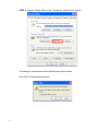
Download User Manual - Leviton.com
Transcript
Model 68A11-1 1.3 Mega Pixel Indoor/Outdoor Mini Dome IP Camera User Manual Table of Contents 1. 2. 3. 4. 5. Introduction ................................................................................................................. 1 1.1 Features ....................................................................................................................................... 1 1.2 Package Contents ....................................................................................................................... 2 1.3 Camera Overview ........................................................................................................................ 2 Preparations for IP Camera Setup ............................................................................ 4 2.1 System Requirements ................................................................................................................. 4 2.2 Ethernet Connection .................................................................................................................... 4 Deleting the Existing DC Viewer ............................................................................... 5 Accessing the Camera ............................................................................................... 7 Configuration & Operation....................................................................................... 13 5.1 Browser-based Viewer Introduction ........................................................................................... 13 5.2 Home Page ................................................................................................................................ 14 5.3 System Related Settings ........................................................................................................... 15 5.4 5.3.1 Host Name and System Time Setting ...................................................................... 16 5.3.2 Security..................................................................................................................... 17 5.3.3 Network .................................................................................................................... 19 5.3.4 DDNS ....................................................................................................................... 22 5.3.5 Mail ........................................................................................................................... 23 5.3.6 FTP ........................................................................................................................... 24 5.3.7 Motion Detection....................................................................................................... 25 5.3.8 Snapshot .................................................................................................................. 28 5.3.9 View Log File ............................................................................................................ 29 5.3.10 View User Information .............................................................................................. 30 5.3.11 View Parameters ...................................................................................................... 32 5.3.12 Factory Default ......................................................................................................... 33 5.3.13 Software Version ...................................................................................................... 34 5.3.14 Software Upgrade..................................................................................................... 35 Video and Audio Streaming Settings ......................................................................................... 38 5.4.1 Video Resolution and Rotate Type ........................................................................... 38 5.4.2 Video Compression .................................................................................................. 40 5.4.3 Video OCX Protocol ................................................................................................. 41 5.4.4 Video Frame Skip ..................................................................................................... 42 5.4.5 Audio Mode and Bit Rate Settings............................................................................ 43 5.5 5.6 Camera Settings ........................................................................................................................ 45 5.5.1 Exposure Setting ...................................................................................................... 45 5.5.2 White Balance Setting .............................................................................................. 46 5.5.3 Brightness Setting .................................................................................................... 47 5.5.4 Sharpness Setting .................................................................................................... 47 5.5.5 Contrast Setting ........................................................................................................ 47 5.5.6 Saturation ................................................................................................................. 48 5.5.7 Hue ........................................................................................................................... 48 5.5.8 TV System Setup...................................................................................................... 48 Logout ........................................................................................................................................ 49 Appendix A: Technical Specifications ........................................................................... 50 Appendix B: Internet Security Settings ......................................................................... 52 Appendix C: DC Viewer Download Procedure .............................................................. 56 1. Introduction The 1.3 Mega Pixel Indoor/Outdoor Mini Dome IP Camera is capable of serving real-time streaming video to various devices. It can be viewed at home or over the Internet on a PC, OmniTouch 5.7e, OmniTouch 10p, or handheld mobile device, such as PDA, Smartphone, or other device running Windows® Mobile operating system, using LEVITON Snap-Link Mobile (1120M) or LEVITON WL3 (1112). Additionally, it can be viewed on an iPhoneTM without any additional software. Since each Mini Dome IP Camera has a built-in web server and network interface, it may not require additional hardware, software, or programming (besides configuring its network settings) to view live video transmissions. After configuring its network settings, it can be accessed from anywhere with an Internet connection. In addition to MJPEG real time streaming, the Mini Dome IP Camera employs an H.264 main profile codec for a high resolution digital broadcast. With the Power over Ethernet (IEEE 802.3af) feature, there is no need for power outlets, which significantly reduces the cost of cabling and installation. Additionally, its light weight and compact size offer a quick and simple installation on the ceilings or walls inside or outside of houses and buildings. 1.1 Features • • • • • • 1/3” SONY progressive CMOS Simultaneous H.264 / MJPEG video stream (dual stream) Resolution: H.264 HD; MJPEG HD Digital Zoom Frame Rate: H.264 30fps@720p; MJPEG 30fps@720p Image Setting: Rotation: Flip, Mirror, and Rotate 180, Brightness, Sharpness, Contrast, White Balance, Exposure Control • Interface 10/100 Ethernet (RJ45) • Weatherproof Dongle Cable for outdoor use • Weatherproof (IP66 international standard) 1 1.2 Package Contents Please check the package contains the following items listed below. 68A11-1 Self-tapping Plastic Anchors Security Screw screws (×3) (×3) (×1) Security Torx Quick Start CD (w/ weatherproof dongle cable) Guide Rubber Washer Rubber Washer x 3, for baseplate X1, for casing safety screws 1.3 2 Camera Overview Designation Description 1 Reset Button Restore to default setting; press the button with a proper tool 2 Lens Rotate the lens right/left to adjust focus 3 Focus Fixed Screw Loosen the screw to adjust the lens 4 Tilt Fixed Screw Loosen the screw to adjust tilt angle Camera Overview Dimensions 3 2. Preparations for IP Camera Setup This chapter outlines information about system requirements for IP Dome Camera operation, power and Ethernet connection for Indoor/Outdoor IP Dome Camera, and access to the camera. 2.1 System Requirements To connect to the IP Dome Camera via a web browser, ensure your PC is connected to the network, and meet system requirements as described below. Items System Requirement Intel○ Pentium○ M, 2.16 GHz or Intel○ CoreTM2 Duo, R Personal Computer 2.2 R R 2.0 GHz, 2. 2 GB RAM or more Operating System Windows VISTA or Windows XP Web Browser Microsoft Internet Explorer 6.0 or later Network Card 10Base-T (10 Mbps) or 100Base-TX (100 Mbps) operation Viewer ActiveX control plug-in for Microsoft IE Ethernet Connection Please follow the instructions below to connect to the camera to the Ethernet. RJ45 Dongle Cable Connection RJ-45 Dongle Cable Connection: Run the Ethernet cable through the Waterproof RJ45 Screw-On Plug. Then connect one end of the Ethernet cable to the RJ45 dongle, tightening the sealing nut of the Waterproof RJ45 Screw-On Plug completely. Connect the other end of the Ethernet cable to a Power Sourcing Equipment (PSE) device, such as a PoE network switch, hub, or power injector which provides the power. 4 3. Deleting the Existing DC Viewer If you have already installed the DC Viewer on the PC, first delete the existing DC Viewer from the PC before accessing the Mini Dome IP Camera. Deleting the DC Viewer Click “Control Panel”, and then double-click “Add or Remove Programs.” In the “Currently installed programs” list, select “DCViewer” and click the “Remove” button to uninstall the existing DC Viewer as shown in the figure below. Deleting Temporary Internet Files To improve browser performance, it is suggested to clean up all of the Temporary Internet Files on the PC. The procedure is as follows: STEP 1: Click the “Tools” tab and select the option “Internet Options.” 5 STEP 2: Tap the “Delete Files” in the “Temporary Internet files” section. The dialog for confirmation will be displayed as shown below. Click “OK” to start deleting the files. 6 4. Accessing the Camera For initial access to the IP Dome Camera, you can search for the camera through the installer program: DeviceSearch.exe, which can be found in “DeviceSearch” folder on the supplied CD. Device Search Software Setup Step 1: Double-click on the program Device Search.exe (see the icon below): When the utility starts, click the “Device Search” button. Step 2: The security alert will be displayed. Click “Unblock” to continue. 7 Device Search Step 3: Click “Device Search” again, to find all available IP Dome Cameras. The IP Dome Camera’s default IP address is: 192.168.0.103. Step 4: Double-click or right-click and select “Browse” to access the camera directly via web browser. Step 5: An authentication window will appear. Enter the default username and password to access the IP Dome Camera. 8 The default login ID and password for the Administrator are: Login ID Password Admin 1234 NOTE: ID and password are case sensitive. NOTE: It is strongly advised that the you change the administrator’s password for the security reasons. Refer to section 5.3.2 Security for more details. Additionally, users can change the IP Dome Camera’s network property, from the device list. Refer to the following section for changing the IP Dome Camera’s network property. Example of Changing IP Dome Camera’s Network Property Users can directly change an IP Dome Camera’s network property, (e.g. from Static IP to DHCP), in the device list. The way to change the IP Dome Camera’s network property is specified below: Step 1: In the device list, click on the IP Dome Camera that you would like to change configure. On the selected item, right click and select “Network Setup”. Meanwhile, record the IP Dome Camera’s MAC address for future identification. 9 Step 2: The “Network Setup” page will be displayed. Select “DHCP,” and press the “Apply” button. Step 3: Click “OK”. Wait for one minute to re-search the IP Dome Camera. Step 4: Click the “Device Search” button to search all the devices. Then select the IP Dome Camera with the correct MAC address. Double-click on the IP Dome Camera, and the authentication window will be displayed. Step 5: Enter User name and Password to access the IP Dome Camera. 10 Installing DC Viewer Software Online For initial access to the IP Dome Camera, a client program, DC Viewer, will be automatically installed on your PC when connecting to the IP Dome Camera. If the web browser doesn’t allow the DC Viewer installation, please check the Internet security settings or ActiveX controls and plug-ins settings (see Appendix B: Internet Security Settings) to continue the process. The Information Bar (just below the Address bar) may come out and ask for permission to install the ActiveX Control for displaying video in the browser (see the figure below). Right-click on the Information Bar and select “Install ActiveX Control…” to allow the installation. Then the security warning window will be displayed. Click “Install” to continue the software installation. Click “Finish” to close the DC Viewer window when the download is finished. For the detailed software download procedure, please refer to Appendix C: DC Viewer Download Procedure. Once you login to the IP Dome Camera, you will see the Home page as shown below: 11 Administrator/User Privileges “Administrator” represents the person who can configure the IP Dome Camera and authorizes user access to the camera. “User” refers to whoever has access to the camera with limited authority. Lens Adjustment The image is displayed on the Home page when you successfully access the IP Dome Camera. Adjust the camera’s focus to produce a clear image. Please refer to the procedure below. Step 1: Unscrew the IP Dome Camera’s cover. Step 2: Loosen the focus fixed screw, and rotate the lens to adjust focus; loosen the tilt fixed screw, and adjust the camera’s tilt angle. 12 5. Configuration & Operation The IP Dome Camera is provided with a user-friendly browser-based configuration interface. 5.1 Browser-based Viewer Introduction The figure below shows the Home page of the IP Dome Camera user interface. At the bottom of the main page, you can adjust video display size (x1, x1/2 and full screen), select the video format, and save JPEG snapshots. There are five tabs: Home, System, Streaming, Camera and Logout on the top panel. Home Users can monitor live video of the targeted area. System setting Administrator can set host name, system time, root password, and network related settings. For additional details see section 5.3 System Related Settings. Streaming setting Administrator can modify video resolution and rotate typeon this page. 13 Camera setting Users can adjust various camera parameters, including Exposure, White Balance, Brightness, Sharpness, and Contrast. Logout Click on this tab to login to the IP Dome Camera with another username and password. 5.2 Home Page In the Home page, there are several function buttons right down the displayed image. Screen Size Adjustment Image display size can be adjusted to x1, x1/2, and full screen. Digital Zoom Control In the full screen mode, you can use digital zoom by rotating the mouse wheel (to zoom in/out) and drag the mouse into any direction. Snapshot Press the button and a JPEG snapshots will automatically be saved in the folder configured. The default folder for saving snapshots is: C:\. 14 5.3 System Related Settings The figure below shows all categories under the “System” tab. Each category in the left column is explained in the following sections. NOTE: The “System” configuration page is only accessible by the Administrator. 15 5.3.1 Host Name and System Time Setting Select <System> in the left column. The page is shown below. Host Name The name is for camera identification. If the Motion Detection function is enabled and is set to send an alarm message by Mail/FTP, the host name is used for the alarm message. Sync With Computer Time When this item is selected, the date and time display will be synchronized with the PC. Manual The Administrator can set date, time, and day manually. 16 5.3.2 Security Select <Security> in the left column. The page is shown below. Admin Password Change the administrator’s password by entering the new password in both text boxes. The input characters/numbers will be displayed as dots for security purposes. After clicking <Save>, the web browser will ask the Administrator for the new password. The maximum length of the password is 14 digits. NOTE: The following characters are valid: A-Z, a-z, 0-9, !#$%&’-.@^_~. Add User Type the new user's name and password and click <Add> to add the new user. Both user name and password can be up to 16 characters. The new user will be displayed in the user name list. There is a maximum of twenty user accounts. 17 Each user can be assigned the privileges of “Camera control”. • Camera control This item allows the appointed User to change camera parameters on the Camera Setting page. NOTE: This camera does not support I/O, Talk, or Listen function. Manage User Delete user To delete a user, select the user name from the user list that you wish to delete. Then click <Delete> to remove the user. Edit user Select a user name from the list. Click <Edit> to edit the user’s password and privilege. NOTE: You must enter the User password and function for the user. When finished, click <Save> to modify the account authority. 18 5.3.3 Network Select <Network> in the left column. The page is shown below. Users can choose to use a fixed IP address or dynamic (DHCP) IP address. The following describes the two ways of setting IP address. Get IP address automatically (DHCP) The camera’s default setting is “Use fixed IP address”. Please refer to the previous section Chapter 4. Accessing Camera for logging in with the default IP address. If “Get IP address automatically” is selected, after the IP Dome Camera restarts, users can search use the installer program: DeviceSearch.exe, which can be found in on the supplied CD. NOTE: Please record the IP Dome Camera’s MAC address, which can be found on the label of the camera, for future identification. 19 Use fixed IP address To setup a static IP address, select “Use fixed IP address” and move the cursor to the IP address box (as indicated below) and insert the new IP address, (e.g. 192.168.7.234), and then go to the Default gateway (explained latter) box and change its setting. Press “Save” to confirm and save the new setting. When using a static IP address to login to the IP Dome Camera, users can access it either through the “DeviceSearch” software (see Chapter 4. Accessing Camera) or by entering the IP address in the Address bar and press “Enter”. 20 General • IP address This is necessary for network identification. • Subnet mask This is used to determine if the destination is on the same subnet. The default value is “255.255.255.0”. • Default gateway This is the gateway used to forward frames to destinations in a different subnet. An invalid gateway setting will fail to transit to destinations in a different subnet. • Primary DNS Primary DNS is the primary domain name server that translates hostnames into IP addresses. • Secondary DNS Secondary DNS is a secondary domain name server used to backup the primary DNS. • Web Server port The default web server port is 80. Once the port is changed, the user must be notified of the change for the connection to be successful. For instance, when the Administrator changes the HTTP port from 80 to 8080 of the IP Camera which has an IP address of 192.168.0.103, the user must type “http://192.168.0.103:8080” in the web browser instead of “http://192.168.0.103”. Advanced • RTSP port RTSP port could be set from 1 to 65535. (Default Setting Port: 554, 1024 ~65535) • MJPEG over HTTP port The default setting of HTTP Port is 8008; available range: 1024 ~65535. NOTE: Choose a different port from the one set for the web server. 21 5.3.4 DDNS Dynamic Domain Name System (DDNS) allows a host name to be constantly synchronized with a dynamic IP address. In other words, it allows those using a dynamic IP address to be associated to a static domain name so others can connect to it by name. Enable DDNS Check this item to enable DDNS. Provider Select one of the DDNS host from the provider list. Host name Enter the registered domain name in this field. Username/E-mail Enter the username or email required by the DDNS provider for authentication. Password/Key Enter the password or key required by the DDNS provider for authentication. 22 5.3.5 Mail The Administrator can send an email via Simple Mail Transfer Protocol (SMTP) when motion is detected. SMTP is a protocol for sending email messages between servers. SMTP is a relatively simple, text-based protocol, where one or more recipients of a message are specified and the message text is transferred. The configuration page is shown as follows: Two sets of SMTP can be configured. Each set includes an SMTP Server, Account Name, Password, and E-mail Address settings. For SMTP server information, contact your Internet Service Provider for more specific information. 23 5.3.6 FTP The Administrator can configure alarm message to be sent to a specific File Transfer Protocol (FTP) site when motion is detected. Users can assign alarm message for up to two FTP sites. The FTP setting page is shown below. Enter the FTP details, which include server, server port, user name, password, and remote folder, in the fields. Press “Save” when finished. 24 5.3.7 Motion Detection The Motion Detection function allows detecting motion in the detected area that reaches/exceeds the determined sensitivity threshold value. On the Motion Detection setting page, there is a red frame on the displayed image and a motion indication window on the top of the image (see the figure shown above). The red frame is for defining the motion detection area. To change the size of the area, move the mouse cursor to the edge of the red frame and draw it outward/inward. Moving the mouse to the center of the red frame can shift the frame to the intended location. When motion is detected, the signals in the motion indication window will be shownt. Detailed settings of Motion Detection are described as follows: Active Motion Detection You will be able to turn on/off Motion Detection in System section. The default setting is Off. 25 Motion Detection Setting Users could adjust various parameters of Motion Detection in this section. • Sampling pixel interval [1-100]: The default value is 10, which means the system will take one sampling pixel for every 10 pixel. • Detection level [1-100]: The default level is 10. The item is used to set the detection level for each sampling pixel; the smaller the value, the more sensitive it is. • Sensitivity level [1-100]: The default level is 80, which means if 20% or more of the sampling pixels are detected differently, the system indicates motion. The larger the value, the more sensitive it is. When the value is larger, the red horizontal line in the motion indication window will be lower accordingly. • Time interval (sec) [0-7200]: The default interval is 10. The value is the interval between each time motion is detected. Action (Multi-option) The Administrator can specify alarm actions that will take place when motion is detected. All options are listed as follows: 26 • Send Alarm Message by FTP/Email The Administrator can select whether to send an alarm message by FTP and/or Email when motion is detected. • Upload Image by FTP The Administrator can assign an FTP site and configure various parameters as shown in the figure below. When motion is detected, event images will be uploaded to the configured FTP site. • Upload Image by E-Mail The Administrator can assign an email address and configure various parameters as shown in the figure below. When motion is detected, event images will be sent to the configured email address. NOTE: Make sure the SMTP or FTP configuration has been completed. See section 4.3.5 Mail and 4.3.6 FTP for further details. File Name The filename format for the uploaded images can be set in this section. Select the one that meets your requirements. Save Click the Save button to save all the Motion Detection settings. The figure below shows what it is displayed when motion is detected. 27 5.3.8 Snapshot The IP Dome Camera supports a JPEG snapshot function. Users can specify a storage location for the snapshots. The default setting is: C:\. Confirm the setting and press “Save:”. All the snapshots will be saved in the designate location. NOTE: Make sure the selected file path contains valid characters such as letters and numbers. 28 5.3.9 View Log File Click on the link to view the system log file. The content of the file provides useful information about configuration and connections after system boot-up. 29 5.3.10 View User Information The Administrator can view each user’s login information and privileges (see 5.3.2 Security). View User Login Information All the users in the network will be listed in the “User information” zone, as shown below. For example: User: 4321 This indicates that one of the user’s login credentials are: Username: User Password: 4321 30 View User Privilege Press “get user privacy” on the bottom of the page. view each user’s privileges. The Administrator can 31 5.3.11 View Parameters Click on this item to view the parameter settings for the entire system. 32 5.3.12 Factory Default The factory default setting page is shown below. Follow the instructions to reset the IP Dome Camera to the factory default setting if needed. Set Default Click on the “Set Default” button to recall the factory default settings. Then the system will restart in 30 seconds. NOTE: The IP address will be restored to default. Reboot Click on the “Reboot” button, and the system will restart without changing current settings. 33 5.3.13 Software Version The current software version is displayed on the software version page, as shown below. 34 5.3.14 Software Upgrade A software upgrade can be performed on the “Software Upgrade” page, as shown below. NOTE: Make sure the upgrade software file is available before beginning the software upgrade process. 35 The procedure for a software upgrade is as follows: Step 1: Click “Browse” and select the file to be uploaded. “userland.jffs2”. For example, NOTE: Do not change the upgrade file name, or the system will fail to find the file. Step 2: Pull down the upgrade file list and select the file you want to upgrade. In this case, select “userland.jffs2.” Step 3: Press “Upgrade”. The system will first check whether the upgrade file exists, and then will begin to upload the upgrade file. Subsequently, the upgrade status bar will display on the page. When it runs to 100%, the upgrade process is finished. 36 After the upgrade process is finished, the viewer will return to Home page. Step 4: Close the video browser. Step 5: Click “Control Panel”, and then double-click the “Add or Remove Programs” button. In the “Currently installed programs” list, select “DCViewer” and click “Remove” to uninstall the existing DCViewer. Step 6: Open a new web browser, log into the IP Camera, and then allow the automatic download of new DCViewer application. 37 5.4 Video and Audio Streaming Settings Press the”Streaming” tab on the top of the page. Under “Streaming”, the Administrator can configure specific video resolution, video compression mode, and video protocol. Additional details of these settings will be specified in the following sections. 5.4.1 Video Resolution and Rotate Type The video setting page is shown below: Video Format The IP Camera provides various video resolutions: • H.264 720p (30fps) + MJPEG 720p (30fps) • H.264 720p (30fps) + MJPEG D1 (30fps) • H.264 720p (30fps) + MJPEG CIF (30fps) Click “Save” to confirm the setting. 38 Video Rotate Type Users can change video display if necessary. The selectable video rotate types include Normal, Flip, Mirror, and 180 degree. Differences among these types are illustrated below. Suppose the displayed image of IP Dome Camera is shown as the figure below. To rotate the image, users can select “Flip”. Then the displayed image will be reversed as shown below. The following are descriptions for the different video rotate types. • Flip Select <Flip> to vertically rotate the image. • Mirror Select <Mirror> to horizontally rotate the image. • 180 Degree Select <180 Degree> to invert the image. Click “Save” to confirm the setting. 39 5.4.2 Video Compression Users can select a proper MJPEG/H.264 compression mode in the video compression page (see the figure below), depending on the application. MJPEG compression settings include: • • • high compression, low bitrate, low quality middle compression, default low compression, high bitrate, high quality H.264 compression settings include: • • • highest compression, lowest quality middle compression, default low compression, highest quality Users can also decide whether to display compression information on the Home page. Click “Save” to confirm the setting. 40 5.4.3 Video OCX Protocol In the Video OCX protocol setting page, users can select RTP over UDP, RTP over TCP, RTSP over HTTP, or MJPEG over HTTP, for streaming media over the network. In the case of multicast networking, users can select the Multicast mode. The page is shown as follows. Video OCX protocol setting options include: • RTP over UDP / RTP over RTSP(TCP) / RTSP over HTTP / MJPEG over HTTP Select a mode according to your data delivery requirements. • Multicast Mode Enter all required data, including multicast IP address, H.264 video port, MJPEG video port, audio port, and TTL into each blank. Click “Save” to confirm the setting. 41 5.4.4 Video Frame Skip Video frame skipping is for saving bandwidth if necessary. MJPEG/H.264 Frame Skip options include: • • • • No skipping, default Frame skipping at 5 frame internal (lowest frame loss rate) Frame skipping at 10 frame internal Frame skipping at 15 frame internal (highest frame loss rate) NOTE: Higher frame skipping rate will decrease video smoothness. 42 5.4.5 Audio Mode and Bit Rate Settings The audio setting page is show as below. On the Audio page, the Administrator can select one transmission mode and audio bit rate. Transmission Mode • Full-duplex (Talk and Listen simultaneously) In the Full-duplex mode, the local and remote sites can communicate with each other simultaneously (i.e. both sites can speak and be heard at the same time). NOTE: This option is not available on this camera. • Half-duplex (Talk or Listen, not at the same time) In the Half-duplex mode, the local/remote site can only talk or listen to the other site at a time. NOTE: This option is not available on this camera. 43 • Simplex (Talk only) In the Talk only Simplex mode, the local/remote site can only talk to the other site. NOTE: This option is not available on this camera. • Simplex (Listen only) In the Listen only Simplex mode, the local/remote site can only listen to the other site. NOTE: This option is not available on this camera. • Disable Select the item to turn off the audio transmission function. Bit Rate Selectable audio transmission bit rates include 16 kbps (G.726), 24 kbps (G.726), 32 kbps (G.726), 40 kbps (G.726), uLAW (G.711), and ALAW (G.711). Both uLAW and ALAW signify 64 kbps but in different compression formats. Higher bit rates will generate higher audio quality but require more bandwidth. Click “Save” to confirm the setting. 44 5.5 Camera Settings The figure below is the camera configuration page. Details of each parameter setting are described as follows. 5.5.1 Exposure Setting The Exposure dropdown menu is shown as follows: The exposure is the amount of light received by the image sensor and is determined by the width of the lens diaphragm opening (iris adjustment), the amount of exposure by the sensor (shutter speed), and other exposure parameters. 45 With this item, users can define how the Auto Exposure function works. Each exposure mode is specified as follows: Full Auto Mode In this mode, the camera’s Shutter Speed, IRIS, and AGC (Auto Gain Control) control circuits work together automatically to get consistent video output levels. The maximum shutter speed is adjustable from 1/30 to 1 sec. Fixed Shutter Mode In this mode, fixed shutter speed can be selected from the dropdown menu. The shutter speed range is from 1/10000 to 1 sec. with 19 options. Users can select suitable shutter speed according to the environmental illumination. 5.5.2 White Balance Setting The White Balance dropdown menu is shown as follows: A camera needs to find a reference color temperature, which is a way of measuring the quality of the light source, for calculating all the other colors. The unit for measuring this ratio is in degrees Kelvin (K). Users can select one of the White Balance Control modes according to the operating environment. The following table shows the color temperature of some light sources for reference. Light Sources Cloudy Sky Noon Sun and Clear Sky Household Lighting 46 Color Temperature in K 6,000 to 8,000 6,500 2,500 to 3,000 75-Watt Bulb 2,820 Candle Flame 1,200 to 1,500 Auto Mode In this mode, white balance works within its color temperature range and calculates the best white balance. Manual Mode In this mode, users can change the White Balance value manually by adjusting the R gain and B gain. Press <SET> to confirm the new setting. 5.5.3 Brightness Setting Users can adjust the image’s brightness by adjusting the item. The value of the Backlight is adjustable from -12 (dim) to +13 (brightest). Press <SET> to confirm the new setting. 5.5.4 Sharpness Setting Increasing the sharpness level can make the image look sharper, especially to enhance the object’s edges. The value of sharpness is adjustable from -2 to +13 (sharpest). Press <SET> to confirm the new setting. 5.5.5 Contrast Setting Users can correct the contrast of the entire image by adjusting the Contrast level, ranging from -6 to +19. 47 5.5.6 Saturation Users can adjust the saturation of color components in an image through the Saturation function, which is adjustable from -6 to +19. 5.5.7 Hue Users can adjust the hue of color components in an image through the Hue function, which is adjustable from -12 to +13. 5.5.8 TV System Setup Select the video format that matches the present TV system. 48 5.6 Logout Press the “Logout” tab on the top of the page, and the login window will be displayed. This enables a different user to login. 49 Appendix A: Technical Specifications Camera Image Sensor 1/3" Sony Progressive CMOS Picture Elements 1280(H) x 1024(V) Shutter Speed 1 - 1/50000 sec. Lens Fixed Lens F 1.8 / f = 4.3 mm Operation Video Compression H.264 Main Profile / MJPEG Video Streaming Simultaneously H.264 + MJPEG H.264: up to 1280 x 720 Resolution MJPEG: up to 1280 x 720 H.264: 25/30 fps Frame Rate Image Setting MJPEG: 25/30 fps Brightness Manual Exposure Auto / Manual Sharpness Manual Contrast Manual White Balance Digital Zoom Auto / Manual 1x - 12x Image Rotation Flip, Mirror, and 180-Rotate Motion detection ON / OFF Privacy Mask ON / OFF Privacy Mask Type Mosaic, Transparent, Color Network Interface 10/100Mb Ethernet (RJ45) TCP/IP, UDP, RTP, RTSP, HTTP, ICMP,FTP, SMTP, DHCP, Protocol and IGMP Password Levels User and Administrator Internet Browser Internet Explorer (6.0+) User Account 20 Mechanical Lens Mounting Connectors 50 M12 Board Lens Ethernet RJ45 General Operating Temperature 0°C - 50°C Humidity: 10% to 90%, No Condensation Power Source PoE Power Consumption 3W Regulatory CE, FCC, RoHS Compliant Dimension 110 x 47 mm (4.3 x 1.9 Inches) Weight 180 g (0.40 lb) 51 Appendix B: Internet Security Settings If the ActiveX control installation is blocked, either set Internet security level to default or change the ActiveX controls and plug-ins settings. Internet Security Level: Default Step 1: Start the Internet Explorer (IE). Step 2: Select <Tools> from the main menu of the browser. Then Click <Internet Options>. Step 3: Click the <Security> tab, and select <Internet>. Step 4: Press “Default Level” (see the figure above) and click “OK” to confirm the setting. Close the browser, and then open a new one to access the IP Dome Camera. 52 53 ActiveX Controls and Plug-ins Settings Step 1-3: Refer to the previous section above. Step 4: Press “Custom Level” (see the figure below) to change the ActiveX controls and plug-ins settings. The Security Settings screen is displayed as below: 54 
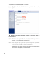
Step 5: Under “ActiveX controls and plug-ins”, set ALL items (as listed below) to <Enable> or <Prompt>. ActiveX controls and plug-ins settings: 1. Automatic prompting for ActiveX controls 2. Binary and scrip behaviors 3. Download signed ActiveX controls 4. Download using ActiveX controls 5. Initialize and script ActiveX not marked as safe 6. Run ActiveX controls and plug-ins 7. Script ActiveX controls marked safe for scripting Step 6: Click <OK> to accept the settings and close the <Security> screen. Step 7: Click <OK> to close the Internet Options screen. Step 8: Close the browser, and then open a new one to access the IP Dome Camera. 55 Appendix C: DC Viewer Download Procedure The procedure of DC Viewer software download is specified as follows. Step 1: In the DC Viewer installation page, click “Next” for starting the installation. Step 2: Wait while the software is installed. 56 Step 3: Click “Finish” to close the DC Viewer installation page. Then, the IP Camera’s Home page will display as follows: 57 FOR CANADA ONLY For warranty information and/or product returns, residents of Canada should contact Leviton in writing at Leviton Manufacturing of Canada Ltd to the attention of the Quality Assurance Department, 165 Hymus Blvd, Pointe-Claire (Quebec), Canada H9R 1E9 or by telephone at 1 800 405-5320. LEVITON LIMITED WARRANTY Leviton warrants to the original consumer purchaser and not for the benefit of anyone else that products manufactured by Leviton under the Leviton brand name (“Product”) will be free from defects in material and workmanship for the time periods indicated below, whichever is shorter: • OmniPro II and Lumina Pro: three (3) years from installation or 42 months from manufacture date. • OmniLT, Omni IIe, and Lumina: two (2) years from installation or 30 months from manufacture date. • Thermostats, Accessories: two (2) years from installation or 30 months from manufacture date. • Batteries: Rechargeable batteries in products are warranted for ninety (90) days from date of purchase. Note: Primary (non-rechargeable) batteries shipped in products are not warranted. Products with Windows® Operating Systems: During the warranty period, Leviton will restore corrupted operating systems to factory default at no charge, provided that the product has been used as originally intended. Installation of non-Leviton software or modification of the operating system voids this warranty. Leviton’s obligation under this Limited Warranty is limited to the repair or replacement, at Leviton’s option, of Product that fails due to defect in material or workmanship. Leviton reserves the right to replace product under this Limited Warranty with new or remanufactured product. Leviton will not be responsible for labor costs of removal or reinstallation of Product. The repaired or replaced product is then warranted under the terms of this Limited Warranty for the remainder of the Limited Warranty time period or ninety (90) days, whichever is longer. This Limited Warranty does not cover PC-based software products. Leviton is not responsible for conditions or applications beyond Leviton’s control. Leviton is not responsible for issues related to improper installation, including failure to follow written Installation and operation instructions, normal wear and tear, catastrophe, fault or negligence of the user or other problems external to the Product. To view complete warranty and instructions for returning product, please visit us at www.leviton.com. Copyright and Trademark Information This document and all its contents herein are subject to and protected by international copyright and other intellectual property rights and are the property of Leviton Manufacturing Co., Inc, its subsidiaries, affiliates and/or licensors. © 2013 Leviton Manufacturing Co., Inc. All rights reserved. Use herein of third party trademarks, service marks, trade names, brand names and/or product names are for informational purposes only, are/may be the trademarks of their respective owners; such use is not meant to imply affiliation, sponsorship, or endorsement. No part of this document may be reproduced, transmitted or transcribed without the express written permission of Leviton Manufacturing Co., Inc. For Technical Assistance Call: 1-800-824-3005 (U.S.A. Only) www.leviton.com PK-93499-10-B0-5AAR2133