1
ORTHOPANTOMOGRAPH®
OP30
Digital Panoramic X-ray Unit
Service manual
Number 208711 rev. 1 (2013-01)
ORTHOPANTOMOGRAPH® OP30
Copyright
Contents
Document code: 208711 ver. 1 (2013-01)
Copyright © 2009 by PaloDEx Group Oy.
All rights reserved.
ORTHOPANTOMOGRAPH ® / INSTRUMENTARIUM
DENTAL™/CLINIVIEW™ is a registered trademark/ a
common law trademark of Instrumentarium Dental, PaloDEx
Group Oy.
Documentation, trademark and the software are copyrighted
with all rights reserved. Under the copyright laws the
documentation may not be copied, photocopied, reproduced,
translated, or reduced to any electronic medium or machine
readable form in whole or part, without the prior written
permission of INSTRUMENTARIUM DENTAL.
The original language of this manual is English.
INSTRUMENTARIUM DENTAL reserves the right to make
changes in specification and features shown herein, or
discontinue the product described at any time without notice
or obligation. Contact your INSTRUMENTARIUM DENTAL's
representative for the most current information.
Manufactured by
Instrumentarium Dental
Nahkelantie 160 (P.O. Box 20)
FI-04300 Tuusula
FINLAND
Tel. +358 (0)10 270 2000
Fax. +358 9 851 4048
For service, contact your local distributor.
Service manual
III
Contents
IV
ORTHOPANTOMOGRAPH® OP30
Service manual
ORTHOPANTOMOGRAPH® OP30
Contents
Contents
1. General Information .......................................................................................... 1
1.1 Introduction ................................................................................................... 1
1.2 Associated documentation ............................................................................ 1
1.3 Service precautions and warnings ................................................................ 1
Servicing precautions.................................................................................... 1
Warning - Radiation Safety ........................................................................... 2
Warning - Mechanical safety ......................................................................... 2
Warning - Electrical Safety ............................................................................ 2
Caution - electrostatic discharge................................................................... 3
Warning - Explosion hazard .......................................................................... 4
Warning - Cleaning the unit........................................................................... 4
1.4 Unauthorized Modifications ........................................................................... 4
1.5 Disclaimer ..................................................................................................... 4
1.6 Unit maintenance .......................................................................................... 5
Exposure switch and cable ........................................................................... 5
mA test .......................................................................................................... 5
kV test ........................................................................................................... 6
Beam alignment test .................................................................................... 7
Ground test .................................................................................................. 7
Motor movements ......................................................................................... 7
Position detectors ......................................................................................... 7
Patient Positioning Lasers ............................................................................ 8
Mains power supply cable............................................................................. 8
Tubehead ...................................................................................................... 8
Covers and Labels ........................................................................................ 8
Fire risk ......................................................................................................... 8
1.7 Disposal ........................................................................................................ 9
Service manual
V
Contents
ORTHOPANTOMOGRAPH® OP30
2. Unit description ............................................................................................... 10
2.1 The ORTHOPANTOMOGRAPH® OP30 ...................................................... 10
2.2 The main parts and assemblies ..................................................................11
2.3 Unit dimensions ........................................................................................... 14
2.4 Mechanical description ................................................................................ 15
2.5 Electrical description ................................................................................... 17
Circuit boards .............................................................................................. 17
Power supply .............................................................................................. 17
Main fuses .................................................................................................. 17
Unit control ................................................................................................. 18
Motors and motor control ............................................................................ 18
Exposure logic ............................................................................................ 19
Position control ........................................................................................... 20
A overview of the Imaging Chain ................................................................ 20
2.6 Wiring diagrams - overview ......................................................................... 22
2.7 Block diagram ............................................................................................. 25
2.8 Fuse diagram .............................................................................................. 26
3. Circuit Boards .................................................................................................. 27
3.1 L900, Display adapter ................................................................................. 27
3.2 L1200 CPU Board ....................................................................................... 29
3.3 L1500, CCD Power Supply ......................................................................... 32
3.4 L1600, Z-Motor Driver ................................................................................. 36
3.5 L1700 Connector Board .............................................................................. 40
3.6 L1800, Generator Board ............................................................................. 43
3.7 P1910, PFC Board ...................................................................................... 47
3.8 L1300 Interface Board ................................................................................ 51
3.9 L2100 Rotation Position Sensor Board ...................................................... 52
3.10 R5100, 3-Phase Microstepper Driver ........................................................ 54
3.11 CCD Sensor / Filter board ......................................................................... 56
VI
Service manual
ORTHOPANTOMOGRAPH® OP30
Contents
4. Troubleshooting .............................................................................................. 60
4.1 Initial checks ................................................................................................ 60
Restarting the unit ....................................................................................... 60
Error Codes................................................................................................. 60
Checking circuit boards............................................................................... 60
Checking cables and connectors ................................................................ 61
Power supply problems............................................................................... 61
4.2 Problems during start up ............................................................................. 62
Nothing happens when the unit is switched on ........................................... 62
Error E 3 (CFG Data lost) ........................................................................... 64
Error E 5 (Line voltage out of limits)............................................................ 64
Error E 8 (File system failure) ..................................................................... 65
Error E16 (Z lift not allowed due to duty cycle) ........................................... 65
Error E 18 (Display not connected) ............................................................. 65
Error E 19 (Exposure switch stuck down) ................................................... 66
Error E20 (PCF: POWERGOOD signal is down)
................................ 66
Error E22 (Button stuck)
..................................................................... 66
4.3 Problems while preparing the unit for an exposure ..................................... 67
Image of emergency button appears on main display ................................ 67
The side control panel Return key does not work ....................................... 67
Error E 7 (Opto or r-motor failed during r-movement) ................................. 67
Rotating unit stop rotating, no error code.................................................... 68
Patient positioning light(s) do not come on ................................................. 68
Up/down (Z-motor) keys do not work .......................................................... 69
4.4 Problems during exposure .......................................................................... 71
Nothing happens when the exposure button is pressed ............................. 71
Error code H1 (Exposure interupted) .......................................................... 71
Error codes E0, E1 and E2 ......................................................................... 72
Error E 10 (CCD initialization/configuration failure) .................................... 74
Error E 11 (CCD power failure) ................................................................... 74
Error E 12 (CCD line failure) ....................................................................... 75
Error E 13 (CCD Configuration checksum failure) ...................................... 75
Service manual
VII
Contents
ORTHOPANTOMOGRAPH® OP30
4.5 Problems after exposure ............................................................................. 76
Error E 4 (Tubehead too hot) ...................................................................... 76
Vertical white stripes on the image ............................................................. 76
Horizontal white stripes on the image ......................................................... 76
4.6 Bad quality images ...................................................................................... 77
Incorrect patient positioning ........................................................................ 77
A badly aligned unit ..................................................................................... 77
The CCD sensor is not calibrated ............................................................... 77
5. S2terminal and service commands ............................................................... 78
5.1 Using the S2terminal ................................................................................... 78
5.2 The Service commands............................................................................... 81
6. Updating unit firmware, core and display graphics ..................................... 89
6.1 Firmware zip file .......................................................................................... 89
6.2 Upgrading the unit firmware ........................................................................ 89
7. Replacing parts................................................................................................ 90
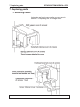
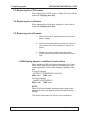
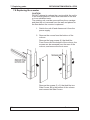
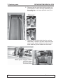
7.1 Removing covers ........................................................................................ 90
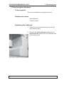
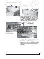
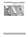
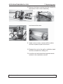
7.2 Replacing the tubehead .............................................................................. 91
Tools required ............................................................................................ 91
Replacement parts ...................................................................................... 91
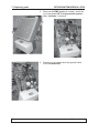
Replacing the tubehead .............................................................................. 91
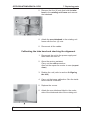
Calibrating the tube head and checking the alignment ............................... 93
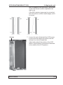
7.3 Replacing the CCD sensor .......................................................................... 94
7.4 Replacing the collimator .............................................................................. 94
7.5 Replacing circuit boards .............................................................................. 94
L900 Display adaptor - additional instructions ............................................ 94
L1800 Generator board - additional instructions ......................................... 95
L1700 Connector board - additional instructions ........................................ 95
L1200 CPU board - additional instructions ................................................. 95
L1500 Power Supply board - additional instructions ................................... 95
L1910 PFC board - additional instructions .................................................. 95
7.6 Replacing the z-motor ................................................................................. 96
VIII
Service manual
ORTHOPANTOMOGRAPH® OP30
Contents
8. Aligning the unit ............................................................................................ 102
8.1 Removing the covers ................................................................................ 102
8.2 Checking and Aligning the CCD Sensor ................................................... 102
8.3 Checking and adjusting the position of the collimator ............................... 104
8.4 Checking and adjusting the Chin Support ................................................. 107
8.5 Checking and adjusting the focal trough ................................................... 109
8.6 Recheck the alignment ...............................................................................112
8.7 Calibrating the CCD sensor .......................................................................112
Service manual
IX
ORTHOPANTOMOGRAPH® OP30
1. General information
1. General Information
1.1 Introduction
This manual describes how to service second generation OP30, ORTHOPANTOMOGRAPH® OP30 Digital
Panoramic X-ray Unit.
There are two versions of the unit:
- first generation these have serial numbers starting
with IV.
- second generation these have serial numbers starting
with IO.
1.2 Associated documentation
The unit user's manual.
The unit installation manual.
The unit spare-parts manual.
1.3 Service precautions and warnings
Servicing precautions
Only service personnel trained and approved by the
manufacturer of the unit are allowed to service the unit.
Before attempting to service the unit make sure that you
know how to operate it. Read the unit user's manual.
Read and familiarize yourself with the warnings and
precautions listed in the unit user's manual.
Only use original INSTRUMENTARIUM DENTAL™
Systems spare parts when repairing the unit or replacing parts.
The unit can operate using voltages:
100 to 120 VAC or 220 to 240 VAC.
The only difference between the two versions is the
supplied power cable.
Service manual
1
ORTHOPANTOMOGRAPH® OP30
1. General Information
Warning - Radiation Safety
Before servicing the unit familiarize yourself with local
and national radiation safety standards and requirements relating to dental x-ray equipment.
When taking test exposures take adequate precautions
to protect yourself from radiation. Stand behind a suitable radiation shield positioned at least two metres (six
feet) from the unit.
Warning - Mechanical safety
Disconnect the unit from the main power supply before
removing any covers.
Disconnect the unit from the main power supply before
repairing or replacing mechanical parts or installing accessories.
Be careful when operating the unit not to get body parts
or clothing trapped between moving parts.
During operation some surfaces and components may
become hot. Take precautions to avoid burning yourself.
The aperture plate in the collimator is made of lead (Pb)
which is toxic. Do not touch it with your bare hands.
Do not open the tubehead. There are no serviceable
parts, mechanical or electrical, inside the tubehead.
Warning - Electrical Safety
Disconnect the unit from the main power supply before
replacing circuit boards or other electrical components.
If there are capacitors on a circuit board or electrical
component wait ten (10) minutes, after disconnecting
the unit from the power supply, before handling the
board or component.
2
Service manual
ORTHOPANTOMOGRAPH® OP30
1. General information
If you have to leave the unit unattended during servicing
or maintenance, disconnect the unit from main power
supply to protect people, who may touch the unit, from
electric shock.
This unit should be used only in areas that are provided
with a protective earth connection to ensure an equipotential ground connection.
Caution - electrostatic discharge
Electrostatic Discharge (ESD) can damage or destroy
electronic components.
When servicing the unit take precautions to avoid electrostatic build up and discharge (ESD). Follow the recommendations for the prevention of ESD that are used
in the country in which you are working. If no recommendations are available, follow the guidelines below:
Service manual
-
Leave all new or replacement circuit boards and
electrical parts in their protective packaging until the
boards are needed.
-
Before handling circuit boards and electrical parts
make sure that any static electricity charge that has
built up in you body is discharged.
-
When examining and checking circuit boards use an
antistatic wrist wrap which is connected to a ground
point through a 1 Mohm current limiting cable. For a
ground point use water pipes, radiators or other objects that are known to be connected to the ground.
Also use a cable to connect the unit to the same
ground potential as the wrist wrap.
-
When handling circuit boards hold them by their
edges and do not touch any components or connectors.
-
If an antistatic mat is used, connect the wrist wrap
to the mat and the mat to the ground potential.
-
Wash the wrist wrap and check that it is in good
condition frequently.
3
ORTHOPANTOMOGRAPH® OP30
1. General Information
Warning - Explosion hazard
Certain disinfectants and cleaning agents may vaporize
to form an explosive vapour. If such chemicals are used
the vapour should be allowed to disperse before switching the unit on.
Warning - Cleaning the unit
Switch the unit off and disconnect it from the main
power supply before cleaning or disinfecting the unit.
1.4 Unauthorized Modifications
Unauthorized changes or modifications to any part of
the unit or its equipment can have hazardous consequences. Changes or modifications must not be made
unless specifically authorized by the manufacturer of
the unit.
When properly assembled with a compatible beam-limiting unit, the diagnostic source assembly will fully meet
the United States of America Federal Performance
Standards for Diagnostic X-Ray Systems and Their
Components (21 CFR 1020. 30-32) provided no components or parts are removed from the unit and no unauthorized adjustments are made to the beam-limiting unit
or tube housing assembly.
Never remove or remanufacture any part of the tube
housing assembly or beam-limiting unit.
Never adjust any part of the beam-limiting unit unless
under the direction of the manufacturer of the unit or
their authorized distributor(s).
1.5 Disclaimer
The manufacturer of the unit shall have no liability for
consequential damages, personal injury, loss, damage
or expense directly or indirectly arising from the use of
its products. No agent, distributor or other party is authorized to make any warranty or other liability on behalf
of the manufacturer of the unit with respect to its products.
4
Service manual
ORTHOPANTOMOGRAPH® OP30
1. General information
1.6 Yearly maintenance
The following tests and inspections must be carried out
annualy by an authorized service person to verify that
the unit meets the specifications and performance criteria essential for correct and safe operation.
When taking measurements that require a multimeter,
always use a digital multimeter (DMM).
Exposure switch and cable
Check that the exposure switch and cable are not damaged. Check that the exposure switch button does
not stick down when pressed. Take a test exposure to
check that the exposure switch functions correctly. Replace the exposure switch and cable they are damaged
or do not function correctly.
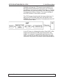
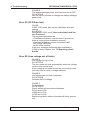
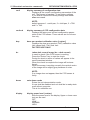
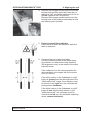
mA test
WARNING: X-rays are generated when this test is carried out. PROTECT YOURSELF FROM RADIATION.
1. Connect the +probe of a DMM to test pin TP18
(mAfb) and the -probe to TP17(GND) on the L1800
Generator board.
2. Select service command exp and an exposure time
of 2000 ms (refer to section 4 Service assistant and
service functions, in this manual).
3. Protect yourself from radiation and take an exposure. Check the feedback values from the DMM.
The feedback values must be within the tolerance.
Selected mA
6
8
10
12
mAfb (V)
1.2
1.58
2.0
2.4
Tolerance (V)
±0.15 (1.05 - 1.35)
±0.15 (1.43 - 1.73)
±0.15 (1.85 - 2.15)
±0.15 (2.25 - 2.55)
If the value is not within the tolerance, recalibrate
the Generator board, see section 5.2 Service Commands (the calib command).
Service manual
5
ORTHOPANTOMOGRAPH® OP30
1. General Information
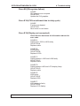
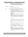
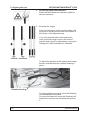
kV test
WARNING: X-rays are generated when this test is carried out. PROTECT YOURSELF FROM RADIATION.
1. Connect the +probe of a DMM to test pin TP14
(kVfb) and the -probe to TP17(GND) on the Generator board.
2. Select service command exp and an exposure time
of 2000 ms (refer to section 4 Service assistant and
service functions, in this manual).
3. Protect yourself from radiation and take an exposure. Check the feedback values from the DMM.
The feedback values must be within the tolerances.
Selected kV
66
70
73
77
81
kVfb
3.00
3.18
3.32
3.50
3.68
Tolerance (V)
±0.1 (2.90 - 3.10)
±0.1 (3.08 - 3.28)
±0.1 (3.22 - 3.42)
±0.1 (3.40 - 3.60)
±0.1 (3.58 - 3.78)
If the values are not within the tolerances, recalibrate the Generator board, see section 5.2 Service
Commands (the calib command).
Beam alignment test
Check the beam alignment. Refer to the Installation and
set-up manual for information on how to do this.
Ground test
Disconnect the unit from the main power supply before
carrying out this test.
For ME EQUIPMENT with an APPLIANCE INLET the
impedance between the earth pin in the APPLIANCE
INLET and any part that is PROTECTIVELY EARTHED
shall not exceed 0.1 ohm. The grounding resistance is
measured between APPLIANCE INLET ground pin and
any metal part of the unit.
The resistance MUST be <0.1 ohm.
6
Service manual
ORTHOPANTOMOGRAPH® OP30
1. General information
Motor movements
Switch the unit off and then manually rotate the rotating
unit to check that the stepper motor moves freely and
without any looseness.
Switch the T-mode "test" and then take an exposure to
check that the motors operate smoothly and without any
noise.
Press the up/down keys to check the Z-motor (vertical
carriage movement). The motor must operate smoothly
and without any noise.
Position detectors
Press the up key and drive the unit up. Make sure that
the unit stops moving at its uppermost position.
Press the down key and drive the unit down. Make sure
that the unit stops moving at its lowermost position.
Manually rotate the rotating unit to one of its end positions and then press the return button and make sure
that the rotating unit returns to the ready position. Repeat the test for the other end position.
Use service command optotest, see section 5.2 Service Commands, to check the rotating unit optosensors.
Manually turn the rotating unit in one direction and then
press return. Repeat for the other direction.
Patient Positioning Lasers
Check that the patient positioning lasers work and are
positioned correctly. Refer to the Installation and set-up
manual for information on how to do this.
Mains power supply cable
Check the condition of main power supply cable and
replace it if damaged.
Service manual
7
ORTHOPANTOMOGRAPH® OP30
1. General Information
Tubehead
Make sure that oil is not leaking from the tubehead. If
the tubehead shows signs of oil leakage, replace it.
Covers and Labels
Check that all covers are correctly installed and in good
condition. Also check that all the labels are attached to
the unit and that they are all legible.
Fire risk
WARNING: Disconnect the unit from the main power
supply before carrying out the next task.
Use a vacuum cleaner to remove all dust that has accumulated inside the unit and cover air vents to eliminate
the risk of fire. Remove all dust from the circuit boards,
and pay special attention to the Generator board L1800
and PFC P1910.
1.7 Disposal
At the end of useful working life of the unit, its spare
and replacement parts and accessories make sure that
you follow all local, national and international regulations regarding the correct and safe disposal and/or
recycling of the unit, its spare and replacement parts
and accessories.
The unit and its spare parts and accessories may include parts that are made of or include materials that
are non-environmentally friendly or hazardous. These
parts must be disposed of in accordance with all local, national and international regulations regarding the
disposal of non-environmentally friendly or hazardous
materials.
8
Service manual
ORTHOPANTOMOGRAPH® OP30
1. General information
The following hazardous materials and substances can
be found in the unit, its spare and replacement parts
and assemblies:
- Lead (Pb):
circuit boards, tubehead, collimator,
CCD sensor assembly
- Cadmium (Cd):
none
- Mercury (Mg):
none
- PBB Polybrominated biphenyls:
none
- PBDE polybrominated diphenyl ethers:
none
Other materials and substances in the unit, its spare
parts and assemblies that could be hazardous and are
non-environmentally friendly are:
- Mineral oil:
tubehead
Service manual
9
2. Unit Description
ORTHOPANTOMOGRAPH® OP30
2. Unit description
2.1 The ORTHOPANTOMOGRAPH® OP30
The ORTHOPANTOMOGRAPH® OP30 extraoral x-ray
unit is designed to take exposures of the dento-maxillofacial region.
The unit cannot be used to take x-ray exposures of any
other part of the human anatomy.
The unit can be used to take adult panoramic (full
width), child panoramic (reduced width), TMJ and bitewing images.
The unit can operate using voltages:
from 100 to 120 VAC or 220 to 240 VAC
The unit is used with a PC in which Cliniview or some
other MDD approved dental imaging software are installed.
For information on how to use the unit refer to the User
Manual.
10
Service Manual
ORTHOPANTOMOGRAPH® OP30
2. Unit Description
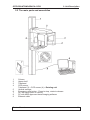
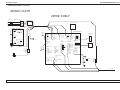
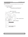
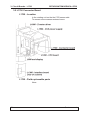
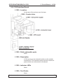
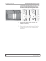
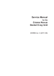
2.2 The main parts and assemblies
1
2
3
4
5
6
7
8
9
Column
Upper shelf
Tubehead
CCD sensor
Tubehead (3) + CCD sensor (4) = Rotating unit
Vertical carriage
Emergency stop button - Press to stop, rotate to release.
On / off switch (rear of column)
PC with MDD approved dental imaging software
Ethernet cable
Service Manual
11
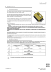
2. Unit Description
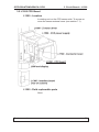
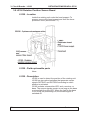
1
2
3
4
5
6
7
8
12
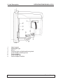
ORTHOPANTOMOGRAPH® OP30
Head support
Midsaggital light
Mirror
Frankfort light and light positioning knob
Focal trough positioning knob
Patient support
Focal trough light
Patient support handles
Service Manual
ORTHOPANTOMOGRAPH® OP30
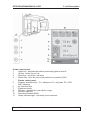
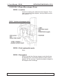
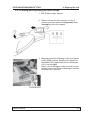
2. Unit Description
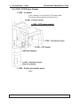
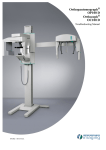
A side control panel
1
Lights key - switches the patient positioning lights on and off
2
Up key - drives the unit up
3
Down key - drives the unit down
4
Return key - drive the unit to the patient in/out position (PIO)
5
6
7
8
9
10
11
B main control panel
Program selection keys - P1 = adult pan, P2 = child pan, P3 = TMJ,
BW = bitewing
kV selection keys
Exposure values
Test key - operated the unit without x-rays
Service mode key
Dose Area Product (DAP)
Ready indicator light - unit ready for an exposure
Service Manual
13
2. Unit Description
ORTHOPANTOMOGRAPH® OP30
2.3 Unit dimensions
14
Service Manual
ORTHOPANTOMOGRAPH® OP30
2. Unit Description
2.4 Mechanical description
The unit comprises a column, a motorized carriage,
an upper shelf, a rotating unit and a patient support
assembly.
The column is permanently fixed to the wall, using wall
bracket and, if required or necessary to the floor.
The unit can also be used free standing but it must be
attached to the show stand (part no. 9802666).
The motorized carriage is attached to the column and
can slide up and down the column (Z-movement, for
adjusting the height of the unit). The upper shelf is attached to the top of the motorized carriage.
The rotating unit, which comprises the tubehead and
collimator and the CCD sensor, is attached to the underside of the upper shelf. The rotating unit rotates to
take panoramic exposures (R-movement).
Service Manual
15
2. Unit Description
ORTHOPANTOMOGRAPH® OP30
Inside the tubehead there is the x-ray tube. It is a fixed
tungsten anode type.
The patient support assembly is attached to the bottom of the vertical carriage. It comprises handgrips for
the patient to hold and the patient support.
The chin rest supports the patients lower jaw and the
two temple supports on the head support hold the upper part of the patient's skull.
There are three patient positioning lasers, midsagittal
laser, Frankfort (horizontal) laser and Focal through
light.
16
Service Manual
ORTHOPANTOMOGRAPH® OP30
2. Unit Description
2.5 Electrical description
Circuit boards
Circuit boards are described in detail in section 3. Circuit Boards.
Power supply
Mains voltage is supplied to P1910 PFC Power Supply
Board via L1600 Z-Motor Driver. P1910 supplies power
to L1800 Generator Board and L1500 Power Supply
board which supplies low voltages to all the other circuit
boards.
The power for the AC-motor (Z-Motor) comes from an
autotransformer that is automatically set to the correct
voltage. The Z-Motor input voltage is always 230 VAC.
The autotransformer is connected to L1600.
Main fuses
Two T-10A-H-250V.
Dimensions 6.3x32mm / 1/4x1-1/4". UL approved.
They are located below the main power supply cable at
the rear of the column.
Service Manual
17
ORTHOPANTOMOGRAPH® OP30
2. Unit Description
Unit control
The unit is controlled by a microprocessor on L1200
(CPU board). It continually monitors and controls the
operation of the unit. A serial peripheral interface communication protocol (SPI - RS485) and direct digital I/O
are used to monitor most of the unit functions.
The microprocessor:
- monitors the optosensors
- monitors control (touch) panel keys
- controls unit movements during exposures
- starts, controls and stops x-ray generation
- controls the digital imaging chain
- controls unit / PC communications
The necessary unit settings and parameters for all the
imaging programs are stored in the memory which is
also on L1200.
Motors and motor control
There is one stepper motor and one AC-motor in the
unit.
The stepper motor drives the rotating unit (R-movement). The stepper motor is driven and controlled by
R5100 (3-Phase Microstepper Driver).
The AC-motor (Z-motor) adjusts the height of the unit
(Z-movement), and the motor is activated by L1600. To
activate the Z-motor L1600 must receive a control signal from L1200 and a separate control (enable) signal
from the Z-movement (up/down) keys.
An emergency switch on the front of unit disables the Zmotor (Z-movement) and stepper motor (R-movement)
when pressed.
18
Service Manual
ORTHOPANTOMOGRAPH® OP30
2. Unit Description
Exposure logic
An exposure can only be taken when the unit is in the
ready state (the exposure ready light on the control
panel is on) and the exposure button is pressed and
held down.
The Generator board receives the correct kV and mA
references from the CPU. A few milliseconds after the
exposure button is pressed (Expsw) preheat is enabled
(Preh). After 800ms the exposure will start (ExpEna).
The tubehead will receive power from the Generator
board and the Generator board will also start to regulate
the mA and kV according to mA- and kV- feedback.
Service Manual
19
ORTHOPANTOMOGRAPH® OP30
2. Unit Description
Position control
The position of the rotating unit (R-movement) is monitored by optosensors on L2100 (Rotation Position Sensor Circuit). The optosensors indicate in which sector
the rotating unit is. The optosensors ensure that the
rotating unit is in the correct position, start or PIO (Patient In/Out), for an exposure.
The statuses of the optosensors are monitored continually by the unit software.
The upper and lower limits of the vertical carriage (Zmovement) are monitored by microswitches.
A overview of the Imaging Chain
This description assumes that the unit is ready to take
an exposure.
Image acquisition is controlled by the DSD software
component which is installed in the PC connected to the
unit.
When an exposure is taken L1200 (the CPU) then
sends a PPOWER and CCDENA signal. CCDENA signal activates voltages for the CCD sensor.
The CPU's control software continuously monitors the
status of the connection with the DSD driver. After image exposure but before image transfer the CPU sends
a label that includes the imaging and dose parameters
(—kV/—mA/ —s) and an imaging program identifier.
The CPU enables the IMAGE signal to activate pixel
clocking. The CPU then produces the TDI clock signal,
which clocks the pixels from the CCD sensor. Derivation
of several CCD clock signals from the TDI clock is done
by the CCD sensor board.
20
Service Manual
ORTHOPANTOMOGRAPH® OP30
2. Unit Description
Radiation striking the CCD sensor is converted to visible light which is detected by the CCD cell. A binning
procedure is carried out on individual pixels, i.e. two adjacent pixels in a row and column (2 x 2 binning) forms
one large pixel (96μm x 96μm). The output voltage of
the CCD is fed to a 14-bit A/D converter.
The CCD sensor board sends the image data (now 12
bits) to the CPU board where they are saved on the
SDRAM. The image information is transferred to the PC
via the Ethernet cable.
In the PC there is a Network Interface Card (NIC). After
image data transfer the DSD preprocesses the raw
image, for example it interpolates gaps between CCD
chips, and carries out dark current correction and gain
correction (the pixels do not have equal characteristics).
Service Manual
21
ORTHOPANTOMOGRAPH® OP30
2. Unit Description
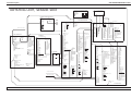
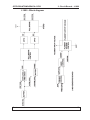
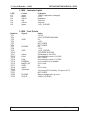
2.6 Wiring diagrams - overview
%2$5'3/$7(
833(56+(/)
0$,166:,7&+
$
/
1
%
1
3(
0$,16),/7(5
%
/
$
1
3(
3(
/2$'
/
/,1(
)86(6$
/
1
=0272575$1)250(5
3(
/=02725'5,9(5
-
$03)$6721
7$%&217$&7
$&
$&
-
$0302'8,,[0
(;36:
5($'</7
(;3/7
*1'
9
*1'
3&
$&
$&
%,B'$
%,B'$
%,B'%
%,B'&
%,B'&
%,B'%
%,B''
%,B''
='2:1
0,&52
6:,7&+
$&75287
$&75287
$&75287
-
$0302'8,,[0
=%27720
*1'
-
$0302'8,,[0
-
$0302'8,,[0
-
$0302'8,,[0
9
9
*1'
*1'
/,102725B+,&85
*1'
/,102725B&/.
*1'
/,102725B',5
/,102725B(1$
9
*1'
9
*1'
.(<67$7862.
63$5(287
63$5(287
63$5(,1
63$5(,1
*1'
=',5
=21
9
9
(6723
3/(1$
=(1$
.(<67$7862.
5(7851
0,55256:
=$&7
3/6:
(;36:
*1'
5($'</7
(;3/7
*1'
*1'
-
$03)$67217$%&217$&7
-
02/(;0,1,),7$
9
9
/,102725B6:
/,102725B6:
*1'
*1'
$&
$&
-
6,'(&21752/
3$1(/
6:,7&+(6
$0302'8,,[0
=83
(;36:
='2:1
5($'</7 -
=$&7,1
(;3/7
02/(;$ 3/,1
*1'
9$&
5(7,1
9
9$&
*1'
*1'
9$&
--
$0302'8,,[0
-
$0302'8,,[0
9
:$51,1*B/,*+7
6(79
9
6(79
:$51,1*B/,*+7
6(79
/,102725B+,&85
/,102725B6:
/,102725B6:
/,102725B&/.
/,102725B',5
-
/,102725B(1$
$0302'8,,[0
9
(6723B9
*1'
326/287
9
*1'
(6723B9
63$5(287
326/287
*1'
(6723B9
63$5(287
326/287
*1'
9
63$5(,1
(6723B9
*1'
63$5(,1
6,'(:$51,1*/,*+7
/$6(5
(0(5*(1&<
6:,7&+
-
$03)$67217$%&217$&7
$&
$&
%,B'$
%,B'$
%,B'%
%,B'&
%,B'&
%,B'%
%,B''
%,B''
5-
$&02725=029(0(17
-
$0302'8,[0
FDWHFRXSOHU
(;36:
*1'
-
$0302'8,,[0
=723
*1'
0
5-
-
-
$0302'8,,[0
06:
*1'
-
$03)$6721
7$%&217$&7
(7+(51(7
=83
0,&52
6:,7&+
-
5-
0ROH[
(;36:
5($'</7
(;3/7
*1'
9
*1'
-
$0302'8,,%;0
3(
-
5-
-
0ROH[
(;36:
(;7:$5
5($'</7
(;7:$5
(;3/7
;5$<21 &/26('
*1'
;5$<2))
23(1
9
*1'
FDWHFRXSOHU
(;32685(6:,7&+
(;7(51$/
/,*+76
/,17(5)$&(%2$5'
/$6(5
/$6(5
72)520527$7,1*81,7
22
Service manual
ORTHOPANTOMOGRAPH® OP30
2. Unit Description
527$7,1*81,778%(+($'6,'(
1
/2$'
/
/,1(
0$,16),/7(5
)520/%2$5'
/
1
3(
33)&%2$5'
-
02/(;$
-
02/(;$
/
1
-
02/(;$
17&
17&
*1'
*1'
$&B92/7$*(B021,725
32:(5*22'
212))
*1'
9
9
9
*1'
*1'
*1'
*1'
*1'
9
9
72/32:(56833/<%2$5'
-
$0302'8,,[0
9B+9*1'
+9*1'
-
-
02/(;$
02/(;$
9
9B+9*1'
+9*1'
9
9B+9*1'
+9*1'
/*(1(5$725%2$5'
;
02/(;$
9
*1'
*1'
78%(+($'$66(0%/<
;5D\7XEH
;
02/(;$
9
+9*1'
9B+9*1'
;
02/(;
78%()$,/
78%()$,/
(;3(1$
(;3(1$
.93:0
.93:0
*1'
*1'
.9)%
.9)%
*1'
*1'
35(+
35(+
0$3:0
0$3:0
0$)%
0$)%
78%(+($7
78%(+($7
72)520,17(5)$&(%2$5'
;
02/(;
&DVFDGH%RDUG
7XEHKHDGLQWHUIDFHERDUG
Service manual
;
02/(;$
+9
+9
.9)%
*1'
+($7&855(17
0$)%
P$;
NY;
35(+($7/,0,7
*1'
),/$0(1792/7$*(
),/$0(1792/7$*(
23
ORTHOPANTOMOGRAPH® OP30
2. Unit Description
527$7,1*81,76(16256,'(
/527$7,21326,7,216(1625
-
$0302'8,,%[0
9
5276:
5276:
*1'
/&'728&+6&5((1
23726(16256
3+$6(0,&5267(3'5,9(55
)52033)&%2$5'
-
$0302'8,,[0
9
*1'
9
*1'
3KDVH
3KDVH
3KDVH
67(33(5
02725
0
*1'
+,&85
*1'
&/.
*1'
',5
*1'
(1$
*1'
9
-
$0302'8,,[0
+,&85
*1'
&/.
*1'
',5
(1$
9'
*1'
/32:(56833/<
-
$0302'8,,[0
9
9
*1'
*1'
9
9
*1'
*1'
3,1+($'(5[
675$,*+7PP
-
02/(;$
9
9
*1'
*1'
*1'
9
$&92/7B021,725B)5(4
32:(5*22'
*1'
*1'
*1'
*1'
9B&&'
9B&&'
9B&&'
9B&&'
9B&&'
9B&&'
9B&&'
9B&&'
9B&&'
9B&&'
*1'
*1'
-
$0302'8,,[0
9
9
*1'
*1'
-
$0302'8,[0
9
*1'
9
*1'
-
$0302'8,,[0
9
*1'
9'B&&'
*1'
&&'(1$
$&92/7B021,725B92/7
32:(5*22'
&&'6(1625
&&'6(1625%2$5'
-
-
$0302'8,,[0
;
3,1+($'(5[
675$,*+7PP
*1'
*1'
'
'
'
'
'
'
*1'
*1'
+/
99
,0$*(
7',&/.
332:(5
*1'
*1'
'6
*1'
*1'
*1'
*1'
&5;'
&7;'
5(6(7QRWXVHG
;
3,1+($'(5[
675$,*+7PP
*1'
*1'
*1'
*1'
9B&&'
9B&&'
9B&&'
9B&&'
9B&&'
9B&&'
9B&&'
9B&&'
9B&&'
9B&&'
*1'
*1'
),/7(5%2$5'
;
*1'
*1'
*1'
9'B&&'3$1&$0'(7
9'B&&'3$1&$0'(7
;
9'B&&'
9'B&&'
*1'
*1'
*1'
*1'
-
$0302'8,,[0
/,17(5)$&(%2$5'
9
*1'
72)520/%2$5'
72)520/%2$5'
;
;
-
3,1+($'(5[
675$,*+7PP
*1'
*1'
'
'
'
'
'
'
*1'
*1'
+/
99
,0$*(B287
7',&/.B287
332:(5B287
*1'
*1'
'6
*1'
*1'
*1'
*1'
7;'B287
5;'
5(6(7B&&'QRWXVHG
*1'
*1'
*1'
9'B&&'
9'B&&'
9'B&&'
9'B&&'
*1'
*1'
*1'
*1'
-
02/(;$
9
9
*1'
*1'
-
5,%%21&$%/(PP
&$%/(&2'(
-
$0302'8,,[0
78%()$,/
78%()$,/
(;3(1$
(;3(1$
.93:0
.93:0
*1'
*1'
.9)%
.9)%
*1'
*1'
35(+B
35(+B
0$3:0
0$3:0
0$)%
0$)%
78%(+($7
78%(+($7
-
$0302'8,,[0
9'
5276:
5276:
*1'
-
$PS0RG%
6(79
6(79
6(79
/,102725B+,&85
/,102725B6:
/,102725B6:
/,102725B&/.
/,102725B',5
/,102725B(1$
9
*1'
9
*1'
63$5(287
*1'
63$5(287
0$)%
63$5(,1
*1'
63$5(,1
-
$0302'8,,[0
9'
9'
(6723
3/B(1$
=(1$
.(<67$7862.
5(7851
=$&7
3/6:
(;36:
*1'
5($'</7
(;3/7
*1'
*1'
-
9
9
*1'
*1'
-
-
-
6DPWHF
3,1+($'(5[
7)06':7
9
78%(+($7B287
9
*1'
*1'
/,102725B6: $&B92/7$*(B021,725
/,102725B6: *1'
0$)%B287
&+,/'B6(1625
%:B6(1625
.9)%B287
*1'
63$5(,1
*1'
63$5(,1
*1'
*1'
*1'
63$5(,1
*1'
63$5(,1
*1'
*1'
*1'
/,102725B+,&85 *1'
/,102725B(1$B *1'
*1'
9
/,102725B',5
9
/,102725B&/.B 9
*1'
9
&+,/'B&2//,0
9
%:B&2//,0
*1'
=(1$
63$5(287
5(6(7B&&'
63$5(287
3/B(1$
*1'
+,&85
*1'
63$5(287
9
6(79
6(79
6(79
-
5276:
3,1+($'(5[
5276:
9
5;'
*1'
0,62
99
*1'
.(<67$7862.
'6
(6723
*1'
=$&7
'
5(7851
'
78%()$,/
'
3/6:
'
+/
'
3/6:
'
+/
(;36:
*1'
026,
*1'
*1'
6&/.
*1'
&6
*1'
%((3
0$B5()
.9B5()
35(+
(;321
*1'
,0$*(
-
7',B&/.
7;'
$0302'8,,[0
&&'(1$
332:(5
9'
&/.B
*1'
*1'
9'B&&'
',5
*1'
*1'
5(*7(03
(1$B
&&'(1$
*1'
/,1(B2.
9
32:(5*22'
*1'
*1'
&.
+6<&
96<&
*1'
5
5
5
5
5
5
*1'
*
*
*
*
*
-$
-%
*
*1' -&
%
;
%
<
%
;
%
<
%
%
*1'
(1$%
9
9
5/
8'
*1'
-B&38
3,1+($'(5[
9
*1'
99
*1'
'6
*1'
'
'
'
'
'
'
QRWXVHG$'LQ
*1'
026,
*1'
6&/.
*1'
&6
*1'
%((3
0$B5()
.9B5()
35(+
(;321
*1'
,0$*(
QRWXVHG$'LQ
7',B&/.
7;'
&&'(1$
332:(5
&/.B
*1'
',5
*1'
(1$B
*1'
9
*1'
-
5-+6(
24
%,B'$
%,B'$
%,B'%
%,B'&
%,B'&
%,B'%
%,B''
%,B''
-RSWUH[
9
9
9
%/B(1$
%/B(1$
%/B(1$
-
*1'
/&'B6(/B
9B',63
9B',63
9B',63
9B',63
/&'B6(/B
/&'B6(/B
*1'
5*%
5*%
5*%
*1'
5*%
5*%
5*%
*1'
5*%
5*%
5*%
/'$%2$5'
-VKDUS
6+$53B/('
/('B*1'
6+$53B/('
/('B*1'
6+$53B/('
/('B*1'
6+$53B/('
/('B*1'
63,B0,62B,1
*1'
*1'
5*%
63,B6&/.B287
5*%
&6%
5*%
728&+B&6
*1'
',63B5(6(7B287
5*%
728&+B,54B,1
5*%
*1'
5*%
*1'
3:5B%71QRWXVHG
5*%
%71B67$57B,1QRWXVHG
5*%
%71BB,1QRWXVHG
5*%
%71BB,1QRWXVHG
*1'
%71BB,1QRWXVHG
96
%71BB,1QRWXVHG
+6
*1'
5*%B(1$B287 63$5(BB,1
*1'
63$5(
5*%B'&/.B287 67$57QRWXVHG
*1'
352;,0,7<QRWXVHG
63,B026,B287 *1'
-
-
6DPWHF
+LURVH
7)06':7 )+V6+
*1'
9
/&'B6(/B
9
9B',63
*1'
9B',63
*1'
/,102725B6: 9B',63
/,102725B6:
9B',63
/&'B6(/B
*1'
-
&+,/'B6(1625
/&'B6(/B
*1'
%:B6(1625
3,1+($'(5[
5*%
*1'
SLQLVQRWFRQQHFWHG
5*%
63$5(,1
78%(+($7B287
5*%
63$5(,1
SLQLVQRWFRQQHFWHG
*1'
*1'
QRWXVHG$'LQ
5*%
63$5(,1
SLQLVQRWFRQQHFWHG
5*%
$&B92/7$*(B021,725 63$5(,1
*1'
5*%
SLQLVQRWFRQQHFWHG
/,102725B+,&85 *1'
0$)%B287
/,102725B(1$B 5*%
SLQLVQRWFRQQHFWHG
5*%
*1'
.9)%B287
5*%
/,102725B',5
SLQLVQRWFRQQHFWHG
/,102725B&/.B *1'
*1'
5*%
*1'
*1'
5*%
&+,/'B&2//,0
*1'
5*%
%:B&2//,0
*1'
*1'
*1'
*1'
63$5(287
5*%
*1'
63$5(287
5*%
*1'
5*%
*1'
*1'
*1'
*1'
9
5*%
9
9
5*%
9
5*%
9
*1'
9
96
SLQLVQRWFRQQHFWHG
+6
=(1$
5*%B(1$B287
5(6(7B&&'
*1'
3/B(1$
5*%B'&/.B287
+,&85
*1'
63$5(287
63,B026,B287
6(79
63,B0,62B,1
6(79
*1'
6(79
63,B6&/.B287
5276:
&6%
5276:
728&+B&6
5;'
',63B5(6(7B287
0,62
728&+B,54B,1
'LVFRQQHFWHGWRWKLVSLQ
*1'
.(<67$7862.
3:5B%71QRWXVHG
(6723
%71B67$57B,1QRWXVHG
=$&7
%71BB,1QRWXVHG
5(7851
%71BB,1QRWXVHG
78%()$,/
%71BB,1QRWXVHG
3/6:
%71BB,1QRWXVHG
+/
*1'
3/6:
63$5(BB,1
+/
63$5(
(;36:
67$57QRWXVHG
352;,0,7<QRWXVHG
*1'
*1'
-
$0302',[0
9
*1'
/&38%2$5'
Service manual
ORTHOPANTOMOGRAPH® OP30
2. Unit Description
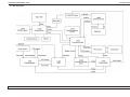
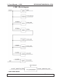
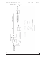
2.7 Block diagram
Service manual
25
2. Unit Description
ORTHOPANTOMOGRAPH® OP30
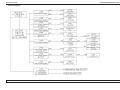
2.8 Fuse diagram
26
Service manual
ORTHOPANTOMOGRAPH® OP30
3. Circuit Boards - L900
3. Circuit Boards
NOTE: An asterisk (*) after a signal name indicates an active low-level signal.
3.1 L900, Display adapter
L900 - Location
In the rotating unit on the CCD sensor side.
To access remove sensor external cover.
Service manual
27
ORTHOPANTOMOGRAPH® OP30
3. Circuit Boards - L900
L900 - Field replaceable parts
None
L900 - Description
L900 is a display adapter/interface board that controls
the display (touch screen interface). L900 reads touch
screen data and sends it to L1200 CPU board via the
SPI interface. L1200 CPU board drives the display data
throught the L900 board.
L900 board produces supply voltages +3.3V for the
display and +15.8V for the display backlight.
L900 - Indicator LEDs
LED
H1
H2
H3
Colour
green
green
green
Indicates
3.3V OK
+15.8V OK
+5V OK
L900 - Test Points
None
28
Service manual
ORTHOPANTOMOGRAPH® OP30
3. Circuit Boards - L1200
3.2 L1200 CPU Board
L1200 - Location
In rotating unit on the CCD sensor side. To access remove the sensor external cover (see section 7.1).
L1200 - Field replaceable parts
None.
Service manual
29
ORTHOPANTOMOGRAPH® OP30
3. Circuit Boards - L1200
L1200 - Description
The CPU board controls the unit. It controls the rotation and Z movements, the operation of the X-ray tube
and reads the signals from the touch panel. It uses an
embedded microcontroller on an Altera Cyclone FPGA
circuit. The board also has an Ethernet transceiver (for
PC connection), I/O buffers, and a 14-bit A/D converter.
The image data are saved in an SDRAM.
L1200 - Indicator LEDs
LED
D6
D8
D9
D10
D11
D12
D13
D14
D20
D23
TEST1
TEST2
TEST3
Colour
green
green
green
green
green
green
green
green
green
green
green
green
green
Indicates
+5V on
Ethernet signal activity
10-Base-T (10Mbit/s) in use
100-Base-T (100MBit/s) in use
1000-Base-T (1000MBit/s) not supported
Full Duplex mode in use
+1.2V
+1.8V
+5V
+3.3V
Flashing = Core functioning
Flashing = Firmware functioning
Flashing = Not currently used
L1200 - Test Points
None
30
Service manual
ORTHOPANTOMOGRAPH® OP30
3. Circuit Boards - L1200
L1200 - Block Diagram
Service manual
31
ORTHOPANTOMOGRAPH® OP30
3. Circuit Boards - L1500
3.3 L1500, CCD Power Supply
L1500 - Location
In the rotating unit on the the CCD sensor side.
To access remove sensor external cover.
L1500 - Field replaceable parts
None.
32
Service manual
ORTHOPANTOMOGRAPH® OP30
3. Circuit Boards - L1500
L1500 - Description
L1500 supplies different voltages to most of the circuit
boards in the unit. L1500 receives +27V5 and -20V from
P1910 PFC and regulates these voltages to produce
the other voltages that the unit requires.
The CCD sensor require +3.3V, +3.3V, +3V, +15V,
-9.4V, +5V.
L900 and the 3-phase stepper motor require 24V.
L1200 and peripheral electronics require a regulated
5VDC power supply.
P1910 measures mains voltage. This value is converted
to frequency signal and is then transferred to L1500
board. On L1500 board the signal is converted to DC
voltage. This DC voltage is measured by AD-converters
on L1200 CPU board.
Service manual
33
3. Circuit Boards - L1500
ORTHOPANTOMOGRAPH® OP30
L1500 - Block diagram
34
Service manual
ORTHOPANTOMOGRAPH® OP30
3. Circuit Boards - L1500
L1500 - Indicator LEDs
LED
D8
D9
D10
D12
D13
D14
D16
D17
Colour
green
green
green
green
green
green
green
green
Indicates
+15V_CCD on
+3.0V_CCD on
+3.3V_CCD on
+5V on
+5.0V_CCD on
-9.4V_CCD on
+24V on
+3.3V on
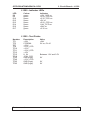
L1500 - Test Points
Number
TP1
TP5
TP7
TP8
TP10
TP11
TP12
TP15
TP18
TP25
TP40
TP65
TP65
Description
+24V
CCDENA
+5.0V
+5.0V_CCD
+3.3V
+3.0V_CCD
+15V
U_IN
-9.4V_CCD
GND (logic)
+3.3V_CCD
GND (logic)
GND (logic)
Service manual
Value
+24V
5V on, 0V off
Between 1.3V and 3.5V
0V
0V
0V
35
ORTHOPANTOMOGRAPH® OP30
3. Circuit Board - L1600
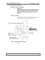
3.4 L1600, Z-Motor Driver
L1600 - Location
On the upper shelf.
To access remove shelf upper cover (see section 7.1).
36
Service manual
ORTHOPANTOMOGRAPH® OP30
3. Circuit Boards - L1600
L1600 - Field replaceable parts
NOTE:
The fuses used MUST be the approved type, UL listed
and CSA certified.
Approved fuses:
Fuse F1
2AT/250VAC Cooper Bussmann MDL-2
2AT/250VAC Littelfuse 0313002 HXP
Fuse F2
8AF/250V Littelfuse 0312008 312 series
8AF/250V Cooper Bussman AGE
Dimensions 6.3 mm x 32 mm.
L1600 - Description
L1600 (Z-Motor Driver) controls the AC-motor that
drives the unit up and down. Membrane switches on
the side of the vertical carriage are used to activate the
AC-motor.
Micro switches at the top and bottom of the column
monitor the upper and lower positions of the Z-movement. Based on the logic on the circuit board, the movement of the AC motor is enabled or prohibited. Three
triacs control the Z-motor currents. Outputs are optocoupled from the user inputs with TLP3063 circuits. The
board also includes light controls for the laser positioning lights.
L1600 also sets the autotransformer input winding.
There are three SET signals, SET 100V, SET 115V and
SET 230V that control what mains voltage goes to what
input winding of the autotransformer.
The auto transformer output voltage is always 230 VAC
Service manual
37
3. Circuit Board - L1600
ORTHOPANTOMOGRAPH® OP30
L1600 - Block diagram
38
Service manual
ORTHOPANTOMOGRAPH® OP30
3. Circuit Boards - L1600
L1600 - Indicator lamp
Lamp
LA1 GLIM
Function
AC indicator lamp
Indicates
L1600 receiving line voltage.
L1600 - Indicator LEDs
LED
D1
D2
D3
D4
D5
Colour
green
green
green
red
green
D6
green
D7
green
Indicates
+5V on
ZACT-movement key pressed
ZON on
ESTOP on. Emergency stop button is on.
SET 100V: autotransformer tapping 100V
enabled
SET 115V: autotransformer tapping 115V
enabled
SET 230V: autotransformer tapping 230V
enabled
L1600 - Test Points
Number
TP1
Signal
ESTOP_5V
TP2
TP3
TP4
TP5
TP6
ZDIR
ZON
+5V
GND
ZACT*
Service manual
Value
+5V normally, 0 ... +0.5V when emergency
button pressed down
0V driving up, +4.8V...+5V driving down
+3V when up/down key pressed, 0V when not.
+5V
0V
0 ... +0.5 when up/down key pressed,
otherwise close to +5V.
39
ORTHOPANTOMOGRAPH® OP30
3. Circuit Boards - L1700
3.5 L1700 Connector Board
L1700 - Location
In the rotating unit on the the CCD sensor side.
To access remove sensor external cover.
L1700 - Field replaceable parts
None.
40
Service manual
ORTHOPANTOMOGRAPH® OP30
3. Circuit Boards - L1700
L1700 - Description
L1700 routes most of the signals to the other boards.
L1700 receives signals from the tubehead (kVfb, mafb,
and tubeheat) and scales the voltage swing (0…+5V)
linearly to (1.25V…3.75 V) which is the input for the
A/D converter on the CPU board. L1700 also includes
external warning and ready light circuitry. The ESTOP
signal enables stepper motor rotation and the exposure
sequence.
L1700 - Indicator LEDs
None.
L1700 - Test Points
Number
TP1
TP2
Description
GND
GND
Service manual
Value
0V
0V
41
3. Circuit Boards - L1700
ORTHOPANTOMOGRAPH® OP30
L1700 - Block Diagram
42
Service manual
ORTHOPANTOMOGRAPH® OP30
3. Circuit Boards - L1800
3.6 L1800, Generator Board
DANGER: HIGH VOLTAGE
WARNING:
Do not touch the Generator Board until the capacitors have discharged. After switching the unit off
wait 10 minutes for the capacitors to discharge.
When LED H1 goes out the capacitors are discharged.
L1800 - Location
In rotating unit on the tubehead side. To access remove
the tubehead external cover (see section 7.1).
L1800 - Field replaceable parts
None
Service manual
43
ORTHOPANTOMOGRAPH® OP30
3. Circuit Boards - L1800
L1800 - Description
The Generator board receives kV and mA reference
signals from L1200 as PWM modulated signal. Based
on the kV-reference value, the Generator board generates the corresponding high voltage between the cathode and anode of the x-ray tube. Based on milliampere
reference value, the generator board generates preheat current (to warm up the filament before x-rays are
switched on) and filament current (during exposure).
The Generator board receives kV and mA feedback
signals from the tubehead that are used to monitor and
adjust the generated values. The Generator board produces its own supply voltages.
44
Service manual
ORTHOPANTOMOGRAPH® OP30
3. Circuit Boards - L1800
L1800 - Block diagram
Service manual
45
ORTHOPANTOMOGRAPH® OP30
3. Circuit Boards - L1800
L1800 - Indicator lights
LED
H1
H2
H3
H4
H5
H6
Colour
green
green
yellow
red
yellow
green
Indicates
+380V (capacitors charged)
+15V
Exposure
Tube fail
Preheat
+15V_HVGND
L1800 - Test Points
Number
TP1
TP2
TP3
TP4
TP5
TP6
TP7
TP8
TP9
TP10
TP11
TP12
TP13
TP14
TP15
TP16
TP17
TP18
TP19
TP20
TP21
TP22
TP23
46
Signal
GND
HVGND
VDD
mAref
kVref
kVfb
EXPENA
MAFB_INT
GND
mAfb
Tubeheat
HVGND
HV310
Value
+27V5
+5V FILTERED MAPWM
0V
+15V
NOT USED
NOT USED
0V
+17V
+15V_HVGND
FILTERED KVPWM
Calibrated by the CPU
Counted from value 1V=22kV
NOT USED
Counted from value 1V=22kV
on to enable off to disable
0.2V=1mA
0V
0.2V=1mA
J2 closed=25V (default); J2 open=20.7V
NOT USED
Mains voltage side, ground
+380V (HVGND)
Service manual
ORTHOPANTOMOGRAPH® OP30
3. Circuit Boards - P1910
3.7 P1910, PFC Board
P1910 - Location
DANGER: High voltage on this board.
Do not touch this board when the unit is switched
on.
There is high voltage on the large heat sink on this
board when the unit is switched on.
Do not touch this board until the capacitors have
discharged. After switching the unit off wait 10 minutes for the capacitors to discharge.
P1910 - Field replaceable parts
Fuse FH2: SIBA FF6.3A 70 125 40. 6.3A
Service manual
47
ORTHOPANTOMOGRAPH® OP30
3. Circuit Boards - P1910
P1910 - Description
The P1910 PFC (Power Factor Correction) power supply board generates the supply voltages for the unit.
This board works with mains voltages between 100VAC
to 240VAC, 50/60Hz.
The board produces the +380Vdc for the generator
board. The board also has auxiliary flyback converter
that produces the lower raw voltages for the L1500
power supply board.
The major features of the board:
48
-
the supply voltages do not depend on the line voltage (PFC)
-
it supplies voltages +380VDC and +17VDC (against
HVGND)
-
it supplies voltages +27.5VDC, -15VDC and
-20VDC (against GND)
-
it monitors the line voltage (FMON) and PFC middle
circuit voltage (PWR_OK)
Service manual
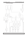
ORTHOPANTOMOGRAPH® OP30
3. Circuit Boards - P1910
P1910 - Block diagram
Service manual
49
ORTHOPANTOMOGRAPH® OP30
3. Circuit Boards - P1910
P1910 - Indicator LEDs
LED
A5
A8
A9
A10
A15
Colour
green
green
green
green
green
Indicates
+380V
+27V5
+20V
17V_HVGND
-15V
P1910 - Test Points
None
50
Service manual
ORTHOPANTOMOGRAPH® OP30
3. Circuit Boards - L1300
3.8 L1300 Interface Board
L1300 - Location
At the rear of the column near the base.
L1300 - Field replaceable parts
None.
L1300 - Description
L1300 serves as an external interface to the outside
environment. The exposure button and the remote exposure button are connected to this board.
L1300 - Indicator LEDs
None.
L1300 - Test Points
None.
Service manual
51
ORTHOPANTOMOGRAPH® OP30
3. Circuit Boards - L2100
3.9 L2100 Rotation Position Sensor Board
L2100 - Location
Inside the rotating unit under the head support. To
access, remove the head support and then the lower
protective cover (see section 7.1).
L2100 - Field replaceable parts
None.
L2100 - Description
L2100 is used to detect the position of the rotating unit.
L2100 has two optical switches that generate sensor
signals ROTSW1 and ROTSW2 according to which
position is activated.
L2100 includes a transmitter LED, and a receiver, or
base. The sensor signals remain on as long as the base
receives light from the LED. When the light to the base
is cut off by the positioning rail, the sensor signal is
switched off.
52
Service manual
ORTHOPANTOMOGRAPH® OP30
3. Circuit Boards - L2100
L2100 - Indicator LEDs
None.
L2100 - Test Points
None.
Service manual
53
3. Circuit Boards - R5100
ORTHOPANTOMOGRAPH® OP30
3.10 R5100, 3-Phase Microstepper Driver
R5100 - Location
Inside the rotating unit, above the head support. To access, remove the head support, lower protective cover
(see section 7.1).
R5100 - Field replaceable parts
None.
R5100 - Description
R5100 controls the 3-phase stepper motor that drives
the Rotating Unit. The board receives in three control
signals: clk, dir, and ena. It produces phase voltages for
the stepper motor windings.
54
Service manual
ORTHOPANTOMOGRAPH® OP30
3. Circuit Boards - R5100
R5100 - Indicator LEDs
LED
D1
D2
Colour
green
green
Indicates
+5V on
+24V on
R5100 - Test Points
Number
TP1
TP2
Description
GND
VREF
TP3
TP4
TP5
CLK
ENA
DIR
TP6
PGND
Service manual
Value
0V
0.97V ±0.1V; when HICUR* = '1'
1.95V ±0.1V; when HICUR* = '0' (default value)
+5V freq <15kHz
+5V active, 0V idle
+5V when idle or when moving to the
PIO position.
0V when driving to end position.
0V
55
3. Circuit Boards - CCD Sensor / Filter
ORTHOPANTOMOGRAPH® OP30
3.11 CCD Sensor / Filter board
CCD / Filter - Location
In rotating unit. To access, remove the sensor inner
cover (see section 7.1).
CCD - Field replaceable parts
None. Inside the CCD Sensor there is the CCD Sensor
board. The board cannot be accessed.
CCD - Description
CCD sensor converts X-ray radiation to visible light and
and then the CCD semiconductor chips measure the
intensity of the visible light. The analog signal is A/Dconverted and sent in parallel data lines to the CPU
board.
56
Service manual
ORTHOPANTOMOGRAPH® OP30
3. Circuit Boards - CCD Sensor / Filter
CCD - Indicator lights
Remove the covers from the CCD side of the rotating
unit On the rear of the CCD sensor there are a number
of LEDs that indicate the status of the CCD sensor.
LED
Power
Colour
Yellow
Indicates
Indicates that the power signal is active.
Image
Yellow
Indicates image signal activity. It tells the CCD sensor
A/D-converter to sample image data according to the
TDI frequency.
TDI Clk
Yellow
Indicates that the clocking frequency of the CCD is
available.
TDI frequency is between 0...50Hz.
TDI frequency is between 100 Hz...1kHz.
TDI frequency is between 50...100Hz or above 1kHz.
Off
On
Flashing
Power Supply
Indicate the different voltages required by the CCD
sensor. The microcontroller in the CCD sensor monitors
the voltages and activates the LEDs accordingly.
There are software set limits for the various supply
voltages. The LEDs come on during image capture.
1
Yellow
+3.3V and +1.8V LEDs
Supply voltages for the CCD clock controlling FPGA.
The +3.3V is generated by L1500.
The +1.8V step down is generated in CCD sensor
board from +3.3V.
LIMITS:
+3.3V between +3.0 and +3.6V.
+1.8V between +1.71V and +1.89V.
2
Yellow
Analog +5V LED.
Supply voltage for AD-converters.
LIMITS:
between +4.5V and +5.5V
Service manual
57
3. Circuit Boards - CCD Sensor / Filter
3
Yellow
ORTHOPANTOMOGRAPH® OP30
+15V, +3V and –9.4V LED
CCD gate voltages
LIMITS:
+15V between +13.5V to +16.5V
+3V between +2.4V and +3.6V
-9V between -9.92V and -9.17V
Another required voltage is μC +3.3V. It is used to
power the microcontroller, +3.3VD_CCD.
CCD TxD and CCD RxD
Yellow
Serial communication.
In normal operation they flash intermittently.
They indicate communication activity.
If CCD RxD is off (passive CCD sensor), CCD TxD
will also be off.
NOTE:
If CCD TxD is off, CCD RxD is on and
the CCD status LED flashes during and after image
capture it indicates that the CCD sensor tried to
receive the image, but the transmit communication
routine failed.
CCD Status 3-color
It indicates that the CCD is connected, all the software
has been downloaded and it is ready to take an image.
Green
Stand-by mode.
Yellow
Image capture mode (power on).
Red
In position but not yet ready, SW is being loaded.
Red flashing
Fatal SW error / communication routine failure after
an image has been taken.
If this happens, switch the unit off for 10 seconds and
then switch the unit on again.
58
Service manual
ORTHOPANTOMOGRAPH® OP30
3. Circuit Boards - CCD Sensor / Filter
Filter - Field replaceable parts
None.
Filter - Description
Sensor filter board is a low pass type RF-filter board
which filters electromagnetic interference (EMI) from all
CCD-signal and and power supply lines.
Filter - Test Points
None.
Service manual
59
ORTHOPANTOMOGRAPH® OP30
4. Troubleshooting
4. Troubleshooting
4.1 Initial checks
Restarting the unit
If the unit fails to operate, does not operate correctly or
if an error code appears, switch the unit off, wait for a
few seconds and then switch the unit on again. If the
unit still does not operate correctly or the error message
reappears, follow the troubleshooting procedures described here to correct the problem.
If there is a problem with image transfer, close and reopen the dental imaging software and/or restart the PC.
Error Codes
If the unit malfunctions or if it is used incorrectly an error
code will appear on the main control panel.
There are two categories of error code:
-
H, user errors, and
-
E, system errors.
When an error code appears on the display the unit will
stop working. The unit cannot be operated while the error code is on the display.
To clear an error code from the display, correct the error
and then press any key on the main control panel (NOT
the side control panel).
NOTE:
Error E18, display failure can only be seen on the service assistant.
Checking circuit boards
Circuit boards cannot be repaired in the field. On some
boards some fuses can be replaced. But, if a board is
faulty, replace it.
On most of the circuit boards there are indicator LEDs,
that allow the operation of the board to be monitored,
and test pins (TP), that allow the operation of the board
to be checked. LED and test pin descriptions for each
circuit board are in the section 3 Circuit Boards.
Use a digital multimeter (DMM) when checking boards.
60
Service manual
ORTHOPANTOMOGRAPH® OP30
4. Troubleshooting
Checking cables and connectors
Visually check cables for mechanical damage, cuts,
damaged insulation and twists. If a cable is damaged in
any way replace it.
If there is no obvious mechanical damage to a cable but
you think that it may be faulty, use a digital multimeter
(DMM) to check the resistance of the different wires
within the cable. An undamaged wire will have close
to no resistance (>0 ohm), a damaged wire will have a
high resistance value.
Make sure that all cables are correctly and securely attached to their respective connectors. Connectors must
not be loose or misaligned. If the connector has a locking mechanism make sure that it is locked.
If you find a loose or misaligned connector, disconnect
it and check for bent, broken or missing pins. If there
is damage that can be easily repaired, for example
straightening a bent pin, repair the damage and reconnect the connector. If the damage cannot be repaired
replace the cable.
Note that if the connector on the board is also damaged, the board may also have to be replaced.
Power supply problems
Power supply problems are described in section - 4.2
Problems during start up.
Service manual
61
ORTHOPANTOMOGRAPH® OP30
4. Troubleshooting
4.2 Problems during start up
Nothing happens when the unit is switched on
The on/off switch light does not come on.
CAUSE A
Power cut.
SOLUTION A
Check to see if the power has been cut off.
CAUSE B
Unit not connected to the main power supply
SOLUTION B
Make sure that the unit is connected to the main power
supply. Check the condition of the power supply cable.
If it is damaged, replace it.
CAUSE C
The main fuses (2) have blown.
SOLUTION C
Disconnect the main power supply cable from the unit
and then replace the main fuses (2). They are located
below the main power supply cable at the rear of the
column.
The fuse ratings are stated in chapter 2.5 Electrical
description - Main fuses.
The on/off switch light comes on but the display
does not come on.
CAUSE A
L900 (Control panel) is not receiving power or is faulty.
SOLUTION A
Check the supply of power to L900. Power is routed to
L900 as follows:
1. Mains power is supplied to L1600 (Z-Motor Driver.
If L1600 is receiving power lamp LA1 (on L1600)
will be on.
If it is not, check the cables and connectors between the on/off switch and L1600 (J105 and J106)
and replace the cables if they are faulty.
If the cables are okay, replace L1600.
62
Service manual
ORTHOPANTOMOGRAPH® OP30
4. Troubleshooting
2. L1600 (Z-motor driver) supplies mains voltage to
the P1910 (FPC board) via a filter.
Check that LEDs
A5 = +380V,
A8 = 27V5,
A9 = -20V,
A10 = +17V
and A15 = -15V on P1910 are on.
If they are not on check fuse FH2, and replace if
blown.
If the fuse is not blown check and if necessary replace the cables between L1600 and the filter and
between the filter and P1910.
If the LEDs on P1910 still remain off, replace
P1910.
If the P1910 LEDs are on but the display is not
working, check the LEDs on L1500 (Power Supply
Board). LED:
D8 = +15V on when CCDENA is active
D9 = +3V on when CCDENA is active
D10 = +3.3VD on when CCDENA is active
D12 = +5V, must be on
D13 = +5V on when CCDENA is active
D14 = -9.9V on when CCDENA is active
D16 = +24V, must be on
D17 = +3.3V, must be on
Test jumper J23 can be used to set on CCDENA;
Open=default, closed=CCDENA enabled
If the LEDs do do not function as described above,
check the cable between P1910 and L1500. Replace if faulty.
3. L1500 supplies 24V to L900. At normal state, the
leds burn when 24V voltage is connected to L900.
H1 is +3.3V indicator led, touch controller ic powered with +3.3V. H2 is +15.8V indicator led for LCD
backlight voltage(OPTREX T-55265GD057J-LWCAN not default).
Check that LED H1 is on (green). Check that LED
H2 is on (green). If LEDs H1 and H2 are not on
replace L900.
H3 is on (green) as the +5V comes from L1200
(CPU board).
4. Check the cables between L900 and the LCD-display. If the cables are okay, replace LCD-display.
Check the cable between L900 and L1200, replace
if faulty.
Service manual
63
ORTHOPANTOMOGRAPH® OP30
4. Troubleshooting
CAUSE B
The display backlight power level has been set to OFF.
SOLUTION B
Use the service terminal to change the display backlight
power level.
Error E3 (CFG Data lost)
CAUSE
L1200, CPU board, has lost the calibration data and
settings.
SOLUTION
Recalibrate L1200, see 5. Service Assistant and Service Functions.
The required calibrations are:
- IP address will default, must be reset if another address is required (see installation manual)
- tubehead calibration: service command "calib"
- line voltage calibration
- set the serial number
If the error message reappears after recalibration,
L1200 is faulty. Replace, see 7.5 Replacing circuit
boards.
Error E5 (Line voltage out of limits)
CAUSE A
Line voltage to high or low.
SOLUTION A
The error code will clear automatically when the voltage
returns to its normal level.
If the voltage is not stable where the unit is being used,
you may have to instal a voltage stabilizer.
CAUSE B
Line voltage has not been calibrated.
SOLUTION B
Calibrate the line voltage.
CAUSE C
Faulty cable(s).
SOLUTION C
Check cables and connections between
P1910 and L1500
L1500 and L1700
L1700 and L1200.
Replace any faulty cables or boards with faulty connectors.
64
Service manual
ORTHOPANTOMOGRAPH® OP30
4. Troubleshooting
Error E8 (File system failure)
CAUSE
GUI graphics are corrupted.
SOLUTION
Update the GUI graphics.
Error E16 (Z lift not allowed due to duty cycle)
CAUSE
Z-motor over heated.
SOLUTION
Allow motor to cool down.
Error E18 (Display not connected)
Check Service Assistant for information about this
error code
CAUSE A
Cable from L1500 to L900 faulty.
SOLUTION A
Replace cable.
CAUSE B
L1500 faulty.
SOLUTION B
Replace L1500.
CAUSE C
Cable between L1200 and L900 faulty.
SOLUTION C
Replace cable.
CAUSE D
Cable between L900 and LCD display faulty.
SOLUTION D
Replace cable.
CAUSE E
L900 faulty.
SOLUTION E
Replace L900.
CAUSE F
LCD display is faulty.
SOLUTION E
Replace LCD display.
Service manual
65
ORTHOPANTOMOGRAPH® OP30
4. Troubleshooting
Error E19 (Exposure switch stuck down)
CAUSE
Exposure switch stuck down during unit start up.
SOLUTION
Switch the unit off and check that the exposure switch
is not stuck in the exposure position. Switch the unit on
again. If the message reappears, the switch is faulty,
replace.
Error E20 (PCF: POWERGOOD signal is down)
CAUSE
No power signal.
SOLUTION
Check to see if the signal is present on L1500.
If the signal is not present, replace P1910.
If signal is present, the fault could be in the signal routing. Check signal on L1500, L1700 and L1200 and in
the relevant cables. Replace any faulty boards or cables.
Error E22 (Button stuck)
Appears only on start-up
CAUSE
The membrane switches on the column are stuck.
SOLUTION
Reboot, if problem persists, replace the membrane buttons.
66
Service manual
ORTHOPANTOMOGRAPH® OP30
4. Troubleshooting
4.3 Problems while preparing the unit for an exposure
Image of emergency button appears on main display
CAUSE
The emergency switch has been pressed down.
NOTE: LED D4 (ESTOP on) on L1600 will come on
when the emergency switch is pressed down.
SOLUTION
Turn the emergency switch clockwise to release it.
The side control panel Return key does not work
CAUSE
The Membrane key panel is faulty.
SOLUTION
Press some of the other keys to see if they work correctly. If they do it indicates that the return membrane
key is faulty and the membrane key panel must be
replaced.
Error E 7 (Opto or r-motor failed during r-movement)
CAUSE
L2100 or R5100 or rotating unit stepper motor is faulty.
The rotating unit cannot position itself correctly and
keeps on rotating, until the timeout (E 9) stops movement, because L2100 is faulty.
The rotating unit does not move when the R key is
pressed.
SOLUTION
L2100 can be checked by using the service command
"optotest", see section Service Assistant and Service
Functions.
The optotest command displays values that indicate
the position of L2100. When you manually rotate the
rotating unit the values should change, sector 0, sector
1, sector 2 and sector 3, which indicates that the optosensors on the board are working and that L2100 is
functioning correctly.
If the values do not change, L2100 or the cable from
L1700 to L2100 is defective.
If L2100 is functioning correctly it indicates that there is
a problem with the stepper motor.
Check if R5100, the stepper motor or cable from R5100
to the stepper motor are faulty. Replace any that are.
Service manual
67
4. Troubleshooting
ORTHOPANTOMOGRAPH® OP30
Rotating unit stop rotating, no error code
CAUSE A
Faulty R5100 or stepper motor.
SOLUTION A
Check the cables connected to R5100. If ok, replace
R5100.
If the unit still does not work, replace the stepper motor.
Patient positioning light(s) do not come on
The patient positioning lights (lasers) come on when:
- the light key is pressed
- or the up or down key is pressed
One of lights does not come on.
CAUSE A
The light is faulty.
SOLUTION A
Check the cable and connector from the L1600 (Zmotor driver) to the light and replace the cable and light
if faulty.
Realign the light, refer to the installation manual.
If the cable is okay replace the L1600 (Z-motor driver).
None of the lights come on.
CAUSE A
The emergency stop button has been pressed down.
The emergency stop icon appears on main display.
NOTE: LED D4 (ESTOP on) on L1600 will come on
when the emergency switch is pressed down.
SOLUTION A
Turn the emergency switch clockwise to release it.
CAUSE B
The emergency stop icon appears on the main display
but does not clear when the emergency stop button is
released. The patient positioning lasers do not come
on.
SOLUTION B
Check connector JP129 on L1600 (Z-motor driver).
Check cable between L1600 and the emergency stop
button.
NOTE:
When LED D1, on L1600 (Z-motor driver), is on it indicates that the board is receiving 5VDC from L1500
(CCD power supply). If the LED D1 is not on there is a
power supply problem.
68
Service manual
ORTHOPANTOMOGRAPH® OP30
4. Troubleshooting
CAUSE C (Unlikely)
All the lights are faulty.
SOLUTION C
Replace all the lights, they are connected to L1600 (Zmotor driver) and then realign them. Refer to the installation manual.
Up/down (Z-motor) keys do not work
CAUSE A
The emergency switch has been pressed down.
Image of emergency button appears on main display.
NOTE: LED D4 (ESTOP on) on L1600 will come on
when the emergency switch is pressed down.
SOLUTION A
Turn the emergency switch clockwise to release it.
CAUSE B
Z-motor not receiving power.
SOLUTION B
Check to see if lamp LA1 and LED D1 on L1600 are on.
If they are not then check fuses F1 and F2. Replace if
blown.
If after replacing fuse F2 lamp LA1 comes on but LED
D1 still does not come on,check cables between L1600
and L1700. If the cables are OK, check if D12 is on on
L1500. If it's not, replace L1500.
If LA1 and D1 are on check the cable from L1600
(J104) to the Z-motor. Replace if faulty.
If the cable is not faulty measure the AC voltage from
the Z-motor connector, on L1600, to the Z-motor. Press
the UP/DOWN key and check that there is an AC-voltage.
Note that you need to connect the DMM differently
when running the unit in the Up direction and in the
Down direction.
If no voltage can be measured, replace L1600.
If there is voltage but the Z-motor does not operate,
replace the Z-motor.
Check the autotransformer connection.
Make sure that only one of the primary windings is connected.
D5 = SET 100V
D6 = SET 115V
D7 = SET 230V
Service manual
69
4. Troubleshooting
ORTHOPANTOMOGRAPH® OP30
CAUSE C
The side control panel (up/down keys) has failed
SOLUTION C
If D2 and D3 on L1600 do not come on when the up/
down keys are pressed it indictes that the side control
panel or the cable from the control panel are faulty and
must be replaced.
CAUSE D (Unlikely)
The Z-movement end microswitch (top or bottom has
failed) and the mechanical Z-movement end stops have
stopped the Z-carriage.
SOLUTION D
Check to see if D3 on L1600 is on. If on it indicates that
the top or bottom Z-movement end microswitch has not
been activated.
CAUSE E
The autotransformer internal thermal switch has
opened. The thermal switch will open if the winding
temperature goes over 110°C.
SOLUTION E
There is a probably a short circuit inside the transformer
winding that has caused it to overheat.
Replace the transformer.
CAUSE F
The Z-motor internal thermal switch has opened. If the
unit is driven up and down for a long period time the
Z-motor can overheat and cause the thermal switch to
open.
SOLUTION F
Wait for the Z-motor to cool down and the thermal
switch to close.
70
Service manual
ORTHOPANTOMOGRAPH® OP30
4. Troubleshooting
4.4 Problems during exposure
Nothing happens when the exposure button is pressed
CAUSE A
Exposure switch failed.
SOLUTION A
Replace the exposure switch.
CAUSE B
Unit not in ready mode,no PC-connection or no active
client reserving the unit.
SOLUTION B
Check PC connection and SW status.
CAUSE C
Faulty cable(s) between L1300 (Interface board) and
L1600 (Z-motor driver), or between L1600 and L1700
(Connector board), or between L1700 and L1200
(CPU board), or between L1700 and L1800 (Generator
board).
SOLUTION C
Replace faulty cable(s).
Error code H1 (Exposure interupted)
CAUSE A
OPERATOR ERROR. The exposure button was released during an exposure.
SOLUTION A
Advise the operator to hold down the exposure button
for the duration of the exposure.
CAUSE B
The exposure button failed while it was being pressed
during an exposure.
SOLUTION B
Take a test exposure to see if the same error code appears again. If it does, replace the exposure button.
Service manual
71
ORTHOPANTOMOGRAPH® OP30
4. Troubleshooting
Error codes E0, E1 and E2
NOTE:
Error codes E0, E1, E2 all indicate that the tubehead
and/or Generator board are not functioning correctly.
E0 (Tube arcing)
CAUSE
Tube arcing.
NOTE:
Check the tube fail LED (red) in the upper right corner
of the Generator board. If it is on it indicates that the
tube is arcing.
E1 (tubehead voltage)
CAUSE
Tubehead voltage (kV) out of limits.
E2 (tubehead current)
CAUSE
Tubehead current (mA) out of limits.
SOLUTION
Use the S2terminalt to check the mA and kV feedback
signals from the tubehead to see if the tube voltage and
current are correct (Software Check).
See S2terminal and service functions.
If the feedback values are not correct use the exp service function to measure and compare the values (Refer to Service Assistant and Service functions in section
5).
Select an exposure time of 2000 ms (2 seconds) or
greater so that the mAfb and kVfb ADC values can be
measured.
CAUTION:
Protect yourself from radiation when carrying out
this procedure.
Press and hold down the exposure button. The "actual"
mAfb and kVfb ADC values will appear on the display
next to "target" values.
If the "actual" values differ by less that ±2kV from the
target values, the tubehead is working correctly.
72
Service manual
ORTHOPANTOMOGRAPH® OP30
4. Troubleshooting
If the "actual" values differ by more than ±2kV from the
target values, it indicates that there is a problem and
the tubehead must be recalibrated.
From the Service Assistant select calib and calibrate
the tubehead.
NOTE:
Keep exposure switch pressed for the duration of the
calibration program.
After recalibrating the tubehead check if the calibration
was successful.
If the calibration is successful select the exp function
again and confirm that the mA and kV feedback signals
are correct.
If the calibration was unsuccessful and the unit still
does not work correctly, check the hardware.
Hardware check
Remove the cables from the tubehead side of the rotating unit. Check the cables between the Tubehead and
the Generator board. Replace them if they are faulty
and then recalibrate (calib) the tubehead.
If recalibration is not sucessful, measure the feedback
signals from the L1800 Generator board. From the Service Assistant select exp.
Connect a DMM to the TP14 (kVfb) and TP17 (GND) on
the Generator board and take an expose.
Then connect the DMM to TP18 (mAfb) and TP17
(GND) and take another exposure.
The values for feedback signals can be counted as described in chapter 3.6 L1800, Generator Board - Test
points
If values for the feedback signals are not within the limits, and recalibration does not help, measure the reference signals from L1800 Generator board.
Service manual
73
4. Troubleshooting
ORTHOPANTOMOGRAPH® OP30
Connect a DMM to TP12 (kVref) and TP17 (GND) on
L1800 and take an exposure.
Then connect the DMM to TP11 (mAref) and TP17
(GND) and take another exposure.
The values for feedback signals can be counted as described in chapter 3.6 L1800, Generator Board - Test
points
If the reference values are correct, but feed back values
are not, the Tubehead and/or the Generator board may
be faulty and must be replaced.
If there are no reference signals check the cabling between the L1800 Generator board and L1700. Replace
if faulty.
Error E10 (CCD initialization/configuration failure)
CAUSE
There is no serial bus connection or the CCD sensor
could not configure itself.
SOLUTION
Check the condition of all the cables and connectors to/
from the CCD sensor as well as the cables from CPU
to L1700 and cables between L1700 and L1500. Check
that none of the fuses on L1500 have blown.
Check that CCD filter board is mounted correctly and
cables are properly connected. If the problem still
exists, replace sensor.
Error E11 (CCD power failure)
CAUSE
Supply voltages to the CCD sensor were not within tolerances during imaging.
SOLUTION
Check the condition of all the cables and connectors to/
from the CCD sensor.
Check the voltages on L1500 by checking the reference LEDs. Always measure the voltages from the test
points. Note that the voltages are only enabled during
an exposure. To enable the CCD voltages without taking an exposure, connect a jumper to J23. Remove the
the jumper after taking measurements.
74
Service manual
ORTHOPANTOMOGRAPH® OP30
4. Troubleshooting
Error E12 (CCD line failure)
CAUSE
The image data flow from the CCD sensor to L1200
was interrupted during the exposure.
SOLUTION
Refer to the trouble shooting information given in error
code E11.
Error E13 (CCD Configuration checksum failure)
CAUSE
L1200 CPU failed to read CCD configuration parameters.
SOLUTION
Reboot the unit. If the problem persists, change the
CCD sensor.
Service manual
75
ORTHOPANTOMOGRAPH® OP30
4. Troubleshooting
4.5 Problems after exposure
Error E4 (Tubehead too hot)
CAUSE A
The tube head has overheated (> 55°).
SOLUTION A
Wait for the tubehead to cool down.
When the tubehead reaches the right temperature the
error message will automatically disappear. Note that
this could take over 45 minutes.
Note that you will not be able to clear the error message until the tube head has cooled to the correct temperature. If the error message appears even if the unit
has not been used a lot, switch the unit off and then on
again.
CAUSE B
The tube heat signal is missing.
SOLUTION B
If the error message never clears check the path of the
tube heat signal. The tubehead and/or the generator
board may be faulty and must be replaced.
Vertical white stripes on the image
Probably due to tube arcing.
Refer to the trouble shooting information given in error
code E0.
Horizontal white stripes on the image
Recalibrate the CCD.
Refer to the section Calibrating the CCD sensor in the
installation manual.
76
Service manual
ORTHOPANTOMOGRAPH® OP30
4. Troubleshooting
4.6 Bad quality images
Bad quality images can be due to one or more of the
following:
-
incorrect patient positioning
-
a badly aligned unit
-
the CCD sensor is not calibrated
Incorrect patient positioning
If the unit is producing bad quality images, first make
sure that the user is positioning the patients correctly.
For information on how to position the patient refer to
the User's Manual.
A badly aligned unit
If patient positioning is correct, check the alignment of
the unit.
For information on how to align the unit refer to the Installation and set-up manual.
The CCD sensor is not calibrated
Calibrate the CCD.
Refer to the section Calibrating the CCD sensor in the
installation manual.
Service manual
77
5. S2terminal and service commands
ORTHOPANTOMOGRAPH® OP30
5. S2terminal and service commands
5.1 Using the S2terminal
The S2terminal utility includes a number of commands
that allow the unit to be tested and configured during
installation, set up and service.
To open the S2terminal:
1. Make sure that the dental imaging program being
used is closed.
2. The PC's IP address must be in same subnet. If not,
modify it according to installation manual.
3. Create a new folder in the PC connected to the unit
and copy the s2terminal files into the new folder.
4. Open the Command Prompt. (Start\Programs\Accessories).
5. In the Command prompt key in cd, space and then
the path where the s2terminal files are installed
(e.g. c:\s2terminal).
_________________________________________________________________
cd c:\s2terminal
_________________________________________________________________
Press ENTER.
6. Key in s2terminal, space and then the IP address
of the unit. The IP address can be displayed by
touching the settings button on the GUI.
_________________________________________________________________
s2terminal 194.9.227.251
_________________________________________________________________
Press ENTER to open the s2terminal and make a
connection to the unit.
7. To enter the SERVICE state key in "s" and press
ENTER.
_________________________________________________________________
s
_________________________________________________________________
78
Service manual
ORTHOPANTOMOGRAPH® OP30
5. S2terminal and service commands
8. Key in "help" and press ENTER.
_________________________________________________________________
help
_________________________________________________________________
A list of commands will appear.
NOTE:
The list may vary according to unit version
------------------------------------------------------------------------------------------------------------CMD
DESCRIPTION (* available also in normal mode)
calib
calibrates generator references and preheat
conf
display summary of configuration data
confccd
display summary of CCD configuration data
dap
dose area product calibration value [<value>]
dc
takes dark current image
demo
enter demo mode
display
display power level (<value>)
endu
endurance test, drives rotating unit 75 rounds
exitdemo
exit demo mode
exp
exposure (<time>) in milliseconds, default is 1000
expcnt
exposure counter, use [<clear>] option to clear it
help
display info on command (‘help [cmd]’ or ‘h [cmd]’)
imagecalib takes a calibration image for calibrating the DSD
ip
configure ip address
kVcheck
test kV/mA combinations
log
service log [<all> <clear> <newest> <statistics>]
logsign
make a service signature for current events
mac
print mac address
maincalib
calibrates main voltage high and low limits
parameters: <current voltage>
mainsprint print current mains voltage value
motortest
run exposure ramp
optotest
prints optosensor values until user types 'q' on keyboard
patt
generates test pattern from CCD module
printgen
prints the generator settings
quit
quit service terminal
reset
reboot the unit
restore
restore factory configuration
serno
print unit serial number
setserno
configure serial number (and MAC accordingly)
stillmode
still image exposure mode
warmup
tubehead warmup before first use
------------------------------------------------------------------------------------------------------------_________________________________________________________________
>
_________________________________________________________________
Service manual
79
5. S2terminal and service commands
ORTHOPANTOMOGRAPH® OP30
9. To select a function key in the function name,
for example exp, into the field at the bottom of
the service terminal.
____________________________________
>exp
____________________________________
Information about the selected function will appear at the bottom of the list of functions.
10. To display information about an individual
command key in help cmd, where cmd is the
command name in question.
_____________________________________
>help cmd
_____________________________________
11. To exit the service terminal, key in quit.
_____________________________________
>quit
_____________________________________
Then press Enter.
80
Service manual
ORTHOPANTOMOGRAPH® OP30
5. S2terminal and service commands
5.2 The Service commands
------------------------------------------------------------------------------------------------------COMMAND
DESCRIPTION
calib
calibrates generator references and preheat
Calibrates the voltage (kV), current (mA) and preheat
(mApreh) reference values for the tubehead and generator board.
This calibration procedure must be carried out when the
- tubehead
- generator
- or CPU are replaced.
CAUTION:
Protect yourself from radiation when carrying out
this procedure.
Press and hold down the exposure button for the duration of the procedure, which will last up to three minutes. During the calibration procedure you will hear the
exposure warning signal and calibration values, current
at the start and calibrated at the end, will appear on the
display.
When the calibration procedure is successful completed
the message,
CALIBRATION WAS SUCCESSFUL
will appear.
Exit (quit) the service assistant.
NOTE:
If the calibration procedure is not successful the message,
!!!!! Calibration was NOT successful !!!!!
will appear.
If this happens repeat the calibration (calib) procedure.
If the calibration procedure is still not successful after
repeating the procedure two or three times there is a
hardware problem. See error codes E0, E1 and E2.
Service manual
81
5. S2terminal and service commands
conf
ORTHOPANTOMOGRAPH® OP30
display summary of configuration data
Displays all the current configuration parameters of the
unit. The figures in brackets (1) are factory settings.
If you wish to restore the factory settings use the restore command.
NOTE:
default program 1 = adult pan, 2 = child pan, 3 = TMJ
and 5 = Test.
confccd
display summary of CCD configuration data
Displays the factory and current configuration parameters of the CCD sensor. These values are for information only.
dap
dose area product calibration value [<value>]
Displays the dose area product (DAP) calibration value
Use values 8mA, 70kV and 1sec.
FACTORY USE ONLY!
dc
takes dark current image (dc = dark current)
Is used to check if the CCD sensor is working.
Press the "Return" key to start the check.
During the check a series of values will appear in the
service assistant window.
When the check is complete the image will be transferred.
When the sensor is working correctly the vertical centre
of the image will be slightly gray because of noise.
NOTE:
If an image does not appear, then the CCD sensor is
faulty.
82
demo
enter demo mode
Enters the unit demonstration mode.
X-rays shall be disabled and unit shall be in ready state
even without computer.
This is for exhibition use.
display
display power level (<value>)
Sets the power level of the display. Upper or lower case
text can be used.
OFF
LOW
NORMAL
HIGH
Service manual
ORTHOPANTOMOGRAPH® OP30
5. S2terminal and service commands
endu
endurance test, drives rotating unit 75 rounds
Automatically drives the rotating unit through 75 rotation
cycles. No radiation in generated during rotation.
This command is used during factory testing.
exitdemo
exit demo mode
Exits the unit demonstration mode.
exp
exposure (<time>) in milliseconds, default is 1000
Generates x-rays. The CCD sensor is not activated and
the rotating unit does not move.
It is used to check the beam alignment during unit
installation (refer to the Installation manual for more
information), and to trouble shoot the tubehead and
generator board.
CAUTION:
Protect yourself from radiation when using this
function.
The default exposure time is 1000 ms (when "exp" is
keyed in). If you wish to have a longer exposure time
key in "exp" and them enter a value, for example:
____________________________________________
>exp 3000
____________________________________________
will result an exposure time of 3000 ms. The minimum
value you can key in is 100 ms and the maximum is
20000.
Press and hold down the exposure button to activate
x-rays.
If exposure times of 1000 ms or longer are used, the
mAfb and kVfb ADC values will appear.
To exit the command key in q and then press Enter or
press the RETURN key on the unit control panel.
NOTE:
The kV value used for the exposure will be the one
selected before entering the service mode. The kV
value cannot be changed while the unit is in the service
mode. If you wish to change the kV, you must exit the
service mode.
Service manual
83
5. S2terminal and service commands
ORTHOPANTOMOGRAPH® OP30
NOTE:
The "still" command, described later, generates x-rays
and activates the CCD sensor but the rotating unit
does not move.
expcnt
exposure counter, use [<clear>] option to clear it
Displays the total number of exposures taken with the
tubehead.
To zero the exposure counter enter clear,
____________________________________________
>expcnt clear
____________________________________________
and then press Enter.
NOTE:
Always zero the exposure counter when the tubehead
is replaced.
help
display info on command (‘help [cmd]’ or ‘h [cmd]’)
Displays the service command list and information
about the commands.
imagecalib takes a calibration image for calibrating the DSD
Creates a technical image which is then used by the image capturing driver for image correction.
This function can also be carried out using the unit GUI.
See the section "Calibrating the CCD sensor" in the
installation manual.
ip
configure ip address
Displays the current IP address of the unit.
To change the IP address enter the new one,
____________________________________________
> ip aaa.bbb.ccc.ddd (the new IP address)
____________________________________________
and then press Enter.
84
Service manual
ORTHOPANTOMOGRAPH® OP30
5. S2terminal and service commands
After changing the IP address of the unit, communication between the unit and the PC will be lost and the link
to the PC will have to be reconfigured. Refer to section,
3.5 Configuring the communication link to the PC, in
the installation manual.
NOTE:
The IP address can also be reset using the driver tools
kVcheck
test kV/mA combinations
Displays feedback values of all kV/mA combinations.
log
service log [<all> <clear> <newest> <statistics>]
Displays exposure logs.
There are several log options:
<all> = (default) display the complete log
<clear> erase all log entries
<newest> display the latest log entry
<statistics> display the log statistics.
To select one of the log options enter the required command,
____________________________________________
> log clear
____________________________________________
and then press Enter.
logsign
make a service signature for current events
Allows a short note to be added to a log entry.
Add the note,
____________________________________________
> logsign Note ......
____________________________________________
and then press Enter. The note will appear in the log.
mac
Service manual
print mac address
Displays the current MAC address of the unit.
85
5. S2terminal and service commands
ORTHOPANTOMOGRAPH® OP30
mainscalib calibrates mains voltage
parameters: <current voltage>
Recalibrates the mains voltage if L1200 CPU board is
replaced.
Use a RMS multimeter to measure the actual supply
voltage (from the mains plug, P1910 or L1500) and then
enter this value.
____________________________________________
>mainscalib xxx
(xxx is the value read from multimeter)
____________________________________________
and then press Enter.
mainsprint print current mains voltage value
Displays the current line voltage value as measured by
the unit.
Useful for debugging when the unit displays error E5.
motortest run exposure ramp
A test drive for the rotation motor. The test checks that
motor is driven to the correct angle and that it works as
specified.
optotest
prints optosensor values for 30 seconds
Allows L2100 to be checked. Optosensors on L2100
monitor the position of the rotating unit.
The "optotest" command displays, for 30 seconds, values that indicate the position of the L2100 board. When
you manually rotate the rotating unit the values should
change,
____________________________________________
sector 0
sector 1
sector 2
sector 3
____________________________________________
which indicates that the optosensors on the L2100
board are working and that the board is functioning correctly.
If the values do not change, the L2100 board or the
cabling is faulty.
86
Service manual
ORTHOPANTOMOGRAPH® OP30
patt
5. S2terminal and service commands
generates test pattern from CCD module
Produces a test pattern image from the CCD.
The pattern shows a number of two-tone gray vertical
lines. These indicate that the data lines to the CCD sensor are working correctly.
printgen
prints the generator settings
Displays the settings that are stored in the configuration
memory.
quit
quit service terminal
Exits and closes the service terminal.
reset
reboot the unit
Reboots the unit.
restore
restore factory configuration
Restores the configuration settings to the default factory
settings. You must key in restore configuration.
____________________________________________
> restore configuration
____________________________________________
and then press Enter.
Service manual
87
5. S2terminal and service commands
setserno
ORTHOPANTOMOGRAPH® OP30
configure serial number (and MAC accordingly)
To display the CURRENT setting key in
____________________________________________
> serno => the current serial number appears
____________________________________________
and then press Enter.
To change the serial number, e.g. if you change the
CPU board key in
____________________________________________
> setserno IVXXXXXXX / IOXXXXXXX
(new serial number)
____________________________________________
and then press Enter.
stillmode
still image exposure
Generates x-rays and activates the CCD sensor but the
rotating unit does not move.
It is used to check the beam alignment during unit
installation (refer to the Installation manual for more
information).
CAUTION:
Protect yourself from radiation when carrying out
this procedure.
Press and hold the exposure switch to take a still image
exposure.
NOTE:
The "exp" command, described earlier, generates xrays but does not activate the sensor or move the rotating unit.
warmup
tubehead warmup before first use
Initializes the tubehead. Must be used when the unit is
installed or if the unit has not been used for a long time.
CAUTION:
Protect yourself from radiation when carrying out
this procedure.
Press and hold the exposure switch until the procedure
is complete. The procedure may take some minutes.
88
Service manual
ORTHOPANTOMOGRAPH® OP30
6. Updating the firmware and the core
6. Updating unit firmware, core and display graphics
6.1 Firmware zip file
INSTRUMENTARIUM DENTAL will supply a zip file containing all the necessary files for the upgrade.
The zip file will include the following:
-
s2terminal for the update
-
Firmware file (ELEOfw_r1.00.srec)
-
Core file (ELEOcore_r36.rbf)
-
Graphics file (ImagesPO_r1.bin)
-
Upgrade manifest file (ELEO_r1.txt)
6.2 Upgrading the unit firmware
1. Extract the zip files into a suitable path on your PC.
2. Open the terminal connection.
3. Key in command xu X and press ENTER
NOTE
Version number X is the version of the manifest file.
A message will appear asking if you wish to update
the firmware. Click Yes. The files are automatically
uploaded to the unit in correct order.
4. When files are updated, follow the instructions on
the terminal.
5. Restart the unit when requested.
Service manual
89
7. Replacing parts
ORTHOPANTOMOGRAPH® OP30
7. Replacing parts.
7.1 Removing covers
Instruction on how to remove the ss cover are in
section 7.6 Replacing the z-carriage motor.
90
Service manual
ORTHOPANTOMOGRAPH® OP30
7. Replacing parts
7.2 Replacing the tubehead
Tools required
The normal installation and alignment tools.
Replacement parts
-
New tubehead
-
Tubehead label
Replacing the tubehead
1. Switch the unit off and disconnect it from the
main power supply.
2. Remove the tubehead inner cover and the
tubehead outer cover from the tubehead side
of the rotating unit.
Service manual
91
7. Replacing parts
ORTHOPANTOMOGRAPH® OP30
3. Remove the EMC cover (4 screws), and then
the clear plastic PFC and generator protection insulator (3 screws)
4. Disconnect all cables and the ground cable
from the tubehead.
92
Service manual
ORTHOPANTOMOGRAPH® OP30
7. Replacing parts
5. Remove the four (4) nuts that hold the tubehead to the rotating unit frame and remove
the tubehead.
6. Attach the new tubehead to the rotating unit
frame with the four (4) nuts.
6. Reconnect all the cables.
Calibrating the tube head and checking the alignment
1. Reconnect the unit to the power supply and
then switch the unit on.
2. Open the service assistant.
Carry out the calib procedure.
Also set the exposure counter to zero (expcnt
clear).
3. Realign the unit (refer to section 8. Aligning
the unit).
4. Carry out the image calibration. See the installation manual for details.
5. Replace the covers.
6. Attach the new tubehead label to the underside of the tubehead side of the rotating unit.
Service manual
93
ORTHOPANTOMOGRAPH® OP30
7. Replacing parts
7.3 Replacing the CCD sensor
After replacing the CCD sensor, realign the unit (refer to
section 8. Aligning the unit).
7.4 Replacing the collimator
After replacing the collimator, realign the unit (refer to
section 8. Aligning the unit).
7.5 Replacing circuit boards
1. Switch the unit off and disconnect it from the
power supply.
2. Remove the appropriate cover(s) so that you
can access the circuit board you wish to replace.
3. Disconnect all the cables from the circuit
board, remove the board and install the new
one.
L900 Display adaptor - additional instructions
After replacing L900 and display assembly (rev 6 and
later) check that the jumpers on the board are in the
correct positions for the touch display installed in the
unit.
For touch display:
- OPTREX T-55265GD057J-LW-ACN
SW1 = on, SW2 = on
For touch display:
- SHARP LQ057Q3DG01
SW1 = off, SW2 = on
NOTE:
When L900 and display assemblies are ordered as
spareparts, they are always preset and tested at the
factory.
The switch information is just for your information.
94
Service manual
ORTHOPANTOMOGRAPH® OP30
7. Replacing parts
L1800 Generator board - additional instructions
After replacing the board use the Service Assistant to
recalibrate the unit:
- calib
Refer to section 5. Service Assistant and Service
Functions.
L1700 Connector board - additional instructions
After replacing the board use the Service Assistant to
recalibrate the unit:
- calib
Refer to section 5. Service Assistant and Service
Functions.
L1200 CPU board - additional instructions
After replacing the board use the Service Assistant to
recalibrate the unit and the power supply limits and
reset the serial number.
- calib
- mainscalib
- change the IP address, if required
- update the FW, if required
- serno
Refer to section 5. Service Assistant and Service
Functions.
L1500 Power Supply board - additional instructions
After replacing the board use the Service Assistant to
recalibrate the unit.
- mainscalib
Refer to section 5. S2terminal and service commands.
L1910 PFC board - additional instructions
After replacing the board use the Service Assistant to
recalibrate the unit.
- mainscalib
Refer to section 5. Service Assistant and Service
Functions.
Service manual
95
ORTHOPANTOMOGRAPH® OP30
7. Replacing parts
7.6 Replacing the z-motor
CAUTION:
DO NOT attempt to replace the z-motor while the unit is
in the vertical position, either when attached to the wall
or to an exhibition base.
The rotating unit must be removed from the z-carriage
and then the unit removed from the wall and placed on
the floor before the z-motor is replaced.
1. Switch the unit off and disconnect it from the
power supply.
2. Remove the covers from the bottom of the
column.
Remove the long screws (4) that hold the
Front Cover A to the bottom of the column, the
screws can be accessed from the rear of the
column, and remove the front cover.
Remove the screws (2 x 2) that hold the two
Side Covers, B, to the bottom of the column
and remove the Side Covers.
96
Service manual
ORTHOPANTOMOGRAPH® OP30
7. Replacing parts
3. Remove the upper shelf top cover (4 x M4
screws) from the upper shelf.
3. Remove the stiffening plate (10 screws) from
the top of the upper self and then disconnect
all the cables that connect the rotating unit to
the L1600 - Z-motor board. Also disconnect
the Ethernet cable and the ground leads.
4. CAUTION: HEAVY OBJECT; THE FOLLOWING TASK REQUIRES TWO PEOPLE.
Place some soft material on the ground so that
the rotating unit will not be damaged when it is
removed from the upper shelf and placed on
the ground.
Service manual
97
7. Replacing parts
ORTHOPANTOMOGRAPH® OP30
Loosen the 4 nuts that hold the rotating unit
to the upper shelf and then slide the rotating
unit off of the upper shelf and place it on the
ground.
5. CAUTION: HEAVY OBJECT; THE FOLLOWING TASK REQUIRES TWO PEOPLE.
Remove the unit from the wall or exhibition
stand and lay it on the floor.
For information on how to do this refer to the
installation instructions and follow, in reverse
order, the instructions on how to attach the unit
to the wall or exhibition stand.
6. Loosen the nuts (4) that hold the column upper
front plate in position. There are two at the top
of the front plate and two at the bottom.
98
Service manual
ORTHOPANTOMOGRAPH® OP30
7. Replacing parts
7. Carefully slide the column upper front plate off
of the column.
Be careful not to damage the surface finish.
Service manual
99
7. Replacing parts
ORTHOPANTOMOGRAPH® OP30
8. Remove the two nuts that hold the safety nut
to the bottom of the z-carriage assembly and
then slide the z-carriage upwards away from
the safety nut.
9. Remove the terminal plate from the column
assemble (2 screws) and then disconnect the
motor power supply cables from the terminal
block and the ground cable from the motor.
100
Service manual
ORTHOPANTOMOGRAPH® OP30
7. Replacing parts
10. Remove the three nuts that hold the z-motor to
the bottom of the column assembly
and remove the motor.
11. Install a new z-motor, connect all the cables
and then replace all part and covers.
12. Reattach the unit to the wall or exhibition stand
and then reinstall the rotating unit.
13. Level the unit and check the alignment as described in the installation manual.
Service manual
101
ORTHOPANTOMOGRAPH® OP30
8. Aligning the unit
8. Aligning the unit
After replacing one of more of the following:
tubehead, collimator, CCD sensor, the alignment of
the unit must be checked and if required adjusted.
8.1 Removing the covers
1. Remove the covers from the unit if they have
not been removed already.
8.2 Checking and Aligning the CCD Sensor
1. Switch the unit and PC on.
2. PC: Open the digital imaging software you are
using and open a patient card where the alignment images can be stored.
3. PC: Enable image capture.
4. PC: Make sure that the stillmode in the service assistant is still selected.
5. Protect yourself from radiation.
Press and hold down the exposure button to
take an exposure.
6. The image should show a vertical black line
(the beam) in the middle of a vertical light gray
area (the CCD aperture). Both the beam (black
line) and the CCD aperture (light gray area)
must be vertical and the bottom edge of the
beam (black line) must be between 0.1 and
2mm from the bottom edge of the image.
If the beam (black line) is not in the middle of
102
Service manual
ORTHOPANTOMOGRAPH® OP30
8. Aligning the unit
the CCD aperture (the gray area), the position
of the CCD Sensor must be adjusted to the
right or left.
If the CCD aperture (gray area) is not vertical,
the CCD sensor must be rotated slightly until it
is vertical.
Screws
7. Loosen the nuts (4) that hold the CCD sensor
in place and then adjust its position with the
screws (2) on the left-hand side.
Adjust and recheck the position of the CCD
sensor until the beam is vertical and centered
in the middle of the CCD aperture.
Nuts
Service manual
103
8. Aligning the unit
ORTHOPANTOMOGRAPH® OP30
8.3 Checking and adjusting the position of the collimator
1. Manually rotate the Rotating Unit to the Patient
In/Out (PIO) position (rotating unit parallel to
the front of the upper shelf and the tubehead
(t/h) on the right.
Insert a 4 mm hexagon socket wrench into the
locking hole in the guide pin assembly to hold
the rotating unit in position.
2. Attach the alignment cone assembly to the
chin support.
3. Protect yourself from radiation
Press and hold down the exposure switch to
take an exposure.
104
Service manual
ORTHOPANTOMOGRAPH® OP30
8. Aligning the unit
4. Remove the hexagon socket wrench from the
locking hole and then manually rotate the rotating unit 180º so that the tubehead (t/h) is on
the left (opposite the PIO positon).
Reinsert the hexagon socket wrench into the
locking hole in the guide pin assembly to hold
the rotating unit in position.
5. Protect yourself from radiation.
Press and hold down the exposure switch to
take an exposure.
6. Compare the two images just taken.
Use the measuring tools in the dental imaging software to measure the white sections
(the alignment cone) in the middle of the dark
exposed areas.
If the collimator is in the correct position the
white section in the images will be the same
size (± 0.25mm).
If the white section in the "tubehead on right"
image is greater than the white section in the
"tubehead on left" image, the collimator must
be moved to the right (turn the collimator adjusting screw clockwise).
If the white section in the "tubehead on right"
image is less that the white section in the
"tubehead on left", the collimator must be
moved to the left (turn the collimator adjusting
screw counter-clockwise).
Service manual
105
8. Aligning the unit
ORTHOPANTOMOGRAPH® OP30
To adjust the collimator loosen the nuts (2) that
hold the collimator assembly in position and
the adjust the left/right position of the collimator with the screw (1) on the right-hand side.
7. Recheck the position of the collimator and
readjust if necessary.
8. Remove the hexagon socket wrench from the
locking hole when you have completed this
adjustment.
106
Service manual
ORTHOPANTOMOGRAPH® OP30
8. Aligning the unit
8.4 Checking and adjusting the Chin Support
1. PC: Enable image capture.
2. Make sure that the chin support is in the 0
position and then attach the alignment cone
assembly to the chin support.
3. Manually rotate the Rotating Unit so that it is
parallel to the side of the upper shelf and the
tubehead is at the front. Insert a 4mm hexagon
socket wrench into the locking hole in the Rotation bearing to hold the rotating unit in position.
Service manual
107
8. Aligning the unit
ORTHOPANTOMOGRAPH® OP30
4. Protect yourself from radiation.
Press and hold down the exposure switch to
take an exposure.
5. Examine the image.
If the chin support (CS) is in the correct position the top point of the alignment cone will be
in the center of the exposed area.
If you only see the sides of the alignment
cone, the chin support must be moved to the
left or the right.
To adjust the positon of the chin support
loosen the two screws that hold it in place (on
the underside of the chin support) and adjust
accordingly.
IMPORTANT NOTE:
Check and if necessary adjust the position of
the midsagittal light if you adjust the position of
the chin support.
108
Service manual
ORTHOPANTOMOGRAPH® OP30
8. Aligning the unit
8.5 Checking and adjusting the focal trough
1. PC: Enable image capture.
2. Make sure that the chin support is in the 0
position and then attach the alignment cone
assembly to the chin support.
3. Manually rotate the Rotating Unit to the Patient
In/Out (PIO) position. Rotating Unit parallel to
the front of the upper shelf and the tubehead
(t/h) is on the right.
Insert a 4 mm hexagon socket wrench into the
locking hole in the Rotation Bearing to hold the
Rotating Unit in position.
Service manual
109
8. Aligning the unit
ORTHOPANTOMOGRAPH® OP30
4. Protect yourself from radiation.
Press and hold down the exposure switch to
take an exposure.
5. Examine the image.
If the focal trough is in the correct position the
top point of the alignment cone will be seen in
the center of the exposed area.
If you only see the sides of the alignment
cone, the focal trough is not in the correct
position and it must be adjusted by moving the
rotating unit (RU) backwards or forwards.
To adjust the positon of the rotating unit loosen
the two nuts that hold the rotation bearing in
place.
Rotation bearing
Turn the adjusting screw to move the Rotating
Unit backwards or forwards.
Counter clockwise will move the Rotating Unit
towards the column and clockwise away from
it.
110
Service manual
ORTHOPANTOMOGRAPH® OP30
8. Aligning the unit
6. Take a panoramic exposure with the ball/pin
phantom attached, for the fine adjustment of
the focal through.
If the center ball is not round, with no more
than 0.2mm difference between the horizontal
and vertical diameter, or the distance between
the center ball and the left and right hand balls
is same with no more than ±2.0 mm deifference, the Rotating Unit must be positioned in
the forward/backward position.
If the middle ball in the image is too wide, turn
the adjusting screw clockwise.
If the middle ball in the image is too narrow
turn the adjusting screw counterclockwise.
Repeat this procedure until the middle ball is
round according to the tolerance.
Service manual
111
ORTHOPANTOMOGRAPH® OP30
8. Aligning the unit
8.6 Recheck the alignment
1. Take a ball-pin exposure to confirm that the
unit is now correctly aligned. Refer to the
Installation Manual section 5. Checking the
alignment.
If the unit needs realigning, adjust accordingly.
8.7 Calibrating the CCD sensor
1. PC: Enable image capture.
2. PC: Select the imagecalib, refer to the installation manual for information on how to do this.
3. Protect yourself from radiation, and take an
exposure.
4. Examine the image. It should be evenly grey
all over with no granularity nor horizontal lines/
stripes. If the image is not evenly grey repeat
the calibration until it is.
112
Service manual