1
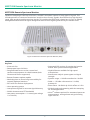
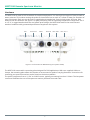
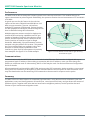
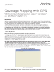
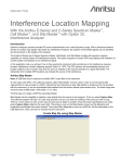
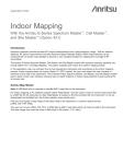
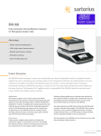
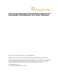
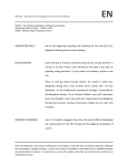
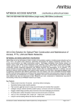
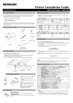
Product Brochure
MS27102A
Remote Spectrum Monitor
MS27102A Remote Spectrum Monitor
Introduction
With the rapid expansion of wireless communications, the need for robust networks relatively free of
interference continues to grow. Capacity will be degraded by the presence of illegal or unlicensed signals that
interfere with needed transmissions. These signals can be periodic or present at different frequencies over
time, making the discovery and removal of these sources of interference a significant challenge.
A spectrum monitoring system will facilitate the identification and removal of illegal or unlicensed interference
signals. By monitoring spectrum on a continual basis, problem signals can be identified as they occur in real
time. Patterns of unwanted signal activity can also be examined, providing an efficient way to characterize and
locate the source of the interference problem.
In addition to interference detection, spectrum monitoring is also used to characterize spectrum occupancy.
Government regulators and operators are often interested in determining the usage rate for various frequency
bands. Monitoring these frequencies provides the information needed to optimize spectrum for maximum
utilization. Spectrum can be re-purposed for other applications or multiplexed with other signals using
cognitive radio techniques.
Spectrum monitoring can also serve to enforce compliance with government regulations. Police, fire fighters,
air traffic control, military and emergency services must all have access to communications free of impediments
and distortion. Compliance with spectrum regulations is often enforced by spectrum monitoring. Figure 1
shows the MS27102A deployed to monitor Positive Train Control (PTC) frequencies. PTC is being deployed
worldwide to provide automated signaling for train control. The MS27103A can also be used inside the train to
insure wireless integrity.
Computer-aided
Dispatching &
Back Office Server
Systems
Communication
Network Component
Base
Station
Database
Location Reports
Signal
Status
Anritsu
Rack Mount
Spectrum
Monitor
MS27102A
Wayside Signal
Station
Onboard
System
Figure 1: Spectrum Monitoring System monitoring PTC frequencies
2
MS27102A Remote Spectrum Monitor
MS27102A Remote Spectrum Monitor
Capable of sweeping at rates up to 24 GHz/s, the MS27102A allows capture of many types of signals. This
includes periodic or transient transmissions as well as short “bursty” signals. Also featured is a high dynamic
range, high sensitivity and low spurious signals. This enables the MS27102A ( shown here in Fig 2) to reliably
distinguish between low-level signals being observed and those signals generated by the monitor itself.
Figure 2: MS27102A Outdoor Spectrum Monitor (IP67)
Key facts
• 9 kHz to 6 GHz
• Integrated GPS receiver for monitoring location
and for time synchronization applications
• Sweep speed up to 24 GHz/s
• Gigabit Ethernet available for high speed
transmissions
• Integrated web server to view, control and
conduct measurements via a web browser (both
Chrome and FireFox supported)
• Interference analysis: spectrogram and signal
strength
• Remote firmware update capable
• Dynamic range: > 106 dB normalized to 1 Hz BW
• Watchdog timer to insure long-term stability for
remotely deployed monitors
• DANL: <–150 dBm referenced to 1 Hz BW,
preamp On
• IP67 rated for outdoor deployments
• Phase noise: –99 dBc/Hz @ 10 kHz offset at 1 GHz
• Linux operating system
• IQ block mode and streaming with time stamping
for TDOA applications
• Low spurious signals for accurate signal discovery
• 20 MHz instantaneous FFT bandwidth
• VisionTM software optional for automated spectrum
measurements, setting alarms and geo-locating
signal sources
• Low power consumption < 11 watts (input voltage
11 to 24 VDC)
3
MS27102A Remote Spectrum Monitor
Designed For Remote Applications
With monitors potentially being deployed hundreds or thousands of kilometers from the control center, it is
imperative that each probe remain operational under all types of conditions. The MS27102A is designed for
robust field deployments, with capabilities for remote power cycling, automated system recovery protocols and
firmware updates “pushed” to the monitor remotely.
In the event of an application error or power fluctuation which causes an ongoing interruption in monitor
communication, a re-boot policy is implemented to bring the remote probe back to its previous state. Under
these conditions, the current firmware is automatically reloaded and on-line operation is restored. Instrument
settings are also restored to their previous state.
A “Golden” firmware image is also placed on each unit in a secure location in memory. If for any reason the
firmware in the unit becomes corrupted, a Golden Image is used to bring back full operation of the probe. This
feature is particularly useful for remote firmware updates.
Figure 3: MS27102A Outdoor Spectrum Monitoring System
Remote Firmware Updates
There are several stages or “checks” performed when a new
firmware package is downloaded remotely into the instrument. Once
a new firmware image is downloaded to the monitor, various tests
are performed to insure the code was properly transmitted without
error (see Fig 4). The code is then transferred into probe memory
and installed. If a failure occurs during firmware acquisition or
validation, the process is aborted and the failure status is returned
to the user. If the firmware update is installed but does not operate
correctly, the Golden Image automatically replaces the downloaded
firmware to keep the remote monitor operational.
The Golden Image feature provides the user with assurance that the
monitor stays in operation when changes are made to the code. Any
bug fixes, updates or user requested features can then be remotely
sent to the spectrum monitor and safely incorporated.
Validate
Firmware
Validation
Error?
Do Not
Update
Boot Normal
Image
Application
Error?
Boot Golden
Image
Figure 4: Firmware Update Policy
4
MS27102A Remote Spectrum Monitor
Integrated Web Server
The MS27102A features an integrated web server.
Using an internet browser (Chrome and FireFox are
supported), a user from anywhere in the world can log
in to the spectrum monitor and control any of its
features. This includes such parameters as frequency
settings, RBW/VBW control, reference level
configuration and many other settings relevant to the
user’s spectrum monitoring application. Trace data,
spectrograms and other measurements can be viewed
inside the browser window. A key advantage in using
the web server is that it is platform agnostic. Any
electronic device capable of rendering a browser will
work with the web server. Users can utilize their PC/
laptop, tablet or even a smartphone to view the
spectrum and change instrument settings. The
MS27102A features Gbit Ethernet, allowing fast
transfers of measurement data and control
information. Figure 5 shows the server application
displayed on a smartphone.
Figure 5: User interface displayed on smartphone
See figure 6 below for the main user interface provided by the web server.
Figure 6. Screenshot of user interface
5
MS27102A Remote Spectrum Monitor
Hardware
The MS27102A is rated to IP67 standards for outdoor deployment. It is dust tight (no ingress of dust) as well as
water resistant. This involves testing the probe for immersion into as much as 1 meter of water for durations of
up to 30 minutes. Each port on the unit is ruggedized and weatherized. Ports include power, RF Input, Gbit
Ethernet and GPS antenna. See figure 7 for port positioning. With an operating temperature range from –40 ⁰C
to +55 ⁰C, a rugged weatherized case and splash proof design, the MS27102A works in the most extreme
weather conditions with guaranteed performance anywhere and anytime.
GPS
No Connect
Power
Ethernet
RF In Port 2
RF In Port 1
Figure 7. Port locations on MS27102A (2-port option shown)
The MS27102A comes with a mounting plate designed for field applications. With user supplied U-Bolts or
clamps, the mounting plate allows the monitor to be mounted on poles of varying diameters. Instructions for
mounting your spectrum monitor can be found on the Anritsu website.
The probe uses power from a 11 VDC to 24 VDC source, typically consuming less than 11 Watts. The low power
consumed facilitates the use of the spectrum monitor powered from solar cells.
6
MS27102A Remote Spectrum Monitor
Key Applications
• Radio surveillance and monitoring
• Detection of illegal or unlicensed transmitters,
including AM/FM and cellular broadcasts
• Coverage measurements
• Spectrum occupancy and frequency band clearing
• Fast and efficient detection and elimination of
interference sources
• Monitor jails/prisons for illegal broadcasts
• Security at military facilities, national borders,
utilities, airports and other sensitive sites
(see fig. 8)
• Spectrum monitoring associated with lab RF
testing
• Government regulators enforcing spectrum
policies
Fig 8: Anritsu remote spectrum monitor positioned at airport
Signals of Interest
The wide variety of signals to be monitored fall into several categories. Each of these types of signals will be
examined in some detail. These include:
• Intentional interference (including illegal or unlicensed broadcasts)
• Accidental interference
• Occupancy
Intentional Interference
Illegal AM/FM and video broadcasts are found in many parts of the world. These signals can be generated by
pirated broadcast equipment or by using over-powered CB radios. Figure 9 shows a table listing interference
complaints per year registered by the UK
government communications regulator Ofcom. In
YEAR
INTERFERENCE COMPLIANTS
this table, ‘Critical service’ refers to interference
reports affecting life services communications.
Critical service
All other
Additionally, jammers are sometimes used for
applications such as preventing students from
cheating on tests, stopping employees from taking
phone calls on company time or to prevent inmates
from making illicit calls from prisons. Jammer signals
can often leak out into the wider environment,
interfering with other legitimate services. Mitigating
these types of interference has become a high
priority with government regulators.
London
Rest of UK
London
Rest of UK
1010
29
4
506
72
2011
35
0
424
69
2012
36
2
288
48
2013
21
5
179
93
Fig 9: Interference complaints published by Ofcom,
communications regulator in the UK
7
MS27102A Remote Spectrum Monitor
Accidental Interference
A wide variety of accidental interference can be seen in the spectrum. A common problem is cable TV leakage.
This type of leakage exists both from cable signals leaking into the outside environment as well as from external
signals leaking into the cable system. This problem has been enhanced with the transmission of cable signals
into frequency bands used by broadcasters and cellular operations (such as the 700 MHz LTE band).
DECT phones also cause interference problems, particularly when people bring their wireless phones along when
moving from one country to another. DECT frequencies vary in different countries, providing the potential for
interference when transported. Figure 10 below shows spectrum used in the U.S. for certain cellular frequencies.
DECT phones brought by travelers from other countries can often cause interference.
BRAZIL
DECT
JAPAN
DECT
EUROPE
DECT
A2
A3
D
B1
B2
B3
E
F
C1
C2
NA
DECT
C3
A1
A3
D
B1
B2
B3
E
F
C1
C2
C3
1930 MHz
1920 MHz
1910 MHz
North America PCS Uplink
1900 MHz
1890 MHz
1880 MHz
1850 MHz
North America PCS Uplink
A2
1990 MHz
A1
LATIN AMERICA
CHINA
DECT (Pre 2003)
Figure 10: DECT phones improperly used can cause unintentional interference
Other sources of interference include cellular signals (due to antenna tilt or azimuth errors), repeaters
oscillating, wireless microphone problems, power equipment and many others.
Occupancy
With the rapid demand for available spectrum from both public and private sectors, new ways are being
investigated to allow more efficient use of various frequency bands. A lot of the spectrum is potentially
underutilized, providing the
opportunity to re-purpose existing
spectrum with additional
Radio band 400-470 MHz
applications.
TV Band IV & V, 470-830 (862) MHz
Spectrum occupancy measurements
quantify the amount of usage of
frequency bands over a given period
of time (see figure 11). Remote
spectrum probes are used to
monitor a band of frequencies,
recording spectral histories as a
function of time.
GSM 900, 880 (888)-915 MHz, 925 (933)-960 MHz
Radio band 960-1710 MHz
GSM 1800, 1710-1785 MHz, 1805-1880 MHz
DECT, 1880-1900 MHz
UMTS, 1900-2025 MHz, 2110-2200 MHz
ISM, 2.4-2.5 GHz
Radio band 400 MHz-3 GHz
Radio band 400 MHz-6 GHz
City A
City B
City C
0
20
40
Spectrum Utilization [%]
Figure 11: Spectrum occupancy measurement
8
MS27102A Remote Spectrum Monitor
Performance
The MS27102A is able to sweep the frequency spectrum at rates up to 24 GHz/s. This enables the user to
capture intermittent or pulsed signals. Additionally, the spectrum monitor has an instantaneous FFT bandwidth
of 20 MHz.
A typical use case for this feature is the real-time
capture of the entire FM radio band (88 MHz to 108
MHz in most countries). The user can perform
multiple FFT captures of FM signals, storing the data
for later playback and analysis. Unlicensed signals can
then be identified using this information.
MS27102A
MS27102A
Multiple spectrum sensors can also be deployed to
extend the RF monitoring capabilities and for geolocation of signals of interest. Using three or more
probes, Anritsu’s optional Vision™ software can be
used to position an interferer signal or illegal
broadcast. Additionally, IQ measurements are time
stamped using the probe’s GPS receiver. This enables
the user to employ their own software using Time
Distance of Arrival (TDOA) capabilities to find
interferers, given each IQ measurement is precisely
time stamped. See figure 12 for TDOA example.
MS27102A
MS27102A
MS27102A
Geo-locating illegal broadcast station
MS27102A
Figure 12: Time Distance of Arrival for geo-locating
interference signal
Communications
Communications with the MS27102A are conducted via wired Ethernet. Each monitor is shipped with a preprogrammed static IP address. After making a connection with this IP address, users can then change the
address to a different static IP. Alternatively, DHCP or DNS may be used. See Anritsu’s Ethernet Configuration
Guide for details.
All commands and inquiries with the MS27102A are done using SCPI commands. Anritsu provides a user manual
listing each SCPI command, a description of each command and the correct syntax for each command. Users
may also download a text file containing SCPI commands to be executed in sequence on the probe.
Summary
The MS27102A is the ideal solution for unwanted signal detection. Using Anritsu’s Vision software or your own
applications, users can identify patterns of interference, record spectrum history and geo-locate the sources of
problem signals. Together with other Anritsu interference mitigation products, Anritsu provides the total
solution to your interference mitigation needs.
9
• United States
Anritsu Company
1155 East Collins Boulevard, Suite 100,
Richardson, TX, 75081 U.S.A.
Toll Free: 1-800-267-4878
Phone: +1-972-644-1777
Fax: +1-972-671-1877
• Canada
Anritsu Electronics Ltd.
700 Silver Seven Road, Suite 120,
Kanata, Ontario K2V 1C3, Canada
Phone: +1-613-591-2003
Fax: +1-613-591-1006
• Brazil
Anritsu Electrônica Ltda.
Praça Amadeu Amaral, 27 - 1 Andar
01327-010 - Bela Vista - São Paulo - SP - Brazil
Phone: +55-11-3283-2511
Fax: +55-11-3288-6940
• Mexico
Anritsu Company, S.A. de C.V.
Av. Ejército Nacional No. 579 Piso 9, Col. Granada
11520 México, D.F., México
Phone: +52-55-1101-2370
Fax: +52-55-5254-3147
• United Kingdom
Anritsu EMEA Ltd.
200 Capability Green, Luton, Bedfordshire LU1 3LU, U.K.
Phone: +44-1582-433280
Fax: +44-1582-731303
• France
Anritsu S.A.
12 avenue du Québec, Batiment Iris 1-Silic 612,
91140 Villebon-sur-Yvette, France
Phone: +33-1-60-92-15-50
Fax: +33-1-64-46-10-65
• Germany
Anritsu GmbH
Nemetschek Haus, Konrad-Zuse-Platz 1
81829 München, Germany
Phone: +49-89-442308-0
Fax: +49-89-442308-55
• Italy
Anritsu S.r.l.
• Sweden
Anritsu AB
Kistagången 20B, 164 40 KISTA, Sweden
Phone: +46-8-534-707-00
Fax: +46-8-534-707-30
• Finland
Anritsu AB
Teknobulevardi 3-5, FI-01530 Vantaa, Finland
Phone: +358-20-741-8100
Fax: +358-20-741-8111
• Denmark
Anritsu A/S
Kay Fiskers Plads 9, 2300 Copenhagen S, Denmark
Phone: +45-7211-2200
Fax: +45-7211-2210
• Russia
Anritsu EMEA Ltd.
Representation Office in Russia
Tverskaya str. 16/2, bld. 1, 7th floor
Moscow, 125009, Russia
Phone: +7-495-363-1694
Fax: +7-495-935-8962
• Spain
Anritsu EMEA Ltd.
Representation Office in Spain
Edificio Cuzco IV, Po. de la Castellana, 141, Pta. 8
28046, Madrid, Spain
Phone: +34-915-726-761
Fax: +34-915-726-621
• United Arab Emirates
Anritsu EMEA Ltd.
Dubai Liaison Office
P O Box 500413 - Dubai Internet City
Al Thuraya Building, Tower 1, Suite 701, 7th floor
Dubai, United Arab Emirates
Phone: +971-4-3670352
Fax: +971-4-3688460
• India
Anritsu India Pvt Ltd.
2nd & 3rd Floor, #837/1, Binnamangla 1st Stage,
Indiranagar, 100ft Road, Bangalore - 560038, India
Phone: +91-80-4058-1300
Fax: +91-80-4058-1301
• Singapore
Anritsu Pte. Ltd.
11 Chang Charn Road, #04-01, Shriro House
Singapore 159640
Phone: +65-6282-2400
Fax: +65-6282-2533
• P. R. China (Shanghai)
Anritsu (China) Co., Ltd.
2701-2705, Tower A,
New Caohejing International Business Center
No. 391 Gui Ping Road Shanghai, Xu Hui Di District,
Shanghai 200233, P.R. China
Phone: +86-21-6237-0898
Fax: +86-21-6237-0899
• P. R. China (Hong Kong)
Anritsu Company Ltd.
Unit 1006-7, 10/F., Greenfield Tower, Concordia Plaza,
No. 1 Science Museum Road, Tsim Sha Tsui East,
Kowloon, Hong Kong, P. R. China
Phone: +852-2301-4980
Fax: +852-2301-3545
• Japan
Anritsu Corporation
8-5, Tamura-cho, Atsugi-shi,
Kanagawa, 243-0016 Japan
Phone: +81-46-296-6509
Fax: +81-46-225-8359
• Korea
Anritsu Corporation, Ltd.
5FL, 235 Pangyoyeok-ro, Bundang-gu, Seongnam-si,
Gyeonggi-do, 463-400 Korea
Phone: +82-31-696-7750
Fax: +82-31-696-7751
• Australia
Anritsu Pty Ltd.
Unit 21/270 Ferntree Gully Road,
Notting Hill, Victoria 3168, Australia
Phone: +61-3-9558-8177
Fax: +61-3-9558-8255
• Taiwan
Anritsu Company Inc.
7F, No. 316, Sec. 1, Neihu Rd., Taipei 114, Taiwan
Phone: +886-2-8751-1816
Fax: +886-2-8751-1817
Via Elio Vittorini 129, 00144 Roma Italy
Phone: +39-06-509-9711
Fax: +39-06-502-2425
Please Contact:
The Master Users Group is an organization dedicated to
providing training, technical support, networking opportunities
and links to Master product development teams. As a member
you will receive the Insite Quarterly Newsletter with user stories,
measurement tips, new product news and more.
Visit us to register today: www.anritsu.com/MUG
Training at Anritsu
Anritsu has designed courses to help you stay up to date with
technologies important to your job.
For available training courses visit: www.anritsu.com/training
Anritsu utilizes recycled paper and environmentally conscious inks and toner.
® Anritsu All trademarks are registered trademarks of their
respective owners. Data subject to change without notice. For
the most recent specifications visit: www.anritsu.com
11410-00875, Rev. B Printed in United States 2015-09
©2015 Anritsu Company. All Rights Reserved.