1
2
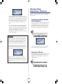
Contents
PRECAUTIONS ............................................................4
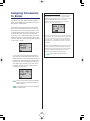
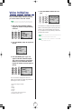
Playing Arpeggiated Chords ...........................................35
INTRODUCTION
Using The Step Sequencer ..........................................37
How To Use This Manual ..............................................5
Step Sequencer On/Off .................................................38
Main Features...............................................................5
Step Sequencer Hold Modes ...........................................38
The AN1x At A Glance .................................................6
Voice Pattern And User Pattern Banks...............................39
The Making Of A Modern Classic .................................8
Playing Step Sequencer Patterns ......................................40
What Is A Voice? ..........................................................9
Step Sequencer Edit .......................................................44
Arpeggio MIDI Output....................................................37
AN1x Memory Structure ..............................................9
Step Sequencer MIDI Output ...........................................46
Using The Free EG ......................................................47
Free EG Parameters .......................................................47
ANALOG PHYSICAL
MODELING SYNTHESIS
Using The Control Features.........................................49
Real-time Control............................................................49
AN1x Tone Generator ................................................10
Utility Control Assign Function .........................................50
Control Matrix ...............................................................51
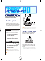
GETTING STARTED
System Examples .......................................................12
FEATURE REFERENCE
Switching On The Power ................................................13
Voice Select.................................................................52
Playing The Demo Songs............................................13
Knob Edit ....................................................................53
Basic Operation ..........................................................14
Knob Parameters .......................................................54
AN1x Operating Modes.................................................14
PEG/LFO ......................................................................54
Selecting Voices.............................................................14
SYNC/FM ....................................................................58
Using The Controllers .....................................................15
VCO1 ..........................................................................61
CONTROL Knobs And Parameter Groups .........................16
VCO2 ..........................................................................63
AN1x Quick Tour........................................................17
VCF..............................................................................64
Exploring The Factory-set Voices ......................................17
MIX/VCF ......................................................................66
Selecting Scenes And Scene Morphing .......................19
VCA .............................................................................68
Scene Memories ............................................................19
ASSIGN .......................................................................70
Scene Control................................................................20
Panel Parameter Edit..................................................71
Scene Store Function ......................................................21
Edit Procedure ...............................................................71
Scene Load Function ......................................................22
Edit Parameters ..........................................................72
Scene Swap Function .....................................................22
VOICE SCENE SETUP ....................................................72
Selecting Layer Modes................................................22
VOICE COMMON ........................................................77
Layer Modes .................................................................22
VOICE FREE EG ............................................................81
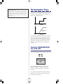
Portamento Play.........................................................24
VOICE ARPEGGIO/SEQ ................................................85
Turning PORTAMENTO On And Off.................................24
SEQ EDIT/SETUP ...........................................................89
Setting Portamento Time..................................................25
UTILITY SETUP................................................................92
Selecting Portamento Modes ...........................................25
Voice Recall ................................................................96
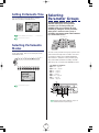
Selecting Parameter Groups.......................................25
Voice Initialize ............................................................97
Using The CONTROL Knobs ........................................26
Store ...........................................................................98
Assigning Parameters To Knobs .......................................27
Voice Store....................................................................98
Using The Panel Edit Matrix .......................................28
Scene Store...................................................................99
Editing Voices .............................................................29
Factory Settings ........................................................100
Voice Edit Procedure ......................................................29
Creating Original Voices ................................................30
Store Operations ........................................................33
APPENDIX
Turning ARPEGGIO/SEQ On And off ..........................33
Voice Creation Examples ..........................................101
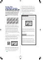
Using The Arpeggiator ...............................................33
About MIDI ...............................................................109
Arpeggiator On/Off ......................................................33
Error Messages .........................................................112
Arpeggio Hold Function..................................................34
Troubleshooting ........................................................113
Arpeggio Pattern Types...................................................34
Blank Chart ..............................................................114
Arpeggio Subdivide .......................................................34
Specifications ............................................................116
Index ........................................................................117
3
PRECAUTIONS
PLEASE READ CAREFULLY BEFORE PROCEEDING
* Please keep these precautions in a safe place for future reference.
WARNING
Always follow the basic precautions listed below to avoid the possibility of serious injury or even death from electrical
shock, short-circuiting, damages, fire or other hazards. These precautions include, but are not limited to, the following:
• Do not open the instrument or attempt to disassemble the internal parts
or modify them in any way. The instrument contains no userserviceable parts. If it should appear to be malfunctioning, discontinue
use immediately and have it inspected by qualified Yamaha service
personnel.
• Use the specified adaptor (PA-3B or equivalent, recommended by
Yamaha) only. Using the wrong adaptor can result in damage to the
instrument or overheating.
• Before cleaning the instrument, always remove the electric plug from
the outlet. Never insert or remove an electric plug with wet hands.
• Do not expose the instrument to rain, use it near water or in damp or
wet conditions, or place containers on it containing liquids which
might spill into any openings.
• Check the electric plug periodically and remove any dirt or dust which
may have accumulated on it.
• If the AC adaptor cord or plug becomes frayed or damaged, or if there
is a sudden loss of sound during use of the instrument, or if any
unusual smells or smoke should appear to be caused by it,
immediately turn off the power switch, disconnect the adaptor plug
from the outlet, and have the instrument inspected by qualified Yamaha
service personnel.
CAUTION
Always follow the basic precautions listed below to avoid the possibility of physical injury to you or others, or damage
to the instrument or other property. These precautions include, but are not limited to, the following:
• Do not place the AC adaptor cord near heat sources such as heaters or
radiators, and do not excessively bend or otherwise damage the cord,
place heavy objects on it, or place it in a position where anyone could
walk on, trip over, or roll anything over it.
• Do not operate the instrument for a long period of time at a high or
uncomfortable volume level, since this can cause permanent hearing
loss. If you experience any hearing loss or ringing in the ears, consult
a physician.
• When removing the electric plug from an outlet, always hold the plug
itself and not the cord.
■ REPLACING THE BACKUP BATTERY
• This instrument contains a non rechargeable internal backup battery
which permits internal data to remain stored even when the power is
off. When the backup battery needs replacing, the message "Battery
Low" will display in the LCD. When this happens, immediately back up
your data (using an external device such as the floppy disk-based
Yamaha MIDI Data Filer MDF2), then have qualified Yamaha service
personnel replace the backup battery.
• Do not attempt to replace the backup battery yourself, in order to
prevent the possible serious hazards. Always have qualified Yamaha
service personnel replace the backup battery.
• Never place the backup battery in a location that a child can reach,
since a child might accidentally swallow the battery. If this should
happen, consult a physician immediately.
• Do not connect the instrument to an electrical outlet using a multipleconnector. Doing so can result in lower sound quality, or possibly
cause overheating in the outlet.
• Remove the adaptor plug from the outlet when the instrument is not to
be used for extended periods of time, or during electrical storms.
• Before connecting the instrument to other electronic components, turn
off the power for all components. Before turning the power on or off for
all components, set all volume levels to minimum.
• Do not expose the instrument to excessive dust or vibrations, or
extreme cold or heat (such as in direct sunlight, near a heater, or in a
car during the day) to prevent the possibility of panel disfiguration or
damage to the internal components.
■ SAVING USER DATA
• Do not use the instrument near other electrical products such as
televisions, radios, or speakers, since this might cause interference
which can affect proper operation of the other products.
• Save all data to an external device such as the Yamaha MIDI Data Filer
MDF2, in order to help prevent the loss of important data due to a
malfunction or user operating error.
• Do not place the instrument in an unstable position where it might
accidentally fall over.
Yamaha cannot be held responsible for damage caused by improper use or
modifications to the instrument, or data that is lost or destroyed.
• Before moving the instrument, remove all connected adaptor and other
cables.
• When cleaning the instrument, use a soft, dry cloth. Do not use paint
thinners, solvents, cleaning fluids, or chemical-impregnated wiping
cloths. Also, do not place vinyl or plastic objects on the instrument,
since this might discolor the panel or keyboard.
Always turn the power off when the instrument is not in use.
The LCD screens and diagrams in this owner's manual are for
instructional purposes only, and may be different from the ones on your
instrument.
• Do not rest your weight on, or place heavy objects on the instrument,
and do not use excessive force on the buttons, switches or connectors.
4
Congratulations! And thank you for choosing Yamaha. You are now the proud owner of the AN1x Control Synthesizer, a
fully-professional digital keyboard with powerful sound and versatile real-time control features. The AN1x is a modern
music dynamo capable of faithfully delivering the warm, fat, punchy sounds of the legendary analog synths—with the
same familiar oscillator, filter and other sound creation elements and intuitive, "hands on" style of operation—plus all the
sophisticated flexibility you'd expect from a professional digital synthesizer.
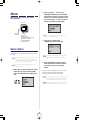
How To Use This Manual
GETTING STARTED Provides a basic overview of how to set up
your AN1x and quickly familiarize yourself with all its key features
and operations. We recommend you actually be sitting in front of
your AN1x as you read through the GETTING STARTED section,
so you can try out each feature along the way to get a thorough
understanding of how the AN1x works.
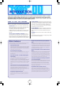
This owner’s manual provides your basic keys to unlocking the power of
the AN1x Control Synthesizer. It is divided into the following sections:
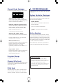
INTRODUCTION Provides a brief rundown of the AN1x’s main
features and description of all front and rear panel controls along
with information about the AN1x’s memory structure. We
recommend you take a few minutes and read the
INTRODUCTION section carefully before you get started in order
to familiarize yourself with the basic features and capabilities of
the AN1x.
FEATURE REFERENCE Provides a comprehensive explanation of
all AN1x features. This is in essence a dictionary which you can
refer to any time you need to know the details about any given
feature.
APPENDIX Provides information related to MIDI, troubleshooting,
and more.
ANALOG PHYSICAL MODELING SYNTHESIS Provides an
overview of the basic concept of the tone generation technology,
plus descriptions of basic terminology and a signal flow block
diagram, in order to give you an understanding of what’s going on
inside the instrument as you twiddle the knobs and set parameters.
A separate Data List book provides voice, Arpeggiator Type, Effect
Type and other lists and information.
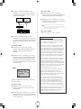
Arpeggiator with 30 patterns and various play options, plus MIDI data
output
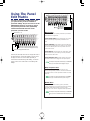
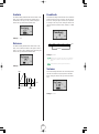
The Arpeggiator lets you play perfect arpeggiated chords at the simple press of a key. You can
have the Arpeggiator play only one or both Scenes, or play one Scene to the left of the Split
Point while you play the other Scene normally to the right. You can choose from various types
of arpeggio patterns, including Up, Down, and Up&Down across one or more octaves, plus
various special patterns including Techno, House, Random, and more. The arpeggio pattern
data can be output via MIDI on its own MIDI channel.
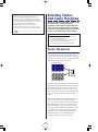
Main Features
The AN1x Control Synthesizer is a truly innovative professional keyboard with enormously flexible
sound and performance capabilities. Following is a brief rundown of the main features:
Analog Physical Modeling synthesis
The AN1x generates amazingly high quality synth sounds in much the same way as traditional
legendary analog synthesizers—using voltage controlled oscillators and filters, low frequency
oscillators, ring modulator and voltage controlled amplifiers—but with the additional benefits
of digital multi-effects, MIDI control and much more.
Easy-play/edit “Step Sequencer” with 128 Voice Patterns and 128 User
Patterns
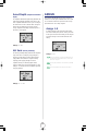
The Step Sequencer permits quick, easy creation of highly sophisticated looped patterns which
can be triggered from the keyboard in a variety of ways. Each individual step event (Note,
Velocity, Gate Time, and Control Change) can be accessed and edited by a specific CONTROL
knob, over a maximum of 16 steps. There are a variety of handy Step Sequencer edit and
play options, including “Play Effects” which give you detailed control over the “feel” of your
sequence. Pattern event data can be output via MIDI on its own MIDI channel.
128 voices and maximum 10 notes polyphony
The AN1x comes with an impressive array of 128 voices preprogrammed and ready to play, each of which
can be edited and overwritten to store your own. Ten notes of polyphony provide for versatile SINGLE,
DUAL and SPLIT play options.
Intuitive interface with "hands on" voice editing and multiple assignable
real-time controllers
The AN1x's eight CONTROL knobs and panel Edit matrix give you direct and instant access to
many parameters as you play. All controllers are assignable, including [PITCH] and
[MODULATION] wheels and various foot pedals, plus the [RIBBON] controller with horizontal slide
(X) and pressure (Z) control of filter, LFO, delay and more. The Control Matrix function permits
easy assignment of up to 16 sets of "source" controllers (MW, FC, Key Touch, etc.) to destination
parameters (VCA, Filter, LFO, etc.) for each Scene, all of which can be stored as voice data for
each voice.
4-track “Free EG” records and plays real-time changes of knob positions
for up to four different parameters
The 4-track Free EG lets you record real-time CONTROL knob movements, in order to “hand
draw” filter, resonance, LFO and many other available parameters over time—and have them
play back automatically by simply playing a voice. You can control up to four different
parameters independently, each recorded into its own Free EG track. Ideal for those times
when you wish you had an extra couple of pairs of hands, the Free EG lets you build up an
incredibly complex, completely unique voice.
2 Scene memories for each voice, with real-time morphing between Scenes
Each voice has two Scenes, each of which can be selected by pressing a [SCENE] switch. This
provides two distinct sounds within each voice available for instant recall as you play. You can
press both [SCENE] switches to activate the "Scene Control" function, and roll the
[MODULATION] wheel (or press a foot pedal or use any other continuous controller) to morph,
or cross-fade between the sounds of Scene 1 and Scene 2 as you play.
Programmable multi-effects and 3-band EQ for each voice
The AN1x has three types of programmable multi-effects plus EQ built into the voice
architecture, which lets you customize the effects configuration for each voice. There are 8
Reverb effects, 5 Delay effects, 14 Variation effects (which includes Chorus, Auto Pan, Pitch
Change, Compressor, Distortion effects and more), and a stereo 3-band Equalizer. An Effect
Bypass function lets you bypass all effects or specific ones at the press of a switch.
Six types of Layers to choose from for each voice
SINGLE, UNISON, DUAL, DUAL UNISON, SPLIT, and SPLIT UNISON Layer modes give you a
wide choice for control over how the two Scenes are configured to play in relation to each
other for each voice.
5
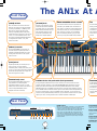
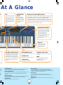
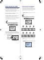
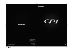
The AN1x At A
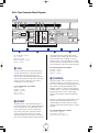
Front Panel
[SCENE] switches
Each of the AN1x's 128 voices has two Scene
memories, each of which are instantly accessible
by pressing the [SCENE 1] or [SCENE 2] switch.
Each Scene can have its own distinct sound.
Pressing both [SCENE] switches simultaneously
activates the Scene Control function, which lets you
"morph", or cross-fade between Scenes in realtime using the assignable [MODULATION] wheel,
an assignable Foot Controller, or any other
continuous controller.
[VOLUME] knob
KNOB PARAMETER GROUP switches
LCD
This knob controls the AN1x’s overall
volume level output from the PHONES
and OUTPUT jacks. Turn the [VOLUME]
between left-most (minimum) and rightmost (maximum) positions to set the
proper listening level whether using
headphones or amplified speakers.
These switches determine which set of parameters are
controlled by the CONTROL knobs. The switches are
color coded in cross-reference to the parameter names
as printed in the same color on the panel beside each
knob. Whenever you select a voice, the [ASSIGN]
switch is automatically selected, to give you instant
access to your assigned CONTROL knob parameters.
The back-lit LCD
Display) provide
of information w
indicates the cu
status of the AN
voices, turn kno
switches.
PHONES
DC IN
R
L / MONO
POWER
FOOT
FOOT
VOLUME CONTROLLER
FOOT
SWITCH
IN
OUT
THRU
MIDI
OUTPUT
Mode
Poly
Algorithm
PEG Decay
Sync Pitch
PEG Depth
Sync Pitch
Depth
PEG Sw
Sync Pitch
Src
Port Time
Temp
Wave
Wave
Pitch
Pitch
Fine
Fine
Edge
Attack
VCO1
Level
Decay
VCO2
Level
Sustain
Ring
Mod
Release
Attack
[RIBBON] controller
VOLUME
The assignable [RIBBON] controller gives you
horizontal slide (X) and pressure (Z) control of
designated controllable parameters as you play,
including filter cutoff, resonance, LFO, panpot,
reverb, and more.
FM Depth
PW
PWM Depth
VCF
Cutoff
HPF
Feedback
SCENE
ASSIGN 2
LFO1 Wave
PW
CTRL
Sustain
Decay
ASSIGN 1
Sync
Pmod Sw
ASSIGN 5
FM Src1
PWM Depth
PWM Src
Reso
nance
VCF
Type
Volume
ASSIGN 4
LFO1 Dly
PWM Src
Fmod
Depth
FEG
Depth
Amod Depth
ASSIGN 6
Noise
Level
Release
ASSIGN 3
LFO1 Spd
Edge
ASSIGN 7
FM Src2
PmodDepth
SYNC/FM
PEG/ LFO
VCO1
VCO2
LFO2 Spd
PmodDepth
VCF
MIX / VCF
Key
Track
VCA
ASSIGN
Vel
Sens
Track
Trigge
PROGRAM CHANGE
KNOB PARAMETER GROUP
VWX
YZ
OTHERS
7
8
9
MNO
PQR
STU
4
5
6
DEF
GHI
JKL
1
2
3
ABC
0
Vel Sens
Comm
Arp /S
Knob
Event
Syste
Mstr Tu
DEMO
PORTAMENTO
LAYER
STORE
ARPEGGIO / SEQ
–
NO
YES/ ENTER
ASSIGN 8
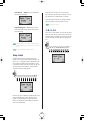
[PITCH] wheel
The [PITCH] wheel lets you bend the pitch up or
down as you play. It is spring-loaded to
automatically return to center position when you let
go of it. You can use the Control Matrix to designate
specific Pitch Bend parameters for the upper and
lower bend ranges for each Scene.
PITCH
[MODULATION] wheel
The assignable [MODULATION] wheel lets you
apply modulation or another designated
controllable parameter as you play, or morph
between Scenes when the Scene Control function is
active (and the [MODULATION] wheel is
designated as the source controller).
MODULATION
CONTROL knobs with push-switch (knob parameters)
PROGRAM
The eight assignable CONTROL knobs are used for real-time control and edit of the various tone
generator parameters, depending on which KNOB PARAMETER GROUP select switch is currently
selected, plus instant access to each step event when the [EDIT ROTARY] switch is set to the SEQ
EDIT/SETUP menu. Press a CONTROL knob (push-switch) to confirm the current parameter in the LCD.
Turn a CONTROL knob left to decrease values or right to increase them. Make fine edit adjustments by
turning a knob while pressing it. Since all CONTROL knobs are assignable, you can have each one
access one of many different available parameters to give you maximum real-time control over specific
aspects of your sound, including versatile control of external instruments via MIDI output.
The PROGRAM
used for selectin
currently selecte
Other functions
naming a User v
canceling ([NO]
operations.
Rear Panel
ASSIGNABLE
MIDI
THRU
OUT
IN
FOOT
SWITCH
FOOT
FOOT
CONTROLLER VOLUME
POWER
ON
OFF
OUTPUT
DC IN
R
6
L/MONO
PHONES
1 MIDI terminals
MIDI [IN], [OUT] and [THRU] terminals let you connect external MIDI
devices such as a MIDI keyboard, tone generator, sequencer or
computer or others, using a MIDI cable. [IN] is for input of MIDI data,
including data dumps from another AN1x or MIDI data storage
device. [OUT] is for output of MIDI data, including data dumps to
another AN1x or MIDI data storage device. [THRU] is for “daisychain” connection of additional MIDI instruments, as the MIDI data
received at the AN1x’s [IN] terminal is passed along unchanged to
the [THRU] terminal.
2 [FOOTSWITCH
An optional Yamaha
used to control hold
3 [FOOT CONTRO
An optional Yamaha
used for control of va
assignment.
4 [FOOT VOLUM
An optional Yamaha
to regulate overall vo
5 [POWER] switc
Press the [POWER] s
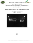
At A Glance
es
[EDIT ROTARY]
switch
LCD
The back-lit LCD (Liquid Crystal
Display) provides various types
of information which clearly
indicates the current operating
status of the AN1x as you select
voices, turn knobs and press
switches.
s
T
Parameter value [UP/DOWN] switches
These ten switches are used to access and edit specific parameters (as printed on the
panel), depending on which Edit menu is currently selected with the [EDIT ROTARY]
switch. Pressing the upper area of a parameter value [UP/DOWN] switch
increments the parameter value or setting, and pressing the lower area decrements
it. Simply pressing a switch once will display the parameter name and current value
or setting in the LCD. Thereafter, pressing or holding the upper or lower area of the
switch will change the value or setting accordingly.
The 6-position [EDIT
ROTARY] switch lets you
designate one of the six
Edit menus, as printed on
the panel to the right of
each menu.
THRU
DI
YZ
Vari EF/EQ
Param
Data
7
8
9
PQR
STU
4
5
6
DEF
GHI
JKL
1
2
3
Common
Arp /SEQ
DEMO
Unison
Detune
Name
Cursor
Char
Key Track
VOICE
COMMON
Track
Track No
Param
Scene Sw
Track Job
Rec
Copy
Undo
VOICE
FREE EG
MIDI
Ptn Tx Ch
Arpeggio
Subdivide
Play EF
Swing
Depth
Type/No
KbdMode
Hold
SceneSw
Knob
Event
1-8 / 9 -16
Step Hold
Pattern
Bank
No
System
Mstr Tune
Kbd Trans
Kbd Vel
MIDI
Tx Ch
Velocity
ANALOG PHYSICAL MODELING
LFO2
LFO1
VOICE
GateTime ARPEGGIO /SEQ
Base Unit
Length
LoopType
Ctrl No
SEQ
Store
SEQ
EDIT /SETUP
DeviceNo
Local
BulkDump
Ctrl
Device
Ctrl No
UTILITY
SETUP
VCO
VCO1
MIX/VCF
SYNC
MASTER
SLAVE
VCA
EFFECT
VOLUME
RING
MOD
VARI
EQ
FM
AEG
NOISE
DLY
REV
LAYER
–
NO
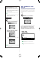
Synthesis Block Diagram
CONTROL SYNTHESIZER
CTRL
VCO2
PORTAMENTO
ABC
Length
Separate
EF
Bypass
Source
PEG
OTHERS
MNO
0
LFO Rst
Split Pnt
Track Common
LoopType
Trigger
PROGRAM CHANGE
VWX
Port
Tempo
VOICE
SCENE SETUP
Layer
Pan
Dly/Rev EF
Param
Data
Ctrl Matrix
Param
Set No
Mode
Poly
FEEDBACK
YES/ ENTER
STORE
ARPEGGIO/ SEQ
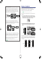
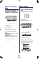
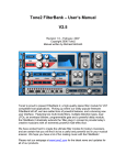
The Analog Physical Modeling synthesis
block diagram provides a handy visual
reference or reminder of how the signal
flows through the key blocks, or
components of the AN1x's tone
generation architecture, which is helpful
when manipulating the various
parameters during voice editing or realtime sound control.
Keyboard
The 61-key touch-sensitive
keyboard features Initial
(velocity) and After Touch
(pressure) control.
.
y
c
al MIDI
or
DI data,
ge
s to
sydata
ed to
PROGRAM CHANGE keypad
[PORTAMENTO] switch
[ARPEGGIO/SEQ] switch
The PROGRAM CHANGE keypad is primarily
used for selecting a voice or confirming the
currently selected voice name and number.
Other functions include selecting letters when
naming a User voice, and confirming ([YES]) or
canceling ([NO]) specific store and other
operations.
For turning the portamento function on and off.
For turning the Arpeggiator or Step Sequencer
on and off.
[LAYER] switch
For selecting one of the six Layer modes.
DEMO
[STORE] switch
Pressing [PORTAMENTO] and [LAYER]
simultaneously lets you access the
Demonstration songs.
For initiating Store operations.
2 [FOOTSWITCH] jack
An optional Yamaha FC4 or FC5 Footswitch connected to the [FOOTSWITCH] jack can be
used to control hold on/off, Portamento on/off and other discrete controllers.
6 [DC IN] terminal
Connect the supplied Yamaha PA-3B Power Adaptor to the [DC IN] terminal.
(CAUTION: Do not attempt to use an AC adaptor other than the Yamaha PA-3B or
equivalent, since the use of an incompatible adaptor may cause irreparable damage to
the AN1x, and may even pose a serious shock hazard.)
3 [FOOT CONTROLLER] jack
An optional Yamaha FC7 foot controller connected to the [FOOT CONTROLLER] jack can be
used for control of various continuous or discrete controllers, depending on controller
assignment.
7 OUTPUT jacks
The stereo OUTPUT jacks let you connect the AN1x to an external stereo
amplifier/speaker system. When using a mono system, connect it to the [L/MONO]
jack.
4 [FOOT VOLUME] jack
An optional Yamaha FC7 foot controller connected to the [FOOT VOLUME] jack can be used
to regulate overall volume (or any other assigned continuous controller function.).
5 [POWER] switch
Press the [POWER] switch to turn the AN1x on and off.
8 [PHONES] jack
The [PHONES] jack lets you connect a set of stereo headphones to the AN1x for private
listening.
7
The Making Of A Modern Classic
The classic analog synth sound is back with a vengeance and more popular than ever. Vintage analog synthesizers are hot
items, recirculating and finding their way into the arsenals of the world’s most innovative music makers, many of whom
weren’t even born when the voltage controlled synthesizer was coming of age more than a quarter of a century ago.
Enter the Yamaha AN1x Control Synthesizer—a modern classic in its own right—complete with the VCO, VCF, and VCA
blocks, or "modules" that give retro synths that famously fat, rich, warm sound, plus multiple knobs for controlling every nuance
of the sound, and even an on-board Arpeggiator and Step Sequencer for generating pattern loops at the press of a key.
What’s much more, however, is that the AN1x incorporates features that vintage synths could only dream about—like three onboard programmable digital multi-effects units and a 3-band stereo EQ, a multiple controller-to-parameter assignment architecture,
a 4-track Free EG for “hand drawing” real-time knob position movements of up to four different tone generator parameters, plus
real-time morphing between two different sounds, and more—all of which can be customized for each of the 128 voices and
stored as individual voice data.
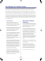
The History…
Enter Analog Physical
Modeling…
Why is the “analog sound” so popular in a digital
age? What long and winding road had to be
traveled—just to end up right back where we started
from? Let’s take a quick look at how we got from there
to here, and where here really is, anyway.
The classic analog synth never fell out of favor with the
world's most innovative musicians. That's because it
has a special punch, power, plus important elements of
interactivity that digital synths and samplers have
tended to lack by comparison.
Electronic music synthesis has been around in one form
or another since the beginning of the 20th Century. But
it wasn’t until the early 1970s that developments in
voltage controlled synthesis technology made the
concept practical—and affordable.
And now, with the demand for that "classic analog
sound" due to the global popularity of techno, trance,
and other modern forms of dance music, it's hardly
surprising that Yamaha—a company consistently at the
very pinnacle of electronic musical instrument
technology—would react to that demand and create a
completely new performance-oriented "control
synthesizer" that takes the company's original
breakthroughs in physical modeling synthesis and uses
it to digitally "model" the analog sound-generating
components which gives voltage controlled synthesis its
unique character and virtually unlimited range of
sound.
As such, the voltage controlled synthesizer became less
and less an experimental curiosity in the world’s great
universities and sound labs and more and more a
valid—and revolutionary—musical instrument in its own
right. It quickly became a staple in professional
recording studios, and its myriad sounds started
gracing the ears of millions through popular recordings
in literally all genres of music.
Then came the 1980s, and the introduction of wildly
popular, affordable-for-the-masses, great-sounding and
easy-to-use digital synths like the famous Yamaha DX7.
What followed was the MIDI revolution, which drove
the rapid development of ever-more-sophisticated multitimbral digital synthesizers and tone generators, along
with the overwhelming acceptance of digital sampling
which has literally changed the way we create and
listen to music. And all of which have gone hand-inhand with the desktop music revolution.
And package it with a host of digital extras to bring
the technology full circle with a completeness and utility
never before possible.
Most recently there has been the introduction of
breakthrough physical modeling synthesis technology,
which has been successfully applied to the accurate
reproduction of acoustic instrument sounds through
purely electronic means, as well as the creation of new
“hybrid-type” acoustic-oriented sounds.
All the tools are in the box. The rest is up to you….
In short, the AN1x is a logical—and timely—
development in the evolution of electronic musical
instrument history, based on the modern needs and
demands of the world’s cutting-edge musicians. And
once again, as is often the case with creations from
Yamaha, music history will never be the same.
8
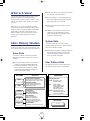
What Is A Voice?
● LAYER mode setting and Layer parameters including
Pan, Separation and Detune settings.
Over the years, the meaning of the term “voice”, when
applied to synthesizers, has varied depending on
manufacturers and models. In general, it means a sound,
which in some synths is called a “patch”, and in others a
“program”.
● VOICE COMMON (i.e., parameters which affect
both Scenes) settings including Tempo, Split Point,
Effect configurations and voice Name.
● Free EG parameter settings and track data and
other settings.
With the AN1x, a voice is a configuration of all tone
generator and other parameter settings, including effects
setups and data for a single Voice Pattern, but excluding
system settings or the bank of Step Sequencer User
Patterns. Therefore, each of the 128 voices in memory
can have its own unique configuration of all main
parameters.
● ARPEGGIO/SEQ switch status and the various
Arpeggiator and Step Sequencer parameter
settings, including Play Effect settings, plus Step
Sequencer Voice Pattern data.
System Data
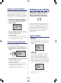
AN1x Memory Structure
System data is made up of the various “global”
parameter settings which remain in effect regardless of
which voice is selected, as follows:
The AN1x has a simple and straightforward memory structure. There
are only two main types of data: voice data and system data. There
is also a separate memory for the Step Sequencer User Pattern bank.
● UTILITY SETUP parameters, including the settings for
System tuning and keyboard transposition and
velocity, MIDI-related parameters, and Control
device and number assignments.
Voice Data
Voice data is comprised of the various parameter
settings which make up each of the 128 User voices,
as follows:
User Pattern Data
● Tone generator settings based on CONTROL knob
positions for each KNOB PARAMETER GROUP
parameter, PORTAMENTO switch status, Scene
status and Scene-related parameters, including
Control Matrix assignments, Mode settings and
Variation Effect Dry:Wet setting.
Voice Data
User Pattern data is made up of the Step Sequencer
User Pattern bank which holds 128 User Patterns.
System Data
128 User Voices
Tone Generator Knob Parameters
SCENE 1
PEG, LFO1, LFO2, VCO1, VCO2, SYNC, FM, MIXER
(NOISE, RING MODULATOR), VCF (FEG), VCA (AEG)
Utility Setup Parameters
SYSTEM:
MASTER TUNE, VELOCITY,
KEYBOARD TRANSPOSE
MIDI:
TRANSMIT CHANNEL,
RECEIVE CHANNEL (each Scene),
PATTERN TRANSMIT CHANNEL,
DEVICE NUMBER, LOCAL,
BULK DUMP, EFFECT BYPASS
Scene Setup Parameters
SCENE 2
LAYER
(SINGLE/UNISON/
DUAL/DUAL UNISON/
SPLIT/SPLIT UNISON)
POLY/MONO/LEGATO, PORTAMENTO MODE,
LFO RESET, CONTROL MATRIX (Assignments),
VARIATION EFFECT DRY:WET
Layer Parameters
CONTROL: ASSIGNABLE KNOB CONTROL
CHANGE NUMBERS, CONTROLLER
CONTROL CHANGE NUMBERS
PAN, SEPARATE, DETUNE
Voice Common Parameters
TEMPO, SPLIT POINT, EFFECT, NAME
Pattern Parameters
PORTAMENTO
(On/Off)
ARPEGGIO/SEQ
(On/Off)
ARPEGGIATOR or SEQUENCER,
ARPEGGIATOR PATTERN NUMBER,
VOICE PATTERN, KEYBOARD MODE, HOLD,
SCENE SWITCH, SUBDIVIDE (Arpeggiator only),
PLAY EFFECT (Arpeggiator = Velocity only)
Step Sequencer
(User Pattern Bank)
Free EG Parameters
TRIGGER MODE, LOOP TYPE, LENGTH, KEY TRACK
9
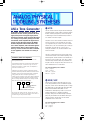
No (1 ~ 128)
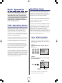
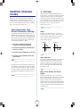
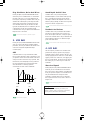
1 VCO
AN1x Tone Generator
The VCO module is where the original sound waveform gets
generated. Although a single oscillator is enough to generate
the basic sawtooth, pulse (square) or other waves required
for different types of musical instrument sounds, the AN1x’s
VCO module is much more complex.
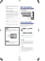
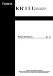
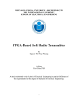
As the AN1x Tone Generator Block Diagram
illustrates, the VCO module generates the basic
signal, then passes it along the signal path to
the MIX/VCF module, which processes the signal
in a variety of ways before passing it on to the
VCA module, which amplifies the signal before
passing it along the signal path to the EFFECT
module comprised of three multi-effects units
and a stereo equalizer, after which the signal is
output from the AN1x's stereo outputs. Along
the way, various real-time and other controllers
can be applied to each module in a variety of
ways.
First, there’s a VCO1 which includes an additional saw2 and
mix wave, and which can be configured with one of three
“sync algorithms” that syncs “master” and “slave” oscillators
within the VCO1, and can be modulated by FM according to
the algorithm. Thus, when the sync is on, the VCO1 is
actually two oscillators in one, and three additional “inner”
waves are available.
The VCO1 is always fixed as the FM carrier, but the carrier
can either be the master or slave oscillator depending on the
selected algorithm. The FM modulator can be selected from a
second VCO (VCO2), the PEG, FEG, LFO1, LFO2 or others.
The Pitch Envelope Generator (PEG) lets you determine how
the pitch of the VCO changes over time, and the LFO can be
used to modulate the VCO to create vibrato.
Oscillators, Filters And Amplifiers
What does it take to make a sound? And how does the
AN1x generate sounds?
In the simplest of terms, there are three basic elements which
make up a sound: pitch, or how low or high it is; tone, or
what its overall quality, or timbre is like; and amplitude, or
how loud the volume level is.
For more information, see as follows:
VCO1 — page 61
VCO2 — page 63
SYNC/FM — page 58
PEG/LFO — page 54
Synthesizers rely on three key electronic components to generate
sounds and electronically imitate the soundwaves of familiar musical
instruments, as well as create entirely unique sounds. In traditional
analog synthesis, the source sound pitch is generated by an
oscillator; its tone is created by a filter; and its volume is determined
by an amplifier. With the AN1x, these three elements are termed
the VCO (voltage controlled oscillator), the VCF (voltage controlled
filter), and the VCA (voltage controlled amplifier).
VCO
VCF
VCA
2 MIX/VCF
The MIX/VCF module is where the mixing of VCO1,
VCO2, Ring Modulator, Noise and Feedback signals
take place, which can then be filtered by the VCF High
Pass Filter (HPF), Low Pass Filter (LPF), Band Pass Filter
(BPF) and Band Eliminate Filter (BEF). You can
determine the cutoff frequency of the VCF, as well as
amount of Resonance, or emphasis around the
frequency cutoff point. The Filter Envelope Generator
(FEG) lets you determine how the timbre of the signal
changes over time, and the LFO1 can be used to
modulate the VCF to create wah.
OUT
The amplifier determines
the volume
The filter determines the timbre
The oscillator creates the source pitch
The “signal path” starts at the VCO, flows to the VCF, then
flows to the VCA. The signal is “processed” at each block, or
“module” along the way to the final output.
For more information, see as follows:
MIX/VCF — page 66
VCF — page 64
HPF — page 67
10
AN1x Tone Generator Block Diagram
CTRL
PEG
LFO2
VCO
VCO1
MIX / VCF
SYNC
MASTER
LFO1
SLAVE
EFFECT
VOLUME
RING
MOD
VARI
MIX
FM
VCO2
VCA
VCF
NOISE
EQ
HPF
FEG
AEG
DLY
REV
FEEDBACK
LPF, HPF, BPF, BEF — page 67
FEG — page 31
PEG/LFO — page 54
RING MODULATOR — page 66
NOISE — page 66
current tempo setting. The 8 Reverb effects include
various Hall, Room and Stage types and more. Delay
and Reverb effects can be configured in a serial or
parallel connection, and specified effects or all effects
(excluding the EQ) can be bypassed at will. Controllers
can be designated to control specific effect parameters.
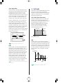
3 VCA
For more information, see as follows:
Vari EF/EQ — page 77
Dly/Rev EF — page 79
EF Bypass — page 80
The VCA module is where the overall output level of
the signal gets determined, as well as the Feedback
level which gets “fed back” to the mixer in the
MIX/VCF module. The Amplitude Envelope Generator
(AEG) lets you determine how the volume of the signal
changes over time, and the LFO1 can be used to
modulate the VCA to create tremolo.
5 CONTROL
Specific parameters of the VCO, MIX/VCF, VCF, VCA
and EFFECT modules, as well as the PEG, LFO1 and
LFO2 can be controlled by many different types of realtime controllers, including [MODULATION] wheel,
[RIBBON] controller X- or Z-axis, the eight assignable
CONTROL knobs, a connected [FOOT CONTROLLER],
keyboard After Touch, and more, including MIDI
Control Change messages received at the MIDI [IN]
terminal.
For more information, see as follows:
VCA — page 68
VOLUME — page 69
FEEDBACK — page 69
AEG — page 32
PEG/LFO — page 54
The AN1x’s Control Matrix and UTILITY SETUP Control
Assign function work together flexibly to give you
complete authority over which on-board or external
controller controls which individual internal or external
parameter.
4 EFFECT
The EFFECT module is where three different types of
programmable effects, as well as programmable 3-band
EQ, can be applied. The 14 Variation Effects include
Chorus, Flanger, Phaser, Auto Pan, Rotary Speaker,
Pitch Change, Aural Exciter, Compressor, Distortion,
Overdrive, Amp Simulator and more. The 5 Delay
effects include Delay LCR, Delay LR, Echo, and Tempo
Delay, which automatically matches the delay time to the
For more information, see as follows:
Control Features — page 49
Control Matrix — pages 51, 73
Utility Control Assign — pages 50, 95
11
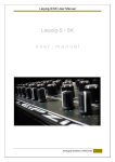
System Examples
Speaker
There are many ways to incorporate the AN1x into
a simple or expanded music system. Following are
a few of the most common examples.
Speaker
Amp
Headphones
The AN1x By Itself
1
2
3
4
5
L
R INPUT
L
R OUTPUT
6
7
8
9
10
11
12
13
14
15
16
L
R
Mixer
At the simplest level, all you need to do is connect
stereo headphones to the [PHONES] jack located on
the rear panel, and you’re ready to go. To use the
AN1x as a stand-alone performance instrument, simply
connect it to amplified speakers and optional FC Foot
Controller and Footswitch pedals as shown in the
diagram at right.
PHONES
L
R OUTPUT
FC4
FC7
AN1x
To avoid possible damage to the speakers or other connected electronic devices, before switching on the
power of any device, make sure the AN1x’s [VOLUME] level and the volume levels of the connected
equipment are set to minimum positions.
Setting Up Your AN1x
The AN1x Control Synthesizer is an ideal stand-alone performancebased electronic musical instrument as well as a powerful component
in an expanded MIDI music system. Following are instructions for
proper setup of the AN1x and connection to external devices.
The AN1x In A MIDI System
It’s easy to create a simple but powerful MIDI music
system with only a few basic components. The
illustration below shows how to connect the AN1x to a
Yamaha QY700 Music Sequencer.
1. After carefully taking your new AN1x out of
the box, place it on a keyboard stand or on
top of a sturdy table or desk.
QY700
2. Next, connect the supplied Yamaha PA-3B (or
equivalent) Adaptor to the AN1x’s [DC IN]
connector located on the rear panel. Then
connect the adaptor to the nearest electrical
outlet.
ASSIGNABLE
MIDI
THRU
OUT
IN
FOOT
SWITCH
FOOT
FOOT
CONTROLLER VOLUME
POWER
ON
OFF
OUTPUT
DC IN
R
MIDI OUT
MIDI IN
MIDI IN
MIDI OUT
PHONES
L/MONO
AN1x
DC IN
You can have the AN1x’s Tempo setting control the
external sequencer’s clock, or the sequencer’s clock
control the speed of the AN1x’s Arpeggiator or Step
Sequencer.
PA-3B Adaptor
3. Before switching on the power, connect any
peripheral devices such as amplified speakers,
FC Foot Controller or Footswitch pedals, or
external MIDI instruments.
For details about assigning AN1x MIDI transmit and receive channels, see page 93. For
details about assigning MIDI channels and other settings for the external sequencer or other
devices which may be connected, consult the owner’s manual for each. For more
information about MIDI, see the APPENDIX, page 109.
Do not attempt to use an AC adaptor other than the PA-3B (or equivalent). Use of an
incompatible adaptor may result in irreparable damage to the AN1x, and could even pose a
serious shock hazard.
Always be sure to disconnect the power adaptor from the electrical outlet when the AN1x is
not in use.
12
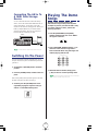
Connecting The AN1x To
A MIDI Data Storage
Device
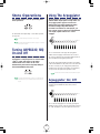
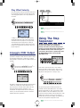
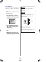
Playing The Demo
Songs
You can connect the AN1x to a MIDI data storage
device, such as the Yamaha MDF2 MIDI Data Filer, in
order to “bulk dump”, or save AN1x voice, Step
Sequencer and other data to floppy disks. This lets you
build up complete libraries of your favorite sounds,
sequences and settings, which you can easily load
back into the AN1x whenever you wish.
The AN1x comes preprogrammed with
demonstration songs which provide dynamic
examples of just how powerful the AN1x really
is. To select and play a Demo, perform the
following operation:
1. Press the [PORTAMENTO] and [LAYER]
switches simultaneously. The word “DEMO”
will appear in the LCD.
MIDI IN
MDF2, etc.
MIDI OUT
DEMO
MIDI OUT
PORTAMENTO
MIDI
MDR
SEO
JOB
UTIL
LAYER
MIDI DATA FILTER
CURSOR
MIDI IN
- FILE DATA +
REC
PAUSE
START/STOP
TEMPO
AN1x
2. Press a PROGRAM CHANGE switch (0 - 9) to
select one of the 10 Demo songs. After a
brief moment the Demo song will begin, and
continue playing until the end.
For information about how to perform Bulk Dump operations, see page 94.
Switching On The Power
PROGRAM CHANGE
VWX
Once all connections have been properly made, you’re
ready to switch on the power and start making music with
your AN1x.
YZ
OTHERS
7
8
9
MNO
PQR
STU
4
5
6
DEF
GHI
JKL
1
2
3
ABC
0
–
NO
YES/ ENTER
1. Set the AN1x’s [VOLUME] knob to minimum
position.
3. When the Demo is finished, simply press
[-/NO] to return to normal operating status.
2. Press the [POWER] switch, located on the rear
panel.
The Demo song will continue playing repeatedly until you stop it. You can stop the
Demo song in the middle of play by pressing [-/NO].
After a brief greeting message which appears in the LCD,
the AN1x will power up and be ready to go.
3. Gradually turn the [VOLUME] knob to the
right while playing the keyboard until you
achieve a comfortable listening level.
VOLUME
13
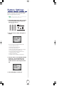
Basic Operation
Selecting Voices
The AN1x comes with 128 voices already preprogrammed and
ready to play. Not only are these voices first-rate and highly
useful in their own right, they form a dynamic living example of
the AN1x’s vast sonic range and power, as well as provide an
excellent basis for study of how voices are constructed.
You'll find the process of getting to know the
AN1x to be fun and inspiring—especially if you
keep a few fundamental things in mind as you
select and play the voices, try out the various
controls and experiment with the panel features
for the first time. Following are some important
aspects about basic operation of the AN1x
which will help you keep things in their proper
context from the very start.
They are also great for use as a starting point for creating your
own voices—by making slight or significant modifications to suit
your needs or taste—which you can then store in the AN1x’s
memory for instant recall at any time.
Of course, if you want to roll up your sleeves and get your
hands on the VCO, VCF and VCA to build up an original
voice from scratch, you can easily initialize a voice (i.e.,
reset each parameter value to its initial setting) and start
from there. The AN1x even provides a few handy
templates which save you time and all the tedious effort by
making all the basic settings for certain types of sounds for
you, so you can pick up from there and concentrate on just
the fun and creative stuff. (See page 30).
AN1x Operating Modes
For the most part, except when performing a specific Store or
MIDI bulk dump operation, the AN1x is basically always in Voice
Play/Edit mode. This means that during play, as you turn the
various CONTROL knobs, change the parameter values or
settings using the Edit matrix [UP/DOWN] switches, select a
Layer mode, etc., you are actually editing the voice. (The “EDIT”
mark will appear in reverse type in the lower left area of the LCD
the first time any voice data is changed.)
Voice Select Operation
However, these changes only remain in effect as long as the voice
is selected, unless you store the newly edited voice using a Voice
Store operation before selecting another voice. If you don’t store
the changes, they will be lost when you select a different voice.
Each of the 128 voices has a Program Number
between 001 and 128. You select a voice using the
PROGRAM CHANGE keypad. There are two ways to
do so, as follows:
The AN1x is a very forgiving instrument, however. A Voice
Recall function (see page 96) lets you retrieve the edited data.
Plus, if you turn the power off before storing an edited voice,
when you turn the power back on the edited parameter
settings will still be retained in the voice edit buffer.
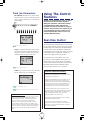
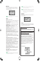
METHOD 1
Input a number between 1 and 128, then press
[ENTER].
PROGRAM CHANGE
VWX
There are various other modes, but these are simply sub-modes of
Voice Play/Edit mode (such as Step Sequencer mode for creating
and editing Voice and User Patterns; see page 37), since virtually
all panel settings—including Scene, Layer, Effects, Arpeggiator,
Step Sequencer settings, and more—are stored as voice data for
each voice (excluding system-related settings).
YZ
OTHERS
7
8
9
MNO
PQR
STU
4
5
6
DEF
GHI
JKL
1
2
3
ABC
0
–
NO
YES/ ENTER
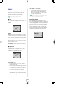
METHOD 2
Press [+] or [–] to increment or decrement through
the voices sequentially.
The voice name, as well as voice Category and
Program Number, appears in the LCD.
14
Voice Categories
Using The Controllers
Voices can be organized into Category types and
assigned a two-letter Category code during the voice
Name operation. For a list of the available Category
types, see page 81.
The AN1x has various on-board controllers which let you
control specific parameters in real-time as you play.
Besides keyboard Initial and After Touch, these include
[PITCH] wheel, [MODULATION] wheel and [RIBBON]
controller, as well as the eight assignable CONTROL
knobs.
Scenes
Each voice has two “Scenes”, or two distinct sounds
available for instant recall at the press of a [SCENE]
switch. Since the specific Scene on/off status is stored
as voice data, when you select a voice an LED beside
one of the [SCENE] switches will light to indicate which
Scene is active. (If both Scene LEDs light, the Scene
Control on status has been stored as part of the voice,
which means you can morph, or cross-fade between
Scenes using the assignable [MODULATION] wheel or
any other assigned continuous controller as you play.)
For more information about Scenes, see page 19.
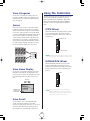
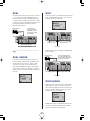
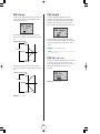
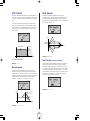
PITCH Wheel
The [PITCH] wheel lets you bend the pitch up or down
by an assignable amount. The pitch bend “depth”
(range) can be different for each Scene, as set in the
Control Matrix.
Bends the pitch up
Knob position settings 2
Algorithm
PEG Decay
Wave
Wave
Attack
VCO1
Level
Attack
Sync Pitch
PEG Depth
Fine
Edge
Ring
Mod
Release
Sustain
ASSIGN 2
FM Depth
PW
PWM Depth
VCF
Cutoff
HPF
Feedback
Sync Pitch
Src
Fine
Sustain
LFO1 Wave
PW
PEG Sw
Pitch
VCO2
Level
ASSIGN 1
Sync
Pmod Sw
Sync Pitch
Depth
Pitch
Decay
Decay
FM Src1
PWM Depth
PWM Src
Reso
nance
VCF
Type
Volume
LFO1 Dly
PWM Src
Fmod
Depth
FEG
Depth
Noise
Level
FM Src2
PmodDepth
Bends the pitch down
LFO2 Spd
PmodDepth
Vel
Sens
PITCH
Key
Track
Vel Sens
Amod Depth
ASSIGN 6
ASSIGN 5
Edge
ASSIGN 4
ASSIGN 3
LFO1 Spd
Port Time
Release
ASSIGN 7
ASSIGN 8
CTRL
The pitch bend range can be different for each Scene in each voice. You can also
use the [PITCH] wheel to control other parameters. For information, see page 51.
Knob position settings 1
Algorithm
PEG Decay
Wave
Wave
Attack
VCO1
Level
Attack
Sync Pitch
PEG Depth
Pitch
Pitch
Decay
VCO2
Level
FM Depth
PW
PWM Depth
VCF
Cutoff
HPF
Feedback
ASSIGN 5
Fine
Fine
Sustain
Ring
Mod
ASSIGN 2
LFO1 Wave
PW
PEG Sw
Sustain
Decay
ASSIGN 1
Sync
Pmod Sw
Sync Pitch
Depth
PWM Depth
VCF
Type
Volume
FM Src1
PWM Src
Edge
Noise
Level
Release
SCENE
Release
ASSIGN 4
LFO1 Dly
PWM Src
Fmod
Depth
FEG
Depth
Amod Depth
ASSIGN 6
Port Time
Edge
ASSIGN 3
LFO1 Spd
Reso
nance
Sync Pitch
Src
ASSIGN 7
FM Src2
PmodDepth
LFO2 Spd
PmodDepth
Vel
Sens
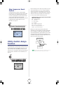
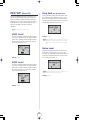
MODULATION Wheel
Key
Track
Vel Sens
ASSIGN 8
The [MODULATION] wheel lets you apply varying
amounts of modulation to the sound as you play,
depending on assignment by the Utility Control Assign
function (see page 50) or in the Control Matrix (see
page 51).
Voice Name Display
As you edit a voice by turning the knobs or changing
parameters in the Edit menu, the information in the
screen changes accordingly. To display the voice name
and number in the LCD at any time, press [-] or [+]
once.
Maximum
Press once
–
NO
or
YES/ ENTER
Minimum
MODULATION
Indicates a voice
has been edited
but not stored.
You can also assign volume, pan or one of many other parameters to be
controlled by the [MODULATION] wheel. For information, see page 95. The
[MODULATION] wheel can also be used to “morph” between Scenes when the
Scene Control function is activated. For information, see page 20.
Voice Recall
If you’re editing a voice, and inadvertently select
another voice before performing a Voice Store
operation, or simply change your mind, you can recall
the most recently edited voice data using the Voice
Recall function. For more information, see page 96.
15
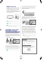
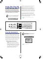
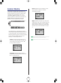
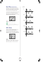
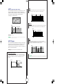
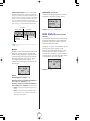
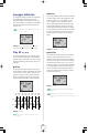
RIBBON Controller
When you set the [EDIT ROTARY] switch to the 5th position
(SEQ EDIT/SETUP menu), the CONTROL knobs will be
dedicated to the event parameters of the various steps
(beats) of the Step Sequencer.
The [RIBBON] controller lets you control two different
assignable parameters as you play. You can control
one parameter by sliding your finger along the X-axis,
and another by applying pressure to the Z-axis. You
can assign parameters to the [RIBBON] controller using
the Utility Assign Control function (see page 50) or the
Control Matrix (see page 51).
Knob
Event
1-8 / 9 -16
Step Hold
Pattern
Bank
Base Unit
No
Length
LoopType
Ctrl No
SEQ
Store
SEQ
EDIT /SETUP
Apply pressure
Z-axis
In this situation, no LED will be lit in the KNOB
PARAMETER GROUP section, and the name of the current
step event parameters will appear in the LCD when you
turn or press a knob.
Maximum
Minimum
X-axis
KNOB PARAMETER GROUP
Sync Pitch
Src
You can assign different parameters to the [RIBBON] controller for each voice. For
information, see page 75.
Port Time
Edge
Noise
Level
Release
Release
To activate the Z-axis you must apply considerable pressure. A light touch will only
apply to the X-axis.
SYNC/FM
PEG/LFO
VCO1
VCO2
VCF
MIX /VCF
VCA
ASSIGN
Edge
ASSIGN 4
When you release your finger from the [RIBBON] controller, the value may remain
at the same position as at the time of release, or reset to the center position
depending on the Control Matrix setting. (See page 73.)
Simply pressing a KNOB PARAMETER GROUP switch will
revert the status back to normal tone generator parameter
control, as will selecting a different Edit menu with the
[EDIT ROTARY] switch. As long as the [EDIT ROTARY]
switch is still set to the SEQ EDIT/SETUP menu, however,
you can press the selected KNOB PARAMETER GROUP
switch again to revert to Step Sequencer control by the
knobs (i.e., you can toggle back and forth between knob
parameter control and step event data edit by pressing the
switch.)
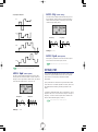
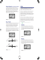
CONTROL Knobs And
Parameter Groups
Which parameter is edited by each CONTROL knob for
each Scene depends on which KNOB PARAMETER
GROUP switch is currently selected, indicated by a lit LED
to the left of it. Pressing a CONTROL knob (push-switch) or
turning a knob will cause its parameter name and value to
display in the LCD.
For more information about the KNOB PARAMETER GROUP switches, see page 16.
For more information about the CONTROL knobs, see page 16. For information
about the Step Sequencer, see page 37.
Selected CONTROL knob parameter
Selected parameter group
Foot Controllers
KNOB PARAMETER GROUP
Sync Pitch
Src
The AN1x features [FOOT CONTROLLER], [FOOT VOLUME],
and [FOOTSWITCH] jacks for connecting various foot
pedals, each of which can be assigned to control one of
many types of available on-board and external parameters.
Port Time
Edge
SYNC/FM
PEG/LFO
VCO1
VCO2
VCF
MIX /VCF
VCA
ASSIGN
Edge
Noise
Level
Release
Release
ASSIGN 4
For more information about assigning controllers, see page 49.
Layer Modes And Portamento
When you select a voice the [ASSIGN] switch will
automatically be selected (unless the [EDIT ROTARY] switch
is set to SEQ EDIT/SETUP), which lets you access the eight
parameters assigned to the respective CONTROL knobs.
One of six Layer modes can be assigned to each voice by
pressing the [LAYER] switch, and Portamento on/off status
can be set by pressing the [PORTAMENTO] switch.
DEMO
For more information about the Utility Control Assign function, see pages 50, 95.
PORTAMENTO
LAYER
STORE
ARPEGGIO/ SEQ
For more information about Layer modes, see page 22. For more information
about portamento, see page 24.
16
AN1x Quick Tour
This section provides a “hand’s on” journey through the key features you’ll access regularly as you
select voices, tweak sounds and adjust settings for the various parameters.
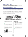
Exploring The Factory-set Voices
Taking the time to systematically explore various aspects of the 128 factory-set voices is an excellent way to get a thorough
understanding of the AN1x’s sonic range and power. It’s also a natural way to quickly familiarize yourself with some of the
fundamental operations you’ll use during performance as well as in voice, Arpeggiator, Step Sequencer and Free EG creation
and editing sessions.
Try the simple operations which follow as you select and play each preset voice, and take note of what happens to the sound
as you change the various settings. If, along the way, you stumble upon a sound you want to keep, simply perform a Voice
Store operation (see page 98). If, however, you mess up a sound too much, there’s no need to worry: Just reselect the same
voice to retrieve the original sound data and start over again! Unless you perform a Voice Store operation, no changes you
make will be permanent. Even if you do decide to store a voice, you need not worry about losing any of the factory-set
voices permanently, because the entire bank can be recalled (see page 100).
PHONES
DC IN
R
L / MONO
POWER
FOOT
FOOT
VOLUME CONTROLLER
FOOT
SWITCH
IN
PEG Decay
Sync Pitch
Depth
PEG Sw
Sync Pitch
Src
Wave
Pitch
Pitch
Fine
Fine
Edge
Attack
VCO1
Level
Decay
VCO2
Level
Sustain
Ring
Mod
Release
VOLUME
Sustain
Decay
ASSIGN 1
Sync
Pmod Sw
ASSIGN 2
LFO1 Wave
FM Depth
PW
PWM Depth
PW
VCF
Cutoff
HPF
Feedback
SCENE
PEG Depth
Wave
Attack
CTRL
Sync Pitch
ASSIGN 5
PWM Depth
VCF
Type
Volume
FM Src1
PWM Src
PWM Src
Fmod
Depth
ASSIGN 7
Ctrl Matrix
Param
Set No
Layer
Pan
Separate
EF
Bypass
Name
Cursor
Mode
Poly
Port
LFO Rst
Tempo
Split Pnt
Vari EF/ EQ
Param
Data
Vari EF
Dry:Wet
Length
Track
Track No
Param
Scene Sw
Track Job
Rec
Copy
MIDI
Ptn Tx Ch
Arpeggio
Subdivide
Play EF
Swing
Source
Depth
Dly/ Rev EF
Param
Data
Unison
Detune
VOICE
SCENE SETUP
Char
VOICE
COMMON
Undo
VOICE
FREE EG
Edge
Noise
Level
ASSIGN 4
LFO1 Dly
FEG
Depth
Amod Depth
ASSIGN 6
THRU
Port Time
Release
ASSIGN 3
LFO1 Spd
Reso
nance
OUT
MIDI
OUTPUT
Algorithm
FM Src2
PmodDepth
SYNC/FM
PEG/ LFO
VCO1
VCO2
LFO2 Spd
VWX
YZ
OTHERS
7
8
9
MNO
PQR
STU
4
5
6
DEF
PmodDepth
VCF
MIX / VCF
Key
Track
VCA
ASSIGN
Vel
Sens
Track Common
LoopType
Trigger
PROGRAM CHANGE
KNOB PARAMETER GROUP
1
GHI
2
0
DEMO
JKL
VOICE
Velocity
GateTime ARPEGGIO /SEQ
Type/No
KbdMode
Hold
SceneSw
Knob
Event
1-8 / 9 -16
Step Hold
Pattern
Bank
No
Base Unit
Length
LoopType
Ctrl No
SEQ
Store
SEQ
EDIT /SETUP
System
Mstr Tune
Kbd Trans
Kbd Vel
MIDI
Tx Ch
Rx Ch
DeviceNo
Local
BulkDump
Ctrl
Device
Ctrl No
UTILITY
SETUP
3
ABC
PORTAMENTO
LAYER
STORE
ARPEGGIO /SEQ
–
NO
Vel Sens
Common
Arp /SEQ
Key Track
YES/ ENTER
ASSIGN 8
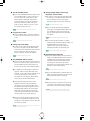
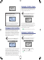
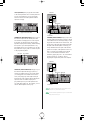
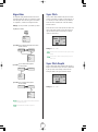
3 Compare Scenes, and morph between Scenes
using Scene Control.
● When you select a voice, the LED beside the
[SCENE 1] or [SCENE 2] switch (or both LEDs) will
be lit, indicating the Scene status which was stored
as voice data. Press each switch to compare the
difference between the sound of Scene 1 and
Scene 2.
1 Select a voice.
● Use the PROGRAM CHANGE keypad to select a
voice (1 - 128).
For information about selecting voices, see Basic Operation, page 14.
2 Check LCD status.
● When you select a voice, first take a look at the
information which appears in the LCD, such as Poly
mode (“POLY”, “MONO”, “LEGATO”), Layer mode
(“SINGLE”, “UNISON”, “DUAL”, “SPLIT”, etc.), and
whether the Arpeggiator (“ARP”) or Sequencer
(“SEQ”) is on. This reveals the fundamental nature
of a voice at-a-glance.
● Press both [SCENE] switches simultaneously to
activate the Scene Control function, then roll the
[MODULATION] wheel forward and back to
morph, or cross-fade between Scenes as you play.
For more information about Scenes and Scene morphing, see page 19.
This area displays Poly mode status
This area displays Layer mode status
This area displays Arpeggiator/
Sequencer on/off and hold status
17
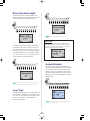
4 Turn the CONTROL knobs.
● Press a KNOB PARAMETER GROUP switch and turn
each CONTROL knob as you play each Scene to
hear how it affects the sound. There are eight
different groups of parameters assigned to the
knobs at the factory. These let you edit the tone
generator parameters as printed on the panel
beside each knob. Notice how easy it is to edit
and drastically change the voice.
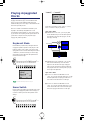
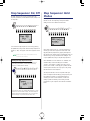
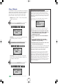
8 Change arpeggio Tempo, Pattern Type,
Subdivision, and Hold status.
● To speed up or slow down the Arpeggiator pattern
(or sequence), set the [EDIT ROTARY] switch to the
VOICE COMMON menu and press Tempo
[UP/DOWN] until you achieve the desired rate.
For more information about Tempo, see page 77.
● To try out the 30 different preset Arpeggiator
pattern types, set the [EDIT ROTARY] switch to the
VOICE ARPEGGIO/SEQ menu and press the
Type/No [UP/DOWN] switch and step through
each pattern.
For more information about using the CONTROL knobs, see page 26.
5 Compare Layer modes.
● Press the [LAYER] switch to compare the difference
of each of the six Layer modes as you play, one at
a time.
For more information about the Type/No parameter, see page 34.
● To hear how the timing resolution of a pattern
changes with the 10 different Subdivide settings, set
the [EDIT ROTARY] switch to the VOICE
ARPEGGIO/SEQ menu and press Arpeggio
Subdivide [UP/DOWN] to step through each.
For more information about Layer modes, see page 22.
6 Change Poly mode setting.
● To hear how the keyboard Poly setting affects how
the voice can be played, set the [EDIT ROTARY]
switch to the VOICE SCENE SETUP menu and press
the Poly [UP/DOWN] switch to select POLY,
MONO or LEGATO. Then play the keyboard.
For more information about Arpeggio Subdivide, see page 34.
9 Change Effects and adjust EQ.
● To hear the different Variation and EQ effects and
settings, set the [EDIT ROTARY] switch to the VOICE
COMMON menu and press Vari EF/EQ Param
[UP/DOWN] and Data [UP/DOWN] switches
accordingly. Also press the Vari EF Dry:Wet
[UP/DOWN] to change the balance between “dry”
(normal) and “wet” (effected) signals.
For more information about Poly mode, see page 72.
7 Turn [ARPEGGIO/SEQ] on and off.
● If the voice uses the Arpeggiator (“ARP” appears in
the LCD) or Sequencer (“SEQ” appears in the LCD),
press the [ARPEGGIO/SEQ] switch to turn it off
and hear how the voice sounds without the pattern.
For more information about Vari EF/EQ, see page 77.
● Pay attention to how the arpeggio or sequence is
triggered—either across the entire length of the
keyboard, or only to the left of the Split Point. In the
case of the Step Sequencer, some voices are
programmed to let you trigger a different pattern
from each key to the left of the Split Point.
● To hear the different Delay and Reverb effects and
settings, press Dly/Rev EF Param [UP/DOWN] and
Data [UP/DOWN] switches accordingly.
For more information about Dly/Rev EF mode, see page 79.
● Set the [EDIT ROTARY] switch to the VOICE
ARPEGGIO/SEQ menu and press KbdMode
[UP/DOWN] once to confirm the setting which
determines how the pattern is triggered. Next, set
the [EDIT ROTARY] switch to the VOICE SCENE
SETUP menu and press Poly [UP/DOWN] and
compare the way the different Poly mode settings
affect the pattern as you play the keyboard.
● To bypass specific or all effects and hear how the
voice sounds in its pristine state, press EF Bypass
[UP/DOWN] and change the status accordingly.
EF Bypass is a system parameter, and therefore will remain as you set it
regardless of which voice is selected. For more information, see page 80.
● If the voice does not use the Arpeggiator or Step
Sequencer, press [ARPEGGIO/SEQ] to turn on the
Arpeggiator or Step Sequencer and hear how notes
and chords are affected.
For more information about the Arpeggiator, see page 33. For information about
the Step Sequencer, see page 37.
18
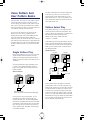
Selecting Scenes
And Scene Morphing
Assignable Real-time Controllers
You can assign specific parameters to the assignable
controller of your choice, including the eight CONTROL
knobs, [MODULATION] wheel, [RIBBON] controller (X-axis
and Z-axis) and keyboard After Touch, as well as (optional)
[FOOT VOLUME], [FOOT CONTROLLER] and
[FOOTSWITCH] pedals. Controller and parameter
assignments are made using the Control Matrix (see page
73) and the Utility Control Assign function (see page 95).
The AN1x’s Scene select and play functions offer
an exciting range of sophisticated and
convenient real-time sound control options that
let you express yourself musically in completely
unique ways. The [SCENE] switches let you select
a Scene or activate the Scene Control function.
For more information about controllers, see Using The Control Features, page 49.
Parameters Stored In Each Scene
•
•
•
All parameter group CONTROL knob position settings
(except for the [ASSIGN] group).
VOICE SCENE SETUP Menu Mode and Control Matrix
(excluding common) parameter settings.
VOICE COMMON menu Vari EF Dry:Wet settings.
Scene Memories
Each voice has two Scene memories, each of which can
have a different edit using the CONTROL knobs. Either
Scene can be recalled at any time during play by pressing
[SCENE 1] or [SCENE 2]. An LED to the left of the selected
switch will light to indicate the active Scene.
Knob position settings 2
Algorithm
PEG Decay
Wave
Wave
Attack
VCO1
Level
Attack
Sync Pitch
PEG Depth
Fine
Edge
Ring
Mod
Release
Sustain
ASSIGN 2
FM Depth
PW
PWM Depth
VCF
Cutoff
HPF
Feedback
Sync Pitch
Src
Fine
Sustain
LFO1 Wave
PW
PEG Sw
Pitch
VCO2
Level
ASSIGN 1
Sync
Pmod Sw
Sync Pitch
Depth
Pitch
Decay
Decay
PWM Depth
Reso
nance
VCF
Type
Volume
FM Src1
PWM Src
LFO1 Dly
PWM Src
Fmod
Depth
FEG
Depth
Noise
Level
FM Src2
PmodDepth
LFO2 Spd
PmodDepth
Vel
Sens
Key
Track
Vel Sens
Amod Depth
ASSIGN 6
ASSIGN 5
Edge
ASSIGN 4
ASSIGN 3
LFO1 Spd
Port Time
Release
ASSIGN 7
ASSIGN 8
CTRL
Knob position settings 1
Algorithm
PEG Decay
Wave
Wave
Attack
VCO1
Level
Attack
Sync Pitch
PEG Depth
Pitch
Fine
Fine
Edge
VCO2
Level
Sustain
Ring
Mod
Release
Sustain
ASSIGN 2
LFO1 Wave
FM Depth
PW
PWM Depth
VCF
Cutoff
HPF
Feedback
ASSIGN 5
Sync Pitch
Src
Pitch
ASSIGN 1
PW
PEG Sw
Decay
Decay
Sync
Pmod Sw
Sync Pitch
Depth
PWM Depth
Reso
nance
VCF
Type
Volume
FM Src1
PWM Src
Noise
Level
SCENE
ASSIGN 4
LFO1 Dly
PWM Src
Fmod
Depth
FEG
Depth
Amod Depth
ASSIGN 6
Edge
Release
ASSIGN 3
LFO1 Spd
Port Time
ASSIGN 7
FM Src2
PmodDepth
LFO2 Spd
PmodDepth
Vel
Sens
Key
Track
Vel Sens
ASSIGN 8
Due to the virtually unlimited number of results possible by
selecting KNOB PARAMETER GROUP switches and turning
the CONTROL knobs, each of the two Scenes can be as
similar or radically different as you want. This gives you
two specific sounds to choose from at any time within each
of the 128 voices, at the simple press of a [SCENE]
switch.
Scenes are especially handy for creating slight variations
on the same sound for use during different parts of a
song—say, one with fast attack that cuts through the mix
during rhythmic phrases, and one with a slower attack
that’s more suitable for a pad. And of course, if the two
Scenes are completely different from each other—say one
sound prepared for verse and chorus, and another for a
solo break—it’s a lot simpler to switch back and forth
between Scenes than it is to switch between voices,
especially under the pressure of a live situation.
19
Scene Control
Scene Edit Buffers
When you select a voice, the two Scenes are loaded into the
Scene edit buffers. Since each Scene has its own buffer, you
can “work” on each Scene separately. For example, if
[SCENE 1] is selected and you edit its parameters by turning
the knobs, this data will be maintained in Scene 1 even if
you select [SCENE 2] and start editing it. When you switch
back to Scene 1, it will recall your edited data (and not the
original Scene 1 data stored with the voice).
The Scene Control function lets you “morph”, or cross-fade
between the two Scenes by rolling the assignable
[MODULATION] wheel, or using an assignable Foot
Controller or any other continuous controller.
For information about assigning controllers, see page 95.
The procedure for activating the Scene Control function is
as follows:
Scene
Tone
Generator
CTRL
1. Press both [SCENE] switches simultaneously.
The LEDs to the left of both switches will light
to indicate that Scene Control is active.
Scene
SCENE
Scene Edit
Buffers
Control knobs
1-8
CTRL
There’s also a Scene Control buffer, where parameter
changes by moving the [MODULATION] wheel (as well as
CONTROL knob positions when Scene Control is active) take
place. This sound can be stored in either Scene edit buffer at
any time using the Scene Store operation.
SCENE
2. Roll the [MODULATION] wheel forward and
back (or use a Foot Controller, etc.) as you
play.
Scene
Scene 2 settings
Scene Control
Buffer
Tone
Generator
Algorithm
Scene 2
Sync Pitch
Src
Fine
Fine
Edge
VCO2
Level
Sustain
Ring
Mod
Release
ASSIGN 2
LFO1 Wave
FM Depth
PW
PWM Depth
VCF
Cutoff
FM Src1
PWM Depth
PWM Src
VCF
Type
Volume
LFO1 Dly
PWM Src
Fmod
Depth
FEG
Depth
ASSIGN 6
Edge
Noise
Level
ASSIGN 4
FM Src2
PmodDepth
LFO2 Spd
PmodDepth
Vel
Sens
Key
Track
Vel Sens
Amod Depth
ASSIGN 5
Port Time
Release
ASSIGN 3
LFO1 Spd
Reso
nance
HPF
Feedback
SCENE
Sustain
Decay
ASSIGN 1
PW
Control knobs
1-8
PEG Sw
Pitch
Decay
Attack
Scene
Sync Pitch
Depth
Pitch
VCO1
Level
VOLUME
CTRL
PEG Depth
Wave
Attack
Sync
Pmod Sw
Scene Edit
Buffers
Sync Pitch
PEG Decay
Wave
ASSIGN 7
ASSIGN 8
Scene 1 settings
Algorithm
Sync Pitch
PEG Decay
Fine
Fine
Edge
VCO2
Level
Sustain
Ring
Mod
Release
ASSIGN 1
ASSIGN 2
LFO1 Wave
FM Depth
PW
PWM Depth
VCF
Cutoff
PWM Depth
VCF
Type
Volume
FM Src1
PWM Src
Edge
Noise
Level
ASSIGN 4
LFO1 Dly
PWM Src
Fmod
Depth
FEG
Depth
Amod Depth
ASSIGN 6
ASSIGN 5
Port Time
Release
ASSIGN 3
LFO1 Spd
Reso
nance
HPF
Feedback
SCENE
Sustain
Decay
PW
MODULATION
Sync Pitch
Src
Pitch
Decay
Sync
Pmod Sw
CTRL
PEG Sw
Pitch
VCO1
Level
VOLUME
Scene 1
Sync Pitch
Depth
Wave
Attack
Attack
Since Scene editing, as well as Scene Store, Load and Swap
operations (see pages 21, 22), are taking place in the Scene
edit buffers, you need not worry about losing your original
Scene data as stored with the selected voice, unless you
perform a Voice Store operation to the same voice location.
PEG Depth
Wave
ASSIGN 7
FM Src2
PmodDepth
LFO2 Spd
PmodDepth
Vel
Sens
Key
Track
Vel Sens
ASSIGN 8
The minimum value of the [MODULATION] wheel (or Foot
Controller, etc.) plays Scene 1; the maximum value plays
Scene 2; any position between the two extremes (between
a range of 0 and 127) will play a blend of both Scenes
accordingly.
However, since the Scene buffer is volatile, you will lose your
edited Scene data unless you perform a Voice Store
operation before selecting another voice.
For information about performing a Voice Store operation, see page 98.
Maximum
Halfway
Minimum
20
MODULATION
MODULATION
MODULATION
Scene 1 setting
Scene 1/2
equal balance
Scene 2 setting
Depending on how different each Scene is, a considerable
number of parameters may get changed simultaneously as
you do the cross-fade. As such, you have an enormous
palette of sound textures available which you can apply in
real-time as you play. Also, you can select KNOB
PARAMETER GROUP switches and turn the CONTROL
knobs to edit the data during the Scene Control. All
parameter changes when both [SCENE] switches are
activated take place in the Scene Control edit buffer.
Confirming Controller Assigned To Scene Control
You can confirm at any time which controller is assigned to
perform Scene Control. Simply press and hold both [SCENE]
switches, and the name of the currently assigned controller
will display in the LCD.
As you morph between the two Scenes and turn the
CONTROL knobs, you may create a killer sound you
simply must save before risking losing it. Performing a
Scene Store operation lets you store it to one of the Scenes
right then and there.
For information about assigning a controller for Scene Control, see page 95.
Scene Store Function
During Scene Control, Control Matrix settings and some of the Switch parameters
(e.g., VCF Type, LFO Wave, VCO Wave, etc.) will not change. For these
parameters, the Scene 1 settings will remain in effect.
The Scene Store function lets you store the data in one Scene
Edit buffer to the other, or the data created during Scene
Control to either of the Scene edit buffers.
Scene Control In DUAL And SPLIT Modes
1. Hold [STORE] and press the [SCENE 1] or
[SCENE 2] switch, depending on which one
you want to store the current Scene setting
into. “SURE?[Y/N]” flashes in the LCD.
Depending on whether the Layer mode is set to DUAL or
SPLIT, the Scene Control will morph in different ways.
In DUAL mode, the Scene Control will morph from the Scene
1 sound to the Scene 2 sound.
Layer mode = DUAL
CTRL
Scene 2
STORE
SCENE
Scene Control
Edit Buffer
2. Press [YES/ENTER] to execute the Scene Store
operation, or [NO] to cancel it.
Scene 1
In SPLIT mode, the Scene Control will morph from the Scene
1 sound to the Scene 2 sound when the keyboard is played
to the left of the Split Point only. When the keyboard is
played to the right of the Split Point, only the Scene 2 sound
will be played.
Since the Scene Store function stores the data to a Scene edit buffer, be sure to
execute a Voice Store operation before selecting another voice.
Layer mode = SPLIT
SPLIT POINT
Scene Control
Edit Buffer
Scene 1
Scene 2
For more information about Layer modes, see page 22.
21
Scene Load Function
Selecting Layer Modes
The Scene Load function lets you load Scene data from a
Scene in any voice to the corresponding Scene in the
currently selected voice. This lets you, for example, load
the Scene 1 parameters of one voice to Scene 1 of the
currently selected voice, and load the Scene 2 parameters
of another voice to Scene 2 of the currently selected voice.
The LAYER switch is used for selecting a Layer
mode from the six available. Every time you
press the switch, a different Layer mode is
selected. The selected Layer at the time of a
Voice Store operation is saved as voice data.
DEMO
1. Hold [SCENE 1] (or [SCENE 2]) and enter the
number of the voice whose Scene data you
want to copy. The selected voice number
flashes in the LCD.
PORTAMENTO
LAYER
STORE
ARPEGGIO/ SEQ
Each Layer mode determines how Note On messages from
either the AN1x’s keyboard or external MIDI devices (as
received at the AN1x’s MIDI [IN] terminal) are handled.
Depending on which Layer mode is selected, either one or
both Scenes will be played, and the Scene Control
function will behave in specific ways. The selected Layer
also affects available polyphony, and determines
multitimbral status.
2. Press [YES/ENTER] to execute the Scene Load
operation, or [NO] to cancel it.
Layer Modes
Data which is loaded:
•All knob parameter settings (excluding [ASSIGN] group)
•VOICE SCENE SETUP Mode and Control Matrix parameters
•VOICE COMMON Vari EF Dry:Wet parameter
SINGLE
This is the normal play mode for a voice. The sound is
determined by the data of the currently selected Scene.
In this mode the AN1x plays with maximum 10 notes
polyphony.
Scene Swap Function
The Scene Swap function lets you exchange the data in
one Scene edit buffer with the other.
1. Hold [STORE] and press both [SCENE 1] and
[SCENE 2] switches. “SURE?[Y/N]” flashes in
the LCD.
UNISON
CTRL
This mode is great for getting those “fat” analog-type
sounds of the legendary vintage synths. In Unison
mode, the data of the currently selected Scene is
multiplied. Polyphony is determined by the Poly mode
setting (see page 72). For example, if Poly mode is set
to “mono” or “legato”, then one Note On message will
use five notes of polyphony; if it is set to “poly”, then
one Note On message will use two notes of polyphony.
STORE
SCENE
2. Press [YES/ENTER] to execute the Scene Swap
operation, or [NO] to cancel it.
Data which is exchanged:
•All knob parameter settings (excluding [ASSIGN] group)
•VOICE SCENE SETUP Mode and Control Matrix parameters
•VOICE COMMON Vari EF Dry:Wet parameter
•VOICE FREE EG Track SceneSw parameter
•VOICE ARPEGGIO/SEQ Common SceneSw parameter
The Unison Detune function (see page 76) lets you decide the detuning for the
Unison in order to fatten the sound.
22
DUAL
SPLIT
This mode layers the two sounds of Scene 1 and Scene
2—i.e., it plays both Scenes simultaneously. In this
mode, the AN1x is capable of multitimbral play (max.
2 sounds), where an external MIDI sequencer or device
can play each Scene on separate MIDI channels, as set
by the UTILITY SETUP Rx Ch (Receive Channel)
parameter (see page 93).
In this mode, Scene 1 is assigned to the keys to the left
of the variable Split Point (see page 77), and Scene 2
is assigned to the keys to the right.
External sequencer
QY300
Two incoming MIDI
signals play each Scene
independently across the
entire keyboard according
to Rx Ch settings.
MUSIC SEQUENCER
MIDI OUT
MIDI IN
AN1x
Plays Scene 1 sound
Plays Scene 2 sound
Scene 1 range = MIDI ch. 1
SPLIT POINT
Scene 2 range = MIDI ch. 2
In SPLIT mode the AN1x is capable of multitimbral play
(max. 2 sounds).
To select a Scene for MIDI channel assignment, simply press a [SCENE] switch.
External sequencer
DUAL UNISON
QY300
Two incoming MIDI signals play
each scene independently over a
range determined by the Split Point,
according to Rx Ch settings.
MUSIC SEQUENCER
MIDI OUT
In this mode, each Dual layer plays in Unison (one
Note On message uses five notes of polyphony) when
the Poly mode is set to “mono” or “legato”. If both
Scenes are set to “poly”, the result is the same as
DUAL mode. Multitimbral play from an external MIDI
source (max. 2 sounds) is also possible, as set by the
UTILITY SETUP Rx Ch (Receive Channel) parameter (see
page 93).
AN1x
MIDI IN
Scene 1 range = MIDI ch. 1
Scene 2 range = MIDI ch. 1
SPLIT POINT
SPLIT UNISON
In this mode, each Scene on each side of the variable
Split Point plays in Unison (One Note On message
uses five notes of polyphony) when Poly mode is set to
“mono” or “legato”. If both Scenes are set to “poly”,
the result is the same as SPLIT mode.
Multitimbral play from an external MIDI source (max. 2
sounds) is also possible, determined by the UTILITY
SETUP Rx Ch (Receive Channel) settings.
23
Portamento Play
Layer Parameters
The AN1x features Layer parameters in the VOICE SCENE
SETUP menu which let you detune the Unison or Dual layers
when UNISON mode or DUAL mode is selected, or separate
the panning between the two layers when UNISON mode,
DUAL mode or SPLIT mode is selected. For more information,
see page 76.
Portamento is an effect commonly used in singing or when
playing a bowed instrument (glissando), where the sound
is carried in a continuous glide from one note to the next,
through all the intermediate pitches.
Key pressed C1
C2
Normal play
Pitch glides from
note to note
Key pressed C1
C2
Portamento
The portamento is applied not only to the AN1x’s voice as
audio output from the internal tone generator, portamento
data is also output from the MIDI [OUT] terminal, which
means it can affect a voice of an external tone generator
assigned to the same MIDI channel as the AN1x, or be
recorded as Control Change data in an external MIDI
sequencer.
Turning PORTAMENTO
On And Off
Pressing the [PORTAMENTO] switch turns the portamento
on or off. Portamento on/off status is stored as voice data.
DEMO
PORTAMENTO
LAYER
STORE
ARPEGGIO/ SEQ
Pressing [PORTAMENTO] outputs a Control Change
message via the MIDI [OUT] terminal, which can be
recorded as Control Change data in an external MIDI
sequencer.
You can designate the assignable Footswitch to turn the
portamento on and off by foot, using the UTILITY SETUP
Control function (see page 95).
24
Selecting
Parameter Groups
Setting Portamento Time
You can determine the Portamento time by pressing
[PEG/LFO] and turning CONTROL knob 4.
Sync Pitch
Src
The KNOB PARAMETER GROUP switches
determine which group of tone generator
parameters you can edit by turning the
CONTROL knobs. You can change the voice
drastically by editing the various parameters.
Simply press a switch to access a group of
parameters. The selected switch will be indicated
by a lit LED to the left of it.
Port Time
Edge
Edge
Noise
Level
Release
Release
ASSIGN 4
When the [PORTAMENTO] switch is turned off, “– – –” will flash in the LCD.
KNOB PARAMETER GROUP
For more information, see page 56.
Selecting Portamento
Modes
There are various Portamento modes available depending
on Poly mode setting. These are accessed by the VOICE
SCENE SETUP menu.
Mode
Poly
Port
LFO Rst
Ctrl Matrix
Param
Set No
Source
Depth
Layer
Pan
Separate
Unison
Detune
SYNC/FM
PEG/LFO
VCO1
VCO2
VCF
MIX /VCF
VCA
ASSIGN
The name of each parameter in the group is printed on the
panel next to the knob by which it is edited, color coded
and arranged in relation to each KNOB PARAMETER
GROUP switch. A description of each parameter group,
along with available parameters and settings available
within each group, is provided in the REFERENCE section.
VOICE
SCENE SETUP
For details, see as follows:
1PEG/LFO — page 54
2SYNC/FM — page 58
3VCO1 — page 61
4VCO2 — page 63
5VCF — page 64
6MIX/VCF — page 66
7VCA — page 68
(ASSIGN — page 70)
CTRL
For more information, see page 73.
PEG
LFO2
VCO
VCO1
MIX/ VCF
SYNC
MASTER
LFO1
SLAVE
VCA
EFFECT
VOLUME
RING
MOD
VARI
EQ
FM
VCO2
NOISE
FEG
AEG
DLY
REV
FEEDBACK
For details about assigning parameters to CONTROL knobs, see page 95. For
information about the AN1x’s tone generator, see page 10.
25
Using The
CONTROL Knobs
If the [EDIT ROTARY] switch is set to positions 1 - 4 or
position 6, when you select a voice the [ASSIGN] switch
will automatically be selected (the LED beside it will light),
which means the group of parameters assigned to the
knobs by the UTILITY SETUP menu Control function can be
edited or controlled by turning the CONTROL knobs. To
access another group of knob parameters, simply press a
KNOB PARAMETER GROUP switch.
The eight CONTROL knobs give you direct access
to dozens of tone generator parameters that let
you coax literally an unlimited range of sounds
from the AN1x in real-time. They also let you
access and edit the individual events in each
step of the Step Sequencer (when the [EDIT
ROTARY] switch is set to the SEQ EDIT/SETUP
menu).
Algorithm
PEG Decay
Sync Pitch
PEG Depth
Sync Pitch
Depth
PEG Sw
Sync Pitch
Src
Wave
Wave
Pitch
Pitch
Fine
Fine
Edge
Attack
VCO1
Level
Decay
VCO2
Level
Sustain
Ring
Mod
Release
Attack
Sustain
Decay
ASSIGN 1
Sync
Pmod Sw
ASSIGN 2
LFO1 Wave
FM Depth
PW
PWM Depth
PW
VCF
Cutoff
HPF
Feedback
FM Src1
PWM Depth
PWM Src
Reso
nance
VCF
Type
Volume
During tone generator or sequence event parameter editing,
a horizontal 11-segment “knob data graph” appears in the
lower area of the LCD. When you press a knob’s push-switch
for data confirmation (before turning the knob), the data
graph provides you with a visual reference of the parameter
value in relation to the current physical position of the knob.
Port Time
Edge
Noise
Level
ASSIGN 4
LFO1 Dly
PWM Src
Fmod
Depth
FEG
Depth
Amod Depth
ASSIGN 6
ASSIGN 5
The Knob Data Graph
Release
ASSIGN 3
LFO1 Spd
For more information about the knob parameters, see page 54.
FM Src2
PmodDepth
LFO2 Spd
PmodDepth
Vel
Sens
Key
Track
Vel Sens
ASSIGN 7
ASSIGN 8
The CONTROL knobs are assignable, so you can
designate a specific parameter to be controlled by each
knob. You can use the Control Matrix to designate each
knob parameter for each Scene in each voice. Plus, you
can use the UTILITY SETUP menu Control function to
designate specific Control Change parameters to be
controlled by each knob when the [ASSIGN] switch is
selected, which not only is routed to the internal tone
generator, but is output via the MIDI [OUT] terminal, and
therefore can be used to simultaneously control an external
MIDI device.
Current knob position Actual value (flashing)
A flashing segment in the data graph indicates the actual
value of the parameter, whereas shaded segments to the left
or right of the flashing segment indicate the current physical
position of the knob. As you turn the knob to the left or right,
the data graph will move left or right in accordance with the
knob movements.
Coarse/Fine Edit
You can edit CONTROL knob parameters in coarse or fine
increments and decrements, depending on how you turn the
knob. The knob data graph will display differently for each
method.
When you turn a knob to edit a parameter, its parameter
name and value will automatically appear in the LCD, and
the knob data graph will track knob movements
accordingly. If you simply press a knob (push-switch)
without turning it, the parameter name and value will
appear in the LCD for visual confirmation, without
changing its value.
Sync Pitch
Src
Simply turning a knob will increase or decrease the
parameter value in coarse (large) amounts. In this case, the
flashing indicator in the knob data graph will be canceled.
Turning a knob while pressing it will increase or decrease the
parameter value in fine (small) amounts. In this case, the
flashing indicator in the knob data graph will position as you
turn the knob, and will remain flashing when you release the
knob.
Port Time
Edge
Edge
Noise
Level
Release
Release
ASSIGN 4
Turning a knob left decreases numeric values (or scrolls
toward the top of a list of available parameters), and
turning a knob right increases numeric values (or scrolls
toward the bottom of a list of available parameters).
For information about assigning controllers, see page 95.
26
Assigning Parameters
To Knobs
Step Sequencer Event Edit
If you set the [EDIT ROTARY] switch to the SEQ EDIT/SETUP
menu (position 5), or if you select a voice when the [EDIT
ROTARY] switch is already set there, no LED will be lit beside
a KNOB PARAMETER GROUP switch, and turning a
CONTROL knob will edit the selected event data of the
Sequencer step assigned to that knob.
You can assign one of many available Control Change
parameters to each knob. After pressing the [ASSIGN]
switch, these parameters will be available for edit in realtime using the CONTROL knobs.
Knob assignments are made using the Control function
(Device and Control Number) parameters located in the
UTILITY SETUP menu. When you press [ASSIGN] and turn
a CONTROL knob, the MIDI Control Change data is sent
to both the internal tone generator as well as to MIDI
[OUT], where it can control external devices. The Control
function assignments are system parameter settings, which
means they will remain as set and be available regardless
of which voice is selected.
When you turn a knob to edit an event, the step event name
and value (and step number) will automatically appear in the
LCD, and the knob data graph will track knob movements
accordingly. Also, if you simply press a knob (push-switch)
without turning it, the information will display in the LCD for
confirmation.
Pressing a KNOB PARAMETER GROUP switch will activate its
group of tone generator parameters (its LED will light), and
pressing the same switch again will return to Step Sequencer
edit status. Setting the [EDIT ROTARY] switch to another
position will also disengage Step Sequencer edit.
For more information about the Step Sequencer, see page 37.
You can also assign various other parameters to the
knobs using the Control Matrix located in the VOICE
SCENE SETUP menu, which only affects parameters for
the internal tone generator (as well as incoming MIDI
messages). And since Control Matrix parameters are
voice settings, they are stored as voice data, which
means that each voice can have customized knob
assignments for each Scene!
For details on how to assign Control function parameters to the CONTROL knobs,
see page 95. For details on how to assign Control Matrix parameters to the
CONTROL knobs, see page 73.
For a list of available parameters which can be assigned to each CONTROL knob,
see the separate Data List book.
27
Using The Panel
Edit Matrix
Tempo
Layer
Pan
Separate
Dly / Rev EF
Param
Data
EF
Bypass
Name
Cursor
LFO Rst
Split Pnt
Vari EF/ EQ
Param
Data
Vari EF
Dry:Wet
Length
Track
Track No
Param
Scene Sw
Track Job
Rec
Copy
Arpeggio
Subdivide
Play EF
Swing
Velocity
Key Track
Layer
Pan
Separate
Unison
Detune
Vari EF/EQ
Param
Data
Vari EF
Dry:Wet
Dly/Rev EF
Param
Data
EF
Bypass
Name
Cursor
Char
VOICE
COMMON
Length
Track
Track No
Param
Scene Sw
Track Job
Rec
Copy
Undo
VOICE
FREE EG
Arpeggio
Subdivide
Ctrl Matrix
Param
Set No
Key Track
Source
Depth
VOICE
Common
Arp /SEQ
Type/No
KbdMode
Hold
SceneSw
MIDI
Ptn Tx Ch
Play EF
Swing
Velocity
Knob
Event
1-8 / 9 -16
Step Hold
Pattern
Bank
No
Base Unit
Length
LoopType
Ctrl No
SEQ
Store
SEQ
EDIT /SETUP
System
Mstr Tune
Kbd Trans
Kbd Vel
MIDI
Tx Ch
Rx Ch
DeviceNo
Local
BulkDump
Ctrl
Device
Ctrl No
UTILITY
SETUP
GateTime ARPEGGIO /SEQ
1 Voice Menus
Ctrl Matrix
Param
Set No
Port
Track Common
LoopType
Trigger
LFO Rst
Split Pnt
3 Utility Menu
2 Step Sequencer Menu
1 Voice Menus
Select a menu (1 - 6)
Mode
Poly
Port
Tempo
Track Common
LoopType
Trigger
The AN1x’s panel matrix of Edit menus gives
you quick and easy access to hundreds of
parameter settings. All you have to do is set the
[EDIT ROTARY] switch to one of the six menus
and press the parameter value [UP/DOWN]
switch located beneath the name of the
parameter you want to edit.
VOICE
SCENE SETUP
Mode
Poly
Source
Depth
Unison
Detune
VOICE
SCENE SETUP
Char
VOICE
COMMON
Undo
VOICE
FREE EG
The four Voice menus are primarily dedicated to parameters
which affect the tone generator.
VOICE SCENE SETUP Includes Scene Mode and Control
Matrix parameters plus Layer-related parameters for the
voice.
VOICE
Common
Arp /SEQ
Type/No
KbdMode
Hold
SceneSw
MIDI
Ptn Tx Ch
Knob
Event
1-8 / 9 -16
Step Hold
Pattern
Bank
No
Base Unit
Length
LoopType
Ctrl No
SEQ
Store
SEQ
EDIT /SETUP
System
Mstr Tune
Kbd Trans
Kbd Vel
MIDI
Tx Ch
Rx Ch
DeviceNo
Local
BulkDump
Ctrl
Device
Ctrl No
UTILITY
SETUP
GateTime ARPEGGIO /SEQ
VOICE COMMON Includes Tempo, Split Point, Effect and
voice naming parameters which are common to both Scenes,
and Variation Effect Dry:Wet balance parameter which can
be set for each Scene.
Press this area to increment settings (hold to scroll)
Press this area to decrement settings (hold to scroll)
Press once to display information in LCD
VOICE FREE EG Includes Trigger and Length setting, Track
and Parameter select, plus recording and other parameters
related to the Free EG function.
Press the [UP/DOWN] switch once to display the name of
the parameter and current value setting in the LCD. Press
the upper or lower area of the switch repeatedly to
increment or decrement through the settings, or hold the
upper or lower area of the switch to scroll through the
settings.
VOICE ARPEGGIO/SEQ Includes common and specific
parameters related to the Arpeggiator and Step Sequencer.
For a description of each parameter and available settings, see the REFERENCE
section, page 72. For information about the Arpeggiator, see page 33.
2 Step Sequencer Menu
The SEQ EDIT/SETUP menu includes Knob event and
sequence editing-related parameters, as well as Pattern Bank
and Number select, and other parameters related to the Step
Sequencer.
For a description of each parameter and available settings, see the REFERENCE
section, page 89. For information about the Step Sequencer, see page 37.
3 Utility Menu
The UTILITY SETUP menu includes “global” parameters,
including System tuning and keyboard transpose and velocity
parameters, MIDI channel transmit, receive and other
settings, and Control function assignment-related parameters.
For a description of each parameter and available settings, see the REFERENCE
section, page 92. For more information about the Control function, see page
50.
28
Editing Voices
3. Edit the various tone generator parameters
for each Scene, using the KNOB PARAMETER
GROUP switches and CONTROL knobs.
If you’ve read through all the preceding
sections, and especially if you’ve been trying out
the various features along the way, you should
have a pretty solid grounding in how the AN1x
creates and enhances sound, as well as how the
various controls work to manipulate the many
features. This section provides an overview of
the steps required for the procedure of editing a
voice, along with the key procedures required to
build up your own voices from scratch.
KNOB PARAMETER GROUP
Algorithm
PEG Decay
Sync Pitch
8
9
STU
4
5
6
DEF
GHI
JKL
1
2
3
VCO1
Level
Decay
VCO2
Level
Sustain
Ring
Mod
Release
2. Set the status of Layer mode with the [LAYER]
switch and Poly mode (located in the VOICE
SCENE SETUP menu).
ASSIGN 2
LFO1 Wave
FM Depth
PW
PWM Depth
HPF
Mode
Poly
Port
LFO Rst
ARPEGGIO/SEQ
Ctrl Matrix
Param
Set No
Source
Depth
FM Src1
PWM Depth
PWM Src
VCF
Type
Reso
nance
Volume
Noise
Level
ASSIGN 4
LFO1 Dly
PWM Src
Fmod
Depth
FEG
Depth
FM Src2
LFO2 Spd
PmodDepth
PmodDepth
Vel
Sens
Key
Track
Vel Sens
Amod Depth
ASSIGN 6
Edge
Release
ASSIGN 3
LFO1 Spd
Port Time
ASSIGN 7
ASSIGN 8
VOICE
SCENE SETUP
Mode
Poly
Port
LFO Rst
Layer
Pan
Separate
Unison
Detune
Tempo
Split Pnt
Vari EF/ EQ
Param
Data
Vari EF
Dry:Wet
Dly / Rev EF
Param
Data
EF
Bypass
Name
Cursor
Char
VOICE
COMMON
Length
Track
Track No
Param
Scene Sw
Track Job
Rec
Copy
Undo
VOICE
FREE EG
Arpeggio
Subdivide
Ctrl Matrix
Param
Set No
Key Track
Source
Depth
VOICE
Common
Arp /SEQ
Type/No
KbdMode
Hold
SceneSw
MIDI
Ptn Tx Ch
Play EF
Swing
Velocity
Knob
Event
1-8 / 9 -16
Step Hold
Pattern
Bank
No
Base Unit
Length
LoopType
Ctrl No
SEQ
Store
SEQ
EDIT /SETUP
System
Mstr Tune
Kbd Trans
Kbd Vel
MIDI
Tx Ch
Rx Ch
DeviceNo
Local
BulkDump
Ctrl
Device
Ctrl No
UTILITY
SETUP
GateTime ARPEGGIO /SEQ
5. Store the voice data to a voice memory
location (1 - 128) using the Voice Store
operation (see page 98).
DEMO
STORE
Sustain
Decay
Track Common
LoopType
Trigger
LAYER
Sync Pitch
Src
4. Depending on your needs, use the panel Edit
matrix to designate effects configuration and
settings, record real-time knob movements
for one or more parameters using the 4-track
Free EG function, designate Arpeggiator
settings, create a Step Sequence, assign
Control Matrix sets, and set any other voice
parameters.
YES/ ENTER
PORTAMENTO
PEG Sw
Attack
–
NO
Sync Pitch
Depth
Edge
ASSIGN 5
ABC
0
PEG Depth
Fine
Feedback
OTHERS
YZ
PQR
ASSIGN
Fine
VCF
Cutoff
PROGRAM CHANGE
7
MIX /VCF
Pitch
PW
1. Select a voice using the PROGRAM CHANGE
keypad.
MNO
VCF
VCA
Pitch
Sync
Pmod Sw
VWX
VCO2
Wave
ASSIGN 1
The AN1x is so naturally intuitive, the procedure for
editing a voice is extremely simple. There are only a few
basic steps, as follows:
PEG/LFO
VCO1
Wave
Attack
Voice Edit Procedure
SYNC/FM
Layer
Pan
Separate
Unison
Detune
VOICE
SCENE SETUP
Parameters which you can edit at any time but which are not stored as voice data
include system-related parameters accessible from the UTILITY SETUP menu, as
well as Effect Bypass status (VOICE COMMON menu) and MIDI Pattern Transmit
Channel (VOICE ARPEGGIO/SEQ menu). As such, they will remain as set
regardless of which voice is selected.
29
1. VCO Edit
CREATING ORIGINAL
VOICES
Pressing the [VCO1] KNOB PARAMETER GROUP
switch gives you access to the main voltage controlled
oscillator parameters, which let you select the basic
waveform and determine the fundamental pitch of the
sound. Pressing the [VCO2] switch gives you access to
the second oscillator, which contains the same set of
parameters as VCO1, and lets you add extra
dimension to the voice.
Following is an overview of the key procedures required to
build up your own voices from scratch. For step-by-step
examples of how to create specific types of voices,
including analog synth classics like Synth Bass and Synth
Brass, as well as traditional Electronic Organ and Electric
Piano voices and more, see page 101.
No sound will be produced if the VCO1 Level or VCO2 Level settings in the
[MIX/VCF] group are too low.
Tone Generator and
Panel Parameter Editing
Wave
By turning CONTROL knob 1 you can select the
waveform for the VCO1 oscillator—from a list which
includes sawtooth, square (pulse) and a variety of
others—which determines the fundamental
characteristics of the voice.
By editing the tone generator parameters you can
determine the fundamental characteristics of the voice.
These are accessed by pressing a KNOB PARAMETER
GROUP switch and turning specific CONTROL knobs.
There are four key steps in the process of editing the
tone generator parameters, as follows:
Saw Wave
Pulse Wave
1. VCO edit to select the fundamental
waveform and determine the pitch
2. VCF edit to apply filtering and determine
the tone, or timbre
3. VCA edit to apply amplification to the voice
For details about the available waves, see page 61.
4. LFO edit to apply modulation to the VCO,
VCF and VCA
Pitch And Fine
By turning CONTROL knobs 2 (Pitch) and 3 (Fine) you
can determine the fundamental pitch of the wave.
Using both oscillators you can slightly “detune” the
pitch of each with the Fine parameter to fatten the
sound, or create intervals by setting different Pitch
parameters for each.
Tone generator parameter editing affects the selected Scene (loaded in the Scene
edit buffer) or the Scene Control sound (in the Scene Control buffer). For details,
see page 20.
By editing the various panel Edit menu parameters you
can determine a voice's keyboard and Scene related
modes, configure effect types and settings, record Free
EG tracks, create and assign Step Sequencer patterns
or configure the Arpeggiator. (For details, see page
71.)
For details about the Pitch and Fine parameters, see pages 61, 62.
Edge, Pulse Width And Pmod
Depth
Certain panel parameters apply to individual Scenes or both Scenes equally for the
voice. For details about each menu and available parameters, see page 72.
By turning CONTROL knob 4 you can adjust how
sharp or smooth the "edge" of the wave is. CONTROL
knob 5 lets you determine the width of the wave's
pulse to control the amount of harmonics present.
CONTROL knob 8 lets you adjust the Pitch Modulation
Depth to create a vibrato effect. Other parameters let
you apply modulation to the pulse width with the LFO1
and other waves.
For details about the Edge, Pulse Width and Pmod Depth parameters, see pages
62, 63.
30
2. VCF Edit
Sync Algorithm
Pressing the [SYNC/FM] KNOB PARAMETER GROUP
switch lets you use the CONTROL knobs to access the
parameters which affect the "master" and "slave"
oscillators which are part of the VCO1, as well as
configure how the FM (Frequency Modulation) signal is
applied to the master and/or slave oscillators. When
the "sync" is enabled VCO1 literally becomes two
oscillators in one, with the slave synced to the master.
Pressing the [VCF] KNOB PARAMETER GROUP switch
gives you access to the voltage controlled filter
parameters, which let you determine the characteristics
of the tone, or timbre of the voice, and configure the
Filter Envelope Generator (FEG).
VCF Cutoff And Resonance
By turning CONTROL knob 5 you can set the cutoff
frequency of the VCF Type (as designated in the
MIX/VCF group), which determines the point at which
specified frequencies are passed or cut off—i.e.,
filtered out. CONTROL knob 6 lets you boost the
harmonics near the cutoff frequency to apply
resonance. These two parameters are critical in
determining the timbre of the voice.
By turning CONTROL knob 1 you can configure the
sync Algorithm, which either turns off the sync and
makes only the FM signal available, or lets you apply
the FM signal to either master or slave or both
oscillators. CONTROL knob 2 lets you access the Sync
Pitch parameter to create a difference in pitch between
the master and slave oscillators and control the
resulting harmonic interval. Other parameters available
let you apply modulation to the VCO1 oscillators with
the LFO1 and other waves.
Range passed
Cutoff range
VCO
VCO1
SYNC
MASTER
Cutoff frequency
SLAVE
Frequency
VCF Type = Low Pass Filter
FM
VCO2
FEG
CONTROL knobs 1-4 let you determine the Attack,
Decay, Sustain and Release values, respectively, to give
you precision control over how the timbre of the voice
changes over time—from when a key is pressed, held,
then released, and subsequently how long it takes for
the sound to terminate. CONTROL knob 7 lets you set
the FEG Depth, or range of movement of the cutoff
frequency.
For details about the [SYNC/FM] parameters, see page 58.
PEG
Pressing the [PEG/LFO] KNOB PARAMETER GROUP
switch let you use the CONTROL knobs to access
parameters which control the Pitch Envelope Generator
(PEG), which determines how the pitch of a voice
changes over time—from when a key is pressed, held,
then release, and how long it takes for the sound to
terminate. CONTROL knob 2 lets you set the PEG
Depth, or pitch in semitones. CONTROL knob 1 lets
you adjust the PEG Decay, or time required for the
sound to reach its basic pitch from the PEG Depth
setting. CONTROL knob 3 lets you set the PEG Switch
to determine which VCO the PEG is applied to.
Cutoff frequency
Time
Sustain
Attack
For more information about PEG Depth, PEG Decay, and PEG Switch parameters,
see page 55.
Key on
Decay
Release
Key off
For more information about [VCF] parameters, see page 64.
31
Ring Modulator, Noise And Mixer
Amod Depth And Vel Sens
Pressing the [MIX/VCF] KNOB PARAMETER GROUP
switch lets you use CONTROL knobs 1-4 to determine
the levels of the VCO1, VCO2, Ring Modulator and
Noise signals, respectively. CONTROL knob 5 lets you
determine the cutoff frequency of the High Pass Filter
applied to the signal which is output from the mixer,
and CONTROL knob 6 lets you select the VCF filter
type (LPF, HPF, BPF, BEF) which is controlled by the VCF
Cutoff frequency (in the [VCF] parameter group).
CONTROL knob 7 lets you adjust the Filter Modulation
Depth to create a wah effect.
CONTROL knob 7 lets you adjust Amplitude
Modulation Depth to create a tremolo effect by using
LFO1. CONTROL knob 8 lets you set the Velocity
Sensitivity to determine the amplitude of the VCA in
relation to playing strength, to either increase dynamic
range with a heavier or lighter touch.
For more information about Amod Depth and Vel Sens parameters, see page 70.
Feedback And Volume
CONTROL knob 5 lets you determine the feedback
level which is output from the VCA and then "fed
back" into the input of the mixer, causing the signal to
become fat. CONTROL knob 6 lets you determine the
overall output level from the VCA before the signal
passes to the Effect block.
For more information about [MIX/VCF] parameters, see page 66.
3. VCA Edit
Pressing the [VCA] KNOB PARAMETER GROUP switch
gives you access to the voltage controlled amplifier
parameters, which let you determine the volume of the
sound and configure the Amplitude Envelope
Generator (AEG).
For more information about Feedback and Volume parameters, see page 69.
4. LFO Edit
The Low Frequency Oscillator is an oscillator which
generates low frequency signals to let you apply a
modulation signal to specific aspects of the voice. For
example, applying the LFO to the VCO creates vibrato,
applying it to the VCF creates wah, and applying it to
the VCA creates tremolo. The AN1x has two separate
LFOs which give you a wide range of control over
modulation.
AEG
CONTROL knobs 1-4 let you determine the Attack,
Decay, Sustain and Release values, respectively, to give
you precision control over how the volume of the voice
changes over time—from when a key is pressed, held,
then released, and subsequently how long it takes for
the sound to terminate. The diagrams which follow
show the difference in envelope generator
characteristics for some common instruments.
Wave And Speed
Pressing the [PEG/LFO] KNOB PARAMETER GROUP
switch lets you use CONTROL knob 5 to select the
LFO1 Wave from 21 types available. CONTROL knob
6 lets you adjust LFO1 Speed, and CONTROL knob 7
lets you determine the LFO1 Delay time of the
modulation. CONTROL knob 8 lets you adjust the
LFO2 Speed for the LFO2 wave, which is fixed to a
triangle wave.
Level
Time
Sustain
Attack
Decay
Key on
Piano
Release
For more information about LFO parameters, see page 54.
Key off
Violin
Storing A Voice
As you edit your voice, depending on whether you're
working on Scene 1, Scene 2 or the Scene Control sound,
you may want to perform Voice Store operations.
For more information, see page 68.
32
Store Operations
Using The Arpeggiator
The [STORE] switch is used for performing Voice
Store operations.
The Arpeggiator lets you play arpeggiated chord
patterns at the simple press of a key. There are
30 arpeggio pattern Types to choose from.
Between the 10 Arpeggio Subdivide (timing
resolution) settings, Play Effect Velocity
parameter and number of notes played, you
have a wide range of control and customization
over length, rhythm and feel of a voice’s
arpeggio.
DEMO
PORTAMENTO
LAYER
STORE
ARPEGGIO/SEQ
For information about performing a Voice Store operation,
see page 98.
For information about types of data stored in a voice, see page 9.
Common
Arp /SEQ
Type/No
KbdMode
Hold
SceneSw
MIDI
Ptn Tx Ch
Arpeggio
Subdivide
Play EF
Swing
VOICE
Velocity
GateTime ARPEGGIO /SEQ
For information about Scene-related Store functions, see page 21. For information
about SEQ Store, see page 46.
Turning ARPEGGIO/SEQ
On And Off
You can control which Scene plays the arpeggiated
patterns, turn the Arpeggio Hold function on and off at
will, and even designate an independent MIDI channel on
which to output the Arpeggiator pattern data.
The [ARPEGGIO/SEQ] switch is used to turn the
Arpeggiator or Step Sequencer on and off. Either
“ARP” or “SEQ” will appear in the LCD to
indicate which one is active for the voice,
determined by the Common Arp/SEQ setting in
the VOICE ARPEGGIO/SEQ menu.
The specific Arpeggiator-related parameters are available
in the VOICE ARPEGGIO/SEQ menu, but a few others will
also have a bearing on your arpeggiated performances,
including Tempo and Poly mode settings, and depending
on Layer mode, the Split Point assignment as well.
DEMO
PORTAMENTO
LAYER
STORE
ARPEGGIO/SEQ
For information about each VOICE ARPEGGIO/SEQ menu parameter, see page 85.
For information about the Arpeggiator, see page 33. For information about the
Step Sequencer, see page 37. For information about the Arp/SEQ setting, see
page 85.
Arpeggiator On/Off
The Arpeggiator can only be activated when the Arp/SEQ
parameter (VOICE ARPEGGIO/SEQ menu) is set to
“Arpeggio”.
Common
Arp /SEQ
Type/No
KbdMode
Hold
SceneSw
MIDI
Ptn Tx Ch
Arpeggio
Subdivide
Play EF
Swing
VOICE
Velocity
GateTime ARPEGGIO /SEQ
You can turn the Arpeggiator on and off by pressing the
[ARPEGGIO/SEQ] switch. When the Arpeggiator is turned
on, “ARP” will appear in the lower right area of the LCD.
33
Arpeggio Pattern Types
The 30 arpeggio pattern Types are selected by pressing
Type/No [UP/DOWN]. The available Types are basically
divided into two groups, separated chords (Types 1-15),
and special arpeggios (Types 16-30).
Setting The Arpeggiator Tempo
Common
Arp /SEQ
Type/No
KbdMode
Hold
SceneSw
MIDI
Ptn Tx Ch
Arpeggio
Subdivide
Play EF
Swing
VOICE
Velocity
GateTime ARPEGGIO /SEQ
Set the [EDIT ROTARY] switch to VOICE COMMON and
press Tempo [UP/DOWN] to set the tempo of the
Arpeggiator in BPM (Beats Per Minute).
If you want the clock of an external MIDI sequencer or drum
machine to control the AN1x’s tempo, then set the Tempo to
“MIDI” (the first value located before “40”) so that the two
devices will play in synchronization with each other.
Types 1-15 separate the chords you play in a variety of
ways, either generating arpeggios which occur up, down,
up and down, or randomly—over one, two or four
octaves. Types 16-30 are special types which vary in tone
or add subtle shifts or more complex dynamics and
rhythmic elements to the arpeggio.
Arpeggio Hold Function
For more information about Type/No, see page 85. For a list of available
Arpeggiator Types, see the Arpeggiator Type List in the separate Data List book.
Pressing Hold [UP/DOWN] lets you turn the Arpeggio
Hold function on and off. When Hold is set to "on",
"HOLD" will appear in reverse type in the lower right
corner of the LCD. After triggering the Arpeggiator by
playing the keyboard, the arpeggio will continue playing
automatically when you release the keys, until you switch
the Hold setting to "off", or press [ARPEGGIO/SEQ] to
stop the Arpeggiator. When set to "off", the Arpeggiator
will stop when you release the keys.
Common
Arp /SEQ
Type/No
KbdMode
Hold
SceneSw
MIDI
Ptn Tx Ch
Arpeggio
Subdivide
Play EF
Swing
Arpeggio Subdivide
Pressing Arpeggio Subdivide [UP/DOWN] lets you
designate one of the ten timing subdivision (rhythm
resolution) settings for the Arpeggiator pattern.
Common
Arp /SEQ
VOICE
Velocity
Type/No
KbdMode
Hold
SceneSw
MIDI
Ptn Tx Ch
Arpeggio
Subdivide
Play EF
Swing
VOICE
Velocity
GateTime ARPEGGIO /SEQ
GateTime ARPEGGIO /SEQ
Available Subdivide settings are as follows:
The Arpeggio Hold function is especially useful during live
performances when the Layer mode is set to “SPLIT” and
Keyboard Mode is set to “chrd&norm” (see page 35),
since you can trigger the arpeggio with notes to the left of
the Split Point, and use both hands to play chords or fills to
the right. Arpeggio Hold is also handy when trying out
different Arpeggiator Types or Subdivide settings, and is
literally indispensable for tweaking the tone generator
parameters for your arpeggios with the CONTROL knobs.
3
3/8=q., 1/4=q, 3/16=e., 1/6= h h h , 1/8=e, 3/32=x.,
3
3
1/12= q q q , 1/16=x, 1/24= q q q , 1/32=r
For more information about Arpeggio Subdivide, see page 88.
34
“scne1” or “scne2”
Playing Arpeggiated
Chords
Trying out the various arpeggios is a lot of fun. Turn on the
Arpeggio Hold function, play an even-numbered note
chord, and see how the different pattern Types and
Subdivide settings react. Then play an odd-numbered note
chord and repeat the process.
When the Scene Switch is set to “scne1” or “scne2”,
Scene 1 or Scene 2 will play as follows:
There are a wealth of combinations available at your
fingertips—with relatively straightforward or even
unconventional results awaiting you. And only by rolling
up your sleeves and exploring all the options at hand can
you become an expert at how to get just the right
arpeggio for just the right track.
Layer mode = DUAL
● If KbdMode is set to “chrd”, you can play both
Scenes simultaneously across the entire keyboard.
The selected Scene plays the arpeggio, and the
other plays normally.
Keyboard Mode
Scene 2 only
Press KbdMode [UP/DOWN] to designate how the
Arpeggiator patterns respond to notes played on the
keyboard. Select “chrd” (Chord) if you want to play
arpeggiated chords across the entire keyboard. Select
“chrd&norm” (Chord & Normal) if you want to play
arpeggiated chords to the left of the Split Point and
normal chords to the right.
Common
Arp /SEQ
Type/No
KbdMode
Hold
SceneSw
MIDI
Ptn Tx Ch
Arpeggio
Subdivide
Play EF
Swing
Arpeggiator
Scene 1:
Pad sound
● If KbdMode is set to "chrd&norm", you can play
both Scenes simultaneously across the entire
keyboard. The selected Scene plays arpeggios
when you play chords to the left of the Split Point,
and plays the Dual voice normally when you play
to the right of the Split Point.
VOICE
Velocity
Scene 2:
Decay sound
GateTime ARPEGGIO /SEQ
Layer mode = SPLIT
● If “scne1” is selected and KbdMode is set to
“chrd”, you can play arpeggios with Scene 1 to the
left of the Split Point, and arpeggios with Scene 1
and normal chords with Scene 2 to the right.
For information about setting the Split Point, see page 77.
● If “scne2” is selected and KbdMode is set to
“chrd”, you can play arpeggios with Scene 2 and
normal chords with Scene 1 to the left of the Split
Point, and arpeggios with Scene 2 to the right.
Scene Switch
Press SceneSw [UP/DOWN] to designate which Scene
will play the Arpeggiator pattern. Scenes will play in
accordance with Layer mode and Keyboard Mode
settings.
Common
Arp /SEQ
Type/No
KbdMode
Hold
SceneSw
MIDI
Ptn Tx Ch
Arpeggio
Subdivide
Play EF
Swing
VOICE
Velocity
GateTime ARPEGGIO /SEQ
35
Layer mode = SPLIT
● If “scne1” is selected and KbdMode is set to
“chrd&norm”, you can play arpeggios with Scene
1 to the left of the Split Point, and play normally
with Scene 2 to the right.
Scene 1:
Bass sound
● If KbdMode is set to “chrd”, you can play
arpeggios with Scene 1 to the left of the Split Point,
and play normally with Scene 2 to the right.
Scene 2:
Solo sound
● If KbdMode is set to “chrd&norm”, you can play
arpeggios with Scene 1 to the left of the Split Point
and normal chords to the right.
Scene 1 only
When SceneSw “both” is set in SPLIT mode, depending on selected arpeggio
Type, as well as Split Point setting and the position at which you play the keys,
certain notes of the arpeggiated chords may cross the Split Point, i.e., lower notes
will play Scene 1 and higher notes will play Scene 2.
Arpeggiator
Layer mode = SINGLE
(Same as for “scne1” or “scne2”, page 35.)
● If “scne2” is selected and KbdMode is set to
“chrd&norm”, you can play arpeggios with Scene
2 and normal chords with Scene 1 to the left of the
Split Point, and play normally with Scene 2 to the
right.
Arpeggio Pattern Length
The length of an AN1x arpeggio pattern is determined by
three factors which work together simultaneously: Arpeggio
Type, Arpeggio Subdivide setting, and the total number of
notes you play for an arpeggiated chord.
For example, say you play an arpeggiated pattern with a
four-note chord, such as a C major triad with an octave in
the root. If Subdivide is set to “1/8”, the Arpeggiator breaks
down the chord into 8ths, and then arpeggiates it based on
the Type setting. If Type is set to “UpOct2” the arpeggio will
climb over two octaves, and will repeat after four beats.
Then, if you change Subdivide to “1/16”, the arpeggio will
repeat after 2 beats. Furthermore, if you then change Type to
“UpOct1”, the arpeggio will repeat after only one beat.
Layer mode = SINGLE
● If KbdMode is set to “chrd”, you can play
arpeggios with the selected [SCENE] switch only
(or Scene Control sound) across the entire
keyboard.
● If KbdMode is set to “chrd&norm”, you can play
arpeggios with the sound of the selected [SCENE]
switch only (or Scene Control sound) to the left of
the Split Point and normal chords with the sound of
the selected [SCENE] switch only (or Scene Control
sound) to the right.
Because the number of notes you play in the chord has a
direct relationship on the pattern length based on Subdivide
resolution, sometimes unwanted syncopations may be
generated. As a general rule, you can avoid this by choosing
an even number of chord notes for even-numbered subdivide
resolutions (1/4, 1/8, 1/16 and 1/32) and an odd number
of notes (e.g., three-note or five-note chords) with oddnumbered resolutions (1/6, 1/12, 1/24).
“both”
However, this doesn’t apply for dotted note rhythms (3/8,
3/16 and 3/32). These resolutions are particularly
interesting for odd-numbered beats (e.g., 3/8 or 6/8), so
you will need to play chords with an even number of notes to
correctly play back these three-part rhythms.
As an example, set Type to “UpOct2” and Subdivide to
“3/8” resolution. Playing a triad will place the root note on
the first beat in the 4th bar, generating irregular cycles. A
four-note chord, however, generates symmetrical 4 bar
cycles. The root note will be repeated after the first cycle on
bar 3, after the second cycle on bar 5 and after the third
cycle on bar 7, and so on, always landing on the first beat.
When the Scene Switch is set to “both”, both Scenes
will play as follows:
Layer mode = DUAL
● If KbdMode is set to “chrd”, you can play
arpeggios with Scene 1 and Scene 2 across the
entire keyboard.
In the case of the special Arpeggiator Types (16-30), you will
notice that these aren’t particularly effective with triplet
rhythms. Best results are achieved with a 4/4 beat and a
Subdivide resolution of “1/16”, “1/8” or “1/32”.
● If KbdMode is set to “chrd&norm”, you can play
arpeggios with Scene 1 and Scene 2 to the left of
the Split Point, and play normally with Scene 1 and
Scene 2 to the right.
36
Play Effect Velocity
Ext. TG 2
(Attack sound)
Press the Play Effect Velocity [UP/DOWN] switch to set
the ratio between the lower and higher velocity values
of the Arpeggiator pattern, over a range between 1%
and 200%.
Common
Arp /SEQ
Type/No
KbdMode
Hold
SceneSw
MIDI
Ptn Tx Ch
Arpeggio
Subdivide
Play EF
Swing
Ext. TG 1
(Pad sound)
Rcv. Ch2
Rcv. Ch1
Ptn TxCh2
MIDI TxCh1
Arpeggiator
VOICE
Velocity
GateTime ARPEGGIO /SE
For information about setting the MIDI Pattern Transmit Channel (“MIDI
PtnTxCh”), see page 87.
The MIDI PtnTxCh setting is a system parameter, and will not be saved as voice
data.
Using The Step
Sequencer
A setting of “100%” maintains the original velocity
relationship between the notes. Lower values adjust
velocities downward at playback, and higher values
adjust velocities upward at playback. A setting of
“real” (Real-time) will cause the velocity values of the
pattern to be determined by the velocity at which you
play the keyboard.
The Step Sequencer lets you create your own
16-step looped patterns by setting Note,
Velocity, Gate Time and Control Change event
values for each step (beat) in the sequence using
the CONTROL knobs, where each knob gives
you access to the events in a specific step when
the [EDIT ROTARY] switch is set to the SEQ
EDIT/SETUP menu.
Arpeggio MIDI Output
You can use the MIDI Pattern Transmit Channel (“PtnTxCh”)
parameter to designate a MIDI channel on which to output
the Arpeggiator pattern data, to either play an external
tone generator or record the data into a MIDI sequencer or
computer.
Algorithm
Type/No
KbdMode
Hold
SceneSw
MIDI
Ptn Tx Ch
Arpeggio
Subdivide
Play EF
Swing
PEG Depth
Sync Pitch
Depth
PEG Sw
Sync Pitch
Src
Pitch
Pitch
Fine
Fine
Edge
VCO1
Level
Decay
VCO2
Level
Sustain
Ring
Mod
Release
Attack
Sustain
Decay
ASSIGN 1
Sync
Pmod Sw
ASSIGN 2
LFO1 Wave
FM Depth
PW
PWM Depth
PW
CTRL
Sync Pitch
Wave
Attack
VOLUME
VCF
Cutoff
HPF
Feedback
SCENE
Common
Arp /SEQ
PEG Decay
Wave
PWM Depth
Reso
nance
VCF
Type
Volume
ASSIGN 5
FM Src1
PWM Src
Noise
Level
ASSIGN 4
LFO1 Dly
PWM Src
Fmod
Depth
FEG
Depth
Amod Depth
ASSIGN 6
Edge
Release
ASSIGN 3
LFO1 Spd
Port Time
ASSIGN 7
FM Src2
PmodDepth
LFO2 Spd
PmodDepth
Vel
Sens
Key
Track
Vel Sens
ASSIGN 8
VOICE
Velocity
GateTime ARPEGGIO /SEQ
Each of the 128 voices has its own “Voice” Pattern
memory for storing a single sequence. There is also a
separate bank of 128 “User” Patterns. Patterns can be
triggered from the keyboard in a variety of ways.
Knob
Event
This setting is independent from the MIDI Transmit Channel
(“MIDI Tx Ch”) setting in the UTILITY SETUP menu (see
page 93), but you can either set them both to the same
channel or different channels, depending on your
requirements. The diagram below shows an example of
how they can be set to different channels to control two
different external tone generators.
1-8 / 9 -16
Step Hold
Pattern
Bank
No
Base Unit
Length
LoopType
Ctrl No
SEQ
Store
SEQ
EDIT /SETUP
The specific Step Sequencer-related parameters are
available in the SEQ EDIT/SETUP menu. Also, Pattern
Number, Keyboard Mode, Hold, Scene Switch and Play
Effect parameters in the VOICE ARPEGGIO/SEQ menu
have special functions related to the Step Sequencer. Other
settings which will have a bearing on your sequences
include Tempo and Poly mode settings, and depending on
Layer mode, the Split Point assignment as well.
37
For information about each SEQ EDIT/SETUP menu parameter, see page 89.
Step Sequencer On/Off
Step Sequencer Hold
Modes
The Step Sequencer can only be activated when the
Arp/SEQ parameter (VOICE ARPEGGIO/SEQ menu) is set
to “Step SEQ”.
Common
Arp /SEQ
Type/No
KbdMode
Hold
SceneSw
MIDI
Ptn Tx Ch
Arpeggio
Subdivide
Play EF
Swing
Pressing Hold [UP/DOWN] lets you turn the SEQ Hold
function on and off. Depending on Keyboard Mode
setting, there are two additional Hold modes.
VOICE
Velocity
GateTime ARPEGGIO /SEQ
Common
Arp /SEQ
You can turn the Step Sequencer on and off by pressing
the [ARPEGGIO/SEQ] switch. When the Step Sequencer is
turned on, “SEQ” will appear in the lower right area of the
LCD.
Setting The Step Sequencer Tempo
Vari EF/ EQ
Param
Data
Vari EF
Dry:Wet
Dly / Rev EF
Param
Data
EF
Bypass
Name
Cursor
Char
Hold
SceneSw
MIDI
Ptn Tx Ch
Arpeggio
Subdivide
Play EF
Swing
VOICE
Velocity
GateTime ARPEGGIO /SEQ
When KbdMode is set to “sel&norm” or “sel&shift”, two
additional SEQ Hold mode settings are available:
“mode1”, which triggers a pattern every time a key is
pressed, and “mode2”, which triggers a pattern after the
current sequence finishes, even if you press a key during
the middle of the current sequence.
Set the [EDIT ROTARY] switch to VOICE COMMON and
press Tempo [UP/DOWN] to set the tempo of the Step
Sequencer in BPM (Beats Per Minute).
Split Pnt
KbdMode
When SEQ Hold is set to “on”, “HOLD” will appear in
reverse type in the lower right corner of the LCD. After
triggering the Step Sequencer by playing the keyboard,
the sequence will continue playing automatically when you
release the key, until you switch the Hold setting to “off”,
or press [ARPEGGIO/SEQ] to stop the Step Sequencer.
When Arp/SEQ is set to “Arpeggio”, the various parameters in the SEQ
EDIT/SETUP menu cannot be accessed.
Tempo
Type/No
VOICE
COMMON
The SEQ Hold function, used in conjunction with Layer
mode and Keyboard Mode settings, greatly expands your
live performance options. It’s also indispensable for
searching for Voice and User Patterns, as well as for
editing a pattern or tweaking various tone generator
parameters for your sequence sound with the CONTROL
knobs.
If you want the clock of an external MIDI sequencer or drum
machine to control the AN1x’s tempo, then set the Tempo to
“MIDI” (the first value located before “40”), so that the two
devices will play in synchronization with each other.
38
All editing of the pattern will of course be taking place
in the buffer. If you want, you can use SEQ Store
[UP/DOWN] to store the edited pattern to any User
Pattern bank memory (1 - 128). If you perform a Voice
Store operation, the edited voice will become the new
Voice Pattern for the voice.
Voice Pattern And
User Pattern Banks
In addition to the voice-related data stored in a voice
memory location, each voice has “Voice Pattern” data for
a single Step Sequencer pattern. Since there are 128
voices in memory, the collection of 128 patterns as stored
in the voices is called the Voice Pattern bank. In addition
to the Voice Pattern bank, there is a separate bank of 128
“User Patterns” called the User Pattern bank.
Pattern Select Play
During Pattern Select Play, you can trigger more than
one Step Sequencer pattern from the keyboard. Each
pattern is assigned to a different key. For Pattern Select
Play, the Keyboard Mode parameter (VOICE
ARPEGGIO/SEQ menu) must be set to either
“sel&norm” or “sel&shift”.
The Voice and User Patterns can be played from the
keyboard in a variety of ways, depending on the
Keyboard Mode setting in the VOICE ARPEGGIO/SEQ
menu. The individual Keyboard Mode settings are
explained on page 41, but first let’s take a look at the two
main methods of Step Sequencer play—Single Pattern Play
and Pattern Select Play—and see what’s happening inside
the AN1x’s memory structure as you select, edit and store
patterns.
As the Pattern Play Select diagram illustrates, when you
select a voice with the PROGRAM CHANGE keypad,
Voice Pattern data is loaded into the Voice Pattern edit
buffer, and all 128 User Patterns are loaded into the
User Pattern Edit buffer.
PATTERN SELECT PLAY
Single Pattern Play
During Single Pattern Play, you can play a single Step
Sequencer pattern from the keyboard. For Single
Pattern Play, the Keyboard Mode parameter (VOICE
ARPEGGIO/SEQ menu) must be set to either “norm” or
“shift&norm”.
As the Single Pattern Play diagram illustrates, when
you select a voice with the PROGRAM CHANGE
keypad, Voice Pattern data is loaded into the Voice
Pattern edit buffer.
Voice Bank
User Bank
Voice Patterns (128)
User Patterns (128)
Voice Pattern
Edit Buffer
SINGLE PATTERN PLAY
User Pattern
Edit Buffer (128)
SPLIT POINT
Voice Bank
User Bank
Voice Patterns (128)
User Patterns (128)
#
C 1 to Split Point
C1
Pressing different keys on the keyboard will “select”
different patterns, and C1 will always play the Voice
Pattern for the current voice. C#1 and above will select
and trigger different User Patterns in ascending order
across the Key Code (keyboard notes) up to the Split
Point, based on which User Pattern number is assigned
to C#1. If you set the [EDIT ROTARY] switch to the SEQ
EDIT/SETUP menu and press (Pattern) No [UP/DOWN]
once, the pattern number will appear in the LCD each
time you press the corresponding key.
Voice Pattern Edit Buffer
(Pattern loaded into the Voice Pattern edit buffer will be played)
When you press a key on the keyboard, you are
tiggering the Voice Pattern stored with the voice,
located in the buffer. You can set the [EDIT ROTARY]
switch to the VOICE EDIT SETUP menu and press Bank
[UP/DOWN] to select either the Voice or User Pattern
bank, and every time you press No [UP/DOWN] to
select a pattern number, that pattern will load into the
Voice Pattern edit buffer.
39
Playing Step
Sequencer Patterns
The AN1x comes with 128 Voice Patterns and 128 User
Patterns ready to go. All patterns can be overwritten to
store your own.
Since the triggered Voice and User Patterns are
selected and played from edit buffers, you can edit any
pattern at will—i.e., you can trigger one pattern and
edit it, trigger a second pattern and edit it, go back to
the first one and tweak it some more, and so on, in
order to edit various patterns in context with each
other.
Selecting Pattern Banks
And Numbers
To select a Pattern Bank, set the [EDIT ROTARY] switch
to SEQ EDIT/SETUP and press Bank [UP/DOWN].
During Single Pattern Play, either the Voice or User
Pattern bank can be selected. During Pattern Select
Play, only the User Pattern bank can be selected.
If you want, you can use SEQ Store [UP/DOWN] to
store any edited pattern to any User Pattern bank
memory (1 - 128). If the User Pattern has been edited,
the "All Ptn" (All Patterns) store confirmation message
will appear in the LCD, and you can press
[YES/ENTER] to overwrite all patterns, or press [NO]
to cancel the operation.
Knob
Event
1-8 / 9 -16
Step Hold
Pattern
Bank
No
Base Unit
Length
LoopType
Ctrl No
SEQ
Store
SEQ
EDIT /SETUP
C#1 Assign
C#1 is always the base note assignment for the first User
Pattern to be selected. As shown in the Pattern Select Play
diagram (page 39), if “Usr001” (User 001) is assigned to
C#1, then pressing C#1 selects User Pattern 001, pressing
D1 selects Pattern 002, pressing D#1 selects Pattern 003,
and so on. The User Patterns are always selected in
ascending order according to pattern number (001 - 128).
The C#1 Assign feature lets you “shift” the starting pattern
number. For example, if you assign “Usr003” to C#1, then
pressing C#1 selects User Pattern 003, pressing D1 selects
Pattern 004, pressing D#1 selects Pattern 005, and so on.
To select a Pattern Number, press No [UP/DOWN].
You can select from 128 patterns in each bank.
Keyboard Mode
The Keyboard Mode setting (VOICE ARPEGGIO/SEQ
menu) determines Single Pattern Play (“norm” or
“shift&norm”) or Pattern Select Play (“sel&norm” or
“sel&shift”) status.
To assign a User Pattern number to C#1, set the [EDIT
ROTARY] switch to VOICE ARPEGGIO/SEQ and press
Type/No [UP/DOWN]. Arp SEQ must be set to “Step SEQ”,
and KbdMode must be set to “sel&norm” or “sel&shift”. (See
page 85.)
Common
Arp /SEQ
40
Type/No
KbdMode
Hold
SceneSw
MIDI
Ptn Tx Ch
Arpeggio
Subdivide
Play EF
Swing
VOICE
Velocity
GateTime ARPEGGIO /SEQ
norm (Normal): Lets you play the Voice Pattern
of the currently selected voice at its base pitch from
any key on the keyboard. You can play regular
notes and chords across the keyboard while the
sequence is looping.
User Bank
User Patterns (128)
SPLIT POINT
Triggers current Voice Pattern
User Patterns
Voice Pattern
shift&norm (Shift & Normal): Playing a key to
the left of the Split Point will shift the pitch of the
Voice Pattern accordingly (with C2 as the original
base pitch), and playing keys to the right of the
Split Point will play notes normally, without affecting
the sequence. If you set the Split Point to a very
high setting (above C6, for example), you can shift
the pattern from any key, with C2 as the base pitch
of the programmed pattern.
Base pitch
Normal play
sel&shift (Select & Shift): Playing a key to the
left of the Split Point will trigger (“select”) a specific
User Pattern based on C#1 Assign setting (C1 will
trigger the Voice Pattern for the current voice), and
playing keys to the right of the Split Point will shift
the pitch of the selected pattern accordingly. C4
always determines the base pitch of the selected
pattern. For example, if the Split Point is set to C3,
then C1 plays the Voice Pattern for the selected
voice, and 23 different User Patterns can be
selected by playing keys C#1 ~ B2, and shifted in
pitch by pressing C3 and above, with C4
triggering the original base pitch of the sequence.
SPLIT POINT
User Bank
User Patterns (128)
Shifts pattern
Normal play
sel&norm (Select & Normal): Playing a key to
the left of the Split Point will trigger (“select”) a
specific User Pattern based on C#1 Assign setting
(C1 will trigger the Voice Pattern for the current
voice), and playing keys to the right of the Split
Point will play notes normally, without affecting the
sequence. Each User Pattern will play at its
programmed pitch. If you set the Split Point to a
very high setting (above C6, for example), you can
select a different pattern from any key.
SPLIT POINT Base pitch
User Patterns
Voice Pattern
Shifts pattern notes
When “sel&shift” is selected and the Split Point is assigned above C4, then
sequence pitch can only be shifted above the base pitch.
For more information about Keyboard Mode, see page 86. For information about
assigning the Split Point, see page 77.
41
Base Unit And Length
The Base Unit parameter, together with the current
Tempo setting (see page 77) designates and completes
the timing resolution for the sequence pattern.
Knob
Event
1-8 / 9 -16
Step Hold
Pattern
Bank
No
Base Unit
Length
LoopType
Ctrl No
SEQ
Store
Knob
Event
1-8 / 9 -16
Step Hold
Pattern
Bank
No
Base Unit
Length
LoopType
Ctrl No
SEQ
Store
SEQ
EDIT /SETUP
SEQ
EDIT /SETUP
For more information about Loop Type, see page 91.
Scene Switch
The Scene Switch setting (in the VOICE ARPEGGIO/SEQ
menu) determines whether the Step Sequencer Pattern will
play Scene 1, Scene 2, or both Scenes. The current Scene
status will also affect how the Scenes play.
The Length parameter setting determines the length of
the sequence pattern based on number of steps. One
step is equivalent to one note, so based on the Base
Unit setting, you can also select odd-numbered steps to
create odd-numbered beats (such as setting the Length
to "3" for 3/4-time, or to "5" for 5/4-time), as well as
create completely unconventional rhythms.
Knob
Event
1-8 / 9 -16
Step Hold
Pattern
Bank
No
Base Unit
Length
LoopType
Ctrl No
SEQ
Store
Control Number
SEQ
EDIT /SETUP
The Control Number setting determines the type of
MIDI Control Change message which can be output by
each event upon sequencer play. Once the Control
Number is set, the Control Change event is selected
with (Knob) Event [UP/DOWN], and the value to be
output via each step is edited with the corresponding
CONTROL knob.
For more information about Base Unit and Length, see page 91. Also see the
section on Arpeggio Subdivide, which is similar to Base Unit, page 34.
Knob
Event
1-8 / 9 -16
Step Hold
Pattern
Bank
No
Base Unit
Length
LoopType
Ctrl No
SEQ
Store
SEQ
EDIT /SETUP
Loop Type
The Loop Type parameter lets you determine the type of
loop cycle for the sequence pattern. The pattern always
loops, and you can designate it to loop either forward,
backward, or designate one of two alternating
forward/backward types.
For more information, see page 91. For more information about MIDI Control
Change messages, see page 109.
42
Play Effects
Exploring The Factory-set Patterns
The Play Effect (“Play EF”) parameters let you designate
settings which can permit the Step Sequencer pattern to
obtain a more human “feel”. (Or even a less one, if
that’s what you’re going for!) There are three Play
Effect parameters, Swing, Velocity and Gate Time.
To help get a clearer understanding of how the various Step
Sequencer-related parameters and settings work, you may
want to take some time and systematically examine the
details of some of the factory-set voices which are specially
programmed to demonstrate the power and range of the Step
Sequencer, and change the various settings to analyze the
possible effects.
Swing: Lets you create a “swing” feel by slightly
shifting certain beats.
Common
Arp /SEQ
Type/No
KbdMode
Hold
SceneSw
MIDI
Ptn Tx Ch
Arpeggio
Subdivide
Play EF
Swing
As an example, use the PROGRAM CHANGE keypad to
select “Sq:011 Alan”, then trigger the pattern.
VOICE
Velocity
GateTime ARPEGGIO /SEQ
This voice uses the Hold function, so the pattern will play
repeatedly as you check the various settings, as follows:
1. Notice which Layer mode appears in the LCD.
Check KbdMode and Scene Switch settings, as
well as Play Effect settings in the VOICE
ARPEGGIO/SEQ menu.
2. Check the Split Point in the VOICE COMMON
menu.
Velocity: Lets you set the ratio between lower and
higher velocity values of each step.
Common
Arp /SEQ
Type/No
KbdMode
Hold
SceneSw
MIDI
Ptn Tx Ch
Arpeggio
Subdivide
Play EF
Swing
3. Set the [EDIT ROTARY] switch to the SEQ
EDIT/SETUP menu and check the Base Unit,
Length and Loop Type settings.
VOICE
Velocity
GateTime ARPEGGIO /SEQ
4. Repeat the basic process above for each voice
which uses the Step Sequencer.
While you’re at it, why not go ahead and step through some
of the factory-set Voice and User Pattern while the sequence
is looping? Press (Pattern) Bank [UP/DOWN] to select the
Voice or User Pattern bank, then press (Pattern) No
[UP/DOWN] to select and listen to each pattern.
And don’t be shy about playing around with the different
parameter settings and see what effect they have on the
sequence. If you stumble upon something that sounds good
along the way, you might want to go ahead and store the
edited voice to another voice location before you lose it! If
things get too far out of hand, simply reselect the same voice
with the PROGRAM CHANGE keypad and start over! It
won’t take too long to get a clear understanding of how the
different settings work together to let you create and play
your own hot sequences.
Gate Time: Lets you adjust the note length (the
duration of the note) either shorter or longer, as a
percentage of the original.
Common
Arp /SEQ
Type/No
KbdMode
Hold
SceneSw
MIDI
Ptn Tx Ch
Arpeggio
Subdivide
Play EF
Swing
VOICE
Velocity
GateTime ARPEGGIO /SEQ
For more information about Play Effects and available settings, see page 88.
43
Knob Event Parameters
Step Sequencer Edit
To designate which type of event to edit by the
CONTROL knobs, set the [EDIT ROTARY] switch to the
SEQ EDIT/SETUP menu and press Event [UP/DOWN].
There are four types of events to choose from.
Creating your own Step Sequencer patterns is a simple
and straightforward process. When the [EDIT ROTARY]
switch is set to the SEQ EDIT/SETUP menu, each
CONTROL knob is used to edit Note, Velocity, Gate Time
and Control Change values for a single step.
Note (C-2 ~ G8): Lets you select the note for the step.
First decide the Base Unit and Length for the sequence
pattern. Then, editing each step is simple.
Each knob as positioned on the panel (1-8) relates to the
corresponding sequence step (either 1-8 or 9-16,
respectively). Press 1-8/9-16 [UP/DOWN] to toggle back
and forth between which series of steps are available for
data entry using the eight CONTROL knobs.
Knob
Event
1-8 / 9 -16
Step Hold
Pattern
Bank
No
Base Unit
Length
LoopType
Ctrl No
SEQ
Store
Knob
Event
1-8 / 9 -16
Step Hold
Pattern
Bank
No
Base Unit
Length
LoopType
Ctrl No
SEQ
Store
SEQ
EDIT /SETUP
SEQ
EDIT /SETUP
Simply pressing a CONTROL knob will display the
currently selected step and Knob Event parameter name,
as well as the current parameter value setting, in the LCD.
Turning a knob will edit the value.
Step 1 or 9
Step 2 or 10
Step 3 or 11
Step 4 or 12
Step 5 or 13
Step 6 or 14
Step 7 or 15
Step 8 or 16
Event parameter name:
Select with (Knob) Event
parameter
Step number:
Depends on selected
knob and (Knob)
1-8/9-16 setting
You can choose a note to assign to each step by turning the knobs during Step
Sequencer playback.
Event parameter value:
Turn the knob to edit
Velocity (0 ~ 127): Lets you set the velocity level
for the step.
44
Gate Time (1 ~ 200%): Lets you determine the
note duration for the step.
While Step Hold is active, you can press Event
[UP/DOWN] to select the type of event you want to
edit, then turn the CONTROL knob accordingly.
To turn the Step Hold function off, simply press Step
Hold [UP/DOWN] again and switch it to “off”.
For more information, see page 89.
Control Change (0 ~ 127): Lets you set the
value of the MIDI Control Change message to be
output by the step.
1-8/9-16
Press 1-8/9-16 [UP/DOWN] to choose the step series
within which the step you want to edit is, then press a
CONTROL knob’s push-switch to select a specific step.
Current information about the step will display in the
LCD.
Control Change setting (off, CC1~95, After Touch) is determined by the Control
No (Number) parameter in the SEQ EDIT/SETUP menu. For more information, see
page 91.
Knob
Event
For more information about Event parameters, see page 89.
Step Hold
The Step Hold function is used during step event
editing. When you press Step Hold [UP/DOWN] and
set it to “on”, a single step will play repeatedly, based
on the Tempo and Pattern Base Unit settings, in order
to fine-tune the events for the specific step. This lets you
adjust the various event settings in context with the
speed and resolution of the sequence.
Knob
Event
1-8 / 9 -16
Step Hold
Pattern
Bank
No
Base Unit
Length
LoopType
Ctrl No
SEQ
Store
SEQ
EDIT /SETUP
Each time you press a different CONTROL knob’s push
switch while Step Hold is active, that step will be
played, and its information will appear in the LCD.
Turning a CONTROL knob will edit the current event
value of the selected step.
45
1-8 / 9 -16
Step Hold
Pattern
Bank
No
Base Unit
Length
LoopType
Ctrl No
SEQ
Store
SEQ
EDIT /SETUP
Step Sequencer MIDI
Output
Storing Step Sequences
Depending on whether the Step Sequencer is in Single
Pattern Play or Pattern Select Play status, you can do the
following:
•
You can use the MIDI Pattern Transmit Channel (“PtnTxCh”)
parameter to designate a MIDI channel on which to output
the Step Sequencer pattern data, to either play an external
tone generator or record the data into a MIDI sequencer or
computer.
Perform a Voice Store operation to store the current Voice
Pattern data in the Voice edit buffer as voice data (in
Single Pattern Play status).
For information about performing a Voice Store operation, see page 98.
•
Perform a Sequence Store operation to store the currently
selected pattern to any User Pattern memory (in Single
Pattern Play or Pattern Select Play status).
Common
Arp /SEQ
Type/No
KbdMode
Hold
SceneSw
MIDI
Ptn Tx Ch
Arpeggio
Subdivide
Play EF
Swing
VOICE
Velocity
GateTime ARPEGGIO /SEQ
SEQ Store Operation
Knob
Event
1-8 / 9 -16
Step Hold
Pattern
Bank
No
Base Unit
Length
LoopType
Ctrl No
SEQ
Store
SEQ
EDIT /SETUP
This setting is independent from the MIDI Transmit Channel
(“MIDI Tx Ch”) in the UTILITY SETUP menu (see page 93),
but you can either set them both to the same channel or
different channels, depending on your requirements. The
diagram below shows an example of how they can be set
to different channels to control two different external tone
generators.
1. Press SEQ Store [UP/DOWN] to select the user
pattern location. “SURE? [Y/N]” and “Bank
User” flash alternately in the LCD.
Ext. TG 2
(Attack sound)
Ext. TG 1
(Pad sound)
Rcv. Ch2
Ptn TxCh2
Step
Sequencer
Rcv. Ch1
MIDI TxCh1
2. Press [YES/ENTER] to store the pattern, or [NO]
to cancel the operation
(Depends on Keyboard Mode setting)
For information about setting the MIDI Pattern Transmit Channel (“MIDI
PtnTxCh”), see page 87.
The MIDI PtnTxCh setting is a system parameter, and will not be saved as voice
data.
The SEQ Store operation temporarily stores the pattern currently playing to the
pattern edit buffer, so be sure to perform a Voice Store operation (see page 98)
before selecting another voice.
46
Using The Free EG
The Free EG is extremely flexible. You can record each
parameter in separate track passes, or all tracks
simultaneously in one pass. You can specify the length of
time the Free EG will record or play back, either in
measures (up to eight bars, based on Tempo setting), or
“absolute” time (up to 16.0 seconds), as well as have the
Free EG loop in one of four ways as you hold the keys.
The Free EG is a special 4-track recorder for
recording real-time knob position movements,
one parameter per track. Subsequently, when
you play the voice, the data of the parameter
assigned to each track will automatically change
in accordance with the way you recorded it.
Track Common
LoopType
Trigger
Length
Key Track
Track
Track No
Param
Scene Sw
Track Job
Rec
Copy
Undo
You can copy Free EG data from another track to the
current track, within the same voice as well as from
another voice. And since Free EG track data and settings
are voice parameters, they are stored as voice data when
you perform a Voice Store operation.
VOICE
FREE EG
For information about the Free EG recording procedure, see page 84.
Parameter changes over time (bars or seconds)
ASSIGN 1
ASSIGN 2
ASSIGN 3
ASSIGN 4
ASSIGN 5
ASSIGN 6
ASSIGN 7
ASSIGN 8
Track 1
MIX/VCF
Track 2
SYNC/FM Sync Pitch
Noise Level
Track 3
VCF
Resonance
Track 4
VCF
VCF Cutoff
Values relative to knob movements
Free EG Parameters
Track Common
LoopType
Trigger
There are three categories of Free EG parameters: (1)
Track Common, which includes settings that affect all four
tracks of data for recording and play; (2) Track, or settings
which determine the current Free EG track, the parameter
assigned to each track, and which Scene the Free EG will
play; and (3) Track Job, for recording a track (or all tracks)
and performing track copy operations. Following is a brief
description of parameters available in each category.
Length
Key Track
Track
Track No
Track Common Parameters
Trigger: Determines how the track playback is
triggered, either by pressing a key on the AN1x’s
keyboard after selecting a voice (“free”), a Note
On message from the keyboard or an external MIDI
device (“kbd”), or by a Note On message from
either the keyboard, an external device, the
Arpeggiator or Step Sequencer (“all”).
For more information, see page 81.
47
Param
Scene Sw
Track Job
Rec
Copy
Undo
VOICE
FREE EG
Track Parameters
Loop Type: Determines the type of loop for play
of the Free EG sequence, either to play once but
not loop (“off”), to loop forward from beginning to
end (“fwd”), to loop forward from middle to end
(“half”), to Alternate, i.e., loop from beginning to
end then end to beginning (“ alt”), or to Half
Alternate, i.e., loop from middle to end then end to
middle (“ half”).
Track No (Track Number): Selects a Free EG
track (“Trk1” ~ “Trk4”).
Track Common
LoopType
Trigger
Length
Key Track
Track
Track No
Param
Scene Sw
Track Job
Rec
Copy
Undo
VOICE
FREE EG
For more information, see page 82.
Length: Determines the time for recording and
play of the Free EG sequence, either by number of
measures (between 1/2 and 8 bars; determined by
Tempo setting) or in absolute time (between 1.0
and 16.0 seconds).
For more information, see page 83.
Param (Parameter): Determines which knob
parameter will be played by the data in the track.
For more information, see page 83.
For more information, see page 82.
Only one parameter can be selected for a track. For information about available
parameters, see the separate Data List book.
Key Track: Determines the length of the Free EG
in relation to notes played on the keyboard, using
C3 as the basic note length, where positive values
decrease the length when you play in the higher
register, and negative values decrease the length
when you play in the lower register. (A setting of
“0” has no effect.)
SceneSw (Scene Switch): Determines which
Scene (or if both Scenes) will be played by the
selected Free EG track.
For more information, see page 83.
For more information, see page 82.
48
Track Job Parameters
Using The Control
Features
Rec (Record): Determines how a Free EG record
operation will be executed (i.e., either the selected
track or all tracks). Pressing a key on the keyboard
starts recording.
Track Common
LoopType
Trigger
Length
Key Track
Track
Track No
Param
Scene Sw
Track Job
Rec
Copy
Undo
The AN1x is equipped with a variety of control
features that can be used while playing (or
editing) the instrument, and flexible controller
assignment features which determine the
parameter that will be controlled by any given
controller. These functions work together to give
you sophisticated expressive control over the
sound of both the AN1x itself as well as any
connected MIDI instruments.
VOICE
FREE EG
Real-time Control
The AN1x's real-time controllers include all on-board
sound control features manipulated by hand or foot, which
also can output continuous Control Change data via MIDI,
including the eight CONTROL knobs, the [MODULATION]
wheel, the [PITCH] wheel, the [RIBBON] controller (with
both horizontal X-axis and Z-axis push control), and [FOOT
CONTROLLER], [FOOT VOLUME] and controllers (as
assigned in the Utility Control Assign function).
For more information, see page 83.
Copy: For copying the Free EG data of a track in
the current voice to the currently selected track, or
copying the data of any track in any voice to the
currently selected track of the current voice.
Also included are the various switches, such as the
[FOOTSWITCH] and [PORTAMENTO] and other panel
switches, which output a specific discrete (on/off) MIDI
Control Change message each time they are pressed. The
PROGRAM CHANGE keypad outputs MIDI Program
Change messages each time a voice is selected.
For more information, see page 83.
Undo: Lets you “undo” as well as “redo” the most
previous Free EG copy or record operation.
Continuous And Discrete Controllers
Continuous type controllers send a continuous stream of
Control Change data (between 000, or minimum, and 127,
or maximum) as you move them.
The [FOOT CONTROLLER] and [FOOT VOLUME] jacks on
the AN1x’s rear panel is for use with “continuous” Foot
Controllers (such as the Yamaha FC7). The [FOOTSWITCH]
jack is for use with “discrete” on/off Footswitches (such as
the Yamaha FC4 or FC5). These can be used to control
various AN1x functions as well as external MIDI devices.
For more information, see page 84.
Continuous parameters which can be controlled include
Modulation Depth, Volume, Panpot, Expression, Pitch Control,
Attack, Decay, Release, Vibrato Speed, Pan Range, Effect
Depth, Reverb Depth, and much more, if you make
appropriate settings in the Control Matrix.
When copying a track, only track data is copied. Scene status is not copied.
Free EG Base Position
Knob positions are recorded in a Free EG track as increases
(positive values) and decreases (negative values) to the
“base” position of the knob, or the position at which the
knob is located when you first move it. After Free EG
recording, if you change the knob parameter, you also
change the base position accordingly. For example, if the
knob base position is set too high, the Free EG data changes
may occur out of the range of the assigned track parameter.
Therefore, take care not to set the knob base position too
high.
Continuous/discrete parameters which can be controlled
include Sustain, Sostenuto and Soft.
You can use a continuous controller to send discrete
messages, where 000~063 represents “off” and 064~127
represents “on”, but for best results and ease of operation,
use an on/off Footswitch.
49
Step Sequencer Event
Control
Based on settings in the Control Assign function as well as
in the Control Matrix, you can use a single controller to
control one parameter of the internal tone generator and
another parameter of an external MIDI device, both at the
same time. It also lets you determine which device (MW,
FC, etc.) to use for Scene Control (see page 20).
The Step Sequencer’s Ctrl No (Control Number)
parameter lets you determine the type of MIDI Control
Change which can be output upon sequencer play.
Once the Control Number is set, the Control Change
event is selected with Knob Event parameter
[UP/DOWN] and the value to be output via each step
is edited with the CONTROL knobs. For more
information, see page 91.
Knob
Event
1-8 / 9 -16
Step Hold
Pattern
Bank
Base Unit
No
Length
LoopType
Ctrl No
SEQ
Store
Controllers which can be assigned using the UTILITY
SETUP Control function:
MW — Modulation Wheel
FV — Foot Volume
FC — Foot Controller
FS — Footswitch
RbnX — Ribbon Controller X-axis
RbnZ — Ribbon Controller Z-axis
Knob1~8 — Assign group knobs 1 ~ 8
SCENE — Scene Control controller
SEQ
EDIT /SETUP
Between the Control Assign function (system) knob
assignments and Control Matrix (voice) knob assignments,
you can configure a monster knob control system where
each knob simultaneously controls either the same Control
Change parameter for the internal tone generator as for
an external tone generator, or different parameters for the
internal and external tone generator.
AN1x Tone Generator
Utility Control Assign
Function
VOICE SCENE SETUP
Control Matrix
MIDI IN
MIDI OUT
Control parameters in the UTILITY SETUP menu let you
designate the type of Control Change messages which can
be controlled by the [MODULATION] wheel, each of the
eight CONTROL knobs, the [RIBBON] controller (X-axis
and Z-axis), etc., by assigning Control Change numbers to
specific "Device" controllers. For more information, see
page 95.
System
Mstr Tune
Kbd Trans
Kbd Vel
MIDI
Tx Ch
Rx Ch
DeviceNo
Local
BulkDump
Ctrl
Device
Ctrl No
UTILITY SETUP
Control CC
For more information about each parameter, see the separate Data List book. For
information about the procedure for assigning controllers, see page 95.
UTILITY
SETUP
50
Source: Determines which controller (by Control
Change number) is assigned to control the
corresponding Parameter.
Control Matrix
Control Matrix parameters apply to the internal tone
generator only. It determines how MIDI Control Change
messages generated by the on-board controllers (eight
CONTROL knobs, [MODULATION] wheel, [FOOT
CONTROLLER], [RIBBON] controller, etc.), as well as
messages generated by external devices received at the
MIDI [IN] terminal, are routed to the AN1x’s tone
generator, as well as the depth range of control.
Mode
Poly
Port
LFO Rst
Ctrl Matrix
Param
Set No
Source
Depth
Layer
Pan
Separate
Unison
Detune
Depth: Determines the control range of the Source
controller. When set to "Dirct" (0 setting), the Direct
Control function is activated, and you can directly
edit the parameter assigned to the controller within
its original range. For more information, see page
75.
VOICE
SCENE SETUP
The Control Matrix is a configuration of 16 Sets of
control setup, plus Pitch Bend parameters and two sets
of Common parameters. The 16 parameter Sets and
Pitch Bend parameters apply to each Scene separately,
and the Common parameters apply to the voice.
Following is a brief description of each.
For more information about each parameter, available settings, and how to assign
parameters and controllers using the Control Matrix, see page 73.
Set No: For selecting Pitch Bend Pitch Up and
Down (each Scene), the number of the Set (1-16;
for each Scene), and Common (1 and 2; both
Scenes) parameter assignments.
For information about MIDI and MIDI Control Change messages, see page 109.
Parameter: Determines which parameter is
assigned to the Scene Set Number (1-16) or Pitch
Bend, or Common Set (1-2).
51
This section provides a list of the many AN1x parameters and a description of each for reference
purposes. Check the CONTENTS or INDEX to locate the page number of the parameter you need.
Voice Select
Procedure 2
1. Press [+] to increment through the voices
sequentially.
You can select a voice for play from among the
128 voices in memory. There are two procedures
for doing so, as listed below.
2. Press [-] to decrement through the voices
sequentially.
In this case you do not need to press [YES/ENTER], as
the voice is called up with each press of the [+] or [-]
key.
Procedure 1
1. Enter a number between [1] and [128] in
the PROGRAM CHANGE keypad. The voice
number that you enter will start flashing
in the LCD.
VWX
YZ
OTHERS
7
8
9
MNO
PQR
STU
4
5
6
DEF
GHI
JKL
1
2
3
PROGRAM CHANGE
VWX
YZ
OTHERS
7
8
9
MNO
PQR
STU
4
5
6
DEF
GHI
JKL
1
2
3
ABC
0
–
NO
YES/ ENTER
ABC
–
0
NO
When a voice is selected, a MIDI Program Change
message is transmitted to the AN1x’s internal tone
generator and the MIDI [OUT] terminal. Voice numbers
001 ~ 128 correspond to Program Change numbers
000 ~ 127, respectively. (For information about MIDI,
see page 109.)
YES/ ENTER
When the voice number is flashing, pressing [NO] will cancel the voice select
operation and the LCD will revert to the previous condition.
2. When the voice number is flashing,
pressing [YES/ENTER] will call up the voice
assigned to the number which you
entered.
The voice name, voice Category and voice number will
display in the LCD, along with the Poly mode, Layer
mode and Arpeggiator/Sequencer (on/off) status.
Voice name
Poly mode, Layer mode
and Arp/SEQ status
OTHERS
VWX
YZ
7
8
9
MNO
PQR
STU
4
5
6
DEF
GHI
JKL
1
2
3
ABC
0
–
NO
YES/ ENTER
Voice Category
Voice number
For additional information see Poly mode, page 72, Layer mode, page 22,
Arpeggiator, page 33, and Step Sequencer, page 37.
52
Knob Edit
2. Press a CONTROL knob without turning it.
The parameter name, current value and a horizontal
knob data graph will display in the LCD. A flashing
segment in the data graph indicates the value position
of the knob, whereas shaded segments indicate the
actual current position of the knob.
The eight CONTROL knobs let you edit various
characteristics of each voice in real-time. Edited
data of the selected voice can be stored to any
voice memory (1 ~ 128).
Parameter name
The function of each knob depends on which KNOB
PARAMETER GROUP switch is selected. Available
parameter groups are as follows:
Parameter value
Knob position of the
parameter value
(flashing segment)
SYNC/FM: Sync function/Frequency Modulation
PEG/LFO: Pitch Envelope Generator/Low Frequency
Oscillator
VCO1: Voltage Controlled Oscillator 1
VCO2: Voltage Controlled Oscillator 2
VCF: Voltage Controlled Filter
MIX/VCF: Mixer/Voltage Controlled Filter
VCA: Voltage Controlled Amplifier
ASSIGN: Assigned knob parameters
Data graph
Actual knob position
3. Turn the knob one way or the other to edit
the value of the parameter.
Turning the knob to the right increases the value and
turning it to the left decreases the value.
The knob data graph provides a visual reference of the
current knob position as you turn the knob. Leftward
positions are indicated by a shorter horizontal bar, and
rightward positions are indicated by a longer bar.
For more information about the CONTROL knobs, see page 26.
A blank chart for writing down parameter values of user voices is provided on
page 114.
1. Press a KNOB PARAMETER GROUP switch.
The LED to the left of the selected switch
lights.
KNOB PARAMETER GROUP
SYNC/FM
PEG/LFO
VCO1
VCO2
VCF
MIX /VCF
VCA
ASSIGN
Length of graph indicates
current knob position
You can omit step 2 and edit the parameter directly by turning the knob. Edit
information will display in the LCD accordingly.
The parameter available to control or edit for each
knob is printed on the panel by each knob, color
coded to match the related KNOB PARAMETER
GROUP switch. For example, if [VCA] (white switch) is
selected, each knob accesses the parameter printed in
the white area to the lower left of the knob: Attack,
Decay, Sustain, Release, Feedback, Volume, Amod
Depth, and Vel Sens, respectively.
Algorithm
PEG Decay
Sync Pitch
PEG Depth
Sync Pitch
Depth
PEG Sw
Sync Pitch
Src
Wave
Wave
Pitch
Pitch
Fine
Fine
Edge
Attack
VCO1
Level
Decay
VCO2
Level
Sustain
Ring
Mod
Release
Attack
Sustain
Decay
ASSIGN 1
Sync
Pmod Sw
ASSIGN 2
LFO1 Wave
FM Depth
PW
PWM Depth
PW
VCF
Cutoff
HPF
Feedback
ASSIGN 5
LFO1 Spd
FM Src1
PWM Depth
PWM Src
VCF
Type
Reso
nance
Volume
PWM Src
Fmod
Depth
FEG
Depth
Amod Depth
ASSIGN 6
Edge
Noise
Level
ASSIGN 7
FM Src2
PmodDepth
KNOB PARAMETER GROUP
SYNC/FM
ASSIGN 4
LFO1 Dly
4. Edit other parameters.
To confirm and edit other parameters in the same
group, simply repeat steps 2 and 3. To edit parameters
in other groups, repeat steps 1 through 3.
Port Time
Release
ASSIGN 3
Simply turning a knob will increase or decrease the parameter value in coarse
values (large amounts), and will cancel the flashing indicator. Turning a knob
while pressing it will increase or decrease the parameter value in fine values
(small amounts), and will position the flashing indicator, which will remain
flashing when you subsequently release the knob. The range will be narrower
than that available by coarse edit.
PEG/LFO
VCO1
VCO2
PmodDepth
VCF
MIX /VCF
Key
Track
VCA
ASSIGN
All the changes made here take place in the selected Scene.
LFO2 Spd
Vel
Sens
Vel Sens
ASSIGN 8
53
5. Store the edited voice.
When you’ve completed the editing procedure and
wish to store the edited knob parameters, you can store
it as a new voice in any desired voice location (1 ~
128). For details, see Voice Store, page 98.
Edit Mark
When a voice parameter is changed, the Edit mark will
display in reverse type in the LCD. The Edit mark indicates
that voice data has been changed from the original but has
not yet been stored.
If you turn off the AN1x, or if the adaptor gets disconnected by accident, your
edited data will still remain in memory when you turn the power back on. Always
be sure to store important voice data.
Indicates a
voice has been
edited but not
stored
Always be sure to store your edited voice before selecting a different voice, or you
will lose your edited data (see Voice Store, page 98). If you should inadvertently
forget to store your edited data before selecting a different voice, you can use the
Voice Recall function to retrieve the edited data. For details, see page 96.
While you’re editing, you can confirm the current voice number and name at any
time by pressing [+] or [-] once to display it in the LCD. Subsequently, you can
continue editing by pressing or turning a knob.
Voice Recall
If you select a different voice before storing important voice
data, you can use the Voice Recall function to retrieve the
edited voice data. For details, see page 96.
Knob Parameters
This section provides a description of each parameter available for control or edit in each KNOB
PARAMETER GROUP.
KNOB PARAMETER GROUP
PEG/LFO
SYNC/FM
VCO1
VCO2
VCF
MIX/VCF
VCA
ASSIGN
PEG Decay
Algorithm
Wave
Wave
Attack
VCO1 Level
Attack
PEG Depth
Sync Pitch
Pitch
Pitch
Decay
VCO2 Level
Decay
PEG Sw
Sync Pitch Depth
Fine
Fine
Sustain
Ring Mod
Sustain
Port Time
Sync Pitch Src
Edge
Edge
Release
Noise Level
Release
LFO1 Wave
Sync Pmod Sw
PW
PW
VCF Cutoff
HPF
Feedback
LFO1 Spd
FM Depth
PWM Depth
PWM Depth
Resonance
VCF Type
Volume
LFO1 Dly
FM Src 1
PWM Src
PWM Src
FEG Depth
Fmod Depth
Amod Depth
LFO2 Spd
FM Src 2
PmodDepth
PmodDepth
Vel Sens
Key Track
Vel Sens
ASSIGN 1
ASSIGN 2
ASSIGN 3
ASSIGN 4
ASSIGN 5
ASSIGN 6
ASSIGN 7
ASSIGN 8
PEG/LFO
The LFO is an oscillator that generates low frequency
signals used to modulate the VCO (for pitch modulation, or
vibrato), the VCF (for filter modulation, or wah) or the VCA
(for amplitude modulation, or tremolo). The AN1x has two
separate LFOs, LFO1 and LFO2.
When KNOB PARAMETER GROUP switch [PEG/LFO] is
selected, the eight CONTROL knobs will access specific
Pitch Envelope Generator- and Low Frequency Oscillatorrelated parameters.
For more information about the PEG and LFOs, see pages 31, 32.
The PEG controls the envelope of how the pitch of a voice
changes over time, from when a key is pressed, held, then
released, and how long it takes for the sound to terminate.
54
PEG Decay
PEG Depth
The PEG Decay setting determines the time required for
a sound to reach its basic pitch from the PEG Depth
level while the key is held.
The PEG Depth setting determines the pitch in
semitones. When PEG Decay (see above) is set to a
positive value, the PEG Depth setting represents the
start pitch. When PEG Decay is set to a negative
value, the PEG Depth setting represents the end pitch.
The following graph shows how the decay changes
when a key is pressed if a positive PEG Decay value is
set.
Turning the knob to the left lowers the pitch, while
turning it to the right raises the pitch. When the knob is
set to center position (basic pitch), the pitch will not
change.
PEG Decay = Positive setting
High
Pitch
Settings: -64 ~ 0 (basic pitch) ~ +63
PEG Depth
See the PEG Decay graphs (at left) for an illustration of the relationship between
PEG Depth and PEG Decay.
PEG Depth
Time
PEG Sw
Low
Pitch
(PEG Switch)
The PEG Switch setting determines which VCO the PEG
is applied to, VCO1, VCO2, or both VCO1 and
VCO2. Applying the PEG to the VCO1 or VCO2 can
simulate the delicate pitch change of a wind
instrument.
PEG Decay =
The following graph shows how the decay changes
when a key is pressed if a negative PEG Decay value is
set.
PEG Decay = Negative setting
High
Pitch
PEG Depth
Settings: VCO1, VCO2, both
PEG Depth
Time
Low
Pitch
PEG Decay =
Settings: -64 ~ 0 ~ +63
55
Port Time
(Portamento Time)
Sine Wave
Portamento is an effect commonly used in singing or
when playing a bowed instrument, where the sound is
carried in a continuous glide from one note (or more)
to the next, through all the intermediate pitches.
Sine
The Portamento Time setting determines the time it takes
for the pitch to reach the subsequent note played.
Lower values result in a faster pitch change, and higher
values result in a slower pitch change.
Sine
Sine
Settings: 0 ~ 127
For more information about Portamento, see page 24.
When the Portamento is turned off (by the [PORTAMENTO] switch), "– – –" will
flash in the LCD, to indicate that the portamento function is not available for
confirmation.
Sine180
LFO1 Wave
The LFO1 Wave setting determines the type of wave
for LFO1. The wave set here determines the
characteristics of the modulation applied to the VCO
(vibrato), VCF (wah) and VCA (tremolo). There are 21
wave types, as shown at right and the following pages.
Sine180
Settings:
sine, sine↑, sine ↑↑, sine180↑, sine180↑↑, tri, tri↑, tri↑↑,
tri180↑, tri180↑↑, squ, squ↑↑, squ180↑↑, saw dwn, saw
dwn↑↑, saw up, saw up ↑↑, s/h, s/h↑↑, s/h2, s/h2↑↑
56
Tri (Triangle) Wave
Squ (Square) Wave
Triangle
Square
Triangle
Square
Triangle
Square180
Triangle180
Saw (Sawtooth) Wave
Saw down
Triangle180
Saw down
Saw up
Saw up
57
LFO1 Dly
s/h (Sample & Hold) Wave
(LFO1 Delay)
The LFO1 Delay setting determines the delay time of
the modulation. Turning the knob to the left results in
shorter LFO1 Delay times, and turning it to the right
results in longer Delay times.
s/h
s/h
Short Delay
Long Delay
s/h2
Settings: 0 ~ 127
LFO2 Spd
(LFO2 Speed)
Description, parameters and values for LFO2 Speed
are the same as for LFO1 Speed, above.
s/h2
The LFO2 wave is fixed to “triangle”, and cannot be changed.
Compared with "s/h", s/h2 is biased to the positive range.
SYNC/FM
LFO1 Spd
(LFO1 Speed)
When KNOB PARAMETER GROUP switch [SYNC/FM] is
selected, the eight CONTROL knobs will access specific
Sync function- and Frequency Modulation-related
parameters.
The LFO1 Speed setting determines the rate of LFO1.
Turning the knob to the left results in slower rates and
turning it to the right results in faster rates. (For details
about the LFO Reset function, see page 73.)
Sync parameters are related to the synchronization status
of the two VCO1 oscillators (master and slave), which are
the fundamental waveform generating elements in the
AN1x.
Slow Speed
A Frequency Modulation (FM) signal (“modulator”) can be
applied to the VCO1 in one of several ways to change its
frequency, in which case the output of the oscillator will
become the modulated signal (“carrier”).
Fast Speed
For more information about Sync and FM, pages 31, 59.
Settings: 1 ~ 256
58
Algorithm
Sync Pitch
The Algorithm setting determines how the two VCO1
oscillators (master and slave) are connected in relation
to the FM signal. There are four types of connections,
or “algorithms”, as shown in the diagrams below.
The Sync Pitch setting determines the pitch of the slave
oscillator in semitones, available only when the Sync is
on. This lets you create a difference in pitch between
master and slave oscillators and control the resulting
harmonic interval.
Settings: only FM, Sync+FMbth, Sync+FMmst, Sync+FMslv
When the knob is in the center position, the pitch is the
same as the master oscillator. Turning the knob to the
right increases the interval, and turning it to the left
results in a softer sound.
only FM (Sync is disabled)
VCO1
FM
Master of VCO1
VCO2
LFO1,2
EG, etc.
Sync+FMbth (Sync is enabled and FM is applied to both master
and Slave oscillators)
Master of VCO1
Settings: -64 ~ 0 ~ + 63
Slave VCO1
Sync
To achieve a discernible result, make sure the VCO1 Level (page 66) is turned up
high enough.
FM
Master of VCO1
VCO2
LFO1, 2
EG, etc.
The Sync Pitch function is effective only when the Algorithm type is set to one
besides "only FM".
Sync Pitch Depth
Sync+FMmst (Sync is enabled and FM is applied to
the master oscillator)
Master of VCO1
The Sync Pitch Depth setting determines the amount of
depth of control from the Sync Pitch Source (determined
by the Sync Pitch Source setting, below) over time.
Turning the knob to the right increases the Depth.
Slave VCO1
Sync
FM
VCO2
LFO1, 2
EG, etc.
Sync+FMslv (Sync is enabled and FM is applied to
the slave oscillator)
Master of VCO1
Slave VCO1
Settings: -64 ~ 0 ~ + 63
Sync
FM
Master of VCO1
VCO2
LFO1, 2
EG, etc.
When set to "only FM", the master and slave oscillators are disabled and the
VCO1 becomes a single oscillator.
For more information about Sync and FM, see pages 31, 59.
59
Sync Pitch Src
FM Src1
(Sync Pitch Source)
(FM Source 1)
The Sync Pitch Source setting determines the source
which applies the modulation over time to the slave
oscillator.
The FM Source 1 setting determines the modulation
source which controls the FM Depth (see previous
parameter).
Settings: fixed, PEG, FEG, LFO1, LFO2
Settings: fixed, PEG, FEG, LFO1, LFO2
When set to “fixed”, there is no change in modulation over time.
Sync Pmod Sw
When set to “fixed”, there is no change in modulation over time.
FM Src2
(Sync Pitch
(FM Source 2)
The FM Source 2 setting determines the source wave
which modulates the VCO1 wave.
Modulation Switch)
The Sync Pitch Modulation Switch setting determines
which oscillator (master, slave, or both) is modulated
by the LFO1. Depth rate is determined by the VC01
Pmod Depth setting (see page 63).
Settings: VCO2, VCO1, VCO1s (sub oscillator), PEG, FEG,
LFO1, LFO2
Settings: mastr, slave, both
Pitch Modulation cannot be controlled by LFO2.
FM Depth
The FM Depth setting determines the amount of
modulation created by FM Source 1 (see next
parameter). Turning the knob to the right increases the
Depth.
Settings: -64 ~ 0 ~ +63
This is a different type of parameter than that used in the Yamaha DX-series FM
synthesizers. Too deep of a setting will change the pitch of the voice. Adjust the
pitch using the VCO1 Pitch and Fine parameters (see pages 61, 62).
60
saw2 (Sawtooth2)
VCO1
The spectrum of the saw2 wave is created by a sawtooth
wave combined with a pulse wave, and therefore is slightly
different than the saw1 wave. When the Pulse Width (see
page 62) is set to 64, the shape of the wave is the same as
saw1. Even if you increase the even-numbered harmonics by
the Pulse Width, the basic pitch remains the same.
When KNOB PARAMETER GROUP switch [VCO1] is
selected, the eight CONTROL knobs will access specific
Voltage Controlled Oscillator 1-related parameters,
including wave selection, pitch specification and wave
control.
For more information about VCO1, see pages 10, 30.
Wave
PW = below 64
The Wave setting determines the VCO1 wave.
Available waves depend on the current SYNC status
(on/off).
mix
The mix wave is formed by a combination of saw and pulse
waves.
Settings:
Pulse
When SYNC = off: saw, pulse, saw2, mix
Saw
Mix
When SYNC = on: saw, pulse, Innrl, Innr2, Innr3
innr1, innr2, innr3
The difference between saw/pulse Sync on and Sync off is only a slight nuance in
sound which becomes especially distinctive when the Pulse Width (see page 62)
is set to a value other than 64.
When SYNC is set to “on”, three “inner” waves (Innr1-3) are
available. This wave is effective when used with Pulse Width
(see page 62).
saw (Sawtooth)
The saw (sawtooth) wave derives its name from its shape,
and is used to create a trumpet or violin sound. Since it
contains all harmonics in the spectrum, it produces a full, rich
sound. When used with the Pulse Width function (see page
62), increasing the even harmonics can raise the pitch to a
maximum of a full octave.
Pitch
The Pitch setting determines the pitch of the VCO1 in
semitones. Turning the knob to the right raises the Pitch,
while turning it to the left lowers the Pitch. The center
position (value = 0) is the basic pitch.
PW = below 64
pulse (Square)
Settings: -64 ~ 0 ~ +63
The pulse (square) wave is used to make woodwind (clarinettype) sounds. Its spectrum is similar to a sawtooth wave, but
since every second (even-numbered) harmonic is missing, the
waveform contains only odd-numbered harmonics when Pulse
Width (see page 62) is set to "64".
61
Fine
PW
The Fine (fine tune) setting determines the pitch of the
VCO1 in 1-cent steps over a range of 100 cents, or
one semitone. Turning the knob to the right raises the
pitch, while turning it to the left lowers the pitch. The
center position (value = 0) is the basic pitch.
The PW setting determines the width of the VCO1
pulse wave. Turning the knob to the right produces
more harmonics, resulting in a fatter sound. In general,
pulse width is used to control the pulse wave; however,
the AN1x can use PW with other waves as well, for a
wider possible variety of sounds than usual.
(Pulse Width)
Settings: -50 ~ 0 ~ +50 (cents)
Pulse Width is
Small
Pulse Width is
64 (50%)
Pulse Width is
Large
Edge
The Edge setting adjusts the sharpness or smoothness
of the edge of the VCO1 wave. Turning the knob to the
right produces a sharper wave, resulting in a harsher
sound. Turning it to the left produces a rounder wave,
resulting in a softer sound. A value of “0” results in a
sine wave.
More Harmonics
Basic Pulse Wave
(with only oddnumbered harmonics)
More Harmonics
When set to 64, the Pulse Width is equally balanced,
generating only odd-numbered harmonics.
Settings: 0 ~ 64 ~ 127 (0% ~ 50% ~ 99%)
PWM Depth
(Pulse Width
Modulation Depth)
The PWM Depth setting determines the amount of
depth of the pulse width modulation of the VCO1,
based on the PWM Source wave (see next page).
Turning the knob to the right produces a deeper
modulation.
Sharper wave
Rounder wave
Sine wave
Settings: 0 ~ 127
Settings: -64 ~ +63
62
PWM Src
VCO2
(Pulse Width Modulation
Source)
When KNOB PARAMETER GROUP switch [VCO2] is
selected, the eight CONTROL knobs will access specific
Voltage Controlled Oscillator 2-related parameters,
including wave selection, pitch specification and wave
control.
The PWM source setting selects the source wave which
changes the VCO1’s pulse width over time, thus
determining the behavior of the pulse width.
For more information about VCO2, see pages 10, 30.
Wave
The Wave setting determines the VCO2 wave when the
SYNC (see page 59) is turned off.
Settings: fixed, PEG, FEG, LFO1, LFO2, LFO2p, LFO2f
When set to “fixed”, there is no change in modulation over time.
The Low Frequency Oscillator 2 Phase (LFO2p) shifts the LFO2 wave later by 60
degrees. The Low Frequency Oscillator 2 Fast (LFO2f) slightly speeds up the LFO2
cycle.
PmodDepth
Settings: saw, pulse, saw2, mix
(Pitch Modulation Depth)
Available waves are the same as for VCO1. For a description, see page 61.
The Pitch Modulation depth setting determines the
depth of the pitch modulation of VCO1 by the LFO1.
Pitch Modulation adds a cyclical change to the pitch to
create a vibrato effect. Turning the knob to the right
widens the range of the pitch change. Negative value
settings reverse the phase of the LFO1 by 180 degrees.
Pitch
Fine
Edge
PW
Settings: -127 ~ +127
PWMDepth
PWM Src
PmodDepth
(All parameter descriptions are the same as for VCO1;
see page 61.)
63
VCF
Sustain
When KNOB PARAMETER GROUP switch [VCF] is
selected, the eight CONTROL knobs will access specific
Voltage Controlled Filter-related parameters.
The Sustain setting determines the level of sustain of the
FEG, which is the fixed level of the cutoff frequency
maintained as long as the key is held. Turning the knob
to the right increases the Sustain level.
The VCF is a filter which permits a specific range of
frequencies to pass, while cutting off the rest, thus giving
you considerable control over many aspects of the timbre.
Available parameters include cutoff frequency range of the
VCF and range of the resonance.
The VCF can also be controlled by the attack time, decay
time, sustain level and release time of the FEG (Filter
Envelope Generator), which lets you shape how the timbre
of the voice changes over time, from when a key is
pressed, held, then released, and subsequently how long it
takes for the sound to terminate.
Settings: 0 ~ 127
Release
The Release setting determines the release time of the
FEG, which is the time it takes for the signal to reach a
level of “0” after a key is released (key off). Turning the
knob to the right increases the Release time.
For more information about the VCF and FEG, see page 31.
Attack
The Attack setting determines the attack time of the
FEG, which is the time it takes for the signal to reach
its maximum cutoff frequency level after a key is
pressed (key on). Turning the knob to the right
produces a longer Attack time.
Settings: 0 ~ 127
Cutoff
frequency
Settings: 0 ~ 127
Time
Sustain
Decay
Attack
The Decay setting determines the decay time of the
FEG, which is the time it takes for the signal to reach
its sustain level from the maximum level while a key is
held. Turning the knob to the right produces a longer
Decay time.
Key on
Settings: 0 ~ 127
64
Decay
Release
Key off
VCF Cutoff
FEG Depth
The VCF Cutoff setting determines the cutoff frequency
of the VCF. The value set here is related to the assigned
VCF Type in the MIX/VCF parameter group (see page
67).
The FEG Depth setting determines the range of
movement of the cutoff frequency. Turning the knob to
the right increases the FEG Depth. Negative values
reverse the shape of the envelope. When not using the
FEG, set the value to “0”.
For example, when the filter type is set to Low Pass
Filter, the lower frequencies are passed while higher
frequencies are cut off. Turning the knob to the right
increases the VCF Cutoff frequency, as shown in the
graph below.
Level
Cutoff
frequency
Time
Range passed
Cutoff range
Cutoff frequency
Settings: -128 ~ +127
Frequency
VCF Type = Low Pass Filter
Vel Sens
(Velocity Sensitivity)
The Velocity Sensitivity setting determines how the VCF
responds to velocity, or keyboard playing strength.
Turning the knob to the right increases dynamic range
according to how hard you strike the keys, and turning
it to the left produces the opposite effect (i.e., a lighter
touch increases the dynamic range and a heavier touch
decreases it). A setting of "0" creates no change in
dynamic range by playing strength.
Settings: 0 ~ 127
Resonance
The Resonance setting determines the amount of
resonance boost, or emphasis of harmonics near the
cutoff frequency. Turning the knob to the right produces
a higher resonant peak (producing sharper high tones),
while turning it to the left produces a relatively flat
response. A setting of “0” applies no resonance.
Settings: -64 ~ 0 ~ +63
Level
102
64
0
-12
Cutoff frequency
Frequency
Settings: -12 ~ 0 ~ +102
65
MIX/VCF
Ring Mod
(Mixer/VCF)
(Ring Modulator Level)
The Ring Modulator setting controls the balance of the
Ring Modulator level in relation to the VCO1, VCO2,
Noise, and VCA Feedback levels. Turning the knob to
the right increases the Ring Modulator level. When not
using the Ring Modulator, set this value to “0”.
When KNOB PARAMETER GROUP switch [MIX/VCF] is
selected, the eight CONTROL knobs will access specific
Mixer- and Voltage Controlled Filter-related parameters,
including VCO1 and VCO2 signal level, Noise and Ring
Modulator levels, VCF Type and HPF (High Pass Filter),
and Key Track settings, and depth of frequency
modulation.
For more information about the VCF, see page 31.
VCO1 Level
The VCO1 Level setting determines the balance of the
VCO1 level in relation to the VCO2, Ring Modulator,
Noise, and VCA Feedback levels. Turning the knob to
the right increases the VCO1 Level. When using the
VCO2 only, set this value to “0”.
Settings: 0 ~ 127
The Ring Modulator combines the VCO1 and VCO2 signals and outputs the sums
and differences of all the frequency components of both inputs. It is particularly
effective for producing dissonant interval sounds with a clangorous, or metallic
effect.
Noise Level
The Noise Level setting determines the balance of the
Noise signal in relation to the VCO1, VCO2, Ring
Modulator, and VCA Feedback levels. Turning the knob
to the right increases the Noise Level. When not using
Noise, set the level value to “0”.
Settings: 0 ~ 127
VCO2 Level
The VCO2 Level setting determines the balance of the
VCO2 level in relation to the VCO1, Ring Modulator,
Noise, and VCA Feedback levels. Turning the knob to
the right increases the VCO2 Level. When using the
VCO1 only, set this value to “0”.
By mixing in Noise and selecting an appropriate Filter Type (VCF, HPF, etc.), you
can create a wide variety of unique “special effect” sounds.
Settings: 0 ~ 127
Settings: 0 ~ 127
66
HPF
BPF
(High Pass Filter Cutoff)
The Band Pass Filter passes only those frequencies in the
specified range, with a cutoff curve of 12dB/octave.
The HPF setting determines the cutoff frequency of the
High Pass Filter. Frequencies above the setting are
passed while those below are cut off. Turning the knob
to the right increases the HPF Cutoff frequency,
resulting in a brighter sound.
Level
Cutoff range Range passed Cutoff range
Center frequency
Frequency
HPF12
The High Pass Filter passes only those frequencies above the
specified cutoff point, with a cutoff curve of 12dB/octave.
Level
Cutoff range
Range passed
Level
Cutoff range
Cutoff frequency
Range passed
Frequency
Settings: 0 ~ 127
Cutoff frequency
This High Pass Filter is applied to the signal after the mixer, and is different than
the one available in the VCF Type.
Frequency
BEF
VCF Type
The Band Eliminate Filter passes only those frequencies
outside the specified frequency range. The Resonance setting
(see page 65) determines the eliminate range.
The VCF Type setting determines the type of filter used
by the VCF. The VCF passes only a specified range of
frequencies while cutting off the rest, to give you
versatile control over the timbre. There are six types of
filters, as described below.
Level
Range passed
Cutoff range
Range passed
Settings: LPF24, LPF18, LPF12, BPF, HPF12, BEF
Center frequency
LPF24, LPF18, LPF12
The Low Pass Filter passes only those frequencies below the
specified cutoff point. A cutoff curve of 24dB/octave (LPF24),
18dB/octave (LPF18) and 12dB/octave (LPF12) can be
selected.
Level
The filters listed above apply to the signal output from the HPF located between
the Mixer and VCA. For more information about the signal path, see page 10.
Cutoff range
12dB/oct
18dB/oct
24dB/oct
Cutoff frequency
Frequency
Frequency
67
Fmod Depth
VCA
(Filter Modulation Depth)
The Filter Modulation Depth setting determines the
depth of the filter modulation of the VCF by the LFO1.
Filter Modulation adds a cyclical change to the filter
cutoff frequency to create a wah effect. Turning the
knob to the right widens the range of the cutoff
frequency change. Negative value settings reverse the
phase of the LFO1 by 180 degrees.
When KNOB PARAMETER GROUP switch [VCA] is
selected, the eight CONTROL knobs will access specific
Voltage Controlled Amplifier-related parameters.
The VCA is an amplifier used to increase the gain of the
input signal as received from the VCF, which is then
passed to the Effect block in the signal path. Available
parameters include level controls for feedback, volume and
keyboard velocity sensitivity, as well as depth control for
amplitude modulation.
The VCA can also be controlled by the attack time, decay
time, sustain level and release time of the AEG (Amplitude
Envelope Generator), to let you shape how the volume
level changes over time, from when a key is pressed, held,
then released, and subsequently how long it takes for the
sound to terminate.
Settings: -64 ~ +63
Key Track
For more information about the VCA, see pages 11, 32.
The Key Track setting determines the key tracking of the
VCF, raising or lowering the cutoff frequency point in
accordance with the notes played on the keyboard.
When Key Track is applied, the cutoff range shifts
accordingly at every note, with C3 as the base.
Attack
The Attack setting determines the attack time of the
AEG, which is the time it takes for the signal to reach
its maximum volume level after a key is pressed (key
on). Turning the knob to the right produces a longer
Attack time.
Turning the knob to the right (positive values) will cause
higher notes to have a higher cutoff point. Turning it to
the left (negative values) causes higher notes to have a
lower cutoff frequency. A value setting of “0” will apply
no key tracking.
Settings: 0 ~ 127
Key Track+
Decay
Cutoff
+
Lower
Keyboard
The Decay setting determines the decay time of the
AEG, which is the time it takes for the signal to reach
the sustain level from a maximum volume level while
the key is held. Turning the knob to the right produces
a longer Decay time.
Upper
Keyboard
–
C3
Key Track–
Cutoff
+
Lower
Keyboard
Upper
Keyboard
–
C3
Settings: -32 ~ +63
Settings: 0 ~ 127
68
Sustain
Feedback
The Sustain setting determines the level of sustain of the
AEG, which is the level at which the volume will be
maintained for as long as a key is held. Turning the
knob to the right increases the Sustain level.
The Feedback setting determines the level of feedback
output from the VCA and “fed back” into the input of
the mixer, causing the signal to build up in amplitude
according to the level you set. Turning the knob to the
right increases the Feedback level, resulting in a fatter
sound.
Settings: 0 ~ 127
Release
VCO
Mixer
The Release setting determines the release time of the
AEG, which is the time it takes for the signal to reach a
level of “0” after a key is released (key off). Turning the
knob to the right increases the Release time.
HPF
VCF
VCA
OUT
Feedback
Settings: 0 ~ 127
Feedback should be applied slowly and with caution. Too much feedback can
create extremely high frequencies, potentially resulting in damage to your
speakers.
Too much feedback may drastically change the VCF characteristics.
Settings: 0 ~ 127
Volume
Level
The Volume setting determines the overall output level
from the VCA before the signal passes to the Effect
block. Turning the knob to the right increases Volume
level.
Time
Sustain
Attack
Key on
Decay
Release
Key off
Settings: 0 ~ 127
69
Amod Depth
ASSIGN
(Amplitude Modulation
Depth)
When KNOB PARAMETER GROUP switch [ASSIGN] is
selected, each of the eight CONTROL knobs can be used
as an individual controller for specified Control Change
parameters which can be freely assigned.
The Amplitude Modulation Depth setting determines the
depth of the amplitude modulation of the VCA by the
LFO1. Amplitude Modulation adds a cyclical change to
the volume level to create a tremolo effect. Turning the
knob to the right widens the range of the volume
change. Negative value settings reverse the phase of
the LFO1 by 180 degrees.
Assign 1-8
As MIDI controllers, knob movements output control
data from the MIDI [OUT] terminal. Turning each knob
to the right increases the value setting for the assigned
parameter. Turning it to the left decreases the value
setting.
Settings: -64 ~ +63
Vel Sens
(Velocity Sensitivity)
The Velocity Sensitivity setting determines the amplitude
range of the VCA according to playing strength, or
how fast you strike the keys. Turning the knob to the
right (positive values) results in a higher sensitivity,
requiring greater playing strength to increase
amplitude. Turning it to the left (negative values)
requires a lighter touch to increase amplitude. A value
setting of “0” maintains the same amplitude regardless
of playing strength.
Settings: 0 ~ 127
A Control Change parameter can be assigned to each CONTROL knob using the
Control Device and Control Number parameters located in the UTILITY SETUP
menu. For details, see page 95.
You can assign Tempo and Data Entry to be controlled directly by the CONTROL
knobs.
You can confirm the parameter name by pressing the knob’s push-switch.
Settings: -64 ~ 0 ~ +63
70
Panel Parameter
Edit
Edit Procedure
The AN1x’s matrix of panel Edit parameters
gives you quick and easy access to voice, Scene,
Free EG, Arpeggiator, Step Sequencer and
System parameters. All voice-related parameters
can be stored as voice data in each of the 128
user voices.
1. Select a voice using the PROGRAM CHANGE
keypad.
Enter the number of the voice you want, followed by
[YES/ENTER], or select the voice by pressing [+] / [-].
Ctrl Matrix
Param
Set No
Mode
Poly
Port
LFO Rst
Tempo
Split Pnt
Vari EF/ EQ
Param
Data
Vari EF
Dry:Wet
Length
Track
Track No
SceneSw
Track Common
LoopType
Trigger
Common
Arp /SEQ
Type/No
Key Track
Scene Sw
Arpeggio
Subdivide
Play EF
Swing
Base Unit
Length
LoopType
Local
BulkDump
MIDI
Tx Ch
Undo
VOICE
FREE EG
Param
DeviceNo
Kbd Vel
VOICE
COMMON
MIDI
Ptn Tx Ch
Rx Ch
Step Hold
Kbd Trans
Char
Track Job
Rec
Copy
Depth
No
1-8 / 9 -16
System
Mstr Tune
Name
Cursor
EF
Bypass
Source
Hold
Pattern
Bank
VOICE
SCENE SETUP
Dly / Rev EF
Param
Data
KbdMode
Knob
Event
Separate
Unison
Detune
Layer
Pan
The procedure for editing a voice is outlined below.
PROGRAM CHANGE
YZ
7
8
9
MNO
PQR
STU
4
5
6
DEF
GHI
JKL
1
2
3
ABC
–
0
NO
VOICE
Velocity
OTHERS
VWX
YES/ ENTER
GateTime ARPEGGIO /SEQ
Ctrl No
SEQ
Store
SEQ
EDIT /SETUP
Ctrl
Device
Ctrl No
UTILITY
SETUP
2. Select the edit menu.
Set the [EDIT ROTARY] switch to the menu with the
parameter that you want to edit.
There are six menus of Edit parameters, as follows:
Port
LFO Rst
Layer
Pan
Separate
Unison
Detune
Tempo
Split Pnt
Vari EF/ EQ
Param
Data
Vari EF
Dry:Wet
Dly / Rev EF
Param
Data
EF
Bypass
Name
Cursor
Char
VOICE
COMMON
Length
Track
Track No
Param
Scene Sw
Track Job
Rec
Copy
Undo
VOICE
FREE EG
Arpeggio
Subdivide
Play EF
Swing
Track Common
LoopType
Trigger
VOICE SCENE SETUP: Includes Scene- and Layer-related
parameters for the voice.
VOICE
SCENE SETUP
Mode
Poly
Ctrl Matrix
Param
Set No
Key Track
Source
Depth
Common
Arp /SEQ
Type/No
KbdMode
Hold
SceneSw
MIDI
Ptn Tx Ch
Knob
Event
1-8 / 9 -16
Step Hold
Pattern
Bank
No
Base Unit
Length
LoopType
System
Mstr Tune
Kbd Trans
Kbd Vel
MIDI
Tx Ch
Rx Ch
DeviceNo
Local
BulkDump
VOICE
Velocity
GateTime ARPEGGIO /SEQ
Ctrl No
SEQ
Store
SEQ
EDIT /SETUP
Ctrl
Device
Ctrl No
UTILITY
SETUP
VOICE COMMON: Includes Tempo, Effect and other
parameters common to the voice.
VOICE FREE EG: Includes Track select, recording and
other parameters related to the Free EG function.
3. Select the parameter that you want to edit.
Press the [UP/DOWN] switch located beneath the
parameter name once to display the parameter name
and current value or setting in the LCD.
VOICE ARPEGGIO/SEQ: Includes common and specific
parameters related to the Arpeggiator and Step
Sequencer.
SEQ EDIT/SETUP: Includes Knob and Pattern parameters
related to the Step Sequencer.
Tempo
Split Pnt
Vari EF/ EQ
Param
Data
Vari EF
Dry:Wet
Dly / Rev EF
Param
Data
EF
Bypass
Name
Cursor
Char
VOICE
COMMON
UTILITY SETUP: Includes “global” parameters which
affect the AN1x’s system, including MIDI settings, Control
Change-related assignments and others.
4. Set the parameter value or setting.
Each time you press the upper area of the
[UP/DOWN] switch the parameter or value setting will
increment by a unit, and each time you press the lower
area of the switch the parameter or value setting will
decrement by a unit. Holding down the upper or lower
area of the switch lets you quickly scroll through the
values or settings.
Utility parameter settings cannot be stored as voice data.
For a blank chart of all available parameters which you can use when editing your
own voices, see page 114.
Tempo
71
Split Pnt
Vari EF/ EQ
Param
Data
Vari EF
Dry:Wet
Dly / Rev EF
Param
Data
EF
Bypass
Name
Cursor
Char
VOICE
COMMON
Edit Parameters
5. Select another parameter and set the value
for it.
Repeat steps 3 and 4, above, to select and set other
parameters in the same menu.
Following is a description of each parameter in
each of the six Edit menus, along with a listing
of available settings.
6. Execute a Store operation.
When you've finished editing the data, you can store
the voice to a user voice memory (1 - 128) using the
Voice Store operation. You can also store Scene-related
parameters for the voice to Scene 1 or Scene 2 at any
time using a Scene Store operation. For information
about storing voices, see page 98. For information
about storing Scenes, see page 99.
VOICE
SCENE SETUP
Mode
Poly
Port
LFO Rst
Layer
Pan
Separate
Unison
Detune
Tempo
Split Pnt
Vari EF/ EQ
Param
Data
Vari EF
Dry:Wet
Dly/ Rev EF
Param
Data
EF
Bypass
Name
Cursor
Char
VOICE
COMMON
Length
Track
Track No
Param
Scene Sw
Track Job
Rec
Copy
Undo
VOICE
FREE EG
Arpeggio
Subdivide
Track Common
LoopType
Trigger
Ctrl Matrix
Param
Set No
Key Track
Source
Depth
VOICE
Common
Arp /SEQ
Type/No
KbdMode
Hold
SceneSw
MIDI
Ptn Tx Ch
Play EF
Swing
Velocity
Knob
Event
1-8 / 9 -16
Step Hold
Pattern
Bank
No
Base Unit
Length
LoopType
Ctrl No
SEQ
Store
SEQ
EDIT / SETUP
System
Mstr Tune
Kbd Trans
Kbd Vel
MIDI
Tx Ch
Rx Ch
DeviceNo
Local
BulkDump
Ctrl
Device
Ctrl No
UTILITY
SETUP
GateTime ARPEGGIO / SEQ
Stored as System data
Stored in each voice
Edited voice data will be retained in memory even if you switch off the power
before storing the voice. When you turn the power back on, you can continue
editing the voice.
Stored in Scenes
Be sure to store your edited voice before selecting a different voice, or you could
lose your edited data (see page 98). If you forget to store your edited data
before selecting another voice, use the Voice Recall function (see page 96).
VOICE SCENE SETUP
This menu includes Mode, Control Matrix and Layer
parameters, which can be set and stored as voice data.
Mode and Control Matrix parameters can be stored as
Scene data for each voice.
During the editing process, you can confirm the name and number of the current
voice at any time by pressing [-] or [+] once to display the information in the
LCD. You can then continue editing by selecting an Edit menu and pressing an
[UP/DOWN] switch.
Edit Mark
Mode
Poly
Port
LFO Rst
Ctrl Matrix
Param
Set No
Source
Depth
Layer
Pan
Separate
Unison
Detune
VOICE
SCENE SETUP
The first time a voice parameter is changed, the Edit mark
will display in reverse type in the LCD. The Edit mark
indicates that voice data has been changed from the original
but has not yet been stored.
Indicates a
voice has been
edited but not
stored
A Scene memory is simply a “snapshot” of the parameters as set by the eight
CONTROL knobs. There are two Scene memories which you can store in each
voice, and easily recall by pressing the [SCENE 1] or [SCENE 2] switch as you
play. For more information about Scenes, see page 19.
Mode
Voice Recall
Mode settings determine the way the AN1x’s tone
generator responds as you play the keyboard. There
are three groups of parameters, including Poly mode
setting, Portamento characteristics, and LFO Reset
setting.
If you select a different voice before storing important voice
data, you can use the Voice Recall function to retrieve the
edited voice data. For details, see page 96.
● Poly
The Poly mode setting determines the polyphony, or
number of notes the tone generator will sound when
notes are played on the keyboard or Note On
messages are received at the MIDI [IN] terminal. There
are three Poly mode settings.
72
● LFO Rst
(LFO Reset)
The LFO Reset mode setting determines the start point
of the LFO1 and LFO2 cycle.
Settings:
poly: You can play maximum 10 notes polyphony when
Layer mode is set to SINGLE.
mono: Plays one (monophonic) note.
Settings:
legat (Legato): Plays one (monophonic) note, and provides
for legato phrasing, or solo passages played without any
perceptible interruption between notes. Legato occurs when
you press the next key before releasing the preceding key.
● Port
off: LFO1 and LFO2 do not reset, but modulate continuously.
ky-on (Key On): LFO1 and LFO2 reset every time a key is
pressed.
(Portamento)
Ctrl Matrix
The Portamento mode setting determines the
characteristics of the portamento (sometimes called
glissando), or how the tone glides from one tone to the
next through all the intermediate pitches, when the
PEG/LFO Portamento Time (see page 56) is set to a
value other than “0”. Available parameters depend on
the Poly mode setting.
(Control Matrix)
Control Matrix (“Ctrl Matrix”) parameter settings
determine which MIDI Control Change number
“source” controller (eight panel CONTROL knobs,
Modulation Wheel, Foot Controller, Ribbon-X,
Keyboard After Touch, etc.) is assigned to control
which AN1x “parameter” (VCF Cutoff, Resonance,
FEG Depth, Variation Effect Wet:Dry balance, etc.).
The Control Matrix gives you the freedom to configure
sources and parameters for each voice. You can, for
example, configure the AN1x to use After Touch to
apply vibrato, or the Modulation Wheel to change the
resonance while you play, determine the range for both
Pitch Bend up and down, and much more.
To enable the Portamento function, press the [PORTAMENTO] switch on the panel
(see page 24). If the PEG/LFO Portamento Time parameter (see page 56) is set
to "0", Portamento will have no effect.
The Control Matrix is a configuration of 16 sets of
control setup parameters and 2 sets of common
parameters. The 16 parameter sets apply to each
Scene and the common parameters apply to the voice.
Each set consists of Set Number, Parameter, Source,
and Depth parameters.
Settings:
When Poly = Poly:
normal: Normal portamento play.
sus-key: With this setting, the Hold tone (by a sustain pedal)
is specified as the starting pitch of the portamento.
A blank chart is available for writing down Parameter and Source settings of the
Control Matrix; see page 114.
When Poly = Mono, Legato:
fingerd (Fingered): Portamento is only enabled by legato
performance.
full time: Portamento is always enabled.
The Portamento setting mode here is effective and can be heard when the panel
[PORTAMENTO] switch is set to "ON".
73
● Set No
Convenient Parameter Control
(Set Number)
The Set Number parameter lets you select Pitch Bend
Pitch Up and Down, the number of the Set (1-16), and
Common (1 and 2) parameter assignments.
You can use the Control Matrix sets to assign a single
controller to control more than one parameter, or multiple
controllers to control the same parameter.
[Ex. 1]
One controller to control more than one parameter
Set
1
2
Param
VCF Cutoff
Resonance
Source
A.MW
A.MW
Depth
+25
+30
Settings:
[Ex. 2]
Multiple controllers to control the same parameter
Set
1
2
Param
VCF Cutoff
VCF Cutoff
Source
A.MW
A.RbX
PB Pitch ↑: Selects the Pitch Bend Up parameter for setting
the range over which the pitch bends up (above a value of
64) when rolling the Pitch Bend wheel between center and
maximum forward position (for the selected Scene).
Depth
+20
-10
PB Pitch ↓: Selects the Pitch Bend Down parameter for
setting the range over which the pitch bends down (below a
value of 64) when rolling the Pitch Bend wheel between
center and maximum back position (for the selected Scene).
Procedure For Using The Control Matrix
Set 1 ~ 16: Selects the Set Number to which you want to
assign Parameter, Source and Depth settings (for the selected
Scene).
1. Select the Set No (1-16).
2. Select the Parameter you want to control.
4. Set the Depth value.
Comn 1 ~ 2 (Common Set 1 ~ 2): Selects the Common
Set number to which you want to assign Parameter (Off,
Common Volume, Common Pan, Variation Parameter, Delay
Return, Reverb Return), Source and Depth settings (applied to
both Scenes).
5. Repeat steps 1-4 to assign additional controller
sets.
● Parameter
3. Select the Source (controller) for the parameter
control.
The Parameter setting determines which parameter is
assigned to the Set Number (1-16) or Common Set (12). When Set No is set to “PB↑” or “PB↓” you don’t
need to select the Parameter because these are the
parameters for Pitch Bend.
For more information about the Control Matrix, the separate Data List book.
Settings:
For a list of Control Matrix parameters, see the separate Data
List book.
74
● Source
You cannot assign the same Source controller and Parameter to more than one
set. If you attempt to, lower-numbered sets will take priority, and "– – –" will
appear in the LCD for higher-numbered sets.
The Source setting determines which controller (by
Control Change number) is assigned to control the
corresponding Parameter.
When you select [RIBBON] controller "A.RbX" as the "Source" controller and Pitch
Up/Pitch Down as the "Parameter", the [RIBBON] controller value will be reset to
the center position when you release your finger from the [RIBBON]. The sets
with different Parameters (other than Pitch Up/Pitch Down) keep the position at
which you release your finger.
● Depth
The Depth setting determines the control range of the
Source controller.
You can set the source by Control Change number or by controller name, as
shown in the Settings listed below.
Settings:
CcOff: No controller assigned.
CC1 ~ 95: Selects the Source controller according to Control
Change number, when received by on-board controllers or
incoming MIDI messages.
Settings:
Depending on the selected Parameter, the available settings
may be different. For details, see the table of Control Matrix
parameters in the separate Data List book.
AT (After Touch): For controlling with keyboard After Touch.
PB (Pitch Bend): For controlling with the Pitch Bend wheel.
KyTrk (Key Track): For controlling with note number
messages generated by pressing the keys.
Vel (Velocity): For controlling with keyboard velocity, or the
strength with which you strike the keys.
Direct Control Function
KyRnd (Key Random): For controlling with random note
number messages generated by pressing the keys.
When Depth "Dirct" is selected (0 setting), the Direct Control
function is activated, and you can directly edit the parameter
assigned to the controller within its original range.
A.MW (Assign Modulation Wheel): For controlling with
the Modulation Wheel, and/or by incoming MIDI messages
with the same Control Change number as assigned to the
MW.
Relationship Between Control Matrix And
Utility Control Assign Function
A.FV (Assign Foot Volume): For controlling with a
connected Foot Volume controller, and/or by incoming MIDI
messages with the same Control Change number as assigned
to the FV.
There are two types of Control Change assignment
functions—the Control Matrix and the Utility Control Assign
function. Between the Control Matrix and Utility Control
Assign function (see page 95), you can configure a
sophisticated controller setup to control specific parameters of
the internal tone generator and an external tone generator at
the same time by the eight CONTROL knobs and other
controllers. Control Change assignments made in the Utility
Control Assign function are sent to both MIDI [OUT] as well
as the Control Matrix, where it can be rerouted at will before
reaching the internal tone generator. External Control
Change signals received at MIDI [IN] can be routed through
the Control Matrix to control the AN1x tone generator
parameter of your choice.
A.FC (Assign Foot Control): For controlling with a
connected foot controller, and/or by incoming MIDI messages
with the same Control Change number as assigned to the FC.
A.FS (Assign Footswitch): For controlling with a
connected Footswitch, and/or by incoming MIDI messages
with the same Control Change number as assigned to the FS.
A.RbX (Assign Ribbon Controller-X): For controlling
with the Ribbon controller X-axis (left and right), and/or by
incoming MIDI messages with the same Control Change
number as assigned to the RbX.
A.RbZ (Assign Ribbon Controller-Z): For controlling
with the Ribbon controller Z-axis (push), and/or by incoming
MIDI messages with the same Control Change number as
assigned to the RbZ.
Control Signal Flow
AN1x Tone Generator
Kn1~8 (Knob 1 ~ 8): For controlling with a specified
CONTROL knob (when KNOB PARAMETER GROUP
[ASSIGN] is on).
Control Matrix
MIDI IN
MIDI OUT
Depending on selected Parameter, the available Source for assignment may be
different. For details of available parameters, see the table of Control Matrix
parameters in the separate Data List book.
Utility Control
Assign
75
Layer
If Pan setting = “alt” or “rnd”:
•
Layer parameter settings apply to the selected Layer
mode, and affect both Scenes. These settings are
stored as voice data. There are three parameters,
including Pan, Separate, and Unison Detune.
The Separate setting adjusts the Pan separation range.
Higher values result in a wider separation. When the
value is set to maximum setting (“32”), then left, center
and right are completely separated.
The Separate function does not apply to the Vari EF Wet signals, so if the Wet
setting is too high, the Separate effect will be weakened.
For more information about Layer modes, see page 22.
● Pan
● Unison Detune
The Pan parameter sets the type of stereo panning, or
the way the sound moves between the left and right
speakers.
When UNISON mode is selected (see Layer mode,
page 22), multiple sounds are played, with the pitch of
each sound slightly detuned. Unison Detune adjusts the
detuning of the VCO1 pitch in fine increments, letting
you create an even thicker UNISON sound by
applying higher settings, but be careful not to apply
too much or you’ll change the basic pitch of the voice.
(This function only works when Layer mode is set to
UNISON, DUAL UNISON or SPLIT UNISON.)
Settings:
off: When Layer mode is set to SINGLE (see page 22), Pan
control does not function. When set to DUAL, DUAL UNISON,
SPLIT or SPLIT UNISON, you can change the pan width for
Scene 1 and Scene 2 using the Separate function (see below).
Settings: 1 ~ 32
alt (Alternate): Causes the sound to alternate between left,
right and center each time a key is played. Use the Separate
function to determine pan width.
rnd (Random): Causes the sound to move at random. Use
the Separate function to determine pan width.
● Separate
The Separate parameter adjusts the amount of
amplitude between left and right outputs. The result
depends on Pan type setting (see above).
Settings: 0 (no effect) ~ 32
If Pan setting = “off”:
•
When Layer mode (see page 22) is set to SINGLE, the
panning will have no effect.
•
When Layer mode is set to UNISON, higher values create
a wider stereo dimension by separating the two to up to
five sounds. (Poly mode generates two sounds with each
key pressed, and Mono/Legato mode generates five
sounds with each key pressed.)
•
When Layer mode is set to DUAL/DUAL UNISON, or
SPLIT/SPLIT UNISON, higher values create a wider stereo
dimension by separating Scene 1 and Scene 2 sounds.
76
VOICE COMMON
Split Pnt
This menu includes parameters common to the voice (both
Scenes) including Tempo for Arpeggiator and Step
Sequencer, plus Effect-related settings and voice naming
parameters. The Vari EF Dry:Wet parameter can be edited
for each Scene.
The Split Point setting determines the note at which the
keyboard divides into lower (Scene 1) and upper
(Scene 2) zones for Split mode play (SPLIT/SPLIT
UNISON mode). It also determines the division for the
Arpeggiator or Step Sequencer depending on
Keyboard Mode setting.
(Split Point)
For information about Split modes, see page 23.
Tempo
Split Pnt
Vari EF/ EQ
Param
Data
Vari EF
Dry:Wet
Dly / Rev EF
Param
Data
EF
Bypass
Name
Cursor
Char
VOICE
COMMON
Settings: C-2 ~ G8
Tempo
Vari EF/EQ
The Tempo setting determines the tempo for the AN1x’s
internal clock in beats per minute (BPM), between a
range of 40 and 240 BPM. The Tempo setting controls
both Arpeggiator and Step Sequencer play.
(Variation Effect/Equalizer)
Variation Effect/Equalizer settings determine the
Variation Effect type and data settings, as well as EQ
data settings, for the voice. There are three parameters,
including Param (Parameter), Data, and Variation Effect
Dry:Wet.
The signal enters the Effect block from the VCA output, and passes to the
Variation Effect and Equalizer in a serial connection. For more information, see
page 11. Also see the separate Dat List book.
● Param
(Parameter)
The Parameter setting determines the Variation Effect
type and select parameters of the selected effect as
well as the EQ.
Settings: MIDI, 40 ~ 240
When Tempo is set to “MIDI”, the AN1x’s clock can be controlled by the clock of
an external MIDI device such as a music sequencer, connected to the MIDI [IN]
terminal.
When the Free EG Length parameter is set to "bar", the Free EG sequence will be
synchronized with the Tempo set here. For more information, see page 82.
77
● Data
Setting the Equalizer
The Data parameter lets you select the Variation Effect
type and change data values of the selected effect or
EQ Parameter.
1. Press Param [UP/DOWN] to select an EQ
parameter. (There are seven EQ parameters; see
the separate Data List book.)
Settings:
For information about each Parameter and available settings,
see the Effect Type List in the separate Data List book.
2. Press Data [UP/DOWN] to set the value of the
selected parameter as desired.
Setting the Variation Effect
1. Press the lower area of the Param [UP/DOWN]
switch to select Variation Effect.
3. Repeat steps 1 and 2, above, as many times as
necessary to select other parameters and set
their data values.
For more information about the EQ parameters, see the separate Data List book.
2. Press Data [UP/DOWN] to select the type of
Variation Effect. (There are 14 types; see the
Data List book.)
● Vari EF Dry:Wet
The Variation Effect Dry:Wet setting determines the
balance between wet (effect) and dry (original) signal
levels. A setting of “D63” will pass the dry signal only,
and a setting of “W63” will pass the wet signal only.
A setting of “D=W” represents an equal balance of
wet and dry signals.
3. Press Param [UP/DOWN] again to select the
specific parameter that you want to set. (The
parameters for the Variation Effect which you
selected in step 2 will be available.)
4. Press Data [UP/DOWN] again to set the
Parameter value.
Settings: D63 ~ D=W ~ W63
When Vari EF Param type is set to “AuralExc” or “Comprssr”, Data “dry” and
“wet” settings are available. When Vari EF Param type is set to “OvrDrive” or
“Amp Sim”, Data “dry”, “both” and “wet” settings are available.
5. Repeat steps 3 and 4, above, to set data values
for other parameters of the selected Variation
Effect.
Aural Exciter is a registered trademark of and is manufactured under license from
Aphex Systems Ltd.
For more information about the Variation Effect, see the separate Data List book.
78
Dly/Rev EF
(Delay/Reverb Effect)
Setting Delay and Reverb
Delay/Reverb Effect settings determine the Delay and
Reverb effect types and data settings. There are two
parameters available, Param (Parameter) and Data.
1. Press the lower area of the Param [UP/DOWN]
switch to select the Connect parameter.
The Delay and Reverb effects are located after the EQ output, and can be
connected in series or parallel. For more information, see the separate Data List
book.
● Param
(Parameter)
The Parameter setting lets you select the Connect,
Delay effect (and parameters) and Reverb effect (and
parameters).
2. Press Data [UP/DOWN] to select serial (“seri”)
or parallel (“para”) and set the configuration of
the Delay and Reverb effects.
● Data
3. Press Param [UP/DOWN] again to select either
the Delay (“DlyEF”) or Reverb (“RevEF”) page.
The Data parameter lets you select the Connect
settings, Delay type (and change data values for Delay
parameters) and Reverb type (and change data values
for Reverb parameters).
When Delay is
selected, “DlyEF”
appears here
4. Press Data [UP/DOWN] again to select the Delay
type (1 ~ 5) or Reverb type (1 ~ 8; see the Data
List book).
Settings:
For information about available parameters and value settings
for Delay and Reverb effects, see the separate Data List book.
5. Press Param [UP/DOWN] again and select the
Delay or Reverb parameter to set (depending on
selected Delay or Reverb type, available
parameters will be different).
6. Press Data [UP/DOWN] again to set the
parameter value as desired.
7. Repeat steps 5 and 6, above, as many times as
necessary to set all parameter values.
79
EF Bypass (Effect Bypass)
Name
Effect Bypass settings let you bypass specific effects,
which is convenient when creating an original voice.
Bypassed effects will not be applied to the original
sound, and when the EF Bypass is “off”, the signal will
flow through all effects units.
Name parameters let you select a voice Category and
up to ten characters to give a customized name to your
edited voice. There are two parameters, Cursor and
Char (Character).
● Cursor
You can choose to bypass all effects, or only Delay
and Reverb, or only Reverb. Since EF Bypass is a
system parameter, it will not be saved as voice data,
and therefore will remain as you set it regardless of
which voice is selected.
The Cursor parameter lets you position the cursor at the
voice Category field or any of the ten character fields
for the voice name.
● Char
(Character)
The Character parameter lets you select a voice
Category (when the cursor is positioned at the voice
category field) or a character (when the cursor is
positioned at a voice name character field).
Character
Cursor
Settings:
off: Turns off the Effect Bypass, so the signal flow will bypass
the effects units.
OnlyRev: Only the Reverb effect will be bypassed.
Only Dly: Only the Delay effect signal will be bypassed.
Dly&Rev: Both Delay and Reverb effects will be bypassed.
Available characters:
AllEF: The signal bypasses all effects in the Effect block,
including Variation Effect, Delay and Reverb (excluding EQ).
ABCDEFGHIJKLMNOPQRSTUVWXYZ“abcdefghijklmnop
qrstuvwxyz0123456789*_!”#$%&’()+,-= (space)
Effect Bypass Mark
The Effect Bypass mark will appear in the LCD when the
Effect Bypass is active.
80
VOICE FREE EG
Naming A Voice
This menu includes Track Recording and other parameters
relating to the Free EG function. The Free EG is a special
4-track recorder that lets you record up to four tracks (one
parameter per track) of real-time changes of CONTROL
knob position data (all knobs) over a specified length of
time, either in measures or seconds.
1. Press the lower area of the Cursor [UP/DOWN]
switch to position the cursor at the voice
Category field (the current cursor position will be
flashing).
2. Press Char [UP/DOWN] to select the two-letter
voice category code.
#
0
1
2
3
4
5
6
7
8
9
10
11
12
13
14
15
16
17
18
19
20
21
22
LCD
-Pf
Cp
Or
Gt
Ba
St
En
Br
Rd
Pi
Ld
Pd
Fx
Et
Pc
Se
Dr
Sc
Vo
Co
Wv
Sq
The parameter changes associated with the recorded knob
movements will automatically play back as recorded when
you subsequently play the voice from the keyboard. You
can select time length in bars (up to 8 measures) or
absolute time (up to 16.0 seconds), as well as designate a
loop type, or copy track data within the same voice or
from another voice. Free EG parameters and data are
stored as voice data.
Category
No category
Piano
Chromatic Percussion
Organ
Guiter
Bass
Strings/Orchestral
Ensamble
Brass
Reed
Pipe
Synth Lead
Synth Pad
Synth Effect
Ethnic
Percussive
Sound effect
Drums
Synth Comp
Vocal
Combination
Material Wave
Sequence
Track Common
LoopType
Trigger
Length
Key Track
Track
Track No
Param
Scene Sw
Track Job
Rec
Copy
Undo
VOICE
FREE EG
For information about how to record the Free EG, see page 84.
Track Common
Track Common parameters include settings which affect
all four tracks of data for recording or play. There are
four parameters, including Trigger, Loop Type, Length
and Key Track.
3. Press Cursor [UP/DOWN] again as many times
as necessary to position the cursor at a voice
name character field, then press Char to select
an alphabet, numeric or symbol character.
● Trigger
You can also use the PROGRAM CHANGE keypad to enter
alphabet and numeric characters, by pressing each 0-9 key
once or more, as indicated above each key. For example,
pressing the 0 key toggles repeatedly between the following
characters: 0-A-B-C-a-b-c-0, etc.
The Trigger setting determines how the track recording
or play is triggered.
Settings:
free: After selecting a voice, the first key pressed on the
keyboard triggers the Free EG.
kbd (Keyboard & MIDI): The Free EG is triggered by a
note on message from the keyboard or an external MIDI
device.
all: The Free EG is triggered by either a Note On message
from the keyboard, or an external MIDI device, or from the
Arpeggiator or Step Sequencer.
81
When set to “bar”, the Free EG record and play time is determined by the Tempo
setting in the VOICE COMMON menu. This synchronizes the Free EG movement
with the Arpeggiator or Step Sequencer.
Triggering The Free EG With Patterns
The Free EG can be used in conjunction with the Arpeggiator
or Step Sequencer. When the Trigger is set to “kbd”, the Free
EG will be applied to the pattern.
● Key Track
The Key Track setting determines the length of the Free
EG in relation to notes played on the keyboard, using
C3 as the basic note length. When set to “0”, the
length will be the same for all notes across the entire
keyboard. Negative values will cause the Free EG
length to decrease when you play in the lower register,
and positive values will cause the Free EG length to
decrease when you play in the higher register.
Hold = “on”
EG
Motif
Key On
Key Off
Key On
Each time you press a key the Free EG will be retriggered.
When the Trigger is set to “all”, the Free EG will be
retriggered whenever the Arpeggiator or Step Sequencer is
played.
● Loop Type
Settings: -64 ~ +63
The Loop Type setting determines the type of loop for
play of the Free EG sequence.
Track
Track settings determine the current Free EG track, the
parameter assigned to each track, and which Scene
the Free EG will play. There are three Track
parameters, including Track No (Number), Param
(Parameter) and SceneSw (Switch).
Settings:
When you start recording the Free EG, the parameter of the first knob you move,
along with the current Scene setting, will be assigned to the track Parameter (i.e.,
that parameter will be recorded in the track). This is convenient for initiating a
Free EG recording immediately, without making all settings beforehand.
off: The Free EG sequence plays once but does not loop. The
parameter settings at the end of the Free EG sequence remain
in effect.
fwd: The Free EG sequence loops from start to end.
half: The Free EG sequence loops from the middle to the
end.
Track Confirm and Assignment Procedure
1. Using Track No [UP/DOWN], set the track you
want to record or play.
alt (Alternate): The Free EG sequence loops from start to
end, then end to start.
2. Using Param [UP/DOWN], select the parameter
which you want to record in the track.
half (Half Alternate): The Free EG sequence loops from
middle to end, then end to middle.
3. Using SceneSw [UP/DOWN], set the Scene
(Scene 1, Scene 2, or both Scenes) which you
want the Free EG to affect.
● Length
The Length setting determines the time for recording
and play of the Free EG sequence. There are two
Length types, including length determined by number of
measures or by absolute time (seconds).
4. If necessary, repeat steps 1 through 3, above,
for selecting other tracks and assigning
parameters to them.
You cannot assign the same parameter to more than one track. If you attempt
to do so, the latest recorded track takes priority, while other tracks will
automatically be turned off for the Scene Switch.
Settings:
bar (number of measures): 1/2, 1, 3/2, 2, 3, 4, 6, 8
s (seconds): 1.0 ~ 16.0
82
● Track No
Track Job
(Track Number)
The Track Number parameter lets you select the Free
EG track.
Track Job parameters let you record a selected Free EG
track, perform track copy operations and undo/redo a
Free EG recording or copy operation. There are three
parameters, including Rec (Record), Copy and Undo.
● Rec
(Record)
The Record parameter lets you determine how a Free
EG record operation (of knob movement data) will be
executed.
Settings: Trk1 ~ Trk4
The selected track will record knob movement data when Free EG recording is
initiated. When the [EDIT ROTARY] switch is set to the VOICE FREE EG menu, an
empty track will automatically be selected.
After recording a track, the next highest numbered track will automatically be
selected for recording.
● Param (Parameter)
The Parameter setting determines which knob
parameter will be played by the data in the selected
Free EG track.
Settings:
REC OFF: Free EG is not recording.
REC STBY Trk: Standby situation for the selected track. The
Free EG is ready to record based on the Trigger setting.
REC STBY All: Standby situation for recording on all four
tracks at the same time (a different parameter for each). The
Free EG is ready to record based on the Trigger setting.
Settings:
Only one parameter can be selected for a track.
For information about available parameters, see the separate Data List book.
● SceneSw
Free EG Base Position
Knob positions are recorded in a Free EG track as increases
(positive values) and decreases (negative values) to the
“base” position of the knob, or the position at which the
knob is located when you first move it. After Free EG
recording, if you change the knob parameter, you also
change the base position accordingly. For example, if the
knob base position is set too high, the Free EG data changes
may occur out of the range of the assigned track parameter.
Therefore, take care not to set the knob base position too
high.
(Scene Switch)
The Scene Switch setting determines which Scene will
be played by the selected Free EG track.
Settings: off, Scene1, Scene2, both (Scenes 1 and 2)
● Copy
The Copy function lets you copy the Free EG data
(knob movements) of another track in the current voice
to the currently selected track, or copy the data of any
track in any voice to the currently selected track of the
current voice.
Settings: Trk 1 ~ Trk 4; (Voice) 1 ~ 128 Trk 1 ~ Trk 4
83
In Record Standby mode, Length and Track Number parameters are available,
but others cannot be accessed. (Also, MIDI control will be ineffective.)
Copy Procedure
1. Press Track No [UP/DOWN] to select the track to
which you want to copy Free EG data to
(destination).
In Record Standby mode or during recording, you can stop the record operation
by turning the [EDIT ROTARY] switch, and return to the REC OFF status.
2. Press Copy [UP/DOWN] to select the track from
which you want to copy Free EG data (source).
If you want to record in the selected track, choose REC STBY Trk. If you want
to record in all four tracks, choose REC STBY All.
2. Change the Free EG Length (see page 82), or
select a Track Number for the selected
Parameter (see page 83).
The Copy operation is completed.
When the “Cpy fm” (Copy from) page is displayed in the
LCD, you can press Copy [UP/DOWN] to select a track from
either the current voice or from another voice. As you select a
track, you can play the keyboard to hear how the new Free
EG data affects the voice.
When the Length parameter is set to "bar", the length is
determined by the Tempo setting, and a click will sound (in
quarter-note beats) to use as a timing guide.
3. When you press a key on the keyboard,
recording will begin, so you can start moving
the knob (or knobs) as desired.
When the new track number is selected (step 2), the copy
operation is completed.
There is no specific copy confirmation function, but you can retrieve the
original track Free EG data using the Undo function.
Recording time is visually displayed by the horizontal data graph in the LCD.
When the KNOB PARAMETER GROUP [ASSIGN] switch is selected, knob
movements will not be recorded in the track.
Remember that Free EG data consists of knob movement data and not actual
parameter values. This means that the parameter controlled can be anything
you set for the Track Number using the Param setting.
● Undo
The Undo function lets you “undo” as well as “redo”
the most previous Free EG copy or record operation.
In step 1, above, if REC STBY Trk is selected, the knob most
recently moved is already designated as available for
recording. If REC STBY All is selected, the four most recently
moved knobs are already designated as available for
recording.
When you start recording the Free EG, the currently selected Scene will be
automatically assigned to the Scene Switch (for the selected track), and the
parameter of the first knob you move will be assigned to track Parameter (i.e.,
that parameter will be recorded in the track). This is convenient for initiating a
Free EG recording immediately, without making all settings beforehand.
After a copy or record operation, simply press Undo
(/Redo) [UP/DOWN] to toggle back and forth
between the new data and the original data.
When Scene Control is activated, setting the Free EG to Record Standby mode
automatically selects Scene 1.
Free EG Recording Procedure
1. Press the Rec [UP/DOWN] switch and enter
Record Standby (Track or All) mode.
4. Recording automatically stops when the end of
the set Length is reached.
84
● Arp/SEQ
VOICE ARPEGGIO/SEQ
(Arpeggiator/Sequencer)
The Arp/SEQ setting designates either the Arpeggiator
or the Step Sequencer to play when the
[ARPEGGIO/SEQ] switch is on. Either one or the other
can be designated to play for each voice.
This menu includes common and specific parameters
related to the Arpeggiator and Step Sequencer.
Arpeggiator and Step Sequencer parameter settings are
voice data saved in each voice.
The Arpeggiator lets you play arpeggiated chord patterns
at the press of a key. There are 30 Arpeggiator patterns to
choose from for each voice, and Arpeggio Subdivide plus
Play Effect parameters give you a wide range of control
and customization over the arpeggio pattern.
Settings: Arpeggio (Arpeggiator), Step SEQ (Step
Sequencer)
The Step Sequencer lets you create your own 16-step
arpeggiated patterns by assigning note, velocity and other
events to each step (beat) in the looped sequence. You can
create a Voice Pattern for each voice, as well as create
and store a total of 128 User Patterns. You can trigger the
patterns from the keyboard in a variety of ways.
● Type/No
For selecting an Arpeggiator pattern type when
"Arpeggio" is designated in Arp/SEQ. When "Step
SEQ" is designated in Arp/SEQ and KbdMode is set
to "sel&norm" or "sel&shift", you can assign a User
pattern number to the C#1 key for Pattern Select play
(see C#1 Assign, page 40). When "Step SEQ" is
designated in Arp/SEQ and KbdMode is set to "norm"
or "shift&norm", "SEQ" will be displayed in the LCD,
and no setting can be made. Step Sequencer patterns
are designated in the SEQ EDIT/SETUP menu (see
page 89).
Step Sequencer record, edit and play parameters are available in the SEQ
EDIT/SETUP menu. For details, see page 89.
To start the Arpeggiator or Step Sequencer pattern, press the [ARPEGGIO/SEQ]
switch.
Common
Arp /SEQ
Type/No
KbdMode
Hold
SceneSw
MIDI
Ptn Tx Ch
Arpeggio
Subdivide
Play EF
Swing
VOICE
Velocity
(Type/Number)
GateTime ARPEGGIO /SEQ
For information about how to use the Arpeggiator, see page 33. For information
about how to use the Step Sequencer, see page 37.
C#1 Assign determines the first accessed
User Pattern number
D1 plays the next highest User Pattern number
(above C#1)
Common
D#1 plays the next highest User Pattern number, etc.
Common parameters are related to both the
Arpeggiator and Step Sequencer. There are five
parameters available, including Arp/SEQ, Type/No
(Number), KbdMode (Keyboard Mode), Hold, and
SceneSw (Scene Switch).
85
Settings:
When Arp/SEQ is set to Step Sequencer:
When Arp/SEQ is set to Arpeggio: Arp 01 ~ 30
norm (Normal): For triggering the Voice Pattern of the
currently selected voice at its base pitch from any key on the
keyboard, and playing the voice normally across the
keyboard. If Hold is set to “off”, then the pattern will start
each time you press a key.
You can select one Arpeggio pattern from the 30
available patterns. For a list of available patterns, see
the Arpeggio Pattern List in the separate Data List book.
shift&norm (Shift & Normal): Playing a key to the left of
the Split Point will shift the pitch of the pattern accordingly,
and playing keys to the right of the Split Point will play notes
normally, without affecting the sequence. For example, if the
Split Point is set to C3, then you can shift the pitch of the
sequencer pattern with C1 ~ B2, with C2 as the base pitch,
and play normal notes to the right. (For more information
about the Split Point, see page 77.)
When Arp/SEQ is set to Step Sequencer and
KbdMode is set to "sel&norm" or "sel&shift":
C#1: Usr001-128
You can assign the first User Pattern number to play at
the C#1 key. For example, if you designate "Usr025",
then pressing C#1 will trigger User Pattern number 25,
pressing D1 will trigger User Pattern number 26,
pressing D#1 will trigger User Pattern number 27, and
so on. (For more information, see C#1 Assign, page
40.)
SPLIT POINT
Shifts Pattern pitch
● KbdMode (Keyboard Mode)
The Keyboard Mode setting designates how the
Arpeggiator or Step Sequencer patterns respond to
notes played on the keyboard. Depending on the
setting in Arp/SEQ, available parameters will be
different.
Shifts low Shifts high
Normal play
Base pitch = C2
sel&norm (Select & Normal): Playing a key to the left of
the Split Point will trigger (“select”) a specific User Pattern,
and playing keys to the right of the Split Point will play notes
normally, without affecting the sequence. For example, if the
Split Point is set to C3, then C1 plays the Voice Pattern for the
selected voice, and 23 different User Patterns can be selected
by playing keys C#1 ~ B2. (For more information about the
Split Point, see page 77.)
Settings:
When Arp/SEQ is set to Arpeggio:
chrd (Chord): Arpeggiated chords can be played across the
entire keyboard.
SPLIT POINT
Selects Patterns
chrd&norm (Chord & Normal): Arpeggiated chords can
be played by keys to the left of the current Split Point (see
page 77), and you can play normally to the right.
User Pattern
= C#1 to
SPLIT POINT
SPLIT POINT
Voice Pattern = C1
Plays arpeggios
Normal play
86
Normal play
● SceneSw
sel&shift (Select & Shift): Playing a key to the left of the
Split Point will trigger (“select”) a specific User Pattern, and
playing keys to the right of the Split Point will shift the pitch of
the selected pattern accordingly. For example, if the Split Point
is set to C3, then C1 plays the Voice Pattern for the selected
voice, and 23 different User Patterns can be selected by
pressing keys C#1 ~ B2. (For more information about the Split
Point, see page 77.) C4 always determines the base pitch.
(Scene Switch)
The Scene Switch setting designates which Scene the
Arpeggiator or Step Sequencer pattern will play.
SPLIT POINT
Selects Patterns
Settings: scene1, scene2, both (Both Scenes)
Shifts Pattern
MIDI PtnTxCh
User Pattern
= C#1 to
SPLIT POINT
Voice Pattern = C1
(Pattern Transmit
Channel)
Shifts low
Shifts high
The MIDI Pattern Transmit Channel parameter lets you
designate the MIDI channel on which to transmit the
Arpeggiator or Step Sequencer pattern data, to be
output via the MIDI [OUT] terminal.
Base pitch = C4
For more information about triggering and assigning the User Patterns to “select”,
see page 39.
This lets you, for example, record the pattern note and
other data played by the Arpeggiator or Step
Sequencer into an external MIDI sequencer, or have
the AN1x’s pattern data trigger an external tone
generator. (Since this setting is a system parameter, it
cannot be stored as voice data, and therefore remains
as set regardless of which voice is selected.)
● Hold
The Hold parameter designates the Hold setting for the
Arpeggiator and Step Sequencer. The Pattern Hold
function causes the Arpeggiator or Sequencer pattern
to continue playing after releasing the keys. Basically
the Hold parameter either turns Hold on or off, but
when Keyboard Mode is set to “sel&norm” or
“sel&shift”, there are two types of hold modes for the
Step Sequencer.
Settings: off, 1 ~ 16
Settings:
When Arpeggiator is selected: on, off
When Step Sequencer is selected and KbdMode is
set to “norm” or “shift&norm”: on, off
When Step Sequencer is selected and KbdMode is
set to “sel&norm” or “sel&shift”: off, mode1, mode2
•
mode1: A pattern will be triggered every time a key is
pressed.
•
mode2: A pattern will be triggered after the current
sequence finishes, even if you press a key during the
middle of the current sequence.
87
● Velocity
Arpeggio Subdivide
The Velocity parameter sets the ratio between the lower
and higher velocity values of the Arpeggiator or Step
Sequencer pattern, over a range between 1% and
200%. A setting of “100%” maintains the original
velocity relationship between the notes. Lower values
adjust velocities downward at playback, and higher
values adjust velocities upward at playback. A setting
of “real” (Real-time) will cause the velocity values of the
pattern to be determined by the velocity at which you
play the keyboard, in relation to the VCA Vel Sens
setting.
The Arpeggio Subdivide parameter lets you designate
the timing subdivision (resolution) value for the
Arpeggiator pattern. When Arp/SEQ is set to “Step
SEQ”, this parameter is not available. (For information
about timing resolution for the Step Sequencer, see
pages 42, 91.)
When Arp/SEQ is set to “SEQ”, the Subdivide function cannot be accessed, and
“– – –-” will appear in the LCD.
3
Settings: 3/8=q., 1/4=q, 3/16=e., 1/6= h h h , 1/8=e,
3
3
3/32=x., 1/12= q q q , 1/16=x, 1/24= q q q , 1/32=r
Play EF
Settings: real (Real-time), 1 ~ 200%
● GateTime
(Play Effect)
The Gate Time parameter adjusts the note length (the
duration of the note) either shorter or longer, as a
percentage of the original. This lets you, for example,
set the note to play staccato, so that its sound switches
off well before its step time is over. Or you can have
the note hold right up to the start of the subsequent step
so that it slurs (legato) into the next note. A setting of
“100%” maintains the original relationship between
notes. Lower values decrease Gate Time, and higher
values increase Gate Time.
The Play Effect parameters let you designate settings
which can permit the Arpeggiator or Step Sequencer
pattern to obtain a more human “feel”. There are three
Play Effect parameters, including Swing, Velocity and
Gate Time.
● Swing
The Swing parameter lets you apply a Swing rate to
the Step Sequencer pattern to slightly shift certain beats
in order to create a “swing” feel. A setting of “50%”
produces no Swing and “83%” produces maximum
Swing. For information about how the Swing levels
affect the rhythm of the pattern, see the chart below.
Settings: 1 ~ 200%
The Gate Time parameter is not available when Arp/SEQ is set to “Arpeggio”
(Arpeggiator).
1st
beat
Back
beat
2nd
beat
Back
beat
3rd
beat
Back
beat
4th
beat
If the Gate Time setting exceeds the original note length, then the Gate Time
percentage will automatically be adjusted so the note length will not interfere with
the legato.
Back
beat
50%
83%
Settings: 50 ~ 83%
The Swing parameter is not available when Arp/SEQ is set to “Arpeggio”
(Arpeggiator).
88
● 1-8/9-16
SEQ EDIT/SETUP
This parameter lets you designate which series of steps
(1-8 or 9-16) are available for data entry using the
eight CONTROL knobs. Each knob as positioned on
the panel (1-8) relates to the corresponding sequence
step (either 1-8 or 9-16, respectively), depending on
this setting.
This menu includes parameters and settings related to
creation and play of Step Sequencer patterns. You can
create a Voice Pattern for each voice, as well as create
and store a total of 128 User Patterns. Step Sequencer
settings are stored as voice data.
When the [EDIT ROTARY] switch is set to the SEQ EDIT/SETUP menu, the eight
CONTROL knobs are used to set event data for each of the 16 steps. For
information about using the Step Sequencer, see page 37.
Knob
Event
1-8 / 9 -16
Step Hold
Pattern
Bank
No
Base Unit
Length
LoopType
Ctrl No
SEQ
Store
Pressing a knob for parameter confirmation or turning it for data input will display
its step number in the LCD, to the left of the value setting.
SEQ
EDIT /SETUP
Settings: 1-8, 9-16
● Step Hold
The Step Hold parameter lets you turn the Step Hold
function on and off. When Step Hold is set to “on”, the
note of the currently selected step will play repeatedly,
based on the Tempo and Pattern Base Unit settings.
This lets you adjust the various Event settings in context
with the speed and timing of the sequence.
Knob
Knob parameters are related to the 16 sequencer
steps. There are three parameters available, including
Event, 1-8/9-16, and Step Hold.
When Step Hold is set to “on”, you can select and check a step parameter by
pressing a knob’s push-switch or turning it.
● Event
The Event parameters let you designate the type of
event data to input using the eight CONTROL knobs.
Settings: on, off
Settings: Note (0 ~ 127 (C-2 ~G8)), Velocity (0 ~ 127),
Gate Time (1 ~ 200%), Control Change (off, 1 ~ 95, AT)
Control Change setting (off, CC1~95, After Touch) is determined by the Control
Number parameter in the same menu row (see page 91).
89
Pattern
Sequence Patterns and Banks
Pattern parameters let you designate which pattern to
play by the Step Sequencer, as well as set timing
resolution, sequence length, type of loop and event
control number. There are six parameters available,
including Bank, No (Number), Base Unit, Length, Loop
Type and Control Number.
When you select a voice which has the Common KbdMode
parameter set to “norm” or “shift&norm”, Voice Pattern data
for the voice is loaded. Subsequently, you can select a Voice
Pattern bank or number or User Pattern bank or number, and
then edit the pattern.
Voice Bank
User Bank
Voice Patterns (128)
User Patterns (128)
● Bank
The Bank parameter lets you select the Voice pattern or
User pattern bank, when Common KbdMode is set to
“norm” or “shift&norm”. If Common KbdMode is set to
“sel&norm” or “sel&shift”, the User Pattern bank is
designated, and the Voice Pattern bank cannot be
accessed.
For more information, see page 40.
Voice Pattern
Edit Buffer
When you select a voice which has the Common KbdMode
parameter set to “sel&norm” or “sel&shift”, the Voice Pattern
data for the voice is loaded. Subsequently, pressing a key to
the left of the Split Point loads the pattern assigned to that
note number, and then you can edit the pattern.
Settings: Vce (Voice), User
● No
(Number)
Voice Bank
User Bank
Voice Patterns (128)
User Patterns (128)
Voice Pattern
Edit Buffer
User Pattern
Edit Buffer (128)
The Number parameter lets you select a Voice Pattern
or User Pattern number (1-128), depending on which
bank is designated with the Bank parameter, above.
You can select from 128 patterns in each bank.
For a list of patterns, see the Sequence Pattern List in
the separate Data List book.
Keyboard
Settings: 1 ~ 128
90
● Base Unit
● Ctrl No
The Base Unit parameter designates the timing
resolution for the sequence pattern. This, together with
the current Tempo setting (see page 77), determines the
interval between steps.
The Control Number setting determines the type of
MIDI Control Change which can be output upon
sequencer play. Once the Control Number is set, the
Control Change event is selected with Knob Event
parameter [UP/DOWN] and the value to be output via
each step is edited with the CONTROL knobs.
For example, if you set the Control Number to “CC No
10: Pan Pot”, then selecting a different Control Change
event value setting at each step lets you position the
individual pattern notes from left to right in the stereo
field.
3
Settings: 3/8=q., 1/4=q, 3/16=e., 1/6= h h h , 1/8=e,
3
(Control Number)
3
3/32=x., 1/12= q q q , 1/16=x, 1/24= q q q , 1/32=r
● Length
The Length parameter setting determines the length of
the sequence pattern based on number of steps.
One step is equivalent to one note, so based on the
Base Unit setting (see above), you can also select oddnumbered steps to create odd-numbered beats (such as
setting the Length to "3" for 3/4-time, or to "5" for
5/4-time), as well as create completely unconventional
rhythms.
Settings: 0 (off), Control Change (1 ~ 95), After Touch
For more information about MIDI and MIDI Control Change messages, see page
109.
SEQ Store
(Sequence Store)
Sequence Store lets you store your edited Step
Sequence pattern in one of the User bank pattern
locations.
Settings: 1 ~ 16 (Steps)
● LoopType
The Loop Type parameter lets you determine the type of
loop cycle for the sequence pattern. The pattern always
loops, and you can designate one of four ways for it to
do so.
The Sequence Store operation stores the pattern currently held in the edit buffer in
the User Pattern bank. This is different from the Voice Store operation (see page
98).
1. Press SEQ Store [UP/DOWN] to select a
User pattern number. "SURE?[Y/N]" will
start flashing in the LCD.
Settings:
forward: The pattern loops from first step to last repeatedly.
backward: The pattern loops from last step to first repeatedly.
alternateA: The pattern plays from first step to last
(forward), then from last step to first (backward), then loops in
this manner repeatedly (e.g., 1-2-3-4-4-3-2-1-1-etc.).
alternateB: The pattern plays from first step to last
(forward), then reverses starting from the next to last step, then
loops in this manner repeatedly (e.g., 1-2-3-4-3-2-1-2-3-4-3etc.).
91
● KbdTrans
2. Press [YES/ENTER] to execute the Sequence
Store operation. The LCD returns to the
Pattern Bank/Number display.
(Keyboard Transpose)
The Keyboard Transpose parameter determines the
transposition setting for the keyboard in semitones.
Settings: -36 ~ 0 (basic pitch) ~ +36
To cancel the Sequence Store operation after step 1,
press [NO].
● Kbd Vel
(Keyboard Velocity)
The Keyboard Velocity parameter sets the keyboard
velocity curve which determines the way the AN1x’s
tone generator responds to keyboard playing strength.
UTILITY SETUP
The default factory setting is “wide”, which provides for the widest possible
dynamic range.
The Utility menu is dedicated to “global” parameters which
affect the AN1x’s system, including tuning, keyboard
velocity and MIDI settings.
System parameters cannot be stored as voice data, and therefore will remain as
set regardless of which voice is selected.
Settings: norm, soft1, soft2, easy, wide, hard, Vel Fix (1 ~
127)
System
Mstr Tune
Kbd Trans
Kbd Vel
MIDI
Tx Ch
Rx Ch
DeviceNo
Local
BulkDump
Ctrl
Device
Ctrl No
UTILITY
SETUP
norm (Normal): The velocity is in proportion to the strength
(how hard you play the keyboard).
Volume
System
System settings are related to the AN1x's tone
generator tuning and keyboard transposition and
velocity sensitivity. There are three parameters
available, including MstrTune (Master Tune), KbdTrans
(Keyboard Transpose), and Kbd Vel (Keyboard
Velocity).
● MstrTune
Keyboard Playing Strength
soft1: This curve increases the volume level with a softer
playing style, and is suitable for players with a light key
touch.
(Master Tune)
Volume
The Master Tune parameter determines the master
tuning pitch for the AN1x's tone generator in approx.
0.3 cent values (100 cents = 1 semitone).
Keyboard Playing Strength
Settings: -100 ~ 0 ~ +100
92
MIDI
soft2: This curve also increases the volume level with a softer
playing style, but is closer to the Normal curve compared to
Soft1.
MIDI parameters are related to transmission and
reception of MIDI messages to and from an external
MIDI device. There are five parameters available,
including Tx Ch (Transmit Channel), Rx Ch (Receive
Channel), Device Number, Local, and Bulk Dump.
Volume
● Tx Ch
Keyboard Playing Strength
(Transmit Channel)
The Transmit Channel parameter sets the MIDI channel
on which the AN1x’s keyboard, controllers and
switches transmit MIDI messages. When not
transmitting to an external device, set Tx Ch to “off”.
easy: This curve also increases the volume level with a softer
playing style, but the volume level is stable in all registers
since the velocity curve in the middle register of the keyboard
is close to Normal.
Although MIDI Tx Ch and MIDI PtnTxCh can be set to the same channel, the notes
played on the keyboard may interfere with the notes of the Arpeggiator or Step
Sequencer pattern. Therefore, it is best to set each to a different channel number.
Volume
Keyboard Playing Strength
wide: This curve decreases the volume level with a softer
playing style and increases the volume with a stronger playing
style, resulting in a wider dynamic range overall.
Settings: 1 ~ 16, off
The AN1x can play and control (and be controlled by) other MIDI devices such as
tone generators, sequencers, and more. For information about MIDI, see page
109.
Volume
● Rx Ch
(Receive Channel)
The Receive Channel parameter sets the MIDI channel
on which the AN1x’s tone generator receives MIDI
note, controller and other messages. When Layer mode
is set to SINGLE or UNISON, the current Scene setting
determines which Scene is played by external MIDI
signals.
Keyboard Playing Strength
hard: This curve increases the volume level with a stronger
playing style, and is suitable for people with a heavy key
touch.
Each Scene can be assigned its own MIDI channel and
be played independently by incoming MIDI signals
(when Layer mode is set to SPLIT/SPLIT UNISON or
DUAL/DUAL UNISON). When not receiving from an
external device, set Rx Ch to “off”.
Volume
Keyboard Playing Strength
Vel Fix (Velocity Fix) 1 ~ 127: This sets the velocity of
the AN1x’s keyboard to a specific value, which lets you play
the sound at a fixed velocity regardless of playing strength.
Volume
Settings:
SINGLE/UNISON: 1 ~ 16, off
SPLIT/SPLIT UNISON/DUAL/DUAL UNISON:
Scene 1: 1 ~ 16, off; Scene 2: 1 ~ 16, off
Keyboard Playing Strength
When Layer mode is set to SINGLE or UNISON, the receive channel for Scene 1
and Scene 2 are the same, and you cannot select a different receive channel for
each.
93
● DeviceNo
● Bulk Dump
(Device Number)
The Device Number parameter lets you set the MIDI
device number when performing bulk dump operations,
or when transmitting and receiving System Exclusive
messages. Both devices should be set to the same
channel number.
The Bulk Dump parameter lets you initiate bulk dump
operations when offloading AN1x data to an external
MIDI data storage device (such as the Yamaha MDF2
MIDI Data Filer) or another AN1x. Bulk dump
operations let you back up your important voice, Free
EG, pattern and system data for safekeeping, and then
load them back into the AN1x whenever you wish.
Settings: 1 ~ 16, all, off
● Local
Before initiating a bulk dump operation, you must set up the external device for
bulk dump send and/or receive. You’ll also need to match the Device Number of
the AN1x and the external device. For information, see the owner’s manual which
came with the external device.
The Local parameter lets you designate the AN1x’s
keyboard to play the internal tone generator or not.
When set to “on”, playing the AN1x’s keyboard will
cause the internal tone generator to sound. When set
to “off”, playing the keyboard will not play the internal
tone generator, but will output note data via MIDI
[OUT] to play an external tone generator or record into
an external sequencer.
Send Bulk Dump
1. Press BulkDump [UP/DOWN] to select the type
of data to be sent.
Available types:
Normally this will be set to “on” unless you are using
the AN1x as a master keyboard controller for
recording note data into an external MIDI sequencer,
and having the output of the sequencer determine
whether the AN1x’s tone generator plays or not, by
signals received at MIDI [IN].
1scene: Sends the data of the currently selected Scene.
1vce: Sends the data of the currently selected Voice.
1-64 vce: Sends data for voice set 1 ~ 64.
65-128 vce: Sends data for voice set 65 ~ 128.
all voices: Sends data for all 128 voices.
1ptn: Sends data for the pattern currently selected in the Step
Sequencer.
1-64 ptn: Sends data for the User Pattern bank 1-64.
65-128 ptn: Sends data for the User Pattern bank 65-128.
all ptn: Sends all Step Sequencer User Pattern data.
system: Sends all system parameter data.
all: Sends all data in memory.
External MIDI Device
MIDI OUT
MIDI IN (Rx Ch)
MIDI IN
MIDI OUT (Tx Ch)
Local on/off
switch
AN1x
Tone
Generator
ARP/SEQ
Keyboard
Controller
Settings: on, off
94
Ctrl
2. Press [YES/ENTER] to initiate the bulk dump.
When the operation is finished, “End” will
appear briefly in the LCD, which will then return
to its prior display.
Control parameters let you designate the type of
Control Change messages which can be controlled by
the [MODULATION] Wheel, each of the eight
CONTROL knobs, the [RIBBON] Controller, etc., by
assigning Control Change numbers to specific
controllers ("devices"). There are two parameters
available, Device and Control Number.
OTHERS
VWX
YZ
7
8
9
MNO
PQR
STU
4
5
6
DEF
GHI
JKL
1
2
3
(Control)
ABC
0
–
NO
Based on settings made here as well as in the Control
Matrix (see pages 51, 73), you can use a single
controller to control one parameter of the internal tone
generator and another parameter of an external MIDI
device, both at the same time. It also lets you
determine which device (MW, FC, etc.) to use for
Scene Control.
YES/ ENTER
To stop a bulk dump operation in progress, press [NO]. The
LCD will return to its prior status.
Receive Bulk Dump
A Receive Bulk Dump operation lets you load data back into
the AN1x from an external MIDI device.
● Device
The type of data which can be received depends on the
current mode. For more information, see the MIDI data
format, in the separate Data List book.
The Device parameter lets you select the controller to
which you want to assign a Control Number.
Before initiating a Receive Bulk Dump operation, the Device
Number for both devices must be matched. (For more
information, see Device No, on the previous page.)
● Ctrl No
(Control Number)
The Control Number parameter lets you designate the
Control Change number (type of parameter) which the
Device (controller) will control.
For information about MIDI and MIDI Control Change messages, see page 109.
Settings: 0 (off), CC 1 ~ 95, After Touch
Procedure
1. Press Device [UP/DOWN] to select the name of
the controller to which you want to assign a
controller number.
Controllers:
MW: Modulation Wheel
FV: Foot Volume
FC: Foot Controller
FS: Footswitch
RbnX: Ribbon Controller X-axis
RbnZ: Ribbon Controller Z-axis
Knob1~8: Assign group knobs 1 ~ 8
SCENE: Scene Control controller
95
Voice Recall
2. Press Ctrl No [UP/DOWN] to select the control
function. The control function name appears
beside the available control numbers.
If you edit a voice and then inadvertently select
another voice before storing the edited voice,
you can retrieve the edited data using the Voice
Recall function.
1. Enter [129] in the PROGRAM CHANGE
keypad. The number 129 begins flashing in
the LCD.
When set to a Knob (1 ~ 8), Tempo and Data Entry can also be selected for
control.
VWX
For a list of available controllers, see the separate Data List book.
3. Repeat steps 1 and 2, above, to assign all
YZ
OTHERS
7
8
9
MNO
PQR
STU
4
5
6
DEF
GHI
JKL
1
2
3
ABC
controllers as desired.
0
–
NO
YES/ ENTER
Scene Control Assign
(1) Press Device [UP/DOWN] and select "Scene".
2. Press [YES/ENTER]. “Recall?[Y/N]” appears in
the LCD.
(2) Press Ctrl No [UP/DOWN] to select a Control Change
number to control Scene Control.
(3
Press Device [UP/DOWN] again to select the controller you
want to use.
(4) Press Ctrl No [UP/DOWN] again to select the same Control
Change number as selected in step 2, above.
Control Change Modes
The AN1x has two Control Change modes. Mode 1 is the
official MIDI standard, which is set at the factory. Mode 2 is
a special list of Control Change parameter settings unique to
the AN1x.
3. Press [YES/ENTER] again to recall the
previously edited voice data.
After step 2, pressing [NO] will cancel the Voice Recall operation and the LCD will
display the previously selected voice name and number.
To change between modes, first turn off the power. Then,
press and hold [ASSIGN] and press the [POWER] switch.
Either “mode1” or “mode2” will appear in the LCD at the
start-up procedure to indicate which mode is activated.
When using Mode 2, take care when making Control Change assignments
since the behavior will be different from the MIDI standard.
For a list of Control Change types for each mode, see the separate Data List
book.
96
Voice Initialize
4. Press [YES/ENTER] to initialize the voice
data.
The Voice Initialize function lets you "reset" a
voice to its initial setting, which is handy when
you want to create a voice from "scratch".
The initialized setting loads into the edit buffer, so after performing the Voice
Initialize operation, be sure to store the voice using the Voice Store operation.
8
9
MNO
PQR
STU
4
5
6
DEF
GHI
JKL
1
2
3
9
MNO
PQR
STU
4
5
6
DEF
GHI
JKL
1
2
3
–
NO
YES/ ENTER
The initialized voice settings are loaded into the edit
buffer. You should change the name using the Name
function in the VOICE COMMON menu (see page
80), and store the voice by performing a Voice Store
operation (see page 98).
After step 1, pressing [NO] will cancel the Voice Initialize operation and the LCD
will display the previously selected voice name and number.
ABC
0
8
0
OTHERS
YZ
7
YZ
7
ABC
1. Enter [130] in the PROGRAM CHANGE
keypad. The number 130 begins flashing
in the LCD.
VWX
OTHERS
VWX
–
NO
YES/ ENTER
You can give the voice a name using the Name function in the VOICE COMMON
menu. For information, see page 80.
2. Press [YES/ENTER]. "Init?[Y/N]" appears in
the LCD.
3. Press [YES/ENTER] again. "Type? 1-8"
appears in the LCD. Select the template
Type (1-8) by pressing the corresponding
number key in the PROGRAM CHANGE
keypad. The number and name appear in
the LCD.
VWX
YZ
OTHERS
7
8
9
MNO
PQR
STU
4
5
6
DEF
GHI
JKL
1
2
3
ABC
0
–
NO
YES/ ENTER
You can choose from eight types of initial voice
settings, each with the basic settings programmed for
specific types of voices, as follows:
1
2
3
4
5
6
7
8
-
Normal (all settings normalized)
Bass
Brass
Strings
E.Piano
Organ
Sync mono (for solo lead type voices)
PWM (for pad type voices)
97
Store
2. Enter a number (1 ~ 128) using the
PROGRAM CHANGE keypad representing
the location in which you want to store the
edited voice, followed by [ENTER], or select
the location with [-] / [+]. The voice name
flashes alternately with "HIT[STORE]".
Store lets you perform Voice Store or Scene
Store operations.
Voice 1-128
2
Scene1
Scene Setup
Parameters
Voice Store
Step 2 can be omitted if you want to store the voice to the same location
number. In such a case, go straight to step 3.
• Layer Mode
• Portamento On/Off
• Arpeggiator/Step Sequencer On/Off
• Voice Common Parameters
• Voice Pattern Parameters
• Free EG Parameters
3. Press the store switch again.
“SURE?[Y/N]” appears in the LCD.
Voice Store
The Voice Store operation lets you store edited voice data
(including Scene 1 and 2 settings) to any memory location
(1 ~ 128).
If a User Pattern has been edited, “All Ptns?[Y/N]“ appears in the LCD. To
overwrite all User Patterns, press [YES/ENTER]. To cancel the operation, press
[NO].
When you perform a Voice Store operation, the original voice data in the memory
location will be overwritten, so be sure to save all important voices beforehand to
an external MIDI data storage device such as the Yamaha MDF2 MIDI Data Filer.
You can recall all factory voices at any time (see page 100).
4. Press [YES/ENTER] to execute the Voice
Store operation. The LCD then returns to
the normal voice name and number
display.
To change the name of an edited voice, see the Name function in the VOICE
COMMON menu, page 80.
1. After editing a voice (the EDIT mark will be
displayed in the LCD), press the [STORE]
switch. The STORE mark will display in the
LCD.
After steps 1-3, pressing [NO] will cancel the Voice
Store operation, and the LCD will display the
previously selected voice name and number.
When you execute a Voice Store operation, Scene 1 and Scene 2 on/off status,
Layer mode setting, ARPEGGIO/SEQ on/off status, Portamento on/off status,
and all other voice parameters are stored to the designated voice number.
DEMO
PORTAMENTO
LAYER
STORE
ARPEGGIO/SEQ
If you already know which location you want to store the voice in, simply enter
the number in the PROGRAM CHANGE keypad and press the [STORE] switch.
98
Scene Store
Scene Select
Scene Store is handy for storing the knob position settings
created during Scene Control to one of the [SCENE]
switches.
After selecting a voice, press [SCENE 1] or [SCENE 2] to
select the desired scene. The LED appears beside the selected
switch to indicate the active Scene. (At least one Scene is
active at all times.)
Scene Store loads the data into the Scene edit buffer, so you will need to perform
a Voice Store operation to store the Scene parameters as voice data.
Scene Control
The procedure is as follows:
Press both [SCENE] switches to activate the Scene Control
function, which can be controlled with the MW or FC, or any
other assignable continuous controller, in order to “morph”,
or crossfade between Scene 1 and 2 sounds. (For more
information, see page 20.)
1. Hold [STORE] and press the [SCENE 1] or
[SCENE 2] switch, depending on which one
you want to store the current setting into.
“SURE?[Y/N]” flashes in the LCD.
Move forward and back
CTRL
SCENE
MODULATION
2. Press [YES/ENTER] to execute the Scene
Store operation. The LCD then returns to
the prior display.
Scene Swap And Scene Load
A Scene Swap function lets you exchange the data in the two
Scenes for the currently selected voice (see page 22), and a
Scene Load function lets you load Scene data from a Scene
in another voice into a Scene in the currently selected voice
(see page 22).
After steps 1-2, pressing [NO] will cancel the Scene
Store operation, and the LCD will return to the prior
condition.
3. Execute a Voice Store operation to store
the Scene data as part of the voice, along
with Scene on/off status.
99
Factory Settings
You can recall all of the original voices, plus scene, Step
Sequencer, system, MIDI, and other parameter settings
which were programmed at the factory.
This operation resets the settings in memory, so be sure to offload any important
data first to a MIDI data storage device before execution.
1. After turning off the power, hold [7], [8] and
[9] in the PROGRAM CHANGE keypad and
turn the power back on.
PROGRAM CHANGE
VWX
YZ
OTHERS
7
8
9
MNO
PQR
STU
4
5
6
DEF
GHI
JKL
1
2
3
FOOT
VOLUME
POWER
ON
OFF
DC IN
ABC
0
–
NO
YES/ ENTER
2. The "Fact Set? [1-9]" display will appear in
the LCD.
You can choose from the following factory sets:
1
2
3
4
5
6
7
8
9
-
1-64 voice (loads voices 1-64)
65-128 voice (loads voices 65-128)
all voice (loads all 128 voices)
sorted voice (loads all voices sorted by voice Category)
1-64 user pattern (loads User Patterns 1-64)
65-128 user pattern (loads User Patterns 65-128)
all pattern (loads all User Patterns)
system (loads system data)
all (loads all voice, User Pattern and system data)
3. Press the number on the PROGRAM CHANGE
keypad ([1] ~ [9]) corresponding to the
factory data set you want to recall. The
number and name of the set appears in the
LCD.
4 Press [YES/ENTER] to recall the set.
100
Voice Creation Examples
Following are examples for creating some of the most common synthesizer sounds, including Synth
Bass, Strings, Electric Piano, Electronic Organ, Synth Brass and Synth Lead. Taking the time to work
through the simple steps to create each will give you a deeper understanding of how the various tone
generator parameters work together, as well as how to practically apply the Control Matrix.
Next let’s tweak a few parameters to add extra
depth and dimension to the sound…
Synth Bass
First let’s create the fundamental sound…
6. Fine-adjust the sensitivity, filter and FEG.
Press KNOB PARAMETER GROUP switch [VCF], then
press CONTROL knob 8 once to display the Vel Sens
(Velocity Sensitivity) parameter in the LCD. Turn the
knob to set a value of about “+30”, to increase the
sensitivity applied to the VCF with playing strength.
1. Select a voice that you don't mind writing
over.
Perform a Type 1 (Normal) Voice Initialize operation.
2. Set the oscillator with a low interval for bass.
Press KNOB PARAMETER GROUP switch [VCO1], then
press CONTROL knob 2 once to display the Pitch
parameter in the LCD. Turn the knob to set a value of “12”, which is an octave lower than the basic pitch.
Next, use CONTROL knob 5 to further adjust the VCF
Cutoff. Use knob 7 to set the FEG Depth to your liking,
and use knob 8 to further define the Vel Sens
according to your playing style.
3. Filter out the roughness.
Press KNOB PARAMETER GROUP switch [VCF], then
press CONTROL knob 5 once to display the VCF
Cutoff parameter in the LCD. Turn the knob to set a
value somewhere near “60”, which results in a much
rounder, or smoother sound.
NOTE The Velocity Sensitivity setting affects the rate of change of the FEG Depth. The
FEG Depth setting determines the range of the change.
7. Set up the synth bass sound for legato play.
Set the [EDIT ROTARY] switch to the VOICE SCENE
SETUP menu and press Poly [UP/DOWN] to set the
Poly mode to “legat” (legato). Playing the keyboard
produces only a monophonic note, and you can slur
the bass notes into each other.
4. Tighten up the sustain.
Press CONTROL knob 3 to display the Sustain
parameter in the LCD. Turn the knob to set a value
near “0”, which will get rid of the flabbiness of the
sound.
8. Fatten up the sound with Unison play.
Press the [LAYER] switch once to select the Unison
mode. (“UNISON” appears accordingly in the right
area of the LCD.) This produces a much thicker sound
when you play, stacking up five sounds with each note.
5. Beef up the volume.
Press KNOB PARAMETER GROUP switch [VCA], then
press CONTROL knob 6 once to display the Volume
parameter in the LCD. Turn the knob to set a value
near “110” to increase the overall level of the sound.
9. Boost the filter resonance.
Press KNOB PARAMETER GROUP switch [VCF] and
press CONTROL knob 6 to display the Resonance
parameter in the LCD. Turn the knob to set a value of
about “60”, which will emphasize the harmonics near
the cutoff frequency.
101
10. Apply vibrato to the voice.
Press KNOB PARAMETER GROUP switch [VCO1] and
press CONTROL knob 8 to display the Pmod Depth
(Pitch Modulation Depth) parameter in the LCD. Turn
the knob to set a value near “+20”. This applies the
vibrato effect to the voice when you play.
Strings
First let’s create the fundamental sound…
1. Select a voice that you don't mind writing
over.
Perform a Type 1 (Normal) Voice Initialize operation.
Next, let’s set up the vibrato to be applied by the
[MODULATION] wheel, in order to control the amount
of vibrato as you play. Change the Pmod Depth setting
back to “0”.
2. To achieve the sound of multiple players,
we’ll use both VCO1 and VCO2 oscillators.
Press KNOB PARAMETER GROUP switch [MIX/VCF],
then press CONTROL knob 2 once to display the
VCO2 Level parameter in the LCD. Turn the knob to set
a value of “127” so that the VCO2 can be heard.
We’ll use one of the 16 sets in the Control Matrix to
assign the VCO1 Pitch Modulation Depth parameter to
the [MODULATION] wheel.
3. Adjust the interval between the oscillators.
Press KNOB PARAMETER GROUP switch [VCO2], then
press CONTROL knob 3 once to display the Fine Tune
parameter. Turn the knob to set a value of about “+7”
to create a slight interval.
Set the [EDIT ROTARY] switch to the VOICE SCENE
SETUP menu.
• Press Set No [UP/DOWN] to display “Set 1” in the LCD.
• Press Param [UP/DOWN] to display “VCO1
PmodDp” in the LCD.
• Press Source [UP/DOWN] to display “A.MW” in the LCD.
4. Soften the attack of the sound.
Press KNOB PARAMETER GROUP switch [VCA], then
press CONTROL knob 1 once to display the Attack
parameter in the LCD. Turn the knob to set a value
near “50” to provide a slight delay between the time
you press the key and the sound starts.
NOTE You can also assign a Control Change number to the Source, by which to control
the Parameter. In this case the Control Change number must match the setting in
the UTILITY SETUP menu’s Control Device and Control Number.
You can control the vibrato by moving the
[MODULATION] wheel. To further define the range of
vibrato control, press Depth [UP/DOWN] to set the
value of about “Dp+20”.
5. Increase the release time of the sound.
Press CONTROL knob 4 once to display the Release
parameter in the LCD. Turn the knob to set a value
near “60” so that the sound lingers for a short time
when you release a key.
There are many other parameters you may
want to adjust to get just the right sound you
want. When you’re finished with the editing
process, perform a Voice Store operation to
store your creation. For information, see page
98.
Next let’s tweak a few parameters to add extra
depth and dimension to the sound…
6. Multiply the string sounds with Unison
Detune.
Press the [LAYER] switch once to select the Unison
mode. (“UNISON” appears accordingly in the right
area of the LCD.) Set the [EDIT ROTARY] switch to the
VOICE SCENE SETUP menu and press Unison Detune
[UP/DOWN] to set a value of about “12” to increase
the detuning between the Unison notes.
7. Apply the Chorus effect to the sound.
Set the [EDIT ROTARY] switch to the VOICE COMMON
menu and press Vari EF Dry:Wet [UP/DOWN] to set
the balance between original and Chorus to about
“D<W10”. (Chorus 1 is already assigned as the
current Variation Effect.)
102
8. Set the velocity sensitivity of the VCA.
Press KNOB PARAMETER GROUP switch [VCA], then
press CONTROL knob 8 to display the Vel Sens
(Velocity Sensitivity) parameter in the LCD. Turn the
knob to set a value near “+15” to increase the
sensitivity.
You can control the vibrato of the VCO1 by moving the
[MODULATION] wheel. To further define the range of
vibrato control, press Depth [UP/DOWN] to set a
value of “Dp+20”.
We’ll use another Control Matrix set to assign the
VCO2 Pitch Modulation Depth parameter also to the
[MODULATION] wheel.
• Press Set No [UP/DOWN] to display “Set 2” in the
LCD. “Param Off” will also be indicated.
• Press Param [UP/DOWN] to display “VCO2
PmodDp” in the LCD.
• Press Source [UP/DOWN] to display “A.MW” in the
LCD.
9. Adjust the cutoff frequency and set the
velocity sensitivity of the VCF.
Press KNOB PARAMETER GROUP switch [VCF], then
press CONTROL knob 5 once to display the VCF
Cutoff parameter in the LCD. Turn the knob to set a
value near “75” to soften the sound.
Press CONTROL knob 8 once to display the Vel Sens
(Velocity Sensitivity) parameter in the LCD. Turn the
knob to set a value near “+15”, to increase the
sensitivity applied to the VCF with playing strength.
You can control the vibrato of the VCO2 by moving the
[MODULATION] wheel. To further define the range of
vibrato control, press Depth [UP/DOWN] to set a
value of “Dp+20”.
Next, use CONTROL knob 5 to further adjust the VCF
Cutoff. Use knob 7 to set the FEG Depth to your liking,
and use knob 8 to further define the Vel Sens
according to your playing style.
NOTE Try setting different Control Matrix Depth values to the VCO1 and VCO2 to hear
the effect produced.
There are many other parameters you may
want to adjust to get just the right sound you
want. When you’re finished with the editing
process, perform a Voice Store operation to
store your creation. For information, see page
98.
NOTE The Velocity Sensitivity setting affects the rate of change of the FEG Depth. The
FEG Depth setting determines the range of the change.
10. Apply vibrato to the voice.
Press KNOB PARAMETER GROUP switch [VCO1] and
press CONTROL knob 8 to display the Pmod Depth
(Pitch Modulation Depth) parameter in the LCD. Turn
the knob to set a value of about “+20”. This applies
the vibrato effect to the voice when you play.
Next, let’s set up the vibrato to be applied by the
[MODULATION] wheel, in order to control the amount
of vibrato as you play. Change the Pmod Depth setting
back to “0”.
We’ll use one of the 16 sets in the Control Matrix to
assign the VCO1 Pitch Modulation Depth parameter to
the [MODULATION] wheel.
Set the [EDIT ROTARY] switch to the VOICE SCENE
SETUP menu.
• Press Set No [UP/DOWN] to display “Set 1” in the
LCD.
• Press Param [UP/DOWN] to display “VCO1
PmodDp” in the LCD.
• Press Source [UP/DOWN] to display “A.MW” in the
LCD.
NOTE You can also assign a Control Change number to the Source, by which to control
the Parameter. In this case the Control Change number must match the setting in
the UTILITY SETUP menu’s Control Device and Control Number.
103
6. Set the VCF cutoff for a mellow EP sound.
In the [VCF] group, turn CONTROL knob 5 to set the
VCF Cutoff parameter to a value of about “70”.
Electric Piano
First let’s create the fundamental sound…
1. Select a voice that you don't mind writing
over.
Perform a Type 1 (Normal) Voice Initialize operation.
7. Set the velocity senstivity of the filter.
In the [VCF] group, turn CONTROL knob 8 to set the
Vel Sens (Velocity Sensitivity) to a value of about
“+40”. This lets you bring out the highs with greater
playing strength.
2. Set up the basic characteristics of the electric
piano.
Press KNOB PARAMETER GROUP switch [VCO1], then
press CONTROL knob 4 once to display the Edge
parameter in the LCD. Turn the knob to set a value of
about “50” to smooth out the sound.
8. Widen the sound with a chorus effect.
Set the [EDIT ROTARY] knob to the VOICE COMMON
menu. Press Vari EF Dry:Wet [UP/DOWN] and set a
value of about “D<W10”. (Chorus 1 is already set as
the current Variation Effect.)
Press KNOB PARAMETER GROUP switch [SYNC/FM].
• Turn CONTROL knob 1 to set the Algorithm
parameter to “Sync+FMbth”, which enables the sync
and applies FM to both master and slave oscillators
of VCO1.
9. Apply reverberation to the sound.
In the VOICE COMMON menu, press Dly/Rev EF
Param [UP/DOWN] to display “Rev Return” in the
LCD. Press Data [UP/DOWN] to set a value of about
“20”.
NOTE Other settings (except for “only FM”) will also produce effective results.
• Turn CONTROL knob 2 to set the Sync Pitch
parameter to a value of about “+33”. The sound will
become very tinny.
Next let’s tweak a few parameters to add extra
control and subtle dimension to the sound…
10. Set up the Control Matrix to control the AEG
Decay by key tracking.
With key tracking you can make the AEG Decay
quicker in the upper range and slower in the lower
range, for a more natural electronic piano sound.
3. Set up the VCO2 to fill out the sound.
Press KNOB PARAMETER GROUP switch [VCO2], then
press CONTROL knob 4 once to display the Edge
parameter in the LCD. Turn the knob to set a value of
about “50”.
Set the [EDIT ROTARY] switch to the VOICE SCENE
SETUP menu.
• Press Set No [UP/DOWN] to display “Set 1” in the
LCD.
• Press Param [UP/DOWN] to display “AEG Decay”
in the LCD.
• Press Source [UP/DOWN] to display “KyTrk” (Key
Track) in the LCD.
• Press Depth [UP/DOWN] to set a value of “Dp+ 9”.
Press KNOB PARAMETER GROUP switch [MIX/VCF],
then press CONTROL knob 2 to display the VCO2
Level parameter in the LCD. Turn the knob to set a
value of about “127” in order to hear the VCO2.
4. Fine-tune the AEG and VCA velocity
sensitivity.
Press KNOB PARAMETER GROUP switch [VCA].
• Turn CONTROL knob 3 to set the Sustain parameter
to a value of “0”.
• Turn CONTROL knob 2 to set the Decay parameter
to a value of about “83”.
• Turn CONTROL knob 8 to set the Vel Sens (Velocity
Sensitivity) parameter to about “+30”, to increase the
sensitivity level.
11. Use the Control Matrix to control the FEG
Decay by key tracking.
With key tracking you can also make the FEG Decay
quicker in the upper range and slower in the lower
range, for a more natural electronic piano sound.
In the VOICE SCENE SETUP menu, perform the
following operations:
• Press Set No [UP/DOWN] to display “Set 2” in the
LCD.
• Press Param [UP/DOWN] to display “FEG Decay” in
the LCD.
• Press Source [UP/DOWN] to display “KyTrk” (Key
Track) in the LCD.
• Press Depth [UP/DOWN] to set a value of “Dp+ 5”.
5. Fine-tune the FEG Sustain and Decay
parameters.
Press KNOB PARAMETER GROUP switch [VCF].
• Turn CONTROL knob 3 to set the Sustain parameter
to a value of about “40”.
• Turn CONTROL knob 2 to set the Decay parameter
to a value of about “85”.
104
12. Use the Control Matrix to control the Sync
Pitch by key tracking.
With key tracking you can mellow out the Sync Pitch in
the upper range and bring out the grit in the lower
range.
Electronic Organ
First let’s create the fundamental sound…
1. Select a voice that you don't mind writing
over.
Perform a Type 1 (Normal) Voice Initialize operation.
In the VOICE SCENE SETUP menu, perform the
following operations:
• Press Set No [UP/DOWN] to display “Set 3” in the
LCD.
• Press Param [UP/DOWN] to display “Sync Pitch” in
the LCD.
• Press Source [UP/DOWN] to display “KyTrk” (Key
Track) in the LCD.
• Press Depth [UP/DOWN] to set a value of “Dp-18”.
2. Select the pulse wave for a basic organ
sound.
Press KNOB PARAMETER GROUP switch [VCO1]. Turn
CONTROL knob 1 to set the Wave parameter to
"pulse". Turn CONTROL knob 4 to set the Edge
parameter to a value of about “30”. This smooths out
the rough edge of the sound.
Finally, let's adjust the PEG to add a harder attack to
the electronic piano sound. Press KNOB PARAMETER
GROUP switch [PEG/LFO].
• Turn CONTROL knob 1 and set the PEG Decay
parameter to about “+3”.
• Turn CONTROL knob 2 and set the PEG Depth
parameter to about “10”.
Press KNOB PARAMETER GROUP switch [SYNC/FM].
• Turn CONTROL knob 1 to set the Algorithm
parameter to “Sync+FMbth”, which enables the sync
and applies FM to both master and slave oscillators
of VCO1.
NOTE Other settings (except for “only FM”) will also produce effective results.
There are many other parameters you may
want to adjust to get just the right sound you
want. When you’re finished with the editing
process, perform a Voice Store operation to
store your creation. For information, see page
98.
• Turn CONTROL knob 2 to set the Sync Pitch
parameter to a value of about “+17”.
3. Set up the VCO2 an octave down to add
fullness to the organ sound.
Press KNOB PARAMETER GROUP switch [VCO2].
• Turn CONTROL knob 4 to set the Edge parameter to
a value of about “40”.
• Turn CONTROL knob 2 to lower the Pitch parameter
to a value of “-12”, which is a full octave down.
Press KNOB PARAMETER GROUP switch [MIX/VCF].
• Turn CONTROL knob 2 to set the VCO2 Level to a
value of “127” so that the VCO2 can be heard.
• Turn CONTROL knob 1 to decrease the VCO1 Level
to a value of about “70”.
4. Add a rotary speaker effect to the organ
sound.
Set the [EDIT ROTARY] switch to the VOICE COMMON
menu.
• Press Vari EF/EQ Param [UP/DOWN] to display
“VarEF” in the LCD.
• Press Data [UP/DOWN] to select the “RotarySp”
effect.
• Press Vari EF Dry:Wet [UP/DOWN] to increase the
effect level to a value of about “D<W10”.
105
Next let’s tweak a few parameters to add extra
control over and dimension to the sound…
Synth Brass
First let’s create the fundamental sound…
5. Set up the [MODULATION] wheel to control
the speed of the rotary speaker.
Set the [EDIT ROTARY] switch to the VOICE SCENE
SETUP menu.
• Press Control Matrix Set No [UP/DOWN] to select
“Comn1” (Common 1).
• Press Param [UP/DOWN] to select “Vari Param”
(Variation Parameter).
• Press Source [UP/DOWN] to select “A.MW”
(Modulation Wheel). When you move the
[MODULATION] wheel, the speed of the rotary
speaker will change accordingly.
• Press Depth [UP/DOWN] to set the value to
“Dp+10”.
1. Select a voice that you don't mind writing
over.
Perform a Type 1 (Normal) Voice Initialize operation.
2. To achieve the sound of multiple players,
we’ll use both VCO1 and VCO2 oscillators.
Press KNOB PARAMETER GROUP switch [MIX/VCF],
then press CONTROL knob 2 once to display the
VCO2 Level parameter in the LCD. Turn the knob to set
a value of “127” so that the VCO2 can be heard.
3. Adjust the interval between the oscillators.
Press KNOB PARAMETER GROUP switch [VCO2], then
press CONTROL knob 3 once to display the Fine Tune
parameter. Turn the knob to set a value of about “-4” to
create a slight interval.
6. Add the organ click to the sound using the
PEG.
Press KNOB PARAMETER GROUP switch [PEG/LFO].
• Turn CONTROL knob 1 to set the PEG Decay
parameter to a value between “+1” and “+4”.
• Turn CONTROL knob 2 to set the PEG Depth
parameter to a value of about “+20”. This creates
the click.
4. Set up the FEG, VCF Cutoff and FEG Depth for
a characteristic brass sound.
Press KNOB PARAMETER GROUP switch [VCF].
• Turn CONTROL knob 1 to set the Attack parameter
to about “40”.
• Turn CONTROL knob 2 to set Decay to about “55”.
• Turn CONTROL knob 3 to set Sustain to about “40”.
• Turn CONTROL knob 5 to set the VCF Cutoff to
about “55”.
• Turn CONTROL knob 7 to set the FEG Depth to
about “+55”.
There are many other parameters you may
want to adjust to get just the right sound you
want. When you’re finished with the editing
process, perform a Voice Store operation to
store your creation. For information, see page
98.
Next let’s tweak a few parameters to add extra
depth and dimension to the sound…
5. Emphasize the brass characteristics of VCO1
with the PEG.
Press KNOB PARAMETER GROUP switch [PEG/LFO].
• Turn CONTROL knob 1 and set the PEG Decay value
to about “+15”.
• Turn CONTROL knob 2 and set the PEG Depth
parameter to about “-2”.
• Turn CONTROL knob 3 and set the PEG Sw (Switch)
to “VCO1”.
106
6. Apply vibrato to the voice.
Press KNOB PARAMETER GROUP switch [VCO1] and
press CONTROL knob 8 to display the Pmod Depth
(Pitch Modulation Depth) parameter in the LCD. Turn
the knob to set a value near “+20”. This applies the
vibrato effect to the voice when you play.
Synth Lead
First let’s create the fundamental sound…
1. Select a voice that you don't mind writing
over.
Perform a Type 1 (Normal) Voice Initialize operation.
Next, let’s set up the vibrato to be applied by the
[MODULATION] wheel, in order to control the amount
of vibrato as you play. Change the Pmod Depth setting
back to “0”.
2. Set up the Sync Algorithm for a slow
movement of the sound.
Press KNOB PARAMETER GROUP switch [SYNC/FM].
• Turn CONTROL knob 1 and set the Algorithm
parameter to “Sync+FMbth”, which enables the sync
and applies FM to both master and slave oscillators
of VCO1.
We’ll use one of the 16 sets in the Control Matrix to
assign the VCO1 Pitch Modulation Depth parameter to
the [MODULATION] wheel.
Set the [EDIT ROTARY] switch to the VOICE SCENE
SETUP menu.
• Press Set No [UP/DOWN] to display “Set 1” in the
LCD.
• Press Param [UP/DOWN] to display “VCO1
PmodDp” in the LCD.
• Press Source [UP/DOWN] to display “A.MW” in the
LCD.
NOTE Other settings (except for “only FM”) will also produce effective results.
• Turn CONTROL knob 2 and set the Sync Pitch
parameter to a value of about “+10”.
• Turn CONTROL knob 3 and set the Sync Pitch Depth
parameter to a value of about “+20”.
• Turn CONTROL knob 4 and set the Pitch Source to
“LFO1”.
NOTE You can also assign a Control Change number to the Source, by which to control
the Parameter. In this case the Control Change number must match the setting in
the UTILITY SETUP menu’s Control Device and Control Number.
3. Slow down the speed of the LFO1.
Press KNOB PARAMETER GROUP switch [PEG/LFO],
then press CONTROL knob 6 once to display the LFO1
Speed parameter in the LCD. Turn the knob to set a
value of about “8”.
You can control the vibrato of the VCO1 by moving the
[MODULATION] wheel. To further define the range of
vibrato control, press Depth [UP/DOWN] to set a
value of “Dp+20”.
4. Change the LFO1 wave.
Press CONTROL knob 5 once to display the LFO1
Wave parameter in the LCD. Turn the knob to select
"sine↑↑", which shifts the entire wave above the 0 line.
This creates a more typical synth lead sound.
7. Apply reverberation to the sound.
Set the [EDIT ROTARY] switch to the VOICE COMMON
menu, then press Dly/Rev EF Param [UP/DOWN] to
display “Rev Return” in the LCD. Press Data
[UP/DOWN] to set a value of about “30”.
Next let’s tweak a few parameters to add extra
depth and dimension to the sound…
There are many other parameters you may
want to adjust to get just the right sound you
want. When you’re finished with the editing
process, perform a Voice Store operation to
store your creation. For information, see page
98.
5. Set up the sound for portamento play.
In the [PEG/LFO] group, press CONTROL knob 4 to
display the Port (Portamento) Time parameter in the
LCD. Turn the knob to set a value of about "60".
NOTE If “– – –” is flashing alternately with the Port Time value in the LCD, this means
the portamento is turned off. To turn the portamento on, press the
[PORTAMENTO] switch once.
6. Set up the Synth Lead sound for legato play.
Set the [EDIT ROTARY] switch to the VOICE SCENE
SETUP menu and press Poly [UP/DOWN] to set the
Poly mode to “legat” (legato). Playing the keyboard
produces only a monophonic note, and you can slur
the lead notes into each other.
107
7. Thicken the sound with Unison play.
Press the [LAYER] switch once to select the Unison
mode. (“UNISON” appears accordingly in the right
area of the LCD.) This produces a much thicker sound
when you play, stacking up five sounds with each note.
8. Add a delay effect to the sound.
Set the [EDIT ROTARY] switch to the VOICE COMMON
menu, then press Dly/Rev EF Param [UP/DOWN] to
display “Dly Return” in the LCD. Press Data
[UP/DOWN] to set a value of about “30”.
There are many other parameters you may
want to adjust to get just the right sound you
want. When you’re finished with the editing
process, perform a Voice Store operation to
store your creation. For information, see page
98.
108
About MIDI
MIDI is an acronym that stands for Musical Instrument Digital Interface, which allows electronic musical
instruments to communicate with each other, by sending and receiving compatible Note, Control
Change, Program Change and various other types of MIDI data, or messages. The AN1x can control a
MIDI device by transmitting note related data and various types of controller data. The AN1x can be
controlled by the incoming MIDI messages which automatically select MIDI channels, voices and effects,
and change parameter values.
Control Change
MIDI Messages
Transmitted And
Received By The AN1x
Control Change messages let you select a voice bank,
control volume, panning, modulation, portamento time,
brightness and various other controller parameters, through
specific Control Change numbers which correspond to
each of the various parameters.
MIDI messages can be divided into two groups: Channel
messages and System messages. Below is an explanation
of the various types of MIDI messages which the AN1x
can receive and transmit.
Modulation (Control #001)
Messages which control vibrato depth using the
Modulation Wheel.
1.CHANNEL MESSAGES
Setting the value to 127 produces maximum vibrato
and 0 results in vibrato off.
Channel messages are the data related to the performance
on the keyboard for the specific channel.
Portamento Time (Control #005)
Messages which control the duration of portamento, or
a continuous pitch glide between successively played
notes.
Note On/Note Off (Key
On/Key Off)
Messages which are generated when the keyboard is
played.
When the parameter Portamento Switch is set to on,
the value set here can adjust the speed of pitch
change. Setting the value to 127 produces maximum
portamento time and 0 results in minimum portamento
time.
Reception note range = C-2 (0) - G8 (127), C3 = 60
Velocity range = 1 - 127 (Only the Note On velocity is
received)
Data Entry MSB (Control #006)
Note On: Generated when a key is pressed.
Data Entry LSB (Control #038)
Note Off: Generated when a key is released.
Messages which set the value for the parameter
specified by RPN MSB/LSB. Parameter value is
determined by combining MSB and LSB.
Each message includes a specific note number which
corresponds to the key which is pressed, plus a velocity
value based on how hard the key is struck.
Main Volume (Control #007)
Messages which control the volume of the AN1x.
Setting the value to 127 produces maximum volume
and 0 results in volume off. The message 007 (Main
Volume) will be transmitted using an optional controller
connected to the FOOT VOLUME jack on the rear
panel according to the factory-set.
109
Pan (Control #010)
Effect1 Depth (Reverb) (Control
#091)
Messages which control the stereo panning position of
each voice (for stereo output).
Messages which adjust the send level for the Reverb
effect.
Setting the value to 127 positions the sound to the far
right and 0 positions the sound to the far left.
Effect3 Depth (Variation [Chorus])
(Control #093)
Expression (Control #011)
Messages which adjust the dry/wet balance for the
Chorus Variation Effect.
Messages which control intonation expression of each
voice during performance.
Effect4 Depth (Delay Depth) (Control
#094)
Setting the value to 127 produces maximum volume
and 0 results in volume off.
Messages which adjust the send level for the Delay
effect.
Sustain Switch (Control #064)
Messages which control sustain on/off.
Data Increment (Control #096)
Decrement (Control #097) for RPN
Setting the value between 64 - 127 turns the sustain
on, between 0 - 63 turns the sustain off.
Messages which increase or decrease the MSB value
of pitch bend sensitivity.
Portamento Switch (Control #065)
You must assign one of those parameters using the RPN
in the external device in advance.
Messages which control portamento on/off.
Setting the value between 64 -127 turns the
portamento on, between 0 - 63 turns the portamento
off.
The data byte is ignored.
When the maximum value or minimum value is
reached, the value will not be incremented or
decremented further. (Incrementing the fine tune will not
cause the coarse tune to be incremented.)
Harmonic Content (Control #071)
Messages which adjust the VCF resonance set for each
voice.
RPN (Registered Parameter Number)
LSB (Control #100)
Higher values will result in a more characteristic,
resonant sound. Depending on the voice, the effective
range may be narrower than the range available for
adjustment.
RPN (Registered Parameter Number)
MSB (Control #101)
Messages which offset, or add or subtract values from
a voice's pitch bend sensitivity.
Release Time (Control #072)
Messages which directly adjust the AEG release time
set for each voice.
First send the RPN MSB and RPN LSB to specify the
parameter which is to be controlled. Then use Data
Increment/Decrement to set the value of the specified
parameter.
Attack Time (Control #073)
Messages which directly adjust the AEG attack time set
for each voice.
Note that once the RPN has been set for a channel,
subsequent data entry will be recognized as the same
RPN's value change. Therefore after you use the RPN,
you should set a Null (7FH, 7FH) value to avoid an
unexpected result.
Brightness (Control #074)
Messages which directly adjust the VCF cutoff
frequency set for each voice.
Messages which can be received are as follows:
Lower values will result in a softer sound. Depending
on the voice, the effective range may be narrower than
the range available for adjustment.
RPN MSB
00
00
00
7F
110
RPN LSB
00
01
02
7F
PARAMETER
Pitch Bend Sensitivity
Fine Tune
Coarse
Null
Channel Mode Messages
2. SYSTEM MESSAGES
The following Channel Mode Messages can be received.
System messages are the data related to the overall system
of the device.
2nd BYTE 3rd BYTE
120
0
121
0
123
0
126
0 ~ 16
127
0
MESSAGE
All Sounds Off
Reset All Controllers
All Notes Off
Mono
Poly
System Exclusive Messages
System Exclusive messages control various functions of the
AN1x, including master volume and master tuning, effect
type and various other parameters.
All Sounds Off (Control #120)
Clears all sounds currently sounding on the specified
channel. However, the status of channel messages such
as Note On and Hold On is maintained.
Master Volume
When received, the Volume MSB will be effective for
the System Parameter.
Reset All Controllers (Control #121)
The values of the following controllers will be reset to
the defaults: Pitch Bend, Channel Pressure, Sustain
Switch, Modulation, Expression, Portamento, RPN*,
Volume, Pan, Effect Send Level 1, 3, 4.
F0 7F 7F 04 01 ll mm F7 (Hexadecimal)
* mm(MSB) = appropriate volume value, ll(LSB) =
ignored
* Number not specified; internal data will not change.
Active Sensing
All Notes Off (Control #123)
Clears all notes currently on for the specified channel.
Once FE (Active Sensing) has been received, if no MIDI
data is subsequently received for longer than an interval of
approximately 300msec, the AN1x will perform the same
function as when All Sounds Off, All Notes Off, and Reset
All Controllers messages are received, and will then return
to a status in which FE is not monitored.
However, if Sustain Switch is on, notes will continue
sounding until these are turned off.
Mono (Control #126)
Performs the same function as when an All Sounds Off
message is received, and if the 3rd byte (mono
number) is in the range of 0 - 16, sets the
corresponding channel to Mono Mode (Mode 4 : m =
1).
Refer to the MIDI Data Format in the separate Data List
book for more information about the various messages.
Poly (Control #127)
Performs the same function as when an All Sounds Off
message is received, and sets the corresponding
channel to Poly Mode (Mode 3).
Program Change
Control Change Modes
Messages which select voices.
The AN1x has two Control Change modes. Mode 1
corresponds to the list of Control Change parameters
according to the MIDI standard. Mode 2 is a special list of
Control Change parameters unique to the AN1x.
Channel Aftertouch
Messages which let you control the sounds by the pressure
you apply to the keys after the initial striking of the keys,
over the entire channel.
For information about changing modes, see page 96. For a
list of Control Change parameters for each mode, see the
separate Data List book.
Pitch Bend
Pitch Bend messages are continuous controller messages
that allow the pitch of designated notes to be raised or
lowered by a specified amount over a specified duration.
111
Error Messages
The following messages may appear during operation, indicating problems or incorrect operation, or to
provide information. These are explained below.
Battery Low
SysEx Size Error
The memory backup battery is low, and memory cannot be
backed up. Store the necessary data to a MIDI data
storage device and have the battery changed by your
local Yamaha dealer or any other authorized Yamaha
service personnel.
Received System Exclusive message size is incorrect.
Confirm the size of the transmitted data.
Chek Sum Error
Received System Exclusive Check Sum message is
incorrect. Confirm the Check Sum message of the
transmitted data.
Device No.=off Error
Cannot send MIDI bulk data since the Device Number is
set to off.
Receiving Bulk
Device Number Error
Displays when receiving bulk data.
Cannot receive MIDI bulk data due to improper Device
Number setting. Match the device numbers for both the
AN1x and the external device.
Not Scene Ctrl
System Exclusive message could not be received since the
Scene Control function is not activated. Press both Scene
switches to activate Scene Control.
Illegal Data
Error occurred during MIDI data receive. Start the transmit
operation once again.
MIDI Buffer Full!
Too much MIDI information received. Eliminate
unnecessary MIDI data.
SysEx Adrs Error
Received System Exclusive message address is incorrect.
Confirm the address of the transmitted data.
SysEx Data Error
Received System Exclusive message data is incorrect.
Confirm the contents of the transmitted data (such as
necessary MSB, LSB data, etc.).
112
Troubleshooting
Following is a list of troubleshooting hints and page references for some common problems you may
encounter during operation. Usually, most problems are simply the result of incorrect settings. Before
calling a professional service representative, refer to the throubleshooting advice below to see if you
can identify and correct the cause of the problem.
No Sound
• Is the volume turned up high enough?
Sound is too low
• Is the MIDI volume or MIDI expression set too low?
• If a Foot Controller is connected to the [FOOT VOLUME]
jack, is the Foot Volume pressed down?
• Is the UTILITY SETUP menu Keyboard Velocity parameter
set too low? (Page 92)
• Is the VCA Volume high enough? (Page 69)
• Is the HPF Cutoff set too high? (Page 67)
• Is the Mixer VCO level high enough? (Page 66)
The pitch is off
• Are the tuning related parameters set to “0”? See VCO
Pitch, Fine (pages 61, 62), Master Tune (page 92),
Keyboard Transpose (page 92)?
• Is the VCF Cutoff set to low? (Page 65)
• Is the VCO Pulse Width setting correct? (Page 62)
• Are the effect settings incorrect? (Pages 77, 79)
• Is the MIDI receive channel turned off? (Page 93)
• Are the oscillator SYNC/FM settings appropriate? (Page
59)
• Are the speakers or other audio components connected
properly? (Page 12)
The sound is choppy and interrupted
• Have the maximum number of notes of polyphony been
exceeded?
• Is the keyboard Local setting turned off? (Page 94)
• If you are playing back song data using an external
device, are the volume or expression related settings for
the song appropriate?
• Is the Free EG changing the volume or cutoff frequency as
you play? (Page 83)
• Is the Velocity setting high enough? (Page 92)
• Is the Split Point set properly? (Page 77)
• Are the Step Sequencer Note and Velocity event settings
appropriate? (Page 89)
No Arpeggiator or Step Sequencer sound
• Is the Velocity setting high enough? (Page 70)
Only one note sounds at a time
• Is the Poly mode set to Legato or Mono? (Page 72)
• Is the [ARPEGGIO/SEQ] switch on? (Page 33)
Can’t hear the effects
• Is the Effect Bypass switch turned on? (Page 80)
• Is the current Scene the same as that set in the
ARPEGGIO/SEQ SETUP menu? (Page 87)
• Is the Keyboard Mode and Split Point settings
appropriate? (Pages 77, 86)
No portamento
• Is the [PORTAMENTO] switch set to “ON”? (Page 24)
Distorted sounds
• Are the effect settings appropriate? (Pages 77, 79)
Cannot perform store operation
• Is the Free EG set to Record Standby? (Page 83)
• Is the volume set too high?
• Are the oscillator SYNC/FM settings correct? (Page 58)
• Is the VCA Feedback level too high? (Page 69)
• Is the Noise Level too high? (Page 66)
113
Blank Chart
Voice No.
Voice Name
Common
Layer
Unison
Pan
Separate
SCENE SELECT
Variation Effect Type
LAYER
ARPEGGIO/SEQ
Dly/Rev Connection
Tempo
3 Band Equalizer
Effect
Type
Effect
Type
Param
PORTAMENTO
Detune
Delay Effect Type
Data
Param
Reverb Type
Effect
Type
3 Band Equalizer
Split Pnt
Effect
Type
Data
Param
Param
Data
1
1
Low Freq
1
1
2
2
Low Gain
2
2
3
3
3
Mid Freq
3
4
4
Mid Gain
4
4
5
5
Mid Reso
5
5
6
6
High Freq
6
6
7
High Gain
elm
Dry:Wet
7
7
Return
Return
Voice Free EG
Voice Step Sequencer
Track Common
Trigger
Data
Step
Loop Type
Length
Event
Key Track
1
2
3
4
5
6
7
8
9
10
11
12
13
14
15
16
Ctrl Chng
Track
Track No
Param
Scene Sw
Gate Time
1
2
3
Velocity
4
Voice Arpeggio Sequencer
Note
Common
Arp/SEQ
Arp
Type/No
KbdMode
Hold
SceneSw
Seq
Arpeggio
Play EF
Subdivide
Swing
Pattern
Velocity
Base Unit
Gate Time
/
%
%
%
Photocopy this Blank Chart and fill in your voice settings.
114
Length
LoopType
Ctrl No
Voice Scene Setup
Mode
Poly
Port
LFO Rst
Scene
Control Matrix
Ctrl Matrix
Ctrl Matrix
Set No
Param
Source
Depth
Set No
Pitch Up
Set 9
Pitch Down
Set 10
Set 1
Set 11
Set 2
Set 12
Set 3
Set 13
Set 4
Set 14
Set 5
Set 15
Set 6
Set 16
Set 7
Common 1
Set 8
Common 2
Param
Source
Depth
Knob Parameter Type
SYNC/FM
PEG/LFO
Algorithm
Sync Pitch
Sync Pitch Depth
Sync Pitch Src
PEG Decay
PEG Depth
PEG Sw
Port Time
Sync Pmod Sw
FM Depth
FM Src1
FM Src2
LFO1 Wave
LFO1 Spd
LFO Dly
LFO2 Spd
Wave
Pitch
Fine
Edge
Wave
Pitch
Fine
Edge
PW
PWM Depth
PWM Src
PmodDepth
PW
PWM Depth
PWM Src
PmodDepth
Attack
Decay
Sustain
Release
VCO1 Level
VCO2 Level
Ring Mod
Noise Level
VCF Cutoff
Resonance
FEG Depth
Vel Sens
HPF
VCF Type
Fmod Depth
Key Track
Attack
Decay
Sustain
Release
ASSIGN 1
ASSIGN 2
ASSIGN 3
ASSIGN 4
Feedback
Volume
Amod Depth
Vel Sens
ASSIGN 5
ASSIGN 6
ASSIGN 7
ASSIGN 8
VCO1
VCO2
VCF
MIX/VCF
VCA
ASSIGN
Photocopy this Blank Chart and fill in your Scene settings.
115
Specifications
KEYBOARD
61Keys (Initial/After Touch),
TONE GENERATOR
Analog Physical Modeling, 2 VCOs (Sync, FM)/Ring Mod/Noise/2 LFOs/PEG/VCF (FEG)/VCA (AEG)
POLYPHONY
10 notes (maximum)
MULTI TIMBRES
2 timbres maximum (with polyphony of 5 + 5 notes)
EFFECT
Variation: 14, EQ: 1 (Stereo 3-Band), Delay: 5, Reverb: 8
VOICE MEMORIES
User 128
ARPEGGIATOR
30 Preset patterns
STEP SEQUENCER
Voice Pattern for each Voice plus 128 User Patterns
FREE EG
No. of Tracks : 4 Parameter tracks per voice (16.0 sec maximum per track)
CONTROLLERS
Pitch Bend Wheel, Modulation Wheel (Assignable), X-Z Ribbon Controller (Assignable)
Edit Rotary Switch (6 segment), Control Knobs (with push-switch) x 8 (Assignable), Volume Knobs
PANEL SWITCHES
Knob Parameter Group Select x 8 (PEG/LFO, VCO1, VCO2, SYNC/FM, MIX/VCF, VCF, VCA, ASSIGN), Data x 20,
Layer x 1, Portamento x 1 (on/off), Arpeg/SEQ x 1 (on/off), Store x 1, Voice Select x 2 (–/NO, +/YES/ENTER),
Data Entry x 10 (0-9), Scene x 2 (Scene1, 2)
DISPLAY
LCD Custom (15 Characters with LED Backlight), LED Scene x 2 (Red), LED Knob Parameter Group Select x 8 (Red)
CONNECTORS
Head Phones (L / R Stereo), Stereo Output L (Mono) / R, Phone x 2, Foot Controller (Assignable), Foot Volume
(Assignable), Footswitch (Assignable), MIDI IN / OUT / THRU
OUTPUT LEVEL
Phones – 2.9 ± 2.0dBm (330 Ω), Stereo Output +4.0 ± 2.0dBm (10kΩ)
POWER REQUIREMENTS
AC Adaptor PA-3B or equivalent
DIMENSIONS
986 (W) x 285 (D) x 103 (H) mm
WEIGHT
7.5 kg
ACCESSORIES
Owner’s Manual, Data List Book, AC Adaptor (PA-3B)
Specifications and descriptions in this owner’s manual are information purposes only. Yamaha Corp. reserves the right to change or modify products or specifications at any time without prior notice. Since
specifications, equipment or options may not be the same in every locale, please check with your Yamaha dealer.
116
Index
E
A
AEG ..............................................................................................32
Algorithm ..................................................................................31, 59
Amod Depth (VCA) ..........................................................................70
Amplifiers ........................................................................................10
AN1x Quick Tour ............................................................................17
APPENDIX ....................................................................................101
Arp/SEQ ........................................................................................85
ARPEGGIO/SEQ..............................................................................33
Arpeggiator ....................................................................................33
Arpeggio Subdivide ..................................................................34, 88
ASSIGN ..........................................................................................70
Assigning Control Parameters ............................................................95
Attack (VCA)....................................................................................68
Attack (VCF) ....................................................................................64
easy (Kbd Vel)..................................................................................93
Edge (VCO1, VCO2) ......................................................................62
Edit (Coarse/Fine) ............................................................................26
Edit Mark..................................................................................54, 72
Edit, Panel Parameter........................................................................71
Edit, Step Sequencer ........................................................................44
Edit Parameters ................................................................................72
Edit Procedure (Panel) ......................................................................71
Edit Procedure (Voice) ......................................................................29
EDIT ROTARY switch ........................................................................28
EF Bypass ........................................................................................80
EFFECT ..............................................................................11, 77, 79
EQ..................................................................................................77
Error Messages ..............................................................................112
Event ........................................................................................44, 89
B
F
Bank ..............................................................................................90
Base Unit ..................................................................................42, 91
BEF ................................................................................................67
Blank Chart ..................................................................................114
BPF ................................................................................................67
Bulk Dump ......................................................................................94
Factory Settings..............................................................................100
Feedback ........................................................................................69
FEG ................................................................................................31
FEG Depth ......................................................................................65
Filters ..............................................................................................10
Fine (VCO1, VCO2) ........................................................................62
FM..................................................................................................31
FM Depth ........................................................................................60
FM Source 1....................................................................................60
FM Source 2....................................................................................60
Fmod Depth (VCF) ............................................................................68
FOOT CONTROLLER ..........................................................................7
FOOTSWITCH ..................................................................................7
FOOT VOLUME ................................................................................7
Free EG ....................................................................................47, 81
Free EG Base Position ................................................................49, 83
Free EG Recording Procedure ............................................................84
C
C#1 Assign ....................................................................................40
chrd ..................................................................................35, 36, 86
chrd&norm..........................................................................35, 36, 86
Common ........................................................................................85
Control (UTILITY) ..............................................................................95
Control Assign Function ....................................................................95
Control Change Modes ....................................................................96
Control Features ..............................................................................49
CONTROL knobs ......................................................................16, 26
Control Matrix ..........................................................................51, 73
Control No (SEQ EDIT/SETUP Pattern) ..................................42, 50, 91
Control No (UTILITY Control) ......................................................50, 95
Controller..................................................................................11, 49
Copy ........................................................................................49, 83
G
Gate Time ......................................................................................88
H
hard (Kbd Vel)..................................................................................93
Hold (Arpeggiator) ....................................................................34, 87
Hold (Step Sequencer)................................................................38, 87
HPF Cutoff ......................................................................................67
HPF12 ............................................................................................67
D
DC In ................................................................................................7
Data (Dly/Rev EF) ............................................................................79
Data (Vari EF/EQ) ............................................................................78
Decay (VCA)....................................................................................68
Decay (VCF) ....................................................................................64
Demo ..............................................................................................13
Depth (Control Matrix) ......................................................................75
Detune (VOICE COMMON Unison) ..................................................76
Device (UTILITY Control) ....................................................................95
Device No ......................................................................................94
Direct Control ..................................................................................75
Dly/Rev EF ......................................................................................79
DUAL ..............................................................................................23
DUAL UNISON ................................................................................23
I
Innr 1, 2, 3 (VCO1 Wave) ................................................................61
K
Keyboard Mode (KbdMode) ................................................35, 40, 86
Keyboard Transpose (KbdTrans) ........................................................92
Keyboard Velocity (Kbd Vel) ..............................................................92
Key Track (Free EG) ..................................................................48, 82
Key Track (VCF) ..............................................................................68
Knob (SEQ EDIT/SETUP) ..................................................................89
Knob Data Graph ............................................................................26
Knob Edit ........................................................................................53
Knob Parameters ..............................................................................54
KNOB PARAMETER GROUP........................................................16, 25
117
L
Port (Mode) ..............................................................................25, 73
Port Time (PEG/LFO) ..................................................................25, 56
Portamento Play ..............................................................................24
PORTAMENTO switch ......................................................................24
POWER switch ..................................................................................7
PROGRAM CHANGE ........................................................................7
pulse (VCO1/VCO2 Wave) ..............................................................61
PW (VCO1, VCO2) ........................................................................62
PWM Depth (VCO1, VCO2) ............................................................62
PWM Source (VCO1, VCO2) ............................................................63
Layer (VOICE SCENE SETUP) ............................................................76
Layer Modes ....................................................................................22
LAYER switch....................................................................................22
LCD ................................................................................................17
Length (Arpeggio) ............................................................................36
Length (Free EG) ........................................................................48, 82
Length (SEQ EDIT/SETUP) ..........................................................42, 91
LFO ................................................................................................32
LFO Reset (Mode) ............................................................................73
LFO1 Delay ....................................................................................58
LFO1 Speed ....................................................................................58
LFO1 Wave ....................................................................................56
LFO2 Speed ....................................................................................58
Local ..............................................................................................94
LoopType (Free EG)....................................................................48, 82
LoopType (SEQ EDIT/SETUP) ......................................................42, 91
LPF24/18/12 ..................................................................................67
R
Rec ..........................................................................................49, 83
REFERENCE ....................................................................................52
Release (VCA)..................................................................................69
Release (VCF) ..................................................................................64
Resonance ......................................................................................65
RIBBON controller ............................................................................16
Ring Modulator ................................................................................66
M
S
Master Tune ....................................................................................92
MIDI ..............................................................................................93
MIDI, About ..................................................................................109
MIDI, Bulk Dump ..............................................................................94
MIDI PtnTxCh ..................................................................................87
MIDI PtnTxCh (Arpeggiator) ........................................................37, 87
MIDI PtnTxCh (Step Sequencer) ..................................................46, 87
MIDI Rx Ch......................................................................................93
MIDI Tx Ch ......................................................................................93
MIDI IN/OUT/THRU ..........................................................................6
mix (VCO1/VCO2 Wave) ................................................................61
MIX/VCF ..................................................................................10, 66
Mode..............................................................................................72
MODULATION wheel ......................................................................15
s/h Wave (LFO1 Wave)....................................................................58
saw (VCO1/VCO2 Wave) ................................................................61
saw2 (VCO1/VCO2 Wave) ..............................................................61
Sawtooth Wave (LFO1 Wave)............................................................57
SCENE 1 ....................................................................................6, 19
SCENE 2 ....................................................................................6, 19
Scene Control ..................................................................................20
Scene Edit Buffers ............................................................................20
Scene Load......................................................................................22
Scene Memories ..............................................................................19
Scene Store ..............................................................................21, 99
Scene Swap ....................................................................................22
Scene Switch (ARPEGGIO/SEQ) ..........................................35, 42, 87
Scene Switch (Free EG) ..............................................................48, 83
sel&norm ..................................................................................39, 41
sel&shift ....................................................................................39, 41
Separate ........................................................................................76
SEQ EDIT/SETUP..............................................................................89
SEQ Store ..........................................................................40, 46, 91
Set No ............................................................................................74
shift&norm ................................................................................39, 41
Sine Wave (LFO1 Wave) ..................................................................56
SINGLE ..........................................................................................22
soft1 (Kbd Vel) ................................................................................92
soft2 (Kbd Vel) ................................................................................93
Source (Control Matrix) ....................................................................75
Specifications ................................................................................116
SPLIT ..............................................................................................23
SPLIT UNISON ................................................................................23
Split Point ........................................................................................77
Square Wave (LFO1 Wave) ..............................................................57
Step Hold ................................................................................45, 89
Step Sequencer ................................................................................37
Step Sequencer Pattern Banks ............................................................39
Store ..............................................................................................98
STORE switch ..................................................................................33
Subdivide ................................................................................34, 88
Sustain (VCA) ..................................................................................69
Sustain (VCF) ..................................................................................64
Swing ............................................................................................88
Sync ..............................................................................................31
Sync Pitch........................................................................................59
Sync Pitch Depth ..............................................................................59
Sync Pitch Source ............................................................................60
Sync Pmod Switch ............................................................................60
SYNC/FM ......................................................................................58
System ............................................................................................92
System Data ......................................................................................9
N
Name ............................................................................................80
NO ([-]) ............................................................................................7
No (Pattern Number) ........................................................................90
Noise Level......................................................................................66
norm (Kbd Vel) ....................................................................39, 41, 92
O
Oscillators ......................................................................................10
OUTPUT L/MONO, R ........................................................................7
P
Pan ................................................................................................76
Panel Parameter Edit ........................................................................71
Param (Control Matrix)......................................................................74
Param (Dly/Rev EF) ..........................................................................79
Param (Free EG) ........................................................................48, 83
Param (Vari EF/EQ)..........................................................................77
Parameter Groups......................................................................16, 25
Pattern ............................................................................................90
PEG ................................................................................................31
PEG/LFO ........................................................................................54
PEG Decay ......................................................................................55
PEG Depth ......................................................................................55
PEG Switch......................................................................................55
PHONES ..........................................................................................7
Pitch (VCO1, VCO2) ........................................................................61
PITCH wheel ....................................................................................15
Play EF ....................................................................................43, 88
PmodDepth (VCO1, VCO2) ..............................................................63
Poly (Mode) ....................................................................................72
118
T
Tempo ............................................................................................77
Tone Generator ................................................................................10
Track ........................................................................................48, 82
Track Common ..........................................................................47, 81
Track Job ..................................................................................49, 83
Track No ..................................................................................48, 83
Triangle Wave (LFO1 Wave) ............................................................57
Trigger......................................................................................47, 81
Troubleshooting ..............................................................................113
Type/No (Arpeggiator) ..............................................................34, 85
Type/No (Step Sequencer)..........................................................40, 85
U
Undo ........................................................................................49, 84
UNISON ........................................................................................22
Unison Detune..................................................................................76
UTILITY SETUP ..................................................................................92
V
Vari EF/EQ......................................................................................77
Vari EF Dry:Wet ..............................................................................78
VCA ........................................................................................11, 68
VCF ................................................................................................64
VCF Cutoff ......................................................................................65
VCF Type ........................................................................................67
VCO ........................................................................................10, 61
VCO1 ............................................................................................61
VCO1 Level ....................................................................................66
VCO2 ............................................................................................63
VCO2 Level ....................................................................................66
Velocity (Keyboard) ..........................................................................92
Velocity (Play EF) ......................................................................37, 88
Velocity Fix (Kdb Vel) ........................................................................93
Velocity Sensitivity (VCA) ..................................................................70
Velocity Sensitivity (VCF)....................................................................65
Voice ................................................................................................9
VOICE ARPEGGIO/SEQ ..................................................................85
Voice Category List ..........................................................................81
VOICE COMMON ..........................................................................77
Voice Creation Examples ................................................................101
Voice Data ........................................................................................9
Voice Edit Procedure ........................................................................29
VOICE FREE EG ..............................................................................81
Voice Initialize ................................................................................97
Voice Name Display ........................................................................15
Voice Recall ....................................................................................96
VOICE SCENE SETUP ......................................................................72
Voice Select ..............................................................................14, 52
Voice Store ......................................................................................98
Volume (VCA) ..................................................................................69
VOLUME knob ..................................................................................6
W
Wave, LFO1 ....................................................................................56
Wave (VCO1)..................................................................................61
Wave (VCO2)..................................................................................63
wide (Kbd Vel) ................................................................................93
Y
YES/ENTER/+ ..................................................................................7
119
For details of products, please contact your nearest Yamaha or the
authorized distributor listed below.
Pour plus de détails sur les produits, veuillez-vous adresser à Yamaha
ou au distributeur le plus proche de vous figurant dans la liste suivante.
NORTH AMERICA
CANADA
Yamaha Canada Music Ltd.
135 Milner Avenue, Scarborough, Ontario,
M1S 3R1, Canada
Tel: 416-298-1311
U.S.A.
Yamaha Corporation of America
6600 Orangethorpe Ave., Buena Park, Calif. 90620,
U.S.A.
Tel: 714-522-9011
MIDDLE & SOUTH AMERICA
Die Einzelheiten zu Produkten sind bei Ihrer unten aufgeführten Niederlassung und bei Yamaha Vertragshändlern in den jeweiligen
Bestimmungsländern erhältlich.
Para detalles sobre productos, contacte su tienda Yamaha más cercana
o el distribuidor autorizado que se lista debajo.
ITALY
ASIA
Yamaha Musica Italia S.P.A.,
Combo Division
Viale Italia 88, 20020 Lainate (Milano), Italy
Tel: 02-935-771
SPAIN
Yamaha-Hazen Electronica Musical, S.A.
Jorge Juan 30, 28001, Madrid, Spain
Tel: 91-577-7270
PORTUGAL
Valentim de Carvalho CI SA
Estrada de Porto Salvo, Paço de Arcos 2780 Oeiras,
Portugal
Tel: 01-443-3398/4030/1823
GREECE
MEXICO
Yamaha De Mexico S.A. De C.V.,
Departamento de ventas
Javier Rojo Gomez No.1149, Col. Gpe Del
Moral, Deleg. Iztapalapa, 09300 Mexico, D.F.
Tel: 686-00-33
BRASIL
Yamaha Musical Do Brasil LTDA.
Ave. Reboucas 2636, São Paulo, Brasil
Tel: 011-853-1377
Philippe Nakas S.A.
Navarinou Street 13, P.Code 10680, Athens, Greece
Tel: 01-364-7111
SWEDEN
Yamaha De Panama S.A.
Edificio Interseco, Calle Elvira Mendez no.10,
Piso 3, Oficina #105, Ciudad de Panama, Panama
Tel: 507-69-5311
OTHER LATIN AMERICAN COUNTRIES
AND CARIBBEAN COUNTRIES
Yamaha Music Latin America Corp.
6101 Blue Lagoon Drive, Miami, Florida 33126,
U.S.A.
Tel: 305-261-4111
EUROPE
THE UNITED KINGDOM
Yamaha-Kemble Music (U.K.) Ltd.
Sherbourne Drive, Tilbrook, Milton Keynes,
MK7 8BL, England
Tel: 01908-366700
IRELAND
Danfay Ltd.
61D, Sallynoggin Road, Dun Laoghaire, Co. Dublin
Tel: 01-2859177
GERMANY/SWITZERLAND
Yamaha Europa GmbH.
Siemensstraße 22-34, 25462 Rellingen,
F.R. of Germany
Tel: 04101-3030
AUSTRIA
Yamaha Music Austria
Schleiergasse 20, A-1100 Wien Austria
Tel: 0222-60203900
BELGIUM
Yamaha Music Belgium
Keiberg Imperiastraat 8, 1930 Zaventem, Belgium
Tel: 02-7258220
FRANCE
Yamaha Musique France,
Division Professionnelle
BP 70-77312 Marne-la-Valée Cedex 2, France
Tel: 01-64-61-4000
PT. Yamaha Music Indonesia (Distributor)
PT. Nusantik
Gedung Yamaha Music Center, Jalan Jend. Gatot
Subroto Kav. 4, Jakarta 12930, Indonesia
Tel: 21-520-2577
KOREA
Cosmos Corporation
#131-31, Neung-Dong, Sungdong-Ku, Seoul
Korea
Tel: 02-466-0021~5
MALAYSIA
Yupangco Music Corporation
339 Gil J. Puyat Avenue, P.O. Box 885 MCPO,
Makati, Metro Manila, Philippines
Tel: 819-7551
YS Copenhagen Liaison Office
Generatorvej 8B
DK-2730 Herlev, Denmark
Tel: 44 92 49 00
SINGAPORE
FINLAND
Warner Music Finland OY/Fazer Music
Aleksanterinkatu 11, P.O. Box 260
SF-00101 Helsinki, Finland
Tel: 0435 011
NORWAY
Narud Yamaha AS
Grini Næringspark 17
N-1345 Østerås, Norway
Tel: 67 14 47 90
Yamaha Music Asia Pte., Ltd.
Blk 17A Toa Payoh #01-190 Lorong 7
Singapore 1231
Tel: 354-0133
TAIWAN
Kung Hsue She Trading Co., Ltd.
No. 322, Section 1, Fu Hsing S. Road,
Taipei 106, Taiwan. R.O.C.
Tel: 02-709-1266
THAILAND
Siam Music Yamaha Co., Ltd.
865 Phornprapha Building, Rama I Road,
Patumwan, Bangkok 10330, Thailand
Tel: 2-215-3443
ICELAND
Skifan HF
Skeifan 17 P.O. Box 8120
IS-128 Reykjavik, Iceland
Tel: 525 5000
OTHER EUROPEAN COUNTRIES
Yamaha Europa GmbH.
Siemensstraße 22-34, 25462 Rellingen, F.R. of
Germany
Tel: 04101-3030
THE PEOPLE’S REPUBLIC OF CHINA
AND OTHER ASIAN COUNTRIES
Yamaha Corporation,
International Marketing Division
Nakazawa-cho 10-1, Hamamatsu, Japan 430
Tel: 053-460-2317
OCEANIA
AFRICA
Yamaha Corporation,
International Marketing Division
Nakazawa-cho 10-1, Hamamatsu, Japan 430
Tel: 053-460-2312
AUSTRALIA
Yamaha Music Australia Pty. Ltd.
17-33 Market Street, South Melbourne, Vic. 3205,
Australia
Tel: 3-699-2388
NEW ZEALAND
Music Houses of N.Z. Ltd.
146/148 Captain Springs Road, Te Papapa,
Auckland, New Zealand
Tel: 9-634-0099
MIDDLE EAST
TURKEY/CYPRUS
Yamaha Europa GmbH.
Siemensstraße 22-34, 25462 Rellingen,
F.R. of Germany
Tel: 04101-3030
COUNTRIES AND TRUST
TERRITORIES IN PACIFIC OCEAN
OTHER COUNTRIES
Yamaha Corporation,
International Marketing Division
Nakazawa-cho 10-1, Hamamatsu, Japan 430
Tel: 053-460-2312
HEAD OFFICE
SY11
INDONESIA
PHILIPPINES
THE NETHERLANDS
Yamaha Music Nederland
Kanaalweg 18G, 3526KL, Utrecht, The Netherlands
Tel: 030-2828411
Tom Lee Music Co., Ltd.
11/F., Silvercord Tower 1, 30 Canton Road,
Tsimshatsui, Kowloon, Hong Kong
Tel: 730-1098
Yamaha Music Malaysia, Sdn., Bhd.
16-28, Jalan SS 2/72, Petaling Jaya, Selangor,
Malaysia
Tel: 3-717-8977
Yamaha Scandinavia AB
J. A. Wettergrens Gata 1
Box 30053
S-400 43 Göteborg, Sweden
Tel: 031 89 34 00
DENMARK
PANAMA
HONG KONG
Yamaha Corporation,
International Marketing Division
Nakazawa-cho 10-1, Hamamatsu, Japan 430
Tel: 053-460-2317
Yamaha Corporation, Electronic Musical Instrument Division
Nakazawa-cho 10-1, Hamamatsu, Japan 430
Tel: 053-460-2445
FCC INFORMATION (U.S.A)
1. IMPORTANT NOTICE: DO NOT MODIFY THIS UNIT!
This product, when installed as indicated in the instructions contained in this manual, meets FCC requirements. Modifications not expressly
approved by Yamaha may void your authority, granted by the FCC, to use the product.
2. IMPORTANT: When connecting this product to accessories and/or another product use only high quality shielded cables.
Cable/s supplied with this product MUST be used. Follow all installation instructions. Failure to follow instructions could void your FCC
authorization to use this product in the USA.
3. NOTE: This product has been tested and found to comply with the requirements listed in FCC Regulations, Part 15 for Class "B" digital devices.
Compliance with these requirements provides a reasonable level of assurance that your use of this product in a residential environment will not
result in harmful interference with other electronic devices. This equipment generates/uses radio frequencies and, if not installed and used
according to the instructions found in the user's manual, may cause interference harmful to the operation of other electronic devices. Compliance
with FCC regulations does not guarantee that interference will not occur in all installations. If this product is found to be the source of interference,
which can be determined by turning the unit "OFF" and "ON", please try to eliminate the problem by using one of the following measures :
Relocate either this product or the device that is being affected by the interference.
Utilize power outlets that are on different branch (circuit breaker or fuse) circuits or install AC line filter/s.
In the case of radio or TV interference, relocate/reorient the antenna.
If the antenna lead-in is 300 ohm ribbon lead, change the lead-in to co-axial type cable.
If these corrective measures do not produce satisfactory results, please contact the your local retailer authorized to distribute this type of product.
If you can not locate the appropriate retailer, please contact Yamaha Corporation of America, Electronic Service Division, 6600 Orangethorpe
Ave, Buena Park, CA 90620
The above statements apply ONLY to those products distributed by Yamaha Corporation of America or its subsidiaries.
ADVARSEL!
Lithiumbatteri—Eksplosionsfare ved fejiatig håndtering.
Udskiftning må kun ske med batteri af samme fabrikat og type.
Levér det brugte batteri tilbage til leverandoren.
NEDERLAND
NETHERLAND
● Dit apparaat bevat een lithium batterij voor geheugen back-up.
● This apparatus contains a lithium battery for memory back-up.
VARNING
Explosionsfara vid felaktigt batteribyte. Använd samma batterityp
eller en ekvivalent typ som rekommenderas av
apparattillverkaren. Kassera använt batteri enligt fabrikantens
instruktion.
● Raadpleeg uw leverancier over de verwijdering van de batterij
op het moment dat u het apparaat ann het einde van de
levensduur afdankt of de volgende Yamaha Service Afdeiing:
Yamaha Music Nederland Service Afdeiing
Kanaalweg 18-G, 3526 KL UTRECHT
Tel. 030-2828425
● For the removal of the battery at the moment of the disposal at
the end of the service life please consult your retailer or Yamaha
Service Center as follows:
Yamaha Music Nederland Service Center
Address : Kanaalweg 18-G, 3526 KL UTRECHT
Tel
: 030-2828425
VAROITUS
Paristo voi räjähtää, jos se on virheellisesti asennttu. Vaihda
paristo ainoastaan laitevalmistajan suosittelemaan tyyppiin.
Hävitä käytetty paristo valmistajan ohjeiden mukaisesti.
● Gooi de batterij niet weg, maar lever hem in als KCA.
● Do not throw away the battery. Instead, hand it in as small
chemical waste.
121
SPECIAL MESSAGE SECTION (USA)
This product utilizes batteries or an external power supply (adapter).
DO NOT connect this product to any power supply or adapter other
than one described in the manual, on the name plate, or specifically
recommended by Yamaha.
ENVIRONMENTAL ISSUES:
Yamaha strives to produce products that are both user safe and environmentally friendly. We sincerely believe that our products and the
production methods used to produce them, meet these goals.
In keeping with both the letter and the spirit of the law, we want you to
be aware of the following:
WARNING: Do not place this product in a position where anyone
could walk on, trip over, or roll anything over power or connecting
cords of any kind. The use of an extension cord is not recommended!
IF you must use an extension cord, the minimum wire size for a 25'
cord (or less) is 18 AWG. NOTE: The smaller the AWG number, the
larger the current handling capacity. For longer extension cords, consult a local electrician.
Battery Notice:
This product MAY contain a small non-rechargeable battery which (if
applicable) is soldered in place. The average life span of this type of
battery is approximately five years. When replacement becomes necessary, contact a qualified service representative to perform the replacement.
This Product should be used only with the components supplied or; a
cart, rack, or stand that is recommended by Yamaha. If a cart, etc., is
used, please observe all safety markings and instructions that accompany the accessory product.
This Product may also use "household" type batteries. Some of these
may be rechargeable. Make sure that the battery being charged is a
rechargeable type and that the charger is intended for the battery
being charged.
SPECIFICATIONS SUBJECT TO CHANGE:
The information contained in this manual is believed to be correct at
the time of printing. However, Yamaha reserves the right to change or
modify any of the specifications without notice or obligation to update
existing units.
When installing batteries, do not mix old batteries with new, or with
batteries of a different type. Batteries MUST be installed correctly.
Mismatches or incorrect installation may result in overheating and
battery case rupture.
This product, either alone or in combination with an amplifier and
headphones or speaker/s, may be capable of producing sound levels
that could cause permanent hearing loss. DO NOT operate for long
periods of time at a high volume level or at a level that is uncomfortable. If you experience any hearing loss or ringing in the ears, you
should consult an audiologist.
Warning:
Do not attempt to disassemble, or incinerate any battery. Keep all
batteries away from children. Dispose of used batteries promptly and
as regulated by the laws in your area.
Note: Check with any retailer of household type batteries in your area
for battery disposal information.
IMPORTANT: The louder the sound, the shorter the time period before damage occurs.
Disposal Notice:
Should this Product become damaged beyond repair, or for some
reason its useful life is considered to be at an end, please observe all
local, state, and federal regulations that relate to the disposal of products that contain lead, batteries, plastics, etc. If your dealer is unable
to assist you, Please contact Yamaha directly.
Some Yamaha products may have benches and/or accessory mounting fixtures that are either supplied with the product or as optional
accessories. Some of these items are designed to be dealer assembled or installed. Please make sure that benches are stable and
any optional fixtures (where applicable) are well secured BEFORE
using.
Benches supplied by Yamaha are designed for seating only. No other
uses are recommended.
NAME PLATE LOCATION:
The name Plate is located on the bottom of the product. The model
number, serial number, power requirements, etc., are located on this
plate. You should record the model number, serial number, and the
date of purchase in the spaces provided below and retain this manual
as a permanent record of your purchase.
NOTICE:
Service charges incurred due to lack of knowledge relating to how a
function or effect works (when the unit is operating as designed) are
not covered by the manufacturer's warranty, and are therefore the
owners responsibility. Please study this manual carefully and consult
Model
Serial No.
your dealer before requesting service.
Purchase Date
PLEASE KEEP THIS MANUAL
92-BP
122