1
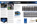
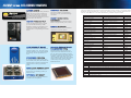
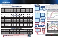
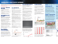
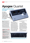
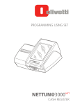
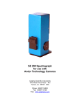
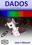
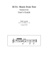
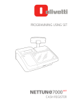
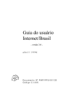
SPECTROSCOPY
CATALOG 2007
©2007 Apogee Instruments Inc.
1020 Sundown Way, Ste 150
Roseville CA 95661 USA
tel 916-218-7450
fax 916-218-7451
http://www.ccd.com
1020 Sundown Way, Ste 150
Roseville CA 95661 USA
tel 916-218-7450
fax 916-218-7451
http://www.ccd.com
HIGH PERFORMANCE
FEATURED SYSTEMS
COOLED CCD CAMERAS
A DECADE OF
IMPROVEMENTS
pogee Alta and Ascent cameras are
designed for a wide range of demanding
scientific applications.
In Ascent, we have reduced the size and
cost of our electronics and housings, while at
the same time maintaining the key features
of our popular Alta Series cameras. We’ve
added high-speed 16-bit electronics and
some new sensors with resolutions up to 16
megapixels.
The larger Alta cameras offer lower noise
and deeper cooling than the Ascent cameras.
They also support very high quantum
efficiency back-illuminated CCDs.
For both camera series, the direct USB
2.0 link between camera and computer allows
easy installation, portability and fast data
transfer rate. Ascent maintains compatibility
with our Alta ActiveX drivers, as well as
Linux and Mac OS X drivers.
DIVERSITY ADDS STRENGTH
Since 1993, Apogee Instruments has been
manufacturing cooled CCD cameras for
scientific applications. Our cameras are
now used in more than 50 countries, from
government and private research laboratories
to the best of world-class professional
observatories. Within spectroscopy, Apogee
cameras have been used for a variety of
techniques, including LIBS (laser-induced
breakdown spectroscopy), Raman, atomic,
emission, scanning and echelle spectroscopy.
They have used for water, soil, and gem
analysis; detection of anthrax; development
of methods and technologies for detection
of land mines and improvised explosive
devices (IEDs); analysis and detection of
contaminants at nuclear reactors. In other
fields, our cameras have been used to
image fingerprints without chemicals; x-ray
inspection of car parts; fluorescent imaging of
cell tissues and microtitre plates; munitions
testing; laser beam profiling; poacher
surveillance; mammography; optics testing;
discovery of thousands of astronomical
objects; and radiometry of a wide variety of
light sources.
By expanding into broad markets with
diverse demands, Apogee has had to develop
a wide variety of technologies to solve our
customers’ problems. Our spectroscopy
customers demand low noise, high sensitivity,
and high quantitative accuracy. Our life
science customers demand speed and ease of
use. Both groups are constantly pushing for
higher performance at lower prices. Ascent
and Alta cameras address these demands.
These back-illuminated CCD systems will be setting a new standard for low-cost specitroscopic systems. (Monochrome only)
Camera
Model
A1109
A1108
A1107
Hamamatsu
CCD
S10141-1109
S10141-1108
S10141-1107
Array Size
2048
506
1024
250
512
122
A1009
S10141-1009
1024
A1008
S10141-1008
A1007
A98
Total
Pixels
1036288
512000
249856
Pixel Size
(microns)
12
12
12
506
518144
12
1024
250
256000
S10141-1007
1024
122
S9840
2048
14
Array size (mm)
X
24.6
24.6
24.6
Y
Imaging Area
(mm2)
Diagonal
(mm)
6.1
3.0
1.5
149.2
73.7
36.0
25.3
24.8
24.6
12.3
6.1
74.6
13.7
12
12.3
3.0
36.9
12.6
124928
12
12.3
1.5
18.0
12.4
28672
14
28.7
0.2
5.6
28.7
HAMAMATSU: BACK-ILLUMINATED SPECTROSCOPIC FORMAT CCDs
100
INTEGRATION CD
Apogee has collected all the specification
sheets and machanical drawings for all
camera models onto an Integration Starter
Kit CD, together with software drivers and
documentation.
90
80
70
60
50
40
30
20
10
0
200
220
240
260
280
300
320
340
360
380
400
420
440
460
480
500
520
540
560
580
600
620
640
660
680
700
720
740
760
780
800
820
840
860
880
900
920
940
960
980
1000
1020
1040
1060
1080
1100
A
BACK-ILLUMINATED SPECTROSCOPIC FORMAT CCDs
We continue to refine not just our electronics
and our mechanical designs, but also our
procedures, documentation, and customer
recordkeeping. It’s quite an accomplishment
to manufacture and sell thousands and
thousands of cameras, but unless they are
robust, the result is a customer service
nightmare.
In our effort to improve our process, we’ve
achieved the following benchmarks:
· FCC compliance
· CE compliance
· ROHS compliance
· ISO-9000 compliance (in process)
Absolute Quantum Efficiency (%)
SYSTEM OVERVIEW
Our most exciting new product for specitroscopy is a series of low-cost Ascent cameras using very high quantum
efficiency Hamamatsu back-illuminated CCDs
Wavelength (nm)
Ascent
Apogee Instruments Inc.
1020 Sundown Way, Ste 150
Roseville CA 95661 USA
tel 916-218-7450
fax 916-218-7451
©2007 Apogee Instruments Inc. Alta is a registered
trademark of Apogee Instruments Inc.
www.ccd.com
Apogee Instruments Inc.
Image / spectra may be acquired using
KestrelSpecTM imaging spectroscopy software
for Windows®. See pages 14-15 of this
brochure of additional detail.
www.ccd.com
ASCENT versus ALTA SERIES CAMERAS
Ascent
Apogee Instruments Inc.
LOWER COSTS
COMPACT HOUSING
Many applications require clean, quantitative
images, but do not require the ultimate in
cooling or low readout noise. The Ascent
is an ideal solution for many applications
where several thousand dollars may be more
important than a few electrons.
The Ascent’s smaller, more lightweight
housing fits in many places that the larger
Alta cannot.
HIGHER THROUGHPUT
Ascent was designed to operate at speeds
up to the maximum allowed by USB2.
Digitization speed is programmable so you
can choose your ideal trade-off between
speed and noise. All speeds digitize at a full
16 bits.
LOW READOUT NOISE
Alta’s readout electronics were designed to
minimize readout noise. The higher speed
software-selectable 12-bit mode is intended
for focussing, and not optimized for low
noise.
ADVANCED COOLING
To maximize heat dissipation, Alta’s large
inner chamber, back plate, and heatsinks are
machined from a single block of aluminum.
The four fans have four programmable
speeds.
VERY LARGE FORMAT CCDS
The Alta platform is available in several
housing sizes, accomodating CCDs up to
50mm on a side.
OPTIONAL ETHERNET
An optional ethernet 100baseT interface is
available for the Alta platform.
The primary differences between the Ascent and Alta Series cameras: Ascent is very compact with much lower costs, much faster
digitization, and programmable gain. Alta is larger, with better cooling, and lower noise electronics. See the chart below for an
overview of the differences. See camera data sheets to get details of a specific model.
Feature
Ascent
Alta
SHORT BACK FOCAL
DISTANCE
Digitization
16 bit, programmable speed
Fast 12 and slower 16 bit
Maximum throughput
Up to 20 Mpixels/sec (Note 1)
Up to 7 Mpixels/sec (Note 1)
Dual channel interline readout
Standard
N/A
All Ascent cameras have short back focal
distances of approximately 0.32” (0.8cm).
Maximum cooling
40C below ambient (Note 2)
55C below ambient (Note 2)
EMCCD SUPPORT
The Texas Instruments TC247 EMCCD is
supported in the Ascent platform.
Programmable gain
Standard
N/A
USB2 interface
Standard
Standard
Ethernet 100baseT interface
N/A
Optional
Electromechanical shutter
Optional, external (Note 4)
Standard, internal (Note 3)
Vane shutter
Standard, internal (Note 5)
N/A
Programmable fan speed
N/A
Standard
Field upgradeable firmware
Standard
Standard
Chamber window
BK7 (optional fused silica)
Fused silica
Peripheral communications
8 pin connector
Two serial COM outputs
General purpose I/O port
Standard
Standard
Programmable LEDs
Standard
Standard
Power input
6V
12V
Internal memory
32 Mbytes
32 Mbytes
Wide variety of CCDs
Yes
Yes
IMAGING FORMAT BACKILLUMINATED CCDs
External triggering
Standard
Standard
Image sequences
Standard
Standard
Hardware binning
Up to 4 x height of CCD
Up to 8 x height of CCD
Back-illuminated CCDs are much more
expensive than front illuminated CCDs, so
they are chosen when absolutely necessary
for maximum signal-to-noise under low light
conditions. Their higher dark current per
square millimeter requires the higher cooling
of larger Alta housing, with the exception
of the small spectroscopic format backilluminated CCDs.
Subarray readout
Standard
Standard
TDI readout (Note 6)
Standard
Standard
Kinetics mode
Standard
Standard
C-mount interface (Note 7)
Optional, external (Note 7)
Standard for D1 housing
Software universality
Standard
Standard
Housing size
5.7” x 3.8” x 1.3”
6” x 6” x 2.5” (Note 8)
Warranty
2 years
2 years
Warranty against condensation
Lifetime
Lifetime
Note 1
Note 2
Note 3
Note 4
Note 5
Note 6
Note 7
Note 8
Maximum speed varies from model to model.
Maximum cooling varies from model to model.
Electromechanical shutters are standard for full frame CCDs, and optional for interline CCDs.
Electromechanical shutters are optional for all models.
Vane shutters are standard for smaller full frame CCDs, optional for interline CCDs.
Interline CCDs cannot do TDI readout.
CCDs >1” video format are too large for C-mount optics (larger than a KAF-3200ME).
Some housings are larger.
ASCENT & ALTA: SHARED FEATURES
INTERNAL MEMORY
32 Mbytes of SDRAM image memory is
included in the Alta U Series and Ascent
camera heads. 24 Mbytes of image memory
is included in the Alta E Series camera
head. Local memory serves some important
functions:
First, with any network connection and
even USB2.0 connection, consistency in
download rates cannot be guaranteed. Some
manufacturers go to great lengths to attempt
to lock Windows® up during downloads to
ensure that no pattern noise results from
breaks in the digitization process, but such
a lockup is not possible with network
interfaces. The Alta and Ascent systems
buffer the image transfer to protect from
noise-producing interruptions.
Second, on heavily loaded USB2
ports, slower USB1.1 applications, loaded
networks, or slower TCP/IP transfers, the
maximum digitization rate could be limited
without a local buffer. Local image memory
allows very fast digitization of image
sequences up to the limit of the internal
camera. The maximum digitization-tomemory rates for 100baseT systems is 1.4
megapixels per second, while the maximum
digitization-to-memory rates for Alta USB
systems is 11 megapixels per second, and
Ascent is 20 megapixels/second..
There is a fundamental difference in
the way the Alta USB2 and network image
buffers function. The USB2 image buffer
is capable of transferring data to the host
while digitization of the CCD is active. As
long as the USB2 transfer speed is greater
than the digitization rate, the memory buffer
will never fill. The network memory buffer
requires the image digitization to complete
prior to transfer across the network.
HARDWARE BINNING
Every Alta and Ascent camera supports
hardware binning up to 8 in the horizontal
direction and up to the height of the CCD in
the vertical direction. Binning can be used
to increase frame rate, dynamic range, or
apparent sensitivity by collecting more light
into a superpixel. See additional detail under
CCD University on our website.
www.ccd.com
ASCENT & ALTA: SPECIAL MODES OF OPERATION
PROGRAMMABLE LEDs
EXTERNAL TRIGGERING
Two LEDs on the side of the cameras can
be programmed to show status of a variety
of the camera functions, such as the camera
has reached the set temperature, the shutter
is open, or the camera is waiting for an
external trigger. Alternatively, the LEDs
can be turned off if you are concerned about
stray light. The E Series cameras also have
two green LEDs that indicate status of the
network connection.
The Alta and Ascent camera systems accept
external hardware trigger signals through
their camera I/O ports for a number of
purposes. Software and hardware triggers
can be used together. For example, a software
or hardware trigger may be used to initiate a
single exposure or a sequence of exposures
of a specific duration and specific delay
between exposures. Alternatively, a software
trigger may be used to start a sequence, and
the external trigger can be used to trigger
each subsequent image in the sequence.
In addition, the external trigger can be
used to trigger row shifts for time-delayed
integration, or can be used to trigger block
shifts for kinetic imaging.
SOFTWARE
SEALED INNER CHAMBERS
MaxIm DL/CCD software is standard with
every Alta, as well as an ActiveX driver that
is universal to all Apogee Alta and Ascent
cameras, as well as legacy AP and KX
cameras. If you write custom code for an
Apogee camera, you won’t have to change
it later if you change models. Our cameras
are also supported by other programs like
CCDSoft. A Linux and Mac OS X drivers are
also available.
The sensors for Alta and Ascent cameras
are sealed into an inner chamber filled with
argon. The chamber has a lifetime guarantee
against condensation.
UPGRADEABLE FIRMWARE
The Alta and Ascent systems load all camera
operating code on camera start. These
configuration files can be updated via the web
as we add features and make improvements.
Each camera head has coded information
identifying the type of system, its
configuration, and type of CCD used, as well
as the firmware revision in use. This allows
automatic configuration of the camera in the
field and better customer support from our
offices.
PROGRESSIVE SCAN
(CONTINUOUS IMAGING)
Interline transfer CCDs first shift charge
from the photodiode in each pixel to the
masked storage diode, and then march the
charge through the storage diodes to the serial
register. Acquisition of a new image in the
photodiodes during readout of the previous
image is called “progressive scan.” Alta and
Ascent cameras both support progressive
scan with interline CCDs.
TIME-DELAYED INTEGRATION
KINETICS MODE
IMAGE SEQUENCES
More formally known in astronomy as
time-delay integration (TDI), this technique
is a powerful tool for applications requring
the scan of an area larger than the CCD’s
field of view. The image is clocked down
the CCD in syncronization with the object’s
movement. The CCD must be precisely
aligned with the movement of the scene.
The simplest way to illustrate TDI is an
astronomical application. The telescope is
kept stationary, and the CCD is precisely
aligned with the sky. As the Earth rotates
and the sky drifts, the image on the CCD is
precisely clocked to continue building the
image. When the image reaches the last row,
it is read to the host computer and added to a
continuous strip of sky.
The TDI capability utilizes a 25 MHz
time base (Ascents use a 48 MHz time base)
and local memory to achieve consistent
high resolution performance. TDI mode
allows the user to adjust the row shift rate.
Timing may be adjusted in 5.12 microsecond
increments to a maximum of 336
milliseconds per row shift. The minimum
TDI shift time is the digitization time for
one row. TDI cannot be done with cameras
using interline CCDs, such as the U2000 and
U4000.
Kinetics Mode assumes that the user has
optically masked off all but the top most
section of the CCD. This exposed section is
illuminated, shifted by x rows, then exposed
again until the user has exposed the entire
surface of the CCD with y image slices.
Image sequences of up to 65535 images
can be acquired and transferred to camera /
computer memory automatically. A delay
may be programmed between images from
327 microseconds to 21.43 seconds.(This
does not mean you can acquire images every
327 microseconds; it means you can program
a delay of 327 microseconds between the
end of a readout and the start of the next
exposure.)
TWO-YEAR WARRANTY
All Apogee cameras have a standard two-year
warranty and a lifetime guarantee against
condensation in the camera.
The image in the exposed area is shifted to
the masked area per software command, preset shift frequency, or external trigger. The
number of rows per section is predetermined
and constant.
FACE PLATE ADAPTERS
Flange adapters allow you to attach anything
from an SLR camera lens to a large
instrument pack to your Apogee camera. We
have sizes to fit all Alta and Ascent cameras.
These units are machined precisely for
accurate concentricity.
www.ccd.com
Application-Driven Sequencing:
This is the most common form of image
sequencing. The application merely takes a
specified number of successive images. This
type of sequencing is suitable when the time
between image acquisitions is not short and
where slight differences in timing from image
to image are not important.
Precision back to back sequencing
Alta and Ascent incorporate a firmware
controlled back to back image sequencing
mode suitable for image-image intervals from
327uS to a maximum of 21.43 seconds in
327uS intervals. This provides for precision
spacing of images in a sequence where
windows applications cannot respond.
When the number of desired exposures has
been reached, or the CCD has been filled
(whichever comes first), the entire array is
read out and digitized. If you want to use the
entire CCD including the exposed area, then
the light source needs to be shuttered after
the final exposure (externally, electronically,
or electromechanically). or using an
SUBARRAY READOUT
Alta and Ascent cameras support readout
of an arbitrary sub-section of the array in
order to speed up frame rate. Reading half
the array, for example, does not increase
the frame rate by two because of overhead
required in discarding unwanted pixels.
The Ascent and Alta platforms allow for
three types of image sequencing:
Fast back to back sequencing (Ratio
Imaging - Interlines only)
This is a special form of precision back to
back sequencing designed for a fixed <1
microsecond spacing between a pair of
interline CCD exposures. The caveat with
this mode is that the exposure times for each
image must be greater than the readout time
for the image. For example, if using the
A2000, the readout time for a full frame is
about 0.2 seconds so your exposure would
need to be in excess of 0.2 seconds.
ALTA SERIES CAMERAS: 0VERVIEW
ADVANCED COOLING
DUAL DIGITIZATION
OPTIONAL ETHERNET
SHUTTERS
COMPACT DESIGN
The Apogee cooling system has long been
one of the most advanced in the industry.
The Alta control system has been expanded
to 12 bits, allowing a temperature control
range of 213K to 313K (-60 to +40 C)
with 0.024 degree resolution. Sensors
have been added to monitor the heat sink
temperature. A power indicator has been
added to give the user an idea of how much
drive is being given to the CCD cooler. The
automatic back-off function is now handled
by the firmware and driver. If the system
cannot reach the desired temperature, the
system automatically backs off to a point
where regulation can be maintained, 2
degrees above the maximum temperature
reached. The new set point is given to the
user. Cooling deltas of 40-60C (depending
on sensor area) are typical with simple air
cooling.
Apogee now offers liquid recirculation
backs for Alta cameras. For customers
desiring greater temperature performance
where the camera housing will not go below
the dew point, specifying liquid recirculation
will assure a lower dark count than is
possible with forced air cooling.
With our fast USB2 systems, we offer dual
digitization: high precision, low noise 16 bit
performance as well as high speed 12 bit for
focussing and other high frame rate needs.
Digitization depth is selectable image by
image in software
The Alta E Series cameras first read the entire
image into the camera head memory, and
then transfer the image to the host computer
at a maximum of 200 kpixels/second. An
Alta U47 camera with 1 megapixel reads
the entire image to the computer in about
1.5 seconds. An E47 reads the image to the
camera memory in 1.5 seconds, but then
requires an additional 5 seconds to transfer
the image to the host computer.
Apogee Instruments uses the finest shutters
available for our cameras from Vincent and
Melles Griot. These shutters have been
carefully integrated into our camera heads
with minimum impact on back focal distance
and camera size. These shutters have a huge
advantage of simple rotating blade shutters
in terms of light blockage and minimum
exposure time.
The Alta systems are designed to be very
compact. At 6”x6” and only 2.2” thick with
no external electronics, the Alta system packs
a lot of power into a small package. The Alta
systems are more than a kilogram lighter than
than their predecessor.
Alta cameras with small format CCDs
have a 0.69” (17.5 mm) C-mount back focal
distance for direct interface to microscopes
and C-mount lenses. Medium format sensors
use the D2 housing with 2” thread. Large
format sensors use the D7 housing with
a 2.5” thread. Back focal distance for the
D2 and D7 housing is approximately 1.04”
(26.4 mm). All cameras have a bolt circle
with metric threads for adaptation to a wide
variety of flanges.
PROGRAMMABLE FANS
Some customers require a complete absence
of vibration during an exposure. The Alta
systems have been designed for complete
control of the cooling fans. The fans may be
turned off, or run at a much slower speed to
maintain adequate cooling with no vibration.
For applications where vibration is not an
issue, the fan speed may be maximized for
greatest cooling. The fans used in the Alta
system were selected for minimum
vibration.
www.ccd.com
MGF2 COATED
FUSED SILICA OPTICS
UNIQUE MAC ADDRESS
Professional grade details like magnesiumflouride coated fused silica windows. Apogee
also offers custom windows, including wedge
windows and customer supplied optics.
SINGLE 12V POWER
SUPPLY
Alta camera systems include a 12V
international power supply (100V-240V
input), but can be operated from a clean 12V
source.
The Alta E Series cameras each have a unique
MAC address so they can be plugged directly
into the internet for remote operation. We
provide MaxIm software for remote control
of the camera. They cannot be controlled
through your browser.
Because the camera has slave serial, I2C,
and auxiliary filter wheel support, an entire
setup can be controlled from behind a single
camera interface. For WAN or WWW
connections, a full TCP/IP protocol gives safe
data transfers at slower speeds.
A special bi-directional digital interface
with 6 I/O lines can also be used to interface
to other system components. High level
shutter signals, as well as digital strobes and
triggers, are available.
LIQUID CIRCULATION
CABLE LENGTH
Ethernet cabling can go to 100m. USB2
cables are limited to 5m between hubs, with
up to 5 hubs, for a total of 30m. However,
there are USB1 and USB2 extenders
available for operation up to 10 km. The
USB1 extenders slow the transfer to a
maximum of 500 kpixels per seoond, but
this rate is still a far higher throughput than
the E Series systems. USB2 extenders are
available using Cat5 cable or fiber optic
cable.
Specifications subject to change without notice.
Apogee offers Alta and Ascent liquid
recirculation backs for customers wanting
to remove heat dissipation from the area of
the camera; wanting to house the camera
inside an enclosure; or wanting supplemental
cooling. The limitation: the temperature of
the recirculating liquid must not go below the
dew point.
OPTIONAL LOW PROFILE
HOUSINGS
Lower profile housings are available for all
Alta models to achieve <0.5” (<12.7mm)
back focal distances without internal shutters.
TWO SERIAL COM PORTS & GENERAL I/O PORT
Our general purpose I/O port can tell you
when the shutter is open, or can be used for
a wide variety of external trigger inputs,
including line-by-line control of TDI shifts.
Our two serial COM ports can control peripherals like filter wheels through the camera’s
control cable (USB2 or ethernet).
Alta cameras use three shutter types,
depending on the aperture. Apogee shutters
use lower voltage coils then those listed
as standard by the shutter manufacturers,
roughly 1/2 of the standard voltage
requirement. The lower voltages extend the
lifetimes of the shutters.
D1 housing, small format sensors:
Vincent Uniblitz 25mm Shutter
D2 housing, medium format sensors:
Melles Griot 43mm Shutter
D7 housing, large format sensors:
Melles Griot 63.5mm Shutter
Full frame CCDs typically require an
electromechanical shutter unless the light
source is gated in some other way. Otherwise
light falling on the sensor during the readout
process corrupts the image. Interline
CCDs shift the charge from the photodiode
section of each pixel to the masked storage
diode. For low light applications, the mask
is sufficiently opaque to prevent smearing.
However, in high light applications, interline
CCDs require electromechanical shutters to
prevent smearing during readout.
Specifications subject to change without notice.
www.ccd.com
ASCENT SERIES CAMERAS: 0VERVIEW
PROGRAMMABLE
DIGITIZATION
Unlike previous generations of Apogee
cameras with fixed digitization rates for
each bit depth, the Ascent cameras feature
programmable readout rates using 16-bit
digitization. You can choose the best tradeoff between noise and readout speed imageby-image. Some CCDs, like the interline
transfers, can read two channels at up to 10
MHz each, for a total throughput of over 20
megapixels per second. Other CCDs, like the
full frame Kodaks, typically have a maximum
useful throughput rate of about 7 to 10 MHz.
See individual data sheets for specifics
regarding each camera system.
PROGRAMMABLE GAIN
AND OFFSET
All Ascent models feature programmable
gain and bias offset programmable in the
analog-to-digital converter.
EMCCD SUPPORT
The EMCCD is unique among CCDs. It has
a special charge multiplication circuit that
intensifies charge on-ccd before readout.
Gains of 1 to 2000 are possible on-ccd using
this technology, resulting in detection of
extremely low light levels. With a gain of
1, the ccd behaves much like a normal CCD
with a maximum well depth of 28Ke- and
a typical noise of 20e-. With higher gains,
ccd output noise approaches 1e- with a
severe reduction in usable well depth. The
A247 uses an interline frame transfer CCD,
eliminating the need for a mechanical shutter
and reducing smear.
COMPACT DESIGN
The Ascent systems are extremely
lightweight (0.6 kg) and compact. At 5.7”
x 3.2” (14.5 x 8.1 cm) and only 1.2” (3 cm)
thick with no external electronics, the Ascent
is a marvel of compact electronics. The
standard back focal distance for all models is
about 0.32” (0.8 cm).
OPTIONAL LIQUID
CIRCULATION
CCD SELECTION
C
CDs come in many shapes and sizes, as
well as several different architectures.
Some architectures were developed
specifically to address the needs of extremely
low light applications like spectroscopy and
astronomy (back-illuminated CCDs). Other
technologies can be adapted to spectroscopy
with excellent results, but a bit more patience
and diligence may be necessary (interline
transfer CCDs). Here are some ideas to keep
in mind:
QUANTUM EFFICIENCY
Higher sensitivity = higher quantum
efficiency = shorter exposures to get the
same results. The peak value of a quantum
effiiciency curve does not tell the full story of
a CCD’s sensitivity. The area under the curve
gives the true comparison of a CCD’s relative
sensitivity. Twice the area under the curve =
half the time making the exposure. Or, use
the same exposure time, but get twice the
signal. Apogee supports back-illuminated,
front-illuminated, and interline transfer
devices. Back-illuminated CCDs have the
highest overall sensitivity. However, they are
subject to etaloning (aka “fringing”) in the
near-infrared. Front-illuminated CCDs are
much less expensive than back-illuminated
CCDs.
UV & NIR WAVELENGTHS
ANTI-REFLECTIVE COATED
BK7 OPTICS
The standard chamber window for the Ascent
system is low cost BK7. An optional fused
silica window is also available for applications requiring higher throughput in the
ultraviolet.
VANE SHUTTERS
Ascent cameras with full frame CCDs
have internal shutters intended to prevent
smearing during readout for low light
applications. The same professional-grade
electromechanical shutters available as
standard and internal in the Alta cameras are
also available as housed external options with
the Ascent cameras.
www.ccd.com
Apogee offers optional Ascent liquid
recirculation back as well as temperatureregulated liquid recirculators for customers
wanting to remove heat dissipation from
the area of the camera; wanting to house
the camera inside an enclosure; or wanting
supplemental cooling. The limitation: the
temperature of the recirculating liquid must
not go below the dew point.
SINGLE 6V POWER SUPPLY
Ascent camera systems include a 6V
international power supply (100V-240V
input), but can be operated from a clean 6V
source.
Specifications subject to change without notice.
Between 200-300 nm: Hamamatsu and E2V
Back-illuminated UV enhanced CCDs;
E2V open electrode CCDs (U30 only); TI
EMCCD (EM247 only).
Between 300-400 nm: most Kodak CCDs
have zero QE at 300 nm, increasing linearly
to >40% at 400 nm.
Near Infrared: Back-illuminated CCDs have
the highest QE, but they are also subject
to fringing (also known as “etaloning”)
in the near-infrared (simply put, the light
is reflected inside the CCD itself). Some
companies have developed proprietary
versions of CCDs that minimize, though not
eliminate, the effect.
PIXEL SIZE
The smaller the pixel, the lower the signal
that can be stored in the pixel (“full well
capacity”). If the noise per pixel is the same
for two cameras, lower full well means lower
signal-to-noise, or compromised image
quality.
CCD SELECTION
DYNAMIC RANGE
E2V CCDs: AIMO & NIMO
INTERLINE TRANSFER CCDs
Interline transfer CCDs have, at most, a
full well capacity of about 50K electrons. If
the electronics limits the read noise to 8-10
electrons, this is a dynamic range of 50K/10
= 5000:1, or about 12.3 bits. Most argue for
oversampling by an extra bit, or some argue
even two. However, a 16-bit analog-todigital (AtoD) converter does not upgrade a
12 bit imager into a 16 bit imager. A Kodak
KAF-1001E (Alta U6 camera), using the low
noise (aka high gain) output amplifier, can be
operated at 6 electrons noise with a full well
of 200K electrons, or a dynamic range of
more than 30K:1, about 15 bits.
E2V’s AIMO (Advanced I Metal Oxide, aka
MPP) CCDs have hundreds of times less
dark current than non-IMO (NIMO) CCDs.
Some variations of their CCDs, such as deep
depletion devices with high QE in the near
IR, are only available as NIMO devices.
Interline transfer CCDs, up to the scale of
35mm film, have inherent anti-blooming,
but less dynamic range and lower quantum
efficiency than Kodak’s other frontilluminated offerings. Interlines also have
high dark current in the storage diodes, as
well as some leakage through the storage
diode masks. Mass markets for interline
CCDs mean much lower prices per pixel,
and a great entry point into professional level
imaging.
Because interline CCDs shutter the
exposure by shifting the charge from the
photodiode section of the pixel to the storage
diode of the pixel, exposure times can be as
short as a few microseconds. Time between
exposures is determined by the time required
to read out the entire CCD, which varies from
camera to camera.
Interline transfer CCDs cannot do timedelayed integration (also known as “drift
scan” mode) because charge is not transferred
from photodiode to photodiode, but rather
into the masked storage diode.
CCD GRADES
Each manufacturer’s specification sheet for
an imager defines the cosmetic grades for
that specific imager. Different manufacturers
use different procedures; a grade 1 of Imager
A may allow column defects, but a grade 2
(lower grade) of Imager B may not. Kodak
usually grades their CCDs at about 25°C,
and most of their defects disappear in cooled
cameras when the images are flat-fielded. In
most cases, you cannot see the difference
between the grades. Other companies,
such as E2V, grade their CCDs at low
temperatures, so their defects are less likely
to disappear when the CCD is cooled.
Defects on CCDs do not grow over time,
nor do lower grade CCDs wear out faster.
Most lower grade Kodak CCDs no longer
allow column defects. These lower priced
CCDs are excellent bargains.
You may get an unwanted surprise if you
do not check the data sheets for each CCD
carefully before purchasing a system. Some
large format CCDs allow several column
defects in the “standard grade” CCD,
DARK CURRENT
Thermally generated signal, or dark current,
is not noise. The shot noise component of the
dark current is one element of noise, which
is the square root of the dark current. You
can correct for the dark current itself if you
can measure it, which requires the camera’s
cooling to be programmable and stable. The
deeper the cooling, the less correction you’re
going to have to do.
KODAK BLUE PLUS CCDs
CCDs create charge due to the photoelectric
effect. In order to create an image rather
than random electricity, the charge must be
held where it was created. “Traditional”
CCDs using from one to four polysilicon
gates carry a voltage that traps the charge
until transferred. Polysilicon has limited
transmissivity. Indium tin oxide (ITO) gates
have higher transmissivity, but lower charge
transfer efficiency. Kodak’s combination
of one polysilicon gate and one ITO gate
is marketed as Blue Plus (because of the
increase in blue sensitivity). The overall
sensitivity of Blue Plus CCDs is much higher
than multi-phase front-illuminated CCDs
using only polysilicon gates. However,
when researching point sources of light, it is
good to keep in mind that there is a marked
increase in quantum effiiency on the ITO side
of each pixel. (See MICROLENSES below).
MICROLENSED CCDs
Many CCDs now use microlenses over
each pixel. In the case of interline transfer
CCDs, the microlenses focus the light onto
the photodiode. In the case of Blue Plus
CCDs (see above), the microlenses focus
the light onto the ITO gate side of the pixel.
Microlenses greatly improve overall quantum
efficiency, but introduce some angular
dependency. Fill factor is normally less than
100%. See data sheets for individual CCDs
for details.
www.ccd.com
ANTI-BLOOMING
Anti-blooming (AB) bleeds off excess charge
from individual pixels so that it does not spill
over into its neighbors and cause a white
stripe down the column. For applications like
astrophotography, AB preserves the aesthetics
of the image. For photometric applications,
AB can be used if exposure times are
carefully controlled to avoid excess charge.
The disadvantages of AB: normally it lowers
full well capacity and quantum efficiency.
SPECSMANSHIP
CCD manufacturers as well as camera
manufacturers both describe their products
in terms of typical performance, and in some
cases, specify worst acceptable performance.
A CCD data sheet may, for example, say
“typical 15 electrons noise” and “maximum
20 electrons noise” (under very specific
and perhaps irrelevant conditions). As a
result, camera manufacturers using such a
CCD must also use “typical performance”,
or sort CCDs at a potentially large increase
in cost. The difference between typical and
guaranteed is sometimes large, such as a
factor of two in dark current.
CCD SELECTION
CCD SIZES
BACK ILLUMINATED
177
27.4
FRONT ILLUMINATED
FRONT-ILLUMINATED CCDs
3058
3058
9351364
12
36.7
36.7
1346.6
51.9
M
A8300
KAF-8300
3448
2574
8875152
5.4
18.6
13.9
259
23.2
M,C
U9, A9
U10
U32, A32
KAF-6303E
3072
2048
6291456
9
27.6
18.4
509.6
33.2
M
TH7899*
2048
2048
4194304
14
28.7
28.7
822.1
40.6
M
KAF-3200
2184
1472
3214848
6.8
14.9
10.0
148.7
17.9
M
KAF-1603ME
1536
1024
1572864
9
13.8
9.2
127.4
16.6
M
U13
KAF-1301E
1280
1024
1310720
16
20.5
16.4
335.5
26.2
M
U6
KAF-1001E
1024
1024
1048576
24
24.6
24.6
604.0
34.8
M
KAF-0402ME
768
512
393216
9
6.9
4.6
31.9
8.3
M
KAF-0261E
512
512
262144
20
10.2
10.2
104.9
14.5
M
U2, A2
U1, A1
U260, A260
A340
KAI-0340
Array Size
4872
3248
4008
2672
2048
2048
1600
1200
648
484
CAMERA DATA SHEETS
Total
Pixel Size Array size (mm) Imaging Area Diagonal Mono=M
Pixels
(microns)
X
Y
(mm2)
(mm)
Color=C
15824256
7.4
36
24
866.5
43.3
M,C
10709376
9
36
24
867.5
43.3
M,C
4194304
7.4
15.2
15.2
229.7
21.4
M,C
1920000
7.4
11.8
8.9
105.1
14.8
M,C
313632
7.4
4.8
3.6
17.2
A complete set of camera data sheets as well as
mechanical drawings are on our Integration Starter Kit
CD, or at www.ccd.com
5.99
Wavelength
UV Enhanced
OE
Broadband
FRONT-ILLUMINATED CCDs
A105
A8300
100
90
80
U2
E2
A2
U32
E32
A32
INTERLINE TRANSFER CCDs
Kodak CCD
KAI-16000
KAI-11002
KAI-4021
KAI-2021
Midband BI
U260
E260
A260
U1
E1
A1
INTERLINES
*The U10 uses an E2V (formerly Atmel, formerly Thomson) TH7899 CCD.
Camera
Model*
A16000
A11000
U4000, A4000
U2000, A2000
0
U9
E9
A9
96
0
KAF-09000
10
A16000
A11000
U4000
E4000
70
60
50
40
30
20
U2000
E2000
EMCCD
EM247
10
0
A340
M,C
Wavelength (nm)
www.ccd.com
Back-illuminated
Kodak Blue Plus
Microlensed
KAI-11002
10
00
U9000
U10
E10
1000
C
92
0
32
88
0
475
960
17.8
84
0
26.6
920
6.8
80
0
10275584
880
2624
76
0
3916
840
KAF-10500CE
20
72
0
A105
30
U13
E13
800
Array Size
4096
4096
4096
4096
40
68
0
Kodak CCD*
KAF-16801E
KAF-16803
Total
Pixel Size Array size (mm) Imaging Area Diagonal Mono=M
Pixels
(microns)
X
Y
(mm2)
(mm)
Color=C
16777216
9
36.9
36.9
1359.0
52.1
M
16777216
9
36.9
36.9
1359.0
52.1
M
50
20
0
Camera
Model
U16
U16M
60
64
0
M,C
760
8.24
60
0
32.6
720
5.0
56
0
6.6
680
10
52
0
326368
640
496
48
0
658
70
U6
E6
600
TI TC247
80
560
EM247
U16
U16M
U9000
90
44
0
EMCCDs
EM
CCDs
100
40
0
6.7
Apogee also offers a variety of spectroscopic
format back-illuminateed CCDs.
E2V UV-sensitive CCDs
E2V: BACK-ILLUMINATED
& OPEN ELECTRODE CCDs
36
0
26.6
39.1
18.8
17.4
520
26
764
177
151
32
0
262144
U77
E77
480
256
Y
27.6
13.3
12.3
U47
E47
Diagonal
(mm)
28
0
1024
X
27.6
13.3
12.3
Imaging Area
(mm2)
440
CCD30-11
Array size (mm)
400
Array Size
2048
2048
1024
1024
512
512
Pixel Size
(microns)
13.5
13
24
Absolute QE
U30
E2V CCD
CCD42-40
CCD47-10
CCD77-00
Total
Pixels
4194304
1048576
262144
U30 / E30
U42
E42
The QE curves below give general representations of the relative differences between the
various types of CCDs. For additional detail, please see the data sheets for each camera
model at www.ccd.com. QE of back-illuminated CCDs depends on the coating (midband,
broadband, UV-enhanced). There are also variations in front-illuminated CCDs: all
polysilicon gates; Blue Plus (polysilicon and indium tin oxide gates); microlenses; antiblooming. See individual camera data sheets for details regarding each sensor.
24
0
BACK-ILLUMINATED CCDs
For nearly 30 years, back-illuminated CCDs have represented the ultimate in high performance imaging. The highest sensitivity
available means shorter exposures and better signal-to-noise. (Monochrome only)
Camera
Model
U42
U47
U77
QUANTUM EFFICIENCY
Absolute QE (%)
Alta Series cameras with a USB2 interface use a U prefix, for example, U42. Alta Series cameras with an ethernet interface use an E
prefix, for example, E42. All Alta models are available with either interface except the U16, U16M, and U9000 (USB2 only). Ascent
models use an A prefix, except the EM247. In addition to the following CCDs, the Ascent supports a variety of spectroscopic format
back-illuminated CCDs listed on a following page.
KESTRELSPECTM SPECTROSCOPY SOFTWARE
Alta and Ascent cameras are supported by KestrelSpecTM real-time Windows ® imaging
spectroscopy software from Catalina Scientific (KestrelSpec content ©1996-2007 Catalina
Scientific Instruments LLC).
Download a demo version of KestrelSpec Lite from www.catalinasci.com, along with the
user manual and a tutorial.
LITE & FULL VERSIONS:
FEATURES
• Completely integrated camera and
spectrograph control for supported
instruments.
• Calibrate single-order spectrographs using
least squares, spline, or polynomial fit
• Calibrate scanning spectrographs using 1point KestrelCal
• Calibrate multiple-order echelle
spectrographs using 2-point KestrelCal
TRUE SPECTRUM FLAT
FIELDINGTM
KestrelSpec provides true spectrum flat
fielding, using one or more reference light
sources to correct for absorbing medium
between the source and spectrograph,
spectrograph optics, grating efficiency,
camera quantum efficiency and interference
effects (etaloning) when using backilluminated CCDs.
• Simple, accurate, relative intensity
correction by using an incandescent reference
source with a known temperature
• Full, automatic intensity correction using
a reference spectrum from any continuous
spectrum light source with a known spectrum
• Powerful, broadband, intensity correction
by joining spectra of multiple reference
sources
• For echelle spectrographs, automatic
rescaling of the flat field curve to accomodate
different spectral resolutions.
DATA ACQUISITION
• Select arbitrary areas from the CCD for
spectral curves.
• Up to 10,000 curve memories in RAM for
spectral plots with up to 65,000 points per
curve.
• Select CCD pixel-grouping (binning)
modes, kinetics mode, external triggering
• Fully adjustable temperature control on all
CCD cameras.
• Maximum frames/second depends on
binning mode, subarray size, readout rate and
number of curves per image.
• 16 bit-per-pixel images. 32 bit-per-pixel
spectral curves. Curve data can be either
long integer or floating point.
• Programmable sequences with control
of number of exposures, adjustable delays
between exposures, number of scans, and
summation of multiple image exposures.
• Real-time, dark background and flat-field
image buffers.
• Automatic background subtraction and flatfield correction.
• Automatic flip image horizontal when
image is reversed.
• Automatic save of images and curves to
disk.
• Conversion of data to log or absorbance
scales.
• Calibrate spectral data in wavelength (nm)
or Raman shift (cm-1).
• Autoscan and autocalibrate spectra with
fully integrated spectrograph control option
for supported spectrographs.
FULL VERSION:
ADDED FEATURES
• KestrelTemp automated temperature
measurement from blackbody spectra.
• KestrelScriptTM capabilty enables other
Windows programs, like LabView® from
National Instruments, to send commands
to and receive data from KestrelSpec using
Dynamic Data Exchange (DDE).
• Element Identification process to identify
the elements contained in a sample spectrum.
Ideal for LIBS (laser-induced breakdown
spectroscopy).
Channel profile graph (bottom) shows a slice
at a constant wavelength along the Z axis
(time) of 3D spectral curves.
DATA ANALYSIS & DISPLAY
• Image display: 256 gray levels positive/
negative, 23-level pseudocolor with
quantitative, color coded legend.
• 2-D and 3-D curve overlays or vertically
stacked curves.
• Channel profile Y(t) plot (Z axis slice).
• Line, bar, cityscape and scatter plot styles.
• Graphic spectrum catalog with “thumbnail”
plots.
• Baseline Correction: click on spectrum
to select points for nth order polynomial
regression curve used in baseline flattening.
• Real-time spectral peak finder determines
the centroid and width.
• "Join Curves" joins multiple spectra with
overlapping wavelength coverage into a
single linearized spectrum for scanning
spectrographs.
• Curve Math: add, subtract, multiply or
divide curves with other spectral curves, or
apply a constant value to curves.
• Smooth curves according to an adjustable
threshold.
• "Renormalize X axis" accurately linearizes
spectra for all types of spectrographs.
• "Laser beam profiler" display with XY
profile graphs.
OTHER FEATURES
• Import/export spectral data in ASCII
text format. Exported curve data can then
be imported into a spreadsheet program
or an analysis program like GRAMS or
MATLAB®.
• Import/export image data in binary integer,
ASCII text, Windows bitmap or grayscale
TIF formats. “Swap byte” capability for
importing 16-bit image data created on a
Macintosh.
• Print plots and images in grayscale or color.
• Copy plots or images to the clipboard for
pasting into other applications.
• Save spectral and image data in a
proprietary, KestrelSpec format so files can
be saved on disk and then opened later for
analysis.
ADDED FEATURES IN FULL VERSION
KESTRELSCRIPTTM
KESTRELTEMPTM
In the full version, the scripting system
for KestrelSpec software lets you send
commands to KestrelSpec from another
program, including National Instruments’
LabView®. KestrelScript commands
include standard menu items as well as
other instructions which transfer spectral
data from KestrelSpec to the controlling
program, adjust the wavelength calibration
of KestrelSpec, etc. KestrelScript effectively
lets you use KestrelSpec as a very high-level
driver for the CCD.
In the full version of the KestrelSpec
software, there is an option to acquire and
display spectral curves in “Temperature
Mode”. KestrelTempTM is a method of
calculating the unknown temperature of
spectral data once a temperature reference
curve, with a known temperature, has been
defined. This known temperature reference
curve and any unknown sample curve are
then transformed by a proprietary algorithm
to produce a linear function of relative
intensity versus frequency (Omega). The
temperature of the unknown source can
then be calculated from the slope of this
relationship between relative intensity and
frequency. The software calculates a least
squares fit to the function and determines the
temperature of the unknown source including
a 1 sigma error coefficient. The accuracy of
the temperature calculation can be optimized
by adjusting the spectral range over which the
least squares fit is operating.
ELEMENT IDENTIFICATION
In the full version of the KestrelSpec
software, there is an option to identify
common elements in spectral curves, which
is ideal for LIBS (laser-induced breakdown
spectroscopy). The Element Identification
option on the main Process menu allows the
user to search for elements in any spectral
curve that is calibrated in nm units. Use
either NIST tables or user-defined tables of
reference wavelengths for each element.
KestrelSpec has versatile graphing and data
analysis options. The Control Palette (above)
yields quick access to numeric keypad, peak
finder, zooming, panning, XY cursor and
other tools.
Above: Echelle spectrograph image from
deuterium-tungsten source (UV at top).
Below: linearized spectrum created from
the image, generated by linking the multiple
orders together. Echelle spectrographs offer
much higher sampling resolution by taking
advantage of the area of imaging CCDs.
Spectrum Catalog displays up to 25
“thumbnails” in one window to give an
overview of current spectral curves in
memory. Cut and paste the thumbnails or
mark them for deletion. Select a thumbnail
plot to be expanded to a full window.
Raman image and spectrum
“Laser beam profiler” display for X and Y
cross section plots.
THANKS (A PARTIAL LIST OF APOGEE INSTRUMENTS CUSTOMERS)
Apogee Instruments would like to express our gratitude to the thousands of customers from around the world that
have brought so much to our lives since 1994.
Aerospace Corporation • Air Force Research Laboratory • Aloe Ridge Observatory (South Africa) • American Red Cross • Anglo-Australian
Observatory • Ankara University Observatory (Turkey) • Apache Point Observatory • Appalachian State University • Argonne National Laboratory
• Astronomical Institute of the Czech Republic • Astronomical Observatory Belgrade (Yugoslavia) • Astrophysical Observatory, College of
Staten Island • Auckland Observatory (New Zealand) • Bacs-Kiskun Observatory (Hungary) • Baja Astronomical Observatory (Hungary) • Ball
Aerospace • Bang & Olufsen (Denmark) • Baton Rouge Observatory • Baylor University • Bechtel • Beijing Observatory (China) • Big Bear Solar
Observatory • Boeing • Bohyunsan Optical Astronomy Observatory (Korea) • Boston University • Brigham Young University • California Institute
of Technology • Centre National de la Recherche Scientifique (France) • Centro de Investigaciones en Optica (México) • Chiang Mai University
(Thailand) • Chiba University (Japan) • Chinese University of Hong Kong • Clemson University • Colorado School of Mines • Columbia University
• Complejo Astronómico El Leoncito (Argentina) • Copenhagen University (Denmark) • Cork Institute of Technology (Ireland) • Corning • Crimean
Astrophysical Observatory (Ukraine) • Czech Technical University (Czech Republic) • Daimler Benz Aerospace (Germany) • Department of National
Defence, Canada • DLR e.V. (Germany) • Dublin Institute for Advanced Studies, Dunsink Observatory (Ireland) • Dworp Observatory (Belgium)
• Eastman Kodak • Ege University (Turkey) • Florida Institute of Technology / SARA • Ford Motor • Fox Chase Cancer Center • Fudan University
(China) • Fuji • Fujitsu • Gemini Telescope Project • Gøteburg University (Sweden) • Harvard-Smithsonian Center for Astrophysics • Harvard
College Observatory • Heron Cove Observatory • Hida Observatory (Japan) • High Energy Accelerator Research Organization (Japan) • High
Frequency Active Auroral Research Program (HAARP) • Hiroshima University (Japan) • Hitachi • Hong Kong University of Science & Technology
• Imation • Indian Institute of Astrophysics • Industrial Technology Research Institute (ITRI) (Taiwan) • Institute for Astronomy, Hawaii • Institute of
Astronomy (Switzerland) • Institute of Astronomy and Astrophysics (Taiwan) • Institute of Atomic and Molecular Sciences (Taiwan) • Institute for
Quantum Physics (Switzerland) • Instituto de Astrofisica de Andalucia (Spain) • Instituto de Astrofisica de Canarias (Spain) • Inst. Estudis Espacials
de Catalunya (Spain) • International Science & Technology Centre (Russia) • IVIC-CBB (Venezuela) • J.Paul Getty Museum • Jagellonian University
(Poland) • Japan Atomic Energy Agency • Jet Propulsion Laboratory • Johns Hopkins University • Kimberly-Clark • Kim-Hae Observatory (Korea)
• Kitt Peak National Observatory • Konkoly Observatory (Hungary) • Korea Astronomical Observatory • Korea Research Institute of Standards
and Science • Kwasan Observatory (Japan) • Kyoto University (Japan) • Lancaster University (UK) • Landessternwarte Heidelberg-Königstuhl
(Germany) • Las Cumbres Observatory • Lawrence Berkeley National Laboratory • Lawrence Livermore National Laboratory • Lick Observatory
• Liverpool John Moores University (UK) • Lockheed Martin • London Health Sciences Centre (Canada) • Los Alamos National Laboratory •
Lucent Technologies • Lund Observatory (Sweden) • Mauna Loa Observatory • Max Planck Institute (Germany) • McGill University (Canada) •
MIT • MIT Lincoln Laboratory • Mt. Cuba Astronomical Observatory • Mt. Diablo Observatory • Mt. Stromlo Observatory (Australia) • Mt. Wilson
Observatory • Multiple Mirror Telescope • Nagoya University (Japan) • NASA Goddard SFC • NASA Marshall SFC • NASA Langley Research
Center • National Astronomical Observatory (Japan) • National Central University (Taiwan) • National Cheng Kung University (Taiwan) • National
Health Research (Taiwan) • National Institute for Advanced Interdisciplinary Research (Japan) • National Institute of Advanced Industrial Science
and Technology (Japan) • National Institute for Materials Science (Japan) • National Institute of Standards & Technology • National Oceanographic
and Atmospheric Administration • National Solar Observatory • National Sun Yat-Sen University (Taiwan) • National Tsing Hua University (Taiwan)
• National University of Ireland • Naval Post Graduate School • Naval Research Laboratory • Northwestern University • NTT (Japan) • Oak Ridge
National Laboratory • Observatoire Côte d’Azur (France) • Observatoire de Geneve (Switzerland) • Observatorio “Carl Sagan” (Mexico) • Occidental
College • Okayama Astrophysical Observatory (Japan) • Oxford University (UK) • Osaka University (Japan) • Oulu University (Finland) • Panasonic
• Physical Research Laboratory (India) • Police Scientific Development Branch, Scotland Yard (UK) • Pomona College • Portland State University
• Princeton University • Purdue University • Purple Mountain Observatory (China) • Queens University (Canada) • Rice University • Riken (Japan)
• Rockefeller University • Royal Military College of Canada • Royal Observatory (Edinburgh, Scotland) • Russian Academy of Sciences • Sandia
National Laboratory • Science and Technology Centre of Ukraine • Shamakhy Astrophysical Observatory (Azerbaijan) • Smithsonian Observatory •
South African Astronomical Observatory • Stanford University • State Universities of Arizona, Georgia, Iowa, Louisiana, Michigan, Montana, New
York (SUNY), North Carolina, Ohio, Pennsylvania, Tennessee, and Texas • Stanford University • Starkenburg Observatory (Germany) • Sternberg
Astronomical Observatory (Russia) • Steward Observatory • Stockholm Observatory (Sweden) • Subaru Telescope • Swarthmore College • Tel
Aviv University • Temple End Observatory (UK) • Tenagra Observatories • Texas A&M University • Texas Tech University • Tokyo Institute of
Technology • Tokyo University • Toshiba • Tuorla Observatory (Finland) • Turku Centre for Biotechnology (Finland) • Universidad de Buenos Aires
(Argentina) • Universidad de Sonora (Mexico) • Universidade Federal da Paraiba (Brazil) • Universität Hamburg (Germany) • Universität Innsbrück
(Austria) • University College Dublin (Ireland) • University of Amsterdam (Netherlands) • University of the Andes (Venezuela) • University of
Auckland (New Zealand) • University of Bern (Switzerland) • University of Birmingham (UK) • University of Bologna (Italy) • Universidad de
Entre Rios (Argentina) • University of Chicago • Universities of Alaska, Arizona, Arkansas, California, Colorado, Georgia, Hawaii, Idaho, Illinois,
Indiana, Iowa, Maryland, Massachusetts, Michigan, Nevada, North Carolina, Pennsylvania, Texas, Virginia, Washington, Wisconsin, and Wyoming •
University of the Free State (South Africa) • University of Hong Kong • University of Latvia • University of Leicester (UK) • University of Ljubljana
(Slovenia) • University of London Observatory (UK) • University of Manchester Jodrell Bank Observatory (UK) • University of Manitoba (Canada) •
University of Melbourne (Australia) • University of Miami • University of Munich (Germany) • University of Notre Dame • University of Sao Paulo
(Brazil) • University of St. Andrews (Scotland) • University of Toronto (Canada) • University of the West Indies • University of Zurich (Switzerland)
• US Naval Observatory • Valencia University Observatory (Spain) • Vanderbilt University • Vatican Observatory • Virginia Military Institute •
Visnjan Observatory (Croatia) • Warsaw University Observatory (Poland) • Waseda University (Japan) • Wayne State University • Weizmann Institute
(Israel) • Westinghouse • Wise Observatory (Israel) • Yale University • Yerkes Observatory (University of Chicago) • Yonsei University (Korea)
1020 Sundown Way, Ste 150
Roseville CA 95661 USA
tel 916-218-7450
fax 916-218-7451
http://www.ccd.com
©2007 Apogee Instruments Inc.