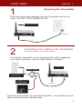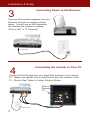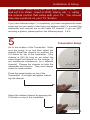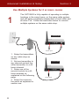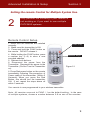
1
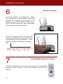
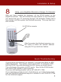
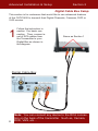
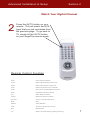
Patent Pending
CATV2400 Wireless Cable
TV System
Set-Up
and
User Manual
Patent Pending (Utility and Design)
CONTENTS:
Page:
1. Powering the Transmitter
2. Powering the Receiver
3. Transmitter Setup
4. Receiver Setup / Installing the Remote Batteries
5. Setting up the Remote
6. Connecting You Digital Box
7. Watching Your Digital Channels (Or DVD, etc...)
8. Using Multiple CATV2400 systems
9. Remote Control Setup fro Multiple Systems
FEATURES:
1. Watch Cable TV on a remote TV, Computer or other CRT device in
any room or even outside your home within 300’
2. Transmits CATV (Cable TV) signals or signals from other video
devices such as Cameras, DVD Player, VCD, VCR, Satellite Receiver.
3. Transmit range is about 250’ indoors (Estimate)
4. Built-in 433MHz and IR remote gives commands over the transmitter
and receiver separately.
5. Encoded 433MHz remote avoids interference caused by other 433
products.
6. Memory functions enables the devices to remain on the last used TV
channel.
NOTE: Monitor should have RCA input (Composite)
7. FCC/CE Approval
SPECIFICATIONS:
Transmitter:
Frequency:
Transmitting Power
No. of Channels
Video In/Out
Video System
Remote
Power Consumption
Operating Temperature
Weight
Dimensions (WHD)
RECEIVER:
Frequency
No. of Channels
Video Out
Remote
Video Output Level
Power Consumption
Operating Temperature
Weight
Dimensions (WHD)
2400~2483MHz
0dBm(FCC) 10dBm(CE)
4 (2410,2430,2450,2470)
Cable, Air TV, Composite
NTSC or PAL or SECAM
433MHz
DC9V, 500mA
-10C~50C
260g
152x125x35 (mm)
2400~2483MHz
4 (2410,2430,2450,2470)
Composite
433MHz
1 Vp-p
DC9V, 500mA
-10C~50C
140g
117x85x42 (mm)
START HERE
Section 1
Powering the Transmitter
1
Plug one of the power adapters into your Transmitter and into an
outlet. DO NOT TURN POWER ON YET
Attach Antenna
9V DC Input
2
Connecting Your Cable to the Transmitter
The cable provided by your service provider
Connect the transmitter to your incoming cable outlet supplied by
your cable tv provider. (Use the Cable Splitter if needed)
Transmitter
Cable Splitter
Incoming Cable from
Cable Provider
To Main TV Set
or Digital Box
9V DC Input
Press the power button on top of the transmitter. You should see a red
light on the transmitter will iulluminate.
1
Installation & Setup
Connecting Power to the Receiver
3
Plug one of the power adapters into your
Receiver and into an outlet as shown
below. You will see an LED indicating
the channel the receiver is utilizing.
(This is NOT a TV Channel)
9V DC Input
Connecting the receiver to Your TV
4
Connect the RCA plugs from your AngelTrax receiver to your remote
TV. Please use special care to match colors from the receiver to the
TV. (Red to Red, Yellow to Yellow, White to White)
Rear of
Remote
TV
9V DC Input
2
Installation & Setup
(STOP) Now, Make sure you turn your remote TV on
and set it to Video , Input or DVD, Game, etc....) using
the remote control that came with your TV. You should
now see a picture on your TV Screen.
If you have followed steps 1-4 completely, you have completed the basic
setup and you are ready to start enjoying wireless cable TV provided the
transmitter and receiver are on the same RF channel. If you are NOT
receiving a picture, please perform the following steps, 5 & 6.
5
Transmitter Setup
Go to the location of the Transmitter. Make
sure the power is on and then select the
desired AngelTrax channel by pushing the
CH button on top of the transmitter. (Any
channel is OK) As long as we select the
same AngelTrax channel on the receiver. (If
you experience interference, try a different
channel) Change the channel on both the
transmitter and receiver. They must always
match to communicate.
Press the power button on top of the
Transmitter. A red light will appear indicating the channel.
Select the desired channel by pressing the
CH button on top of the transmitter.
3
Installation & Setup
6
Receiver Setup
Go to the location of the Receiver. Make
sure the power is on and then select the
desired RF channel by pushing the CH
button on top of the receiver. (Any channel is OK) As long as you select the same
RF channel on the transmitter.
Press the channel button on top of the
receiver selecting the same RF channel selected on the transmitter. A red
light will appear indicating the channel.
Make sure your TV is ON and it is
set to Video, Input 1, AV1, etc...
7
CATV2400 Remote Control
Install the batteries in the the rear pocket of the AngelTrax
remote control correctly. Place the battery cover on the
remote.
4
Installation & Setup
8
Using your Angeltrax Remote to Change TV Channels
After you have installed the batteries, hit the SCAN button on the
AngelTrax remote. This will activate the scan feature on the transmitter.
You should see your TV scanning through 125 channels. Please wait a
few minutes until the system has finished scanning. This may take several minutes.
Hit SCAN on remote
STD
HRC
IRC
After the system has finished scanning, you
are ready to select the desired channel
using the CH up and down feature.
Quick Troubleshooting
If you receive only channel 5 or channel 6, you are most likely on HRC
cable frequencies. The system comes set to STD. To change to HRC,
hold the FUNC key while pressing the HRC button as shown above.
This will change the system to HRC mode. Now hit the SCAN button
and wait for the system to stop scanning.
If you are still haveing trouble, call us at 1-800-673-1788.
If you experience a high amount of interference, go to http://www.angeltrax.com/catv2400/interference.asp for a solution or call 1-800-673-1788
for live technical support.
5
Advanced Installation & Setup
Section 2
Digital Cable Box Setup
This section is for customers that would like to use advanced features
of the CATV2400 to transmit their Digital Channels, Cameras, DVD or
VHS movies.
1
Follow the instruction in
section 1 for basic connection. Then, connect a
set of RCA cables from
the Transmitter to your
Digital Box as shown in
the diagram
Same as Section 1
Digital Cable Box
6
Note: You can connect any device to the RCA connectors on the back of the transmitter. Such as, Camera,
DVD, VHS, etc...
Advanced Installation & Setup
Section 2
Watch Your Digital Channel
2
Press the AV/TV button on your
remote. This will select the RCA
input that you just connected from
the previous page. To go back to
TV, simply hit the AV/TV button
on your AngelTrax remote again.
Remote Control Function
Power
Power On/Off the transmitter
TX. CH
Switch 2.4GHz transmitting channels of Tx
RX. CH
Switch 2.4GHz receiving channels of Rx
TV/AV
Switches TV and Video input on transmitter
FUNC*
Sets up an new encoded address of the remote
SCAN
Automatically scans all TV channels
CH + -
Adds or deletes TV channels
CH+/CH-
Switches TV channels in sequence
VOL+/VOL-
Turns up or down the output volume
MUTE
Silent
DISPLAY
Shows OSD status
JUMP
Turns back to the previous TV channel
MTS
Bilingual system
0~9
Selects a TV channel directly by pressing number keys
7
Advanced Installation & Setup
Section 3
Use Multiple Systems for 2 or more rooms
1
The CATV2400 is fully capable of operating in multiple
locations in the same home, on the same cable system
and still being completely independent of each other and
all other TVs. Follow the instruction below to connect
multiple systems on the same cable drop.
Transmitter
9V DC Input
1. Setup the transmitters
on any cable drop as
shown.
2. Set one transmitter to
any channel and set the
other transmitter to a different channel.
3. Setup one of the
remote controls to a different address as
explained on the following
page.
4. Setup the receivers
the same as explained in
section one.
8
Transmitter
9V DC Input
Advanced Installation & Setup
Section 3
Setting the remote Control for Multiple System Use.
2
Only perform the following if your remote is
not working or if you want to use multiple
CATV2400 systems.
Remote Control Setup
1. Make sure the batteries are installed
correctly.
2. Make sure the transmitter is ON.
3. Press and hold the FUNC button on
the remote. DO NOT release it.
4. While holding the FUNC button, press
a number key (1~9) to store a new
encoded address.
5. Release both buttons.
6. Disconnect the power from the
Transmitter. Reconnect the power to the
Transmitter (Do Not Turn the Transmitter
on)
6. Press Red power button on the remote
immediately following Re-connection of
Power cable of the transmitter. (Within 5
Seconds) When you press the Red
Button, this should turn the transmitter
ON. If not, repeat the steps above all
within 5 seconds.
FUNC Key
Number Keys
Figure 2.1
Your remote is now programmed to your wireless transmitter.
Note: All remotes come set to FUNC / 1 as the default setting. In the case
of multiple systems, choose a number between 2-9 on one of the remotes.
9
Trouble Shooting
Please read this user manual carefully before using the Wireless CATV System. If you still have difficulties using this product, please consult the following which will help you solve the most common
problems.
No picture or sound
· Check and make sure the DC adapters are connected correctly.
· Check and make sure all cables are connected correctly (Yellow to Yellow, Red to red and White to
White)
· Make Sure the transmitter is turned on by remote or tact switch.
· Make sure the transmitter is NOT out of range. If so, the transmitter or the receiver needs to be relocated. (Always locate the Transmitter to the closest cable drop to that of the remote TV)
Interference in picture or sound
· Check if there is any interference radio frequency source near your place such as microwave oven
and cordless phone. If so, call 1-800-673-1788 for assistance.
· Check if there is any other 2.4GHz wireless product working near your place such as WLAN,
Bluetooth wireless products. If so, switch to a new transmission channel. If you still have interference, go to www.angeltrax.com/catv2400/troubleshooting.asp or call 1-800-673-1788
Signal loss (no response) in remote control
· Check if the batteries are well and installed correctly.
· Check if the encoded address of the transmitter and the remote is matched. (See remote Control
Setup, Section 2)
Warranty
This warranty gives you specific legal rights that vary from state to state. IVS, Inc. warrants this product to be free from
defects in material and workmanship under normal use and service for a period of one (1) year from the date of original
purchase. The terms and conditions of said warrant are as follows:
1. The date of purchase and proof of an AngelTrax Authorized Dealer must be established by original sales receipt which
must accompany the unit being returned for warranty service.
2. Item must be returned to the factory in the original carton or equivalent freight PPD. If unit is received with S/N removed
or defaced, warranty is void.
3. This warranty shall not apply to any unit that has been used for a purpose for which it was not designed or any unit that
has been altered in any way. Evidence indicating that the unit was not properly used will void warranty.
4. AngelTrax Wireless does not authorize any other persons to assume liability in connection with it’s products. This warranty is the only express warranty made by IVS, Inc. to this product. Any implied warranty or merchantability or fitness for
a particular purpose applicable to IVS, Inc. products is limited in duration to the duration of this limited warranty. Some
states or provinces do not allow the exclusion or limitation of incidental or consequential damages or limitations on how
long an implied warranty lasts. Therefore the above limitations may not apply.
5. In the unlikely event that warranty becomes necessary, contact your local AngelTrax Authorized Dealer for assistance
with the return and repair of your product. If an authorized dealer is not available, contact us at 1-800-673-1788 to obtain
an RMA# and instructions.
6. Warranty is valid in USA only
Interactive Video Solutions, Inc.
AngelTrax Wireless
9540 US Hwy 84 West
Suite 2
Newton, AL 36352
AngelTrax is registered trademark of IVS, Inc.
Copyright 2004