1
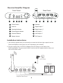
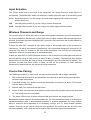
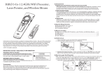
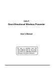
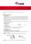
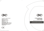
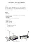
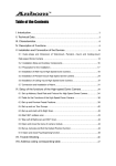
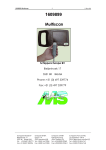
Wireless Speaker Transmitter
2.4G Digital Wireless Surround Amplifier
Userʼs Manual
Safety Warnings and Guidelines
Thank you for purchasing this Wireless Speaker Amplifier! For best results, please
thoroughly read this manual and carefully follow the instructions. Please pay extra attention
to the safety warnings to ensure that no harm comes to you or your equipment. Please
keep this manual for future reference.
• DO NOT touch the power plug or the device itself with wet hands.
• DO NOT expose this device to water or moisture. Do not place items with water or
moisture, such as a flower vase or drinking glass, on or near this device.
• DO NOT pull on the power cord to remove the plug from the outlet. Always grip the
connector head or AC adapter body when unplugging the device.
• DO NOT place the device in direct sunlight or expose it to excessive heat. Do not place
it near any heat source, such as a fireplace, stove, or radiator.
• DO NOT place any objects on top of the device. Ensure that the device is in a well
ventilated area to prevent overheating.
• DO NOT disassemble or modify the device for any reason. There are no user serviceable
parts inside. Attempting to disassemble or modify the unit will VOID THE WARRANTY!
Package Contents
Please take an inventory of the package contents to ensure you have all the items listed
below. If anything is missing or damaged, please contact Monoprice Customer Service for
a replacement.
• 1 x Wireless Audio Transmitter
• 1 x Switch Power Adaptor (5V/1A)
• 1 x 3.5mm convert RCA cable (connecting home theater DVD/Amplifier audio source)
• 1 x 3.5mm convert 3.5mm cable (connecting Laptop/PC, MP3 audio source)
• 1 x Wireless Surround Amplifier
• 1 x Switch Power Adaptor (14V/3 A)
• 1 x 3.5mm convert 3.5mm cable (for wired music transmission)
2
Transmitter Diagram
1
2
3
4
5
6
7
8
9
10
11
Front Panel
Rear Panel
12
13
1
Not utilized on PID 10601
8
Charging LED Indicator
2
Volume Up
9
Channel Down
3
Power LED Indicator
10 Antenna
4
Channel Up
11 Setup Mode Switch
5
Channel/Volume Display
12 Power Switch
6
Audio In
13 DC Power In
7
Volume Down
3
Receiver/Amplifier Diagram
Front Panel
Rear Panel
DC14V/2.5A
1
2
3
4
5
7
6
8
9
1
Power Switch
7
Antenna
2
Audio In
8
Right Output “-”
Right Output “+”
3
Overload Indicator
9
4
Power/Signal Indicator
10
Left Output “-”
5
Channel Selector
11
Left Output “+”
Master Volume
12
DC Power In
6
10
11
Installation Instructions
1. Use ordinary speaker wire (not included) to connect the left and right outputs from the
Receiver/Amplifier to the inputs of a pair of speakers (not included).
Antenna
2. Plug the output of the 14 VDC AC adapter to the DC IN port on the back of the
Receiver/Amplifier. Plug one end of the AC cord into the AC adapter and the other end
into an AC power outlet.
110V Outlet
2
Speakers
-
R OUT
SPEAKER
+
-
L OUT
+
DC5V/1A
SPEAKER
1
Amplifier Rear Panel
4
12
Antenna
110V Outlet
4
Transmitter Rear Panel
0 DB
STANDBY
20 DB
ANT
MUSIC
MIC
OFF
ON
POWER
DC 3.6V〜6V
5
Computer or other
audio source
STATUS
CH+
VOL+
VOLCHARGE CH-
AUDIO
Transmitter Front Panel
3
3. Using the 3.5mm stereo audio cable, connect one end to the Audio jack on the front of
the Transmitter and the other end into the output of your audio source (smartphone,
computer, etc.).
4. Plug the output of the 5 VDC AC adapter to the DC IN port on the back of the Transmitter.
Plug the other end into an AC power outlet.
5. Slide the power switch on the back of the Transmitter to the ON position.
6. Flip the power switch on the front of the Receiver/Amplifier to the ON position.
ALTERNATE: Note that instead of using the wireless Transmitter, you can plug your source
device directly into the Line In jack on the front of the Receiver/Amplifier.
40
60
OFF
PO W ER
LINE IN
OVERLOAD STATUS
80
20
ON
CH+
0
100
-VOLUME+
6
ALTERNATE
Amplifier Front Panel
5
Input Selection
The 3.5mm Audio jack on the front of the transmitter can accept line-level audio input or a
microphone. The MUSIC/MIC switch on the back is used to select the type of source being used.
Music: Select this option if you are using a line-level audio signal (which could be musical,
spoken word, etc.).
0dB:
Use this switch position if you are using a normal microphone.
20dB: Use this switch position if you are using a mic with a highly sensitive pickup.
Wireless Channels and Range
This system uses a 2.4GHz WiFi carrier to transmit the audio information from the transmitter to
the receiver/amplifier. Because the 2.4GHz WiFi band is rather crowded with wireless devices of
all kinds, this system provides 30 different WiFi channels, more than twice the number offered by
Wireless-N routers.
If there are other WiFi channels in use within range of this system there is the potential for
interference. To reduce this chance of interference, we recommend changing to channels 21-30
using the CH+ and CH- buttons on the front of the transmitter. The receiver will automatically
change the channel to match that of its paired transmitter.
If there are other WiFi or 2.4GHz wireless devices in use in the area, this transmitter and receiver
have an effective range in clear air of up to about 55 feet (17 meters). If there are no other 2.4GHz
transmissions in the area, the clear air range is increased to up to about 98 feet (30 meters). The
presence of walls and floors within a home, as well as the presence of other electrical
transmissions and emissions, will reduce the range somewhat.
One-to-One Pairing
The following procedure is used to pair a single receiver/amplifier with a single transmitter.
1.
Ensure that both the receiver and transmitter are powered on and that they are well within
wireless range listed above.
2.
Press and hold the CH+ buttons on both the transmitter and receiver for about 3-5 seconds,
until the status LEDs flash.
3.
Release both CH+ buttons at the same time.
4.
Power off both the transmitter and receiver, wait for about 30 seconds, then power them both
on. The two devices are now paired.
5.
The status LEDs will be off when the transmitter and receiver are properly paired.
Because the system features 30 wireless channels, you can theoretically have up to 30 sets of
transmitter/receiver pairs in simultaneous operation. A practical application for using multiple
pairs of receivers and transmitters is to wirelessly connect your 5.1 home theater speaker
system. One set can be used to drive the front speakers, the second set can drive the rear
surround speakers, and a third set can be used to feed the audio signal to the subwoofer.
6
One-to-Multiple-Pairing
In addition to operating as multiple independent pairs, you can also configure the system to have
a single transmitter broadcasting to any number of receivers within range.
1. Ensure that the transmitter and the first receiver/amplifier are powered on.
2. Press and hold the CH+ buttons on both the transmitter and receiver for about 3-5 seconds,
until the status LEDs flash.
3. Release both CH+ buttons at the same time.
4. Power off both the transmitter and receiver, wait for about 30 seconds, then power them both
on. The two devices are now paired.
5. Power off the receiver, then power on the next receiver you want to pair to this transmitter.
6. Repeat steps 2-5 for all subsequent receivers you wish to pair with the single transmitter.
7. Power on all receivers. They should now be paired to the transmitter. The status LEDs will be
off when the receivers are properly paired to the transmitter.
This mode of operation is perfect for distributing audio to multiple rooms or zones. Note that you
can combine the use of multiple receivers with a single transmitter and the use of multiple
transmitter pairs to distribute multichannel audio (5.1, 7.1 etc.) to multiple locations.
Restoring Factory Default Settings
If you want to set the transmitter and/or receiver back to the condition it was in when you received
it, simply press and hold the CH+ button for about 20 seconds until the status LED begins to
flash. Power the device off, wait about 30 seconds, then power it on again and it will be restored
back to the default settings.
Specifications
Frequency Response . . . . . . . . . . . . . . . . . . . . 20Hz-20KHz
RF Frequency . . . . . . . . . . . . . . . . . . . . . . . . . . 2400MHz-2483MHz
Total Harmonic Distortion . . . . . . . . . . . . . . . . . 0.3%@1KHz
S/N Ratio . . . . . . . . . . . . . . . . . . . . . . . . . . . . . . 95dB
Latency . . . . . . . . . . . . . . . . . . . . . . . . . . . . . . . <0.5ms
Operating Temperature . . . . . . . . . . . . . . . . . . . -13 ~ +185°F (-25 ~ +85°C)
Audio Transmitter Power Requirements . . . . . . 3.6~6.0 VDC
Output Power of the Transmitter . . . . . . . . . . . . 20dBm
Amplifier Power Requirements . . . . . . . . . . . . . 14 VDC
Output Power of the Amplifier . . . . . . . . . . . . . . 30W+30W
7