1
UAD POWERED PLUG-INS
USER GUIDE
SOFTWARE VERSION 5.9.0
MANUAL VERSION 110429
Universal Audio, Inc.
1700 Green Hills Road
Scotts Valley, CA 95066-4926
Voice: +1-831-440-1176
Fax: +1-831-461-1550
www.uaudio.com
Customer Support (USA):
1-877-MY-UAUDIO (877-698-2834)
NOTICES
Disclaimer
This manual provides general information, preparation for use, installation and
operating instructions for the Universal Audio UAD Powered Plug-Ins. The
information contained in this manual is subject to change without notice.
Universal Audio, Inc. makes no warranties of any kind with regard to this
manual, or the product(s) it refers to, including, but not limited to, the implied
warranties of merchantability and fitness for a particular purpose.
Universal Audio, Inc. shall not be liable for errors contained herein or direct,
indirect, special, incidental, or consequential damages in connection with the
furnishing, performance, or use of this material or the product(s).
Damage Requiring Service
The unit should be serviced by qualified service personnel when:
• The AC power supply cord or the plug has been damaged;
• Objects have fallen or liquid has been spilled into the unit;
• The unit has been exposed to rain;
• The unit does not operate normally or exhibits a marked change in
performance;
• The unit has been dropped, or the enclosure damaged.
FCC Compliance
Ventilation
This equipment has been tested and found to comply with the limits for a Class
B digital device, pursuant to part 15 of the FCC Rules. These limits are designed
to provide reasonable protection against harmful interference in a residential
installation.
This equipment generates, uses and can radiate radio frequency energy and, if
not installed and used in accordance with the instructions, may cause harmful
interference to radio communications. However, there is no guarantee that
interference will not occur in a particular installation.
If this equipment does cause harmful interference to radio or television
reception, which can be determined by turning the equipment off and on, the
user is encouraged to try to correct the interference by one or more of the
following measures:
• Reorient or relocate the receiving antenna.
• Increase the separation between the equipment and receiver.
• Connect the equipment into an outlet on a circuit different from that to which
the receiver is connected.
• Consult the dealer or an experienced radio/TV technician for help.
Caution: Changes or modifications not expressly approved by Universal Audio
could void the user's authority to operate the equipment.
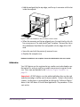
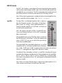
When installing the unit in a rack or any other location, be sure there is
adequate ventilation. Improper ventilation will cause overheating, and can
damage the unit.
Warranty
Important Safety Instructions
Before using this unit, be sure to carefully read the applicable items of these
operating instructions and the safety suggestions. Afterwards keep them handy
for future reference. Take special care to follow the warnings indicated on the
unit, as well as in the operating instructions.
Water and Moisture
Do not use the unit near any source of water or in excessively moist
environments.
Object and Liquid Entry
Care should be taken so that objects do not fall, and liquids are not spilled, into
the enclosure through openings.
Heat
The unit should be situated away from heat sources, or other equipment that
produces heat.
Power Sources
The unit should be connected to a power supply only of the type described in
the operating instructions, or as marked on the unit.
Power Cord Protection
AC power supply cords should be routed so that they are not likely to be walked
on or pinched by items placed upon or against them. Pay particular attention to
cords at plugs, convenience receptacles, and the point where they exit from the
unit. Never take hold of the plug or cord if your hand is wet. Always grasp the
plug body when connecting or disconnecting AC.
Cleaning
The external unit should be cleaned only with a damp cloth and mild soap if
necessary. Chemical cleaners may damage the silkscreen and/or finish.
Nonuse Periods
The AC power supply cord of the unit should be unplugged from the AC outlet
when left unused for a long period of time.
The Warranty for all Universal Audio hardware is one (1) year from date of
purchase, including parts and labor.
Service & Support
Even the best-built audio equipment in the world will sometimes fail. In those
rare instances, our goal here at UA is to get you up and running again as soon
as possible. If you are experiencing problems with your UAD product, please
visit the Universal Audio website at http://www.uaudio.com to validate
compatibility, and read the FAQs regarding UAD products. If you still require
service, contact UA Tech Support at 877-MY-UAUDIO, or visit
http://www.uaudio.com/support/contact.html to create a help ticket, and we
will help troubleshoot your system. (Canadian and overseas customers should
contact their local distributor, which can be found using the Dealer Locator at
http://www.uaudio.com.) When calling Tech Support for assistance, please
have the product serial number available, and have your unit set up in front of
you, turned on, and exhibiting the problem. This will help us diagnose and
solve any problems as quickly as possible. Thank you.
The user should not attempt to service the unit beyond that described in the
operating instructions. All other servicing should be referred to qualified service
personnel.
Universal Audio, Inc.
End User License Agreement
By installing the software, you confirm your acceptance of the Universal Audio
and third-party End User License Agreements, as well as the Universal Audio
terms of service and privacy policy, all of which can be found at:
http://www.uaudio.com/eula
This Agreement is between Universal Audio, Inc., and you. IMPORTANT PLEASE READ THIS LICENSE AGREEMENT CAREFULLY BEFORE
INSTALLING THIS SOFTWARE. By using the Universal Audio software
("Universal Audio Software"), you accept these terms. The Universal Audio
Software may be distributed with software or components from third-parties
("Third-party Software") that are subject to different terms which can be found
at: http://www.uaudio.com/eula, and also the provisions of Section 11 below.
If you do not accept these terms, do not use the software provided with this
installation. Instead, return the Universal Audio Software or Third-Party
Software to the reseller for a refund or credit. If you cannot obtain a refund from
the reseller, or if you purchased your software license directly from Universal
Audio, Inc. ("Universal Audio"), contact Universal Audio for information
about Universal Audio's refund policies. Please visit the Web sites listed at the
end of this document for contact details.
This Universal Audio End-User License Agreement ("Agreement") is a legal
agreement between you (either an individual or a single entity), as an end-user,
and Universal Audio for the Universal Audio Software accompanying this
Agreement, which includes computer software, updates and any bug fixes
subsequently delivered and associated media, printed materials and "online" or
electronic documentation, The Universal Audio Software is licensed, not sold,
by Universal Audio to the original end user for use only on the terms set forth
here.
1. Limited Use License. Universal Audio, as Licensor, grants you, as Licensee, a
non-exclusive license to use the Software with a single computer unit at a single
location.
2. Title. The Software is owned by Universal Audio or its suppliers and is
protected by copyright laws and international treaty provisions, as well as other
intellectual property laws and treaties. Universal Audio retains title to and
ownership of the Software and all copies thereof in any form. Universal Audio
retains all rights in the Software not specifically granted to the Licensee. This
Agreement only gives you certain rights to use the Software and related
documentation, which may be revoked if you do not follow these terms.
3. Limited Rights to Install and Use the Software
(i) Permitted use and restrictions. You may install the Software into the memory
of a single computer, but may not electronically transfer the Software to
someone else's computer or operate it in a time-sharing or service-bureau
operation. Additionally, you may only use the Software on a computer that
contains a maximum of eight (8) UAD cards, specifically four UAD-1 cards and
four UAD-2 cards. The sole exception is that, if you are a licensee of the UAD2 Solo/Laptop card or UAD-2 Satellite, you may link the card to an existing
computer previously registered.
(ii) Reverse engineering and copying limitations. You may make one copy of the
Software for backup purposes only (and replacement backup copies in the event
of loss of or damage to a backup copy), provided you include all copyright
notices contained on the original media on the backup copy. You may not
modify, translate, adapt, reverse engineer, decompile, create other works from,
or disassemble the Software or any portions thereof (except and to the extent
that applicable law expressly permits reverse engineering, decompilation or
disassembly). Similarly, you may not copy, modify, adapt, transfer, or create
other works based upon the printed materials and "online" or electronic
documentation accompanying or published for use with the Software (the
"Documentation").
(iii) Technical limitations. The Software may include technological measures,
whether in the Software or in bundled hardware or both, that are designed to
prevent or detect unlicensed use of the Software. Circumvention of these
technological measures is prohibited, except and only to the extent that
applicable law expressly permits, despite this limitation. Any attempt to
circumvent technical limitations may render the Software or certain features
unusable or unstable, and may prevent you from updating or upgrading the
Software.
(iv) No reconfiguration. The Software is licensed for installation and use only
in the manner it was provided to you, as configured by an automated
installation program provided with the Software, or as described in Universal
Audio's documentation. You may not separate the components contained in
the Software or otherwise reconfigure the Software to circumvent technical
limitations on the use of the Software or to otherwise exceed the scope of your
license.
4. Export, Renting and Transfer Restrictions. You may not export, convey, rent,
sublicense, or otherwise distribute the Software or any rights therein to any
person or entity. You may, however, transfer the Software license but only
under the following limited terms and conditions.
(i) Eligible transferees: You may transfer the license to a transferee:
(a) for whom you have provided registration details (your name, hardware
ID(s), user e-mail ID, buyer's name and buyer's e-mail address) to Universal
Audio at [email protected] in advance of such transfer; and (b) who has agreed
to be bound by the terms of this license by registering with Universal Audio at
my.uaudio.com and confirming such agreement during installation of the
Software. Any such permitted transferee may not subsequently transfer this
license and the limited 90 day warranty set forth in Section 5 shall expire upon
such permitted transfer.
(ii) Eligible products: the Software may only be transferred in connection with
up to four (4) UAD-1 cards and four (4) UAD-2 cards per user account. Special
exceptions may arise where the use of more than eight (8) UAD cards is
required. These cases are generally related to areas of education and multi-room
facilities, and require advanced approval if requesting to sell or transfer over the
allotted (8) cards per account. If you have questions or are seeking an exception,
please contact customer support.
5. Limited Warranty. Universal Audio grants solely to you a limited warranty
for a period of ninety (90) days from the original purchase date that the media
on which the Software is distributed shall be substantially free from material
defects. Your exclusive remedy, at Universal Audio's option, is to return and
have replaced the inaccurate media containing the Software programs or receive
a refund of the price paid within the warranty period. UNIVERSAL AUDIO
DOES NOT WARRANT THAT THE SOFTWARE WILL MEET YOUR
REQUIREMENTS OR THAT ITS OPERATION WILL BE
UNINTERRUPTED OR ERROR-FREE. EXCEPT AS SPECIFIED
HEREIN, UNIVERSAL AUDIO MAKES NO WARRANTIES OR
REPRESENTATIONS, EXPRESS OR IMPLIED, REGARDING THE
SOFTWARE, DOCUMENTATION, OR MEDIA, AND HEREBY
EXPRESSLY DISCLAIMS THE WARRANTIES OF
MERCHANTABILITY, FITNESS FOR A PARTICULAR PURPOSE, AND
NON-INFRINGEMENT OF THIRD PARTY RIGHTS.
FURTHERMORE, UNIVERSAL AUDIO DOES NOT WARRANT OR
MAKE ANY REPRESENTATIONS REGARDING THE USE OR THE
RESULTS OF THE USE OF THE SOFTWARE OR DOCUMENTATION
IN TERMS OF THEIR CORRECTNESS, ACCURACY, RELIABILITY,
OR OTHERWISE. NO ORAL OR WRITTEN INFORMATION OR
ADVICE GIVEN BY UNIVERSAL AUDIO OR A UNIVERSAL AUDIOAUTHORIZED REPRESENTATIVE SHALL CREATE A WARRANTY
OR IN ANY WAY INCREASE THE SCOPE OF THIS WARRANTY.
EXCEPT AS SPECIFIED HEREIN, SHOULD THE SOFTWARE PROVE
DEFECTIVE, YOU (AND NOT UNIVERSAL AUDIO OR A UNIVERSAL
AUDIO-AUTHORIZED REPRESENTATIVE) ASSUME THE ENTIRE
COST OF ALL NECESSARY SERVICING, REPAIR, OR CORRECTION.
SOME JURISDICTIONS DO NOT ALLOW THE EXCLUSION OF
IMPLIED WARRANTIES, SO THE ABOVE EXCLUSION MAY NOT
APPLY TO YOU.
6. Limitation of Liability. UNIVERSAL AUDIO SHALL HAVE NO
LIABILITY TO YOU OR ANY THIRD PARTY, WHETHER IN
CONTRACT, TORT, NEGLIGENCE OR PRODUCTS LIABILITY, FOR
ANY CLAIM, LOSS, OR DAMAGE, INCLUDING BUT NOT LIMITED
TO LOST PROFITS, LOSS OF USE, BUSINESS INTERRUPTION, LOST
DATA, OR LOST FILES, OR FOR ANY INDIRECT, SPECIAL,
INCIDENTAL OR CONSEQUENTIAL DAMAGES OF ANY KIND OR
NATURE WHATSOEVER ARISING OUT OF OR IN CONNECTION
WITH THE USE OF OR INABILITY TO USE THE SOFTWARE OR
DOCUMENTATION, OR THE PERFORMANCE OR OPERATION OF
THE SOFTWARE, EVEN IF Universal Audio HAS BEEN ADVISED OF
THE POSSIBILITY OF SUCH DAMAGES. SOME STATES DO NOT
ALLOW THE EXCLUSION OR LIMITATION OF INCIDENTAL OR
CONSEQUENTIAL DAMAGES, SO THE ABOVE EXCLUSION OR
LIMITATION MAY NOT APPLY TO YOU. IN NO EVENT SHALL
UNIVERSAL AUDIO'S TOTAL LIABILITY TO YOU FOR ALL
DAMAGES, LOSSES, AND CAUSES OF ACTION WHETHER IN
CONTRACT, TORT (INCLUDING NEGLIGENCE) OR OTHERWISE
EXCEED THE AMOUNT PAID BY YOU FOR THE SOFTWARE.
(EULA continued next page)
7. Termination. To the extent permitted by law, and without prejudice to any
other rights Universal Audio may have, Universal Audio may terminate your
license if you materially breach these terms and conditions. Upon termination
by Universal Audio, you will return to Universal Audio, at your expense, the
Software, including documentation, and any copies thereof.
8. United States Government Rights. The Software and Documentation are
provided with RESTRICTED RIGHTS. Use, duplication, or disclosure by the
Government is subject to restrictions as set forth in subparagraph (c)(1)(ii) of
the Rights in Technical Data and Computer Software clause at DFARS
252.227-7013 or subparagraphs (c)(1) and (2) of the Commercial Computer
Software-Restricted Rights at 48 CFR 52.227-19, as applicable. Manufacturer
is Universal Audio, Inc., 1700 Green Hills Road, Scotts Valley, CA, 950664926 USA.
9. Export restrictions. The Software is subject to United States export laws and
regulations. If you are subject to U.S. laws, you must comply with these laws,
which include restrictions on destinations, end users and end use. For further
information, please see http://www.bis.doc.gov.
10. Consent to Use Data. Universal Audio may collect and use technical
information about the Software and hardware devices you use in connection
with the Software in a manner that does not personally identify you. Universal
Audio may use this information to improve our products or to provide
customized services or technologies. Universal Audio may also disclose this
information to third parties so that they may improve the way their products or
services interact with the Software.
11. Third Party Software; Third Party Information. Your installation and use
of Third-Party Software is subject to different terms, which can be found on the
media on which the software is provided, or at: http://www.uaudio.com/eula.
Nothing in this agreement limits rights granted to you by third parties, which
may include rights under free software or open source software license.
Additionally, Universal Audio may include information about third party
products and services, including links to Web sites run by others. Universal
Audio is not responsible for, and does not endorse or sponsor, this third-party
information.
12. Miscellaneous. This Agreement shall be governed by and construed in
accordance with the laws of the United States and the State of California, as
applied to agreements entered into and to be performed entirely within
California between California residents. If for any reason a court of competent
jurisdiction finds any provision of this License or portion thereof to be
unenforceable, that provision of the License shall be enforced to the maximum
extent permissible so as to effect the intent of the parties, and the remainder of
this License shall continue in full force and effect. This Agreement constitutes
the entire agreement between the parties with respect to the use of the Software
and Documentation, and supersedes all prior or contemporaneous
understandings or agreements, written or oral, regarding such subject matter.
No amendment to or modification of this License will be binding unless in
writing and signed by a duly authorized representative of Universal Audio.
Should you have any questions concerning this Agreement, please contact
Universal Audio at 1700 Green Hills Road, Scotts Valley, CA, 95066-4926
USA, +1-831-440-1176 voice, +1-831-461-1550 fax, www.uaudio.com web.
Copyright
©2011 Universal Audio, Inc. All rights reserved.
This manual and any associated software, artwork, product designs, and design
concepts are subject to copyright protection. No part of this document may be
reproduced, in any form, without prior written permission of Universal Audio,
Inc. Your rights to the Software are governed by the accompanying End-User
license agreement.
Trademarks
Universal Audio, the Universal Audio "diamond" logo, UAD, UAD Series,
UAD-1, UAD-2, UAD-2 SOLO, UAD-2 DUO, UAD-2 QUAD, "Powered
Plug-Ins", 1176LN, 1176SE, Teletronix, LA-2A, LA-3A, LA-610, LA610MkII, 2-1176, 2-610, 6176, 710 Twin-Finity, 2192, Cambridge EQ,
DreamVerb, Plate 140, Precision Limiter, RealVerb Pro, Precision Buss
Compressor, Precision De-Esser, Precision Maximizer, Satellite DUO, Satellite
QUAD, and "Analog Ears | Digital Minds," are trademarks or registered
trademarks of Universal Audio, Inc. Other company and product names
mentioned herein are trademarks of their respective owners.
EULA v110412
TABLE OF CONTENTS
Chapter 1. Introduction . . . . . . . . . . . . . . . . . . . . . . . . . . . . . . . . . . . . . . . . .
17
Welcome!. . . . . . . . . . . . . . . . . . . . . . . . . . . . . . . . . . . . . . . . . . . . . . . . . . . . . . . . . . . . . . . . . . . . 17
Features . . . . . . . . . . . . . . . . . . . . . . . . . . . . . . . . . . . . . . . . . . . . . . . . . . . . . . . . . . . . . . . . . . . . . 19
The UAD System . . . . . . . . . . . . . . . . . . . . . . . . . . . . . . . . . . . . . . . . . . . . . . . . . . . . . . . . . . . . . . 20
Package Contents . . . . . . . . . . . . . . . . . . . . . . . . . . . . . . . . . . . . . . . . . . . . . . . . . . . . . . . . . . . . . 20
Documentation Overview . . . . . . . . . . . . . . . . . . . . . . . . . . . . . . . . . . . . . . . . . . . . . . . . . . . . . . . 20
Online Documentation . . . . . . . . . . . . . . . . . . . . . . . . . . . . . . . . . . . . . . . . . . . . . . . . . . . . . . . . . 22
Customer Support . . . . . . . . . . . . . . . . . . . . . . . . . . . . . . . . . . . . . . . . . . . . . . . . . . . . . . . . . . . . . 22
Chapter 2. UAD Installation . . . . . . . . . . . . . . . . . . . . . . . . . . . . . . . . . . . . . .
24
Overview . . . . . . . . . . . . . . . . . . . . . . . . . . . . . . . . . . . . . . . . . . . . . . . . . . . . . . . . . . . . . . . . . . . . 24
Install Videos . . . . . . . . . . . . . . . . . . . . . . . . . . . . . . . . . . . . . . . . . . . . . . . . . . . . . . . . . . . . . . . . . 24
System Requirements . . . . . . . . . . . . . . . . . . . . . . . . . . . . . . . . . . . . . . . . . . . . . . . . . . . . . . . . . . . 25
Supported Hosts . . . . . . . . . . . . . . . . . . . . . . . . . . . . . . . . . . . . . . . . . . . . . . . . . . . . . . . . . . . . . . 25
Latest Information & Software Updates . . . . . . . . . . . . . . . . . . . . . . . . . . . . . . . . . . . . . . . . . . . . 26
UAD Software Installation . . . . . . . . . . . . . . . . . . . . . . . . . . . . . . . . . . . . . . . . . . . . . . . . . . . . . . . 27
Install Software First . . . . . . . . . . . . . . . . . . . . . . . . . . . . . . . . . . . . . . . . . . . . . . . . . . . . . . . . . . . 27
UAD Hardware Installation. . . . . . . . . . . . . . . . . . . . . . . . . . . . . . . . . . . . . . . . . . . . . . . . . . . . . . 29
Authorization . . . . . . . . . . . . . . . . . . . . . . . . . . . . . . . . . . . . . . . . . . . . . . . . . . . . . . . . . . . . . . . . . 31
Authorize Plug-Ins Procedure . . . . . . . . . . . . . . . . . . . . . . . . . . . . . . . . . . . . . . . . . . . . . . . . . . . . 32
Offline Authorization . . . . . . . . . . . . . . . . . . . . . . . . . . . . . . . . . . . . . . . . . . . . . . . . . . . . . . . . . . 33
Using Unlicensed Plug-Ins (Demo Mode) . . . . . . . . . . . . . . . . . . . . . . . . . . . . . . . . . . . . . . . . . . . 34
Verifying Installation . . . . . . . . . . . . . . . . . . . . . . . . . . . . . . . . . . . . . . . . . . . . . . . . . . . . . . . . . . . 34
Learn More . . . . . . . . . . . . . . . . . . . . . . . . . . . . . . . . . . . . . . . . . . . . . . . . . . . . . . . . . . . . . . . . . . 36
Software Removal . . . . . . . . . . . . . . . . . . . . . . . . . . . . . . . . . . . . . . . . . . . . . . . . . . . . . . . . . . . . . 36
Chapter 3. UAD System Overview . . . . . . . . . . . . . . . . . . . . . . . . . . . . . . . . .
37
The UAD Environment . . . . . . . . . . . . . . . . . . . . . . . . . . . . . . . . . . . . . . . . . . . . . . . . . . . . . . . . . . 37
The UAD Hardware. . . . . . . . . . . . . . . . . . . . . . . . . . . . . . . . . . . . . . . . . . . . . . . . . . . . . . . . . . . . 37
The UAD Software . . . . . . . . . . . . . . . . . . . . . . . . . . . . . . . . . . . . . . . . . . . . . . . . . . . . . . . . . . . . . 41
The DAW Environment . . . . . . . . . . . . . . . . . . . . . . . . . . . . . . . . . . . . . . . . . . . . . . . . . . . . . . . . . 43
My.uaudio.com . . . . . . . . . . . . . . . . . . . . . . . . . . . . . . . . . . . . . . . . . . . . . . . . . . . . . . . . . . . . . . . 45
Authorization . . . . . . . . . . . . . . . . . . . . . . . . . . . . . . . . . . . . . . . . . . . . . . . . . . . . . . . . . . . . . . . . . 45
Chapter 4. My.uaudio.com . . . . . . . . . . . . . . . . . . . . . . . . . . . . . . . . . . . . . . .
46
Optional Plug-Ins . . . . . . . . . . . . . . . . . . . . . . . . . . . . . . . . . . . . . . . . . . . . . . . . . . . . . . . . . . . . . . 46
Authorization Overview . . . . . . . . . . . . . . . . . . . . . . . . . . . . . . . . . . . . . . . . . . . . . . . . . . . . . . . . 47
Authorization Notes . . . . . . . . . . . . . . . . . . . . . . . . . . . . . . . . . . . . . . . . . . . . . . . . . . . . . . . . . . . 49
Demo Mode . . . . . . . . . . . . . . . . . . . . . . . . . . . . . . . . . . . . . . . . . . . . . . . . . . . . . . . . . . . . . . . . . . 50
UA Online Store . . . . . . . . . . . . . . . . . . . . . . . . . . . . . . . . . . . . . . . . . . . . . . . . . . . . . . . . . . . . . . 51
UAD Powered Plug-Ins Manual
-5-
Table of Contents
TABLE OF CONTENTS
Buying Plug-Ins . . . . . . . . . . . . . . . . . . . . . . . . . . . . . . . . . . . . . . . . . . . . . . . . . . . . . . . . . . . . . . . 52
Transferring UAD devices and licenses . . . . . . . . . . . . . . . . . . . . . . . . . . . . . . . . . . . . . . . . . . . . 53
Chapter 5. Using Multiple UAD Devices. . . . . . . . . . . . . . . . . . . . . . . . . . . . . .
54
Overview . . . . . . . . . . . . . . . . . . . . . . . . . . . . . . . . . . . . . . . . . . . . . . . . . . . . . . . . . . . . . . . . . . . . 54
Plug-In License Policy . . . . . . . . . . . . . . . . . . . . . . . . . . . . . . . . . . . . . . . . . . . . . . . . . . . . . . . . . . 54
UAD Link Licensing . . . . . . . . . . . . . . . . . . . . . . . . . . . . . . . . . . . . . . . . . . . . . . . . . . . . . . . . . . . . 55
Authorizing Multiple Devices . . . . . . . . . . . . . . . . . . . . . . . . . . . . . . . . . . . . . . . . . . . . . . . . . . . . 56
UAD-1 with UAD-2 . . . . . . . . . . . . . . . . . . . . . . . . . . . . . . . . . . . . . . . . . . . . . . . . . . . . . . . . . . . . 56
Power Requirement . . . . . . . . . . . . . . . . . . . . . . . . . . . . . . . . . . . . . . . . . . . . . . . . . . . . . . . . . . . . 56
Multidevice DSP Loading . . . . . . . . . . . . . . . . . . . . . . . . . . . . . . . . . . . . . . . . . . . . . . . . . . . . . . . 57
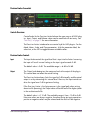
Device Info Display . . . . . . . . . . . . . . . . . . . . . . . . . . . . . . . . . . . . . . . . . . . . . . . . . . . . . . . . . . . . 58
Disabling Devices . . . . . . . . . . . . . . . . . . . . . . . . . . . . . . . . . . . . . . . . . . . . . . . . . . . . . . . . . . . . . 58
Host CPU . . . . . . . . . . . . . . . . . . . . . . . . . . . . . . . . . . . . . . . . . . . . . . . . . . . . . . . . . . . . . . . . . . . . 58
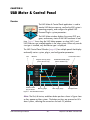
Chapter 6. UAD Meter & Control Panel . . . . . . . . . . . . . . . . . . . . . . . . . . . . . .
60
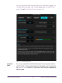
Overview . . . . . . . . . . . . . . . . . . . . . . . . . . . . . . . . . . . . . . . . . . . . . . . . . . . . . . . . . . . . . . . . . . . . 60
Launching the UAD Meter & Control Panel Application . . . . . . . . . . . . . . . . . . . . . . . . . . . . . . . 61
Using the UAD Meter . . . . . . . . . . . . . . . . . . . . . . . . . . . . . . . . . . . . . . . . . . . . . . . . . . . . . . . . . . 61
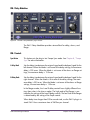
UAD Meter Elements . . . . . . . . . . . . . . . . . . . . . . . . . . . . . . . . . . . . . . . . . . . . . . . . . . . . . . . . . . . 62
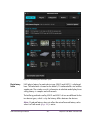
UAD Control Panel . . . . . . . . . . . . . . . . . . . . . . . . . . . . . . . . . . . . . . . . . . . . . . . . . . . . . . . . . . . . 63
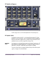
System Information Panel . . . . . . . . . . . . . . . . . . . . . . . . . . . . . . . . . . . . . . . . . . . . . . . . . . . . . . . 64
Plug-Ins Panel . . . . . . . . . . . . . . . . . . . . . . . . . . . . . . . . . . . . . . . . . . . . . . . . . . . . . . . . . . . . . . . . 67
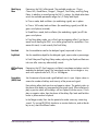
Configuration Panel . . . . . . . . . . . . . . . . . . . . . . . . . . . . . . . . . . . . . . . . . . . . . . . . . . . . . . . . . . . 70
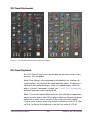
FireWire Panel . . . . . . . . . . . . . . . . . . . . . . . . . . . . . . . . . . . . . . . . . . . . . . . . . . . . . . . . . . . . . . . . 77
Help & Support Panel . . . . . . . . . . . . . . . . . . . . . . . . . . . . . . . . . . . . . . . . . . . . . . . . . . . . . . . . . . 83
Chapter 7. Using UAD Powered Plug-Ins . . . . . . . . . . . . . . . . . . . . . . . . . . . .
84
Overview . . . . . . . . . . . . . . . . . . . . . . . . . . . . . . . . . . . . . . . . . . . . . . . . . . . . . . . . . . . . . . . . . . . . 84
Launching a UAD Powered Plug-In . . . . . . . . . . . . . . . . . . . . . . . . . . . . . . . . . . . . . . . . . . . . . . . 84
The UAD Plug-In Window . . . . . . . . . . . . . . . . . . . . . . . . . . . . . . . . . . . . . . . . . . . . . . . . . . . . . . 85
UAD Toolbar . . . . . . . . . . . . . . . . . . . . . . . . . . . . . . . . . . . . . . . . . . . . . . . . . . . . . . . . . . . . . . . . . 86
LiveTrack Mode . . . . . . . . . . . . . . . . . . . . . . . . . . . . . . . . . . . . . . . . . . . . . . . . . . . . . . . . . . . . . . . 88
Adjusting Parameters . . . . . . . . . . . . . . . . . . . . . . . . . . . . . . . . . . . . . . . . . . . . . . . . . . . . . . . . . . 90
Shortcuts . . . . . . . . . . . . . . . . . . . . . . . . . . . . . . . . . . . . . . . . . . . . . . . . . . . . . . . . . . . . . . . . . . . . . 91
DSP Loading Information . . . . . . . . . . . . . . . . . . . . . . . . . . . . . . . . . . . . . . . . . . . . . . . . . . . . . . . 92
Automation . . . . . . . . . . . . . . . . . . . . . . . . . . . . . . . . . . . . . . . . . . . . . . . . . . . . . . . . . . . . . . . . . . 93
External MIDI Control . . . . . . . . . . . . . . . . . . . . . . . . . . . . . . . . . . . . . . . . . . . . . . . . . . . . . . . . . . 94
Chapter 8. Tempo Sync . . . . . . . . . . . . . . . . . . . . . . . . . . . . . . . . . . . . . . . . .
95
Overview . . . . . . . . . . . . . . . . . . . . . . . . . . . . . . . . . . . . . . . . . . . . . . . . . . . . . . . . . . . . . . . . . . . . 95
UAD Powered Plug-Ins Manual
-6-
Table of Contents
TABLE OF CONTENTS
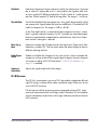
Tempo Sync Plug-Ins . . . . . . . . . . . . . . . . . . . . . . . . . . . . . . . . . . . . . . . . . . . . . . . . . . . . . . . . . . . 95
Available Note Values . . . . . . . . . . . . . . . . . . . . . . . . . . . . . . . . . . . . . . . . . . . . . . . . . . . . . . . . . 96
Range Limits . . . . . . . . . . . . . . . . . . . . . . . . . . . . . . . . . . . . . . . . . . . . . . . . . . . . . . . . . . . . . . . . . . 97
Entering Values . . . . . . . . . . . . . . . . . . . . . . . . . . . . . . . . . . . . . . . . . . . . . . . . . . . . . . . . . . . . . . . 97
Out of range . . . . . . . . . . . . . . . . . . . . . . . . . . . . . . . . . . . . . . . . . . . . . . . . . . . . . . . . . . . . . . . . . 98
Modes with Tempo Sync . . . . . . . . . . . . . . . . . . . . . . . . . . . . . . . . . . . . . . . . . . . . . . . . . . . . . . . . 98
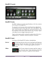
Roland RE-201 Sync . . . . . . . . . . . . . . . . . . . . . . . . . . . . . . . . . . . . . . . . . . . . . . . . . . . . . . . . . . . 99
Chapter 9. UAD Delay Compensation . . . . . . . . . . . . . . . . . . . . . . . . . . . . . .
100
Latency & Delay Compensation . . . . . . . . . . . . . . . . . . . . . . . . . . . . . . . . . . . . . . . . . . . . . . . . . 100
Host PDC Implementation . . . . . . . . . . . . . . . . . . . . . . . . . . . . . . . . . . . . . . . . . . . . . . . . . . . . . . 100
UAD-1 Delay Compensator . . . . . . . . . . . . . . . . . . . . . . . . . . . . . . . . . . . . . . . . . . . . . . . . . . . . 102
DelayComp Examples . . . . . . . . . . . . . . . . . . . . . . . . . . . . . . . . . . . . . . . . . . . . . . . . . . . . . . . . . 104
UAD-1 Track Advance . . . . . . . . . . . . . . . . . . . . . . . . . . . . . . . . . . . . . . . . . . . . . . . . . . . . . . . . 105
TrackAdv Examples . . . . . . . . . . . . . . . . . . . . . . . . . . . . . . . . . . . . . . . . . . . . . . . . . . . . . . . . . . . 106
Compensating Upsampled Plug-Ins . . . . . . . . . . . . . . . . . . . . . . . . . . . . . . . . . . . . . . . . . . . . . . 107
Upsampling Values Table . . . . . . . . . . . . . . . . . . . . . . . . . . . . . . . . . . . . . . . . . . . . . . . . . . . . . . 109
Upsampled Compensation Examples . . . . . . . . . . . . . . . . . . . . . . . . . . . . . . . . . . . . . . . . . . . . . 110
Live Processing . . . . . . . . . . . . . . . . . . . . . . . . . . . . . . . . . . . . . . . . . . . . . . . . . . . . . . . . . . . . . . . 112
Chapter 10. UAD ExpressCard Products . . . . . . . . . . . . . . . . . . . . . . . . . . . .
113
Overview . . . . . . . . . . . . . . . . . . . . . . . . . . . . . . . . . . . . . . . . . . . . . . . . . . . . . . . . . . . . . . . . . . . 113
UAD-2 SOLO/Laptop Details . . . . . . . . . . . . . . . . . . . . . . . . . . . . . . . . . . . . . . . . . . . . . . . . . . . 115
Important SOLO/Laptop Notes . . . . . . . . . . . . . . . . . . . . . . . . . . . . . . . . . . . . . . . . . . . . . . . . . 118
UAD–Xtenda . . . . . . . . . . . . . . . . . . . . . . . . . . . . . . . . . . . . . . . . . . . . . . . . . . . . . . . . . . . . . . . . 119
UAD–Xpander Details . . . . . . . . . . . . . . . . . . . . . . . . . . . . . . . . . . . . . . . . . . . . . . . . . . . . . . . . . 120
UAD–Xpander Connections . . . . . . . . . . . . . . . . . . . . . . . . . . . . . . . . . . . . . . . . . . . . . . . . . . . . 122
Xpander Operation . . . . . . . . . . . . . . . . . . . . . . . . . . . . . . . . . . . . . . . . . . . . . . . . . . . . . . . . . . . 122
Important Xpander Notes . . . . . . . . . . . . . . . . . . . . . . . . . . . . . . . . . . . . . . . . . . . . . . . . . . . . . . 126
Chapter 11. UAD-2 Satellite . . . . . . . . . . . . . . . . . . . . . . . . . . . . . . . . . . . . .
127
Overview . . . . . . . . . . . . . . . . . . . . . . . . . . . . . . . . . . . . . . . . . . . . . . . . . . . . . . . . . . . . . . . . . . . 127
UAD-2 Satellite Details . . . . . . . . . . . . . . . . . . . . . . . . . . . . . . . . . . . . . . . . . . . . . . . . . . . . . . . . 128
UAD-2 Satellite Installation . . . . . . . . . . . . . . . . . . . . . . . . . . . . . . . . . . . . . . . . . . . . . . . . . . . . . 129
UAD-2 Satellite Operation . . . . . . . . . . . . . . . . . . . . . . . . . . . . . . . . . . . . . . . . . . . . . . . . . . . . . 132
Important UAD-2 Satellite Notes . . . . . . . . . . . . . . . . . . . . . . . . . . . . . . . . . . . . . . . . . . . . . . . . 134
FireWire Basics . . . . . . . . . . . . . . . . . . . . . . . . . . . . . . . . . . . . . . . . . . . . . . . . . . . . . . . . . . . . . . 136
FireWire Bandwidth . . . . . . . . . . . . . . . . . . . . . . . . . . . . . . . . . . . . . . . . . . . . . . . . . . . . . . . . . . 140
FireWire Bandwidth vs. UAD DSP . . . . . . . . . . . . . . . . . . . . . . . . . . . . . . . . . . . . . . . . . . . . . . . 142
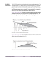
FireWire Bus Power . . . . . . . . . . . . . . . . . . . . . . . . . . . . . . . . . . . . . . . . . . . . . . . . . . . . . . . . . . . 143
UAD Powered Plug-Ins Manual
-7-
Table of Contents
TABLE OF CONTENTS
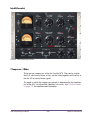
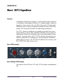
Chapter 12. Cambridge EQ. . . . . . . . . . . . . . . . . . . . . . . . . . . . . . . . . . . . . .
145
Overview . . . . . . . . . . . . . . . . . . . . . . . . . . . . . . . . . . . . . . . . . . . . . . . . . . . . . . . . . . . . . . . . . . . 145
Cambridge EQ Screenshot . . . . . . . . . . . . . . . . . . . . . . . . . . . . . . . . . . . . . . . . . . . . . . . . . . . . . 145
Cambridge EQ Controls . . . . . . . . . . . . . . . . . . . . . . . . . . . . . . . . . . . . . . . . . . . . . . . . . . . . . . . 146
Low Cut / High Cut Filters . . . . . . . . . . . . . . . . . . . . . . . . . . . . . . . . . . . . . . . . . . . . . . . . . . . . . 149
EQ Bands . . . . . . . . . . . . . . . . . . . . . . . . . . . . . . . . . . . . . . . . . . . . . . . . . . . . . . . . . . . . . . . . . . . 150
Parametric EQ . . . . . . . . . . . . . . . . . . . . . . . . . . . . . . . . . . . . . . . . . . . . . . . . . . . . . . . . . . . . . . . 151
Shelf EQ . . . . . . . . . . . . . . . . . . . . . . . . . . . . . . . . . . . . . . . . . . . . . . . . . . . . . . . . . . . . . . . . . . . . 154
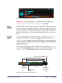
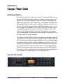
Chapter 13. Cooper Time Cube . . . . . . . . . . . . . . . . . . . . . . . . . . . . . . . . . . .
156
Dual Mechanical Delay Line . . . . . . . . . . . . . . . . . . . . . . . . . . . . . . . . . . . . . . . . . . . . . . . . . . . . 156
Cooper Time Cube Screenshot . . . . . . . . . . . . . . . . . . . . . . . . . . . . . . . . . . . . . . . . . . . . . . . . . . 156
Design Overview . . . . . . . . . . . . . . . . . . . . . . . . . . . . . . . . . . . . . . . . . . . . . . . . . . . . . . . . . . . . . 157
Cooper Time Cube Controls . . . . . . . . . . . . . . . . . . . . . . . . . . . . . . . . . . . . . . . . . . . . . . . . . . . . 157
Channel Controls . . . . . . . . . . . . . . . . . . . . . . . . . . . . . . . . . . . . . . . . . . . . . . . . . . . . . . . . . . . . . 160
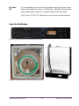
Cooper Time Cube Hardware . . . . . . . . . . . . . . . . . . . . . . . . . . . . . . . . . . . . . . . . . . . . . . . . . . 161
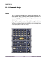
Chapter 14. CS-1 Channel Strip . . . . . . . . . . . . . . . . . . . . . . . . . . . . . . . . . .
162
Overview . . . . . . . . . . . . . . . . . . . . . . . . . . . . . . . . . . . . . . . . . . . . . . . . . . . . . . . . . . . . . . . . . . . 162
EX-1 Equalizer and Compressor . . . . . . . . . . . . . . . . . . . . . . . . . . . . . . . . . . . . . . . . . . . . . . . . 163
EX-1 Equalizer Controls . . . . . . . . . . . . . . . . . . . . . . . . . . . . . . . . . . . . . . . . . . . . . . . . . . . . . . . 163
EX-1 Compressor Controls . . . . . . . . . . . . . . . . . . . . . . . . . . . . . . . . . . . . . . . . . . . . . . . . . . . . . 164
EX-1M Overview . . . . . . . . . . . . . . . . . . . . . . . . . . . . . . . . . . . . . . . . . . . . . . . . . . . . . . . . . . . . . 165
DM-1 Delay Modulator . . . . . . . . . . . . . . . . . . . . . . . . . . . . . . . . . . . . . . . . . . . . . . . . . . . . . . . . 166
DM-1 Controls . . . . . . . . . . . . . . . . . . . . . . . . . . . . . . . . . . . . . . . . . . . . . . . . . . . . . . . . . . . . . . . 166
DM-1L . . . . . . . . . . . . . . . . . . . . . . . . . . . . . . . . . . . . . . . . . . . . . . . . . . . . . . . . . . . . . . . . . . . . . 168
RS-1 Reflection Engine . . . . . . . . . . . . . . . . . . . . . . . . . . . . . . . . . . . . . . . . . . . . . . . . . . . . . . . . 169
RS-1 Controls . . . . . . . . . . . . . . . . . . . . . . . . . . . . . . . . . . . . . . . . . . . . . . . . . . . . . . . . . . . . . . . . 170
Chapter 15. dbx 160 Compressor/Limiter . . . . . . . . . . . . . . . . . . . . . . . . . .
172
Overview . . . . . . . . . . . . . . . . . . . . . . . . . . . . . . . . . . . . . . . . . . . . . . . . . . . . . . . . . . . . . . . . . . . 172
dbx 160 Screenshot . . . . . . . . . . . . . . . . . . . . . . . . . . . . . . . . . . . . . . . . . . . . . . . . . . . . . . . . . . 172
dbx 160 Controls . . . . . . . . . . . . . . . . . . . . . . . . . . . . . . . . . . . . . . . . . . . . . . . . . . . . . . . . . . . . 173
WebZine Articles . . . . . . . . . . . . . . . . . . . . . . . . . . . . . . . . . . . . . . . . . . . . . . . . . . . . . . . . . . . . . 174
Chapter 16. DreamVerb . . . . . . . . . . . . . . . . . . . . . . . . . . . . . . . . . . . . . . . .
175
Overview . . . . . . . . . . . . . . . . . . . . . . . . . . . . . . . . . . . . . . . . . . . . . . . . . . . . . . . . . . . . . . . . . . . 175
Signal Flow . . . . . . . . . . . . . . . . . . . . . . . . . . . . . . . . . . . . . . . . . . . . . . . . . . . . . . . . . . . . . . . . . 176
Resonance (Equalization) Panel . . . . . . . . . . . . . . . . . . . . . . . . . . . . . . . . . . . . . . . . . . . . . . . . . 177
Shape Panel . . . . . . . . . . . . . . . . . . . . . . . . . . . . . . . . . . . . . . . . . . . . . . . . . . . . . . . . . . . . . . . . . 179
Materials Panel . . . . . . . . . . . . . . . . . . . . . . . . . . . . . . . . . . . . . . . . . . . . . . . . . . . . . . . . . . . . . . 181
UAD Powered Plug-Ins Manual
-8-
Table of Contents
TABLE OF CONTENTS
Reflections Panel . . . . . . . . . . . . . . . . . . . . . . . . . . . . . . . . . . . . . . . . . . . . . . . . . . . . . . . . . . . . . 183
Reverberation Panel . . . . . . . . . . . . . . . . . . . . . . . . . . . . . . . . . . . . . . . . . . . . . . . . . . . . . . . . . . 185
Positioning Panel . . . . . . . . . . . . . . . . . . . . . . . . . . . . . . . . . . . . . . . . . . . . . . . . . . . . . . . . . . . . . 186
Levels Panel . . . . . . . . . . . . . . . . . . . . . . . . . . . . . . . . . . . . . . . . . . . . . . . . . . . . . . . . . . . . . . . . . 188
DreamVerb Preset Management . . . . . . . . . . . . . . . . . . . . . . . . . . . . . . . . . . . . . . . . . . . . . . . . 189
Spatial Characteristics. . . . . . . . . . . . . . . . . . . . . . . . . . . . . . . . . . . . . . . . . . . . . . . . . . . . . . . . . 190
Preset Design Tips . . . . . . . . . . . . . . . . . . . . . . . . . . . . . . . . . . . . . . . . . . . . . . . . . . . . . . . . . . . . 191
Chapter 17. Empirical Labs EL7 FATSO . . . . . . . . . . . . . . . . . . . . . . . . . . . . .
193
Introduction . . . . . . . . . . . . . . . . . . . . . . . . . . . . . . . . . . . . . . . . . . . . . . . . . . . . . . . . . . . . . . . . . 193
FATSO Screenshots . . . . . . . . . . . . . . . . . . . . . . . . . . . . . . . . . . . . . . . . . . . . . . . . . . . . . . . . . . 194
FATSO Functional Overview . . . . . . . . . . . . . . . . . . . . . . . . . . . . . . . . . . . . . . . . . . . . . . . . . . . 194
FATSO Controls . . . . . . . . . . . . . . . . . . . . . . . . . . . . . . . . . . . . . . . . . . . . . . . . . . . . . . . . . . . . . . 197
Channel Controls . . . . . . . . . . . . . . . . . . . . . . . . . . . . . . . . . . . . . . . . . . . . . . . . . . . . . . . . . . . . . 198
Global Controls . . . . . . . . . . . . . . . . . . . . . . . . . . . . . . . . . . . . . . . . . . . . . . . . . . . . . . . . . . . . . . 201
FATSO Sr. Controls . . . . . . . . . . . . . . . . . . . . . . . . . . . . . . . . . . . . . . . . . . . . . . . . . . . . . . . . . . . 202
WebZine Article . . . . . . . . . . . . . . . . . . . . . . . . . . . . . . . . . . . . . . . . . . . . . . . . . . . . . . . . . . . . . 205
Chapter 18. EMT 140 Plate Reverb . . . . . . . . . . . . . . . . . . . . . . . . . . . . . . . .
206
Overview . . . . . . . . . . . . . . . . . . . . . . . . . . . . . . . . . . . . . . . . . . . . . . . . . . . . . . . . . . . . . . . . . . . 206
EMT 140 Screenshot . . . . . . . . . . . . . . . . . . . . . . . . . . . . . . . . . . . . . . . . . . . . . . . . . . . . . . . . . . 206
EMT 140 Controls . . . . . . . . . . . . . . . . . . . . . . . . . . . . . . . . . . . . . . . . . . . . . . . . . . . . . . . . . . . . 207
Reverb Controls . . . . . . . . . . . . . . . . . . . . . . . . . . . . . . . . . . . . . . . . . . . . . . . . . . . . . . . . . . . . . . 208
Stereo Controls . . . . . . . . . . . . . . . . . . . . . . . . . . . . . . . . . . . . . . . . . . . . . . . . . . . . . . . . . . . . . . 209
EQ Controls . . . . . . . . . . . . . . . . . . . . . . . . . . . . . . . . . . . . . . . . . . . . . . . . . . . . . . . . . . . . . . . . . 209
Modulation Controls . . . . . . . . . . . . . . . . . . . . . . . . . . . . . . . . . . . . . . . . . . . . . . . . . . . . . . . . . . 210
Blend Controls . . . . . . . . . . . . . . . . . . . . . . . . . . . . . . . . . . . . . . . . . . . . . . . . . . . . . . . . . . . . . . . 211
Chapter 19. EMT 250 Electronic Reverberator . . . . . . . . . . . . . . . . . . . . . . . .
213
Introduction . . . . . . . . . . . . . . . . . . . . . . . . . . . . . . . . . . . . . . . . . . . . . . . . . . . . . . . . . . . . . . . . . 213
EMT 250 Screenshot . . . . . . . . . . . . . . . . . . . . . . . . . . . . . . . . . . . . . . . . . . . . . . . . . . . . . . . . . . 214
Functional Overview . . . . . . . . . . . . . . . . . . . . . . . . . . . . . . . . . . . . . . . . . . . . . . . . . . . . . . . . . . 214
Program Mode Controls . . . . . . . . . . . . . . . . . . . . . . . . . . . . . . . . . . . . . . . . . . . . . . . . . . . . . . . 217
Global Controls . . . . . . . . . . . . . . . . . . . . . . . . . . . . . . . . . . . . . . . . . . . . . . . . . . . . . . . . . . . . . . 224
Webzine Article. . . . . . . . . . . . . . . . . . . . . . . . . . . . . . . . . . . . . . . . . . . . . . . . . . . . . . . . . . . . . . 225
Chapter 20. EP-34 Classic Tape Echo. . . . . . . . . . . . . . . . . . . . . . . . . . . . . . .
227
EP-34 Overview. . . . . . . . . . . . . . . . . . . . . . . . . . . . . . . . . . . . . . . . . . . . . . . . . . . . . . . . . . . . . . 227
EP-34 Tape Echo Screenshot . . . . . . . . . . . . . . . . . . . . . . . . . . . . . . . . . . . . . . . . . . . . . . . . . . . 228
EP-34 Controls . . . . . . . . . . . . . . . . . . . . . . . . . . . . . . . . . . . . . . . . . . . . . . . . . . . . . . . . . . . . . . . 228
EP-34 Hardware History . . . . . . . . . . . . . . . . . . . . . . . . . . . . . . . . . . . . . . . . . . . . . . . . . . . . . . . 232
UAD Powered Plug-Ins Manual
-9-
Table of Contents
TABLE OF CONTENTS
WebZine Article . . . . . . . . . . . . . . . . . . . . . . . . . . . . . . . . . . . . . . . . . . . . . . . . . . . . . . . . . . . . . 233
Chapter 21. Fairchild 670. . . . . . . . . . . . . . . . . . . . . . . . . . . . . . . . . . . . . . .
234
Overview . . . . . . . . . . . . . . . . . . . . . . . . . . . . . . . . . . . . . . . . . . . . . . . . . . . . . . . . . . . . . . . . . . . 234
Fairchild Screenshot . . . . . . . . . . . . . . . . . . . . . . . . . . . . . . . . . . . . . . . . . . . . . . . . . . . . . . . . . . 235
2 Compressors, 4 Modes . . . . . . . . . . . . . . . . . . . . . . . . . . . . . . . . . . . . . . . . . . . . . . . . . . . . . . 235
Controls Overview . . . . . . . . . . . . . . . . . . . . . . . . . . . . . . . . . . . . . . . . . . . . . . . . . . . . . . . . . . . . 236
Fairchild Modes . . . . . . . . . . . . . . . . . . . . . . . . . . . . . . . . . . . . . . . . . . . . . . . . . . . . . . . . . . . . . . 237
Controls . . . . . . . . . . . . . . . . . . . . . . . . . . . . . . . . . . . . . . . . . . . . . . . . . . . . . . . . . . . . . . . . . . . . 238
Chapter 22. Harrison 32C EQ . . . . . . . . . . . . . . . . . . . . . . . . . . . . . . . . . . . .
242
Overview . . . . . . . . . . . . . . . . . . . . . . . . . . . . . . . . . . . . . . . . . . . . . . . . . . . . . . . . . . . . . . . . . . . 242
Harrison 32C EQ Screenshot . . . . . . . . . . . . . . . . . . . . . . . . . . . . . . . . . . . . . . . . . . . . . . . . . . . 242
Harrison 32C EQ and Harrison 32C SE Controls . . . . . . . . . . . . . . . . . . . . . . . . . . . . . . . . . . 243
Harrison 32C SE . . . . . . . . . . . . . . . . . . . . . . . . . . . . . . . . . . . . . . . . . . . . . . . . . . . . . . . . . . . . . 245
Harrison 32C Latency . . . . . . . . . . . . . . . . . . . . . . . . . . . . . . . . . . . . . . . . . . . . . . . . . . . . . . . . . 246
WebZine Article . . . . . . . . . . . . . . . . . . . . . . . . . . . . . . . . . . . . . . . . . . . . . . . . . . . . . . . . . . . . . 246
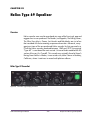
Chapter 23. Helios Type 69 Equalizer . . . . . . . . . . . . . . . . . . . . . . . . . . . . . .
247
Overview . . . . . . . . . . . . . . . . . . . . . . . . . . . . . . . . . . . . . . . . . . . . . . . . . . . . . . . . . . . . . . . . . . . 247
Helios Type 69 Screenshot . . . . . . . . . . . . . . . . . . . . . . . . . . . . . . . . . . . . . . . . . . . . . . . . . . . . . 247
Helios Type 69 Controls . . . . . . . . . . . . . . . . . . . . . . . . . . . . . . . . . . . . . . . . . . . . . . . . . . . . . . . 248
Helios 69 Latency . . . . . . . . . . . . . . . . . . . . . . . . . . . . . . . . . . . . . . . . . . . . . . . . . . . . . . . . . . . . 251
WebZine Article . . . . . . . . . . . . . . . . . . . . . . . . . . . . . . . . . . . . . . . . . . . . . . . . . . . . . . . . . . . . . 251
Chapter 24. LA-2A and 1176LN . . . . . . . . . . . . . . . . . . . . . . . . . . . . . . . . . .
253
Overview . . . . . . . . . . . . . . . . . . . . . . . . . . . . . . . . . . . . . . . . . . . . . . . . . . . . . . . . . . . . . . . . . . . 253
Compressor Basics . . . . . . . . . . . . . . . . . . . . . . . . . . . . . . . . . . . . . . . . . . . . . . . . . . . . . . . . . . . 253
Teletronix LA-2A Leveling Amplifier . . . . . . . . . . . . . . . . . . . . . . . . . . . . . . . . . . . . . . . . . . . . . . 256
LA-2A Controls . . . . . . . . . . . . . . . . . . . . . . . . . . . . . . . . . . . . . . . . . . . . . . . . . . . . . . . . . . . . . . 257
1176LN Solid-State Limiting Amplifier . . . . . . . . . . . . . . . . . . . . . . . . . . . . . . . . . . . . . . . . . . . 258
1176LN Controls . . . . . . . . . . . . . . . . . . . . . . . . . . . . . . . . . . . . . . . . . . . . . . . . . . . . . . . . . . . . . 259
1176SE “Special Edition” . . . . . . . . . . . . . . . . . . . . . . . . . . . . . . . . . . . . . . . . . . . . . . . . . . . . . . 261
Chapter 25. LA-3A Compressor . . . . . . . . . . . . . . . . . . . . . . . . . . . . . . . . . .
262
Overview . . . . . . . . . . . . . . . . . . . . . . . . . . . . . . . . . . . . . . . . . . . . . . . . . . . . . . . . . . . . . . . . . . . 262
LA-3A Screenshot . . . . . . . . . . . . . . . . . . . . . . . . . . . . . . . . . . . . . . . . . . . . . . . . . . . . . . . . . . . . 262
LA-3A Controls . . . . . . . . . . . . . . . . . . . . . . . . . . . . . . . . . . . . . . . . . . . . . . . . . . . . . . . . . . . . . . 263
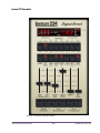
Chapter 26. Lexicon 224 . . . . . . . . . . . . . . . . . . . . . . . . . . . . . . . . . . . . . . .
264
Classic Digital Reverb . . . . . . . . . . . . . . . . . . . . . . . . . . . . . . . . . . . . . . . . . . . . . . . . . . . . . . . . . 264
Lexicon 224 Screenshot . . . . . . . . . . . . . . . . . . . . . . . . . . . . . . . . . . . . . . . . . . . . . . . . . . . . . . . 266
UAD Powered Plug-Ins Manual
- 10 -
Table of Contents
TABLE OF CONTENTS
Operational Overview . . . . . . . . . . . . . . . . . . . . . . . . . . . . . . . . . . . . . . . . . . . . . . . . . . . . . . . . 267
Primary Controls . . . . . . . . . . . . . . . . . . . . . . . . . . . . . . . . . . . . . . . . . . . . . . . . . . . . . . . . . . . . . 271
Hidden Controls. . . . . . . . . . . . . . . . . . . . . . . . . . . . . . . . . . . . . . . . . . . . . . . . . . . . . . . . . . . . . . 278
Program Descriptions . . . . . . . . . . . . . . . . . . . . . . . . . . . . . . . . . . . . . . . . . . . . . . . . . . . . . . . . . 281
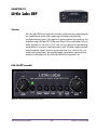
Chapter 27. Little Labs IBP . . . . . . . . . . . . . . . . . . . . . . . . . . . . . . . . . . . . . .
284
Overview . . . . . . . . . . . . . . . . . . . . . . . . . . . . . . . . . . . . . . . . . . . . . . . . . . . . . . . . . . . . . . . . . . . 284
Little Labs IBP Screenshot . . . . . . . . . . . . . . . . . . . . . . . . . . . . . . . . . . . . . . . . . . . . . . . . . . . . . . 284
Little Labs IBP Controls . . . . . . . . . . . . . . . . . . . . . . . . . . . . . . . . . . . . . . . . . . . . . . . . . . . . . . . . . 285
Little Labs IBP Latency . . . . . . . . . . . . . . . . . . . . . . . . . . . . . . . . . . . . . . . . . . . . . . . . . . . . . . . . . 286
WebZine article . . . . . . . . . . . . . . . . . . . . . . . . . . . . . . . . . . . . . . . . . . . . . . . . . . . . . . . . . . . . . . 286
Chapter 28. Manley Massive Passive EQ . . . . . . . . . . . . . . . . . . . . . . . . . . .
287
Overview . . . . . . . . . . . . . . . . . . . . . . . . . . . . . . . . . . . . . . . . . . . . . . . . . . . . . . . . . . . . . . . . . . . 287
Massive Passive Screenshots . . . . . . . . . . . . . . . . . . . . . . . . . . . . . . . . . . . . . . . . . . . . . . . . . . . 288
Unusual EQ Conventions . . . . . . . . . . . . . . . . . . . . . . . . . . . . . . . . . . . . . . . . . . . . . . . . . . . . . . 288
Massive Passive Mastering EQ . . . . . . . . . . . . . . . . . . . . . . . . . . . . . . . . . . . . . . . . . . . . . . . . . . 289
Standard vs. Mastering Versions . . . . . . . . . . . . . . . . . . . . . . . . . . . . . . . . . . . . . . . . . . . . . . . . 290
Massive Passive Band Controls. . . . . . . . . . . . . . . . . . . . . . . . . . . . . . . . . . . . . . . . . . . . . . . . . . 290
Channel Controls . . . . . . . . . . . . . . . . . . . . . . . . . . . . . . . . . . . . . . . . . . . . . . . . . . . . . . . . . . . . . 294
Other Controls . . . . . . . . . . . . . . . . . . . . . . . . . . . . . . . . . . . . . . . . . . . . . . . . . . . . . . . . . . . . . . . 296
Massive Passive Latency . . . . . . . . . . . . . . . . . . . . . . . . . . . . . . . . . . . . . . . . . . . . . . . . . . . . . . . 297
Notes from Manley Laboratories . . . . . . . . . . . . . . . . . . . . . . . . . . . . . . . . . . . . . . . . . . . . . . . . 297
Additional Information . . . . . . . . . . . . . . . . . . . . . . . . . . . . . . . . . . . . . . . . . . . . . . . . . . . . . . . . 299
Chapter 29. Moog Multimode Filter . . . . . . . . . . . . . . . . . . . . . . . . . . . . . . .
300
Overview . . . . . . . . . . . . . . . . . . . . . . . . . . . . . . . . . . . . . . . . . . . . . . . . . . . . . . . . . . . . . . . . . . . 300
Moog Filter Screenshot . . . . . . . . . . . . . . . . . . . . . . . . . . . . . . . . . . . . . . . . . . . . . . . . . . . . . . . . 301
Moog Filter Controls . . . . . . . . . . . . . . . . . . . . . . . . . . . . . . . . . . . . . . . . . . . . . . . . . . . . . . . . . . 301
Moog Filter SE . . . . . . . . . . . . . . . . . . . . . . . . . . . . . . . . . . . . . . . . . . . . . . . . . . . . . . . . . . . . . . . 307
Moog Filter Latency . . . . . . . . . . . . . . . . . . . . . . . . . . . . . . . . . . . . . . . . . . . . . . . . . . . . . . . . . . . 308
WebZine Articles . . . . . . . . . . . . . . . . . . . . . . . . . . . . . . . . . . . . . . . . . . . . . . . . . . . . . . . . . . . . . 308
Chapter 30. Neve 1073 Equalizer. . . . . . . . . . . . . . . . . . . . . . . . . . . . . . . . .
309
Overview . . . . . . . . . . . . . . . . . . . . . . . . . . . . . . . . . . . . . . . . . . . . . . . . . . . . . . . . . . . . . . . . . . . 309
Neve 1073 Screenshot . . . . . . . . . . . . . . . . . . . . . . . . . . . . . . . . . . . . . . . . . . . . . . . . . . . . . . . . 309
Neve 1073 and 1073SE Controls . . . . . . . . . . . . . . . . . . . . . . . . . . . . . . . . . . . . . . . . . . . . . . . 309
Neve 1073SE . . . . . . . . . . . . . . . . . . . . . . . . . . . . . . . . . . . . . . . . . . . . . . . . . . . . . . . . . . . . . . . 312
Neve 1073 Latency . . . . . . . . . . . . . . . . . . . . . . . . . . . . . . . . . . . . . . . . . . . . . . . . . . . . . . . . . . . 313
UAD Powered Plug-Ins Manual
- 11 -
Table of Contents
TABLE OF CONTENTS
Chapter 31. Neve 1081 Equalizer. . . . . . . . . . . . . . . . . . . . . . . . . . . . . . . . .
314
Overview . . . . . . . . . . . . . . . . . . . . . . . . . . . . . . . . . . . . . . . . . . . . . . . . . . . . . . . . . . . . . . . . . . . 314
Neve 1081 Screenshot . . . . . . . . . . . . . . . . . . . . . . . . . . . . . . . . . . . . . . . . . . . . . . . . . . . . . . . . 314
Neve 1081 and 1081SE Controls . . . . . . . . . . . . . . . . . . . . . . . . . . . . . . . . . . . . . . . . . . . . . . . 315
Neve 1081SE . . . . . . . . . . . . . . . . . . . . . . . . . . . . . . . . . . . . . . . . . . . . . . . . . . . . . . . . . . . . . . . 320
Neve 1081 Latency . . . . . . . . . . . . . . . . . . . . . . . . . . . . . . . . . . . . . . . . . . . . . . . . . . . . . . . . . . . 320
Chapter 32. Neve 31102 Console EQ . . . . . . . . . . . . . . . . . . . . . . . . . . . . . .
321
Overview . . . . . . . . . . . . . . . . . . . . . . . . . . . . . . . . . . . . . . . . . . . . . . . . . . . . . . . . . . . . . . . . . . . 321
Neve 31102 Screenshot . . . . . . . . . . . . . . . . . . . . . . . . . . . . . . . . . . . . . . . . . . . . . . . . . . . . . . . 321
Neve 31102 and 31102SE Controls . . . . . . . . . . . . . . . . . . . . . . . . . . . . . . . . . . . . . . . . . . . . . 322
Neve 31102SE . . . . . . . . . . . . . . . . . . . . . . . . . . . . . . . . . . . . . . . . . . . . . . . . . . . . . . . . . . . . . . 325
Neve 31102 Latency . . . . . . . . . . . . . . . . . . . . . . . . . . . . . . . . . . . . . . . . . . . . . . . . . . . . . . . . . . 326
Chapter 33. Neve 33609 Compressor . . . . . . . . . . . . . . . . . . . . . . . . . . . . .
327
Overview . . . . . . . . . . . . . . . . . . . . . . . . . . . . . . . . . . . . . . . . . . . . . . . . . . . . . . . . . . . . . . . . . . . 327
Neve 33609 Screenshot . . . . . . . . . . . . . . . . . . . . . . . . . . . . . . . . . . . . . . . . . . . . . . . . . . . . . . . 328
Operation . . . . . . . . . . . . . . . . . . . . . . . . . . . . . . . . . . . . . . . . . . . . . . . . . . . . . . . . . . . . . . . . . . 328
Neve 33609 and 33609SE Controls . . . . . . . . . . . . . . . . . . . . . . . . . . . . . . . . . . . . . . . . . . . . . 329
Limiter . . . . . . . . . . . . . . . . . . . . . . . . . . . . . . . . . . . . . . . . . . . . . . . . . . . . . . . . . . . . . . . . . . . . . . 329
Compressor . . . . . . . . . . . . . . . . . . . . . . . . . . . . . . . . . . . . . . . . . . . . . . . . . . . . . . . . . . . . . . . . . 330
Other Controls . . . . . . . . . . . . . . . . . . . . . . . . . . . . . . . . . . . . . . . . . . . . . . . . . . . . . . . . . . . . . . . 331
Neve 33609SE . . . . . . . . . . . . . . . . . . . . . . . . . . . . . . . . . . . . . . . . . . . . . . . . . . . . . . . . . . . . . . 336
Neve 33609 Latency . . . . . . . . . . . . . . . . . . . . . . . . . . . . . . . . . . . . . . . . . . . . . . . . . . . . . . . . . . 336
Chapter 34. Neve 88RS Channel Strip . . . . . . . . . . . . . . . . . . . . . . . . . . . . .
337
Overview . . . . . . . . . . . . . . . . . . . . . . . . . . . . . . . . . . . . . . . . . . . . . . . . . . . . . . . . . . . . . . . . . . . 337
Neve 88RS Screenshot . . . . . . . . . . . . . . . . . . . . . . . . . . . . . . . . . . . . . . . . . . . . . . . . . . . . . . . . 338
Neve 88RS Controls . . . . . . . . . . . . . . . . . . . . . . . . . . . . . . . . . . . . . . . . . . . . . . . . . . . . . . . . . . 339
Dynamics . . . . . . . . . . . . . . . . . . . . . . . . . . . . . . . . . . . . . . . . . . . . . . . . . . . . . . . . . . . . . . . . . . . 339
Gate/Expander . . . . . . . . . . . . . . . . . . . . . . . . . . . . . . . . . . . . . . . . . . . . . . . . . . . . . . . . . . . . . . 340
Limiter/Compressor. . . . . . . . . . . . . . . . . . . . . . . . . . . . . . . . . . . . . . . . . . . . . . . . . . . . . . . . . . . 343
EQ . . . . . . . . . . . . . . . . . . . . . . . . . . . . . . . . . . . . . . . . . . . . . . . . . . . . . . . . . . . . . . . . . . . . . . . . 346
Cut Filters . . . . . . . . . . . . . . . . . . . . . . . . . . . . . . . . . . . . . . . . . . . . . . . . . . . . . . . . . . . . . . . . . . . 349
Global . . . . . . . . . . . . . . . . . . . . . . . . . . . . . . . . . . . . . . . . . . . . . . . . . . . . . . . . . . . . . . . . . . . . . 350
WebZine Article . . . . . . . . . . . . . . . . . . . . . . . . . . . . . . . . . . . . . . . . . . . . . . . . . . . . . . . . . . . . . 351
Chapter 35. Nigel . . . . . . . . . . . . . . . . . . . . . . . . . . . . . . . . . . . . . . . . . . . .
352
Introduction . . . . . . . . . . . . . . . . . . . . . . . . . . . . . . . . . . . . . . . . . . . . . . . . . . . . . . . . . . . . . . . . . 352
Preflex Plug-in . . . . . . . . . . . . . . . . . . . . . . . . . . . . . . . . . . . . . . . . . . . . . . . . . . . . . . . . . . . . . . . 354
Preflex Modules . . . . . . . . . . . . . . . . . . . . . . . . . . . . . . . . . . . . . . . . . . . . . . . . . . . . . . . . . . . . . . 354
UAD Powered Plug-Ins Manual
- 12 -
Table of Contents
TABLE OF CONTENTS
Gate/Comp Module . . . . . . . . . . . . . . . . . . . . . . . . . . . . . . . . . . . . . . . . . . . . . . . . . . . . . . . . . . 355
Amp Module . . . . . . . . . . . . . . . . . . . . . . . . . . . . . . . . . . . . . . . . . . . . . . . . . . . . . . . . . . . . . . . . 358
Amp Controls . . . . . . . . . . . . . . . . . . . . . . . . . . . . . . . . . . . . . . . . . . . . . . . . . . . . . . . . . . . . . . . . 359
Cabinet Module . . . . . . . . . . . . . . . . . . . . . . . . . . . . . . . . . . . . . . . . . . . . . . . . . . . . . . . . . . . . . . 362
Phasor Module. . . . . . . . . . . . . . . . . . . . . . . . . . . . . . . . . . . . . . . . . . . . . . . . . . . . . . . . . . . . . . . 364
Mod Filter Module . . . . . . . . . . . . . . . . . . . . . . . . . . . . . . . . . . . . . . . . . . . . . . . . . . . . . . . . . . . . 367
TremModEcho plug-in . . . . . . . . . . . . . . . . . . . . . . . . . . . . . . . . . . . . . . . . . . . . . . . . . . . . . . . . . 371
Trem/Fade Module . . . . . . . . . . . . . . . . . . . . . . . . . . . . . . . . . . . . . . . . . . . . . . . . . . . . . . . . . . . 372
Mod Delay Module . . . . . . . . . . . . . . . . . . . . . . . . . . . . . . . . . . . . . . . . . . . . . . . . . . . . . . . . . . . 375
Echo Module . . . . . . . . . . . . . . . . . . . . . . . . . . . . . . . . . . . . . . . . . . . . . . . . . . . . . . . . . . . . . . . . 379
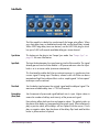
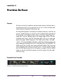
Chapter 36. Precision Buss Compressor . . . . . . . . . . . . . . . . . . . . . . . . . . . .
381
Overview . . . . . . . . . . . . . . . . . . . . . . . . . . . . . . . . . . . . . . . . . . . . . . . . . . . . . . . . . . . . . . . . . . . 381
Precision Buss Compressor Screenshot . . . . . . . . . . . . . . . . . . . . . . . . . . . . . . . . . . . . . . . . . . . 382
Precision Buss Compressor Controls . . . . . . . . . . . . . . . . . . . . . . . . . . . . . . . . . . . . . . . . . . . . . 382
Extra Presets . . . . . . . . . . . . . . . . . . . . . . . . . . . . . . . . . . . . . . . . . . . . . . . . . . . . . . . . . . . . . . . . . 386
WebZine Article . . . . . . . . . . . . . . . . . . . . . . . . . . . . . . . . . . . . . . . . . . . . . . . . . . . . . . . . . . . . . 386
Chapter 37. Precision De-Esser . . . . . . . . . . . . . . . . . . . . . . . . . . . . . . . . . . .
387
Overview . . . . . . . . . . . . . . . . . . . . . . . . . . . . . . . . . . . . . . . . . . . . . . . . . . . . . . . . . . . . . . . . . . . 387
Precision De-Esser Screenshot . . . . . . . . . . . . . . . . . . . . . . . . . . . . . . . . . . . . . . . . . . . . . . . . . . 387
Precision De-Esser Controls . . . . . . . . . . . . . . . . . . . . . . . . . . . . . . . . . . . . . . . . . . . . . . . . . . . . 388
Operating Tips . . . . . . . . . . . . . . . . . . . . . . . . . . . . . . . . . . . . . . . . . . . . . . . . . . . . . . . . . . . . . . . 390
Chapter 38. Precision Enhancer Hz . . . . . . . . . . . . . . . . . . . . . . . . . . . . . . . .
391
Overview . . . . . . . . . . . . . . . . . . . . . . . . . . . . . . . . . . . . . . . . . . . . . . . . . . . . . . . . . . . . . . . . . . . 391
Precision Enhancer Hz Screenshot . . . . . . . . . . . . . . . . . . . . . . . . . . . . . . . . . . . . . . . . . . . . . . . 391
Precision Enhancer Hz Controls . . . . . . . . . . . . . . . . . . . . . . . . . . . . . . . . . . . . . . . . . . . . . . . . . 392
Precision Enhancer Hz Usage Notes . . . . . . . . . . . . . . . . . . . . . . . . . . . . . . . . . . . . . . . . . . . . . 395
Chapter 39. Precision Enhancer kHz . . . . . . . . . . . . . . . . . . . . . . . . . . . . . . .
396
Overview . . . . . . . . . . . . . . . . . . . . . . . . . . . . . . . . . . . . . . . . . . . . . . . . . . . . . . . . . . . . . . . . . . . 396
Precision Enhancer kHz Screenshot . . . . . . . . . . . . . . . . . . . . . . . . . . . . . . . . . . . . . . . . . . . . . . 397
Precision Enhancer kHz Controls . . . . . . . . . . . . . . . . . . . . . . . . . . . . . . . . . . . . . . . . . . . . . . . . 397
Chapter 40. Precision Equalizer . . . . . . . . . . . . . . . . . . . . . . . . . . . . . . . . . .
400
Overview . . . . . . . . . . . . . . . . . . . . . . . . . . . . . . . . . . . . . . . . . . . . . . . . . . . . . . . . . . . . . . . . . . . 400
Precision Equalizer Screenshot . . . . . . . . . . . . . . . . . . . . . . . . . . . . . . . . . . . . . . . . . . . . . . . . . . 400
Precision Equalizer Controls . . . . . . . . . . . . . . . . . . . . . . . . . . . . . . . . . . . . . . . . . . . . . . . . . . . . 401
Control Grouping . . . . . . . . . . . . . . . . . . . . . . . . . . . . . . . . . . . . . . . . . . . . . . . . . . . . . . . . . . . . 401
Modes . . . . . . . . . . . . . . . . . . . . . . . . . . . . . . . . . . . . . . . . . . . . . . . . . . . . . . . . . . . . . . . . . . . . . 401
UAD Powered Plug-Ins Manual
- 13 -
Table of Contents
TABLE OF CONTENTS
Band Controls . . . . . . . . . . . . . . . . . . . . . . . . . . . . . . . . . . . . . . . . . . . . . . . . . . . . . . . . . . . . . . . 403
Precision Equalizer Latency . . . . . . . . . . . . . . . . . . . . . . . . . . . . . . . . . . . . . . . . . . . . . . . . . . . . 405
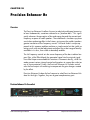
Chapter 41. Precision Limiter . . . . . . . . . . . . . . . . . . . . . . . . . . . . . . . . . . . .
406
Overview . . . . . . . . . . . . . . . . . . . . . . . . . . . . . . . . . . . . . . . . . . . . . . . . . . . . . . . . . . . . . . . . . . . 406
Precision Limiter Screenshot . . . . . . . . . . . . . . . . . . . . . . . . . . . . . . . . . . . . . . . . . . . . . . . . . . . . 407
Controls Overview . . . . . . . . . . . . . . . . . . . . . . . . . . . . . . . . . . . . . . . . . . . . . . . . . . . . . . . . . . . . 407
Precision Limiter Controls . . . . . . . . . . . . . . . . . . . . . . . . . . . . . . . . . . . . . . . . . . . . . . . . . . . . . . 407
Precision Limiter Meters Overview . . . . . . . . . . . . . . . . . . . . . . . . . . . . . . . . . . . . . . . . . . . . . . . 408
Precision Limiter Latency . . . . . . . . . . . . . . . . . . . . . . . . . . . . . . . . . . . . . . . . . . . . . . . . . . . . . . . 413
Chapter 42. Precision Maximizer . . . . . . . . . . . . . . . . . . . . . . . . . . . . . . . . .
414
Overview . . . . . . . . . . . . . . . . . . . . . . . . . . . . . . . . . . . . . . . . . . . . . . . . . . . . . . . . . . . . . . . . . . . 414
Precision Maximizer Screenshot . . . . . . . . . . . . . . . . . . . . . . . . . . . . . . . . . . . . . . . . . . . . . . . . . 415
Precision Maximizer Controls . . . . . . . . . . . . . . . . . . . . . . . . . . . . . . . . . . . . . . . . . . . . . . . . . . . 415
Operating Tips . . . . . . . . . . . . . . . . . . . . . . . . . . . . . . . . . . . . . . . . . . . . . . . . . . . . . . . . . . . . . . . 419
Precision Maximizer Latency . . . . . . . . . . . . . . . . . . . . . . . . . . . . . . . . . . . . . . . . . . . . . . . . . . . 419
WebZine Article . . . . . . . . . . . . . . . . . . . . . . . . . . . . . . . . . . . . . . . . . . . . . . . . . . . . . . . . . . . . . 420
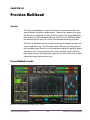
Chapter 43. Precision Multiband . . . . . . . . . . . . . . . . . . . . . . . . . . . . . . . . .
421
Overview . . . . . . . . . . . . . . . . . . . . . . . . . . . . . . . . . . . . . . . . . . . . . . . . . . . . . . . . . . . . . . . . . . . 421
Precision Multiband Screenshot . . . . . . . . . . . . . . . . . . . . . . . . . . . . . . . . . . . . . . . . . . . . . . . . . 421
Precision Multiband Interface . . . . . . . . . . . . . . . . . . . . . . . . . . . . . . . . . . . . . . . . . . . . . . . . . . . 422
Band Controls . . . . . . . . . . . . . . . . . . . . . . . . . . . . . . . . . . . . . . . . . . . . . . . . . . . . . . . . . . . . . . . 423
Band Parameters . . . . . . . . . . . . . . . . . . . . . . . . . . . . . . . . . . . . . . . . . . . . . . . . . . . . . . . . . . . . . 424
EQ Display . . . . . . . . . . . . . . . . . . . . . . . . . . . . . . . . . . . . . . . . . . . . . . . . . . . . . . . . . . . . . . . . . . 428
Frequency Controls . . . . . . . . . . . . . . . . . . . . . . . . . . . . . . . . . . . . . . . . . . . . . . . . . . . . . . . . . . . 430
Dynamics Meters . . . . . . . . . . . . . . . . . . . . . . . . . . . . . . . . . . . . . . . . . . . . . . . . . . . . . . . . . . . . . 431
Global Controls . . . . . . . . . . . . . . . . . . . . . . . . . . . . . . . . . . . . . . . . . . . . . . . . . . . . . . . . . . . . . . 432
Precision Multiband Latency . . . . . . . . . . . . . . . . . . . . . . . . . . . . . . . . . . . . . . . . . . . . . . . . . . . . 434
Chapter 44. Pultec and Pultec-Pro . . . . . . . . . . . . . . . . . . . . . . . . . . . . . . . .
435
Overview . . . . . . . . . . . . . . . . . . . . . . . . . . . . . . . . . . . . . . . . . . . . . . . . . . . . . . . . . . . . . . . . . . . 435
Pultec Latency. . . . . . . . . . . . . . . . . . . . . . . . . . . . . . . . . . . . . . . . . . . . . . . . . . . . . . . . . . . . . . . . 436
Pultec EQP-1A Screenshot . . . . . . . . . . . . . . . . . . . . . . . . . . . . . . . . . . . . . . . . . . . . . . . . . . . . . 436
Pultec EQP-1A Controls . . . . . . . . . . . . . . . . . . . . . . . . . . . . . . . . . . . . . . . . . . . . . . . . . . . . . . . 436
Low Frequency Controls . . . . . . . . . . . . . . . . . . . . . . . . . . . . . . . . . . . . . . . . . . . . . . . . . . . . . . . 437
High Frequency Controls . . . . . . . . . . . . . . . . . . . . . . . . . . . . . . . . . . . . . . . . . . . . . . . . . . . . . . 438
High Attenuation Controls . . . . . . . . . . . . . . . . . . . . . . . . . . . . . . . . . . . . . . . . . . . . . . . . . . . . . 438
Pultec MEQ-5 Screenshot . . . . . . . . . . . . . . . . . . . . . . . . . . . . . . . . . . . . . . . . . . . . . . . . . . . . . . 439
Pultec MEQ-5 Controls . . . . . . . . . . . . . . . . . . . . . . . . . . . . . . . . . . . . . . . . . . . . . . . . . . . . . . . . 439
UAD Powered Plug-Ins Manual
- 14 -
Table of Contents
TABLE OF CONTENTS
Low Peak Controls . . . . . . . . . . . . . . . . . . . . . . . . . . . . . . . . . . . . . . . . . . . . . . . . . . . . . . . . . . . . 440
Dip Controls . . . . . . . . . . . . . . . . . . . . . . . . . . . . . . . . . . . . . . . . . . . . . . . . . . . . . . . . . . . . . . . . . 440
High Peak Controls . . . . . . . . . . . . . . . . . . . . . . . . . . . . . . . . . . . . . . . . . . . . . . . . . . . . . . . . . . . 440
MEQ-5 Response Curves . . . . . . . . . . . . . . . . . . . . . . . . . . . . . . . . . . . . . . . . . . . . . . . . . . . . . . 440
Chapter 45. RealVerb Pro . . . . . . . . . . . . . . . . . . . . . . . . . . . . . . . . . . . . . .
444
Overview . . . . . . . . . . . . . . . . . . . . . . . . . . . . . . . . . . . . . . . . . . . . . . . . . . . . . . . . . . . . . . . . . . . 444
RealVerb Pro Background. . . . . . . . . . . . . . . . . . . . . . . . . . . . . . . . . . . . . . . . . . . . . . . . . . . . . . 445
Spectral Characteristics . . . . . . . . . . . . . . . . . . . . . . . . . . . . . . . . . . . . . . . . . . . . . . . . . . . . . . . . 446
Resonance (Equalization) . . . . . . . . . . . . . . . . . . . . . . . . . . . . . . . . . . . . . . . . . . . . . . . . . . . . . . 451
Timing . . . . . . . . . . . . . . . . . . . . . . . . . . . . . . . . . . . . . . . . . . . . . . . . . . . . . . . . . . . . . . . . . . . . . 452
Positioning . . . . . . . . . . . . . . . . . . . . . . . . . . . . . . . . . . . . . . . . . . . . . . . . . . . . . . . . . . . . . . . . . . 454
Levels . . . . . . . . . . . . . . . . . . . . . . . . . . . . . . . . . . . . . . . . . . . . . . . . . . . . . . . . . . . . . . . . . . . . . . 456
Morphing . . . . . . . . . . . . . . . . . . . . . . . . . . . . . . . . . . . . . . . . . . . . . . . . . . . . . . . . . . . . . . . . . . . 456
RealVerb Pro Preset Management . . . . . . . . . . . . . . . . . . . . . . . . . . . . . . . . . . . . . . . . . . . . . . . 458
RealVerb Pro Preset List . . . . . . . . . . . . . . . . . . . . . . . . . . . . . . . . . . . . . . . . . . . . . . . . . . . . . . . . 458
Chapter 46. Boss CE-1 Chorus Ensemble . . . . . . . . . . . . . . . . . . . . . . . . . . . .
460
Overview . . . . . . . . . . . . . . . . . . . . . . . . . . . . . . . . . . . . . . . . . . . . . . . . . . . . . . . . . . . . . . . . . . . 460
Boss CE-1 Screenshot . . . . . . . . . . . . . . . . . . . . . . . . . . . . . . . . . . . . . . . . . . . . . . . . . . . . . . . . . 460
Boss CE-1 Controls . . . . . . . . . . . . . . . . . . . . . . . . . . . . . . . . . . . . . . . . . . . . . . . . . . . . . . . . . . . 461
Chapter 47. Roland Dimension D . . . . . . . . . . . . . . . . . . . . . . . . . . . . . . . . .
464
Overview . . . . . . . . . . . . . . . . . . . . . . . . . . . . . . . . . . . . . . . . . . . . . . . . . . . . . . . . . . . . . . . . . . . 464
Roland Dimension D Screenshot . . . . . . . . . . . . . . . . . . . . . . . . . . . . . . . . . . . . . . . . . . . . . . . . 464
Roland Dimension D Controls . . . . . . . . . . . . . . . . . . . . . . . . . . . . . . . . . . . . . . . . . . . . . . . . . . . 465
Chapter 48. Roland RE-201 Space Echo . . . . . . . . . . . . . . . . . . . . . . . . . . . .
466
Overview . . . . . . . . . . . . . . . . . . . . . . . . . . . . . . . . . . . . . . . . . . . . . . . . . . . . . . . . . . . . . . . . . . . 466
Roland RE-201 Screenshot . . . . . . . . . . . . . . . . . . . . . . . . . . . . . . . . . . . . . . . . . . . . . . . . . . . . . 467
Roland RE-201 Interface . . . . . . . . . . . . . . . . . . . . . . . . . . . . . . . . . . . . . . . . . . . . . . . . . . . . . . . 467
Roland RE-201 Controls . . . . . . . . . . . . . . . . . . . . . . . . . . . . . . . . . . . . . . . . . . . . . . . . . . . . . . . 467
Chapter 49. SPL Transient Designer . . . . . . . . . . . . . . . . . . . . . . . . . . . . . . .
473
Overview . . . . . . . . . . . . . . . . . . . . . . . . . . . . . . . . . . . . . . . . . . . . . . . . . . . . . . . . . . . . . . . . . . . 473
SPL Transient Designer Screenshot . . . . . . . . . . . . . . . . . . . . . . . . . . . . . . . . . . . . . . . . . . . . . . . 473
SPL Transient Designer Controls . . . . . . . . . . . . . . . . . . . . . . . . . . . . . . . . . . . . . . . . . . . . . . . . . 474
WebZine Article . . . . . . . . . . . . . . . . . . . . . . . . . . . . . . . . . . . . . . . . . . . . . . . . . . . . . . . . . . . . . 475
Acknowledgement . . . . . . . . . . . . . . . . . . . . . . . . . . . . . . . . . . . . . . . . . . . . . . . . . . . . . . . . . . . . 476
Applications . . . . . . . . . . . . . . . . . . . . . . . . . . . . . . . . . . . . . . . . . . . . . . . . . . . . . . . . . . . . . . . . . 476
Technology . . . . . . . . . . . . . . . . . . . . . . . . . . . . . . . . . . . . . . . . . . . . . . . . . . . . . . . . . . . . . . . . . . 480
UAD Powered Plug-Ins Manual
- 15 -
Table of Contents
TABLE OF CONTENTS
Chapter 50. SSL E Channel Strip . . . . . . . . . . . . . . . . . . . . . . . . . . . . . . . . . .
484
Large Format Mix Module . . . . . . . . . . . . . . . . . . . . . . . . . . . . . . . . . . . . . . . . . . . . . . . . . . . . . 484
SSL E Channel Strip Screenshot . . . . . . . . . . . . . . . . . . . . . . . . . . . . . . . . . . . . . . . . . . . . . . . . . 485
SSL E Channel Strip Controls . . . . . . . . . . . . . . . . . . . . . . . . . . . . . . . . . . . . . . . . . . . . . . . . . . . 485
Filters . . . . . . . . . . . . . . . . . . . . . . . . . . . . . . . . . . . . . . . . . . . . . . . . . . . . . . . . . . . . . . . . . . . . . . 486
Dynamics . . . . . . . . . . . . . . . . . . . . . . . . . . . . . . . . . . . . . . . . . . . . . . . . . . . . . . . . . . . . . . . . . . . 487
Compressor/Limiter. . . . . . . . . . . . . . . . . . . . . . . . . . . . . . . . . . . . . . . . . . . . . . . . . . . . . . . . . . . 487
Gate/Expander . . . . . . . . . . . . . . . . . . . . . . . . . . . . . . . . . . . . . . . . . . . . . . . . . . . . . . . . . . . . . . 488
EQ . . . . . . . . . . . . . . . . . . . . . . . . . . . . . . . . . . . . . . . . . . . . . . . . . . . . . . . . . . . . . . . . . . . . . . . . 491
Global . . . . . . . . . . . . . . . . . . . . . . . . . . . . . . . . . . . . . . . . . . . . . . . . . . . . . . . . . . . . . . . . . . . . . 495
Usage Notes . . . . . . . . . . . . . . . . . . . . . . . . . . . . . . . . . . . . . . . . . . . . . . . . . . . . . . . . . . . . . . . . 496
WebZine Article . . . . . . . . . . . . . . . . . . . . . . . . . . . . . . . . . . . . . . . . . . . . . . . . . . . . . . . . . . . . . 497
Chapter 51. SSL G Bus Compressor. . . . . . . . . . . . . . . . . . . . . . . . . . . . . . . .
498
Large Format Console Dynamics . . . . . . . . . . . . . . . . . . . . . . . . . . . . . . . . . . . . . . . . . . . . . . . . 498
SSL G Bus Compressor Screenshot. . . . . . . . . . . . . . . . . . . . . . . . . . . . . . . . . . . . . . . . . . . . . . . 498
SSL G Bus Compressor Controls . . . . . . . . . . . . . . . . . . . . . . . . . . . . . . . . . . . . . . . . . . . . . . . . . 499
General Usage Notes . . . . . . . . . . . . . . . . . . . . . . . . . . . . . . . . . . . . . . . . . . . . . . . . . . . . . . . . . 501
WebZine Article . . . . . . . . . . . . . . . . . . . . . . . . . . . . . . . . . . . . . . . . . . . . . . . . . . . . . . . . . . . . . 502
Chapter 52. Studer A800 . . . . . . . . . . . . . . . . . . . . . . . . . . . . . . . . . . . . . . .
503
Multichannel Tape Recorder . . . . . . . . . . . . . . . . . . . . . . . . . . . . . . . . . . . . . . . . . . . . . . . . . . . . 503
Studer A800 Screenshot . . . . . . . . . . . . . . . . . . . . . . . . . . . . . . . . . . . . . . . . . . . . . . . . . . . . . . . 504
Operational Overview . . . . . . . . . . . . . . . . . . . . . . . . . . . . . . . . . . . . . . . . . . . . . . . . . . . . . . . . 504
Primary Controls . . . . . . . . . . . . . . . . . . . . . . . . . . . . . . . . . . . . . . . . . . . . . . . . . . . . . . . . . . . . . 507
Secondary Controls . . . . . . . . . . . . . . . . . . . . . . . . . . . . . . . . . . . . . . . . . . . . . . . . . . . . . . . . . . . 510
Studer A800 Latency. . . . . . . . . . . . . . . . . . . . . . . . . . . . . . . . . . . . . . . . . . . . . . . . . . . . . . . . . . 516
Chapter 53. Trident A-Range EQ. . . . . . . . . . . . . . . . . . . . . . . . . . . . . . . . . .
518
Overview . . . . . . . . . . . . . . . . . . . . . . . . . . . . . . . . . . . . . . . . . . . . . . . . . . . . . . . . . . . . . . . . . . . 518
Trident A-Range EQ Screenshot . . . . . . . . . . . . . . . . . . . . . . . . . . . . . . . . . . . . . . . . . . . . . . . . . 518
Operational Overview . . . . . . . . . . . . . . . . . . . . . . . . . . . . . . . . . . . . . . . . . . . . . . . . . . . . . . . . 519
Trident A-Range EQ Controls . . . . . . . . . . . . . . . . . . . . . . . . . . . . . . . . . . . . . . . . . . . . . . . . . . . 520
Trident A-Range Latency . . . . . . . . . . . . . . . . . . . . . . . . . . . . . . . . . . . . . . . . . . . . . . . . . . . . . . . 522
WebZine Article . . . . . . . . . . . . . . . . . . . . . . . . . . . . . . . . . . . . . . . . . . . . . . . . . . . . . . . . . . . . . 522
Chapter 54. History . . . . . . . . . . . . . . . . . . . . . . . . . . . . . . . . . . . . . . . . . . .
524
Bill Putnam Sr. . . . . . . . . . . . . . . . . . . . . . . . . . . . . . . . . . . . . . . . . . . . . . . . . . . . . . . . . . . . . . . . 524
Classic Compressors . . . . . . . . . . . . . . . . . . . . . . . . . . . . . . . . . . . . . . . . . . . . . . . . . . . . . . . . . . 528
Pros Talk UA . . . . . . . . . . . . . . . . . . . . . . . . . . . . . . . . . . . . . . . . . . . . . . . . . . . . . . . . . . . . . . . . 531
Thank You . . . . . . . . . . . . . . . . . . . . . . . . . . . . . . . . . . . . . . . . . . . . . . . . . . . . . . . . . . . . . . . . . . 535
UAD Powered Plug-Ins Manual
- 16 -
Table of Contents
CHAPTER 1
Introduction
Welcome!
Congratulations, and welcome to the UA Family! You now own the best
sounding, most powerful sonic upgrade available for your DAW. The UAD-2
and version 5 software represents the culmination of a multi-year development effort delivering the latest in state-of-the-art audio processing technology
and is the next evolution of the revolutionary, award-winning UAD-1 Powered
Plug-Ins & DSP Device Platform.
For many years our customers have been asking for a UAD with more power
and the UAD-2 is all about putting more power in your hands – more power
to track, mix and master. The UAD-2 Quad offers, on average, an incredible
10 times the power of the UAD-1, while the UAD-2 Duo offers 5 times, and
UAD-2 Solo offers 2.5 times the power. The UAD-2 Quad supports an aweinspiring 128-channel Neve 88RS mixer at 44.1k. That’s a full console for the
largest of professional mixes on ONE incredibly priced UAD-2 device!
The UAD-2 of course, seamlessly works alongside up to 4 UAD-1’s or UAD1e’s but also allows any 4 UAD-2 devices to be mixed and matched to conveniently scale the DSP power you want at the price you can afford. Start with
a Nevana 32 and instantly run a 32 channel Neve 88RS console. Then, simply add more devices for additional outboard FX or more mix channels as
your needs grow. Pro power-users can now use up to four UAD-2 Quads for
the most demanding applications with equivalent potency to 40 UAD-1
cards! Now inside-the-box mixing is as powerful as outside.
Once you’re settled in with your new UAD-2 select from our ever growing
Powered Plug-Ins Collection to custom build your own virtual mixing console,
mastering console, mix sidecar, or inboard dream-FX-rack from UA’s exclusive collection of revered studio gear including classics from Neve®, Roland/BOSS®, Helios®, Fairchild, Pultec, SPL®, Moog®, Empirical Labs®,
Manley Laboratories®, dbx®, Studer®, SSL®, Harmon®, and of course UA’s
own 1176LN, LA-2A, and LA-3A compressors, as well as our critically acclaimed line of Precision Mix Series and Mastering Series plug-ins. Digital
recreations of other seminal analog studio gems from other legendary analog
manufacturers are on the way.
UAD Powered Plug-Ins Manual
- 17 -
Chapter 1: Introduction
The UAD-2 also introduces version 5 of the UAD software, which includes major driver enhancements and an all-new unified UAD Meter & Control Panel
for UAD-1 and UAD-2. Version 5 features multicore-aware drivers,
LiveTrack™ for low-latency tracking and monitoring through UAD-2 plug-ins,
and L.O.D.E.™ [Live Optimizing DSP Engine], which dynamically balances
the load on the UAD-2. The new UAD Meter & Control Panel offers improved
status monitoring, easy Quick-Click Plug Purchasing, Help and Support resources, Software Updates, and improved rollover help. There’s also a new
streamlined web shopping experience via a completely re-designed UA website with integrated audio and video demo’s, tutorials, in-depth webzine articles, FAQ’s and enhanced support so you can really get the most out of your
UAD-2.
Developing the UAD-2 as well as Universal Audio’s entire line of quality audio products designed to meet the needs of the modern recording studio while
retaining the character of classic vintage equipment—has been a very special
experience for me and for all who have been involved. We hope that you will
enjoy using your UAD-2 and Powered Plug-Ins as much as we do.
Thanks for your support of Universal Audio.
Sincerely,
Bill Putnam, Jr.
CEO, Owner
UAD Powered Plug-Ins Manual
- 18 -
Chapter 1: Introduction
Features
• High-bandwidth x1 PCI Express card (PCIe 2.0 compatible)
• UAD-2 Solo: low-profile, half-height, short PCIe card
• UAD-2 Duo/Quad: full-height, short PCIe card
• UAD-2 Satellite: Duo or Quad in FireWire enclosure w/power supply
• 1, 2 or 4 Analog Devices SHARC floating-point processors*
• Averages 2.5X(Solo), 5X(Duo), 10X(Quad) the power of UAD-1
• Multi-device support for up to 4 UAD-2’s and 4 UAD-1’s in one computer
• Cross-Platform** for Mac OS X 10.5/10.6, Windows XP/Vista/7 32/x64
• Supports VST, RTAS, and Audio Units plug-in formats
• 44.1, 48, 88.2, 96, 176.4, 192 kHz sample rate support for all plug-ins*
• Drivers optimized for modern multi-thread and multi-processor architectures
• Real-time and faster than real-time processing for mix bounces
• LiveTrack™ low-latency mode for monitoring, tracking and performance*
(not available on UAD-2 Satellite)
• SessionMap™ bi-directional UAD-1<>UAD-2 session compatibility
• L.O.D.E.™ (Live Optimizing DSP Engine) automatically balances DSP
loads*
• LoadLock™ ensures resource availability on loaded plug-ins*
• Redesigned plug-in Toolbar includes improved preset management
• Redesigned UAD Meter & Control Panel application
• Simplified Registration/Authorization process via one button click
• World’s best plug-in library with premier titles from Neve®, Roland®,
Moog®, SPL®, Manley®, Empirical Labs®, SSL®, Pultec, and more
• 14-day full function demo for all plug-ins; try before you buy
• Powered Plug-Ins™ available 24/7 @ my.uaudio.com
• Easy license transfer for existing UAD-1/1e/Xpander users
• Generous upgrade promotions for existing UAD-1 users
*UAD-2 Only
• UAD v5.x supports all existing UAD hardware
**UAD-2 Satellite is
Mac Only
UAD Powered Plug-Ins Manual
- 19 -
Chapter 1: Introduction
The UAD System
The UAD Powered Plug-Ins package is a hardware-plus-software system that
consists of one or more UAD DSP devices combined with the Powered PlugIns software. Multiple UAD package types are available in the product line to
accommodate your particular hardware system, processing needs, and budget.
The difference between each package are the UAD device type and the selection of plug-ins that are bundled with the device. Each bundle has either a
set of included plug-ins, or a voucher system that you use to specify the particular plug-ins you want at our online store.
For a detailed overview about the UAD Powered Plug-Ins system and how it
operates, see Chapter 3, “UAD System Overview.”
Package Contents
Each UAD retail package includes:
• Printed Information Sheet
• UAD DSP hardware device
• UAD Software Installer CD-ROM (with PDF user documentation)
• UAD plug-in voucher (if applicable; redeemable at UA online store)
• UAD-2 Satellite (Chapter 11, “UAD-2 Satellite”) and UAD-2 SOLO/Laptop
and UAD-Xpander (Chapter 10, “UAD ExpressCard Products”) have additional contents
Documentation Overview
This section describes the various instructional and technical resources that
are available for installing, using, and troubleshooting UAD Powered PlugIns. Documentation for the product line is available in written, video, and online formats.
ReadMe
The ReadMe contains important, late-breaking information that may not be
available in other locations. Please review all the information in the ReadMe
before installing or using UAD Powered Plug-Ins. The ReadMe file is presented
for viewing during the software installation process.
UAD Powered Plug-Ins Manual
- 20 -
Chapter 1: Introduction
User Manual
This complete user manual for the product (the document you are reading
now) is included in the software bundle. The filename of the manual is UADManual.pdf.
The User Manual is the primary product user documentation. It is on the software CD-ROM, and is also placed inside the Powered Plug-Ins Documentation folder on the hard drive during software installation.
Installed Locations
The ReadMe and Manual files are copied to the hard drive by the software installer to the following locations:
Windows
• Start Menu>All Programs>UAD Powered Plug-Ins>Documentation
Mac
• Startup Disk/Applications/Powered Plug-Ins Tools/Documentation
Manual
Conventions
UAD Powered Plug-Ins is a cross-platform solution for both Windows and Mac
computers (UAD-2 Satellite is Mac only). The UAD hardware device can be
installed into either platform; it is the exact same hardware for both platforms.
Operation of the plug-ins is practically identical regardless of the host system
platform and application. However, certain platform-specific instructions will
differ according to the host system you are using.
Platforms
Instructions in this guide that are platform-specific are indicated with a heading in red letters. Instructions that are identical regardless of platform are not
differentiated.
Windows
Instructions specific to the Windows platform use this red Windows heading.
Mac
Instructions specific to the Mac platform use this red Mac heading.
UAD
Nomenclature
Unless specified otherwise, for descriptive purposes within this manual,
“UAD-2” means all UAD-2 family products (Solo, Duo, Quad, SOLO/Laptop,
Satellite); “UAD-1” means all UAD-1 family products (UAD-1, UAD-1e, and
UAD-Xpander); and “UAD” means all UAD-2 and UAD-1 family products.
Screen Shots
Screenshots in this manual may be taken from the Windows and/or Mac version of the software, and are used interchangeably when the content and
functionality of the screenshot is the same on both platforms. Slight variations
in the appearance of a screenshot between operating systems are inevitable.
UAD Powered Plug-Ins Manual
- 21 -
Chapter 1: Introduction
When the content of and function of the software represented in a screenshot
is identical on both platforms, no differentiation is made in the screenshot title.
If there is a significant difference between platforms, screenshots from both
platforms are included.
Online Documentation
The technical support pages on our website offer a wealth of helpful information that is not included in the documentation contained within the software
bundle. Please visit our support pages for important technical information including the latest release notes, host application notes, and more. The main
UAD Powered Plug-Ins support website is:
Support Website
• http://uaudio.com/support/uad
Videos
Our support website contains many helpful videos that explain how to install
UAD hardware and software, register and authorize the products, obtain optional plug-ins, and more:
• http://www.uaudio.com/support/uad/videos.html
Webzine
Our online magazine is published regularly and contains lots of useful and interesting information. How-to pages, artist/producer/engineer interviews,
support Q & A, detailed scientific notes, and other fascinating articles make
the Webzine a great place to routinely visit:
• http://www.uaudio.com/webzine
Users Forum
The unofficial UAD Powered Plug-Ins users forum, for the exchange of tips and
information, is on the world wide web at:
• http://www.studionu.com/uadforums
Customer Support
Customer support is provided by Universal Audio staff to all registered UAD
Powered Plug-Ins users (see “Registration” on page 52 for details).
Support Hours
Our support specialists are available to assist you via email and telephone
during our normal business hours, which are from 9am to 5pm, Monday
through Friday, Pacific Standard Time.
UAD Powered Plug-Ins Manual
- 22 -
Chapter 1: Introduction
Phone Support
Customer Service & Technical Support
USA toll-free: 877-MY-UAUDIO (1-877-698-2834)
International: +1-831-440-1176
FAX: +1-831-461-1550
Online Support
To request online support, please visit our support page, then click the “Submit Support Ticket” button to create a help ticket:
• http://www.uaudio.com/support
Factory Address
Universal Audio, Inc.
1700 Green Hills Road
Scotts Valley, CA 95066-4926
USA
Main Website
• http://www.uaudio.com
Feedback
Your feedback on the performance and features of UAD Powered Plug-Ins is
very important to us. Please send your comments and suggestions to us. Comments (not technical support issues) may be sent to [email protected].
UAD Powered Plug-Ins Manual
- 23 -
Chapter 1: Introduction
CHAPTER 2
UAD Installation
Overview
UAD Powered Plug-Ins installation and configuration consists of four steps:
• UAD software installation
Insert the enclosed CD-ROM and run the installer.
• UAD hardware installation
Follow the instructions in this chapter.
• UAD device registration
Add your device to your my.uaudio.com Account.
• UAD plug-in authorization
Download and apply UAD authorization file. UAD vouchers can be redeemed and optional plug-in licenses can be purchased anytime.
These steps are detailed in this chapter. Your host computer must meet the
hardware and software requirements to operate properly, and you need a
supported VST, RTAS, or Audio Units host application to run the UAD Powered Plug-Ins.
UAD-2 SOLO/Laptop and UAD–Xpander
These ExpressCard products have their own set of hardware connection and
operation instructions. Refer to Chapter 10, “UAD ExpressCard Products” for
complete details.
UAD-2 Satellite
This Firewire product has its own set of hardware connection and operation
instructions. Refer to Chapter 11, “UAD-2 Satellite” for complete details.
Install Videos
Our support website contains many helpful videos that explain how to install
the hardware and software, register and authorize the product, obtain optional plug-ins, and more:
• http://www.uaudio.com/support/uad/videos.html
UAD Powered Plug-Ins Manual
- 24 -
Chapter 2: UAD Installation
System Requirements
UAD Powered Plug-Ins require the following hardware and software:
Windows:
• Microsoft Windows XP (Home, Professional, or x64 Edition), Windows
Vista (x86 or x64), or Windows 7 (x86 or x64)
Mac
• Mac OS 10.5 “Leopard” or OS 10.6 “Snow Leopard”
(Processor upgrade cards are not officially supported)
All Platforms:
• Available PCIe x1/x4/x8/x16 slot for each UAD-2 and UAD-1e card
• Available PCI or PCI-X slot for each UAD-1 card
• ExpressCard/34 or ExpressCard/54 expansion slot for each UAD-2
Solo/Laptop and UAD-1 Xpander
• Available Firewire 400 or Firewire 800 expansion port for UAD-2 Satellite
• 512 MB RAM (1 GB or higher is strongly recommended)
• 550 MB available hard drive space for UAD-2 or UAD-1 install
• 750 MB available HD space for combined UAD-2 plus UAD-1 install
• 1024 x 768 or higher resolution monitor
• CD-ROM drive or internet connection for software installation
• Internet connection required for registration and plug-in authorization
• Compatible VST, RTAS, or Audio Units plug-in host application software
(see Table 1 on page 26)
• AGP or PCIe graphics video adapter card (PCI graphics not supported)
Supported Hosts
UAD Powered Plug-Ins, when combined with a plug-in host application, is a
technically complex system with many variables. Because the host application
environment is integral to the system but is completely out of our control, we
cannot claim compatibility with all hosts that may claim to support the use of
VST, RTAS, and/or Audio Units plug-ins.
We test the specific host applications listed in Table 1 on page 26 for compatibility with UAD Powered Plug-Ins, and only these hosts are supported by
our technical staff. We recommend the latest versions of these host applications for optimum performance. Host applications that are not listed may work
with UAD Powered Plug-ins, but compatibility with them cannot be guaranteed.
UAD Powered Plug-Ins Manual
- 25 -
Chapter 2: UAD Installation
For detailed technical information about using UAD Powered Plug-Ins with
these supported hosts, please review the Host Application Notes pages on the
UAD support website:
• http://www.uaudio.com/support/uad/compatibility
Table 1. Supported Host Applications
Windows VST
Mac VST
Win & Mac RTAS
Steinberg Cubase
Steinberg Cubase
Avid Pro Tools
Steinberg Nuendo
Steinberg Nuendo
Steinberg Wavelab
Steinberg Wavelab
Ableton Live
BIAS Peak
Cakewalk Sonar
Ableton Live
Magix Samplitude
DSP Quatro Pro
Magix Sequoia
Image-Line FL Studio
Mac Audio Units
Adobe Audition
MOTU Digital Performer (4.5+)
Sony Vegas
Ableton Live
Sony Acid Pro
Apple Logic Pro
Sony Sound Forge
Apple Final Cut Pro
Apple Soundtrack
Apple Garage Band
Audiofile Wave Editor 1.3
Latest Information & Software Updates
Technical
Updates
Updated UAD technical information is regularly posted to the UA website.
Please visit the UAD support pages for the latest bulletins:
• http://www.uaudio.com/support/uad
Software
Updates
The CD-ROM in the retail package may not contain the latest UAD software.
Check our website for software updates:
• http://www.uaudio.com/support/uad/downloads.html
If the UAD software is already installed, the UAD Meter & Control Panel application has a convenient button that checks for the most recent version (see
“Check for Updates” on page 64).
UAD Powered Plug-Ins Manual
- 26 -
Chapter 2: UAD Installation
UAD Software Installation
Install Software First
If you are installing UAD Powered Plug-Ins for the first time, install the software
before installing the UAD device(s). This is particularly important on Windows
systems. If you are updating to a newer version of the software or installing
additional UAD devices, it is not necessary to remove the previous UAD software or hardware from the system, but you should still install the newer software before adding new devices.
Note: The UAD Powered Plug-Ins software installer is identical for all UAD
hardware (there are only two UAD installers, one each for Win & Mac).
Win & Mac
Software installation and removal for Windows and Mac platforms have their
own particular procedures; each are described below.
Important: Close all open files and applications before starting the installation procedure. Specifically, make sure the UAD Meter & Control Panel and
all UAD host applications are not running.
Windows Install
Software Installation Procedure for Windows Systems
Important: Verify the computer system date and time are set correctly before installing the software and/or launching the UAD Meter & Control Panel
application for the first time.
1. Launch
the software installer.
• To install from CD-ROM, insert the UAD Powered Plug-Ins CD. If the installer
doesn’t automatically run, double click the Setup.exe application located on
the CD
• To install from a download, double-click the downloaded software archive,
which is an executable application. The installer will run automatically.
2. Setup
will guide you through the installation procedure.
3. When
installation has completed, power down your system to install the
UAD card(s) following the instructions on page 29. If the UAD device is already installed or you are updating, restart the system.
4. After
restarting, the New Hardware Wizard will try to locate the new drivers. Follow these steps:
UAD Powered Plug-Ins Manual
- 27 -
Chapter 2: UAD Installation
• a) Select the “Install the software automatically (Recommended)” option,
and click “Next.”
• b) The UAD device driver will be installed, click “Finish” when it is complete.
• c) (UAD-1 only) The New Hardware Wizard will run again to look for the
second UAD-1 driver. Select the “Install the software automatically (Recommended)” option, and click “Next.” The second UAD-1 driver will be installed; click “Finish” when it’s complete.
Software installation is now complete. Proceed to the Authorization section (page
31).
You can use the UAD Meter & Control Panel to verify installation (see “Verifying Installation” on page 34.)
Note: If you want to install the UAD plug-ins into another application, run the
installer again.
Mac Install
Software Installation Procedure for Mac Systems
Important: Verify the computer system date and time are set correctly before installing the software and/or launching the UAD Meter & Control Panel
application for the first time.
1. Launch
the software installer.
• To install from CD-ROM, insert the UAD Powered Plug-Ins CD. Open the CD
window, then double-click the application named “UAD Powered Plug-Ins
Installer.”
• To install from a download, first decompress the downloaded .zip archive
by double-clicking it. Then double-click the resulting .dmg file to mount the
disk image. Double-click the disk image to open its window, then doubleclick the application named “UAD Powered Plug-Ins Installer.”
2. The
installer will guide you through the installation procedure.
3. Restart
the computer after the software is installed.
Software installation is now complete. Proceed to hardware installation or if that is done
already, proceed to the Authorization section (page 31).
You can use the UAD Meter & Control Panel to verify installation (see “Verifying Installation” on page 34.)
Installed
Locations
The UAD Meter & Control Panel application and UAD documentation is copied to these locations on the hard drive during installation:
UAD Powered Plug-Ins Manual
- 28 -
Chapter 2: UAD Installation
Windows
• C:\Program Files\Universal Audio\Powered Plug-Ins
You can access these files from the Windows Start Menu at:
• Start>All Programs>UAD Powered Plug-Ins
The VST plug-in files are installed to the location specified during installation.
Mac
• Startup Disk/Applications/Powered Plug-Ins Tools
The plug-in files are installed to the standardized OS X locations:
• VST: Startup Disk/Library/Audio/Plug-Ins/VST/Powered Plug-Ins
• Audio Units: Startup Disk/Library/Audio/Plug-Ins/Components
• RTAS: Startup Disk/Library/Application Support/Digidesign/Plug-Ins
UAD Hardware Installation
The UAD software should be installed before installing the UAD DSP device(s). See the previous section for software installation instructions.
ExpressCard
Products
The UAD–Xpander and UAD-2 SOLO/Laptop are UAD products that are designed for use with the ExpressCard expansion slot typically found on notebook computers. These UAD products have their own set of hardware connection and operation instructions. Refer to Chapter 10, “UAD ExpressCard
Products” for complete details.
UAD-2 Satellite
The UAD-2 Satellite is a UAD product that is designed for use with the Firewire
interface. This product has its own set of hardware connection and operation
instructions. Refer to Chapter 11, “UAD-2 Satellite” for complete details.
About PCI and
PCI Express
PCI and PCI-X should not be confused with PCI Express (also known as PCIe).
PCIe is not compatible with PCI or PCI-X because PCIe uses a completely different connector (see Figure 1 on page 30).
However, if a computer system has both PCI/PCI-X and PCIe slots, the
UAD–1, UAD–1e, and UAD-2 can all be installed and used simultaneously as
a multidevice system. See Chapter 5, “Using Multiple UAD Devices.”
Important: The UAD-1 will ONLY work in PCI and PCI-X slots, and the UAD1e, UAD-2, and UAD-Xtenda will ONLY work in PCI Express (PCIe) slots. Be
extremely careful to only install the UAD device(s) into a compatible slot!
UAD Powered Plug-Ins Manual
- 29 -
Chapter 2: UAD Installation
PCI/PCI-X:
UAD-1 only
PCI Express (PCIe):
UAD-1e
UAD-2
UAD-Xtenda
Figure 1. PCI and PCIe connectors are incompatible
PCIe x1
UAD-2, UAD-1e, and UAD-Xtenda are “x1” PCIe cards. Although these cards
can be installed in any x1/x4/x8/x16 PCIe slot, putting a them in any PCIe
slot faster than x1 will not improve performance.
Installing the
UAD Cards
After installing the UAD Powered Plug-Ins software, install the UAD DSP
card(s). Hardware installation is the same for all platforms.
To install the UAD DSP and/or UAD-Xtenda card(s):
1. Install
the UAD software first (page 27).
2. Power
down the computer system.
3. Open the computer case. If necessary, refer to the computer manufacturer’s
documentation for instructions.
4. Remove
the rear slot cover and screw of an available expansion slot.
5. Before
handling the UAD card, discharge any static electricity by touching
the outer casing of the power supply.
6. Remove
the UAD card from its protective anti-static bag. Do not touch the
gold edge connector contacts.
UAD Powered Plug-Ins Manual
- 30 -
Chapter 2: UAD Installation
7. Hold the card gently by the top edges, and line up its connector with the slot
inside the computer.
Figure 2. UAD-1 card installation in PCI slot. UAD-2 in PCIe is similar.
8. When
the connector and slot are aligned, press the card into the slot with
firm, even pressure. The card should “pop” into place. The top of the slot on
the motherboard should be flush and parallel with the edge of the UAD
card.
9. Secure
the card with the previously removed screw.
10. Replace
the computer case
Hardware installation is now complete. Proceed to Authorization in the next section.
Authorization
Your UAD device must be registered at my.uaudio.com to download an authorization file, and you need a my.uaudio.com account to register the device. These steps are detailed in the“Authorize Plug-Ins Procedure” on
page 32.
Important: All UAD plug-ins must be authorized before they can be used
(unauthorized plug-ins can be used in demo mode for 14 days without authorization). Authorization is accomplished by clicking the “Authorize Plug-Ins”
button in the UAD Meter & Control Panel application. The procedure is in the
next section.
UAD Powered Plug-Ins Manual
- 31 -
Chapter 2: UAD Installation
Authorize Plug-Ins Procedure
This procedure provides only the step-by-step process for UAD authorization.
A complete overview of UAD authorization, my.uaudio.com, and the UA online store is in Chapter 4, “My.uaudio.com.”
Note: The following procedure requires an internet connection on the UAD
host computer. To authorize from a system that is not online, see “Offline Authorization” on page 33.
Online
Authorization
To download and apply the UAD authorization file when connected to the internet:
1. Install UAD version 5 (or higher) software and the UAD hardware using the
procedures detailed in this chapter (the system must be operating properly).
2. Launch
the UAD Meter & Control Panel application (see page 61) and
open the Plug-Ins panel (see page 63).
3. Click the “Authorize Plug-Ins” button (page
67). The my.uaudio.com online
store opens in the default web browser.
• If you don’t already have a my.uaudio.com account, you are directed to create one. Follow the instructions online.
• If you already have a my.uaudio.com account, login with your email address and password. If your password is lost, the store can email it to you.
4. Your
device will be automatically registered and added to your “My Systems” Computer group, and your authorization file is generated.
5. The authorization file should begin downloading automatically. If not, click
the “Download Authorization” link to download the auth file. The authorization file is downloaded by the browser to the location specified in the
browser preferences.
6. Double
click the authorization file. The authorization is loaded onto the
UAD device(s) and after a few seconds the “Authorizations Updated Successfully” window appears (Figure 3).
Online UAD authorization is now complete, and UAD Powered Plug-Ins are ready for use.
UAD Powered Plug-Ins Manual
- 32 -
Chapter 2: UAD Installation
Figure 3. Double-click the downloaded UAD authorization file.
Offline Authorization
If the UAD computer is not connected to the internet, you will need to manually
transfer the registration URL into the browser of a web-enabled computer.
To download and apply the UAD authorization file if not connected to the internet:
1. Install UAD version 5 (or higher) software and the UAD hardware using the
procedures detailed in this chapter (the system must be operating properly).
2. Launch
the UAD Meter & Control Panel application (see page 61) and
open the Plug-Ins panel (see page 63).
3. Click
the “Authorize Plug-Ins” button (page 67). The default web browser
opens with the registration URL in the address bar (and you may get an error that the computer is not connected to the internet).
4. You
must enter this URL into a web-connected computer, so either:
a) Drag the URL icon to the Desktop to create a weblink shortcut then transfer the weblink shortcut to the internet computer (preferred, Figure 4 on
page 34), OR
b) Carefully write down the URL, EXACTLY as it appears.
5. Go
to the URL using a web browser on an internet-connected computer.
Double-click the transferred weblink shortcut, or enter the URL as noted.
•If you don’t already have a my.uaudio.com account, you are directed to
create one. Follow the instructions online.
•If you already have a my.uaudio.com account, login with your email address and password. If your password is lost, the store can email it to you.
6. Your
device will be automatically registered and added to your “My Systems” Computer group, and your authorization file is generated.
UAD Powered Plug-Ins Manual
- 33 -
Chapter 2: UAD Installation
7. The
authorization file should begin downloading automatically. Click the
“Download Authorization” link to download the auth file if not.
8. Transfer
the authorization file to the UAD computer.
9. Double-click
the authorization file. The authorization is loaded onto the
UAD device(s) and after a few seconds the “Authorizations Updated Successfully” window appears (Figure 3).
Online UAD authorization is now complete, and UAD Powered Plug-Ins are ready for use.
1. Click + hold this URL icon in the browser’s address bar, then...
2. Drag the icon to the Desktop and release to create a weblink shortcut for easier transfer.
Figure 4. To authorize a system that is not connected to the internet, create a weblink shortcut on the
UAD system for easier transfer of the URL to an online system.
Using Unlicensed Plug-Ins (Demo Mode)
To run unlicensed UAD plug-ins after authorization, see “Demo Mode” on
page 50. To redeem vouchers or coupons, or purchase additional UAD plugin licenses, see “UA Online Store” on page 51.
Verifying Installation
The UAD Meter & Control Panel displays the current resource loads of the
UAD DSP hardware device in realtime. It also contains the System Information
panel, where UAD software and hardware installation can be verified to ensure the system is working properly.
UAD Powered Plug-Ins Manual
- 34 -
Chapter 2: UAD Installation
To confirm proper UAD installation and operation:
1. Launch
2. Open
the UAD Meter & Control Panel application (see page 61).
the System Information panel (see page 63).
3. When
the UAD device is displayed in the Hardware area and its status is
“OK” then the UAD driver is communicating with the UAD device and the
system is operating properly. Done!
UAD-2 LED
The UAD-2 has an LED indicator. This LED provides certain indications about
the operational state of the UAD-2. The location of the LED depends on the
UAD-2 product. On UAD-2 PCIe cards, the LED is on the mounting bracket of
the card. On the SOLO/Laptop, the LED is next to the UA logo on the black
housing. On UAD-2 Satellite, the LED is on the rear panel.
Alternating red and green
When the LED alternates between solid red and solid green, the device is
powered up properly but the UAD driver is not yet loaded or communicating
with the device. This is the expected state if the device is installed but the software is not yet installed, or when booting the system and the UAD driver is not
yet loaded.
Solid green
When the LED is solid green, the UAD driver is loaded and properly communicating with the device. This is the normal state when using UAD Powered
Plug-Ins.
Solid red or other blinking patterns
When the LED is producing any pattern other than the two conditions above,
there is a problem with communication between the driver and the device. Try
a cold reboot (complete power down) and/or reinstalling the UAD software
before contacting customer support.
UAD Powered Plug-Ins Manual
- 35 -
Chapter 2: UAD Installation
Learn More
After installation, registration, and authorization, you’re ready to use UAD
Powered Plug-Ins.
Visit our support site for the latest technical information and additional information not included with the software, or to contact technical support about
any technical difficulties:
• http://www.uaudio.com/support/uad
Our support website contains many helpful videos that explain how to install
the hardware and software, register, authorize, and use the product, obtain
optional plug-ins, and more:
• http://www.uaudio.com/support/uad/videos.html
Software Removal
To remove all UAD software from the computer:
Windows
1. From
the Windows Start Menu at, select:
• Start>All Programs>UAD Powered Plug-Ins>Remove UAD Powered Plug-Ins
Mac
1. Launch
the UAD Powered Plug-Ins Installer application. Click through the
splash screen and license agreement.
2. When
you get to the install screen, select “Uninstall” from the drop menu.
3. Click
the “Uninstall” button. The software is removed.
4. Drag
the UAD Meter & Control Panel icon out of the Dock.
UAD software removal is complete.
Important: Power down the computer before removing any UAD cards!
UAD Powered Plug-Ins Manual
- 36 -
Chapter 2: UAD Installation
CHAPTER 3
UAD System Overview
The UAD Environment
The complete UAD Powered Plug-Ins environment consists of many components. These components are:
• One or more UAD DSP hardware devices
• The UAD device drivers
• The UAD plug-ins
• The host computer system
• The plug-in host application software
• An audio I/O interface and its drivers
All these components operate together simultaneously within one computer to
form the complete audio processing system.
The other UAD component is your account at my.uaudio.com (page 46) and
the UA online store, where UAD devices are registered, UAD vouchers are redeemed, and UAD plug-in licenses and authorizations are obtained. Although my.uaudio.com is not required during normal system use, it is essential for initializing the overall UAD system because authorization is required
to use UAD-Powered Plug-Ins (see “Authorization Overview” on page 47).
The UAD Hardware
The UAD DSP (Digital Signal Processing) hardware devices provide the
“power” behind UAD Powered Plug-Ins. Most of the UAD plug-ins use extremely complex algorithms to provide the quality sound and accurate modeling Universal Audio is famous for. The UAD processor engines are significantly more optimized to perform the complex DSP routines required for these
algorithms than a standard desktop computer CPU can deliver.
Two main UAD device “families” are available: UAD-2 and UAD-1. Each device family has its own set of drivers which are specified during UAD software
installation. All UAD devices are Mac and Windows compatible unless stated
otherwise; the hardware is identical for both OS platforms.
UAD Powered Plug-Ins Manual
- 37 -
Chapter 3: UAD System Overview
Note: Multiple UAD hardware types can be used concurrently in the same
computer. For details, see Chapter 5, “Using Multiple UAD Devices.”
UAD-2 is our second-generation UAD product line that offers
many improvements over the original UAD-1, most notable is
significantly increased DSP horsepower.
UAD-2 Family
A variety of UAD-2 models are available to suit various processing and protocol needs. Each model is defined by its number of
DSP chips (1, 2, or 4) and its connection protocol (PCIe, ExpressCard, or
Firewire). Up to four UAD-2 devices can be run concurrently in one system.
Solo/Duo/Quad
UAD-2 devices are designated as Solo, Duo, or Quad,
which indicates the number of SHARC® DSP chips in each
device. Solo devices have one DSP, Duo devices have two
DSPs, and Quad devices have four DSPs.
Each UAD-2 DSP provides approximately 2.5x the processing power of the
UAD-1, therefore one UAD-2 Quad offers approximately 10 times the processing power of UAD-1. When comparing the processing power of UAD-2
to UAD-1, a range is given because there are many variables that affect
UAD-2 DSP loads (such as plug-in type, host system, etc). Therefore, a single
direct comparison cannot be made.
UAD-2 PCIe
Cards
UAD-2 PCI-Express (PCIe) cards are available in
Solo, Duo, and Quad configurations. All UAD-2
PCIe cards use the PCIe “x1” architecture, which
offers plenty of data bandwidth for even the most
demanding audio processing requirements, such as four UAD-2 Quads (16
DSPs) in the same system.
UAD-2
SOLO/Laptop
The UAD-2 SOLO/Laptop is a self-contained UAD-2
Solo device housed entirely within an ExpressCard/34 expansion card for use with notebook systems. No external cables or power is required, for the
ultimate in mobile DSP capability. UAD-2 SOLO/Laptop has special instructions for installation, connectivity, and use. See Chapter 10, “UAD ExpressCard Products” for complete details.
UAD Powered Plug-Ins Manual
- 38 -
Chapter 3: UAD System Overview
The UAD-2 SOLO/Laptop device (and UAD–Xpander) can be used with an
optional 3rd-party PCIe-to-ExpressCard adapter card, which enables the UAD
ExpressCard to be used in desktop computers that have PCIe expansion slots.
This system provides a convenient way to switch the UAD-2 SOLO/Laptop between desktop and notebook computers.
UAD-2 Satellite
The UAD-2 Satellite is available in Duo and
Quad versions and is enclosed in an attractive
housing that uses an external power supply. It
connects via Firewire, enabling Powered
Plug-Ins on Mac systems that don’t have PCIe or
ExpressCard slots. See Chapter 11, “UAD-2
Satellite” for complete details.
UAD-2 Bundles
Each UAD-2 device type is available in three different retail packages to best
accommodate your budget and processing requirements. The packages have
different device types (Solo/Duo/Quad) and UA online store vouchers of
varying value. These flexible “good as cash” vouchers are used for purchasing optional UAD plug-ins.
The UAD-1 card family includes UAD-1, UAD-1e,
and UAD-Xpander. All are functionally identical and
have the same processing power.
UAD-1 Family
The UAD-1 family includes products for use with
PCI/PCI-X, PCIe, and ExpressCard expansion slots.
Up to four UAD-1 cards can be run concurrently in
one system.
Note: All products in the UAD-1 family are discontinued.
UAD-1
The UAD-1 was the first UAD product. It uses PCI connectivity and can only be
used in PCI or PCI-X slots.
UAD-1e
The UAD-1e uses PCI-Express connectivity. It can only be used in PCIe slots.
UAD-1e cards are “x1” PCIe cards.
UAD Powered Plug-Ins Manual
- 39 -
Chapter 3: UAD System Overview
UAD-Xpander
The UAD-Xpander is a UAD-1e card housed in an external chassis that interfaces to the computer using an ExpressCard expansion slot.
UAD-Xpander has special instructions for installation,
connectivity, and use. See Chapter 10, “UAD ExpressCard Products” for complete details.
UAD-Xtenda
The UAD-Xtenda is an optional ExpressCard-to-PCIe adapter card that enables the UAD-Xpander (and UAD-2 SOLO/Laptop) to be used in desktop
computers that have PCIe expansion slots. The UAD/Xtenda system provides
a convenient way to switch the same UAD ExpressCard unit between desktop
and notebook computers.
Note: UAD-Xpander and UAD-Xtenda are discontinued products.
Mackie UAD-1
The Mackie card is a UAD-1. Mackie was the worldwide distributor of UAD
Powered Plug-Ins for its first two years on the market. Universal Audio has
been the developer and manufacturer of UAD Powered Plug-Ins hardware
and software since its inception.
UAD Powered Plug-Ins Manual
- 40 -
Chapter 3: UAD System Overview
The UAD Software
The UAD Powered Plug-Ins software consists of the UAD installer, the UAD
plug-ins, the UAD Meter & Control Panel application, the UAD device drivers,
and the user documentation.
Installer
The UAD Powered Plug-Ins software installer contains all the
UAD software components (plug-ins, drivers, and documentation) and copies them to disk during installation. There is
one UAD software installer for each OS platform (Windows
and Mac). The UAD software installer supports all variations
of UAD hardware devices.
Powered
Plug-Ins
Powered Plug-ins are the VST, RTAS, and Audio Units
plug-in files that are loaded within the host application. The
plug-ins are where the graphical user interface (GUI) is seen
(Figure 18 on page 85) and where the various control parameters can be manipulated to achieve the desired result.
The UAD software installer always installs the complete suite of all available
Powered Plug-Ins. All of the installed UAD plug-ins may not be licensed however. The included licenses depends on the retail package bundle (see “Bundled Plug-Ins” on page 47).
Optional
Plug-Ins
Most UAD plug-ins require optional licenses to run without restrictions. Optional plug-in licenses are obtained at my.uaudio.com, the Universal Audio
online store. Licenses can be purchased separately, or they can be purchased
with “vouchers” that are bundled in most retail packages.
Demo Mode
UAD plug-ins that are unlicensed can be run in Demo Mode in a 14-day trial
period without any functional restrictions. See page 50 for details.
Vouchers and Licenses
Your account at the my.uaudio.com online store is where bundled Powered
Plug-In vouchers are redeemed and where additional licenses can be purchased. See Chapter 4, “My.uaudio.com” for details.
Note: When you purchase an optional license, you don’t download that individual plug-in. Instead, you download a newer authorization, which enables the plug-in file that is already installed.
UAD Powered Plug-Ins Manual
- 41 -
Chapter 3: UAD System Overview
The UAD Meter & Control Panel (page 60) is a utility application that is used to monitor and configure UAD device resources. It has two main windows: the UAD Meter,
and the UAD Control Panel.
UAD Meter &
Control Panel
The UAD Meter window (Figure 7 on page 60) displays
the current DSP, program, and memory status of the UAD
hardware in realtime. The UAD Control Panel window
(page 63) has multiple panels that display and modify
various system, plug-in, and global configuration parameters.
UAD Drivers
The UAD device drivers are the low-level system software files that instruct the
host computer system on how to communicate with the UAD device(s). The
UAD drivers are loaded during system startup so the UAD devices are ready
to be used when the plug-in host application is launched.
In addition to instructing the OS on how to control the UAD hardware, the
driver acts as a software “middleman” between the host application and the
UAD hardware. The host application uses the driver to route UAD signals in
the DAW.
Each UAD device family (UAD-2 or UAD-1) has its own set of drivers. One or
both are specified during UAD software installation, depending on which device type(s) you have installed.
UAD Buffers and Latency
The UAD drivers use “buffers” to shuttle audio signals to and from the device.
This means the digital data is transferred in small batches instead of continuously. Buffering induces a very small audio latency (delay) that is inherent in
most digital audio systems and can be detected in certain situations.
UAD latency is managed automatically by most host applications and can be
reduced to undetectable levels in the UAD-2 (see “LiveTrack Mode” on
page 88). Latency and buffers are discussed in greater detail in Chapter 9,
“UAD Delay Compensation.”
User
Documentation
UAD Powered Plug-Ins Manual
Various instructional and technical resources are available for installing, using, and troubleshooting UAD Powered Plug-Ins. UAD
documentation is available in written, video, and online formats.
For details about user documentation, see “Documentation Overview” on page 20.
- 42 -
Chapter 3: UAD System Overview
The DAW Environment
The digital audio workstation
(“DAW”) environment is an overall system where audio production takes place, either with or
without UAD Powered Plug-Ins.
The UAD system is an add-on to
the computer-based DAW that
can dramatically improve the
sonic quality and performance of
the DAW, while still working entirely from within the DAW.
A computer-based DAW consists of the host computer hardware and its operating system (“OS”) software, the plug-in host application (DAW software),
and an audio input/output interface and its drivers.
Host Computer
The host computer is the system that the host DAW application software runs
on and the UAD devices are installed into. The host computer must meet minimum technical requirements and have one or more compatible expansion
slots to use with UAD hardware. See “System Requirements” on page 25 for
complete details.
Operating System
The host computer runs an operating system, either Windows or Mac OS, that defines the OS “platform” of the system. UAD Powered Plug-Ins is a cross-platform product that
is, for all practical purposes, functionally identical on Windows and Mac computers (except where otherwise noted).
Host Application
The plug-in host application is the software DAW environment where audio
recording, playback, mixing, and other production functions are controlled.
UAD plug-ins are accessed and operated from within the host software application.
Each host application has a unique feature set and different methods of operation, including how to use plug-ins. However, once UAD plug-ins are
loaded, UAD plug-in operation is the same in all host applications.
UAD Powered Plug-Ins Manual
- 43 -
Chapter 3: UAD System Overview
Each host application has its own set of system requirements. In addition to
the UAD-specific system requirements, the host computer must meet the host
application system requirements.
Because the host application environment is integral to the UAD system but is
completely out of our control, we cannot claim compatibility with all hosts that
may support use of the UAD plug-in formats. See “Supported Hosts” on
page 25 for complete details.
Plug-In Formats
UAD Powered Plug-Ins includes support for VST, RTAS, and Audio Units
plug-in formats. These formats define the software protocols that the host application uses for plug-in processing.
UAD Powered Plug-Ins operations are (for all practical purposes) functionally
identical in all three plug-in formats. The format of the installed UAD plug-in
files are specified during UAD software installation.
VST
The VST (“Virtual Studio Technology”) plug-in format is developed by Steinberg and is supported by various Windows and Mac host applications.
RTAS
The RTAS (“Real-Time AudioSuite”) plug-in format is developed by Avid and is supported by Pro Tools host applications on Windows and Mac platforms.
Audio Units
The Audio Units (“AU”) plug-in format protocol was developed
by Apple and is supported by various host applications on the
Mac platform only.
Audio Interface
The audio input/output (“I/O”) interface is how audio signals get into and out
of the host computer. An audio interface is a hardware+driver device that can
have analog or digital I/O, or both. The interface is usually where the analog-to-digital (“A/D”) and digital-to-analog (“D/A”) audio conversions take
place.
UAD Powered Plug-Ins Manual
- 44 -
Chapter 3: UAD System Overview
I/O Drivers
The audio interface is a hardware device that requires a software device
driver for the host computer OS. In addition to instructing the OS on how to
control the interface hardware, the driver acts as a software “middleman” between the host application and the I/O ports. The host application uses the
driver to access the I/O for signal routings.
I/O Buffers and Latency
Like the UAD device, audio interface driver also uses “buffers” to shuttle audio
signals to and from the I/O (see “UAD Buffers and Latency” on page 42).
Smaller I/O buffer settings produce lower latencies which is useful when monitoring tracks while recording performances, but usually results in a higher
host computer CPU load since the system has to work harder transferring
data. Latency and buffers are discussed in greater detail in Chapter 9, “UAD
Delay Compensation.”
My.uaudio.com
My.uaudio.com is the UA online store, where UAD devices are registered to
your account and authorization files can be obtained. Bundled plug-in vouchers are redeemed at the store and optional plug-in licenses can be purchased
there as well. For complete details about my.uaudio.com, including accounts,
registration, purchasing plug-ins at the online store, and more, see Chapter 4,
“My.uaudio.com.”
Authorization
Finally, all UAD plug-ins must be authorized before they can be used. Authorization is accomplished by simply clicking the “Authorize Plug-Ins” button
(page 67) in the UAD Meter & Control Panel. For complete details about the
authorization system, see “Authorization Overview” on page 47.
UAD Powered Plug-Ins Manual
- 45 -
Chapter 3: UAD System Overview
CHAPTER 4
My.uaudio.com
My.uaudio.com is the Universal Audio online store where UAD devices are
registered to your account and UAD plug-in authorizations are obtained. Bundled plug-in vouchers are redeemed at the store and optional plug-in licenses
can be purchased at my.uaudio as well. This chapter provides details about
UAD plug-in authorization and licensing, and the my.uaudio.com store.
Important: All UAD plug-ins must be authorized before they can be used.
Authorization is accomplished by clicking the “Authorize Plug-Ins” button
(page 67) in the UAD Meter & Control Panel. For instructions, see “Authorize
Plug-Ins Procedure” on page 32. For complete details, see “Authorization
Overview” on page 47.
Figure 5. Accessing my.uaudio.com from www.uaudio.com
Optional Plug-Ins
Most UAD Powered Plug-Ins require optional licenses to run without restrictions. Optional plug-in licenses are obtained at my.uaudio.com, the Universal
Audio online store. Licenses can be purchased separately (page 52), or they
can be purchased with “vouchers” that are bundled in most retail packages.
Retail Packages
The UAD devices are available in a variety of retail packages. The difference
between each package (besides the UAD device itself) is the selection of
plug-ins that are included. Each package includes a set of bundled plug-ins,
and a voucher that can be redeemed at my.uaudio.com for UAD plug-in licenses.
UAD Powered Plug-Ins Manual
- 46 -
Chapter 4: My.uaudio.com
Bundled Plug-Ins
UAD plug-ins that are bundled with the UAD device are automatically licensed when the device is registered. After registration, the Authorization File
must be loaded.
Note: UAD devices must be authorized to run bundled (included) plug-ins.
See “Authorization Overview” on page 47 for details.
Vouchers
Vouchers included in UAD retail packages have dollar values that are as
“good as cash” for buying UAD plug-ins at my.uaudio.com. Vouchers are applied to your my.uaudio.com account automatically when you register your
device by clicking the Authorize Plug-ins button. After registration, the
voucher dollar amount is in your account as a credit, ready to be applied to
your store purchase.
Coupons
Like vouchers, coupons are as “good as cash” and are redeemed for UAD
plug-ins at my.uaudio.com. Unlike vouchers however, coupons expire after a
limited time period. Coupons are used for promotional offers only; they are
not included in retail packages. Coupons can be used only once.
Tip: Coupons are a great reason to subscribe to promotional announcements. Email subscription preferences are specified on your “My Profile”
page at my.uaudio.com (see “My Profile” on page 52).
Plug-Ins are
already installed
The UAD software installer always installs the complete suite of available
UAD plug-ins to the hard drive during installation. Therefore when you purchase an optional license, you don’t download that individual plug-in. Instead, you download a newer authorization file, which enables the plug-in
file that is already installed.
Important: Older versions of the UAD software may not include all the latest UAD plug-ins. To ensure all UAD plug-ins are installed, and for optimum
performance, we recommend updating to the latest UAD version. See “Check
for Updates” on page 64.
Authorization Overview
All UAD plug-ins must be authorized before they can be used. Authorization
is accomplished by clicking the Authorize Plug-ins button in the UAD Meter &
Control Panel, then loading the downloaded authorization file.
UAD Powered Plug-Ins Manual
- 47 -
Chapter 4: My.uaudio.com
Video Help
Our support website contains many helpful videos that explain how to register
and authorize the product, obtain optional plug-ins, and more:
• http://www.uaudio.com/support/uad/videos.html
Procedure
This section is a detailed overview of the entire UAD authorization system. For
the step-by-step authorization instructions, see “Authorize Plug-Ins Procedure”
on page 32 in Chapter 2, “UAD Installation.”
Note: Without authorization, UAD plug-ins can be enabled to run for 14
days without functional limitations in a timed demo mode (see “Demo Mode”
on page 50).
Your UAD device must be registered at my.uaudio.com to download an authorization file, and you need a my.uaudio.com account to register the device.
Authorize
Plug-Ins
The registration/account/authorization process isn’t
as complicated as it may seem! The entire routine involves simply clicking the “Authorize Plug-Ins” button (page 67) in the UAD
Meter & Control Panel. Clicking this button automatically registers the installed UAD devices, generates the authorization file, and downloads it to
disk.
Just double-click the downloaded authorization file to any UAD Meter & Control Panel icon and you’re ready to use UAD Powered Plug-Ins. When authorizing, you’ll be prompted to log into your account if you aren’t already, and
if you don’t already have an account, you’ll be prompted create one.
Authorization
File
The authorization file, which is obtained by clicking the “Authorize Plug-Ins”
button (page 67), contains the license key(s) that enable UAD plug-ins to run
on associated UAD devices. The authorization file is generated at my.uaudio.com then downloaded to the local hard drive automatically.
.uad/.uad2
The downloaded authorization files have either the uad or uad2 file extension. “.uad” files are for UAD-1-only systems, while “.uad2” files are for
UAD-2-only and mixed UAD-1/UAD-2 systems. When mentioned in the documentation, “.uad” refers to both .uad and .uad2 files.
Loading
To load a downloaded authorization file, just double-click it, or drag-drop it
onto any UAD Meter & Control Panel application icon/shortcut/alias (see
Figure 3 on page 33).
UAD Powered Plug-Ins Manual
- 48 -
Chapter 4: My.uaudio.com
My Systems
The UAD devices and plug-ins that you own and can authorize can be found
in your My Systems page at my.uaudio.com. My Systems keeps track of
which UAD devices are in which computer, and the authorization status of
each UAD plug-in.
My Systems is managed automatically by my.uaudio.com and the UAD software. When “Authorize Plug-Ins” is clicked, devices in the host system are
added to My Systems. When an authorization file is downloaded, it reflects
the current state of My Systems.
System
All the UAD devices installed in a single host computer system, and the UAD
plug-in license status for those devices, is referred to as a “System” (formally
known as “Group”) on the My Systems page at my.uaudio.com. When you
click the Authorize Plug-Ins” button, UAD devices in the host computer are automatically registered and added to a System.
The UAD hardware identification numbers for each UAD device in a single
host computer are stored in the same System. Authorization files generated at
my.uaudio.com are constrained to only authorize the licensed UAD plug-ins
running on the UAD devices in the same System. The same authorization file
authorizes all the devices and plug-ins in the host computer.
If you register a UAD device that is in a second host computer using the same
my.uaudio account, a second System is automatically created at My Systems.
In accordance with the “Plug-In License Policy” on page 54, you can’t have
UAD devices from two separate computers in the same System. Each System
generates a unique authorization file.
Authorization Notes
• UAD devices must be authorized to run bundled (included) plug-ins. See
“Authorization Overview” on page 47 for details.
• Without authorization, UAD plug-ins can be enabled to run for 14 days
without functional limitations in a timed demo mode (see “Demo Mode” on
page 50).
• Older versions of the UAD software may not include all the latest UAD
plug-ins. To ensure all UAD plug-ins are installed, and for optimum performance, we recommend updating to the latest UAD version. See “Check for
Updates” on page 64.
UAD Powered Plug-Ins Manual
- 49 -
Chapter 4: My.uaudio.com
• Optional plug-ins are contained within the UAD software installer, not the
.uad authorization file. Download and install the latest UAD software version to ensure the optional plug-ins that you are authorizing are installed.
• The .uad/.uad2 authorization file contains plug-in license keys for the specific UAD devices in each computer group at My Systems. The file will not
authorize any other UAD devices.
• An authorization file is not associated to the host computer or the UAD installer in any way. Instead, it is associated with the UAD devices at My Systems (it’s the UAD hardware that is authorized, not the UAD plug-ins or
computer).
• (UAD-2 only) During authorization, the UAD plug-in license state is stored
on the UAD-2 device. If the UAD-2 is moved to another computer, it is not
necessary to reload an authorization file.
• (UAD-1 only) If a UAD-1 card is installed into a different system, an authorization file must be loaded on the different computer. The auth file can be
one obtained on the other computer, or via the “Authorize Plug-Ins” button.
Demo Mode
All unlicensed UAD plug-ins include a free 14-day trial evaluation period.
When the demonstration mode is activated, the plug-in will run without functional limitations for 14 days. Demo mode can be activated once only. After
the demo trial period has expired, demo mode cannot be activated again on
the same UAD device.
If an unlicensed plug-in is loaded and its demo has never been started, a dialog appears with instructions to start the demo and the option to visit the online store to purchase the license. If you don’t start the demo or purchase a license, the plug-in interface appears and can be manipulated, but audio is not
processed by the plug-in.
Important: The 14 day demo period can only be activated once, and cannot be stopped or restarted during this period! We recommend you do not activate demo mode until you have the time to thoroughly check out its sound
and functionality.
Demo Activation
To activate demo mode:
1. Ensure UAD Powered Plug-Ins version 5.0 or higher is already installed and
configured properly (see Chapter 2, “UAD Installation”).
UAD Powered Plug-Ins Manual
- 50 -
Chapter 4: My.uaudio.com
2. Launch
the UAD Meter & Control Panel application (page 61).
3. Select
“Plug-Ins...” from the Control Panel Menu (page 63). The UAD
Plug-Ins panel (Figure 11 on page 69) appears.
4. Click
the Start Demo button for the desired UAD plug-in. A confirmation
window appears and the timed demo can be activated or demo activation
can be cancelled.
The timed demo is activated for 14 days.
Demo Notes
• (UAD-2 only) In addition to the Plug-Ins panel, Demo mode can also be activated directly from the UAD Toolbar (see page 86).
• (UAD-1 only) Demos cannot be started if any UAD-1 plug-ins are running.
If they are, a message instructing you to quit the host application is displayed.
• Manipulating the computer’s system date and time will result in a decreased
demo period.
UA Online Store
The UA online store at my.uaudio.com (Figure 6) is where optional UAD
plug-in licenses and other UA products can be purchased. Vouchers and promotional coupons are also redeemed here. All UAD device registrations and
plug-in authorizations are managed here.
My.uaudio.com can be accessed from most pages at www.uaudio.com by
clicking the link in at the upper left of a webpage. The direct URL for the
my.uaudio.com online store is: http://my.uaudio.com.
Figure 6. Accessing the UA online store from www.uaudio.com
UAD Powered Plug-Ins Manual
- 51 -
Chapter 4: My.uaudio.com
Registration
Registration at my.uaudio.com is required for all UAD users to obtain UAD device authorizations, redeem vouchers, purchase optional UAD plug-in licenses, get software updates, and receive customer support. It is also an opportunity for you to inform us of your system details so we can serve you
better, and for us to keep you informed about important updates and new
product announcements.
Account
A my.uaudio.com account is required to use UAD- Powered Plug-Ins, because
UAD plug-ins must be authorized for use, and authorization can only occur after the UAD device is registered to an account. UAD registration also entitles
you to free UAD Customer Support and special promotional offers.
Creation
The first time you visit my.uaudio.com you are prompted to create your account. Your email address is your account login. You’ll be prompted to enter
your name, address, and password, and set your email notification preferences.
Login
When you revisit my.uaudio.com, you are prompted to login to your account.
Your email address is your account login; the password was specified when
the account was created. If you forget your password you can have the store
email your password to you. You have the option to stay logged in (via a
browser cookie) if desired so you don’t have to keep entering the credentials.
My Profile
“My Profile” is where product registration details such as name and mailing
address are stored and edited. Your email subscription preferences are also
set here so you can choose whether or not to receive email announcements for
our webzine and promotional offers.
Your email address is your my.uaudio.com account identifier and login. You
can change the email address (and the my.uaudio.com login) on the My Profile page.
Buying Plug-Ins
To obtain optional UAD plug-in licenses, simply visit my.uaudio.com, browse
the complete line of plug-ins at our secure online store, and complete your purchase with several payment options or use the voucher credit that was applied during device registration.
UAD Powered Plug-Ins Manual
- 52 -
Chapter 4: My.uaudio.com
Lots of product information such as features, specifications, audio/video
demos, and reviews are available on the plug-in product pages at the store to
help you make your buying decisions.
Purchase
Procedure
To purchase and authorize an optional UAD plug-in:
1. Login
to your Account at my.uaudio.com. Your email address is your login.
2. Click
the “Products” menu and browse the available plug-in selections.
3. Add
the items you whish to purchase to your shopping cart.
4. Click
the shopping cart icon when ready to proceed to checkout. The payment page appears.
5. Select
payment method: credit card, Paypal, personal check, or voucher.
6. Add any promotional discount coupons, then click Continue. The order con-
firmation page appears.
7. Verify
the order confirmation page, then click Confirm Order once. The
transaction is processed, and the “order complete” page appears.
8. Purchased UAD plug-in licenses are issued immediately to My Systems. Any
authorization file downloaded after this point contains the new license.
9. Download
a new Authorization File by clicking the Authorize Plug-ins button in the UAD Meter & Control Panel.
10. Double-click
the downloaded authorization file. The authorization is
loaded onto the UAD device(s) and after a few seconds the “Authorizations
Updated Successfully” window (page 33) appears.
The purchased UAD plug-in is now licensed and fully authorized.
Transferring UAD devices and licenses
Ownership of UAD devices and UAD plug-in licenses can be transferred from
one my.uaudio.com account to another to accommodate the used equipment
marketplace. Certain restrictions apply. Please visit the UAD transfer page for
instructions, policies, and FAQ:
• http://www.uaudio.com/my/systems/transfer
Transfer Video
Our Videos page has a video about UAD device transfers:
• http://www.uaudio.com/blog/cat/videos
UAD Powered Plug-Ins Manual
- 53 -
Chapter 4: My.uaudio.com
CHAPTER 5
Using Multiple UAD Devices
Overview
Multiple UAD devices can be used in a single host computer system for increased DSP capacity. The UAD devices in the multidevice system can be
mixed and/or matched in any combination (see “The UAD Hardware” on
page 37).
When multiple UAD devices are installed in the host computer, the DSP and
memory load of the devices are automatically balanced dynamically as UAD
plug-ins are loaded and unloaded. With multiple devices, there is no major
difference in operating procedures, except that more Powered Plug-Ins can be
loaded simultaneously in the session.
Mixed UAD
System
The UAD drivers support up to four UAD-2 and four UAD-1 devices running in
the same host computer system concurrently. The devices can be any combination of UAD-2 family and/or UAD-1 family devices, up to four of each, for
a total of up to eight UAD devices in one computer.
See “If a UAD Powered Plug-In is loaded on a device then that device is subsequently disabled, an error message will be displayed. This occurs because
a plug-in is assigned to a device when it is first instantiated. It stays assigned
to the same device until it is de-instantiated (for example, removed from the insert slot).” on page 58 for additional details if combining these device types.
Plug-In License Policy
The Universal Audio End-User License Agreement (“EULA”) on page 3 grants
you the non-exclusive right to use UAD Powered Plug-Ins on a single computer
at a single location.
Since you can run up to four of each device type (UAD-2 and UAD-1) in the
same computer, each individual UAD plug-in license will authorize all the devices in one computer (up to eight devices, four of each type).
UAD Powered Plug-Ins Manual
- 54 -
Chapter 5: Using Multiple UAD Devices
However, as an example, if you have four UAD devices but run a dual-device
system in two separate computers, you are required to purchase separate licenses for the second system. “UAD Link Licensing” on page 55 details the
exception to this policy, where licenses for portable UAD devices can be
linked to a desktop system.
UAD Link Licensing
If you have registered an existing UAD-2 system group and want to add a
UAD-2 SOLO/Laptop or UAD-2 Satellite to the system, the registration process has a flexible licensing procedure that allows you to “link” the existing
UAD Powered Plug-In licenses in your account to your UAD-2 SOLO/Laptop
or UAD-2 Satellite. To take advantage of this offer, you must select the option
during initial registration of the UAD-2 SOLO/Laptop or UAD-2 Satellite.
During UAD-2 SOLO/Laptop or UAD-2 Satellite registration, if an existing
UAD system(s) is detected in your account, there will be two options available:
Option 1 (Link License Registration)
Use this option if you want to link your UAD-2 SOLO/Laptop and/or UAD-2
Satellite to the UAD plug-in licenses of an existing UAD system in your
My.Uaudio account.
This option allows you to use the existing UAD plug-in licenses you already
own with your new UAD-2 SOLO/Laptop and/or UAD-2 Satellite, even if the
UAD devices are in different computers. If you click this option, you will need
to use the other computer (the system with the existing UAD devices) to complete the linked registration process.
Option 2 (Standard Registration)
Use this option if you do NOT want to link your UAD-2 SOLO/Laptop and/or
UAD-2 Satellite to the UAD plug-in licenses of an existing UAD system in your
My.Uaudio account.
This option will create a new UAD system, even if you are an existing UAD
user.
Important: If you click this option, you will need to purchase new UAD
plug-in licenses for the UAD-2 SOLO/Laptop and/or UAD-2 Satellite.
UAD Powered Plug-Ins Manual
- 55 -
Chapter 5: Using Multiple UAD Devices
Authorizing Multiple Devices
When you buy an optional plug-in, your purchased license is valid for all the
UAD devices in the computer. The license is tied to the specific UAD devices
in the System (see page 49) when the license was purchased. For example,
if you have two devices when you purchase a plug-in, your authorization file
will authorize both devices.
If you have one device during purchase then later
acquire another device(s), you will need to
download a new authorization file containing
the licenses for the new device(s). However, there is no charge for the new authorization file containing the additional licenses. Your purchase buys licenses for all the devices in the same computer.
Each individual device must be authorized in order to run optional plug-ins,
however multiple installed devices are authorized simultaneously. If one device is authorized then another device is added without downloading a new
authorization, the optional plug-in will only load on the previously authorized
device. To obtain a new authorization file for additional devices, use the “Authorize Plug-ins” button (page 67) in the UAD Meter & Control Panel.
UAD-1 with UAD-2
When using UAD-1 and UAD-2 devices together in the same
system, the Run On Menu (page 69) in the UAD Meter &
Control Panel’s Plug-Ins Panel (page 67) specifies which device (UAD-2 or UAD-1) each plug-in will load and run on.
You can use this menu when both UAD-2 and UAD-1 are installed to help manage your DSP resources.
Note: The Run On menu should not be used dynamically; it is designed to be
“set and forget” because the value is not stored within sessions.
Power Requirement
Each UAD card draws power from the expansion slot that it is installed in
(PCI, PCI-X, or PCIe). The total power draw of all the installed cards must not
exceed the power that can be adequately delivered by the host computer.
UAD Powered Plug-Ins Manual
- 56 -
Chapter 5: Using Multiple UAD Devices
The UAD device power requirements are listed in Table 2 on page 57. These
figures are measurements of the actual power draw for these devices when
running at full DSP load.
Note: UAD-2 Satellite cannot be powered by the Firewire bus; it requires the
included external power supply adapter for operation.
Important: If insufficient power is available to UAD devices, unpredictable
behavior may result.
Table 2. UAD Power Requirements by Device Type
UAD Device Type
Maximum Power Draw
UAD-1
15 Watts
UAD-1e
9 Watts
UAD-2 Solo
5 Watts
UAD-2 Duo
7 Watts
UAD-2 Quad
10 Watts
UAD-2 SOLO/Laptop
3.5 Watts
UAD-2 Satellite (Duo)*
4 Watts (*via external power supply)
UAD-2 Satellite (Quad)*
7 Watts (*via external power supply)
Windows
The PCI specification provides for up to 25W per device, however some host
systems don't provide (or require) this much power. When designing a computer DAW system, a common rule of thumb is to provide an extra
50%–100% of headroom over the estimated maximum total power draw of
all components in the system. Don’t skimp on the power supply unit! When
building a custom system a quality sufficiently-rated PSU is critical for system
stability.
IRQ Conflicts
Under rare conditions running multiple UAD cards may cause an IRQ conflict
which can cause system instability or freezes. If this occurs, try moving the
UAD card(s) to different slots and/or contacting UA for technical assistance.
Multidevice DSP Loading
DSP loading in a multidevice system behaves the same as in a single UAD-2
Duo or Quad system (these devices have multiple DSPs), and is managed automatically by the UAD software. See “DSP Loading Information” on page 92
for details.
UAD Powered Plug-Ins Manual
- 57 -
Chapter 5: Using Multiple UAD Devices
Device Info Display
UAD DSP and memory resources used for each installed device, and the ability
to enable/disable individual
devices, is displayed in the
System Information window.
See “System Information
Panel” on page 64 for complete details.
Disabling Devices
Individual UAD devices can be disabled using the Device Enabled
function (see page 66). This can be useful, for example, if creating a
session on a system with multiple devices that will be transferred to a
system with fewer devices.
Devices are disabled only while the UAD Meter & Control Panel application
is open. When the UAD Meter & Control Panel is quit, disabled devices are
re-enabled.
Note: For optimum results, quit any applications using UAD plug-ins before
disabling/enabling devices.
If a UAD Powered Plug-In is loaded on a device then that device is subsequently disabled, an error message will be displayed. This occurs because a
plug-in is assigned to a device when it is first instantiated. It stays assigned to
the same device until it is de-instantiated (for example, removed from the insert slot).
Host CPU
Using more than one device can cause a slight increase in host CPU requirements, so disabling unused devices can help you squeeze in a bit more host
performance if you need it. Using additional devices on the PCI bus requires
host resources, so running 15 UAD plug-ins on three devices at five plug-ins
per device may require more host CPU than running the same 15 UAD
plug-ins on one device.
UAD Powered Plug-Ins Manual
- 58 -
Chapter 5: Using Multiple UAD Devices
For example, if you are trying to minimize latency during tracking by using a
smaller buffer size (which will increase host CPU) and need a bit more host
CPU, disabling one or more UAD devices during tracking may give the extra
pinch of host CPU you need. The buffer size can then be increased and the
UAD device(s) re-enabled for mixing.
UAD Powered Plug-Ins Manual
- 59 -
Chapter 5: Using Multiple UAD Devices
CHAPTER 6
UAD Meter & Control Panel
Overview
The UAD Meter & Control Panel application is used to
monitor UAD device resources, confirm the UAD system is
operating properly, and configure the global UAD
Powered Plug-Ins system parameters.
The UAD Meter window displays the current DSP, program, and memory status of the UAD hardware in realtime. Figure 7 shows how the UAD Meter appears on when UAD-1 and
UAD-2 devices are installed together in the same system. When only one device type is installed, only that device type is displayed.
The UAD Control Panel Window (page 63) has multiple panels that display
and modify various system, plug-in, and configuration parameters.
Quit
Minimize
Control Panel menu
Program memory gauge
(UAD-2 devices only)
Disable current
plug-ins button
Memory gauge
FireWire Bandwidth gauge
(UAD-2 Satellite only)
DSP usage gauge
Averaged loads
Figure 7. The UAD Meter window
Note: The Quit, Minimize, and Menu button positions shown in Figure 4 are
as they appear on Mac systems. The button positions are reversed on Windows systems, reflecting the conventions for each OS platform.
UAD Powered Plug-Ins Manual
- 60 -
Chapter 6: UAD Meter & Control Panel
Launching the UAD Meter & Control Panel Application
Windows
To launch the UAD Meter in Windows:
1. Double-click
the UAD Meter & Control Panel shortcut that was placed on
the Desktop during installation. OR,
2. Access
the application from the Start Menu at Programs/UAD Powered
Plug-Ins/UAD Meter & Control Panel. OR,
3. Double-click
the executable file on the hard drive located at C:Program
Files/Universal Audio/Powered Plug-Ins/UADPerfMon.exe.
Mac
To launch the UAD Meter in Mac OS X:
1. Single-click
the UAD Meter & Control Panel alias that was optionally
placed in the Dock during installation. OR,
2. Double-click
the UAD Meter & Control Panel application that was installed
to Applications/Powered Plug-Ins Tools during installation.
Using the UAD Meter
The UAD Meter & Control Panel can be launched or quit at any time. It does
not need to be open or active to use UAD Powered Plug-Ins. It is completely
independent and does not require a host application. You can move the UAD
Meter to a convenient location on your screen by dragging its window title
bar.
Always On Top
The UAD Meter window can be set to normal or “Always on top” (floating)
view mode. In normal mode, the window can be covered by windows of the
foreground application. When in ‘Always on top’ mode, the Meter window
always “floats” on top of other windows, even when other applications are in
the foreground, so you can always see the meter and access the disable buttons (page 62). This setting is saved when the meter is quit.
To enable Always on top mode, click the control panel menu in the Meter window title bar (Figure 8 on page 64) and select “Always on top.” The mode is
active when a checkbox appears next to the item in the menu.
Note: If “No Devices Found” appears in the UAD Meter window instead of
the expected buttons and gauges, then the UAD drivers are not communicating with the UAD hardware. If this occurs, double-check hardware and software installations and/or contact customer support.
UAD Powered Plug-Ins Manual
- 61 -
Chapter 6: UAD Meter & Control Panel
UAD Meter Elements
Refer to Figure 7 on page 60 for these element descriptions.
Title Bar
The title bar at the top of the UAD Meter window contains buttons to quit the
UAD Meter & Control panel application and minimize the UAD Meter window, and a drop-menu to access the Control Panel window functions.
The Disable Current button disables all UAD Powered Plug-Ins
that are currently running. This enables you to add new UAD
plug-ins for offline processing, or easily compare the sound of
the processed and unprocessed audio.
Disable Current
When the button glows blue, UAD plug-ins are active. Click
the button to disable the active plug-ins; the button changes to
black with blue lettering. New UAD plug-ins can then be
added. Click the button again to re-activate all UAD plug-ins.
Note: Disable Current stays active only while the UAD Meter & Control Panel
application is open. When the UAD Meter & Control Panel is quit, Disable
Current is deactivated.
Resource
Gauges
The UAD resource loads are displayed in the UAD Meter window, which are
constantly updated in realtime even when the UAD Meter is not the foreground application. This allows you to monitor UAD loads as needed, for example when deciding which UAD plug-ins to load, based upon how much
DSP is available.
The UAD resources are displayed as bar graphs and as percentages.
Averaged Loads
The load for each gauge represents the average for each device type. For example, if one UAD-2 Quad is installed, the UAD-2 DSP load is an average of
the four DSP processors on the Quad. If two UAD-2 Quads are installed, then
the eight processors are averaged. Similarly, if multiple UAD-1 devices are installed, then the UAD-1 loads represent the average of all UAD-1 devices.
Individual Loads
The loads of individual devices in a multidevice setup (or the individual DSP
loads in a multi-DSP UAD-2 device) can be viewed in the UAD System Information panel (see page 64).
UAD Powered Plug-Ins Manual
- 62 -
Chapter 6: UAD Meter & Control Panel
DSP
The DSP gauges display the amount of digital signal processing resources that
are being used by the UAD Powered Plug-Ins algorithms. DSP is the primary
hardware “juice” that powers the UAD Powered Plug-Ins algorithms.
When UAD plug-ins are disabled, DSP requirements are decreased.
Program
This resource shows how much “program memory” is in use by the UAD-2.
Program memory is an on-chip memory that is specific to the UAD-2 DSP processor(s) and is used for certain UAD plug-in resources.
Each unique UAD-2 plug-in uses a bit of program memory. If many different
UAD-2 plug-ins are loaded simultaneously, it is possible for this resource to
run out before DSP overload occurs. This point is considered and factored in
by the automatic UAD-2 load balancing routines.
Note: The UAD-1 uses a different processor which does not have program
memory. The PGM gauges are not displayed for UAD-1 devices.
Memory
The Memory gauges indicate the percentage of UAD RAM that is currently in
use. It indicates the total available UAD memory available, regardless of the
number of UAD processors that are installed.
Memory is used for echo, delay lines, reverb, and similar spatial processing.
When UAD plug-ins are disabled, memory requirements are not decreased.
In this case, memory remains loaded so that reverb tails and delay lines are
not cut off when the plug-in is disabled (if supported by the host).
UAD Control Panel
The UAD Control Panel is where detailed system information is displayed and
global UAD Powered Plug-Ins settings are modified. The UAD Control panel
has four panels, organized into similar areas of functionality: System Information, Plug-Ins, Configuration, and Help & Support.
Accessing the
Control Panels
The main UAD Control Panel window is accessed from the UAD Meter window. To open the Control Panel, click the menu button in the UAD Meter window title bar (Figure 8 on page 64). After clicking the menu button, the available functions are listed in the drop menu.
UAD Powered Plug-Ins Manual
- 63 -
Chapter 6: UAD Meter & Control Panel
Click the Menu button
Figure 8. Accessing the UAD Control Panel
Once the main UAD Control Panel window is open, the individual window
panels are accessed by clicking the title buttons (Figure 9).
Figure 9. The Control Panel window panel buttons
Note: The FireWire button is only displayed if UAD-2 Satellite is connected.
System Information Panel
The System Information panel (Figure 10 on page 65) displays detailed UAD
software and hardware information and contains several useful buttons.
Software
Section
Version String
The currently installed UAD Powered Plug-Ins software version is displayed.
Important: The UAD driver and plug-in versions must match. If they don’t,
a “driver mismatch” error will occur when attempting to process audio. If this
occurs, you must reinstall and/or reauthorize the UAD software.
Check for Updates
This button checks our web server to find out if a more recent version of the
UAD software is available than is currently installed. We recommend running
the latest version of UAD Powered Plug-Ins for maximum stability and the latest
features, such as new plug-ins.
UAD Powered Plug-Ins Manual
- 64 -
Chapter 6: UAD Meter & Control Panel
Figure 10. The UAD System Information panel
Plug-In Latency
Section
UAD plug-in latency for each device type (UAD-2 and UAD-1) is displayed
here. The calculation is based on the audio I/O interface buffer size and the
sample rate. The window uses this information to calculate and display the resulting latency in samples and milliseconds.
The buffering methods used by UAD-2 and UAD-1 drivers are different for the
two device types, which is why the latency differs between the devices.
Note: Displayed latency does not reflect the actual lowered latency value
when LiveTrack mode (page 88) is active.
UAD Powered Plug-Ins Manual
- 65 -
Chapter 6: UAD Meter & Control Panel
UAD-2: The displayed latency is the audio I/O interface buffer size when Extra
Buffering (page 73) is off. When Extra Buffering is on, the displayed latency
is the audio I/O interface buffer size plus 64 samples.
UAD-1: The displayed latency is twice the audio I/O interface buffer size.
Note: The displayed sample latency number does not include the extra samples produced by upsampled UAD plug-ins. For more detailed information
about the extra samples and latency, see “Compensating Upsampled
Plug-Ins” on page 107.
Hardware
Section
Detailed information about each UAD device and its DSP is displayed in the
Hardware area (Figure 10 on page 65). If you have several devices installed, use the scrollbar to see the other devices.
Device Status
For each installed device type (UAD-2 and UAD-1), a small picture of the
hardware and its status is displayed. When the device displays Status: OK
the hardware is operating properly. The total number of UAD plug-ins loaded
on each device is also displayed here.
Device Enabled
Individual UAD devices can be disabled using the Device Enabled button. This can be useful, for example, if creating a session on a system
with multiple devices that will be transferred to a system with fewer devices, to streamline the performance of the host system when multiple devices
are not needed, or to manually balance loads on UAD-1-only multidevice systems.
Click the button to disable an individual device. The device is enabled when the button is blue. For additional information regarding
multidevice use, see Chapter 5, “Using Multiple UAD Devices.”
Devices remain disabled only while the UAD Meter & Control Panel application is open. When the UAD Meter & Control Panel is quit, disabled devices
are re-enabled.
Note: Disabling devices does not disable plug-ins already running on the device; it only prevents additional plug-ins from being loaded onto it.
Important: For optimum results, quit any host applications using UAD
plug-ins before disabling/enabling devices.
UAD Powered Plug-Ins Manual
- 66 -
Chapter 6: UAD Meter & Control Panel
DSP Load
If more than one UAD DSP is installed, information for each of the processors
is displayed. DSP, Program (“PGM”), and Memory (“MEM”) loads are displayed as a percentage of total available load for that processor.
The number of UAD plug-ins (“PLG”) running on each individual processor is
also displayed (not available for UAD-1).
Save Detailed
System Profile
Clicking this button will generate a detailed system profile and prompt you for
a location to save the text file to disk. This file contains an even greater level
of detail than the System Information panel, which can be useful for troubleshooting or if UA Customer Support requests this document when providing
assistance.
The profile lists the version strings of the individual UAD software components, installed device type(s) with serial and hardware ID numbers, host computer information, and detailed authorization status for all UAD plug-ins.
Plug-Ins Panel
The Plug-Ins panel (Figure 11 on page 69) displays the current authorization
status of all UAD plug-ins. This is also where you can activate plug-in Demo
Mode (“UA Online Store” on page 51) and configure UAD plug-ins to run on
a specific device. Use the scrollbar to view plug-ins that are not visible in the
list.
Authorize
Plug-ins button
This important button links directly to your account at the UA online store to automatically generate and download an authorization file for
your UAD plug-ins. If you do not already have an account, you are redirected
to the registration page to create one.
Important: UAD plug-ins require authorization before they can be used. For
detailed information, see “Authorization Overview” on page 47. Without authorization, UAD plug-ins can be enabled to run for 14 days without functional limitations in a timed demo mode (see “Demo Mode” on page 50).
The complete procedure for UAD device authorization is detailed in
Chapter 2, “UAD Installation.” See “Authorize Plug-Ins Procedure” on
page 32 for complete step-by-step instructions. If the UAD computer is not
connected to the internet, see “” on page 33.
UAD Powered Plug-Ins Manual
- 67 -
Chapter 6: UAD Meter & Control Panel
Plug-In Column
All currently installed UAD Powered Plug-Ins are displayed in the Plug-In column. Use the scrollbar to view the entire list if necessary.
Status Column
The Status column reflects the current state of each UAD plug-in. The status depends on which device (UAD-2 or UAD-1) the plug-in is running on; the status
may change if the “Run On” device is changed (page 70). After the authorization file is loaded (“Authorization Overview” on page 47), the status will
show one of the following:
Authorized for all devices
The plug-in is fully licensed and authorized to run on all devices in the system.
Start Demo
The demo period has not been started for the plug-in. Click the “START
DEMO” button to begin the 14-day trial period.
Demo (days remaining)
If the14-day trial period has been activated but is not yet expired, the number
of days remaining is displayed here in green text.
Important: The 14-day demo period can only be activated once, and cannot be stopped or restarted during this period! We recommend you do not activate demo mode until you have the time to thoroughly check out its sound
and functionality. See “Demo Mode” on page 50 for detailed information.
Not available for UAD-2
The plug-in has not been ported to the UAD-2 and is available to run on
UAD–1 devices only. In this case, the Run On menu is unavailable.
No UAD-1 devices found
This is displayed for non-ported UAD-1 plug-ins when both device types were
selected during software installation, but only the UAD-2 is currently installed.
In this case, the Run On menu is unavailable.
UAD Powered Plug-Ins Manual
- 68 -
Chapter 6: UAD Meter & Control Panel
Figure 11. The UAD Plug-Ins panel
Run On Column
The Run On column indicates which device (UAD-2 or UAD-1) the specified
plug-in will load onto. When both UAD-2 and UAD-1 are installed, you can
select between them with the Run On menu in order to better manage your
DSP resources.
UAD Powered Plug-Ins Manual
- 69 -
Chapter 6: UAD Meter & Control Panel
For example, you could run low-DSP plug-ins such as the UAD CS-1 on the
UAD-1, while specifying that resource-hungry plug-ins such as Neve 33609
run on the UAD-2.
The Run On column contains a drop menu for each plug-in. Specify which device type (UAD-2 or UAD-1) the plug-in will load onto
with the Run On drop menu. Click the disclosure triangle to see
the menu, then drag and release on the desired device type.
Run On Menu
Tip: Hold Shift when specifying a device to quickly change all
plug-ins in the list to that device type.
If only one device type (UAD-2 or UAD-1) is installed, the disclosure triangle
is not displayed and the drop menu is unavailable.
Note: The Run On menu should not be used dynamically; it is designed to be
“set and forget” because the value is not stored within sessions.
Help Column
Click the Help button (“?”) to open the UADManual.pdf (the file you are
reading now).
Buy Column
If the computer is connected to the internet, clicking Buy links to the
plug-in product pages at the UA online store. See “UA Online Store” on
page 51 for purchasing details.
Configuration Panel
The UAD Configuration Panel is where most of the global UAD settings and
preferences are specified for all UAD devices. Refer to Figure 12 on page 71
for the parameter descriptions.
The parameters that are displayed in the Configuration Panel are dependent
upon the UAD hardware that is currently installed and the OS platform (Windows or Mac). For example, if you have only UAD-2 devices installed in a
Windows system, you will not see the UAD-1 or Mac parameters.
Note: All UAD-2 parameters apply to UAD-2 PCIe cards, UAD-2 SOLO/Laptop, and UAD-2 Satellite unless otherwise noted.
UAD Powered Plug-Ins Manual
- 70 -
Chapter 6: UAD Meter & Control Panel
Figure 12. The UAD Configuration panel
DSP Load
Limiting
Overview
Without UAD Powered Plug-Ins installed, overloading the host system with native (host based) plug-ins can cause dropouts and possibly system lockup.
Steinberg hosts, for example, provide a switch that allows you to trade latency for stability when the system is overloaded. Similarly, the UAD DSP load
cannot exceed 100% without unpredictable behavior.
UAD Powered Plug-Ins Manual
- 71 -
Chapter 6: UAD Meter & Control Panel
With the Limit DSP Load feature, the UAD DSP can also be limited so the load
cannot exceed 100%, thereby increasing overall system stability in high load
situations. With very heavy UAD loads, DSP load limiting may also improve
host CPU performance.
There are many variables that affect DSP load (sample rate, buffer size, parameter values, mono/stereo, automation, host system, etc). Although these
variables are taken into account, the resulting measurement cannot be absolutely accurate. This is due to variations in system configurations, specifically
PCI/PCIe bus loading which is impossible to predict. Systems that are heavily
loaded due to the presence of other devices or suboptimal configuration may
cause additional DSP loading that cannot be predicted by the UAD plug-in
load calculator. The DSP load limit should be reduced in this case.
It is possible for certain (non-typical) conditions to be met where another UAD
plug-in can’t be added, even when the UAD Meter says you should have DSP
available when compared to the DSP Load Limit value.
Note: When Limit DSP Load is enabled and the DSP load limit is exceeded
when instantiating a new UAD plug-in, an overload message will appear and
the plug-in toolbar will display “DISABLED.” Even though its interface will
load, the plug-in will not process audio.
UAD-2 DSP
Settings in this area apply to UAD-2 devices only. If no UAD-2 device(s) are
installed, these settings are not displayed.
Note: UAD-2 DSP parameters apply to UAD-2 PCIe cards, UAD-2
SOLO/Laptop, and UAD-2 Satellite unless otherwise noted.
Limit DSP Load
This setting determines the maximum
UAD DSP load. If performance issues
such as overloads, dropouts, stuttering,
and/or crackles persist, change the UAD DSP load value by clicking the triangles to the right of the percentage display.
UAD-2 DSP load limiting is always on; 100% is the maximum value.
Unlike the UAD-2, which has a different architecture, load limiting on UAD-1
can be disabled altogether by unticking the checkbox. However, enabling
UAD-1 DSP load limiting is recommended for optimum performance.
UAD Powered Plug-Ins Manual
- 72 -
Chapter 6: UAD Meter & Control Panel
UAD-2 DSP
LoadLock
DSP LoadLock (UAD-2 only) reserves the maximum
UAD-2 DSP load required by each plug-in, even if certain plug-in features are disabled. This ensures there will always be enough
DSP if those features are later enabled, or when automating parameters that
affect the DSP load.
Disabling LoadLock increases available UAD-2 DSP by turning off unused features in certain plug-ins, but may cause problems with previously saved sessions that had all plug-in features enabled, or when automating parameters
that affect the DSP load.
Enabling DSP LoadLock is recommended for optimum performance. Disable
LoadLock when you need to squeeze in that extra bit of DSP resources.
Note: Changes to this setting do not take effect until all open sessions containing UAD plug-ins are reloaded.
UAD-2 Extra
Buffering
Extra Buffering adds an additional 64 samples of buffering for increased host application compatibility. Applications that are known to require Extra Buffering include Sony Vegas,
Acid, and Soundforge, and Sonar Cakewalk.
In other hosts, you can disable this mode to reduce latency. If your application
is incompatible with reduced latency when Extra Buffering is off, a dialog will
be displayed indicating that Extra Buffering is required.
Note: Changes to this setting do not take effect until all open sessions containing UAD plug-ins are reloaded.
UAD-1 PCI
Settings in this area apply to UAD-1 devices only. If no UAD-1 device(s) are
installed, these settings are not displayed.
MIN_GNT
MIN_GNT is a low-level system setting that affects PCI bandwidth. If you are
experiencing crackles or dropouts, our technical support team may recommend a different value. Clicking the Reset button sets the value to 64, which
is recommended for most systems.
Important: System performance can be adversely affected by changing this
value. MIN_GNT does NOT affect audio latency in any way!
UAD Powered Plug-Ins Manual
- 73 -
Chapter 6: UAD Meter & Control Panel
AMD-8131
Mode
If your computer uses the AMD-8131 PCI controller chipset, check the
“AMD-8131 Compatible” box. This will improve UAD performance on these
systems. For the new setting to take affect, you must reset the audio interface
using one of the following methods:
•Close the re-open the session
•Stop then restart the audio engine
•Modify or reset the audio device settings
AMD-8131 Compatible Mode is only required when the device is attached
directly to an AMD-8131 PCI bus. If the UAD is in an external PCI expansion
chassis, this mode should be disabled (unchecked).
Important: Do not enable AMD-8131 Mode unless your computer uses this
PCI controller chipset, or performance may be compromised.
Mac G5 Systems
The AMD-8131 chipset is used in most Mac G5 systems. The UAD software
automatically determines when it is running on a G5 with AMD-8131 and
sets the mode appropriately. If the UAD is in an external PCI expansion chassis, AMD-8131 mode should be unchecked.
Host
Compatibility
Windows
Enable CPU Optimization
When this setting is enabled, host CPU usage is significantly reduced, particularly when running larger numbers of plug-ins and/or small buffer sizes. Incidents of host CPU overloads with high graphical activity are also significantly reduced.
The default value is ON. We recommend leaving this setting enabled on all
Windows systems.
Important: If UAD-2 plug-ins are already loaded when the setting is
changed, the host application must be restarted for the change to take effect.
Note: Due to differing architectures, this mode is not available with UAD-1.
UAD Powered Plug-Ins Manual
- 74 -
Chapter 6: UAD Meter & Control Panel
Windows
Sonar Compatibility Mode
Tick the Sonar Compatibility Mode checkbox to improve UAD-1 plug-in performance when used with Cakewalk Sonar. This mode should be disabled
when using different hosts, otherwise audio degradation could occur.
Mac
Release all DSP resources on Audio Unit bypass
Some Audio Unit hosts dynamically bypass plug-ins when they are not being
used during playback, for example when no audio is present at the current
playback position. During this dynamic bypassing, UAD plug-ins stay loaded
on the device, which reduces glitches in playback.
This setting affects the Audio Units platform only. Checking the “Release all
DSP resources on AudioUnit bypass” option will unload UAD plug-ins from
the device during dynamic bypassing. When the option is checked, UAD DSP
usage may be reduced during dynamic bypassing, but the possibility of
glitching during playback is increased.
Note: Changes to this setting do not take effect until all open sessions containing UAD plug-ins are reloaded.
Mac
Force Logic to use “live mode” for tracks with UAD plug-ins
When UAD plug-ins and Logic 7.2.1 (and higher) are used together and this
setting is checked, all Logic tracks with UAD plug-ins are forced into Logic's
“live mode” and latency is reduced. Reduced latency is useful for tracking
when Logic's Software Monitoring feature is active.
Note: Logic's "live mode" is unrelated to UAD-2's LiveTrack Mode.
When this setting is active, UAD-1 latency is twice the hardware I/O buffer
and UAD-2 latency is the same as the hardware I/O buffer. In Logic versions
prior to 7.2.1 (and later versions when live mode is disabled), UAD latency
is determined by the larger of the audio interface hardware I/O buffer size
and the Process Buffer Range setting within Logic.
When Logic’s “live mode” is NOT active and this setting is NOT enabled, the
minimum Process Buffer Range setting (“Small”) in Logic 7 corresponds to
512 samples, meaning the minimum possible UAD latency is 1024 samples
for UAD-1 or 512 samples for UAD-2 (the current latency is displayed in the
UAD Meter System Information panel). Latency can be further reduced by using LiveTrack Mode (UAD-2 only).
UAD Powered Plug-Ins Manual
- 75 -
Chapter 6: UAD Meter & Control Panel
On multi-processor machines Live Mode forces all plug-ins on tracks with UAD
plug-ins (and any aux/buses fed by those tracks) to run on one processor
only. To allow host-based (native) plug-ins to run on all processors under these
conditions, deactivate this setting.
Note: Changes to this setting do not take effect until all open sessions containing UAD plug-ins are reloaded.
User Interface
Settings
Controls Mode
This setting determines how UAD Powered Plug-In parameter knobs respond
to adjustment. Three control modes are offered: Circular, Relative Circular,
and Linear. Select the desired mode from the drop menu.
Note: To increase resolution when in adjusting rotary controls in circular and
relative circular modes, increase the radius of the mouse relative to the knob
while dragging (i.e. move the mouse farther away from the knob while dragging in a circular motion).
Linear (slider)
In Linear mode, the knob is adjusted by dragging horizontally or vertically
instead of by rotating. This behavior is similar to moving a physical fader.
Circular (jump)
In Circular mode, the software knobs behave similar to physical rotary knobs.
Values are changed by clicking on the knob then rotating in a circular direction. When the edge of the knob is clicked, the parameter value jumps to the
mouse position.
Relative Circular (grab)
Relative Circular mode operates similar to Circular mode, but the knob value
does not jump to the mouse position when clicked. Instead, the knob value is
modified relative to its original value.
In this mode you can click anywhere on the knob to make an adjustment originating at the original value. You don’t have to click on the current knob position.
Use Host Mode
When Use Host Mode is checked, the control mode set within the host application preferences is used if this feature is supported by the host. This setting
forces the host to override the control mode set in the UAD user interface settings.
UAD Powered Plug-Ins Manual
- 76 -
Chapter 6: UAD Meter & Control Panel
Note: When Use Host Mode is checked, the UAD Meter user interface settings have no effect unless control mode is NOT supported by the host.
Mac
Toggle initial value modifier
Holding the specified modifier key while clicking a parameter control will toggle between the value of the control when the editor was opened and its last
edited value. This feature is not supported under Windows.
This parameter also affects the “select + click” modifier. For a complete list of
keyboard shortcuts, see “Shortcuts” on page 91.
Info Display
This area displays helpful text about parameters in the Configuration panel.
Hover the mouse over a Configuration setting to view the informational text.
FireWire Panel
The UAD FireWire Panel (Figure 13 on page 78) is where settings specific to
UAD-2 Satellite are configured (FireWire settings do not apply to UAD
PCI/PCIe devices). The UAD-2 Satellite is an external UAD device that connects via FireWire as opposed to PCI/PCIe or ExpressCard (see Chapter 11,
“UAD-2 Satellite” for details).
Note: The FireWire Panel is only displayed if UAD-2 Satellite is connected.
FireWire System
The FireWire System parameters pertain to the configuration of the FireWire
bus. These settings affect UAD-2 Satellite performance and can also affect external FireWire audio interface and hard drive performance if they are connected to the same FireWire bus.
The primary function of the FireWire System settings is to reduce the UAD-2
Satellite FireWire bandwidth allocation and/or link speed when other
FireWire devices are on the same bus, or if other performance issues arise.
Note: The FireWire System settings cannot be changed when UAD plug-ins
are loaded. Quit all UAD plug-in host software to make changes to these settings.
Important: FireWire device connection methods can affect the FireWire
bus speed. See “FireWire Bandwidth” on page 140 for details.
UAD Powered Plug-Ins Manual
- 77 -
Chapter 6: UAD Meter & Control Panel
For more information about FireWire and using it with UAD-2 Satellite, see
“FireWire Basics” on page 136, “FireWire Bandwidth vs. UAD DSP” on
page 142, and “FireWire Bus Power” on page 143.
Figure 13. The UAD FireWire panel
Current Link
Speed
The current speed of the FireWire link between the host computer and the
UAD-2 Satellite is displayed here. The active link speed can be changed with
the Target Link Speed control if FW400 and FW800 are both supported by
the host system.
UAD Powered Plug-Ins Manual
- 78 -
Chapter 6: UAD Meter & Control Panel
If the host computer has multiple FireWire buses (this is rare), up to two speeds
will be displayed, with the values separated by a comma.
Note: If the host computer supports FireWire 800 and the Target Link Speed
is set to 800, but the Current Link Speed still displays 400, check the bus ordering of the FireWire devices. See “Mixing FireWire Speeds” on page 139
for information on how to properly combine FireWire 400 and FireWire 800
devices on the same bus.
Target Link
Speed
The desired speed of the FireWire link between the host computer and the
UAD-2 Satellite is set here (the actual link speed is shown in the Current Link
Speed display). To change the value, click the down arrow to display the
drop menu, then select the desired value. The setting cannot be changed
when UAD plug-ins are loaded.
Target Link Speed should be set to 800 when supported by the host computer.
However, some FireWire devices may not always perform flawlessly. Changing the Target Link Speed to 400 may actually improve performance and/or
stability on systems not optimized for FireWire 800 operation.
Tip: Twice as many UAD-2 Satellite plug-ins can be run at 800 versus 400,
so configure the FireWire system to run at 800 if supported by the computer.
UAD Bandwidth
Allocation
This parameter determines how much of the total available FireWire bus
bandwidth will be reserved for UAD-2 Satellite plug-ins. Limiting the bandwidth used by UAD-2 Satellite ensures that other FireWire devices on the
same bus will have enough bandwidth to function properly.
To change the value, click the increment/decrement arrows, click/hold the
current target value to display a drop menu, or double-click the value for direct text entry. The maximum available value is 85%.
Note: The value cannot be changed when UAD plug-ins are active.
Although the amount of FireWire bandwidth reserved by UAD-2 Satellite depends on the UAD Bandwidth Allocation setting, the amount of DSP used by
any UAD plug-in does not affect FireWire bandwidth (UAD plug-ins that use
very little DSP require the same FireWire bandwidth as DSP-intensive UAD
plug-ins). See “FireWire Bandwidth vs. UAD DSP” on page 142 for details.
UAD Powered Plug-Ins Manual
- 79 -
Chapter 6: UAD Meter & Control Panel
It is important to note that all devices on the FireWire bus share the available
data bandwidth of the bus, including hard drives and audio interfaces as well
as UAD-2 Satellite. Therefore all of the bandwidth cannot be allocated for
UAD use if FireWire hard drives and/or audio interfaces are on the same
bus. See “FireWire Bandwidth” on page 140 for additional information.
To determine the proper value for the UAD Bandwidth Allocation:
1. Connect
and power up all the FireWire devices (host computer, audio interfaces, hard drives, UAD-2 Satellite) on the FireWire bus.
2. If
running an audio interface on the FireWire bus, ensure the audio interface drivers are installed and configured correctly (specifically, all the audio inputs and outputs that will be used should be enabled).
3. Run
the UAD host (DAW) software but DO NOT run any UAD plug-ins, at
the HIGHEST SAMPLE RATE that will be used in the session (the sample rate
may be reduced after UAD Bandwidth Allocation is set).
4. View FireWire Gauge in the “Bandwidth Metering” section of the FireWire
Panel UAD-2 Satellite (page 81) when UAD plug-ins are NOT running. The
value indicated in orange is the percentage of FireWire bandwidth that is
used by all the devices except UAD-2 Satellite.
5. Subtract
the “Used by other devices” percentage from 100% and enter the
difference as the UAD Bandwidth Allocation. Done!
UAD Bandwidth
Allocation
Example
If all the FireWire devices on the bus except UAD-2 Satellite use 20% of the
available FireWire bandwidth (from steps 1 through 4 above), enter 80% as
the UAD Bandwidth Allocation (100% – 20% = 80%).
Tip: If FireWire performance issues occur, try leaving a bit of unused
FireWire bandwidth (headroom), so the total usage for all devices is less than
100%. To leave 5% of the bandwidth available for headroom in the example
above, you’d enter 75% for UAD Bandwidth Allocation (20% bandwidth
without UAD-2 Satellite + 75% for UAD-2 Satellite = 95% total FireWire bandwidth).
Plug-In
Calculator
The Plug-In Calculator displays the maximum number of stereo UAD plug-ins
that can be run on UAD-2 Satellite with the current FireWire System settings
at a given sample rate.
Note: The Plug-In Calculator is for informational purposes only; it does not
actually affect UAD FireWire or DSP performance in any way.
UAD Powered Plug-Ins Manual
- 80 -
Chapter 6: UAD Meter & Control Panel
When a UAD plug-in is loaded on UAD-2 Satellite by the host software, the
Plug-In Calculator is automatically adjusted, using the session sample rate,
Current Link Speed, and UAD Bandwidth Allocation values.
Max Stereo Plug-Ins
The maximum number of stereo UAD plug-ins that can run on UAD-2 Satellite,
based upon the FireWire System settings and a given session sample rate, is
displayed here. The number changes if/when the Target Link Speed, UAD
Bandwidth Allocation, or “At the following sample rate” parameters are modified.
The UAD instantiation count at the current settings could exceed this number
If used in true mono configurations. Note that some host software uses stereo
plug-in processing even when used on a mono track.
At the following sample rate
This parameter selects the sample rate used by the Plug-In Calculator. To
change the value, click the down arrow to display the drop menu, then select
the desired value.
When a UAD-2 Satellite plug-in is loaded by the host software, the session
sample rate is entered automatically. In this scenario, the parameter cannot
be modified until the host is quit.
Note: The “At the following sample rate” parameter is only used by the
Plug-in Calculator; it does not affect the actual sample rate of the UAD system
or the host software.
Bandwidth
Metering
Bandwidth Metering pertains to the FireWire bus that the UAD-2 Satellite is attached to. The items displayed in this area are for informational purposes
only; there are no settings here that can be changed.
If the host computer has multiple FireWire buses (this is rare), up to two bandwidth gauges will be displayed, one for each bus.
Used by UAD
This number displays the percentage of FireWire bus bandwidth that is used
by UAD plug-ins running on the UAD-2 Satellite. The number cannot exceed
the value set by the UAD Bandwidth Allocation parameter.
UAD Powered Plug-Ins Manual
- 81 -
Chapter 6: UAD Meter & Control Panel
Used by other
devices
This number displays the percentage of FireWire bus bandwidth that is used
by all the FireWire devices connected to the bus EXCEPT for UAD-2 Satellite,
such as hard drives and audio interfaces. The number is used to help determine an optimum value for the UAD Bandwidth Allocation parameter.
FireWire Gauge
The FireWire Gauge (Figure 14) reflects the FireWire bus bandwidth currently used by UAD-2 Satellite and all other FireWire peripheral devices (e.g.,
audio interfaces and hard drives). The gauge graphically displays the UAD
Bandwidth Allocation, the bandwidth used by active UAD-2 Satellite plug-ins,
and bandwidth used by all other devices on the bus. The FireWire Gauge in
the FireWire control panel is also displayed in the UAD Meter when UAD-2
Satellite is connected (see Figure 7 on page 60).
Available FW bandwidth (headroom)
Total available Firewire bus bandwidth
UAD Bandwidth Allocation
(blue + green)
Available for UAD
(green)
Used by
other devices
(orange)
Used by
UAD (blue)
Total allocated
bandwidth
(UAD + other
devices)
Figure 14. Elements of the UAD FireWire Gauge
The total range of the gauge is 100%, reflecting the total available bandwidth
of the FireWire bus. The UAD Bandwidth Allocation is displayed in green,
UAD usage is dynamically displayed in blue, and usage by all other devices
is displayed in orange. The sum of UAD and peripheral usage is also displayed as a percentage of the total available bandwidth.
Important: FireWire bandwidth is unrelated to UAD DSP loads. See
“FireWire Bandwidth vs. UAD DSP” on page 142 for details.
Info Display
This area displays helpful text about parameters in the FireWire panel. Hover
the mouse over a FireWire setting to view the informational text.
UAD Powered Plug-Ins Manual
- 82 -
Chapter 6: UAD Meter & Control Panel
Help & Support Panel
The Help & Support panel (Figure 15) contains numerous helpful weblinks to
help you get the most out your UAD Powered Plug-Ins experience.
The button names are self-explanatory. Click a button to launch the URL in
your default web browser (you must be connected to the internet to launch the
web pages). If the UAD computer isn’t online, much of the information is in the
manual you’re reading now; find it in Table of Contents, Index, or search.
“View User Manual” is the only button that doesn’t link to the internet. Instead,
licking this button opens the UAD User Manual (the file you’re reading now).
Figure 15. The UAD System Help & Support panel
UAD Powered Plug-Ins Manual
- 83 -
Chapter 6: UAD Meter & Control Panel
CHAPTER 7
Using UAD Powered Plug-Ins
Overview
Once the UAD device(s) and Powered Plug-Ins have been properly installed,
the UAD Powered Plug-Ins are accessed and used just like any host-based
plug-in. All UAD Powered Plug-Ins can run concurrently with each other and
with host-based plug-ins simultaneously, in any combination.
Most UAD Powered Plug-Ins support up to 32-bit, 192 kHz operation (exceptions: EMT 140, Precision Multiband, Nigel, Roland RE-201, Neve
1073SE/1081SE/33609, and Moog Multimode Filter cannot run at 176.4
kHz and above on UAD-1). Resolution is limited only the by resolution of the
host application. Please note that Powered Plug-Ins running at 96 kHz use
twice as much UAD DSP resources than those used at 48kHz, and so forth.
Launching a UAD Powered Plug-In
Each host application has its own particular methods for instantiating (launching) a plug-in. Consult the host application documentation for specific instructions on loading and using plug-ins with the application.
Cubase SX &
Nuendo SX
Figure 16. Launching a UAD Powered Plug-In in Steinberg Cubase and Nuendo
UAD Powered Plug-Ins Manual
- 84 -
Chapter 7: Using UAD Powered Plug-Ins
Logic Pro
Figure 17. Launching a UAD Powered Plug-In in Apple Logic Pro
The UAD Plug-In Window
A typical UAD Powered Plug-In window is shown in Figure 18. The graphical
user interface (GUI) typically contains several control parameters, for modifying the behavior of the plug-in, and display elements such as meters, for visual
feedback. The UAD Toolbar is also displayed.
Typical interactive control parameters
Display-only element (not a control parameter)
UAD Toolbar (common to all UAD plug-ins)
Figure 18. A typical UAD plug-in window
UAD Powered Plug-Ins Manual
- 85 -
Chapter 7: Using UAD Powered Plug-Ins
Controls View
Some host applications have an alternate plug-in display mode feature called
Controls View, Parameter Mode, or similar nomenclature. This mode typically
displays the control parameters as a list with simple sliders, switches, and
menus (the appearance is controlled by the host), which some users prefer.
Consult the host documentation for how to display this view.
Figure 19. A UAD plug-in showing controls view
UAD Toolbar
Below every UAD Powered Plug-In (when displayed in normal GUI view) is the
UAD Toolbar (Figure 20). The Toolbar has several useful features that make
using UAD plug-ins more convenient.
Settings drop-menu
Device that plug-in
is running on
LiveTrack button
Status indicator
Help drop-menu
Buy plug-in button
Figure 20. Anatomy of the UAD Toolbar
Device Indicator
UAD Powered Plug-Ins Manual
The text at the left of the Toolbar indicates which UAD device
the plug-in is running on, either UAD-1 or UAD-2. If both devices are installed, you can specify which device the plug-in
runs on (see “Run On Menu” on page 70).
- 86 -
Chapter 7: Using UAD Powered Plug-Ins
The Settings menu provides a convenient way to manage
your UAD plug-in parameter settings. To select the functions, click the folder icon in the Toolbar, then select an action from the drop-menu that appears.
Settings Menu
The Settings load/save feature supports presets but not
banks. To load and save banks, use the host’s bank management feature (if
available).
Note: UAD plug-in settings are saved within a project session file by the host
software, and settings are recalled when the project file is loaded. This occurs
automatically without using the preset load/save feature.
Preset/Settings
Compatibility
Load/save and copy/paste of parameter values between the same UAD plugin type is supported. You can also load/save/copy/paste between “SE” and
“full” plug-ins of the same type, for example between UAD Neve 33609 and
UAD Neve 33609SE when you need to squeeze out a bit more DSP performance without losing your settings.
Preset Families
Functions in the menu are also supported between “family” based plug-ins.
For example, preset load/save and settings copy/paste are all interchangeable within the UAD CS-1 family, which includes CS-1, DM-1, DM-1L, EX-1,
and RS-1. The Nigel family can share presets and settings as well.
Load/Save
Preset
When the Load Preset or Save Preset function is selected, the standard operating system load/save file dialogs are presented. Preset files can then be
loaded (if the plug-in is the same type), or saved to any disk location.
Default Preset Locations
When the load/save functions are used, the OS load/save file dialogs default to the standard UAD preset location. Although UAD presets can be
loaded from (and saved to) any disk location, using the default location is a
convenient method to organize all your presets in one location.
When saving, the Presets folder is created if it doesn’t already exist. A subfolder with the UAD plug-in name is also created, so presets for the same plugin are all in the same folder. When loading presets, the open file dialog looks
inside the subfolder for that plug-in.
UAD Powered Plug-Ins Manual
- 87 -
Chapter 7: Using UAD Powered Plug-Ins
Windows
The default preset location is inside the Presets folder, which is created within
the folder specified during software installation. For example, if the default location was selected when running the installer, the location would be:
• C:\Program Files\Universal Audio\Powered Plugins\Presets
Note: This default location can be changed during installation; the new location will be remembered as the default.
Mac
On Mac OS X systems, the default preset location is:
• Startup Disk/Library/Application Support/Universal Audio/Presets
Settings can copied and pasted directly between
UAD plug-ins (within the compatibility guidelines)
without using the interim step of creating a preset
file.
Copy/Paste
Settings
To copy/paste settings between UAD plug-ins, select Copy Settings from the
drop-menu of the source plug-in, then select Paste Settings from the drop-menu
of the destination plug-in.
Note: If the menu displays “Cannot Paste Settings” then settings were not
copied first, or the paste destination is an incompatible plug-in.
LiveTrack Mode
LiveTrack Mode reduces latency on an active UAD-2 plug-in to the
lowest possible amount. This feature is highly useful for monitoring
processed audio when recording live performances.
Overview
Note: Due to differing architectures, LiveTrack mode is not available with
UAD-1/UAD1e or UAD-2 Satellite.
Reduced latency in LiveTrack Mode is accomplished by circumventing the
standard buffering processes. Normally, UAD-2 signal data is buffered at the
audio interface I/O sample buffer size (such as 128, 512, or 1024 samples)
which results in a processing delay.
In LiveTrack Mode, UAD-2 signal data is transferred and processed “immediately” instead of being buffered, resulting in reduced latency.
UAD Powered Plug-Ins Manual
- 88 -
Chapter 7: Using UAD Powered Plug-Ins
Increased Host Loading using LiveTrack
When LiveTrack is active, host CPU loading increases. The host load is directly proportional to the DSP load of the UAD plug-in(s) in LiveTrack mode,
however host CPU is never used for Powered Plug-in processing.
Extra Latency using LiveTrack
When extra buffering is enabled (page 73) or when upsampled UAD plug-ins
(page 107) are used with LiveTrack, latency is increased. Extra buffering
adds 64 samples, and each upsampled plug-in using LiveTrack adds the
value from Table 7 on page 109.
Note: For more detailed information about latency and buffers, see
Chapter 9, “UAD Delay Compensation”.
To activate LiveTrack Mode, click the microphone icon in the UAD2 Toolbar. The mode is active when the mic icon is red.
LiveTrack
Activation
LiveTrack Mode can be activated simultaneously on multiple UAD-2 plug-ins.
However, host system CPU loads will increase with each LiveTrack Mode instance.
Status Indicator
The Status indicator (see Figure 20 on page 86) displays information about
the current state of the plug-in. Each state is described below.
Start Demo
When “START DEMO” is displayed, the 14-day trial period
for the particular plug-in has never been activated. Clicking
this button will start the demonstration period (you can also start the demo in
the Control Panel’s Plug-In Status column (page 68).
Demo Active
After starting the demo, and when the plug-in is still within
the active 14-day trial period, the number of days remaining in demo mode is displayed here.
Important: The 14 day demo period can only be activated once, and cannot be stopped or restarted during this period! We recommend you do not activate demo mode until you have the opportunity to thoroughly check out its
sound and functionality. See “Demo Mode” on page 50 for more information.
UAD Powered Plug-Ins Manual
- 89 -
Chapter 7: Using UAD Powered Plug-Ins
Disabled
When “DISABLED” is displayed in red, the plug-in will not process audio. This can occur in two situations; either the demo period has expired (click the Buy button!), or the UAD DSP is overloaded and there are not enough device resources to run the plug-in.
Status Blank
When no text is displayed in the Status area, the plug-in is fully authorized (licensed) and operating normally. In this state, the Buy button is not displayed.
Buy Button
When the plug-in is not fully licensed, the Buy button is displayed. If
the computer is connected to the internet, clicking Buy links to the UA
online store so you can purchase the license. See “UA Online Store” on
page 51 for purchasing details.
Help Menu
The Help drop-menu contains a couple handy shortcuts for your
convenience. To select the shortcuts, click the “question” icon in
the Toolbar, then a shortcut from the drop-menu that appears.
Select “Manual” to open the UADManual.pdf (the file you are reading now).
Select “Web Info” to visit the product pages for the plug-in on our website (requires internet connection).
Adjusting Parameters
The parameter settings for each of the UAD Powered Plug-Ins can be adjusted
to achieve a desired effect. Parameter values are easily modified by dragging
sliders, rotating knobs, clicking switches and buttons, or by selecting values in
a drop-menu. The functions of all parameters are detailed in later chapters.
The parameter adjustment style can be Circular, Relative Circular, or Linear.
For more information, see “User Interface Settings” on page 76.
Note: To increase resolution when adjusting rotary controls in circular and
relative circular modes, increase the radius of the mouse relative to the knob
while dragging (i.e. move the mouse farther away from the knob while dragging).
UAD Powered Plug-Ins Manual
- 90 -
Chapter 7: Using UAD Powered Plug-Ins
Text Entry
Parameter values can be modified directly with text entry. To enter a parameter value using text entry, single-click the parameter value text. The text value
will highlight, indicating it is ready to receive a new value. Type in a new
value, then press Return, Enter, or Tab, or click outside of the text box. Press
Esc if you want to revert to the prior setting without entering the new value.
Values entered via text entry are rounded to the closest significant digit. If an
entered value is out of range, it will be ignored.
To enter time values, the units must be specified. m =milliseconds, and s = seconds. Examples: 400 milliseconds = 0.400s or 400m; 1.5 seconds = 1.5s or
1500m.
Scroll Wheel
If your mouse has a scroll wheel, it can be used to adjust knob and slider controls if the host application supports this functionality. Place the mouse cursor
over any knob or slider control to increment or decrement the parameter value
with the scroll wheel.
Keyboard
Control
(Mac)
If you control-click a control it selects that control for keyboard control. This is
useful for when you're in circular mode, and you want to fine-adjust a control.
Normally, clicking on a control in this mode makes the value jump to where
you clicked. Control-clicking will select the control so that you can use the keyboard to adjust it, without making its value jump first.
Shortcuts
Table 3 on page 92 lists the keyboard shortcuts that are available for modifying parameter values. When using keyboard shortcuts, the last edited control will be modified (or, on Mac, you can use control-click to select a different
control as the target for keyboard shortcuts without changing the control's
value).
Note: Not all host applications support sending keystrokes to plug-ins.
UAD Powered Plug-Ins Manual
- 91 -
Chapter 7: Using UAD Powered Plug-Ins
Table 3. Keyboard shortcuts
Keyboard Action:
Result:
Control + Click Parameter (Mac only)
Select parameter for keyboard control
(without changing its value)
Shift + Drag
Fine Control
UpArrow
RightArrow
Shift + PageUp
Increment Fine
DownArrow
LeftArrow
Shift + PageDown
Decrement Fine
Shift + UpArrow
Shift + RightArrow
PageUp
Increment Coarse
Shift + DownArrow
Shift + LeftArrow
PageDown
Decrement Coarse
Control + Click parameter (Windows)
Modifier* + Click parameter (Mac)
(*Modifier key set in Configuration Window)
Toggle initial editor setting (the value when the
editor window was last opened)
Control + Shift + Click parameter (Windows)
Modifier* + Shift + Click parameter (Mac)
(*Modifier key set in Configuration Window)
Revert to initial editor setting (the value when the
editor window was last opened)
DSP Loading Information
The UAD devices feature either one (UAD-1 & UAD-2 Solo), two (UAD-2 Duo),
or four (UAD-2 Quad) on-board DSP chips for processing Powered Plug-Ins.
In UAD-1-only systems, when there is more than one UAD-1 in the system, the
UAD-1 device that has the lowest resource usage will receive the next Powered Plug-In load. Note that an individual UAD-1 plug-in cannot be split
across two (or more) UAD-1 processors.
For example, let’s say you have a two UAD-1 devices installed, the UAD
Meter displays 90%, you load another UAD plug-in that requires 6% DSP, yet
you get a “plug-in unable to load” message. This would occur if both devices
are already at 95% (the meter shows the total available DSP, not the per-device DSP), so a 6% plug-in can’t load.
Multi-DSP UAD-2 systems use significantly enhanced load balancing routines.
UAD-2 plug-ins are always allocated as efficiently as possible, which is not
necessarily on the DSP with the lowest resource usage.
UAD Powered Plug-Ins Manual
- 92 -
Chapter 7: Using UAD Powered Plug-Ins
UAD Devices
with UAD-2
Satellite
Because Firewire has significantly less bandwidth than the PCIe protocol, if
UAD-2 Satellite is running with UAD-2 PCIe card(s) in a multidevice system,
UAD plug-ins will load on the UAD-2 card(s) before the Firewire device in order to maximize Firewire bandwidth. See “FireWire Bandwidth vs. UAD
DSP” on page 142 for more information UAD-2 Satellite loading.
More Loading
Notes
• UAD DSP usage is proportional to the host application sample rate and system PCI/PCIe bus speed. Therefore, more plug-ins can be used simultaneously in a 44.1K session than in a 96K session, and likewise a higher
speed bus will use less DSP load than a slower bus.
• Bypassing individual components will conserve DSP on some UAD plug-ins.
For example, bypassing the compressor in the EX-1 when only the EQ is in
use, and/or bypassing any of the unused bands of the EX-1 EQ will use less
UAD DSP.
• The UAD DSP resources required by each successive UAD Powered Plug-In
instance will slightly decrease.
• A chart showing expected plug-in counts can be found on our website:
http://www.uaudio.com/support/uad/charts.html
Host CPU Loads
• The host system memory and CPU are never used for Powered Plug-Ins processing. However, there will always be a small amount of load on the host
CPU induced by data transfers and user interface operations. This is unavoidable when using any DSP device.
• When LiveTrack Mode is active, host CPU load is increased. See “LiveTrack
Mode” on page 88 for details.
Automation
Every UAD Powered Plug-In parameter can be automated if this feature is supported by the host application. Each host application has its own particular
methods for automation. Consult the host application documentation for specific instructions on using automation with the application.
UAD Powered Plug-Ins reduce their DSP load when bypassed or disabled, but
not their memory load. This feature allows for automatable load balancing of
DSP power, and keeps the track delay constant to avoid on/off clicks.
Note: If there is not enough DSP available when automating, the plug-in may
not turn on. When this occurs, “DISABLED” is displayed in the UAD Toolbar.
UAD Powered Plug-Ins Manual
- 93 -
Chapter 7: Using UAD Powered Plug-Ins
External MIDI Control
UAD Powered Plug-In parameters can be controlled by an external MIDI controller, if this feature is supported by the host application. Each host application has its own particular methods for external MIDI control. Consult the host
application documentation for specific instructions on using external MIDI
control with the application.
UAD Powered Plug-Ins Manual
- 94 -
Chapter 7: Using UAD Powered Plug-Ins
CHAPTER 8
Tempo Sync
Overview
The time-based parameters of several UAD Powered Plug-Ins can be synchronized to the tempo of the host application using the Tempo Sync feature.
When Tempo Sync is activated, the time-based parameters that are available
for synchronization are changed to note duration values, and will sync to the
tempo of the host application using the displayed note value.
Figure 21. The Tempo Sync feature within UAD DM-1L
Note: Not all host applications support Tempo Sync. In such hosts, the tempo
sync features will not function.
Tempo Sync Plug-Ins
Tempo Sync is supported in the UAD plug-ins listed in Table 4.
Table 4. UAD Plug-Ins with Tempo Synchronization
Sync Activation
UAD Roland RE-201
UAD Nigel
UAD CS-1
UAD Phasor
UAD DM-1
UAD ModFilter
UAD DM-1L
UAD TremModEcho
UAD RS-1
UAD Tremolo Fade
UAD Moog Filter
UAD Moog Filter SE
UAD Cooper Time Cube
UAD EP-34
To activate Tempo Sync, click the “Sync” button within the plug-in interface.
The Sync button “LED” will illuminate and the time parameters will change
from a time-based display to a note value (see Figure 21).
UAD Powered Plug-Ins Manual
- 95 -
Chapter 8: Tempo Sync
Note: When Tempo Sync is activated, the plug-in will automatically switch
the time or rate parameter(s) to the nearest available note value(s) given the
range of the parameter in question and the current tempo.
Available Note Values
The note values that are available for selection are listed in Table 5 on
page 96. The values are listed in musical notation as a division of measures.
For example 1/4 = one quarter note, 1/1 = one whole note, 4/1 = four
whole notes, and so forth.
The available note values were chosen to allow syncing to tempo in odd time
signatures as well the common 4/4 time signature.
LFO rate parameters have their note values listed from longest to shortest,
since long note values correspond to slow LFO rates.
Table 5. Tempo Sync available note values
1/64D*
1/64
1/32T
1/32
1/16T
1/32D
1/16
1/8T
1/16D
1/8
5/32*
1/4T
1/8D
1/4
5/16
1/2T
1/4D
1/2
5/8
1/1T
1/2D
1/1
5/4
1/1D
7/4
2/1
3/1
4/1
5/1
6/1
8/1
9/1
12/1
16/1
D = Dotted
T= Triplet
* = RE-201 only
A quarter note is always a quarter note, independent of the time signature. In
different time signatures a quarter note can represent different numbers of musical beats (e.g. 6/8 ) or different fractions of a bar (e.g. 5/4). For example,
say the time signature is 6/8 and the delay time tempo sync note value is
1/4. If a sound occurs on beat one of the measure then its delay will occur on
beat 3, which is 1/4 note (i.e. two 8th notes) later.
Note: The “beat” value in a sequencer's BPM tempo setting always refers to
a quarter note, independent of time signature.
UAD Powered Plug-Ins Manual
- 96 -
Chapter 8: Tempo Sync
Range Limits
Some parameters in Tempo Sync mode cannot access the entire note value
range in Table 4, because their maximum values would always be out of
range above certain note values (assuming a maximum usable tempo of 300
BPM; 250BPM for Roland RE-201). These parameter limits are:
• DM-1, RS-1 time – 300ms: maximum 1/4D
• DM-1L time – 2400ms: maximum 3/1
• Nigel Echo time – 1200ms: maximum 1/1D
• Nigel Tremolo fade in/onset – 4000ms: maximum 5/1
• Roland RE-201 Head 1 range: 5/32 – 1/64
• Roland RE-201 Head 2 range: 1/4 – 1/32
• Roland RE-201 Head 3 range: 1/2T – 1/32D
Entering Values
In addition to adjusting the parameter knob, the two following methods can
be used for entering Tempo Sync values.
Arrow Keys
After clicking the parameter to select it, the arrow keys can be used to scroll
through available note values.
Text Entry
Direct text entry is also available (see “Text Entry” on page 91). Any notation
values can be entered (fraction or decimal), and the values are automatically
converted to the nearest appropriate setting.
For example: If 3/4 or 6/8 is entered using text entry, 1/2D is displayed because a dotted half note equals three quarter notes, which is the duration of
one measure in a time signature of 3/4 or 6/8. If 12/8 is entered with text
entry, 1/1D is displayed because a dotted whole note equals six quarter
notes, which is the duration of one measure in a time signature of 12/8 (or
two measures in a time signature of 3/4 or 6/8).
This means you can create a tempo sync duration of one measure for any time
signature by simply typing in the time signature (assuming there is a match in
the beat table).
UAD Powered Plug-Ins Manual
- 97 -
Chapter 8: Tempo Sync
Similarly, if 1/12 is entered with text entry, 1/8T is displayed because an
eighth note triplet is equivalent to one-twelfth of a measure (if in 4/4 time).
Out of range
When a parameter note value is out of range of the current tempo note value,
the note value is displayed in parentheses on a red background (Figure 22).
Figure 22. Tempo Sync note value display
Modes with Tempo Sync
The UAD DM-1 and UAD DM-1L plug-ins (and DM-1 within CS-1) have a
Mode menu (see “Mode Pop-up Menu” on page 167) that switches the plugin operation between delay, chorus, and flanger mode. In these plug-ins,
when the Mode is set to DualDelay and PingPong, the delay Time and modulation Rate parameters are simultaneously available for Tempo Sync.
However, when the plug-in is set to a Chorus or Flanger mode, only the Rate
is available for Tempo Sync. This enables the more typical and musical chorus/flange effect by only syncing the modulation Rate to the tempo while the
delay time remains constant.
In UAD Nigel (and the submodules within Nigel), there are several ModFilter
modes that cannot be tempo-synchronized. Additionally, ModDelay does not
sync to tempo when the LFO is set to one of the “Trem” types. In these cases,
the Sync enable switch is greyed out and cannot be enabled.
Additionally, the UAD Nigel/TremFade Fade In and Onset parameters have
a setting of “None” which allows you to set these parameters to the corresponding normal “None” value when in Tempo Sync mode. The Rate parameter has an “Off” setting which corresponds to a normal value of 0 Hz.
UAD Powered Plug-Ins Manual
- 98 -
Chapter 8: Tempo Sync
Roland RE-201 Sync
When the RE-201is in Tempo Sync
mode, note values can be imprecise
due to the fixed tape head relationships. Values that are imprecise approximations (but are within the available
delay time range) are displayed with a “+” or “–” symbol. The leading head
in the current mode is accurately synced; the other values are based on the
fixed tape head relationship. Note that when a parameter note value is out of
range of the current tempo note value, the note value flashes (instead of in parentheses on a red background as in Figure 22).
UAD Powered Plug-Ins Manual
- 99 -
Chapter 8: Tempo Sync
CHAPTER 9
UAD Delay Compensation
Latency & Delay Compensation
When UAD Powered Plug-Ins are used, audio data to be processed by a Powered Plug-In is sent by the host application to the UAD device. The audio is
then processed by the UAD device and sent back to the host application. This
back-and-forth shuffling of audio data is called “buffering” and it produces a
latency (delay) in the audio signal being processed.
Latency is inherent in digital audio systems and it can be detected in certain
situations. Latency time in a DAW is usually determined by the sample rate
and audio I/O interface device driver buffer size settings.
If this latency is not compensated, the processed audio will not be perfectly
synchronized with unprocessed audio. Fortunately, most audio plug-in host
applications automatically compensate for this latency when plug-ins are
used on track inserts by simply turning on the “Plug-in Delay Compensation”
(PDC) or similar Preferences setting. Many hosts even provide “Full Plug-in Delay Compensation” throughout the entire signal path, including sends,
groups, and buses.
UAD latency and plug-in delay compensation is managed automatically by
host applications that implement plug-in delay compensation. Additionally,
latency can be reduced to undetectable levels in the UAD-2 by bypassing host
buffering altogether (see “LiveTrack Mode” on page 88).
Host PDC Implementation
Table 6 on page 101 lists the current implementation of plug-in delay compensation in the officially supported UAD host applications. The displayed
version number is the version in which PDC was implemented; higher versions
also have PDC.
Important: Delay compensation is fully automatic and requires no user intervention when UAD Powered Plug-Ins are used in hosts that support “Full
plug-in Delay Compensation.”
UAD Powered Plug-Ins Manual
- 100 -
Chapter 9: UAD Delay Compensation
Table 6. Host Application plug-in delay compensation Implementations
Full PDC
Platform
Partial PDC
Platform
Steinberg Cubase SX 2
Win / Mac
Logic 5, 6, 7.0
Win / Mac
Steinberg Nuendo 2
Win / Mac
Steinberg Wavelab 6
Windows
No PDC
Sony Vegas 6
Windows
Digidesign Pro Tools LE
Win / Mac
Sony ACID Pro 5
Windows
Image-Line FL Studio
Windows
Sony Sound Forge 8
Windows
Celemony Melodyne
Win / Mac
Ableton Live 5
Win / Mac
Tascam GigaStudio 3
Windows
Cakewalk Sonar 5
Windows
MOTU Digital Performer 4.12
Mac
Magix Samplitude 7
Windows
BIAS Peak 4
Mac
Adobe Audition 2
Windows
Apple Waveburner
Mac
Apple Logic 7.1
Windows
Apple Garageband
Mac
MOTU Digital Performer 4.5
Mac
Apple Soundtrack
Mac
Pro Tools 9
Mac
Apple Final Cut Pro
Mac
Pro Tools TDM HD 6.7*
Mac
BIAS Peak 5
Mac
Spark XL 2.8
Mac
Audiofile Wave Editor 1.3
Mac
*Limited PDC; maximum compensation is
4096 samples
Important: The following sections about delay compensation apply only
when using hosts that do NOT implement full plug-in delay compensation!
Depending on the host application implementation, the delay compensation
feature may not provide automatic compensation when UAD Powered PlugIns are inserted on sends, groups, or buses. In this situation, the solution is to
use the UAD-1 Delay Compensator plug-in (“UAD-1 Delay Compensator” on
page 102).
UAD-1 Delay Compensator should not be used in situations where the host
application provides delay compensation automatically, such as on track inserts. Some host applications provide fully automatic delay compensation
throughout the entire signal path. UAD DelayComp is not needed at all in
such hosts (see Table 6).
These explanations of delay compensation apply primarily to playback only.
For more information about using UAD Powered Plug-Ins for live performance
and during recording, see “Live Processing” on page 112.
For information about using UAD Powered Plug-Ins on audio tracks while simultaneously running MIDI tracks, see “Live Processing” on page 112.
UAD Powered Plug-Ins Manual
- 101 -
Chapter 9: UAD Delay Compensation
Host Application
Settings
For optimum results, the “Plug-in Delay Compensation” option setting should
be enabled in the host application. This will provide automatic latency compensation when UAD plug-ins are used on track inserts (and
sends/groups/buses if full compensation is supported), so the UAD DelayComp will not have to be used. This option is usually found in the audio or
plug-in preferences window. The specific location of the setting for this option
within some popular applications is as follows:
• Cubase 5.x: Options Menu>Audio Setup>System...
• Nuendo 1.x, Cubase SX 1.x: File Menu>Preferences>VST
• Cubase SX 2/3, Nuendo 2/3: Always on.
(Steinberg’s Constrain Delay Compensation feature can be used to disable
delay compensation on individual plug-ins: Devices Menu>Plug-in Information)
• Emagic Logic Audio (PC): Options Menu>Preferences>Audio Preferences...
• Apple Logic Pro: Preferences>Audio...
• MOTU Digital Performer 4.5+: Setup menu>Configure Audio System>Configure Studio Settings...
• Cakewalk Sonar, Sony applications, Mackie Tracktion: Automatic.
(No preference for enabling/disabling other than turning off or removing
plug-ins that require delay compensation.
• Samplitude: Options Menu>Project Properties>Mixer Setup...
(Project independent; session file must be open to configure)
• Ableton Live: Options>Delay Compensation
• Pro Tools: Options/Playback Engine>Delay Compensation Engine
UAD-1 Delay Compensator
The UAD-1 Delay Compensator (UAD DelayComp for short) is a simple
UAD–1 plug-in which can be used to synchronize unprocessed tracks with
those that are processed by UAD Powered Plug-Ins. It provides a mechanism
of delay compensation for situations when the host application does not implement automatic plug-in latency compensation, such as on sends, groups,
and buses (see Table 6 on page 101).
Figure 23. The UAD-1 Delay Compensator plug-in window
UAD Powered Plug-Ins Manual
- 102 -
Chapter 9: UAD Delay Compensation
The UAD-1 Delay Compensator acts as a dummy UAD Powered Plug-In, automatically introducing the necessary amount of latency for tracks which are
NOT processed by UAD Powered Plug-Ins. It requires no DSP from the UAD
device and allows you specify the number of UAD Powered Plug-Ins instances
you wish to compensate.
Note: UAD DelayComp is available for UAD-1 only.
When to use
DelayComp
UAD DelayComp should be used whenever unprocessed audio tracks are
played alongside audio tracks that are assigned to a send/group/bus that is
using a UAD-1 plug-in(s). In this scenario, inserting a UAD DelayComp plugin on the UNPROCESSED track(s) will automatically re-synchronize the audio.
Virtual
Instruments
Cubase and Nuendo currently do not automatically compensate for latency
on MIDI virtual instrument (VSTi) tracks. Therefore, UAD DelayComp should
also be used on non-VSTi tracks when VSTi’s are in use.
Note: Check out our UAD DelayComp Examples on the UAD Powered PlugIns CD-ROM (or download them from our website) for “real-world” examples
formatted for several popular host applications.
Plugs Parameter
The DelayComp Plugs parameter value to be used on an unprocessed track or
tracks is simply the number of UAD Powered Plug-Ins that are being used in sequence on the send, group, or bus.
For example, if three separate sends are used and each send has one instance of UAD plug-ins, the Delay Compensator Plugs value for the unprocessed tracks would be one. However, if one send/group/bus is used that has
three instances of UAD Powered Plug-Ins stacked up, the Delay Compensator
Plugs value for the dry tracks would be three.
Note: The Delay Compensator “Plugs” value matches the total of UAD Powered Plug-Ins used serially (stacked one above another in series), NOT the total number of UAD Powered Plug-Ins used.
Samples
parameter
The Samples parameter shifts the audio with single-sample accuracy in either
direction. It is provided mainly for compensation of the upsampled UAD plugins (see “Compensating Upsampled Plug-Ins” on page 107). However, it can
be used anytime minute shifting of audio is desired. Audio can be shifted up
to 128 samples in either direction.
The keyboard shortcuts PageUp/PageDown and Shift+Arrow automatically
add shift the Samples value in 13-sample increments.
UAD Powered Plug-Ins Manual
- 103 -
Chapter 9: UAD Delay Compensation
Grouping Tracks
Requiring
DelayComp
The UAD DelayComp plug-in is generally used on track inserts. However,
when many tracks require delay compensation, instead of placing individual
Delay Compensator plug-ins on each track you may find it easier to send the
output of each unprocessed tracks to a bus or group. Then simply put one
UAD-1 Delay Compensator on that bus or group.
DelayComp Examples
Important: Delay compensation is fully automatic and requires no user intervention when UAD Powered Plug-Ins are used in hosts that support full plugin delay compensation. See “Host PDC Implementation” on page 100.
Insert
Situation: You have a song with bass, drums, and guitar. You want a room
simulator on the guitar so you put an RS-1 on an insert of the guitar track. Result: All tracks are perfectly aligned.
Solution: None needed. Delay compensation on track inserts is handled automatically by most host applications.
Send
Situation: You have a song with bass, drums, guitar, and 2 vocal tracks. You
want a fantastic reverb on the vocals so you send both vocal tracks to the UAD
RealVerb Pro via an effect send. Result: The RealVerb Pro effect return plays
late in relation to the dry tracks.
Solution: Send the output of all the tracks (including the dry vocal tracks but
NOT the RealVerb Pro return) to a different send/group/bus and put one
UAD DelayComp with a Plugs value of 1 on this send/group/bus that contains the dry tracks. Keep the Sample value at zero.
Group/Bus
Situation: You have a song with bass, drums, guitar, and 2 vocal tracks. You
want a smoother vocal blend so you put both vocal tracks on a group/bus for
compression with the infamous LA2A. Result: The vocal tracks play late in relation to the instrument tracks.
Solution: Send the output of the unprocessed instrument tracks (but not the vocal tracks or LA2A return) to a different group/bus and put one DelayComp
with a Plugs value of 1 on this group/bus that contains the unprocessed
tracks. Keep the Sample value at zero.
Note: Check out our UAD DelayComp Examples on the UAD Powered PlugIns CD-ROM (or download them from our website) for “real-world” examples
formatted for several popular host applications.
UAD Powered Plug-Ins Manual
- 104 -
Chapter 9: UAD Delay Compensation
UAD-1 Track Advance
Overview
The previous discussions on delay compensation (see “Latency & Delay Compensation” on page 100) apply mainly when using only audio tracks. When
MIDI tracks are played simultaneously alongside audio tracks, a different (but
related) synchronization issue can arise.
Let’s say you have a MIDI track and an audio track with a UAD-1 plug-in on
the audio track insert. In this scenario, the host application will automatically
compensate for latency and no use of the UAD DelayComp or UAD Track Advance is required.
However, if the audio track is sent to a send/group/bus and that
send/group/bus has a UAD-1 plug-in on it, the audio track will be delayed
in relation to the MIDI track because the host does not compensate for latency
automatically on groups/buses (unless full-path latency compensation is implemented in the host). If the MIDI track was an audio track, you would use the
UAD DelayComp on it to compensate for the latency. But you can’t put a UAD
DelayComp on a MIDI track, so what to do?
Enter the UAD-1 Track Advance plug-in (TrackAdv for short). It operates just
like the DelayComp plug-in, but backwards. Instead of delaying unprocessed
tracks, it shifts them forward. It does this by reporting to the host application
that a track has a UAD plug-in on it, so the host compensates for the latency.
However, the track audio is not actually processed by the UAD so the net result is that the audio plays early.
Note: UAD TrackAdv is available for UAD-1 only.
Figure 24. The UAD Track Advance plug-in window
Note: The Track Advance plug-in only works in hosts that support partial
(track inserts only) automatic delay compensation.
When to use
TrackAdv
UAD TrackAdv should be used whenever MIDI tracks are played alongside
audio tracks that are assigned to a send/group/bus that is using UAD-1 plugin(s).
UAD Powered Plug-Ins Manual
- 105 -
Chapter 9: UAD Delay Compensation
Important: UAD TrackAdv should not be used in host applications that provide full PDC throughout the entire signal path. TrackAdv or DelayComp is not
needed at all in such hosts. See “Host PDC Implementation” on page 100.
How to use
TrackAdv
UAD TrackAdv is designed to be used on audio track inserts of tracks that are
assigned to a send/group/bus that has one or more UAD plug-ins applied.
By first advancing the audio with TrackAdv on the track insert then processing
the same track on a send/group/bus that has a UAD plug-in, the “net latency
result” is zero and the audio will be perfectly aligned with the MIDI tracks.
Plugs parameter
The TrackAdv Plugs parameter value to be used on a track insert is simply the
number of UAD plug-ins that are being used in sequence on the send, group,
or bus that the track is assigned to.
For example, if three separate sends are used and each send return has one
instance of UAD plug-ins, the TrackAdv plug-in value for the audio tracks insert would be one. However, if one send/group/bus is used that has three instances of UAD Powered Plug-Ins stacked up, the TrackAdv Plugs value for the
tracks inserts would be three.
Note: The TrackAdv “Plugs” value on the track insert matches the total of
UAD Powered Plug-Ins used serially (stacked one above another in series) on
the send/group/bus that the track is assigned to, NOT the total number of
UAD Powered Plug-Ins used.
Samples
parameter
The Samples parameter shifts the audio with single-sample accuracy in either
direction. It is provided mainly for compensation of the upsampled UAD plugins (“Compensating Upsampled Plug-Ins” on page 107). However, it can be
used anytime minute shifting of audio is desired. Audio can be shifted up to
128 samples in either direction.
Note: The keyboard shortcuts PageUp/PageDown and Shift+Arrow automatically add the 13-sample Pultec value for your convenience.
TrackAdv Examples
Insert
Situation: You have one track with MIDI and one track with audio. You put a
UAD plug-in on the audio track. Result: All tracks are perfectly aligned.
Solution: None needed. Delay compensation on track inserts is handled automatically by most host applications.
UAD Powered Plug-Ins Manual
- 106 -
Chapter 9: UAD Delay Compensation
Send
Situation: You have a song with drums and guitar on audio tracks, and a MIDI
bass line. You want a cohesive room reverb on the audio tracks so you send
them to the UAD RealVerb Pro via an effect send. Result: The RealVerb Pro effect return plays late in relation to the MIDI track.
Solution: Put a TrackAdv plug-in on the track insert of the audio tracks with a
Plugs value of 1. If you had an 1176LN and a RealVerb Pro on the send return, the TrackAdv Plugs value would be 2. Keep the Sample value at zero.
Group/Bus
Situation: You have a song with 2 vocals on audio tracks, and a MIDI piano.
You want a smoother vocal blend so you put both vocal tracks on a
group/bus for compression with the infamous LA2A. Result: The vocal tracks
play late in relation to the MIDI track.
Solution: Put a TrackAdv with a plug-in value of 1 on the track inserts of the
vocal tracks. Keep the Sample value at zero.
Situation: You have a song with drums, guitar, and 2 separate vocals on audio tracks, and a MIDI bass line. You want a smoother vocal blend so you put
both vocal tracks on a group/bus for compression with the 1176LN. Result:
The vocal tracks play late in relation to the instrument tracks.
Solution: Put a TrackAdv with a plug-in value of 1 on the track inserts of the
vocal tracks. Keep the Sample value at zero. Note that the DelayComp plugin is not need at all in this situation.
Compensating Upsampled Plug-Ins
Some UAD plug-ins use an internal sample rate of 192kHz to achieve their
sonic quality. This upsampling results in a larger latency than other UAD plugins. Therefore, they require more compensation to remain perfectly synchronized with other tracks.
When using the DelayComp or TrackAdv plug-in to manually compensate for
an upsampled UAD plug-in, the latency value from Table 7 on page 109 must
be entered as the “Samples” value in addition to the appropriate “Plugs”
value for each instance of the upsampled plug-in. Note that the compensation
value to use depends on the session sample rate.
Upsampled
Compensation
Notes
• Compensating for upsampled UAD plug-ins is not required if the host application supports full plug-in delay compensation throughout the signal path.
UAD Powered Plug-Ins Manual
- 107 -
Chapter 9: UAD Delay Compensation
• Compensating for upsampled UAD plug-ins is not required when these plugins are used for program material on the output bus, where latency is not a
consideration.
• If only one latency value is shown in Table 7 on page 109, the value applies to both UAD–1 and UAD-2. N/A means that sample rate is not supported.
• UAD Pultec-Pro only requires one compensation per instance. For example,
if using both MEQ-5 and EQP-1A within a single Pultec-Pro, only one instance compensation is required.
• Since the maximum Samples value in one DelayComp instance is 128,
more than one DelayComp instance will be required (in series) if the compensation value from Table 7 on page 109 exceeds 128.
• Latency compensation techniques for upsampled plug-ins apply to UAD
Track Advance (page 112) as well.
• The latency in Table 7 on page 109 is also produced when LiveTrack mode
(page 88) is used with upsampled plug-ins.
• Upsampled plug-in latency cannot be displayed in the “Plug-In Latency Section” on page 65 due to technical limitations.
UAD Powered Plug-Ins Manual
- 108 -
Chapter 9: UAD Delay Compensation
Upsampling Values Table
Table 7 below lists the additional latency produced by upsampled UAD plugins. See the “Compensating Upsampled Plug-Ins” on page 107 for details.
Table 7. Upsampled UAD plug-ins with additional latencies
Sample Rate (kHz)
Upsampled Plug-In
Pultiec EQ/Pultec-Pro
44.1
UAD-1: 13
UAD-2: 31
48
UAD-1: 13
UAD-2: 31
88.2
13
96
13
176.4
0
192
0
Precision Limiter
64
69
129
140
259
281
Neve 33609
FATSO Jr./Sr.
Massive Passive
Studer A800
UAD-1: 67
UAD-2: 55
UAD-1: 67
UAD-2: 55
UAD-1: 67
UAD-2: 55
UAD-1: 67
UAD-2: 55
UAD-1: 42
UAD-2: 88
UAD-1: 42
UAD-2: 88
Precision Maximizer
67
67
67
67
42
42
Helios Type 69
Harrison 32C
Neve 1073, 1081, 31102
Precision EQ
SSL E Channel Strip
Trident A-Range
31
31
13
13
0
0
Precision Multiband
15,360
16,896
30,720
33,792
UAD-1: N/A
UAD-2: 61,440
UAD-1: N/A
UAD-2: 66,048
Moog Filter
55
55
55
55
N/A
N/A
Little Labs IBP
32
32
14
14
1
1
Lexicon 224
84
79
90
97
107
116
EMT 250* (see note)
75
11
85
24
107
50
*EMT 250 Note
The EMT 250's anti-aliasing filters for its A/D and D/A conversion are not linear-phase filters; therefore our emulation does not have a latency that is the
same at all frequencies. Thus, we cannot report to the delay compensation engines a delay that is correct for all frequencies. The value we report is good
at low frequencies, but becomes off at high frequencies.
For example, when the plug-in is in Delay program mode and set with zero
delay time and predelay values, the plug-in output will not be completely cancelled when mixing with flipped phase against an unprocessed track; high
frequencies will leak through. However, the latency through the dry side of the
wet/dry mix, and the latency when the plugin is bypassed via the EMT 250
Power switch (page 224), do not have this issue and will be fully compensated by the DAW.
UAD Powered Plug-Ins Manual
- 109 -
Chapter 9: UAD Delay Compensation
Upsampled Compensation Examples
Group/Bus
Example
Situation: You have a session at 44.1kHz with bass, drums, guitar, and 2 vocal tracks. You want a fat, warm vocal blend so you put both vocal tracks on
a group/bus and apply one instance of UAD Helios 69 to the vocal bus. Result: The vocal tracks play late in relation to the instrument tracks.
• Solution: Send the output of the unprocessed instrument tracks (but not the
vocal tracks or the Pultec return) to a different group/bus, and put one DelayComp with a Plugs value of 1 and a Samples value of 31 (the 44.1kHz
value for Helios 69 from Table 7) on this group/bus that contains the dry
non-vocal tracks. If you put 2 Helios 69’s stacked in series on the vocal bus,
the unprocessed bus DelayComp plug-in value would be 2, and the Samples value would be 62.
Compensating
Precision
Multiband
The Precision Multiband (PMB) has a significantly larger latency than other
upsampled plug-ins because of the linear reconstruction of the filter bank.
Because manually compensating for Precision Multiband latency in hosts that
don’t support full plug-in delay compensation can be complicated, to avoid
timing errors in these hosts we generally recommend using Precision Multiband only on outputs, so no manual compensation is required.
The PMB
Formula
To manually compensate for Precision Multiband latency when used on
groups/buses in hosts that don’t support full PDC, use the following formula:
L1 ÷ L2 = UAD DelayComp(s) value
Where “L1” is the Precision Multiband latency from Table 7, and “L2” is the
latency from the UAD Control Panel System Information window (note that at
least one UAD plug-in must be running in the host to obtain a valid value).
This formula will arrive at the DelayComp Plugs parameter value (whole number result), or Plugs plus Samples value (non-whole number result) needed for
compensation. Since the maximum Plugs/Samples value in one DelayComp
instance is 10/128, more than one DelayComp instance will be required (in
series) if the Plugs/Samples value exceeds 10/128, which can happen at
lower buffer sizes and/or higher sample rates.
UAD Powered Plug-Ins Manual
- 110 -
Chapter 9: UAD Delay Compensation
PMB Group/Bus
Examples
Situation: You have a session with bass, drums, piano, and 2 vocal tracks.
The session is running at 44.1kHz and your I/O buffer is set to 512 samples.
You want to tighten up the rhythm section so you put the bass, drum, and piano tracks on a group/bus and apply one instance of Precision Multiband to
the rhythm section group/bus. Result: The rhythm section plays late in relation
to the vocal tracks.
Solution: Send the output of the vocal tracks (but not the rhythm tracks or the
Precision Multiband return) to a different group/bus. Then enter the numbers
into the formula:
15,360 ÷ 1,024 = 15
Now put one DelayComp with a Plugs value of 10, and another DelayComp
with a Plugs value of 5 on the group/bus that contains the vocal tracks. The
latency of both groups/buses is now the same, so the playback timing is correctly aligned.
Here’s another example with the same track setup, but with a session sample
rate of 48kHz and an I/O buffer size of 1024 samples. Use the formula to arrive:
16,896 ÷ 2048 = 8.25
When a non-whole number results from the formula, the Samples parameter
must be used in addition to the Plugs parameter. The Samples value to use is
the fraction (in this case 0.25) times the UAD latency (from the UAD System
Info window, in this case 2048). Therefore in this example, the total Samples
value is 512. To finish the example:
Insert one DelayComp with a Plugs value of 8 and a Samples value of 128,
and three more DelayComps with a Plugs value of 0 and a Samples value of
128 each on the group/bus that contains the vocal tracks. The four Samples
values sum to 512 samples, which is 0.25 of one Plugs value (2048 x 0.25
= 512). The latency of both groups/buses is now the same, so the playback
timing is correctly aligned.
Note: You can keep it simple: Use the Precision Multiband only on outputs
(as its design was intended), or only in hosts that have full plug-in delay compensation!
UAD Powered Plug-Ins Manual
- 111 -
Chapter 9: UAD Delay Compensation
Live Processing
The previous discussions of delay compensation applies primarily to playback and mixing of existing tracks. During recording (tracking), the primary
concern usually centers around getting the absolute lowest possible latency
out of your hardware and software combination. The lower the latency is, the
closer you can get to a realtime, “ears match the fingers” performance situation in the digital environment where some latency is unavoidable.
Realtime latency is displayed in the System Information panel (page 64)
within the UAD Meter & Control Panel application.
UAD-1
Minimizing realtime latency is simply a matter of setting the audio I/O interface device driver buffer setting as low as possible before system overloads
or diminished audio quality (such as distortion) occurs. The manufacturer of
the sound output device in use may offer additional tips for optimizing latency
on systems that use their hardware.
UAD-2
The UAD-2 has an advanced buffering architecture that delivers no additional
latency when tracking by using LiveTrack Mode. See “LiveTrack Mode” on
page 88 for details.
UAD Powered Plug-Ins Manual
- 112 -
Chapter 9: UAD Delay Compensation
CHAPTER 10
UAD ExpressCard Products
Overview
ExpressCard™ is a computer expansion slot typically used in notebook computers. Utilizing a 2.5Gbps differential serial link, ExpressCard conveniently
leaves slower USB and Firewire connections free for dongles, Audio I/O, and
hard drives, while operating at full PCI Express bandwidth.
Universal Audio has three ExpressCard products: UAD-2 SOLO/Laptop™,
UAD-Xpander™, and UAD–Xtenda™. Once installed and configured, these
products are functionally identical to their UAD card counterparts (see “The
UAD Hardware” on page 37 for a UAD hardware overview).
UAD-2
SOLO/Laptop
UAD-2 SOLO/Laptop is a compact ExpressCard version of the UAD-2 Solo
card. The UAD-2 SOLO/Laptop brings all the power of the UAD-2 to portable
digital audio workstation users. The UAD-2 SOLO/Laptop enables large, professional mixes on notebook DAWs without the need for external cabling or
a power supply. See “UAD-2 SOLO/Laptop Details” on page 115.
UAD–Xpander
The UAD–Xpander is the world's first ExpressCard audio DSP expansion system for Mac OS X and Windows Vista notebook computers. The
UAD–Xpander has identical DSP power as the UAD-1 series of desktop products, and is fully compatible with all UAD-1 Powered Plug-Ins. See
“UAD–Xpander Details” on page 120.
UAD–Xtenda
UAD–Xtenda is a PCIe-to-ExpressCard adapter card offered by Universal Audio. It enables UAD ExpressCard products to be used in a desktop computer
that has PCIe expansion slots. The UAD–Xtenda provides a convenient way to
switch the same UAD ExpressCard between desktop and notebook computers. See “UAD–Xtenda” on page 119.
Note: UAD-Xpander and UAD-Xtenda are discontinued products.
Documentation
UAD ExpressCard products are hardware systems designed for use with UAD
Powered Plug-ins, which is the companion software package that includes the
drivers, plug-ins, and software documentation.
UAD Powered Plug-Ins Manual
- 113 -
Chapter 10: UAD ExpressCard Products
Instructions in this chapter are specific to the UAD ExpressCard products only,
and apply in addition to the other chapters. To get the most from your UAD
ExpressCard products, please review the following additional information:
Important Information
Important user information is presented on a printed document within the UAD
ExpressCard product retail package. It provides details that may not be included in this manual. Please review the information carefully.
Technical Updates
Updated UAD technical information is regularly posted to the UA website.
Please visit the UAD support pages for the latest bulletins:
• http://www.uaudio.com/support/uad/
ExpressCard Videos
Our support website contains many helpful videos that explain how to install
the hardware and software, register and authorize the product, obtain optional plug-ins, and more:
• http://www.uaudio.com/support/uad/videos.html
UAD-2 SOLO/Laptop Instructions
All instructions that apply specifically to UAD-2 SOLO/Laptop are in the
“UAD-2 SOLO/Laptop Details” section, beginning on page 115.
UAD–Xpander Instructions
Because UAD–Xpander is based on the prior UAD-1 platform (and is now a
discontinued product), it has different instructions than UAD-2 SOLO/Laptop.
For UAD–Xpander instructions, skip ahead to “UAD–Xpander Details” on
page 120).
UAD–Xtenda Instructions
UAD–Xtenda information can be found on page 119.
UAD Powered Plug-Ins Manual
- 114 -
Chapter 10: UAD ExpressCard Products
UAD-2 SOLO/Laptop Details
Important: The information in these sections apply to UAD-2 SOLO/Laptop
ONLY. For UAD–Xpander instructions, see “UAD–Xpander Details” on
page 120.
Features
• UAD-2 Solo in a self-contained, compact ExpressCard/34 package
(can be used in ExpressCard/54 slots with included adapter)
• 44.1-192k DSP Audio Accelerator for notebook computers
• Ultra-fast (2.5Gbps) ExpressCard/34 interface
• No external cables or power supply necessary
• Same potent DSP power as UAD-2 Solo
Package
Contents
The UAD-2 SOLO/Laptop package should contain the following items:
• UAD-2 SOLO/Laptop ExpressCard
• ExpressCard/34 to ExpressCard/54 Adapter
• UAD DSP Family Quickstart Guide DVD
• UAD Powered Plug-Ins software CD-ROM
• Important Information Sheet
• Universal Audio Full Line Catalog
SOLO/Laptop
System
Requirements
To use the UAD-2 SOLO/Laptop, your system must meet the minimum system
requirements for UAD Powered Plug-Ins (see “System Requirements” on
page 25) in addition to the UAD ExpressCard product-specific requirements.
UAD-2 SOLO/Laptop requires the following hardware and software:
• UAD Powered Plug-ins software v5.3.1 or higher (included)
• Available ExpressCard/34 or ExpressCard/54 expansion slot
• UAD version 5.5.0 or higher is recommended for best performance
Software
Installation
Install Software First
Software installation for UAD ExpressCard products is the exact same procedure as those for UAD cards. Install the software before the hardware. Please
refer to “UAD Software Installation” on page 27 for detailed procedures.
UAD Powered Plug-Ins Manual
- 115 -
Chapter 10: UAD ExpressCard Products
Software Updates
The CD-ROM in the retail package may not contain the latest UAD software.
Please check our website for software updates:
• http://www.uaudio.com/support/uad/downloads/
• If the UAD software is already installed, the UAD Meter & Control Panel has
a convenient button that links to the updates page (“Check for Updates” on
page 64).
ExpressCard/34
to
ExpressCard/54
Adapter
The UAD-2 SOLO/Laptop device uses the ExpressCard/34 form factor. When the device is installed in
systems with the wider ExpressCard/54 slot, the enclosed ExpressCard/34 to ExpressCard/54 adapter
should be used for the most reliable connection.
The adapter has two tabs on the bottom and one in the
middle that snap into place on the SOLO/Laptop device.
To install the ExpressCard/34 to ExpressCard/54 Adapter:
1. Line
up the bottom two tabs on the adapter with the
corresponding holes on the SOLO/Laptop device.
The wide end of the adapter aligns with the non-connector end of the ExpressCard.
2. Snap
in the middle tab and the adapter will click into
place. Done!
To remove the adapter, snap it off by holding the SOLO/Laptop device and
gently bending the adapter down.
Inserting the
SOLO/Laptop
Note: The UAD-2 SOLO/Laptop device may be inserted before or after the
system is booted.
Important: Install the UAD software before inserting the device.
To install the UAD-2 SOLO/Laptop device:
1. Ensure
that UAD v5.3.1 (or higher) software is already installed and that
the system was restarted after software installation.
2. Ensure
UAD Powered Plug-Ins Manual
that all audio plug-in host software is quit.
- 116 -
Chapter 10: UAD ExpressCard Products
3. Slide
the UAD-2 SOLO/Laptop ExpressCard fully into the host computer’s
ExpressCard/34 expansion slot (or ExpressCard/54 expansion slot with
the adapter) until it is firmly seated.
4. The
LED on the SOLO/Laptop will initially flash red/green, indicating the
hardware is powered by the computer but the UAD drivers are not yet
loaded. Within a few seconds of inserting the device (or after startup is
complete, if inserted when powered down), the LED should glow steady
green, indicating the UAD drivers are loaded.
UAD-2 SOLO/Laptop is ready for use.
Removing the
SOLO/Laptop
Important: The proper sequence must be followed before removing the
UAD-2 SOLO/Laptop device from the computer to avoid system instability
and/or data loss.
Note: The UAD-2 SOLO/Laptop device may be removed when the system is
active, as long as the steps below are followed.
To remove the UAD-2 SOLO/Laptop device:
1. Save
your sessions and quit all UAD host software (audio applications and
the UAD Meter & Control Panel).
2. Remove
the UAD ExpressCard from the expansion slot. Done!
Note: It is not necessary to power down the device in software using the
“Power Off Card” function (Mac Menu Bar) or “Safely Remove Hardware”
(Windows Task Bar) before removing the device.
SOLO/Laptop
Authorization
After initial installation, the UAD-2 SOLO/Laptop should be registered and
authorized (it can run in demo mode for 14 days without authorization). See
“Authorization” on page 31 for full explanation and procedures.
Existing UAD Licenses
If you already have UAD device(s) in a desktop system, you can share those
UAD licenses with UAD-2 SOLO/Laptop. This option is presented during initial device registration; please consider your options carefully when registering.
UAD Powered Plug-Ins Manual
- 117 -
Chapter 10: UAD ExpressCard Products
Important SOLO/Laptop Notes
For maximum system stability and reduced possibility of data loss, please observe these operational requirements when operating UAD-2 SOLO/Laptop:
Sleep
Important: Close sessions and remove UAD-2 SOLO/Laptop before sleep!
Before putting the computer into system sleep/hibernate/standby mode, quit
all UAD host software and remove the UAD-2 SOLO/Laptop device. Otherwise, unpredictable behavior and/or loss of session data could occur.
“Hot” Removal
Important: Do not remove UAD-2 SOLO/Laptop while UAD plug-ins are
loaded!
Removing the device when it is active could cause the system to crash. Quit
all UAD hosts before removing the device.
ExpressCard/54
adapter
(Windows)
Use the ExpressCard/34 to ExpressCard/54 adapter with ExpressCard/54 slots
Red/Green LED
(Windows)
Reinsert the UAD-2 SOLO/Laptop if the LED flashes red/green.
The UAD-2 SOLO/Laptop device uses the ExpressCard/34 form factor.
When the device is installed in systems with the wider ExpressCard/54 slot,
the enclosed ExpressCard/34 to ExpressCard/54 adapter should be used
for the most reliable connection. See“ExpressCard/34 to ExpressCard/54
Adapter” on page 116 for details.
Occasionally the LED on the UAD-2 SOLO/Laptop device may flash red and
green after booting is complete and/or when inserting the device after boot.
If this occurs, simply remove then reinsert the device, which should cause the
LED to remain steady green.
UAD Powered Plug-Ins Manual
- 118 -
Chapter 10: UAD ExpressCard Products
UAD–Xtenda
UAD–Xtenda is an optional package that enables UAD-2 SOLO/Laptop and
UAD–Xpander to be used in a desktop computer that has PCIe expansion
slots. The UAD–Xtenda provides a convenient way to switch the same UAD
ExpressCard between desktop and notebook computers.
Note: UAD-Xtenda is a discontinued product.
Multicard Setup
If a computer system has both PCI/PCI-X and/or PCIe slots, the UAD–1,
UAD–1e, and UAD ExpressCard products via UAD–Xtenda (or any combination thereof) can all be installed and used simultaneously as a multicard system (four cards maximum). The UAD drivers and plug-ins are the same for the
UAD–1, UAD–1e, UAD-2 Solo/Duo/Quad, UAD-2 SOLO/Laptop, and
UAD–Xpander. See Chapter 5, “Using Multiple UAD Devices” for detailed information.
Xtenda Package
Contents
The UAD–Xtenda package should contain the following items:
• UAD–Xtenda PCIe expansion card
• UAD Link Cable
Xtenda
Installation
Installing the UAD-Xtenda card uses the exact same procedures as UAD card
installation. Please see “UAD Hardware Installation” on page 29 for
step-by-step procedures.
After the UAD software and UAD-Xtenda are installed, simply connect the
UAD ExpressCard to UAD–Xtenda as if the expansion slot were in a notebook
system. See the instructions for each product type in their respective sections
(“UAD-2 SOLO/Laptop Details” on page 115 and “UAD–Xpander Details”
on page 120) for complete details.
UAD Powered Plug-Ins Manual
- 119 -
Chapter 10: UAD ExpressCard Products
UAD–Xpander Details
Important: The information in the remainder of this chapter apply to the discontinued UAD–Xpander ONLY. For UAD-2 SOLO/Laptop instructions, see
“UAD-2 SOLO/Laptop Details” on page 115.
Features
• Noiseless, Fanless, Alumi-cool chassis design
• Ultra-fast (2.5Gbps) ExpressCard/34 interface
(can be used in ExpressCard/54 slots)
• 44.1-192k DSP Audio Accelerator for notebook computers
• Same DSP power as UAD-1 & UAD-1e
• Optional UAD-Xtenda Kit: 3m cable & PCIe desktop ExpressCard adapter
Bundles
The UAD–Xpander comes in three bundles: Xpress, Xpert, and Xtreme. The
difference is only in the bundled UAD vouchers. Each UAD–Xpander comes
free with UA’s base set of 14 Mix Essential plug-ins, plus the UAD–Xpander
Xpress includes a $500 voucher, and the UAD–Xpander Xpert a $1000
voucher which allows complete flexibility in choosing from UA’s premium collection of mixing and mastering plug-ins available 24/7 at my.uaudio.com.
The UAD–Xpander Xtreme includes every Powered Plug-In up to and including
those available in UAD software version 4.5.
Package
Contents
The UAD–Xpander package should contain the following items:
• UAD–Xpander Carry Case
• UAD–Xpander Chassis
• UAD ExpressCard/34 (ExpressCard/54 compatible)
• 1-meter UAD Link Cable
• AC Power Supply Unit with international adapters
• UAD DSP Family Quickstart Guide DVD
• UAD Powered Plug-Ins software CD-ROM
• Important Information Sheet
Xpander System
Requirements
To use the UAD–Xpander, your system must meet the minimum system requirements for UAD Powered Plug-Ins (see “System Requirements” on page 25) in
addition to the UAD ExpressCard product-specific requirements.
UAD Powered Plug-Ins Manual
- 120 -
Chapter 10: UAD ExpressCard Products
UAD–Xpander requires the following hardware and software:
• UAD Powered Plug-ins software v4.7.1 or higher (included)
• Available ExpressCard/34 or ExpressCard/54 expansion slot
• Available PCI Express (PCIe) slot for each optional UAD–Xtenda card
• (Win) Windows notebooks are supported under Windows Vista only
Software
Installation
Install Software First
Software installation for UAD ExpressCard products is the exact same procedure as those for UAD cards. Install the software before the hardware. Please
refer to “UAD Software Installation” on page 27 for detailed procedures.
Software Updates
The CD-ROM in the retail package may not contain the latest UAD software.
Check our website for software updates:
• http://www.uaudio.com/support/uad/downloads/
If the UAD software is already installed, the UAD Meter & Control Panel has
a convenient button that links to the updates page (“Check for Updates” on
page 64).
Xpander Install
Location
When selecting a location to position the UAD–Xpander during installation
and use, consider these points:
• The UAD–Xpander should be positioned on a secure, stable surface and not
moved during operation. This will help prevent the disruption of signals from
cables and/or connectors if they are accidentally bumped (or worse).
• For proper ventilation to prevent overheating, place the UAD–Xpander on a
hard, flat surface and do not cover the unit. Allow air to circulate underneath the chassis.
• High levels of radio-frequency radiation could interfere with proper operation. If possible, avoid placement near unshielded monitors, radio transmitters, and similar equipment.
Note: Do not bend sharp angles into or otherwise kink the UAD link cable.
The cable has a ferrite core and multiple conductors that could be damaged
by improper handling.
UAD Powered Plug-Ins Manual
- 121 -
Chapter 10: UAD ExpressCard Products
UAD–Xpander Connections
This section describes how to set up the UAD–Xpander and connect it to the
computer. Hardware installation is the same for all platforms.
Power Down!
Before connecting the UAD–Xpander to your computer, make sure both systems are completely powered down.
Important: Because the Xpander drivers are loaded during startup, merely
putting the system to hibernate or sleep is insufficient.
To connect the UAD–Xpander components:
1. Power
down the host computer, and make sure the UAD–Xpander power
switch is in the Off position.
2. Connect
one end of the UAD Link cable to the UAD ExpressCard (the connector is keyed so it cannot be incorrectly inserted).
3. Connect
the other end of the UAD Link cable to the UAD–Xpander chassis
(the connector is keyed so it cannot be incorrectly inserted).
4. Select
a suitable location for the UAD–Xpander chassis (see “Xpander Install Location” on page 121).
5. Insert
the UAD ExpressCard fully into the ExpressCard/34 or ExpressCard/54 expansion slot on the host computer until it is firmly seated.
6. Connect
the AC end of the power supply unit to the AC wall socket. If you
need a different AC connector for your country, remove the attached connector and replace it with one of the supplied alternate connectors.
7. Connect the DC end of the power supply to the UAD–Xpander chassis. You
can loop the power cable through the hook on the chassis to reduce cable
strain and the chance of accidental disconnection.
UAD–Xpander connections are now complete.
If the UAD Powered Plug-Ins software is already installed (“UAD Software Installation” on page 27), you are now ready to use the UAD–Xpander. Refer
to “Using UAD–Xpander” on page 123.
Xpander Operation
After UAD Powered Plug-Ins software v4.7.1 (or higher) is installed and the
UAD–Xpander is connected to the notebook computer or desktop computer
via UAD–Xtenda, the system is ready to be powered up and used.
UAD Powered Plug-Ins Manual
- 122 -
Chapter 10: UAD ExpressCard Products
Note: All UAD–Xpander instructions apply regardless of whether the unit is
attached to a notebook computer or a desktop computer via UAD–Xtenda.
Startup
Sequence
For optimum results, specific steps must be followed when starting the
UAD–Xpander and host computer system. Following this sequence ensures
the Xpander electrical and UAD driver requirements are properly met.
UAD–Xpander Pre-Flight Check
1. Ensure
UAD Powered Plug-Ins v4.7.1 (or higher) is already installed (see
“UAD Software Installation” on page 27).
2. Ensure
both the host computer and UAD–Xpander are powered off.
3. Ensure
the UAD–Xpander is properly connected (see “UAD–Xpander Connections” on page 122).
UAD–Xpander Startup Sequence
1. Turn
on the UAD–Xpander power switch on the rear of the unit. The UA
logo glows red, indicating UAD–Xpander power is on but is not electrically
connected to the computer.
2. Boot
the computer. The UA logo glows blue, indicating an electrical connection has been established with the computer.
3. – (Windows) The UAD drivers are installed automatically by the New Hard-
ware Wizard during the first boot following initial software installation.
– (Mac) The UAD drivers are loaded during boot.
4. You
can confirm UAD driver communication is established by using the
UAD Performance Meter. See “Using the UAD Performance Meter to Check
Installation” in the QuickStart.pdf.
The UAD–Xpander startup sequence is complete.
Using
UAD–Xpander
After the UAD–Xpander is installed and powered up properly with the computer system (see “Startup Sequence” on page 123), the UAD Powered
Plug-Ins software is ready to be used. Refer to other chapters in this manual for
software operating instructions.
Note: All UAD–Xpander operations (except for hardware setup and startup
sequence) are identical to the UAD-1/UAD-1e/UAD-2 cards.
Power Indicator
When power is applied to the UAD–Xpander via the rear switch, the UA logo
on the front panel glows. The color of the logo indicates the power state
UAD Powered Plug-Ins Manual
- 123 -
Chapter 10: UAD ExpressCard Products
• When UAD–Xpander power is on but there is no electrical connection to the
computer (such as when the computer is off), the UA logo glows red.
• When power is on and there is an electrical connection to the computer, the
UA logo glows blue (Figure 25).
Figure 25. UAD–Xpander Power Indicator
Note: The Power Indicator displays the state of the electrical connections
only. It does not indicate when UAD driver communication is established (use
the UAD Meter to check driver communication status).
“Hot” Swapping
Hot swapping is not supported. Hot swapping refers to the ability to disconnect the UAD ExpressCard while the notebook computer is active or sleeping,
and reconnect it at a later time without rebooting.
Note: For proper functionality, you must reboot the computer with the
Xpander connected every time the UAD ExpressCard has been removed.
Disconnect
The UAD-Xpander can be disconnected when the notebook computer is active
or sleeping only if these two conditions are met:
1. 1. No host applications (including UAD Meter &Control Panel) are running.
2. 2.
The ExpressCard is properly powered down by the operating system.
To disconnect the UAD-Xpander while the notebook is active:
1. Quit
all UAD host applications, including the UAD Performance Meter.
This ensures that all UAD Powered Plug-Ins are inactive.
UAD Powered Plug-Ins Manual
- 124 -
Chapter 10: UAD ExpressCard Products
2. Power
down the ExpressCard, using the following method as defined by
the operating system:
• (Windows) In the Windows Task Bar, click the Safely Remove Hardware
icon, and select “Safely remove Universal Audio UAD-1 DSP card”
(Figure 26 on page 125).
• (Mac) In the Menu Bar, click the ExpressCard status menu icon, and select
“Power off Card” (Figure 27 on page 125)
3. Turn
off the power switch on the back of the UAD-Xpander.
4. Remove
the UAD ExpressCard from the expansion slot.
UAD-Xpander disconnection is complete.
Figure 26. ExpressCard Power Down (Windows)
Figure 27. ExpressCard Power Down (Mac)
Reconnect
Once the UAD-Xpander has been disconnected for any reason, the computer
must be rebooted with the UAD-Xpander connected. Follow the “Startup Sequence” on page 123 for reconnection instructions.
System Sleep
Windows
System Sleep (hibernate) is not supported when using UAD-Xpander under
Windows. Sleep should be disabled while the UAD-Xpander is connected.
UAD Powered Plug-Ins Manual
- 125 -
Chapter 10: UAD ExpressCard Products
To disable Sleep in Windows:
1. In
the Control Panel>Performance and Maintenance>Power Options>Power Scheme panel, set the Power Scheme to “Always On”
2. To
disable Sleep in when notebook lid is closed: In Control Panel>Performance and Maintenance>Power Options: Click the “Change when the
computer sleeps” option on the left side of the screen, then select “Never”
Mac
System Sleep is supported under Mac OS X. If the machine is put to sleep with
the transport running, the UAD plug-ins will typically be disabled several seconds before audio stops. Therefore, a change in the audio may be noticed.
Similarly, when the system is awakened, it may take several seconds for the
UAD plug-ins to be reinitialized.
Important Xpander Notes
• Do not remove the UAD Link Cable or the UAD ExpressCard, or power
down the UAD-Xpander while the Xpander is connected to the computer.
Doing so could cause the computer to crash, unless the ExpressCard is properly powered down (see “Disconnect” on page 124).
• Disable system Sleep while the UAD-Xpander is connected under Windows
(see “System Sleep” on page 125).
• The ExpressCard slot on notebook computers is non-latching, so it is possible to accidentally pull the device out.
• Select a suitable location for the unit. See “Xpander Install Location” on
page 121.
• Do not bend sharp angles into or otherwise kink the UAD link cable. The cable has a ferrite core and multiple conductors that could be damaged by improper handling.
• The UAD ExpressCard/34 can be used in an ExpressCard/54 slot.
• The UAD-Xpander contains a UAD-1e card that looks similar to the UAD-1e
model for desktop computers. However, the cards are not the same.
Important: Do not attempt to install a UAD-Xpander card into a computer
slot, or put a UAD-1e into the Xpander chassis. Doing so will damage the
cards and/or the computer logic board.
UAD Powered Plug-Ins Manual
- 126 -
Chapter 10: UAD ExpressCard Products
CHAPTER 11
UAD-2 Satellite
Overview
UAD Powered
Plug-Ins via
FireWire
UAD-2 Satellite is a UAD-2 DSP accelerator that connects to the host computer
via FireWire 800 or FireWire 400 and hosts UAD-2 Powered Plug-Ins on Mac
OS systems. Unlike previous UAD-2 PCIe products, UAD-2 Satellite is a completely external unit with power supply that does not require a PCI, PCIe or ExpressCard interface. This freedom from PCI/PCIe requirements enables the
full UAD-2 Powered Plug-Ins library and DSP acceleration for select FireWire
equipped Intel-based Apple computers – notably notebook and desktop-all-in-ones such as iMac, Mac Mini, and MacBook Pro.
Once installed and configured, UAD-2 Satellite is functionally similar to its
UAD-2 PCIe card counterparts. The main difference between UAD-2 Satellite
and UAD-2 PCIe cards is differing architectures (FireWire versus PCIe). See
“The UAD Hardware” on page 37 and “UAD-2 Family” on page 38 for UAD
hardware overviews.
Note: “LiveTrack Mode” is unavailable when UAD-2 Satellite is connected.
Duo and Quad
Versions
UAD-2 Satellite is available in two versions: Duo and Quad. The only difference between these two models is the number of processors inside the device
(and therefore the available DSP horsepower). The Duo or Quad designator
is silk-screened on the bottom of the Satellite housing.
Documentation
UAD-2 Satellite is designed for use with UAD Powered Plug-ins, the companion software package that includes the drivers, plug-ins, and documentation.
Instructions in this chapter are specific to UAD-2 Satellite operations only, and
apply in addition to the other chapters. To get the most from your UAD-2 Satellite, please review the following additional information:
Important Information
Important user information is presented on a printed document within the
UAD-2 Satellite retail package. This sheet provides late-breaking details that
are not included in this manual. Please review the information carefully.
UAD Powered Plug-Ins Manual
- 127 -
Chapter 11: UAD-2 Satellite
Technical Updates
Updated technical information and the latest UAD software is regularly
posted to the UA website. Please visit the UAD support pages for the latest
UAD-2 Satellite support bulletins:
• http://www.uaudio.com/support/uad/satellite-support
UAD-2 Satellite Instructions
All instructions that apply specifically to UAD-2 Satellite are in the “UAD-2 Satellite Installation” section beginning on page 129.
About FireWire
This chapter contains information about the FireWire protocol and how to use
it with UAD-2 Satellite. For details, see “FireWire Basics” on page 136,
“FireWire Bandwidth” on page 140, “FireWire Bandwidth vs. UAD DSP” on
page 142, and “FireWire Bus Power” on page 143.
UAD-2 Satellite Details
Important: The information in these sections apply to UAD-2 Satellite
ONLY. For UAD-2 Solo/Laptop and UAD-Xpander instructions, see
Chapter 10, “UAD ExpressCard Products”.
Features
• UAD-2 Duo or Quad in an external housing chassis
• 44.1 – 192 kHz DSP Audio Accelerator for FireWire computers
• FireWire 800 & 400 interface
• Same potent DSP power as UAD-2 Duo or Quad
• Kensington Security Slot for anti-theft cables
Package
Contents
The UAD-2 Satellite retail package should contain the following items:
• UAD-2 Satellite unit (Duo or Quad version)
• External power supply with international AC plug adapters
• FireWire 800 (9-pin) cable
• UAD Powered Plug-Ins software installer on CD-ROM
• Important Information Sheet
• Universal Audio Full Line Catalog
UAD Powered Plug-Ins Manual
- 128 -
Chapter 11: UAD-2 Satellite
Satellite System
Requirements
To use UAD-2 Satellite, your system must meet the minimum system requirements for UAD Powered Plug-Ins in addition to the UAD-2 Satellite product-specific requirements below.
UAD-2 Satellite requires the following hardware and software:
• Mac OS 10.6 Snow Leopard (Intel systems only)
• UAD Powered Plug-ins software v5.8.1 or higher (included)
• Available FireWire 800 or FireWire 400 interface port
• See “System Requirements” on page 25 for additional requirements
UAD-2 Satellite Installation
Install Software
First
The software installation procedure for UAD-2 Satellite is the exact same procedure as those for UAD cards. Install the software before the hardware unless you are updating a previous installation. Refer to “UAD Software Installation” on page 27 for detailed procedures.
Software
Updates
The CD-ROM in the retail package may not contain the latest UAD software.
Please check our website for software updates:
• http://www.uaudio.com/support/uad/downloads.html
If the UAD software is already installed, the UAD Meter & Control Panel has
a convenient button that links to the updates page (“Check for Updates” on
page 64).
Satellite Install
Location
When selecting a location to position UAD-2 Satellite during installation and
use, consider these points:
• The unit should be positioned on a secure, stable surface and not moved
during operation. This will help prevent the disruption of signals from cables
and/or connectors if they are accidentally bumped (or worse).
• For proper ventilation to prevent overheating, place UAD-2 Satellite on a
hard, flat surface and do not cover the unit. Allow air to circulate underneath the chassis. Multiple UAD-2 Satellite units may be safely stacked.
• High levels of radio-frequency radiation could interfere with proper operation. If possible, avoid placement near unshielded monitors, radio transmitters, and similar equipment.
UAD Powered Plug-Ins Manual
- 129 -
Chapter 11: UAD-2 Satellite
Security Slot
The Kensington Security Slot is on the
rear panel. This feature helps prevent
theft when used with an optional locking
cable such as the Kensington MicroSaver
Security Cable. Refer to the instructions
that come with the optional cable.
External Power
Supply
UAD-2 Satellite includes an external international DC power supply with
changeable AC connectors to match the AC socket in various countries
(Figure 28).
Figure 28. UAD-2 Satellite external DC power supply and changeable AC connectors
To change the AC connector:
1. Press
and hold the button on the AC connector marked “PUSH.”
2. Rotate
3. Insert
the AC prongs counter-clockwise to remove the connector.
the desired connector and rotate clockwise until it snaps into place.
Figure 29. Changing the AC connector
Note: The removable connectors are keyed so they cannot be inserted incorrectly.
UAD Powered Plug-Ins Manual
- 130 -
Chapter 11: UAD-2 Satellite
Connecting
UAD-2 Satellite
Important: Install the UAD software before connecting UAD-2 Satellite (see
“UAD Software Installation” on page 27). UAD-2 Satellite may be connected
before or after the system is booted.
To connect UAD-2 Satellite:
1. Ensure
that UAD v5.8.1 (or higher) software is already installed and that
the system was restarted after software installation. See “UAD Software Installation” on page 27 for specific instructions.
2. Ensure
that all UAD plug-in host software is quit.
3. Select
a suitable location for the UAD-2 Satellite chassis (see “Satellite Install Location” on page 129).
4. Connect
the AC end of the External Power Supply to an AC outlet. If you
need a different AC connector for your country, see page 130.
5. Connect
external power supply output cable to the DC input on the rear
panel of the UAD-2 Satellite chassis.
6. Connect
one end of the FireWire cable to the FireWire port on the host
computer.
7. Connect
the other end of the FireWire cable to the UAD-2 Satellite chassis.
8. Turn
on UAD-2 Satellite using the power switch on the rear panel. The unit
may be powered on before connecting without consequence.
UAD-2 Satellite connections are complete.
You are now ready to use UAD-2 Satellite. See “UAD-2 Satellite Operation”
on page 132. Additional connection methods are detailed later in this chapter.
Disconnecting
UAD-2 Satellite
Important: The proper sequence must be followed before disconnecting
UAD-2 Satellite from the computer to avoid unpredictable behavior and/or
data loss.
To disconnect UAD-2 Satellite:
1. Save
your sessions and quit all UAD host software (audio applications and
the UAD Meter & Control Panel).
2. Disconnect
UAD-2 Satellite from the FireWire port. Done!
Note: UAD-2 Satellite may be disconnected when it and/or the computer is
powered, as long as the steps above are followed.
UAD Powered Plug-Ins Manual
- 131 -
Chapter 11: UAD-2 Satellite
UAD-2 Satellite Operation
After UAD Powered Plug-Ins software v5.8.1 (or higher) is installed (page 27)
and UAD-2 Satellite is properly connected to the computer via FireWire
(page 129), the system is ready for use. Refer to other chapters in this manual
for software operating instructions.
All UAD-2 Satellite operations (except for hardware setup) are similar to the
operation of other UAD-1/UAD-1e/UAD-2 devices. See “Important UAD-2
Satellite Notes” on page 134 for exceptions specific to UAD-2 Satellite.
About FireWire
For general information about FireWire and how it is used with UAD-2 Satellite and other FireWire devices, see “FireWire Basics” on page 136 and
“FireWire Bandwidth” on page 140.
It is important to note that available FireWire bandwidth is unrelated to UAD
DSP loads. See “FireWire Bandwidth vs. UAD DSP” on page 142 for details.
Power Indicator
When power is applied to UAD-2 Satellite via the rear switch, the UA logo on
the front panel glows. This power indicator does not represent the state of the
UAD drivers or their link to UAD-2 Satellite (the Rear Panel LED indicates the
operational state).
Figure 30. UAD-2 Satellite Power Indicator
Rear Panel LED
UAD-2 Satellite has a UAD link indicator on the rear panel. This LED provides
information about the operational state of the device and its drivers. For more
details, see “UAD-2 LED” on page 35.
Figure 31. UAD-2 LED on Satellite rear panel
UAD-2 Satellite
Authorization
After initial setup and before first use, UAD-2 Satellite should be registered
and authorized (it can run in demo mode for 14 days without authorization).
See “Authorization” on page 31 for full explanation and procedures.
UAD Powered Plug-Ins Manual
- 132 -
Chapter 11: UAD-2 Satellite
Existing UAD
Licenses
If you already have another UAD device, you can share those UAD licenses
with UAD-2 Satellite. This option is presented during initial device registration; please consider your options carefully when registering.
Hot Plugging
Hot plugging refers to the ability to disconnect UAD-2 Satellite while the host
computer is active or sleeping, and reconnect it at a later time without rebooting. UAD-2 supports hot plugging (hot plugging is part of the FireWire specification).
As long as the UAD drivers are properly installed, if UAD-2 Satellite is
hot-plugged into an active FireWire bus, the UAD drivers will load automatically and be ready for use.
However, disconnecting UAD-2 Satellite when UAD plug-ins are loaded could
cause session data loss and/or unpredictable behavior. Quit all UAD hosts
and the UAD Meter & Control Panel before disconnecting the device.
Disconnect
UAD-2 Satellite can be disconnected when it and/or the host computer is active or sleeping as long as no UAD host applications (including UAD Meter &
Control Panel) are running.
Important: Do not disconnect UAD-2 Satellite while UAD plug-ins are
loaded.
Reconnect
UAD-2 Satellite can be reconnected when the device and/or the host computer is powered up. The device will be detected and the UAD drivers will automatically load upon connection.
Adding a device to the active bus
Connecting or disconnecting a FireWire device to an active FireWire bus
causes a “bus reset” (as specified by the FireWire protocol). When a
FireWire bus reset occurs, all active UAD plug-ins are disabled. The session
must be reloaded to reactivate UAD plug-ins.
Note: Connect all FireWire devices to the bus before activating UAD
plug-ins.
UAD Powered Plug-Ins Manual
- 133 -
Chapter 11: UAD-2 Satellite
System Sleep
System sleep while UAD-2 Satellite is active is not supported. Before sleeping
the system, quit all plug-in host applications (including the UAD Meter & Control Panel) and disconnect UAD-2 Satellite. After wake, UAD-2 Satellite may
be reconnected.
Important: Quit all hosts and disconnect UAD-2 Satellite before system
sleep.
Important UAD-2 Satellite Notes
For maximum system stability and reduced possibility of data loss, please observe these requirements when operating UAD-2 Satellite:
• Due to differing architectures, “LiveTrack Mode” on page 88 is unavailable
when UAD-2 Satellite is connected. LiveTrack Mode is also unavailable with
UAD-2 PCIe cards when UAD-2 Satellite is connected to the same system as
the card(s).
• UAD-2 Satellite has a minimum hardware buffer requirement of 256 samples. The hardware buffer setting for the host and audio interface can be adjusted when UAD-2 Satellite is connected, and the UAD-2 Satellite drivers
dynamically adjust to allow for the lower buffer setting while still maintaining UAD-2 Satellite's minimum buffer requirement of 256 samples.
Note: For the lowest latency while tracking, disable any plug-ins currently
running on UAD-2 Satellite from the input tracks and the monitoring and/or
master output paths.
• All devices on the FireWire bus share the available data bandwidth of the
bus, including external hard drives and audio interfaces as well as UAD
plug-ins. The amount of UAD DSP that is available for UAD plug-in processing can exceed the available FireWire bandwidth. For these reasons, the
value of the “UAD Bandwidth Allocation” on page 79 setting is critical. See
“FireWire Bandwidth” on page 140 and “FireWire Bandwidth vs. UAD
DSP” on page 142 for more details.
• All three FireWire ports on UAD-2 Satellite may be used concurrently as a
FireWire hub, however FireWire bus power is not supplied to downstream
devices. See “Bus Power” on page 136 for details.
• See “Mixing FireWire Speeds” on page 139 for important information
about using FireWire 800 and FireWire 400 devices on the same bus.
UAD Powered Plug-Ins Manual
- 134 -
Chapter 11: UAD-2 Satellite
• Although “Hot Plugging” on page 133 is supported, disconnecting UAD-2
Satellite when UAD plug-ins are running could cause unpredictable behavior. Quit all UAD hosts and the UAD Meter & Control Panel before disconnecting or powering down UAD-2 Satellite.
Important: Do not disconnect UAD-2 Satellite while UAD plug-ins are
loaded.
• Once the host software is quit, you may connect or disconnect the unit even
if the host computer and/or UAD-2 Satellite is powered on (see “Hot Plugging” on page 133).
• Connect all FireWire devices to the bus before activating UAD plug-ins. See
“Adding a device to the active bus” on page 133 for details.
• As of UAD v5.9.0 (and higher), two UAD-2 Satellites can be used together
in a single system. See Chapter 5, “Using Multiple UAD Devices” for additional information.
• Select a suitable location for the unit. See “Satellite Install Location” on
page 129. UAD-2 Satellite units may be safely stacked.
• Do not bend sharp angles into or otherwise kink the FireWire cable. The cable can be damaged by improper handling.
• UAD-2 Satellite contains no user serviceable parts. Opening the unit will
void the warranty.
Power Supply
• UAD-2 Satellite requires external DC power. It ships with an external power
supply adapter that converts AC power to 12VDC @ 1.25A. AC input into
the adapter can be 100V–240V at 50–60 Hz; several AC plug adapters
are provided for international use.
• The power supply DC output connector is ring=ground/negative and
tip=hot/positive. UAD-2 Satellite is diode-protected; the unit will not be
damaged if the wrong DC polarity (or AC input) is connected.
• The Quad Satellite draws a maximum of 7 watts; the Duo draws 4 watts.
• The acceptable range of power input for UAD-2 Satellite is 9VDC – 15VDC
@ 1A (9 Watts minimum).
Note: UAD-2 Satellite requires the external power supply. It cannot be
powered by the FireWire bus, nor can it supply bus power to other FireWire
devices.
UAD Powered Plug-Ins Manual
- 135 -
Chapter 11: UAD-2 Satellite
FireWire Basics
FireWire (also known as “IEEE 1394” and “i.Link”) is a high-speed serial data
interconnection protocol that is used to transfer digital information between
devices. FireWire is commonly used to interconnect computer systems to hard
drives, audio interfaces, and digital camcorders.
A complete discussion of FireWire is beyond the scope of this manual, but
some of the main points and how they apply to UAD-2 Satellite are covered
below.
FireWire vs. USB
FireWire is considered superior to USB for audio purposes because it does
not rely on the host processor to manage low-level data housekeeping
(among other reasons). FireWire typically outperforms USB at the same rated
speeds.
FireWire Bus
FireWire devices are connected to a FireWire “bus” which is comprised of all
devices in the serial data stream (Figure 33, Figure 34, and Figure 35 on
page 138). The FireWire specification supports up to 63 peripherals per
FireWire bus.
Many FireWire devices and host computers have more than one FireWire
connector, but these connectors almost always attach to the same FireWire
bus (most computers do not have more than one FireWire bus). It is possible
to add another FireWire bus to a computer, typically by adding a
PCIe-to-FireWire or ExpressCard-to-FireWire adapter card.
Bus Power
Some FireWire devices can be “bus powered” which means the device derives its operating electricity from the FireWire bus itself without a power supply of its own. See “FireWire Bus Power” on page 143 for details.
Important: UAD-2 Satellite cannot be bus powered and it does not supply
bus power from its FireWire ports to other devices.
FireWire 400 vs.
800
The most common FireWire devices are available in two speeds: FireWire
400 (IEEE 1394a), which supports transfer speeds up to 400 megabits per
second, and FireWire 800 (IEEE 1394b), which supports up to 800 megabits
per second. It’s usually possible to determine the speed of the FireWire device
by the type of FireWire connector it uses (see “FireWire Connectors” below).
UAD Powered Plug-Ins Manual
- 136 -
Chapter 11: UAD-2 Satellite
Note: UAD-2 Satellite is a FireWire 800 device. See “Mixing FireWire
Speeds” on page 139 for more information about using FW800 and FW400
devices on the same FireWire bus.
FireWire
Connectors
FireWire 400 and FireWire 800 devices use different connectors (Figure 32
below). The connectors are not interchangeable; this helps to differentiate between the two device speeds.
FW 800 (9-pin)
FW 400 (6-pin)
FW 400 (4-pin)
Figure 32. FireWire 800 and FireWire 400 (6-pin and 4-pin) connector types
FireWire 400 connectors
FireWire 400 devices typically have two types of connector: 4-pin and 6-pin.
The small 4-pin FireWire 400 connector is common on digital camcorders
and Windows notebook computers. The 6-pin connector is more common
with hard drives and audio devices; the two extra pins allow the device to be
bus powered (UAD-2 Satellite cannot be powered by the FireWire bus).
UAD-2 Satellite has one 6-pin FireWire 400 port.
FireWire 800 connector
FireWire 800 devices use a 9-pin connector. 9-pin to 6-pin FireWire adapter
cables are available to connect FireWire 800 devices to a FireWire 400 bus
(with reduced bandwidth). See “Mixing FireWire Speeds” on page 139 for
more information.
UAD-2 Satellite has two FireWire 800 ports to facilitate easy daisy-chaining
with other FireWire devices.
Hubs and Chains
FireWire devices can be connected to a central hub, such as a computer with
multiple FireWire ports or a peripheral FireWire hub (Figure 33 on
page 138), connected to each other serially in a “daisy-chain” (Figure 34 on
page 138), or any combination of the two in a “tree-chain” topology
(Figure 35 on page 138). Note the diagrams in these figures are only examples; devices may be connected in any order (see “Mixing FireWire Speeds”
on page 139 for exceptions).
UAD Powered Plug-Ins Manual
- 137 -
Chapter 11: UAD-2 Satellite
Additionally, UAD-2 Satellite can function as a FireWire hub, by using the unused ports on the unit to connect other FireWire devices as in Figure 36. Note
that UAD-2 Satellite does not supply FireWire bus power to downstream devices; see “FireWire Bus Power” on page 143 for details.
Computer
FW Hub
FW Audio Interface
External HD
UAD-2 Satellite
Figure 33. FireWire bus connections via a hub
Computer
UAD-2 Satellite
FW Audio Interface
External HD
Figure 34. FireWire bus connection via daisy chain
Computer
FW Hub
External HD
External HD
UAD-2 Satellite
FW Audio Interface
External HD
Figure 35. FireWire bus connections via hub and daisy chain
Computer
External HD
External HD
UAD-2 Satellite
FW Audio Interface
Figure 36. FireWire bus connections using UAD-2 Satellite as a hub
UAD Powered Plug-Ins Manual
- 138 -
Chapter 11: UAD-2 Satellite
Connections
The ability to connect and disconnect FireWire devices while power is applied (or not) is part of the FireWire specification. Since UAD-2 Satellite is
IEEE 1394 compliant, the device may be “hot plugged” while powered up.
Note: See “Hot Plugging” on page 133 for detailed information.
Mixing FireWire
Speeds
Although FireWire 400 and FireWire 800 devices can be connected to the
same FireWire bus via a hub or daisy-chain, special precautions must be observed to maximize bandwidth in these situations.
Note: See Figure 39 on page 140 for the recommended configuration when
mixing FireWire bus speeds.
FireWire 800 devices on a FireWire 400 bus
FireWire 800 devices are backwards-compatible and can be connected to a
FireWire 400 bus (using a 6-pin to 9-pin FireWire cable or adapter). However in this scenario (Figure 37) any 800 megabit-capable device on the bus
(including UAD-2 Satellite) will operate at a maximum of 400 megabits because FireWire bandwidth cannot exceed the maximum bus speed of the host
computer.
FW400 Computer
This FireWire bus runs @ 400 MB because the host computer is FW400.
FW800 UAD-2 Satellite
FW800 HD
FW800 Audio Interface
Figure 37. FireWire 400 bus – all devices run at 400 megabits
FireWire 400 devices on a FireWire 800 bus
FireWire 400 devices can be connected to a FireWire 800 bus (using a 6-pin
to 9-pin FireWire cable or adapter). In Figure 38, all FireWire devices will
operate at a maximum of 400 megabits because the FW800 device is located after the FW400 device in the daisy chain (the FW400 device forces
all subsequent devices to run at FW400 speeds).
FW800 Computer
This FireWire bus runs @ 400 MB because first device in chain is FW400.
FW400 Audio Interface
FW800 HD
FW800 UAD-2 Satellite
Figure 38. FireWire 800 bus – all devices run at 400 megabits (not a recommended setup)
UAD Powered Plug-Ins Manual
- 139 -
Chapter 11: UAD-2 Satellite
It is possible to configure a FireWire bus to run at both FW400 and FW800
speeds simultaneously if the host computer bus is FW800, supporting maximum throughput for a mix of FW400+FW800 devices. This is accomplished
by putting any/all FW400 devices AFTER any/all FW800 devices in a daisy
chain (see Figure 39 on page 140).
Daisy-chain FireWire 400 devices AFTER the FireWire 800 devices in a FW800 bus
If (and only if) FireWire 400 devices are attached to a FireWire 800 bus after
the end of all FireWire 800 devices in a daisy-chain (Figure 39), the FireWire
800 devices will operate at 800 megabits while the FireWire 400 device operates at 400 megabits.
Important: This is the recommended configuration when UAD-2 Satellite is
sharing a FireWire 800 bus with FireWire 400 devices.
FW800 Computer
This FireWire bus runs at both 800 and 400 because the FW400
devices are located AFTER the FW800 device in the daisy chain.
FW800 UAD-2 Satellite
FW400 HD
FW400 Audio Interface
FW bus@400
FW bus@800
Figure 39. FireWire 800 bus – devices running at 800 and 400 megabits (recommended setup)
FireWire Bandwidth
All devices on a FireWire bus must share the available data bandwidth of the
bus, including hard drives and audio interfaces as well as UAD-2 Satellite. If
there is not enough FireWire bandwidth to handle all the data traffic on the
bus, performance issues (such as audio clicks/pops/dropouts or UAD overloads) could occur.
Bandwidth
Guage
When UAD-2 Satellite is connected, the UAD Meter window displays the
FireWire Bandwidth gauge (Figure 40 on page 141), showing the amount of
FireWire bandwidth being used by UAD-2 Satellite and other FireWire devices on the bus. Figure 41 on page 141 details all of the elements in the
gauge.
UAD Powered Plug-Ins Manual
- 140 -
Chapter 11: UAD-2 Satellite
Figure 40. The UAD Meter with UAD-2 Satellite
Important: FireWire bandwidth is unrelated to UAD DSP loads. See
“FireWire Bandwidth vs. UAD DSP” on page 142 for details.
Sharing
Bandwidth
If UAD-2 Satellite is the only device on the FireWire bus, UAD processing traffic can use the entire bandwidth of the bus. However, if other FireWire devices are on the bus, the amount of bandwidth used for UAD traffic must be
reduced so those devices will have enough bandwidth for their processes as
well.
Bandwidth
Control
The FireWire bandwidth used for UAD traffic is controlled using the “UAD
Bandwidth Allocation” on page 79. By using the “FireWire Gauge” on
page 82, it’s easy to determine how much bandwidth is being used by the
non-UAD devices, so appropriate choices can be made when setting the UAD
Bandwidth Allocation.
These settings, and all other UAD-2 Satellite FireWire parameters (Figure 42
on page 142), are made in the UAD Meter & Control Panel. See “FireWire
Panel” on page 77 for detailed descriptions of the FireWire controls.
Available FW bandwidth (headroom)
Total available Firewire bus bandwidth
UAD Bandwidth Allocation
(blue + green)
Used by
other devices
(orange)
Available for UAD
(green)
Used by
UAD (blue)
Total allocated
bandwidth
(UAD + other
devices)
Figure 41. Elements of the UAD FireWire Gauge
UAD Powered Plug-Ins Manual
- 141 -
Chapter 11: UAD-2 Satellite
Figure 42. The UAD FireWire panel (control descriptions are in Chapter 6)
FireWire Bandwidth vs. UAD DSP
The amount of FireWire bandwidth used by UAD-2 Satellite depends on the
number (the quantity) of UAD plug-ins that are loaded on the device; the
amount of DSP used by a UAD plug-in (the quality) does not affect FireWire
bandwidth at all.
In other words, each UAD-2 Satellite plug-in instance uses a fixed amount of
FireWire bandwidth, regardless of how much DSP a given UAD plug-in uses.
It is the audio data stream to and from a UAD plug-in that uses the FireWire
bandwidth. The amount of digital signal processing occurring on the UAD device itself is unrelated to the FireWire traffic in and out of the device.
Therefore, with UAD-2 Satellite it is possible to run out of available FireWire
bandwidth before running out of available UAD DSP. For example, running
ten lightweight plug-ins such as UAD EX-1 on UAD-2 Satellite will use the
same FireWire bandwidth as running ten DSP-intensive plug-ins such as UAD
Moog Multi-Mode Filter. However, the EX-1s will use a fraction of the UAD
DSP that UAD Moog Filter would require for the same instance count.
See “DSP Loading Information” on page 92 for additional notes.
Important: FireWire bandwidth is unrelated to UAD DSP loads.
UAD Powered Plug-Ins Manual
- 142 -
Chapter 11: UAD-2 Satellite
FireWire vs.
PCIe
The maximum possible data throughput even at FireWire 800 speeds is only
a fraction of what is possible with PCIe. Therefore, if very high UAD plug-in
counts are required, UAD-2 PCIe cards provide an alternate solution.
FireWire Bus Power
Some FireWire devices can be “bus powered” which means the device derives its operating electricity from the FireWire bus itself without a power supply of its own. This operating current, when available, is supplied via two conductors in FireWire cables and ports (4-pin FireWire 400 cables and ports
cannot supply bus power).
Although bus powering is part of the FireWire specification, it is an optional
feature. Not all FireWire devices are designed to use it nor are all devices designed to supply it, for a variety of reasons. For example, a device may require more current than can be supplied by bus power, or a device may be
unable to provide enough current to its FireWire ports.
UAD-2 Satellite cannot be bus powered nor does it supply bus power from its
FireWire ports to other devices. Therefore, when using a FireWire device that
requires bus power, it is important to connect that device directly to a
FireWire port that supplies bus power (such as the computer itself or an externally powered FireWire repeater that is specifically designed to supply bus
power).
Important: UAD-2 Satellite cannot be bus powered and it does not supply
bus power from its FireWire ports to other devices.
Bus Powering
Example
Figure 43 on page 144 illustrates the proper method of connecting bus powered FireWire devices with UAD-2 Satellite. An externally powered FireWire
repeater or hub that is specifically designed to provide bus power to connected devices must be used in this case.
UAD Powered Plug-Ins Manual
- 143 -
Chapter 11: UAD-2 Satellite
FW800 Computer
The externally powered FireWire repeater must supply bus power!
Powered
FW400 repeater
UAD-2 Satellite
(externally powered)
External HD 1
(externally powered)
External HD 2
(bus powered)
Apogee Duet
(bus powered)
Figure 43. Proper connection of bus powered FireWire devices
This example uses the Apogee Duet, a popular audio interface with one
FireWire port that can only be bus powered. If the Duet was connected directly to UAD-2 Satellite, it would not have power to operate because UAD-2
Satellite does not supply bus power. Therefore, the Duet must be connected to
the externally powered FireWire repeater or hub that provides bus powering.
In this example, UAD-2 Satellite operates at FireWire 800 speeds because it
is connected directly to a FireWire 800 computer. If external HD #1 is a
FireWire 800 device and it is connected a FireWire 800 port on UAD-2 Satellite, it will also operate at FireWire 800 speeds. Because the FireWire repeater is a FireWire 400 device, all devices connected to it operate at
FireWire 400 speeds. See “Mixing FireWire Speeds” on page 139 for more
about connecting devices of various speeds on the same FireWire bus.
Caveats
The quality and compatibility of powered FireWire repeaters and hubs can
vary widely. Just because a FireWire repeater or hub is externally powered
doesn’t necessarily mean it provides bus power or that it is compatible with
UAD-2 Satellite and other FireWire devices. For the latest compatibility information and specific repeater and hub recommendations, please visit the
UAD-2 Satellite support page:
• http://www.uaudio.com/support/uad/satellite-support
UAD Powered Plug-Ins Manual
- 144 -
Chapter 11: UAD-2 Satellite
CHAPTER 12
Cambridge EQ
Overview
The UAD Cambridge EQ plug-in is a mastering-quality, no-compromise equalizer that enables powerful tonal shaping of any audio source. Its algorithm
was modeled from various high-end analog filters, providing a sonically rich
foundation for timbral manipulation. Special attention was given to the handling of higher frequencies, resulting in a much smoother and more satisfying
high-end response than is found in most digital filters.
Cambridge EQ is highly flexible, offering a broad spectrum of options facilitating surgical precision and delivering superior aural results in every application. This may be the most satisfying, full-featured equalizer in your arsenal
of creative tools.
Cambridge EQ Screenshot
Figure 44. The UAD Cambridge EQ plug-in window
UAD Powered Plug-Ins Manual
- 145 -
Chapter 12: Cambridge EQ
Cambridge EQ Controls
Each feature of the Cambridge EQ interface is detailed below.
Response Curve
Display
The Response Curve Display plots the frequency response of the current Cambridge EQ settings. It provides instant visual feedback of how audio is being
processed by the equalizer.
Figure 45. Cambridge EQ Response Curve display
The entire audio spectrum from 20 Hz to 20 kHz is displayed along the horizontal axis. Gain and attenuation of frequencies (up to ±40 dB) are displayed along the vertical axis. The vertical resolution of this display can be
modified with the Zoom buttons.
Response Curve Color
The color of the response curve depends on the value of the A/B Selector control. When A is active, the curve is yellow. When B is active, the curve is
green (see “A/B Selector Button” on page 148). When Cambridge EQ is disabled, the response curve is grey.
UAD Powered Plug-Ins Manual
- 146 -
Chapter 12: Cambridge EQ
Zoom Buttons
The vertical scale of the Curve Display can be increased or reduced with the
Zoom buttons. This function allows the resolution of the Curve Display to be
changed for enhanced visual feedback when very small or very large
amounts of boost or cut are applied. Four vertical ranges can be selected with
the Zoom buttons: ±5, ±10, ±20, and ±40 dB.
Figure 46. Vertical resolution of the Response Curve can be changed with the Zoom buttons
Curve Control
Bats
There are five control “bats” on the curve display. Each bat is color coded
and corresponds to each of the five EQ bands. The position of the bat on the
curve display reflects the frequency and gain of its corresponding band, even
if the band is disabled.
Figure 47. The Curve Control Bats can be used to control EQ band frequency, gain, and Q
The gain and frequency of an EQ band can be modified simultaneously by
dragging its bat with the mouse. If a band is disabled when its bat is touched
for the first time, the band is enabled.
Note: To modify the Q of a band with its bat, hold down the Control key while
dragging vertically.
When a band is enabled, the EQ curve usually touches the bat. However, because the EQ curve always displays the actual frequency response of Cambridge EQ, if two bands are close together in frequency and/or at extreme
gain values, the bat may not touch the curve itself.
UAD Powered Plug-Ins Manual
- 147 -
Chapter 12: Cambridge EQ
Master Level
Knob
This control adjusts the signal output level of Cambridge EQ. This
may be necessary if the signal is dramatically boosted or reduced by the EQ settings. The available range is ±20 dB.
A/B Selector
Button
The A/B Selector switches between two separate sets of Cambridge EQ plug-in values. This feature enables easy switching
between two completely independent EQ curves which can be
useful for comparison purposes or for automating radical timbre changes. Both the A and B curves reside within a single
Cambridge EQ preset.
Click the A/B Selector button to switch between the two curves. When A is
displayed, the button and the EQ response curve is yellow. When B is displayed, the button and the curve is green.
To reset the A or B curve to a null (flat) response, control-click the A/B
Selector button. The active curve will be nulled.
Note:
Note: To copy one curve to another, shift-click the button. The active curve will
be copied to the inactive curve.
EQ Enable
Button
UAD Powered Plug-Ins Manual
This button enables or disables the Cambridge EQ altogether. You can use this switch to compare the processed
settings to that of the original signal, or to bypass the plugin to reduce UAD DSP load (load is not reduced if “UAD-2
DSP LoadLock” on page 73 is enabled).
- 148 -
Chapter 12: Cambridge EQ
Low Cut / High Cut Filters
The Low Cut and High Cut filters are offered in addition to the five parametric/shelf bands. A wide
range of filter types is provided to facilitate tonal
creativity. Many filters that are available are represented.
Three controls are offered: Cut Type, Enable, and
Frequency. Each control is detailed below.
The Cut Type menu determines the sound of the low
and high cut filters. To view the Cut Type menu, click
and hold the green cut type button.
Cut Type Menu
Four types of responses are provided: Coincident
Pole, Bessel, Butterworth, and Elliptic. The numbers
represent the filter order, i.e. Bessel 4 is a fourth-order filter. Each offers a different sound. To select a
new cut response, drag to the desired response and
release.
The responses are more gentle on filters with lower
numbers, and get steeper and more aggressive as
the numbers increase. The coincident-pole filters are
first-order filters cascaded in series and offer gentle
slopes. Bessel filters are popular because of their
smooth phase characteristic with decent rejection. Butterworth filters offer
even stronger rejection. The Elliptic setting is about as “brick wall” as you can
get. Generally speaking, more phase shifting occurs as the response gets
steeper.
UAD DSP usage does increase some as the filters get stronger (unless
“UAD-2 DSP LoadLock” on page 73 is enabled).
Note:
Cut Enable
Button
This button activates the cut filters. The filters are enabled when the “In” button
is green. UAD DSP usage is slightly reduced when the cut filters are disabled
(unless “UAD-2 DSP LoadLock” on page 73 is enabled).
UAD Powered Plug-Ins Manual
- 149 -
Chapter 12: Cambridge EQ
Cut Frequency
Knob
This knob determines the cutoff frequency for the Cut filters. The available
range is from 20 Hz – 5 kHz for the low cut filter, and 20 Hz – 20 kHz for
the high cut filter.
EQ Bands
All five of the EQ bands can be used in parametric or shelf mode. Each band
has identical controls, the only difference is the frequency range values.
The function of the controls is similar in both parametric and shelf modes. The
two modes are described separately (see “Parametric EQ” on page 151 and
“Shelf EQ” on page 154).
Figure 48. The EQ Band controls
Enable Button
Each band can be individually engaged with the Enable button. The button is
green when the band is enabled. All bands default to disabled. To enable
any band, click the Enable button.
You can use these buttons to compare the band settings to that of the original
signal, or to bypass the individual band. UAD DSP usage is slightly decreased when a band is disabled (unless “UAD-2 DSP LoadLock” on page 73
is enabled).
Frequency Knob
This parameter determines the center frequency to be boosted or attenuated
by the Gain setting. The available range for each of the five bands is the same
for both parametric and shelf modes. The ranges are shown in Table 8 on
page 151.
UAD Powered Plug-Ins Manual
- 150 -
Chapter 12: Cambridge EQ
Table 8. Available ranges for the Band Frequency parameter
Low Frequencies (LF)
20-400 Hz
Low-Mid Frequencies (LMF)
30-600 Hz
Mid Frequencies (MF)
100-6 kHz
High-Mid Frequencies (HMF)
900-18 kHz
High Frequencies (HF)
2k-20 kHz
When operating at sample rates less than 44.1 kHz, the maximum frequency will be limited.
Note:
Gain Knob
This parameter determines the amount by which the frequency setting for the
band is boosted or attenuated. The available range is ±20 dB.
Q (Bandwidth)
Knob
The behavior of the Q parameter varies depending on the band mode and
the gain. For this reason Q is detailed separately in the parametric and shelf
mode sections (see “Parametric Q” on page 152 and “Shelf Q” on
page 154).
Parametric EQ
A band is in parametric mode when shelf mode is disabled (see “Shelf Enable
Button” on page 154). Three types of parametric EQ are available, as determined by the Parametric Type selector.
Parametric Type
Selector
The Parametric Type selector changes the response of the band
controls to reflect the behavior of various analog equalizers. It is
a global control for all 5 bands, and has no effect on the low
and high cut filters. Click the Parametric Type display to rotate between Types
I, II, and III.
The filter algorithm is the same in all three parametric types. The difference is
in the dependency between the gain and Q parameters. Each parametric
type has its own response characteristics.
In Type I mode, the Q remains constant regardless of the gain setting. In Type
II mode, the Q increases as gain is boosted, but remains constant as gain is
attenuated. In Type III mode, the Q increases as gain is boosted and attenuated. See Figure 49, Figure 50, and Figure 51.
UAD Powered Plug-Ins Manual
- 151 -
Chapter 12: Cambridge EQ
Parametric Q
The Q (bandwidth) knob sets the proportion of frequencies surrounding the
center frequency to be affected by the gain control. The Q range is 0.25–16;
higher values yield sharper slopes.
Note that the Q numeric value in relation to its knob position is warped (i.e.
not linear) and varies according to the parametric type.
Type I
When set to Type I, the bandwidth remains at a fixed Q regardless of the gain
setting for the band; there is no Q/Gain interdependency. In addition, there
is a finer resolution of the Q knob in the middle of its range. This makes it easier to achieve subtle bandwidth changes. Note that the Q value and knob positions do not change as the gain is modified. See Figure 49.
Figure 49. Parametric Type I response
Type II
When set to Type II, there is a Q/Gain dependency on boost. The bandwidth
increases continuously as the gain is boosted, but not when attenuated. The
Q knob position determines the maximum Q at full gain.
Filter bandwidth is broader at lower boost settings and narrower at higher
boost settings. This can produce a smoother, more natural response when
boosting filter gain.
UAD Powered Plug-Ins Manual
- 152 -
Chapter 12: Cambridge EQ
Note that the Q value increases as gain is boosted but the knob position does
not change The Q value is approached as gain increases, and reaches the
knob position at maximum gain. See Figure 50.
Figure 50. Parametric Type II response
Type III
When set to Type III, there is a Q/Gain dependency on boost and attenuation. The bandwidth increases continuously as the gain is boosted and attenuated. The Q knob position determines the maximum Q at full gain.
Filter bandwidth is broader at lower gain settings and narrower at higher
gain settings. This can produce a smoother, more natural response when adjusting filter gain.
Note that the Q value increases as gain is increased but the knob position
does not change The Q value is approached as gain increases, and reaches
the knob position at maximum gain. See Figure 51.
Figure 51. Parametric Type III response
UAD Powered Plug-Ins Manual
- 153 -
Chapter 12: Cambridge EQ
Shelf EQ
Each band can be switched from parametric mode to shelf
mode by clicking the shelf enable button. The button is off
by default. To enable shelving on any band, click the shelf
button.
Shelf Enable
Button
The button is green when shelving is enabled. Additionally,
the control bat associated with the band has a horizontal
shelf indicator line in the response curve display (see
Figure 53 on page 155) when shelf mode is active.
When a band is in shelf mode and its Q is above the minimum value, a resonant peak occurs in the filter response.
The Shelf Type button affects where this resonant peak occurs in relation to the shelf frequency.
Shelf Type
Button
Its purpose is to emulate the response curves of classic highend analog mixing consoles. It’s yet another tool to help
you find the exact sound you are looking for.
The Shelf Type button places the resonant peak at (A) the edge of the stopband (Figure 52 on page 155), (B) the edge of the passband (Figure 53), or
(C) at the edge of the stopband and the passband (Figure 54).
Shelf Q
When a band is in shelf mode, the Q knob sets the resonance of the band.
The range of the Q knob is 0-100% when in shelf mode.
Note:
When a band is in shelf mode, the Gain setting will affect the Q of the
band.
When the Q is at its minimum value, there is no resonant peak. The resonance
increases and becomes more prominent as the Q is increased. Therefore, for
the shelf type to have any effect the Q must be above its minimum value.
Note: In
order for this button to have any affect, the band must be in shelving
mode, some gain must be applied, and the Q must be above its minimum
value.
UAD Powered Plug-Ins Manual
- 154 -
Chapter 12: Cambridge EQ
Figure 52. Shelf Type A
Shelf Mode
Indicator Line
Figure 53. Shelf Type B
Figure 54. Shelf Type C
UAD Powered Plug-Ins Manual
- 155 -
Chapter 12: Cambridge EQ
CHAPTER 13
Cooper Time Cube
Dual Mechanical Delay Line
The original Cooper Time Cube was a Duane H. Cooper and Bill Putnam collaborative design that brought a garden hose-based mechanical delay to the
world in 1971 and has achieved cult status as the most unique delay ever
made. The Cooper Time Cube is famous for its spectacular short delay and
doubling effects and its uncanny ability to always sit perfectly in the mix. However, the CTC had limited practicality as a full-featured delay; only 14, 16 or
30 ms settings were available. Over the years this quirky device has grown
a strong following and finds a home in the most prestigious studios in the
world, such as Blackbird and Sunset Sound. Top producers and engineers
such as Richard Dodd, Vance Powell and Joe Chicarelli still swear by the Cooper Time Cube for its unique character.
The Cooper Time Cube MkII has all the sound of the original delay system design and offers all the necessary features expected from a modern delay device. The distinct sound of the single or double hose Coil is preserved regardless of delay setting, and either sound is available at the flick of a switch. The
Cooper time Cube MkII also incorporates other enhanced tone shifting features such as the Color switch that presents the user with the original (A) or
“leveled” (B) frequency response, plus tone controls and a 2-Pole High Pass
Filter. Lastly, a switch is presented for soloing the Wet signal, and the Send
switch disables the signal being sent into the delay processor.
Cooper Time Cube Screenshot
Figure 55. The UAD Cooper Time Cube plug-in window
UAD Powered Plug-Ins Manual
- 156 -
Chapter 13: Cooper Time Cube
Design Overview
The original UREI/Universal Audio Model 920-16 Cooper Time Cube hardware (see “Cooper Time Cube Hardware” on page 161) has two audio
channels, A and B. Each channel is transduced to/from a coiled length of
plastic tubing which provides the acoustic “sound columns” that define its distinctive sonic character.
The coils for each channel are at fixed but different lengths, which define the
available single delay times of 16ms for channel A and 14ms for channel B.
The two channels can be cascaded in series via external routing, for a total
available delay time of 30ms at reasonable fidelity for its era, which (according to the original product brochure) “brings complete respectability to the
heretofore marginally feasible acoustical delay line.”
The UAD Cooper Time Cube plug-in has all the vibe of the original, with modern feature enhancements. It is a true stereo plug-in with two independent delay processors. Each channel has its own set of controls, and there are global
controls that affect the plug-in overall.
Cooper Time Cube Controls
Global Controls
The global controls affect both channels of the processor simultaneously.
Figure 56. The global controls (Wet Solo and Power, also global controls, are not shown here)
Gain
Gain controls the signal input level to the plug-in for both A (left) and B (right)
channels. Gain affects the combined wet and dry signals.
The available range is ±15 dB and the 12 o'clock position is unity gain.
UAD Powered Plug-Ins Manual
- 157 -
Chapter 13: Cooper Time Cube
HP Filter
The 12 dB per octave high pass filter is used to reduce low frequencies at the
input to the delays when desired. The high pass filter affects the delayed (wet)
signals only. The available frequency range is from 20 Hz to 12 kHz.
Turn the knob clockwise to reduce low frequencies into the delay processors.
Full processor bandwidth is obtained with the knob in the fully counter-clockwise position.
Echo A/B
These two “windows” display the current delay times of channels A and B.
Displayed values are defined by the Delay parameter (“Delay A/B” on
page 160). Delay values can be entered here directly using the text entry
method (“Text Entry” on page 91).
When Sync mode is off, delay times are expressed in milliseconds. When
Sync is on, delay times are expressed as a fractional bar value.
When the beat value is out of range, the value is displayed in parentheses.
This occurs in Sync mode when the time of the note value exceeds 2500ms
(as defined by the current tempo of the host application).
Sync
This switch engages Sync mode for both channels of the plug-in. In Sync
mode, delay times are synchronized to (and therefore dependent upon) the
master tempo of the host application. When Sync is toggled, parameter units
are converted between milliseconds and beats to the closest matching value.
See Chapter 8, “Tempo Sync” for detailed information about tempo synchronization.
Send
Send determines whether or not signals are sent into the delay processors.
When Send is ON, the input signals are delayed. When OFF, the delay inputs are muted.
Coils
When both coiled tubes of the original hardware are cascaded to increase
the available delay time (when both channels are serially connected), the sonics are slightly different than when only one coil is used. The Coils switch toggles between these two sounds available on the hardware, regardless of the
Delay value.
Tip: Longer decays are available when Coils value is set to 1.
UAD Powered Plug-Ins Manual
- 158 -
Chapter 13: Cooper Time Cube
Color
The Color switch toggles between the original filter emphasis of the hardware
in position A and the “leveled” filter in position B which allows for greater Decay ranges.
Unlike the other parameters, the A and B labels for Color are for reference
only. They do not represent the left and right channels.
Note: Color can be subtle, and its affect can vary depending on the value of
Coils and/or Decay.
Treble
Treble controls the high frequency response in the delayed portion of the signals. It does not affect the dry signal. Treble is a cut/boost control; it has no
effect when in the 12 o’clock position.
Bass
Bass controls the low frequency response in the delayed portion of the signals. It does not affect the dry signal. Bass is a cut/boost control; it has no effect when in the 12 o’clock position.
The Wet Solo switch puts the Cooper Time Cube into “100% Wet”
mode. When Wet Solo is on, it mutes the dry unprocessed signal.
Wet Solo
Wet Solo is optimal when the plug-in is used on an effect group/bus
that is configured for use with channel sends. When the plug-in is used on a
channel insert, this control should be deactivated.
Note: Wet Solo is a global (per plug-in instance) control. Its value is saved
within the host project/session file, but not within individual preset files.
Power
The Power switch determines whether the plug-in is active. It's useful for comparing the processed sound to the original signal.
Meter
The VU Meter provides a visual indication of the output level of the plug-in (the
meter is not calibrated). The meter needle drops to minimum when the plug-in
is disabled with the Power switch.
UAD Powered Plug-Ins Manual
- 159 -
Chapter 13: Cooper Time Cube
Channel Controls
The channel controls affect each channel of the processor independently. The
control functionality is identical for each channel. “A” indicates the left channel and “B” is the right channel.
Figure 57. The channel controls
Delay A/B
Delay controls the delay time for each channel of the processor. The selected
value is shown in the Echo display (“Echo A/B” on page 158).
The available delay range for each channel is 5 milliseconds to 2.5 seconds
(2500ms). When Sync is active, beat values from 1/64 to 3/1 can be selected (Table 5 on page 96).
When the beat value is out of range, the value is displayed in parenthesis.
This occurs in Sync mode when the time of the note value exceeds 2500ms
(as defined by the current tempo of the host application). See Chapter 8,
“Tempo Sync” for detailed information about tempo synchronization.
Tip: Click the knob then use the computer keyboard arrow keys to increment/decrement beat values in Sync mode.
Decay A/B
Decay sets the amount of processed signal fed back into its input (feedback).
At the minimum value, one delayed repeat is heard. Higher values (clockwise)
increase the number of repeats and intensity of the processed signal, with
“near infinite” repeats available at the maximum setting.
Pan A/B
Pan sets the position of the delayed (wet) signal in the stereo field; it does not
affect the unprocessed (dry) signal.
Tip: Click the “PAN” label text to return the control to center.
Note: When the plug-in is used in a mono-in/mono-out (“MIMO”) configuration, the Pan knobs do not function and cannot be adjusted.
UAD Powered Plug-Ins Manual
- 160 -
Chapter 13: Cooper Time Cube
Echo Volume
A/B
This control determines the volume of the delayed signal. Rotate the control
clockwise for louder echo. Up to +10 dB of gain is available at the maximum
setting. Reducing the control to its minimum value will mute the delay.
Tip: Click the “ECHO VOL” label text to mute/unmute the delayed output.
Cooper Time Cube Hardware
Figure 58. The original Cooper Time Cube hardware front panel
Figure 59. The opened acoustic module and the complete system
UAD Powered Plug-Ins Manual
- 161 -
Chapter 13: Cooper Time Cube
CHAPTER 14
CS-1 Channel Strip
Overview
The CS-1 Channel Strip provides the EX-1 Equalizer and Compressor, DM-1
Delay Modulator, and RS-1 Reflection Engine combined into one plug-in. Individual effects in the CS-1 Channel Strip can be bypassed when not in use
to preserve UAD DSP use.
The CS-1 effects can also be accessed individually by using the individual
plug-ins. This is useful if you want to use the plug-ins in a different order, or if
you want to use multiple instances of the same plug-in (such as a flange routed
to a ping-pong delay with the DM-1 plug-in).
Figure 60. The CS-1 Channel Strip plug-in window
UAD Powered Plug-Ins Manual
- 162 -
Chapter 14: CS-1 Channel Strip
EX-1 Equalizer and Compressor
Figure 61. The EX-1 EQ/Compressor plug-in window
The EX-1 plug-in consists of a five-band parametric EQ and compressor.
EX-1 Equalizer Controls
The Equalizer portion of the EX-1 is a five-band fully parametric EQ. Each
band has its own set of controls. The first two bands can also be enabled to
function as low-shelf or high-pass filter. Similarly, the last two bands can be
enabled to function as either a high-shelf or low-pass filter.
Band Disable
Button
Each band can be individually deactivated with the Band Disable button. All
bands default to enabled (brighter blue). To disable any band, click the Disable button. The button is darker blue when the band is disabled.
You can use these buttons to compare the band settings to that of the original
signal, or to bypass the individual band.
UAD Powered Plug-Ins Manual
- 163 -
Chapter 14: CS-1 Channel Strip
Gain (G) Knob
The Gain control determines the amount by which the frequency setting is
boosted or attenuated. The available range is ±18 dB.
Frequency (fc)
Knob
Determines the center frequency to be boosted or attenuated by the Gain setting. The available range is 20 Hertz to 20 kiloHertz. When operating at
sample rates less than 44.1kHz, the maximum frequency will be limited.
Bandwidth (Q)
Knob
Sets the proportion of frequencies surrounding the center frequency to be affected. The Bandwidth range is 0.03–32; higher values yield sharper bands.
In either of the first two bands, when the Bandwidth value is at minimum the
band becomes a low-shelf filter, and at maximum the band becomes a highpass filter.
Similarly, in either of the last two bands, when the Bandwidth value is at minimum the band becomes a high-shelf filter, and at maximum the band becomes a low-pass filter.
Enable/Bypass
Switch
Globally enables or disables all bands of the Equalizer. You can use this
switch to compare the EQ settings to the original signal or bypass the entire
EQ section to reduce UAD DSP load (unless “UAD-2 DSP LoadLock” on
page 73 is enabled).
Output Knob
Adjusts the signal output level of the plug-in. This may be necessary if the signal is dramatically boosted or reduced by the EQ and/or compressor settings.
EX-1 Compressor Controls
Attack Knob
Sets the amount of time that must elapse, once the input signal reaches the
Threshold level, before compression will occur. The faster the Attack, the more
rapidly compression is applied to signals above the Threshold. The range is
0.05 milliseconds to 100.00 milliseconds.
Release Knob
Sets the amount of time it takes for compression to cease once the input signal
drops below the Threshold level. Slower release times can smooth the transition that occurs when the signal dips below the threshold, especially useful for
material with frequent peaks. However, if you set too large of a Release time,
compression for sections of audio with loud signals may extend to lengthy sections of audio with lower signals. The range is 25 milliseconds to 2500 milliseconds (2.5 seconds).
UAD Powered Plug-Ins Manual
- 164 -
Chapter 14: CS-1 Channel Strip
Ratio Knob
Determines the amount of gain reduction used by the compression. For example, a value of 2 (expressed as a 2:1 ratio) reduces the signal by half, with
an input signal of 20 dB being reduced to 10 dB. A value of 1 yields no compression. Values beyond 10 yield a limiting effect. The range is 1 to Infinity.
Threshold Knob
Sets the threshold level for the compression. Any signals that exceed this level
are compressed. Signals below the level are unaffected. A Threshold of 0 dB
yields no compression. The range is 0 dB to –60 dB.
As the Threshold control is increased and more compression occurs, output
level is typically reduced. However, the EX-1 provides an auto-makeup gain
function to automatically compensate for reduced levels. Adjust the Output
level control if more gain is desired.
Meter Pop-up
Menu
Determines whether the VU Meter monitors the Input Level, Output Level, Gain
Reduction, or Meter Off. Click the menu above the meter display to select a
different metering function.
Enable/Bypass
Switch
Enables or disables the Compressor.You can use this switch to compare the
compressor settings to that of the original signal or bypass the entire compressor section to reduce UAD DSP load (unless “UAD-2 DSP LoadLock” on
page 73 is enabled).
Compressor
Output Knob
Adjusts the signal output level of the plug-in.
EX-1M Overview
The EX-1M is a monophonic version of EX-1 that enables independent left and
right EQ settings in master effects chains and allows Logic Audio users to conserve UAD DSP resources.
EX-1M requires half the processing power compared to that of EX-1 when
used on a mono audio track within Logic Audio. Therefore, EX-1M should be
used on monophonic audio tracks within Logic whenever possible to conserve
UAD resources.
UAD Powered Plug-Ins Manual
- 165 -
Chapter 14: CS-1 Channel Strip
DM-1 Delay Modulator
Figure 62. The DM-1 Delay Modulator plug-in window
The DM-1 Delay Modulator provides stereo effects for delay, chorus, and
flange.
DM-1 Controls
Sync Button
This button puts the plug-in into Tempo Sync mode. See Chapter 8, “Tempo
Sync”for more information.
L-Delay Knob
Sets the delay time between the original signal and the delayed signal for the
left channel. When the Mode is set to one of the delay settings, the maximum
delay is 300 msec. When the Mode is set to one of the chorus or flange settings, the maximum delay is 125 msec.
R-Delay Knob
Sets the delay time between the original signal and the delayed signal for the
right channel. When the Mode is set to one of the delay settings, the maximum delay is 300 msec. When the Mode is set to one of the chorus or flange
settings, the maximum delay is 125 msec.
In the flanger modes, the L and R delay controls have slightly different functions than when in the chorus modes. The high peak of the flanger is controlled by the settings of the L and R delay controls. The low Peak of the flanger
is determined by the setting of the Depth control.
When delay times longer than 300ms are desired, use the DM-1L plug-in instead. DM-1L has a maximum time of 2400ms per channel.
UAD Powered Plug-Ins Manual
- 166 -
Chapter 14: CS-1 Channel Strip
Mode Pop-up
Menu
Determines the DM-1 effect mode. The available modes are: Chorus,
Chorus180, QuadChorus, Flanger1, Flanger2, Dual Delay, and Ping Pong
Delay. In addition to reconfiguring the DM-1’s settings, the Mode also determines the available parameter ranges for L/R Delay and Depth.
In Chorus mode, both oscillators (or modulating signals) are in phase.
In Chorus 180 mode, both oscillators (the modulating signals) are180 degrees out of phase (inverted).
In QuadChorus mode, both oscillators (the modulating signals) are 90 degrees out of phase.
In Ping Pong delay mode, you will only get a ping-pong effect if you have a
mono source feeding the DM-1 on a stereo group track or send effect. On a
mono disk track, it works exactly like Dual Delay.
Rate Knob
Sets the modulation rate for the delayed signal, expressed in Hertz.
Depth Knob
Sets the modulation depth for the delayed signal, expressed as a percentage.
In Dual Delay and Ping Pong Delay modes, adjusting the Depth and Rate controls can offer some very otherworldly sounds.
LFO Type Pop-up
Menu
Determines the LFO (low frequency oscillator) waveshape and phase used to
modulate the delayed signal. The waveshape can be set to triangle or sine,
each with a phase value of 0, 90, or 180-degrees.
Recirculation
(RECIR) Knob
Sets the amount of processed signal fed back into its input. Higher values increase the number of delays and intensity of the processed signal.
Recirculation allows both positive and negative values. The polarity refers to
the phase of the delays as compared to the original signal. If Recirculation displays a positive value, all the delays will be in phase with the source. If it displays a negative value, then the phase of the delays flips back and forth between in phase and out of phase.
In the flanger mode, Recir has the potential to make some very interesting
sounds. Try turning RECIR fully clockwise or counter-clockwise, and set the delay to very short but different values.
UAD Powered Plug-Ins Manual
- 167 -
Chapter 14: CS-1 Channel Strip
The RECIR units are expressed as a percentage in all Modes except Dual Delay and Ping Pong. In these modes, RECIR values are expressed as T60 time,
or the time before the signal drops 60 decibels.
Damping Knob
This low pass filter reduces the amount of high frequencies in the signal. Turn
down this control to reduce the brightness. Higher values yield a brighter signal. Damping also mimics air absorption, or high frequency rolloff inherent in
tape-based delay systems.
Wet/Dry Mix
Knob
This control determines the balance between the delayed and original signal.
Values greater than 50% emphasize the wet signal, and values less than 50%
emphasize the dry signal. A value of 50% delivers equal signals. A value of
0% is just the dry signal.
Wet/Dry Mix allows both positive and negative values. The polarity refers to
the phase of the delays as compared to the original signal. If a positive value
is displayed, then all the delays will be in phase with the source. With a negative value, the delayed signal is flipped 180 degrees out of phase with the
source.
L-Pan Knob
Sets the stereo position for the left channel, allowing you to adjust the width
or balance of the stereo signal. For a mono signal, L-Pan behaves as the level
control for the left delay tap.
R-Pan Knob
Sets the stereo position for the right channel, allowing you to adjust the width
or balance of the stereo signal. For a mono signal, R-Pan behaves as the level
control for the right delay tap.
Enable/Bypass
Switch
Enables or disables the Delay Modulator. You can use this switch to compare
the DM-1 settings to the original signal or bypass the entire DM-1 section to
reduce UAD DSP load (load is not reduced if “UAD-2 DSP LoadLock” on
page 73 is enabled).
Output Knob
Adjusts the signal output level of the plug-in.
DM-1L
DM-1L is identical to the DM-1 except that the maximum available delay time
per channel is 2400milliseconds. DM-1L requires significantly more memory
resources of the UAD than the DM-1. Therefore, we recommend using the DM1L only when very long delay times are needed.
UAD Powered Plug-Ins Manual
- 168 -
Chapter 14: CS-1 Channel Strip
Link Button
This button links the left and right delay knobs so that when you move one delay knob, the other follows. The ratio between the two knobs is maintained.
Figure 63. The DM-1L includes a Link button
RS-1 Reflection Engine
Figure 64. The RS-1 Reflection Engine plug-in window
Overview
The RS-1 Reflection Engine simulates a wide range of room shapes, and sizes,
to drastically alter the pattern of reflections. While similar to that of the
RealVerb Pro plug-in, the RS-1 does not offer the same breadth of features
(such as room hybrids, room materials, morphing, and equalization). However, if you do not need the advanced capabilities that RealVerb Pro offers,
you can use the RS-1 to achieve excellent room simulations, while also preserving DSP resources on the UAD device.
The Delay control sets the time between the direct signal and the first reflection. The Size parameter controls the spacing between the reflections. The Recir control affects the amount of reflections that are fed back to the input and
controls how many repeats you hear.
UAD Powered Plug-Ins Manual
- 169 -
Chapter 14: CS-1 Channel Strip
RS-1 Controls
Sync Button
This button puts the plug-in into Tempo Sync mode. See Chapter 8, “Tempo
Sync” for more information.
Shape Pop-up
Menu
Determines the shape of the reverberant space, and the resulting reflective
patterns.
Table 9. Available RS-1 Shapes
Cube
Square Plate
Box
Rectangular Plate
Corr
Triangular Plate
Cylinder
Circular Plate
Dome
Echo
Horseshoe
Ping Pong
Fan
Echo 2
Reverse Fan
Fractal
A-Frame
Gate 1
Spring
Gate 2
Dual Spring
Reverse Gate
Delay Knob
Sets the delay time between the original signal and the onset of the reflections.
Size Knob
Sets the size of the reverberant space (from 1–99 meters) and defines the
spacing of the reflections.
Delay/Size
Settings
Interaction
You may notice that when Delay is set to its maximum value (300 ms) and you
move the Size control to its maximum value (99), the Delay value is decreased
to 16.85. This occurs because the maximum delay time available to the plugin has been reached. The available delay time is limited and it needs to be divided among the Delay and Size values. Therefore, if the value of the Delay
or Size setting is increased towards maximum when the other control is already high, its complementary setting may be reduced.
Recirculation
(RECIR) Knob
Sets the amount of processed signal fed back into its input. Higher values increase the number of reverberations/delays and intensity of the processed
signal.
UAD Powered Plug-Ins Manual
- 170 -
Chapter 14: CS-1 Channel Strip
Recirculation allows both positive and negative values. The polarity refers to
the phase of the delays as compared to the original signal. If Recirculation displays a positive value, all the delays will be in phase with the source. If it displays a negative value, then the phase of the delays flips back and forth between in phase and out of phase.
Damping Knob
This low pass filter reduces the amount of high frequencies in the signal. Turn
down this control to reduce the brightness. Higher values yield a brighter signal. Damping also mimics air absorption, or high frequency rolloff inherent in
tape-based delay systems.
Wet/Dry Mix
Knob
This control determines the balance between the delayed and original signal.
Values greater than 50% emphasize the wet signal, and values less than 50%
emphasize the dry signal.
Wet/Dry Mix allows both positive and negative values. The polarity refers to
the phase of the delays as compared to the original signal. If a positive value
is displayed, then all the delays will be in phase with the source. With a negative value, the delayed signal is flipped 180 degrees out of phase with the
source.
L-Pan Knob
Sets the stereo position for the left channel, allowing you to adjust the width
or balance of the stereo signal. For a mono signal, set both the L-Pan and RPan to the left.
R-Pan Knob
Sets the stereo position for the right channel, allowing you to adjust the width
or balance of the stereo signal. For a mono signal, set both the L-Pan and RPan to the left.
Enable/Bypass
Switch
Enables or disables the Reflection Engine. You can use this switch to compare
the RS-1 settings to the original signal or bypass the entire RS-1 section to reduce UAD DSP load (load is not reduced if “UAD-2 DSP LoadLock” on
page 73 is enabled).
Output Knob
Adjusts the relative output of the plug-in.
UAD Powered Plug-Ins Manual
- 171 -
Chapter 14: CS-1 Channel Strip
CHAPTER 15
dbx 160 Compressor/Limiter
Overview
The dbx® 160 Compressor/Limiter is an officially licensed and faithful emulation of the legendary dbx 160 hardware compressor/limiter — still widely
considered the best VCA compressor ever made. Originally designed and
sold by David Blackmer in 1971, this solid-state design set the standard for
performance and affordability. The dbx 160 (commonly referred to as the
“VU”) is a highly regarded studio staple, famous for its simple control set and
firm, distinct compression characteristics. Unlike later monolithic IC units, the
“VU” uses a series of discrete components for gain reduction resulting in
unique nonlinearities not found in other VCA compressors — a sonic distinction from later models. The UAD Powered Plug-In version of the dbx 160 captures all of the sonic nuances from our “golden” modeling unit, plus the simple
control set of the original hardware, including Threshold, Compression (Ratio)
and Output Gain. Just like with the hardware, LED threshold indicators are
provided in the plug-in, as well the Input/Output/Gain Change VU meter for
which the unit is famous.
dbx 160 Screenshot
Figure 65. The dbx 160 plug-in window
UAD Powered Plug-Ins Manual
- 172 -
Chapter 15: dbx 160 Compressor/Limiter
dbx 160 Controls
The minimal controls on the UAD dbx 160 make it very simple to operate.
Threshold
Knob
The Threshold knob defines the level at which the onset of
compression occurs. Incoming signals that exceed the
Threshold level are compressed. Signals below the Threshold are unaffected.
The available range is from –55 dB to 0 dB. The numbers on the graphical interface indicate volts, as on the original hardware.
As the Threshold control is decreased and more compression occurs, output
level is typically reduced. Adjust the Output Gain control to increase the output to compensate if desired.
Below
When the input signal is below the compression threshold value, the Below
LED illuminates. No compression is occurring when Below is lit.
Above
The Above LED illuminates when the input signal has exceeded the Threshold
value, indicating that compression is occurring. The higher the signal is above
the Threshold, the brighter the LED glows.
The Compression parameter determines the ratio for the
compressor. Less compression occurs at lower values. The
available range is continuous, from 1.00:1 to Infinity:1.
Compression
For compression to occur, signals must exceed the
Threshold value.
Note:
At values above approximately 10:1, the compressor behaves more like a
peak-limiter. See “Compressor Basics” on page 253 for more information
about compressor/limiter theory of operation.
UAD Powered Plug-Ins Manual
- 173 -
Chapter 15: dbx 160 Compressor/Limiter
Output Gain controls the signal level that is output from the
plug-in. The available range is ±20 dB.
Output Gain
Generally speaking, adjust the Output control after the desired amount of compression is achieved with the Threshold
and Compression controls. Output does not affect the
amount of compression.
The Meter buttons define the mode of the VU Meter.
The buttons do not change the sound of the signal
processor. The active button has a darker appearance when compared to the inactive buttons.
Meter Buttons
When set to Input, the VU Meter indicates the
plug-in input level in dB. When set to Output,
the VU Meter indicates the plug-in output level
in dB. When set to Gain Change, the VU Meter
indicates the amount of Gain Reduction in dB.
VU Meter
Power
The Power switch determines whether the plug-in is active. Click the
button to toggle the state. When the Power switch is in the Off
(lighter) position, plug-in processing is disabled and UAD DSP usage is reduced (load is not reduced if “UAD-2 DSP LoadLock” on
page 73 is enabled).
WebZine Articles
Some interesting technical articles are available in our online Webzine at
www.uaudio.com:
Ask the Doctors: Signal Detection in the dbx 160
• http://www.uaudio.com/webzine/2008/march/index2.html
Analog Obsession: David Blackmer and the dbx 160
• http://www.uaudio.com/webzine/2008/march/index4.html
Ask the Doctors: VCA Compressors
• http://www.uaudio.com/webzine/2007/december/index2.html
UAD Powered Plug-Ins Manual
- 174 -
Chapter 15: dbx 160 Compressor/Limiter
CHAPTER 16
DreamVerb
Overview
DreamVerb™, Universal Audio’s flagship stereo reverb plug-in, draws on the
unparalleled flexibility of RealVerb Pro. Its intuitive and powerful interface lets
you create a room from a huge list of different materials and room shapes.
These acoustic spaces can be customized further by blending the different
room shapes and surfaces with one another, while the density of the air can
be changed to simulate different ambient situations.
DreamVerb also features a flexible 5-band active EQ and unique level ramping for the early and late reflections for ultra-realistic dynamic room simulation. And with Universal Audio’s proprietary smoothing algorithm, all parameters can be adjusted with automation or in real-time without distortion, pops,
clicks, or zipper noise.
DreamVerb provides two graphic menus for selecting preset room shapes.
The shapes can be blended according to the demands of your mix. Room materials are selected with two graphic menus containing preset Materials. A
third menu specifies the air density for further spectral control. As with the
room shapes, the materials and air can be blended as desired.
DreamVerb also includes intuitive graphic control over equalization, timing
and diffusion patterns. To maximize the impact of your recording, we put independent control over the direct path, early reflections, and late-field reverberation in your hands.
Capitalizing on the psychoacoustic technology that went into the design of
RealVerb Pro, we have incorporated some of these principles into DreamVerb. Our proprietary Stereo Soundfield Panning allows you to spread and
control the signal between stereo speakers creating an impression of center
and width. The ability to envelop your listener in a stereo recording is an entirely new approach to reverb design.
UAD Powered Plug-Ins Manual
- 175 -
Chapter 16: DreamVerb
Screenshot
Figure 66. The DreamVerb plug-in window
Signal Flow
Figure 67 illustrates the signal flow for DreamVerb. The input signal is equalized then delay lines are applied to the early reflection and late field generators. The resulting direct path, early reflection, and late-field reverberation
are then independently positioned in the soundfield.
Pan
Direct Path
Source
Input
Wet/Dry
Mix
EQ
Delay
Early
Reflections
Gain &
Mute
Pans &
Distance
Delay
Gain Output
LateField
Reverb
Figure 67. DreamVerb signal flow
UAD Powered Plug-Ins Manual
- 176 -
Chapter 16: DreamVerb
The DreamVerb user interface (Figure 66 on page 176) is similarly organized.
Reflected energy equalization is controlled with the Resonance panel. The
pattern of early reflections (their relative timing and amplitudes) is determined
by the room shapes in the Shape panel (Figure 70 on page 179). Early reflection pre-delay, slope, timing, and amplitude are specified in the Reflections
panel (Figure 72 on page 184). The Materials panel (Figure 71 on page 181)
is used to select relative late-field decay rates as a function of frequency. The
late-field predelay, decay rate, room diffusion, slope, and level is specified in
the Reverberation panel (Figure 73 on page 185). Finally, the Positioning
panel (Figure 74 on page 187) contains controls for the placement of the
source, early reflections, and late-field reverberation.
Resonance (Equalization) Panel
The Resonance panel (Figure 68 on page 178) is a five-band equalizer that
can control the overall frequency response of the reverb, effecting its perceived brilliance and warmth. By adjusting its Amplitude and band Edge controls, the equalizer can be configured as shelving or parametric EQs, as well
as hybrids between the two.
The EQ curve effects the signal feeding both the early reflections and the late
field reverberations, but not the direct path.
Bands 1 and 5 are configured as shelving bands. Bands 2, 3, and 4 also
have an Edge control for adjusting its bandwidth.
Generally speaking, a lot of high-frequency energy results in a brilliant reverberation, whereas a good amount of low-frequency content gives a warm reverberation.
Note: The values for the EQ parameters are displayed in the text fields at the
bottom of the Resonance panel. The values can also be entered directly using
the text entry method.
UAD Powered Plug-Ins Manual
- 177 -
Chapter 16: DreamVerb
Bypass switch
Band Amplitude
control bats
Band 1 (low
shelving) control
Band 2, 3, and 4
Edge control bats
Band 5 (high
shelving) control
Figure 68. DreamVerb Resonance panel
Bypass
The equalizer can be disabled with this switch. When the switch is off (black
instead of grey), the other resonance controls have no effect. This switch has
no effect on the direct signal path.
Band Amplitude
Each of the five bands has its own amplitude (gain) control. The amplitude
range of each band is –30 dB to +20 dB.
To adjust the amplitude of bands 2, 3, and 4, grab the control bat for the band
and drag vertically or use the direct text entry method. For bands 1 and 5,
drag the horizontal line (these do not have a control bat).
Band Edge
Bands 2, 3, and 4 have an Edge control. This parameter effects the bandwidth of the band. To adjust the band edge, grab its control bat and drag horizontally or use the direct text entry method.
The effect of the band edge on the filter sound can depend upon the settings
of the adjacent bands. For example, the sonic effect of this parameter is more
pronounced if the amplitude of adjacent bands is significantly different than
that of the band whose edge is being adjusted.
UAD Powered Plug-Ins Manual
- 178 -
Chapter 16: DreamVerb
Shelving
The simplest (and often most practical) use of the equalizer is for low and/or
high frequency shelving. This is achieved by dragging the left-most or rightmost horizontal line (the ones without control bats) up or down, which boosts
or cuts the energy at these frequencies.
Drag these control handles up or down for shelving EQ.
Figure 69. DreamVerb Resonance Shelving Bands
Shape Panel
The parameters in the Shape panel, in conjunction with the Materials panel
(Figure 71 on page 181), effect the spatial characteristics of the reverb.
The pattern of early reflections in a reverb is determined by the room shape(s)
and the ER start and end points. Two shapes can be blended from 0–100%.
All parameters can be adjusted dynamically in real time without causing distortion or other artifacts in the audio. 21 shapes are available, including various plates, springs, rooms, and other acoustic spaces.
Note: The Shape parameters effect only the early reflections. They have no
effect on the late field reverberation.
First shape
selector
menu
First shape
display
Blending bar
Second
shape
display
Second shape
selector menu
First shape
percentage
Second shape
percentage
Figure 70. DreamVerb Shape panel
UAD Powered Plug-Ins Manual
- 179 -
Chapter 16: DreamVerb
DreamVerb lets you specify two room shapes that can
be blended to create a hybrid of early reflection patterns. The first and second shape each have their own
menu. The available shapes are the same for each of
the two shape menus.
Shape Menus
The first shape is displayed in the upper area of the
Shape panel, and the second shape is displayed in the
lower area.
To select a first or second shape, click its shape pop-up
selector menu to view the available shapes, then drag
to the desired shape and release.
Shape Blending
Bar
The Shape Blending Bar (see Figure 70 on page 179) is used to blend the two
shapes together at any ratio. The two shapes are not just mixed together with
this parameter; the early reflections algorithm itself is modified by blending.
Blend the early reflection patterns of the two rooms by dragging the Blending
Bar. Drag the bar to the bottom to emphasize the first shape; drag to the top
to emphasize the second shape.
The relative percentages of the two rooms appear at the bottom of the Shape
panel. To use only one room shape, drag the Blending Bar so a shape is set
to 100%.
The resulting early reflection pattern is displayed at the top of the Reflections
panel (Figure 72 on page 184), where each reflection is represented by a yellow vertical line with a height indicating its arrival energy, and a location indicating its arrival time.
UAD Powered Plug-Ins Manual
- 180 -
Chapter 16: DreamVerb
Materials Panel
The parameters in the Materials panel, in conjunction with the Shape panel
(Figure 70 on page 179) and Reverberation panel (Figure 73 on page 185) effect the spatial characteristics of the reverb.
The material composition of an acoustical space effects how different frequency components decay over time. Materials are characterized by their absorption rates as a function of frequency—the more the material absorbs a
certain frequency, the faster that frequency decays.
Note: While materials are used to control decay rates as a function of frequency, the overall decay rate of the late-field reverberation is controlled from
the Reverberation panel (see Figure 73 on page 185).
24 real-world materials are provided, including such diverse materials as
brick, marble, hardwood, water surface, and audience. Also included are 24
artificial materials with predefined decay rates, and seven air densities.
Note: The parameters in the Materials panel always effect the late-field reverberations. However, the materials parameters effect the early reflections
ONLY if the “Filtering” parameter in the Reflections panel (Figure 72 on
page 184) is set to a non-zero value.
Air percentage
Air Density
selector menu
Air Density
display
First material
display
Air Blending
Bar
Solid materials
Blending Bar
Second
material
display
First material
selector menu
First material
percentage
2nd material
percentage
Second material
selector menu
Figure 71. DreamVerb Materials panel
UAD Powered Plug-Ins Manual
- 181 -
Chapter 16: DreamVerb
Materials Menus
DreamVerb lets you specify two room materials, which
can be blended to create a hybrid of absorption and reflection properties. The first and second room material
each has its own menu. The available materials are the
same for each of the two materials menus.
The first material is displayed in the lower left area of the
Materials panel, and the second material is displayed in
the lower right area.
To select the first or second material, click its material
pop-up selector menu to view the available materials,
then drag to the desired material and release.
For a discussion of the various materials, see “About the
Materials” on page 449.
In addition to the “perfect” materials marked with a K,
DreamVerb provides “J” materials that are not found in
RealVerb Pro. These perform the inverse of the “K” materials. The materials marked with a J preferentially absorb
low frequencies; they give the selected decay time at
high frequencies, and a much shorter decay time at low
frequencies.
Air Density
Menu
DreamVerb allows you to specify the density of the air in
the reverberant space with this menu, enabling another
dimension of sonic control.
The more dense the air is, the more it
absorbs high frequencies. At the top
of the Air Density menu is Ideal Gas,
where no frequencies are absorbed.
The air quality increases in density
with each selection as you go down
the menu.
Inverse Air and Inverse Thick Fog absorb more low frequencies instead of
high frequencies.
UAD Powered Plug-Ins Manual
- 182 -
Chapter 16: DreamVerb
Materials
Blending Bars
The Materials Blending Bars (see Figure 71 on page 181) are used to blend
the three materials together at any ratio. The materials are not just mixed together with the bars; the reverberation algorithm itself is modified by blending.
Materials Blending
Blend the two materials by dragging the vertical Blending Bar horizontally.
Drag the bar to the right to emphasize the first material; drag to the left to emphasize the second material.
The relative percentages of the two materials appear next to each menu in the
Materials panel. To use only one material, drag the Blending Bar so a material is set to 100%.
Air Blending
Blend the air density with the materials by dragging the horizontal Blending
Bar vertically. Drag the bar to the top to emphasize the solid materials; drag
to the bottom to emphasize the air.
The percentage of air used appears next to the Air Density menu. To use only
solid materials, drag the horizontal Blending Bar to the top so air is set to 0%.
To use only air, drag the horizontal Blending Bar to the bottom so air is set to
100%.
Reflections Panel
The Reflections panel (Figure 72 on page 184) offers control over the timing
and relative energies of the reverb early reflections (ER). These parameters effect the reverb’s perceived clarity and intimacy. Each early reflection is visually represented by a yellow vertical line with a height indicating its arrival energy and a location indicating its arrival time.
Unique to DreamVerb is independent control of the amplitude at the early reflection start and end points which facilitates envelope shaping of the reflections. This allows the ability to fade-in or fade-out the reflections to more accurately emulate acoustic environments or for special effects.
Note: The values for the Start and End bats are displayed in the text fields at
the bottom of the Reflections panel. These values can also be entered directly
using the text entry method.
UAD Powered Plug-Ins Manual
- 183 -
Chapter 16: DreamVerb
ER End control
bat (time &
amplitude)
Bypass
switch
Materials
Filtering
control bat
ER Start control
bat (predelay &
amplitude)
Late-field
relative timing
display
Figure 72. DreamVerb Reflections panel
Bypass
The early reflections can be disabled with this switch. When the switch is off
(black instead of grey), the other Reflections controls have no effect. This
switch has no effect on the direct signal path.
Reflections Start
This bat controls two early reflections start parameters. Dragging the bat horizontally controls the ER predelay (the delay between the dry signal and the
onset of the ER). Dragging it vertically controls the amplitude of the reflections
energy at the ER start time.
Reflections End
This bat controls two ER end point parameters. Dragging the bat horizontally
controls the ER end time (the time at which the ER is no longer heard). Dragging it vertically controls the amplitude of the reflections energy at the end
point.
Filtering
This parameter determines the amount of filtering from the Materials panel to
be applied to the early reflections. The Materials effect upon the ER is most
pronounced when Filtering is set to 100%.
Note: The parameters in the Materials panel have no effect on the early reflections unless this parameter value is above 0%.
UAD Powered Plug-Ins Manual
- 184 -
Chapter 16: DreamVerb
Late-Field
Relative Timing
To highlight the relative timing relationship between the early reflections and
late-field reverberation components, the shape and timing of the late-field is
represented as an outline in the Reflections panel. The shape of this outline is
modified by parameters in the Reverberations panel, not the Reflections
panel.
Reverberation Panel
The Reverberation panel (Figure 73) contains the parameters that control the
late-field (LF) reverb tail for DreamVerb.
The primary spectral characteristics of the late-field reverberation are determined by the parameters in the Materials panel (page 181) in conjunction
with the Reverberation panel settings.
Note: The values for the late-field controls are displayed in the text fields at
the bottom of the Reverberations panel. These values can also be entered directly using the text entry method.
Bypass
switch
Amplitude
and Slope
control bat
Early reflections
relative timing
display
Diffusion
control
Late-field
start time
control bat
Decay Time
control bat
Figure 73. DreamVerb Reverberation panel
Bypass
The late-field reverberations can be disabled with this switch. When the
switch is off (black instead of grey), the other Reflections controls have no effect. This switch has no effect on the direct signal path.
UAD Powered Plug-Ins Manual
- 185 -
Chapter 16: DreamVerb
Late-Field Start
This parameter defines when the late-field reverb tail begins (the delay between the dry signal and the onset of the LF) in relation to the dry signal.
Amplitude &
Slope
This bat controls two late-field parameters. Dragging the bat vertically controls the maximum amplitude of the LF reverb energy. Dragging it horizontally
controls the LF slope (fade-in) time.
Decay Time
This control effects the length of the reverb tail. Drag the bat to the left for a
short decay, or to the right for a long decay.
Diffusion
This slider effects how quickly the late-field reverberations become more
dense. The higher the Diffusion value, the more rapidly a dense reverb tail
evolves.
ER Relative
Timing
To highlight the relative timing relationship between the early reflections and
late-field reverberation components, the shape and timing of the early reflections is represented as an outline in the Reverberation panel. The shape of this
outline is modified by parameters in the Reflections panel, not the Reverberation panel.
Positioning Panel
DreamVerb has the ability to separately position the direct path, early reflections, and late-field reverberation. The Positioning panel (Figure 74 on
page 187) provides panning controls for each of these reverb components. In
addition, a proprietary Distance control adjusts perceived source distance.
These controls allow realistic synthesis of acoustic spaces—for instance listening at the entrance of an alley way, where all response components arrive
from the same direction, or listening in the same alley next to the source,
where the early reflections and reverberation surround the listener.
Note: When DreamVerb is used in a mono-in/mono-out configuration, all
Positioning controls except Distance are unavailable for adjustment.
UAD Powered Plug-Ins Manual
- 186 -
Chapter 16: DreamVerb
Figure 74. DreamVerb Positioning panel
Direct
These two sliders control the panning of the dry signal. The upper Direct slider
controls the left audio channel, and the lower Direct slider controls the right
audio channel.
A value of <100 pans the signal hard left; a value of 100> pans the signal
hard right. A value of <0> places the signal in the center of the stereo field.
Note: If the DreamVerb “Mix” parameter (page 188) is set to 100% wet or
the Wet button is active, these sliders have no effect.
Early
This slider, which contains two control handles, adjusts the stereo width of the
early reflections.
Late
This slider, which contains two control handles, adjusts the stereo width of the
late-field reverberations.
Early & Late Adjustment
The left and right slider handles are dragged to adjust the stereo width. For a
full stereo spread, drag the left handle all the way to left and right handle all
the way to the right. When the slider handles are not set to maximum width,
the center of the slider can be dragged left or right to set the positioning of the
signal.
To pan a mono signal hard left or right, drag the slider all the way to the left
or right.
UAD Powered Plug-Ins Manual
- 187 -
Chapter 16: DreamVerb
Distance
DreamVerb allows you to control the distance of the perceived source with
this slider. In reverberant environments, sounds originating close to the listener have a different mix of direct and reflected energy than those originating further from the listener.
Larger percentages yield a source that is farther away from the listener. A
value of 0% places the source as close as possible to the listener.
Levels Panel
This panel is where DreamVerb input/output levels, wet/dry mix, and reverb
mute controls can be modified.
Figure 75. DreamVerb Levels panel
Input
Modifies the signal level at the input to DreamVerb. A value of zero is unity
gain.
Output
Modifies the signal level at the output of DreamVerb. A value of zero is unity
gain.
UAD Powered Plug-Ins Manual
- 188 -
Chapter 16: DreamVerb
Mute
This switch mutes the signal at the input to DreamVerb. This allows the reverb
tail to play out after mute is applied, which is helpful for auditioning the sound
of the reverb. Mute is on when the button is gray and off when the button is
black.
Mix
The wet and dry mix of DreamVerb is controlled with this slider. The two buttons above this slider labeled “D” and “W” represent Dry and Wet; clicking
either will create a 100% dry or 100% wet mix.
Dry
When this button (labeled “D”) is enabled, DreamVerb is 100% dry. It has the
same effect as moving the Mix slider to 0%. Dry is on when the button is gray
and off when the button is black.
Wet
When this button (labeled “W”) is enabled, DreamVerb is 100% wet. It has
the same effect as moving the Mix slider to 100%. Wet is on when the button
is gray and off when the button is black.
DreamVerb Preset Management
Factory Presets
In the preset menu there is a bank of 32 factory presets. Presets modified in
the bank are saved when another preset within the bank is selected.
Edits to any and all presets in the list are maintained separately within each
instance of a plug-in within a session.
To return to the default factory bank settings, reload the factory bank.
Not all plug-in hosts include a method for loading and saving plug-in settings. DreamVerb includes Save and Load buttons within the graphical interface itself to accommodate hosts that do
not have this feature.
Save/Load
Note: Save/Load pre-dates the UAD plug-in Toolbar. We recommend using
the Toolbar for consistency. See “UAD Toolbar” on page 86 for details.
The Save/Load feature in DreamVerb supports presets but not banks. To save
and load banks, use the host’s bank management feature (if available).
Default Preset
Location
When the Save and Load buttons are used within DreamVerb, the file open
and save dialogs default to the same location each time.
UAD Powered Plug-Ins Manual
- 189 -
Chapter 16: DreamVerb
Windows
On Windows systems, the default preset location is inside the Presets directory, which is created within the directory selected during software installation. For example, if the default location was specified when running the UAD
Powered Plug-Ins Installer, the location would be:
C:\Program Files\Universal Audio\Powered Plugins\Presets
This default location can be changed during installation; the new location will
be remembered as the default.
Mac
On OS X systems the default preset location is:
Library:Application Support:Universal Audio:Presets
Using Host
Application
Management
Most host applications include their own method of managing plug-in presets.
For example, the currently selected preset is saved in Cubase/Nuendo when
“Save Effect” is used. The solo/mute buttons (wet, dry, input) are not saved.
All presets and programs are saved when “Save Bank” is used in the host.
They are also saved in the session file for each instance of the plug-in.
Editing the name modifies the current preset's name. The new name will appear in all preset selection lists and will be saved with the session, bank, or
effect.
Spatial Characteristics
Size
The apparent size of a reverberant space is dependent on many factors. Most
reverbs on the market have a “size” parameter, which usually modifies several facets of the reverb algorithm at once. You may notice DreamVerb does
not have a “size” parameter. Instead, the elements that control the reverberant space are available to the user.
In DreamVerb, room size is determined by the interaction between all the parameters in the Reflections and Reverberation panels. To get a larger-sounding space, increase the T60 (reverberation time), use proportionally more air,
increase the pre-delays, and slightly shift the Resonance transition frequencies
to lower values.
Pre-Delay
Intimacy and remoteness are largely controlled by the pre-delays. Generally
speaking, use shorter pre-delays for more intimate spaces. Clear spaces have
most of their energy in the first eighty milliseconds or so; muddy spaces have
a lot of late arriving energy.
UAD Powered Plug-Ins Manual
- 190 -
Chapter 16: DreamVerb
Space
In some sense, Shape determines the spatial characteristics of the reverberator, whereas Materials effects the spectral characteristics.
Preset Design Tips
Here are some practical tips for creating useful reverbs with DreamVerb.
These are not rules of course, but techniques that can be helpful in designing
the perfect sonic environment.
ER = Early Reflections
LF = Late-field Reverberation
Hf = High frequency
Lf = Low frequency
General Tips (a tour):
• Start by setting a general timing on the ER and LF graphs to give a rough reverb size. This timing ordinarily needs to be tweaked several times along
the way.
• The materials and air density define the frequency decay of the LF, and also
the coloration of the ER if ER filtering is used (the slider on the right of the Reflections panel).
• Typically, materials should be blended. Try blending contrasting high frequency roll-off materials with high-frequency reflecting materials or inverse
materials. This tends to add nice dimension to the LF tail. Start with one useful material and experiment with blending.
• Materials can have an extreme filtering effect if no air density is used. Most
presets sound better with an air blending. If you don't want the additional
coloration of air, blend with “Ideal Gas” which performs no filtering.
• The room shapes define the ER pattern; they do not effect the LF. Solo the ER
and choose a shape that works well for your source or environment.
• Blending shapes does not always yield desirable results. Use shape blending with discretion, or to define a more complex room.
• Start with the EQ flat, set the approximate sound with the materials, then EQ
the input to cut or boost specific frequencies.
• The EQ is often most useful for a simple Lf or Hf roll-off/boost, or to notch out
bothersome frequencies for particular sources. For full mix ambience/mastering presets, use the EQ to cut most of all LF input, which yields added ambience without mucking up the mix. This is a powerful EQ, so experiment!
UAD Powered Plug-Ins Manual
- 191 -
Chapter 16: DreamVerb
• Try different diffusion settings for your preset (the slider on the right of the Reverberation panel). Diffusion radically alters the reverberation sound and is
source dependent. Higher diffusion values yield a fuller sound, good for
percussive sounds; lower diffusion values yield a less dense sound, good for
vocals, synths, etcetera.
• When monitoring your preset, try switching from Dry solo, Wet solo, and a
useful mix. Solo the reflections and reverberation, and disable/enable EQ.
Try different sources and mixes. Reach for the headphones every now and
then. In general just keep things moving, as ear fatigue can be particularly
deceiving with reverb sounds.
• The Positioning panel is generally only needed for automation. Ignore these
settings for preset design unless going for a panning effect or monitoring
real-world use.
• Often when you've got a really great preset designed, all it takes are a few
subtle changes to make a number of other great presets.
Tips for designing a natural environment sound:
• Make timing proportional. As the size of the simulated environment increases, the length of the pre-delay for the EF, LF, and LF tail should increase
proportionally. Typically, ER and LF pre-delay should be not too far apart,
with LF starting shortly after ER.
• Place the ER timing preceding/leading into the LF
• ER amplitude naturally decays. Slope the amplitude down from left to right.
• Use ER filtering, as this improves the reverb sound in almost all situations.
• Try a gradual Lf or Hf roll-off (or boost) with the EQ section. The left and
right-most EQ bands are shelf filters, which are perfect for this job. The adjacent bands can be used to shape the roll-off.
• Try natural materials and air densities before the unnatural custom or inverse materials and air densities.
• Try adding onset (slope) to the LF, as many environments naturally have an
LF onset.
For additional info:
• Read Chapter 45, “RealVerb Pro” (page 444) of this manual.
UAD Powered Plug-Ins Manual
- 192 -
Chapter 16: DreamVerb
CHAPTER 17
Empirical Labs EL7 FATSO
Introduction
FATSO Jr.
Endorsed and scrutinized for accuracy by designer Dave Derr of Empirical
Labs (originator of the hugely popular Distressor), UA has painstakingly recreated the highly regarded FATSO Jr. as a plug-in, capturing the sonic nuances of the hardware. The FATSO (Full Analog Tape Simulator and Optimizer) is designed to musically integrate frequencies and transients and
increase the apparent volume of your source material in the same way classic
analog equipment does. It achieves this through an ingenious design and a
creative feature set, giving users the ability to impart the wonderfully warm
and pleasing sonic characteristics of magnetic recording tape and class A
transformer and tube circuits. The Input control gives the ability to dial in harmonic generation/distortion while “Tranny” and “Warmth” allow the user to
dial in just the right amount of tape and tube tone. The FATSO also operates
as a highly versatile compressor—useful for mixing and stereo buss compression. From tame to trashed, the FATSO offers a wide palette of possibilities for
adding character and cohesiveness to your DAW tracks.
FATSO Sr.
Dubbed the FATSO Sr., UA has also worked closely with Dave Derr to bring
you his never-before-available original concept of the FATSO, bundled at no
additional charge. Adding his own custom mods that turn the original FATSO
into an unbelievable powerhouse of tonal-shaping possibilities, the FATSO
Sr. offers a “Tranny” saturation control, sidechain filtering, and deeper compression parameters including Threshold, Attack and Release. These special
FATSO Sr. mods are only available with Universal Audio’s plug-in version of
this unique studio tool.
Note: The additional controls in the FATSO Sr. do not add to the DSP functionality of the FATSO Jr. Therefore, both plug-ins use the same amount of
UAD DSP.
UAD Powered Plug-Ins Manual
- 193 -
Chapter 17: Empirical Labs EL7 FATSO
FATSO Screenshots
Figure 76. The FATSO Jr. plug-in window
Figure 77. The FATSO Sr. plug-in window
FATSO Functional Overview
Four Processing
Types
The FATSO was essentially designed to integrate frequencies in a musical
manner and provide some foolproof vintage sounding compression. Generally, it is difficult to make the unit sound unnatural due to its vintage topology.
FATSO provides four types of processing.
Saturation and
Distortion
Processor
Harmonic Generation & Soft Clipper
Basically, this is a distortion generator associated with the Input knobs. Anytime you pass a signal through the FATSO, it passes through this part except
in bypass. This processing is useful to softly but instantly clip peaks and transients, allowing a higher average level. Aggressive distortion can also be
achieved through the same controls.
It is well known that the triode distortion in tube circuits produces lots of 2nd
order and 3rd order harmonics, in somewhat varying ratios. Analog tape
also saturates in this manner. The 3rd order harmonic is induced in the
FATSO by increasing the level through two discrete distortion circuits and is
usually the result of flattening the tops and bottoms of waveforms. Second order harmonics are also added especially while compressing in the FATSO.
The FATSO’s input clipping will give you the same result. These lower order
harmonics form “the octave” and “the octave and a fifth” to the fundamental
musical tones. They are actually “musical” distortion. Harmonics above the
UAD Powered Plug-Ins Manual
- 194 -
Chapter 17: Empirical Labs EL7 FATSO
2nd and 3rd get increasingly harsh and unmusical, and therefore should be
lower in amplitude (<-60 dB) to keep within our line of thinking. Second harmonic is considered to be the warmest and most “consonant” harmonic distortion.
Warmth
Processor
High Frequency Saturation
This circuit is meant to simulate the softening of the high frequencies that occurs with analog tape. Basically, as the Warmth is increased, overly bright
signals and transients will be quickly attenuated. The time constants are very
nearly instant, so the high frequencies return very quickly after a loud burst.
The Warmth circuit is by far the most complex part of the FATSO. Basically,
it is a very strange high frequency (HF) gain control circuit or HF limiter. It is
very unobtrusive in operation since it gets in and out of the way very quickly.
The desired result is akin to the HF saturation that analog tape exhibits when
the HF amplitude interacts with the tape recorder bias to produce “self erasure” of certain frequencies. The nature of the filter allows the corner frequency to move as attenuation occurs.
There is only one control for Warmth but there are other ways to control the
overall action of this circuit. If you do decide to use the compressor, set it up
first because it affects the operation of Warmth. There is heavy interaction between the compressor and Warmth settings. Perhaps the best way to think of
the settings is as compressor threshold, with 7 having the lowest threshold and
the most Warmth, responding quickly and often to high frequency content.
Just remember that instead of controlling the overall level, the Warmth “compressor” threshold only affects the high frequencies.
The Tranny
Processor
Transformer & Tape Head Emulation
The Tranny circuit (“Tranny” is short for transformer) is a simulation of the effect of input and output transformers of older devices and adds the low frequency harmonics that characterize analog tape. This is extremely useful on
pure low frequency type tones that don't cut through small speakers. It adds
upper “warm” harmonics to frequencies below 150 Hz, especially those even
lower such as 40 Hz, the low string on a bass guitar, helping it to cut through
on smaller speakers.
UAD Powered Plug-Ins Manual
- 195 -
Chapter 17: Empirical Labs EL7 FATSO
Transformer design and use is an art, and there are always trade-offs. However, it has been widely known that a good audio transformer circuit can do
wonderful things to an audio signal. This was the goal of the Tranny circuit.
The hardware designers tried to emulate the desirable characteristics of the
good old input/output transformers in a consistent musical way, and in a selectable fashion. The addition of harmonics and peak saturation along with
frequency and phase changes on the low frequencies occurs. They found that
they could capture the low frequency effects of large and now expensive
older output transformers in a weird, internally buffered switchable design.
To sum up the musical results of the Tranny circuit, there will be a little more
edge in the midrange, and the super low frequencies will have been harmonically altered in a way that allows them to sound louder, even though the
peaks are less than the original. Playback on small speakers will show an improved audibility of low end from the result of the psycho-acoustically-pleasing distortion the Tranny adds.
Compression
Processor
Classic Knee Compression, Empirical Labs Style
These are your typical automatic leveling devices that you find used on just
about every instrument and vocal track, as well as on the overall buss. Only
it's Empirical Labs compression – smooth and sweet, but in your face!
There are essentially four discrete compressors in the FATSO: Buss, General
Purpose (G.P.), Tracking, and Spank. Switching modes simultaneously sets
the compressor threshold, ratio, attack, and decay. This was done to provide
an easy-to-set, yet versatile group of curves. The release curve of all types is
logarithmic, meaning it lets off quickly at first and then slows. This release
curve is a big part of the FATSO's compressor sound.
Note: Threshold, attack, and decay values can be modified in the FATSO Sr.
Buss
Buss mode (green LED) is a very gentle 2:1 type ratio with slow attack, fast release, and very soft knee. One to four dB of gain reduction is typical for this
compressor type. Five or more dB of Buss compression is hitting it hard!
G.P.
General Purpose mode (yellow LED) is medium attack slow release type that
sounds pretty invisible while able to maintain a consistent RMS level. The slow
release will not pull things into your face unnaturally.
UAD Powered Plug-Ins Manual
- 196 -
Chapter 17: Empirical Labs EL7 FATSO
Tracking
Tracking mode (green and yellow LED) is an 1176 type compressor that is
great for tracking instruments and vocals during the recording process or during mixdown.
Spank
Spank mode (red LED) is a radical limiter type compressor that was specifically designed to emulate the nice squeeze of the older SSL talkback compressors from the 70's & 80's, but with quite a bit of higher fidelity. Note that
Spank's aggressive nature will tend to dominate when combined with any of
the other modes.
FATSO Controls
General notes about FATSO controls are below, followed by a detailed description of each channel-specific control, the global controls, and the FATSO
SR. controls.
Mono/Stereo
Operation
The FATSO is a two-channel device capable of running in stereo or
dual-mono modes. Controls for both channels can be linked for ease of stereo
operation when both channels require the same values (see “Link Controls” on
page 201), or unlinked when dual-mono operation is desired.
Each of the channel functions has its own separate group of controls (one set
each for channels 1 and 2). Since the controls for each of the two channels
are identical, they are detailed only once.
Note: When the FATSO is used in a mono-in/mono-out configuration, the
channel 2 controls have no effect and the LINK parameters (page 201) are
disabled.
Pushbuttons
All FATSO pushbuttons are momentary. The value of the parameter increments by one step each time the button is clicked (holding the button down
does not continue to increment the value). The value cycles to the beginning
when the end of the range is reached. Clicking on the control LED indicators
has no effect, with the exception of the LINK parameters (page 201).
Tip: Shift+click any pushbutton to decrement its value by one.
UAD Powered Plug-Ins Manual
- 197 -
Chapter 17: Empirical Labs EL7 FATSO
Channel Controls
The Input knob defines the signal level going into the
plug-in. Higher levels result in a more saturated signal.
Levels above 0 VU provide dramatically higher distortion
characteristics, especially when clipped (as indicated by
the Pinned LED). See THD Indicators below.
Input
When the compressor is active (see “Compressor Mode”
below), higher input values also result in more compression, as indicated by
the gain reduction meters (page 199).
Note: This control has no effect when Bypass (page 200) is active.
THD Indicators
The Total Harmonic Distortion (THD) LED's provide some reference
operating levels. The yellow “0 VU” LED light indicates around 1%
THD, and the red “Pinned” LED indicates 5% THD or more. These
LED's are an excellent guide to where the user is in the “Grunge Department.”
You will find that the harmonic distortion is generally more obvious on overall
mixes and complex programs. On individual instruments, sometimes 10% distortion sounds “fat” and “analog” and isn't heard as distortion at all.
The COMP button defines which compressor mode is active.
See “Compression Processor” on page 196 for a description of the modes.
Compressor
Mode
Spank mode can be combined with any of the other three
modes for a total of seven available compressor modes.
Note: Generally speaking, the Input and compressor Mode controls should
be set before the other FATSO processor settings, because of the high degree
of interaction between the compressor and the other processors.
Mode LED’s
The three Mode LED's indicate the active mode. Refer to Table 10 on
page 199 for each specific value. The compressor is inactive when all Mode
LED’s are off.
UAD Powered Plug-Ins Manual
- 198 -
Chapter 17: Empirical Labs EL7 FATSO
Table 10. Compressor Mode LED States
GR Meter
Compressor Mode LED State
Active Compressor Mode(s)
All Unlit
Compressor inactive
Green
Buss
Yellow
General Purpose (G.P.)
Green + Yellow
Tracking (most versatile ratio)
Red
Spank
Red + Green
Spank + Buss
Red + Yellow
Spank + General Purpose
Red + Green + Yellow
Spank + Tracking
The Gain Reduction Meter displays the amount of gain reduction occurring
within the FATSO compressor, expressed as negative dB values.
Note: At extreme settings, the GR Meter may indicate gain reduction is occurring even when the compressor is disabled. This behavior is identical to the
hardware unit.
Warmth
This button defines the Warmth amount. Warmth simulates
the softening of the high frequencies that occurs with analog
tape saturation (see “Warmth Processor” on page 195 for
detailed Warmth description). Higher values increase the
Warmth, as indicated by the Warmth Meter.
Values of 1 to 7 are available. The current value is indicated by the arc of
Warmth LED’s. Warmth is off when all LED’s are unlit.
Warmth Meter
The Warmth Meter is a very accurate display of the amount of high frequency
attenuation, as defined by the Warmth button. The meter shows the amount of
HF gain reduction occurring at 20 kHz.
Note: At extreme settings, the Warmth Meter may indicate activity even
when Warmth is disabled. This behavior is identical to the hardware unit.
UAD Powered Plug-Ins Manual
- 199 -
Chapter 17: Empirical Labs EL7 FATSO
This black button is a multifunction control. Clicking the button repeatedly cycles through Tranny, Bypass, and Tranny Off modes.
The currently active mode is indicated by the adjacent LED's.
Bypass/Tranny
Tranny (green LED)
The Tranny processor is active in this mode (see “The Tranny Processor” on
page 195 for a detailed description of this mode). The Tranny circuit adds frequency “rounding,” low order clipping, intermodular distortion and transient
clipping. On FATSO Sr., the Tranny amount can be set with the Tranny Level
control (page 205).
Note: Disabling Tranny will yield a significant reduction in UAD DSP usage
when DSP LoadLock (page 73) is disabled. If DSP LoadLock is enabled (the
default setting), disabling Tranny will not reduce DSP usage.
Tranny Off (red and green LED's off)
In this mode, the Tranny processor is inactive but the other processors are active. This mode requires less UAD DSP than when Tranny is active.
Bypass (red LED)
All FATSO controls and processing for the channel are inactive in this mode.
Note: UAD DSP load is not reduced in Bypass mode. If you want to reduce
UAD DSP usage when bypassing both channels of the FATSO, use the Power
switch instead (page 202).
Output
The Output knob controls the signal level that is output
from the plug-in.
Note: This control has no effect when Bypass (“Bypass/Tranny” on page 200) is active.
UAD Powered Plug-Ins Manual
- 200 -
Chapter 17: Empirical Labs EL7 FATSO
Global Controls
The global controls are not channel-specific; they apply to both channels.
The control signal sidechains of the gain reduction processors for
channels 1 and 2 can be linked using the Link Compress function.
Link Compress
To activate Link Compress, click the LINK COMPRESS text or LED on Ch1, on
the left. The feature is active when the LED is illuminated.
In typical use on stereo signals, Link Compress should be active so the stereo
imaging is maintained. If the compressor is inactive (“Compressor Mode” on
page 198), or when FATSO is used in a mono-in/mono-out configuration,
this control has no effect.
Important: Unlike the other controls for channels 1 and 2, which are identical on the left and right sides of the interface, the Link COMPRESS function
is on the left side only (not to be confused with Link CONTROLS, which is on
the right side only).
The parameter controls for channels 1 and 2 can be linked using
the Link Controls function.
Link Controls
To activate Link Controls, click on the LINK CONTROLS text or LED on Ch2,
on the right. The feature is active when the LED is illuminated.
Note: Although the left/right Warmth and Tranny controls are linked when
Link Controls is active, the actual Warmth and Tranny processors are not stereo linked. This behavior is identical to the original hardware.
Controls Linked
Link Controls is provided for stereo operation when both channels require the
same values. When enabled, the right channel controls “snap” to match the
left channel control values, and modifying any channel control causes its stereo counterpart control to move to the same position (channel 1 & 2 controls
are ganged together in this mode).
Important: Right channel parameter values are lost the moment Link Controls is enabled.
UAD Powered Plug-Ins Manual
- 201 -
Chapter 17: Empirical Labs EL7 FATSO
Controls Unlinked
Unlink the controls when dual-mono operation is desired. Channel 1 and 2
controls are completely independent in this mode, and automation data is
written and read by each channel separately. Link Controls is disabled when
the FATSO is used in a mono-in/mono-out configuration.
Important: Unlike the other controls for channels 1 and 2, which are identical on the left and right sides of the interface, the Link CONTROLS function
is on the right side only (not to be confused with Link COMPRESS, which is on
the left side only).
The Power toggle switch determines whether the plug-in is active. It
is useful for comparing the processed settings to the original signal.
When Power is in the Off (down) position, plug-in processing is disabled, UAD DSP usage is reduced, and all LED's are unlit.
Power
Note: UAD-2 DSP usage is reduced only when DSP LoadLock (page 73) is
disabled. If DSP LoadLock is enabled (the default setting), disabling Power
will not reduce DSP usage.
Click the lower portion of the switch to disable the plug-in; click the upper portion to activate (or click+drag up/down on the switch).
FATSO Sr. Controls
These controls are unique to the
FATSO Sr. However, because the
additional controls in the FATSO
Sr. do not add to the DSP functionality of the FATSO Jr., both plug-ins
use the same amount of UAD DSP.
This knob enables manual threshold control of the
FATSO compressor. Higher values lower the
threshold, and therefore increase the amount of
compression. A value of 5 is the unity setting.
Threshold
The Input control (page 198) also affects the compression threshold. Generally speaking, set the
amount of desired signal saturation with Input first, then adjust Threshold as
desired.
UAD Powered Plug-Ins Manual
- 202 -
Chapter 17: Empirical Labs EL7 FATSO
Filter regulates the cutoff frequency of the filter on the compressor's control signal sidechain. When active, frequencies below
the filter value are not passed to the sidechain. Values of 60
Hz, 120 Hz, 240 Hz, 480 Hz, and Off are available. The filter
slope is 6 dB per octave. When the compressor is disabled, Filter has no effect and its LED turns off. When the compressor is
enabled, Filter returns to its original value.
Filter
(HP SIDE FILT)
Tip: Removing low frequency content from the sidechain can reduce excessive gain reduction and/or “pumping” on bass-heavy audio signals without
reducing bass content of the audio signal itself.
Note: The Filter parameter affects the control signal (sidechain) of the compressor only. It does not filter the audio signal.
Attack sets the amount of time that must elapse once the input signal
reaches the threshold level before compression is applied. The
faster the attack, the more rapidly compression is applied to signals
above the threshold.
Attack
The available attack time values are 0.9ms, 10ms, 30ms, 60ms,
and Default (unlit). The unlit behavior is depends upon whether or not the compressor is active. These behaviors are described below.
Note: Attack values are approximations. Actual attack and release times
may vary depending on the compressor mode selected.
Attack LED’s Unlit – Compressor Active
When the compressor is enabled and all Attack LED’s are unlit, the attack
characteristic of the active compressor mode in FATSO Jr. is used. This “default” FATSO Jr. behavior can then be manually overridden with the Attack
button. However, when “pure” Spank mode is active, Attack cannot be modified. When Spank mode is combined with another compressor mode, Attack
can be changed, but the results are typically very subtle.
Tip: After experimenting with other time constants, one can return to the default attack setting of the FATSO Jr. if desired by cycling the attack control until
NO LEDs are lit (which indicates the default FATSO Jr. time constant).
UAD Powered Plug-Ins Manual
- 203 -
Chapter 17: Empirical Labs EL7 FATSO
Attack LED’s Unlit – Compressor Inactive
When the compressor is disabled and all Attack LED’s are unlit, the button is
disabled.
Note: This control has no effect when the compressor is inactive, or when it
is in “pure” Spank mode (see “Compressor Mode” on page 198).
Release
Release sets the amount of time it takes for compression to cease
once the input signal drops below the threshold level. Slower release times can smooth the transition that occurs when the signal
dips below the threshold, especially useful for material with frequent peaks. However, if you set too large of a Release time, compression for sections of audio with loud signals may extend to
lengthy sections of audio with lower signals.
The available release time values are 0.05s, 0.1s, 0.s, 0.5s, and Default (unlit). The unlit behavior is depends upon whether or not the compressor is active. These behaviors are described below.
Note: Release values are approximations. Actual attack and release times
may vary depending on the compressor mode selected.
Release LED’s Unlit – Compressor Active
When the compressor is enabled and all Release LED’s are unlit, the release
characteristic of the active compressor mode in FATSO Jr. is used. This “default” FATSO Jr. behavior can then be manually overridden with the Release
button. However, when “pure” Spank mode is active, Release cannot be modified. When Spank mode is combined with another compressor mode, Release can be changed, but the results are typically very subtle.
Tip: After experimenting with other time constants, one can return to the default release setting of the FATSO Jr. if desired by cycling the release control
until NO LEDs are lit (which indicates the default FATSO Jr. time constant).
Release LED’s Unlit – Compressor Inactive
When the compressor is disabled and all Release LED’s are unlit, the button
is disabled.
Note: This control has no effect when the compressor is inactive, or when it
is in “pure” Spank mode (see “Compressor Mode” on page 198).
UAD Powered Plug-Ins Manual
- 204 -
Chapter 17: Empirical Labs EL7 FATSO
This control determines the amount of Tranny processing (see “The Tranny Processor” on page 195 for a detailed description). Higher values make the Tranny effect more prominent. Increasing the Tranny level also
increases the signal THD (see “THD Indicators” on
page 198), and the sensitivity of the Warmth processor (page 199). A value of 5 is the unity setting.
Tranny Level
Note: This control has no effect when the Tranny processor is inactive (see
“Bypass/Tranny” on page 200).
LF Sat LED
The LF Sat (Low Frequency Saturation) LED indicates the amount of LF saturation in the Tranny processor. Higher Tranny Level values increase the LF saturation.
FATSO Jr.
Presets
When loading presets created on the FATSO Jr. into the FATSO Sr., the parameters that are unique to FATSO Sr. are set to their default control values.
The default values of the unique FATSO Sr. parameters are: Threshold/Tranny knobs at 5, and Filter/Attack/Release buttons off.
WebZine Article
An in-depth article with practical applications of the FATSO can be found in
the “Analog Obsession” article of the Universal Audio July 2009 Webzine:
• http://www.uaudio.com/webzine/2009/july/analog.html
The Empirical Labs EL7 FATSO Jr. hardware unit
All visual and aural references to the FATSO and all use of EMPIRICAL LABS’s trademarks are being
made with written permission from EMPIRICAL LABS. Special thanks to Dave Derr for assistance
with this project.
UAD Powered Plug-Ins Manual
- 205 -
Chapter 17: Empirical Labs EL7 FATSO
CHAPTER 18
EMT 140 Plate Reverb
Overview
EMT’s founder Wilhelm Franz made a breakthrough in 1957 with the release
of the EMT 140, which utilized a resonating metal plate to create ambience.
Nothing is quite like the wonderfully lush and distinctive tone of plate reverb
that still endures as part of the fabric of modern music. However, plate reverb
systems are large, expensive, require maintenance, and need to be isolated
from external vibration; therefore plates are usually found only in commercial
studios.
Universal Audio’s uncanny representation of that unmistakable sound can be
found in the EMT 140 plug-in. Measured and analyzed by UA’s DSP circuit
modeling experts and then tuned by ear over a four month period, the EMT
140 replicates the sonic signature of three uniquely different EMT 140s formerly installed at the Plant Studios in Sausalito, CA. That’s nearly two thousand pounds of sound in one plug-in! Impractical or impossible for most before, Universal Audio brings this classic mix tool within the reach of everyone.
Licensed and endorsed by EMT Studiotechnik GmbH as the world’s only authentic plate reverb emulation.
We thoughtfully combined the look of various elements from the EMT 140 system into one convenient panel, replicating the original damper controls for
decay, and adding additional controls for the convenience of the modern
DAW user.
EMT 140 Screenshot
Figure 78. The UAD EMT 140 plug-in window
UAD Powered Plug-Ins Manual
- 206 -
Chapter 18: EMT 140 Plate Reverb
EMT 140 Controls
The EMT 140 interface is an amalgam of controls found at the plate amplifier
itself and the remote damper controls, plus a few DAW-friendly controls that
we added for your convenience. The GUI incorporates the original look and
feel of those controls, and utilizes that look for the DAW-only controls.
Note: When
adjusting parameters, keyboard shortcuts are available for fine,
coarse, and other control methods. See “Shortcuts” on page 91.
Input Filter
The Input Filter is a dedicated equalizer that is used to reduce low frequency content in the reverb. On hardware
plate systems, this setting is rarely modified because it is
found at the plate amplifier unit itself and is not easily accessed from the control room.
EMT 140 contains two types of filters: original EMT electronics and Martech electronics which was/is a common
plate system retrofit.
In the modeled source units at The Plant, plates A and B use
the EMT electronics while Plate C utilizes the Martech electronics. In EMT 140, you can use either filter type with any
of the three available plates.
The original EMT filter (indicated by black text) is a cut filter
centered at 80 Hz, with three available levels of attenuation: –4 dB, –10 dB, and –16 dB. In controls mode, these values are prefaced
with an “E” to designate the original EMT electronics model.
The Martech filter (indicated by red text) is a shelf filter, therefore all frequencies below the frequency are reduced. Six shelving frequencies are available:
90 Hz, 125 Hz, 180 Hz, 250 Hz, 270 Hz, and 360 Hz. In controls mode,
these values are prefaced with an “M” to designate the aftermarket Martech
electronics model.
Note: There is one Input Filter per plug-in instance. Each plate model (A, B, C)
within a preset cannot have a unique Input Filter value.
UAD Powered Plug-Ins Manual
- 207 -
Chapter 18: EMT 140 Plate Reverb
Reverb Controls
Plate reverb systems are extremely simple: A remote damper setting, and a high pass or shelf filter found at the plate itself. Additional manipulation is often used, including reverb return
equalization, which is typically achieved at the
console. Predelay is/was often achieved when
necessary with tape delay, sending the return to
a tape deck. Different tape speeds allowed different pre-delay amount.
The original damper controls are remote control devices, usually found somewhere near the control room for quick access. Our hybrid panel combines
three remotes into the panel, with a switch to select each of the three available
systems.
The reverb controls (Plate Select and Reverb Time) are completely independent from all other plug-in controls.
Note:
Three plate models (algorithms) are available for reverb processing. This switch specifies which plate will be active.
Plate Select
Each setting is a model of a completely separate and unique
plate system. Three 140’s for the price of one!
You can also switch the active plate by clicking the A, B,
or C letters above the Plate Select switch and the Reverb Time
meters.
Note:
Reverb Time
Meters
The Reverb Time Meters display the reverb time of plates A, B, and C in seconds. The meter for the active plate model
(as specified by the Plate Select switch) is
illuminated.
The Damper Controls (the buttons beneath the Reverb Time Meters)
change the reverb time for each plate. The range is from 0.5 to 5.5
seconds, in intervals of 0.1 sec. Click the buttons to increment or
decrement the reverb time.
Damper Controls
(Reverb Time)
The reverb time can be changed by dragging a Reverb Time Meter
“needle” in addition to its corresponding Damper controls.
Note:
UAD Powered Plug-Ins Manual
- 208 -
Chapter 18: EMT 140 Plate Reverb
Stereo Controls
Width allows you to narrow the stereo image of EMT 140. The
range is from 0 – 100%. At a value of zero, EMT 140 returns a
monophonic reverb. At 100%, the stereo reverb field is as wide as
possible.
Width
Balance
This control balances the level between the left and right channels of
the reverb return. Rotating the knob to the left attenuates the right
channel, and vice versa (it is not a mono pan control).
EQ Controls
This group of parameters contains the controls for EMT
140’s onboard utility equalizer. It is a two band (low and
high) shelving EQ that uses analog-sounding algorithms
for great tonal shaping options.
The EQ section is independent from the reverb algorithms
and the Input Filter on the modeled plate systems. See “Input Filter” on page 207.
The frequency parameters specify the center of the transition band, which is defined as the frequency at which the
level in dB is the midpoint between DC and the band
edge level.
There is one EQ per plug-in instance. Each plate
model (A, B, C) within a preset cannot have unique EQ
values.
Note:
EQ Enable
The EMT 140 equalizer can be disabled with the EQ Enable switch. UAD DSP
usage is not increased when EQ is enabled.
Low Frequency
This parameter specifies the low shelving band transition frequency to be
boosted or attenuated by the low band Gain setting. The range is 20 Hz to
2 kHz.
UAD Powered Plug-Ins Manual
- 209 -
Chapter 18: EMT 140 Plate Reverb
Because this is a shelving EQ, all frequencies below this setting will be affected by the low band Gain value.
Low Gain
This parameter determines the amount by which the transition frequency setting for the low band is boosted or attenuated. The available range is ±12 dB,
in increments of 0.5 dB (fine control) or 1.0 dB (coarse control).
High Frequency
This parameter determines the high shelving band transition frequency to be
boosted or attenuated by the high band Gain setting. The range is 200 Hz to
20 kHz.
Because this is a shelving EQ, all frequencies above this setting will be affected by the high band Gain value.
High Gain
This parameter determines the amount by which the frequency setting for the
high band is boosted or attenuated. The available range is ±12 dB, in increments of 0.5 dB (fine control) or 1.0 dB (coarse control).
Modulation Controls
The EMT 140 reverb time can be modulated by a low frequency
oscillator using rate and depth controls. The effect is subtle but it
can increase dispersion and reduce ringing on some source material, such as loud signals with sudden endings and percussive
content.
Mod Rate
Mod Rate controls the rate of reverb time modulation. The available range is from 0.01Hz to 1.0 Hz.
Mod Depth
This parameter controls the amount of reverb time modulation. The
available range is from 0 – 10 cents.
UAD Powered Plug-Ins Manual
- 210 -
Chapter 18: EMT 140 Plate Reverb
The vintage-style VU Meter represents the plug-in
output level. It is active when the Power switch is
on, and slowly returns to zero when Power is
switched off.
Output Meter
Blend Controls
Predelay
The amount of time between the dry signal and the onset of the
reverb is controlled with this knob. The range is 0.0 to 250 milliseconds.
This control uses a logarithmic scale to provide increased resolution when selecting lower values. When the knob is in the 12
o’clock position, the value is 50 milliseconds.
The Mix control determines the balance between the original and
the processed signal. The range is from Dry (0%, unprocessed) to
Wet (100%, processed signal only).
Mix
This control uses a logarithmic scale to provide increased resolution when selecting lower values. When the knob is in the 12
o’clock position, the value is 15%.
Note:
Wet Solo
If Wet Solo is active, adjusting this knob will have no affect.
The Wet Solo button puts EMT 140 into “100% Wet” mode. When
Wet Solo is on, it is the equivalent of setting the Mix knob value to
100% wet (and the Mix value is ignored).
Wet Solo defaults to On, which is optimal when using EMT 140 in the “classic” reverb configuration (placed on an effect group/bus that is configured
for use with channel sends). When EMT 140 is used on a channel insert, this
control should be deactivated.
Note:
Wet Solo is a global (per EMT 140 plug-in instance) control.
UAD Powered Plug-Ins Manual
- 211 -
Chapter 18: EMT 140 Plate Reverb
This toggle switch enables or disables EMT 140. You can use it
to compare the processed settings to the original signal, or to bypass the plug-in which reduces (but not eliminates) the UAD DSP
load (unless “UAD-2 DSP LoadLock” on page 73 is enabled). The
red EMT power indicator glows brighter when the plug-in is enabled.
Power Switch
Note: The
EMT 140 distills 1800+ pounds of classic vintage reverb into a single plug-in. Exercise caution when lifting.
UAD Powered Plug-Ins Manual
- 212 -
Chapter 18: EMT 140 Plate Reverb
CHAPTER 19
EMT 250 Electronic Reverberator
Introduction
Unveiled by EMT at the AES convention in 1976 and inducted into the TEC
Hall of Fame in 2007, the EMT 250 was the first digital reverberation device
to create ambience through a purely electronic system. With its single reverb
program and iconic lever-driven control surface, the EMT 250 is still an indispensable tool within the record-making elite and is widely considered one of
the best-sounding reverbs ever made. Although only around 250 were built,
the EMT 250 has made an immeasurable impact on record making history in
the hands of studio legends like George Massenburg, Bruce Swedien, Allen
Sides and many others. Captured from Allen Sides’ unit at Ocean Way Recording, endorsed by EMT Studiotechnik GmbH in Germany, and re-engineered for plug-in use by EMT 250 creator Dr. Barry Blesser from his original
documentation, the UAD version of the EMT 250 goes beyond emulation and
is the very same algorithm found in the original units—for a fraction of its original $25,000 price!
Besides the coveted reverb program, the EMT 250 for UAD provides the five
additional effects (Delay, Phasing, Chorus, Echo and Space) also included in
the original unit. Lighted pushbuttons select the desired program, while four
click-stop levers provide the primary reverb parameters of delay time, predelay, and high and low Filtering. LED ladders provide additional visual reinforcement of program selection and parameter positioning. Like the hardware, the plug-in operates in “quad,” with two discrete stereo output pairs
accessed through the added front/rear output switch. Additional “digital
only” features include dry/wet mix, wet solo, reduced noise (if desired), and
hard bypass via the EMT power icon.
UAD Powered Plug-Ins Manual
- 213 -
Chapter 19: EMT 250 Electronic Reverberator
EMT 250 Screenshot
Figure 79. The EMT 250 plug-in window
Functional Overview
Program Modes
The EMT 250 offers six effect types: Reverb, Delay, Phase, Chorus, Echo, and
Space. These effects are called “program modes” in the EMT 250. Only one
mode can be active at a time.
Each program mode has up to five parameters that can be modified by the
four main control “levers” plus the front/rear switch. The function of these controls varies per program mode (see below). Additionally, there are several
global controls that have the same function in all modes.
Variable Control
Functions
The function of control levers 1, 2, 3, and the Front/Rear switch depends
upon which program mode is active. This is a primary consideration to remember when operating the EMT 250. Table 11 on page 217 details the
varying functions of the control levers and the front/rear switch in each mode.
Important: The function of the “levers” and the front/rear switch changes
depending on the program mode.
UAD Powered Plug-Ins Manual
- 214 -
Chapter 19: EMT 250 Electronic Reverberator
Each unique parameter in the plug-in retains a distinct value, but only the parameters that are active in the current program mode are visible in the graphical user interface. All parameters are always visible in Controls View (see
“Controls View” on page 86), even when they are not active in the current
program mode.
Important: The value of lever parameters that are not active in the current
program mode are not saved in sessions or presets. The unsaved parameters
are marked with an asterisk in Table 11 on page 217.
When switching between program modes that have different parameters
mapped to the same control, parameter values are retained within each mode
(controls jump back to the prior value that was set in each respective mode).
Lever 4 Predelay
In all program modes, lever 4 controls the predelay (the initial delay before
other processing occurs) of both channels (left and right). Predelay times of
0ms, 20ms, 40ms, and 60ms are available in 4 steps. The green LEDs on the
right side of lever 4 display the current predelay value.
Mono/Stereo
Operation
The EMT 250 hardware unit has one (mono) input. For accurate emulation
when the plug-in is used in a stereo-in/stereo-out configuration, stereo signals
at the plug-in input are summed to mono before processing; the dry signal is
passed in stereo.
Four channels of processed audio, selectable with the Front/Rear Outputs
switch, are generated from this mono input in all modes (with the exception of
Echo, which has mono output only).
Front/Rear
Outputs
The EMT 250 hardware unit has four discrete outputs. Two outputs were designed to be used as the main stereo left/right outputs, or the “front” left/right
outs in quadraphonic applications. The other two outputs were used for the
“rear” left/right signals in quad (or other creative applications). The UAD
EMT 250 fully models the individual sonics of all four outputs.
The name of the “Front/Rear Outputs” switch is derived from the original
hardware design. This control (which is unique to the plug-in) enables access
to the processed quadraphonic signal in pairs, at either the front L/R or rear
L/R outputs. When a different sound is available at the front and rear outputs,
the yellow “LED ring” around the control is illuminated. For program modes
that do not offer quadraphonic processing (e.g., Delay), the switch is re-purposed to sum the processed outputs to mono. In Echo mode, it functions as an
input mute.
UAD Powered Plug-Ins Manual
- 215 -
Chapter 19: EMT 250 Electronic Reverberator
In some program modes, the yellow “LED ring” around the control is illuminated to indicate that changing the switch position will change the sound. For
program modes that do not offer quadraphonic processing (e.g., Delay), the
switch is re-purposed to sum the processed outputs to mono. In Echo mode, it
functions as an input mute.
Automation
Some EMT 250 control functions change depending on the active mode (see
“Variable Control Functions” on page 214 and Table 11 below). To accommodate this design, all EMT 250 parameters are exposed for automation and
external control surfaces even if the parameter is not active in the current program mode.
Important: Parameters that are automated and/or externally controlled will
have no effect if those parameters are not active in the current program mode.
Modeled I/O
All input and output characteristics of the EMT 250 are fully emulated in the
plug-in. This includes all of its idiosyncrasies, such as the A/D and D/A
anti-aliasing filters (which are not linear-phase), system latency, input clipping, and limited frequency response. All these quirks embellish the unique
sonic signature.
EMT 250
Latency
The EMT 250's anti-aliasing filters for its A/D and D/A conversion are not linear-phase filters; therefore our emulation does not have a latency that is the
same at all frequencies. Thus, we cannot report to the delay compensation engines a delay that is correct for all frequencies. The value we report is good
at low frequencies, but becomes off at high frequencies.
For example, when the plug-in is in Delay program mode and set with zero
delay time and predelay values, the plug-in output will not be completely cancelled when mixing with flipped phase against an unprocessed track; high
frequencies will leak through. However, the latency through the dry side of the
wet/dry mix, and the latency when the plugin is bypassed via the EMT 250
Power switch (page 224), do not have this issue and will be fully compensated by the DAW.
UAD Powered Plug-Ins Manual
- 216 -
Chapter 19: EMT 250 Electronic Reverberator
Program Mode Controls
The details of each unique program mode are below, followed by descriptions of the global controls, which affect all program modes.
Control
Functions
Table 11 displays the parameter that each control is mapped to for each of
the EMT 250 program modes. See “Variable Control Functions” on
page 214 for details.
Table 11. The variable control functions of the EMT 250
Program Mode
Lever 1
Lever 2
Lever 3
Lever 4
Front/Rear
Reverb
Reverb Decay
LF Decay
HF Decay (damping)
Predelay
Output Pair
Delay
Coarse Delay Time
Fine Delay Time
Selects L/R channel
for time adjustment*
Predelay
Stereo/Mono
Phase
Phase (curve)
(none)*
(none)*
Predelay
Output Pair
Chorus
(none)*
(none)*
Variation
Predelay
Stereo/Mono
Echo
Coarse Delay Time
Fine Delay Time
HF Decay (damping)
Predelay
Input Mute
Space
(none)*
(none)*
(none)*
Predelay
Output Pair
*Note: The parameter values of lever positions marked with an asterisk are not saved in sessions or presets.
Program Mode
The Program Mode buttons define which of the available program modes is
active. The six program modes are: Reverb (REV), Delay (DEL), Phase (PHAS),
Chorus (CHOR), Echo, and Space (SPC).
Click a Mode button to activate that program mode; the button is illuminated
for the currently active mode (only one mode can be active at a time). Each
program mode and its associated parameters are described in detail below.
Tip: See Table 11 on page 217 for a matrix of controls that are available in
each program mode.
UAD Powered Plug-Ins Manual
- 217 -
Chapter 19: EMT 250 Electronic Reverberator
Reverb
Reverb program mode offers the same all-time classic reverb algorithm that
made the EMT 250 famous.
Decay Time (Lever 1)
Lever 1 controls the main reverb tail decay time. The red LEDs on the left side
of lever 1 indicate the current decay time; the green LEDs on the right side of
lever 1 are inactive.
The decay time range (at 1 kHz) is 0.4s to 4.5s, selectable via 16 steps.
LF Decay (Lever 2)
Lever 2 controls the low frequency decay time (at 300 Hz). The red LEDs on
the left side of lever 2 display the current value; the green LEDs on the right
side of lever 2 are inactive.
Four multipliers are available: x 0.5, x 1.0, x 1.5, and x 2.0. The multiplier
refers to a factor of the main decay time (lever 1). Higher values (upper lever
positions) generally result in more low frequency content in the reverb tail.
HF Decay (Lever 3)
Lever 3 controls the high frequency decay time. The red LEDs on the left side
of lever 3 display the current value; the green LEDs on the right side of lever
3 are inactive.
Four multipliers (at 6 kHz) are available: x 0.25, x 0.33, x 0.5, and max. At
the max position, the HF decay factor is x 1.0 at approximately three seconds. The multiplier refers to a factor of the main decay time (lever 1). Higher
values (upper lever positions) generally result in more high frequency content
in the reverb tail.
Predelay (Lever 4)
Lever 4 is used as a typical reverb predelay parameter. See
“Lever 4 Predelay” on page 215 for more information.
Front/Rear
In Reverb mode, the Front/Rear Outputs switch is illuminated. Changing the
switch setting will yield a slightly different effect. See “Front/Rear Outputs” on
page 215 for more information.
UAD Powered Plug-Ins Manual
- 218 -
Chapter 19: EMT 250 Electronic Reverberator
Delay
Delay program mode offers two independent delay processors, one each for
the left and right output channels. Up to 375ms delay time is available for
each channel. Delay repeats (feedback) are not available in Delay mode; use
Echo mode if delay feedback is desired.
Note: The maximum per-channel delay time of 375ms in Delay mode is obtained by setting the coarse, fine, and predelay times to their respective maximum values.
Coarse Delay Time (Lever 1)
Lever 1 controls the coarse delay time for the currently selected channel (left
or right). The currently selected channel is defined by lever 3.
The coarse delay time range is 0 to 300ms, selectable via 16 steps. The
green LEDs on the right side of lever 1 display the current value; the red LEDs
on the left side of lever 1 are inactive.
Fine Delay Time (Lever 2)
Lever 2 controls the fine delay time for the currently selected channel (left or
right). The currently selected channel is defined by lever 3.
Fine delay times of 0ms, 5ms, 10ms, and 15ms are available. The green LEDs
on the right side of lever 2 display the current value; the red LEDs on the left
side of lever 2 are inactive.
Note: Levers 1 and 2 both control the delay time, but these parameters are
not individually exposed for external control surfaces and automation. Instead, a single delay time parameter is exposed for each channel, and levers
1 and 2 in the plug-in interface are both updated to match the value.
Channel Select (Lever 3)
In Delay mode, lever 3 selects which channel (left or right) the delay time parameters (levers 1 and 2) will affect. When lever 3 is in position “L” the left
channel delay time can be adjusted; when in position “R” the right channel
delay time can be adjusted.
The green LEDs on the right side of lever 3 display the channel selected for delay time adjustment; the red LEDs on the left side of lever 3 are inactive.
Note: Lever 3 position “I” is a duplicate of position “II – L” in Delay mode.
Likewise, position “IV” is a duplicate of position “III – R.” All positions can be
used to select a channel for delay time adjustment.
UAD Powered Plug-Ins Manual
- 219 -
Chapter 19: EMT 250 Electronic Reverberator
Important: In Delay mode, lever 3 does not control a “real” parameter; it
is only used to select the active channel for other parameters in the graphical
user interface. For this reason, the parameter is not exposed for external control surfaces or automation, nor is it saved in sessions or presets.
Predelay (Lever 4)
Lever 4 can be used as a common predelay to both channels (the predelay
time is added to the delay times of both channels). See “Lever 4 Predelay” on
page 215 for more information.
Front/Rear
In Delay mode, the Front/Rear Outputs switch is not illuminated (the sound is
identical in both pairs of outputs). When moved to the Rear position, the
plug-in output is summed to mono. See “Front/Rear Outputs” on page 215
for more information.
Phase
Phase program mode creates a comb filter curve that results from the addition
and subtraction of two signals with a small time shift between them. The comb
filter changes the amplitude of the source signal's harmonic overtones, resulting in interesting tonal variations.
Tip: Phasing is most apparent when the plug-in is set to 100% wet (or when
Wet Solo (page 225) is active).
In the EMT 250, the input is fed to two delay processors; one with a fixed delay time of 15ms, and the other which is variable from 0–15ms, controlled by
lever 1. By changing this variable “time shift” the phase (shape) of the comb
filter, and therefore the timbre of the output signal, is changed.
Note: Unlike many “phasors,” the EMT 250 does not modulate the variable
“time shift” with a low frequency oscillator (LFO), which results in the continuously varying “swooshing” effect that is often associated with the process
name. This conventional “phasor effect” can be reproduced (with outstanding
results) by moving lever 1 back and forth, either manually or with automation.
Phase (Lever 1)
In Phase program mode, lever 1 controls the delay time (the phase “time
shift”) between the two signals that create the comb filter. Phase values of 0ms
to 15ms are available, selectable via 16 steps.
UAD Powered Plug-Ins Manual
- 220 -
Chapter 19: EMT 250 Electronic Reverberator
In Phase mode the green LEDs to the of right lever 1 are active, but the panel
markings (0–300ms) do not represent the actual phase delay time values. Instead, the LEDs indicate the relative value between 0–15ms.
Predelay (Lever 4)
Lever 4 can be used as a common predelay to both phase delays. See
“Lever 4 Predelay” on page 215 for more information.
Note: Levers 2 and 3 have no effect in Phase program mode.
Front/Rear
The Front/Rear Outputs switch is illuminated in Phase program mode. Changing the switch setting will yield a different comb filter phase. Due to the nature
of the effect in Phase mode, when the switch is in the Rear position and the
Phase time (lever 1) is at minimum and maximum values, the signal is only output on one side (right-only at minimum, left-only at maximum). This behavior
is identical to the original hardware. See “Front/Rear Outputs” on page 215
for more information.
For more information about phasing, see the “Flangers and Phasors” article in
our December 2008 Webzine:
• http://www.uaudio.com/webzine/2008/december/doctors.html
Chorus
Chorus program mode creates an “ensemble” effect by simulating the impression of multiple imprecisions added to the original signal. In EMT 250, this is
accomplished by routing the same signal to four delay processors, each having short delay times that are continuously and randomly modulated.
While it was necessary to combine the various physical outputs for variations
of Chorus complexity, the EMT 250 plug-in is “pre-mixed” in four popular
combinations.
Note: Levers 1 and 2 have no effect in Chorus program mode.
Chorus Mode (Lever 3)
Four subtle variations of the chorus effect are available (I, II, III, and IV). Lever
3 specifies the current variation.
UAD Powered Plug-Ins Manual
- 221 -
Chapter 19: EMT 250 Electronic Reverberator
Positions “I” and “II” are of a simpler nature, while “III” and “IV” are more
complex. Position “I” duplicates the Left Front and Right Front outputs of the
hardware. “II” duplicates Left Rear and Right Rear outputs of the hardware.
“III” combines both the Left Front and Left Rear on the left side, and Right Front
and Right Rear on the right. “IV” combines Left Front, Left Rear and Right Rear
on the left side, and Left Rear, Right Front and a phase inverted Right Rear on
the right. “IV” imparts a pseudo-quadraphonic sound.
Predelay (Lever 4)
Lever 4 is can be used as a common predelay to all four delays. See
“Lever 4 Predelay” on page 215 for more information.
Front/Rear
In Chorus mode, the Front/Rear Outputs switch is not illuminated (the sound
is identical in both pairs of outputs). When moved to the Rear position, the
plug-in output is summed to mono. See “Front/Rear Outputs” on page 215
for more information.
Echo
Echo program mode produces a single monophonic delay effect, with feedback and adjustable delay time. Up to 375ms of delay is available.
The feedback (recirculation) circuit is always active in Echo mode. The feedback signal path is attenuated by approximately 10% per loop circulation,
and includes an adjustable high frequency attenuator for damping.
Note: The maximum delay time of 375ms in Echo mode is obtained by setting the coarse, fine, and predelay times to their respective maximum values.
Coarse Echo Time (Lever 1)
Lever 1 controls the coarse delay time. The coarse delay time range is 0 to
300ms, selectable via 16 steps.
The green LEDs on right side of lever 1 display the current value; the red LEDs
on the left side of lever 1 are inactive.
Fine Echo Time (Lever 2)
Lever 2 controls the fine delay time. Fine delay times of 0ms, 5ms, 10ms, and
15ms are available. The green LEDs on right side of lever 2 display the current value; the red LEDs on the left side of lever 2 are inactive.
UAD Powered Plug-Ins Manual
- 222 -
Chapter 19: EMT 250 Electronic Reverberator
Note: Levers 1 and 2 both control the echo time, but these parameters are
not individually exposed for external control surfaces and automation. Instead, a single echo time parameter is exposed, and levers 1 and 2 in the
plug-in interface are both updated to match the value.
HF Decay (Lever 3)
Lever 3 controls the high frequency damping in Echo mode. The red LEDs on
left side of lever 3 display the current value; the green LEDs on the right side
of lever 3 are inactive.
Four multipliers are available: x 0.25, x 0.33, x 0.5, and max. Higher values
(upper lever positions) result in more feedback.
Predelay (Lever 4)
Lever 4 is used as a predelay to the echo processor in this mode. The predelay
time is added to the echo times, but not to the HF decay feedback loop. See
“Lever 4 Predelay” on page 215 for more information.
Front/Rear
The Front/Rear Outputs switch is not illuminated in Echo mode (the same
monophonic signal is generated at the front and rear outputs). However, the
Front/Rear Outputs switch has a special function in Echo mode.
In the Front position, the program behaves normally. In the Rear position, the
input to the echo processor is muted, while still allowing the echo output to be
passed. This feature is useful for adding echo to specific passages only, by
flipping the switch to Front when echo is desired. The behavior is identical to
the popular “dub” switch on the Roland RE-201 (“Echo/Normal” on
page 471). See “Front/Rear Outputs” on page 215 for more information.
Space
Space mode is a special reverb program with an extremely long decay time
and linear distribution of the reverberation time with frequency (all frequencies decay at the same rate). Because this condition doesn't exist in nature,
and the program was originally intended for science fiction productions, the
“reverberation in outer space” moniker was derived.
The reverb decay time is approximately 10 seconds in Space mode. Predelay
and Front/Rear are the only adjustable parameters in this program mode.
Note: Levers 1, 2, and 3 have no effect in Space mode.
UAD Powered Plug-Ins Manual
- 223 -
Chapter 19: EMT 250 Electronic Reverberator
Predelay (Lever 4)
Lever 4 is used as a typical reverb predelay parameter. See “Lever 4 Predelay” on page 215 for more information.
Front/Rear
In Space mode, the Front/Rear Outputs switch is illuminated. Changing the
switch setting will yield a slightly different effect. See “Front/Rear Outputs” on
page 215 for more information.
Global Controls
The global controls are not program-specific; they apply to all program
modes.
The Power button (the red EMT logo) determines whether the
plug-in is active. It is useful for comparing the processed signal
to the original signal. Click the button to disable the plug-in;
click it again to enable it.
Power
When Power is in the Off (unlit) position, plug-in processing is disabled, and
UAD DSP usage is reduced.
Note: UAD-2 DSP usage is reduced only when DSP LoadLock (page 73) is
disabled. If DSP LoadLock is enabled (the default setting), disabling Power
will not reduce DSP usage.
Input Meter
The Input Meter indicates the level going into the plug-in.
On the original hardware, the red “Register” LED illuminates when digital full code is reached, at 6 dB above 0 dB
(i.e., there is 6 dB of headroom on the hardware, as the
meaning of “0 dB digital” wasn't yet standardized in those
days).
The distortion characteristics of the A/D converters are modeled, therefore
“EMT 250-style” clipping can be heard when the EMT 250 input is overdriven.
UAD Powered Plug-Ins Manual
- 224 -
Chapter 19: EMT 250 Electronic Reverberator
The Dry/Wet slider control determines the
balance between the original and the processed signal. The range is from 0% (dry,
unprocessed) to 100% (wet, processed signal only).
Dry/Wet
This control uses a logarithmic scale to provide increased resolution when selecting lower values. When the slider is in the center position, the value is
15%.
Note: If Wet Solo is active, adjusting Dry/Wet will have no effect.
Wet Solo
The Wet Solo button puts the EMT 250 into “100% Wet” mode.
When Wet Solo is on, it is the equivalent of setting the Dry/Wet
control to 100% wet.
Wet Solo defaults to On, which is optimal when using the EMT 250 in the
“classic” reverb configuration (placed on an effect group/buss that is configured for use with channel sends). When the EMT 250 is used on a channel insert, this control should be deactivated.
Note: Wet Solo is a global (per EMT 250 plug-in instance) control.
When Noise is active, the noise characteristics of the original
hardware unit are fully intact. Disabling Noise eliminates the
modeled noise characteristics for quieter operation.
Noise
Noise is active when the yellow LED is illuminated; it is enabled by default.
Click the LED to change the setting.
The Noise parameter is unique to the UAD EMT 250 plug-in. Noise is dynamic to the response of the effect processing, and the noise level differs from
program to program. The noise floor of the hardware EMT 250 may seem a
bit high when compared to modern digital processors, but it adds to the EMT
250’s quirky character.
Webzine Article
An interesting article about the EMT 250 Electronic Reverberator that includes
useful applications can be found in the “Analog Obsession” article of the Universal Audio June 2009 Webzine:
• http://www.uaudio.com/webzine/2009/june/analog.html
UAD Powered Plug-Ins Manual
- 225 -
Chapter 19: EMT 250 Electronic Reverberator
Original EMT 250 advertisement – “A dream becomes reality”
The EMT 250 Electronic Reverberator hardware unit
Special thanks to EMT Studiotechnik GmbH, Dr. Barry Blesser, Allen Sides,
and Ocean Way Recording for their assistance with this project.
UAD Powered Plug-Ins Manual
- 226 -
Chapter 19: EMT 250 Electronic Reverberator
CHAPTER 20
EP-34 Classic Tape Echo
EP-34 Overview
The EP-34 combines EP-3 and EP-4 sonics and features to achieve the best of
the later solid-state Echoplex* designs. The Echoplex uses an infinite tape
loop combined with a sliding record head that allows the user to achieve the
desired delay length. EP-34 emulates the great idiosyncrasies of these
tape-based echo units such as the unique Echo Delay record head slider that
can be moved in real-time while used in conjunction with the Echoplex’s Echo
Repeats control to create echo and pitch chaos. The distinct and musical input
clipping is captured in the units’ Record Volume control making the EP-34 a
tone box for distortion. Echo Volume allows the blending of the original and
effected signal, however even the dry signal is affected by the unit. The
Echoplex self-oscillation capabilities are captured as well, including the
“squelch” effect (an interruption in self-oscillation) achieved at extreme settings when processing low-frequency material like drum loops with heavy kick
drum. All this makes the EP-34 more than just a delay, but an instrument that
can be played by manipulating the controls while in chaotic oscillation. Just
like the hardware, faster-than-tape-path speeds can also be achieved, leading
to ‘sonic-boom/tape squeal’ effects again adding to chaotic but musical attributes of the original hardware. The EP-34 also has other warts-and-all artifacts of tape such as self-chorusing due to speed variations caused by random
friction in the tape path plus pinch roller wow and flutter. The EP-34 includes
the metering and unusual but uniquely musical tone controls found on the
EP-4, but removes its undesirable in-line noise reduction circuit that users often
electronically disabled (Maestro removed this circuit soon after the product’s
release).
“Extras” not found on the original hardware include Tempo Sync, Input Select
(allows for a cleaner sound [LO] or a dirtier sound [HI]), Tension (the Echoplex
has an adjustable tension nut underneath the delay time slider for a snappy
or sludgy response time), Echo Send (identical in function to RE-201 “dub
switch”), Wet Solo, Pan (wet signal only), and Power (plug-in bypass).
*EP-34 Tape Echo is not affiliated with, sponsored nor endorsed by any companies currently using
the Echoplex name. The EP-34 Tape Echo name, as well as the EP-3 and EP-4 model names, are
used solely to identify the classic effects emulated by Universal Audio’s product.
UAD Powered Plug-Ins Manual
- 227 -
Chapter 20: EP-34 Classic Tape Echo
EP-34 Tape Echo Screenshot
Figure 80. The UAD EP-34 Tape Echo plug-in window
EP-34 Controls
Echo Delay
Echo Delay controls the delay time of the unit. The selected value is shown in
the Echo display (page 229).
The parameter can be adjusted by using the metallic “slider handle” or the
“slider nose” (both sliders control the same parameter; see Figure 81).
Figure 81. The Echo Delay sliders
UAD Powered Plug-Ins Manual
- 228 -
Chapter 20: EP-34 Classic Tape Echo
The available delay range is 80 to 700 milliseconds. When Sync is active,
beat values from 1/64 to 1/2 can be selected (see Table 5 on page 96).
When the beat value is out of range, the value is displayed in parenthesis.
This occurs in Sync mode when the time of the note value exceeds 700ms (as
defined by the current tempo of the host application). See Chapter 8, “Tempo
Sync” for detailed information about tempo synchronization.
Tip: Click the control slider(s) then use the computer keyboard arrow keys to
increment/decrement the sync value.
Echo Display
This “window” displays the current delay time of the EP-34.
Displayed values are defined by the Echo Delay parameter
(page 228). Delay values can be entered here directly using
the text entry method (see “Text Entry” on page 91).
When Sync mode is off, delay times are expressed in milliseconds. When Sync is on, delay times are expressed as a fractional bar value.
When the beat value is out of range, the value is displayed in parentheses.
This occurs in Sync mode when the time of the note value exceeds 700ms (as
defined by the current tempo of the host application).
This knob controls the repeat level (feedback) of the echo signal. At the minimum (fully counter-clockwise) position, only one
repeat is heard. Rotating the control clockwise increases the
number of echoes. Higher values will cause self-oscillation.
Echo Repeats
The self-oscillation of the EP-34 is one of the magic features that
really makes it more than a mixing tool, it’s also an instrument
to be played. The effect may be used subtly, sending the unit into gentle oscillation on held notes, or can be put into “over the top” oscillation with extreme settings.
The EP-34’s oscillation qualities are heavily dependent upon program material and control settings. Different sources of audio, gain, tone, repeat rate
and input settings will all effect “oscillation performance.” The EP-34 can also
achieve oscillation with no signal, making the it a truly unique instrument.
UAD Powered Plug-Ins Manual
- 229 -
Chapter 20: EP-34 Classic Tape Echo
This knob determines the wet/dry mix of the delayed signal. In
the minimum position, the “dry” signal is colored by the circuitry of the modeled emulation. Rotate the control clockwise
for louder echo. Reducing the control to its minimum value will
mute the delay.
Echo Volume
The EP-34 models the unusual taper of this control that is found
on the original hardware. It is normal operation to have the control in the
85–95% range to get a “50/50” wet/dry balance.
Note: When the Wet switch (page 232) is in the On position, Echo Volume
has no effect.
Recording
Volume
Recording Volume adjusts the input gain and clipping characteristics of the delayed tape signal. Increasing this control will
increase the tape distortion and “grit” that is an important element of the famous hardware sound. The Recording Volume is
indicated by the Input Meter.
The Input Meter in the EP-34 is a three-segment horizontal LED
array (two green, one red) that indicates the recording level at
the input of the tape recorder.
Input Meter
The yellow LED indicates that the plug-in is active. When the Power switch
(page 232) is enabled, the yellow LED is illuminated.
Echo Tone
The frequency response of the delayed (wet) signal can be modified with the Echo Tone controls.
These knobs are cut/boost controls; they have no
effect when in the 12 o’clock position. The available range is ±10 dB of gain.
Note: The Echo Tone controls do not affect the
dry signal.
Treble
Controls the high frequency response in the delayed signals.
Bass
Controls the low frequency response in the delayed signals.
UAD Powered Plug-Ins Manual
- 230 -
Chapter 20: EP-34 Classic Tape Echo
Pan sets the position of the delayed (wet) signal in the stereo
field; it does not affect the unprocessed (dry) signal.
Echo Pan
Tip: Click the “Echo” control text to return the knob to center.
Note: When the plug-in is used in a mono-in/mono-out
(“MIMO”) configuration, the Pan knob does not function and
cannot be adjusted.
Input
The original hardware unit had two inputs: Instrument and Microphone. The Input switch on the EP-34 toggles between the gain levels of these two inputs.
The “LO” position captures the gain structure of the Instrument input, while the
“HI” position captures the gain structure of the Microphone input. This allows
for a cleaner (LO) or dirtier (HI) sound depending on the switch position.
Important: Depending on the source material and gain structuring, switching between LO and HI may cause a significant jump in output levels.
Tension
The original hardware provides a tension adjustment screw on the
bottom of the Echo Delay slider. Adjusting this tension screw varies
the pitch shifting effects (technically, the slew rate) that are obtained
when the Echo Delay parameter is manipulated in realtime.
The Tension switch emulates two different tension adjustments of this adjustment screw.
LO
The “LO” position emulates a loose tension adjustment. With this setting, realtime adjustments to the Echo Delay parameter have a faster slew rate, resulting in “snappier” pitch shifting effects.
HI
The “HI” position emulates a tight tension adjustment. With this setting, realtime adjustments to the Echo Delay parameter have a slower slew rate, resulting in “sluggish” pitch shifting effects.
Send
The Send switch disables the signal sent into the echo portion of the
unit when set to OFF. This control is sometimes affectionately referred to as the “dub switch.”
UAD Powered Plug-Ins Manual
- 231 -
Chapter 20: EP-34 Classic Tape Echo
Sync
This switch engages Sync mode for the plug-in. In Sync mode, delay
times are synchronized to (and therefore dependent upon) the master tempo of the host application. When Sync is toggled, parameter
units are converted between milliseconds and beats to the closest matching
value.
See Chapter 8, “Tempo Sync” for detailed information about tempo synchronization.
Wet
The Wet switch puts the EP-34 into “100% Wet” mode. When Wet
is on, it mutes the dry unprocessed signal.
Wet is optimal when the plug-in is used on an effect group/bus that
is configured for use with channel sends. When the plug-in is used on a channel insert, this control should be deactivated.
Note: Wet is a global (per plug-in instance) control. Its value is saved within
the host project/session file, but not within individual preset files.
Important: Depending on the source material and gain structuring, engaging Wet may cause a significant jump in output levels.
Power determines whether the plug-in is active. This is useful for
comparing the processed settings to the original signal, or to bypass the plug-in to reduce the UAD DSP load (load is not reduced
if “UAD-2 DSP LoadLock” on page 73 is enabled).
Power
Note: The yellow LED in the Input Meter (page 230) is illuminated when the
plug-in is active.
EP-34 Hardware History
Originally designed by Mike Battle in the late 50’s as a portable echo device
as an answer to the problem of tying up studio tape machines often employed
for echo effects. Legendary artists such as Jimmy Page, Miles Davis, Brian
May, Andy Summers, Eddie Van Halen among many others have used the
hardware to add simple slap echo effects all the way to self-oscillation chaos
to their sonic creations.
UAD Powered Plug-Ins Manual
- 232 -
Chapter 20: EP-34 Classic Tape Echo
The EP-3 is the favored unit by guitarists, and EP-4 is the last unit that was released and has an improved feature set over its predecessors such as metering and tone controls making it even more useful as a mix tool. Some didn’t
like the EP-4 because of a noise reduction circuit that was added that was not
implemented correctly. Unfortunately in a production mistake, the circuit was
placed in across both the direct signal and the tape playback causing the dry
source signal sustain to be cut off prematurely. Most modded their units to remove the noise compressor, and Maestro quickly removed the compressor design from the design.
The Echoplex EP-3 hardware unit
WebZine Article
An article about the Echoplex* can be found in the “Analog Obsession” article of the Universal Audio May 2009 Webzine at:
• http://www.uaudio.com/webzine/2009/may/analog.html
*EP-34 Tape Echo is not affiliated with, sponsored nor endorsed by any companies currently using
the Echoplex name. The EP-34 Tape Echo name, as well as the EP-3 and EP-4 model names, are
used solely to identify the classic effects emulated by Universal Audio’s product.
UAD Powered Plug-Ins Manual
- 233 -
Chapter 20: EP-34 Classic Tape Echo
CHAPTER 21
Fairchild 670
Overview
In the annals of compressor history, the products produced by Fairchild are
some of the best built and most highly prized on the vintage market. The most
famous Fairchild products produced were the 660 and 670 compressor/limiters, which are famous for their fantastic sound quality.
The stereo Fairchild 670 is probably the “Holy Grail” of compressors in studio
gear esoterica, not only because of its price (known to fetch $30,000 and beyond on the vintage market), but also its extreme rareness and the difficulties
in maintaining such a unit. With its 14 transformers, 20 vacuum tubes, 6 rackspace encompassing girth and weighing in at 65 pounds, the Fairchild 670
is truly the heavyweight champion of compression.
Originating from the early 1950’s, the design of the 670 uses a single pushpull stage of amplification with an extremely high control voltage. The Fairchild 670 is a variable-mu tube limiter. Variable-mu limiters are unique in that
they use tubes for gain reduction, and not just as amplifiers. The audio path
is quite simple, and compression happens directly in the audio path, rather
than sending out to a separate compression circuit.
The unit can be used as a limiter or compressor, depending upon personal
taste and program material. It can go from a 2:1 ratio as a compressor to a
peak limiter with a 30:1 ratio. The unit can also be adjusted to operate anywhere between these two extremes using the Threshold and DC Bias controls.
The UAD Fairchild was created by meticulously modeling (down to the component level as usual) a carefully selected hardware unit. Our “golden unit”
was the Fairchild 670 (SN #505) at Ocean Way Recording in Hollywood.
The Fairchild was advertised as “The World Accepted Standard for Level
Control” back in the 1950’s when it was originally sold. It is still revered for
its extremely smooth, artifact-free sound, and now Universal Audio has made
it easily accessible to you. And you don’t have to let it warm up for 30 minutes
before use!
UAD Powered Plug-Ins Manual
- 234 -
Chapter 21: Fairchild 670
Fairchild Screenshot
Figure 82. The Fairchild plug-in window
2 Compressors, 4 Modes
There are two compressors within the Fairchild 670. They can be used as
dual L/R, dual mono/stereo, or they can be linked together and used on either the L/R or mono/stereo signals.
The mode in which the compressors operate is determined by the combination of the AGC switch and the Sidechain Link switch. See “Fairchild Modes”
on page 237 for detailed mode information.
UAD Powered Plug-Ins Manual
- 235 -
Chapter 21: Fairchild 670
Controls Overview
Most of the controls are associated with one or the other of the compressors,
as opposed to being strictly associated with one channel of input/output (depends on active mode). These controls include Threshold, Time Constant, Bias
Current Balance, and DC Bias.
There are two sets of controls that always work on the left and right signals:
input level and output level. In Lat/Vert mode, left is the mono input, and right
is the stereo input.
Controls on the main panel are all original Fairchild controls, except for the
meter select switch which was used to calibrate bias currents on the original
hardware. The hardware does not have provision for monitoring input/output
or gain reduction levels. For the plug-in, the ‘zero’ screw-slot control has been
disabled, since the meter cannot become uncalibrated on the plug-in.
Controls on the lower auxiliary panel are original controls, modifications, or
additions as follows:
• The DC Bias controls are original controls, but were on the back of the hardware units.
• The sidechain link control is a common modification which had been performed on the unit we modeled.
• The Controls Link is a plug-in-only switch.
• The output level controls are an addition for the plug-in.
Parameter
Labels
Some hosts use plug-in parameter names in place of the graphical interface,
for example when viewing automation or using control surfaces. Some Fairchild parameters are named with “A” and “B” instead of “L” and “R” because
that’s how the plug-in operates; depending on the mode (i.e. lat/vert), the
channel parameters are not always associated with the left and right channels.
UAD Powered Plug-Ins Manual
- 236 -
Chapter 21: Fairchild 670
Fairchild Modes
Dual Left/Right
In Dual L/R mode, the Fairchild operates as two monophonic compressors
with completely independent controls for the left and right channels. There is
no interaction between the left and right channels.
Lateral –
Vertical
In Lat/Vert mode, the 670 acts on the lateral and vertical (the sum and difference) components of the two stereo channels. This is accomplished by first
bringing the two stereo channels through a matrixing network which divides
them into their respective lateral and vertical components, limiting these lateral and vertical components, then recombining them through a second matrixing network into the left and right channels again.
The L+R (mono) signal is sent to one compressor, and the L-R (stereo) signal is
sent to the other. The two compressors work independently of each other, and
after compression the L and R signals are recovered once again by sum and
difference. This mode was created for use in mastering records, where the
mono and stereo components of the signal are encoded in this way. It also
has application for psychoacoustic processing, since the stereo panning will
change dynamically in this mode.
Lat/Vert processing provides maximum usable level and efficient use of available groove space in phonograph mastering. This results in higher volume recordings with longer playing times.
Note: The terms lateral (side-to-side) and vertical (up-and-down) refer to the
mechanical modulations in a vinyl record groove that are transduced into
electrical audio signals by the phonograph stylus and cartridge.
Stereo, coupled
left/right
In this mode, the left channel is fed to one compressor, and the right channel
is fed to the other. The two compressors are constrained so that they both compress the same amount at any instant. This prevents transients which appear
only on one channel from shifting the image of the output. Any big transient
on either channel will cause both channels to compress. The amount of compression will be similar to the amount of compression for a transient which appears on both channels at the same time. Also, the attack and release times
for the two compressors will be the same, and attack and release behavior
will be the average of the settings for the two channels. Mono transients
should have an effective attack time of about one half the attack time for transients on only one of the two channels.
UAD Powered Plug-Ins Manual
- 237 -
Chapter 21: Fairchild 670
Stereo, coupled
mono/stereo
This mode, like stereo couple left/right, causes the two compressors to be
linked together so that they always compress the same amount. But here, the
inputs to the two compressors are fed with the mono and stereo components
of the signal. This means that in general a transient which occurs in both channels will cause a bit more compression than a transient which only appears on
left or right. The attack and release behavior is determined by the average of
the settings for the two channels.
Modes Table
The mode in which the compressors operate is determined by the combination of the AGC switch and the Sidechain Link switch. The switch positions required for each mode is shown in Table 12 below.
Table 12. Fairchild Operating Modes
Gratuitous
Question
AGC Switch
Sidechain Link
Operating Mode
Left – Right
Unlinked
Dual Left – Right (Dual Mono)
Lat – Vert
Unlinked
Lateral – Vertical (Dual mono – stereo)
Left – Right
Linked
Stereo, couple left – right
Lat – Vert
Linked
Stereo, couple mono – stereo
Is there any reason I would want to link the two sidechains together and still
have the settings for the two channels different?
Yes. Linking the sidechains simply prevents left-right image shifting. Threshold
and input gains can be set independently to cause the compressor to be more
sensitive to instruments which are panned to one side or the other. Output controls can be set separately in order to correct an overall image shift at the output.
Controls
Power Switch
This switch determines whether the plug-in is active. When the Power switch
is in the Off position, plug-in processing is disabled and UAD DSP usage is reduced (unless “UAD-2 DSP LoadLock” on page 73 is enabled).
Metering
VU Meters
There are two calibrated VU meters, one for each channel. What the Meter
displays is determined by the Meter Switch.
UAD Powered Plug-Ins Manual
- 238 -
Chapter 21: Fairchild 670
Meter Select Switch
This switch determines what is displayed on the VU meters. If GR is selected,
the meter will show gain reduction in dB for the corresponding compressor
channel (which is not necessarily left or right; depends on the active mode).
If the AGC switch has been set to left/right, the GR shown will be for the left
or right channel. If the AGC switch has been set to lat/vert, the GR shown will
be for the mono or stereo channel. In GR mode, the upper labels show gain
reduction in dB.
If the meter select switch is set to IN or OUT, then that meter will reflect the
level of the right or left input or output signal (however, the meters are not calibrated).
Zero
On the hardware unit this screw adjusted the meter pointer to compensate
voltage fluctuation and tube wear. Because the meter in the plug-in cannot go
out of calibration, this control is permanently disabled.
AGC Mode
This control determines whether the two compression channels will receive
L/R or mono/stereo as the inputs. When used in conjunction with the
Sidechain Link switch, the operating mode of the compressor can be modified.
See the“Fairchild Modes” on page 237 and Table 12 on page 238 for detailed
mode descriptions.
Left – Right
If Left – Right is selected and Sidechain Link is off, the compressor is in dual
mono mode. If Sidechain Link is on, the mode is stereo, trigger left/right.
Lateral – Vertical
If Lat/Vert is selected and Sidechain Link is off, the compressor is in lateral/vertical mode and will receive mono/stereo as the inputs. If Sidechain
Link is on, the mode is stereo, trigger mono/stereo.
Threshold
This continuously variable control determines the amount of compression to
be applied. Turn clockwise for more compression. When fully counter-clockwise, the unit behaves as a simple unity gain line amplifier.
UAD Powered Plug-Ins Manual
- 239 -
Chapter 21: Fairchild 670
Time Constant
This 6-position switch provides fixed and variable time constants (attack and
release times) to accommodate various types of program material. Positions
1-4 provide successively slower behavior, and 5 and 6 provide program dependent response. The values published by Fairchild for each position are in
Table 13 below. The actual measured times are a bit different, but the overall
trend is the same.
Table 13. Fairchild Time Constants
Time Constant
Attack Time
Release Time
Position 1
200 microseconds
300 milliseconds
Position 2
200 microseconds
800 milliseconds
Position 3
400 microseconds
2 seconds
Position 4
800 microseconds
5 seconds
Position 5
200 microseconds
Program dependent:
2 seconds for transients
10 seconds for multiple peaks
Position 6
400 microseconds
Program dependent:
300 milliseconds for transients
10 seconds for multiple peaks
25 seconds for consistently high program level
Sidechain Link
When this control is set to Link, it causes the two channels of the compressor
to compress equal amounts. This does not mean that the compressor will be
equally sensitive to either channel however; that depends on the settings of
the other controls. It simply means that the instantaneous amount of compression for the two channels will always be the same.
Balance
Balance controls the bias current balance, and always goes with one channel
of the compressor, regardless of what the nearby ‘metering’ switch is set to.
The point of perfectly calibrated bias currents is achieved when the “dot” in
the screw slot is at 12 o’clock. At this setting, the amount of additive signal deflection (“thud”) which happens due to an attack is minimized. Setting this
control counter-clockwise from this position results in a thud of one polarity on
transients, and going clockwise produces a thud of opposite sign.
UAD Powered Plug-Ins Manual
- 240 -
Chapter 21: Fairchild 670
DC Bias
DC Bias controls the ratio of compression as well as the knee width. As the
knob is turned clockwise, the ratio gets lower and the knee gets broader. The
threshold also gets lower as the knob is turned clockwise. The ‘factory cal’ tick
mark should be aligned with the screw slot “dot” for factory specification.
It would probably be more technically accurate to say that this control simply
changes the knee width, since no matter where it’s set the ratio always approaches true limiting eventually. However, the knee becomes so broad that
it becomes more practical to speak of the ratio changing, because for reasonable (<25 dB) amounts of compression, this is the case.
Channel Input
Gain
This is a stepped attenuation control which always applies to left or right input, regardless of the AGC control setting. The steps are approximately 1 dB
apart, with approximate unity gain coming at a value of 18, where the gain
is –0.33 dB.
In Lat/Vert mode, left is the mono input, and right is the stereo input.
Output Gain
These controls always apply to the L and R channels, even when in Lat/Vert
mode. The labels around the knobs are in dB and the controls are stepped,
49-position controls, with each step being separated by 0.5 dB.
Controls Link
This allows the two sets of controls for the interface to be linked. If the controls
are given an offset while unlinked and the controls are subsequently linked,
the offset is preserved up to the range of travel of the linked controls.
UAD Powered Plug-Ins Manual
- 241 -
Chapter 21: Fairchild 670
CHAPTER 22
Harrison 32C EQ
Overview
The Harrison 32C is the EQ channel module from the prestigious Harrison
4032 console. Countless hit records have been made with Harrison consoles,
with artists from Abba to Sade. Most notably, the 4032 is famous as the mixer
from which many Michael Jackson records including Thriller—the best-selling
album of all time—were made. An original 4032 still resides in Florida with
Thriller engineer and Bill Putnam protégé Bruce Swedien, where he continues
his love affair with the desk he calls “marvelous sounding.” Universal Audio’s
plug-in version of the all-important 32C EQ module is measured from Mr.
Swedien’s personal console. This colorful 4-band EQ with high and low cut filters will impart the same “warm and rich sound” from his Harrison, and will
impart the same “impact, sonic clarity and creativity” as he experienced making some of the best-loved records of our time.
The Harrison 32C contains four overlapping parametric peaking bands. Each
band has fully sweepable Frequency and Gain controls. Instead of traditional
Q controls, the 32C has special circuitry that, according to the original hardware documentation, “automatically adjusts the effective bandwidth under all
conditions.” This dynamic property, and the interplay between the overlapping bands, contribute to the device’s musicality and unique sonic signature.
The low EQ band can be switched from peak to shelf mode, and high/low
pass filters are available. Additional “digital only” features not included on
the original hardware include gain, phase invert, and a global power switch.
An SE version is also provided for higher instance counts.
Harrison 32C EQ Screenshot
Figure 83. The Harrison 32C EQ plug-in window
UAD Powered Plug-Ins Manual
- 242 -
Chapter 22: Harrison 32C EQ
Harrison 32C EQ and Harrison 32C SE Controls
Note: Knob settings, when compared to the graphical user interface silkscreen numbers, may not match the actual parameter values. This behavior is
identical to the original hardware, which we modeled exactly. When the
plug-in is viewed in parameter list mode (see “Controls View” on page 86),
the actual parameter values are displayed.
The Power switch determines whether the plug-in is active. Click the
button to toggle the state. When the Power switch is in the Off
(lighter) position, plug-in processing is disabled and UAD DSP usage is reduced (unless “UAD-2 DSP LoadLock” on page 73 is enabled).
Power
Power LED
The Power LED is illuminated when the plug-in is active.
The Phase (Ø) button inverts the polarity of the signal. The signal is
inverted when the button is engaged (darker). Leave the button inactive (lighter) for normal phase.
Phase
In addition to the four-band EQ, the
Harrison 32C offers two cut filters, one
each for low and high frequencies. The
slope of the cut filters is 12 dB per octave.
Cut Filters
Cut Enable
The high and low pass filters are engaged with the Cut Enable switch. The
Cut Filters are active when the “In” switch is engaged (darker). When the Cut
Filters are engaged, circuit coloration is modeled even when set to “zero cut”
frequency values (25 Hz and 20 kHz respectively).
The Cut Enable “In” switch is to the left of the EQ “In” switch on the graphical
interface.
High Pass (low cut)
This control determines the cutoff frequency for the high pass filter. The available range is 25 Hz to 3.15 kHz.
UAD Powered Plug-Ins Manual
- 243 -
Chapter 22: Harrison 32C EQ
Low Pass (high cut)
This control determines the cutoff frequency for the low pass filter. The available range is 1.6 kHz to 20 kHz.
Each of the four EQ bands have
similar controls. The band center
frequency is controlled the top
row of knobs, and the band gain
is controlled by the bottom row.
Four EQ Bands
Low Peak
The low EQ band can be operated in either peak or shelf mode.
When the Low Peak switch is in the “out” position, the low EQ band
operates in shelf mode. When the Low Peak switch is engaged
(darker), the low EQ band operates in peak mode (the other bands
always operate in peak mode).
Low Frequency
This control determines the low band center frequency (or the edge frequency
when in shelf mode) to be boosted or attenuated by the band Gain setting.
The available range is 40 Hz to 600 Hz.
Low Gain
This control determines the amount by which the frequency setting for the low
band is boosted or attenuated. The available range is ±10 dB.
Low Mid
Frequency
This control determines the low midrange band center frequency to be
boosted or attenuated by the band Gain setting. The available range is 200
Hz to 3.1kHz.
Low Mid Gain
This control determines the amount by which the frequency setting for the low
midrange band is boosted or attenuated. The available range is ±10 dB.
High Mid
Frequency
This control determines the low midrange band center frequency to be
boosted or attenuated by the band Gain setting. The available range is 400
Hz to 6 kHz.
High Mid Gain
This control determines the amount by which the frequency setting for the high
midrange band is boosted or attenuated. The available range is ±10 dB.
Hi Frequency
This control determines the high band center frequency to be boosted or attenuated by the band Gain setting. The available range is 900 Hz to 13 kHz.
UAD Powered Plug-Ins Manual
- 244 -
Chapter 22: Harrison 32C EQ
Hi Gain
This control determines the amount by which the frequency setting for the high
band is boosted or attenuated. The available range is ±10 dB.
The Gain knob controls the signal level that is
output from the plug-in. The default value is 0
dB. The available range is ±10 dB.
Gain
Harrison 32C SE
Figure 84. The Harrison 32C SE plug-in window
Overview
The UAD Harrison 32C SE is derived from the UAD Harrison 32C. Its algorithm has been revised in order to provide sonic characteristics very similar to
the Harrison 32C but with significantly less DSP usage. It is provided to allow
Harrison-like sound when DSP resources are limited. Nobody with “golden
ears” will say it sounds exactly like the full version, but it still sounds great and
is very usable in most situations.
The Harrison 32C SE interface can be differentiated from the Harrison 32C
by knob color and the module name. The Harrison 32C SE blue knobs instead
of the Harrison 32C’s ivory knobs, and the module name on the upper right
of the interface panel includes “SE.”
Harrison 32C SE
Controls
The Harrison 32C SE controls are exactly the same as the Harrison 32C.
Please refer to the Harrison 32C section for Harrison 32C SE control descriptions (see “Harrison 32C EQ and Harrison 32C SE Controls” on page 243).
UAD Powered Plug-Ins Manual
- 245 -
Chapter 22: Harrison 32C EQ
Harrison 32C Latency
The Harrison 32C (but not the Harrison 32C SE) uses an internal upsampling
technique to facilitate its amazing sonic accuracy. This upsampling results in
a slightly larger latency than other UAD plug-ins. See “Compensating Upsampled Plug-Ins” on page 107 for more information.
The Harrison 32C SE does not require additional latency compensation because it is not upsampled.
Note: Compensating for Harrison 32C is not required if the host application
supports full plug-in delay compensation throughout the signal path, or when
it is used only on the outputs. See “Host PDC Implementation” on page 100.
WebZine Article
An article about the Harrison 32C can be found in the “Plug-In Power” article
of the Universal Audio January 2009 Webzine at:
• http://www.uaudio.com/webzine/2009/january/power.html
The Harrison 4032 Console, featuring the Harrison 32C EQ
Special thanks to Bruce Swedien for his gracious cooperation with the UAD Harrison 32C project.
UAD Powered Plug-Ins Manual
- 246 -
Chapter 22: Harrison 32C EQ
CHAPTER 23
Helios Type 69 Equalizer
Overview
Helios consoles were used to record and mix some of the finest rock, pop and
reggae classics ever produced. The Beatles, Led Zeppelin, The Rolling Stones,
The Who, Roxy Music, Queen, Jimi Hendrix and Bob Marley are just a few
that recorded with these amazing wrap-around consoles. Moreover, many
great musicians of the era purchased Helios consoles for their personal use.
Of all the Helios consoles produced between 1969 and 1979, the original
“Type 69” is considered the most musical. Universal Audio modeled the EQ
section of the very first Type 69. This console was originally found at Island’s
Basing Street Studio in London; it now resides with Jason Carmer in Berkeley,
California, where it continues to record multi-platinum albums.
Helios Type 69 Screenshot
Figure 85. The Helios Type 69 plug-in window
UAD Powered Plug-Ins Manual
- 247 -
Chapter 23: Helios Type 69 Equalizer
Helios Type 69 Controls
The simple yet powerful Helios Type 69 Passive EQ adds a unique sonic texture to the music that passes through it. It can be pushed to its most extreme
boost settings while retaining openness and clarity. The Type 69 Passive EQ
replicates all the controls of the original hardware. The Treble band is a fixed
10 kHz shelf EQ, while the Bass band functions as a stepped 50 Hz shelf filter
(-3,-6,-9,-12,-15 dB) or frequency selectable Peak EQ (60, 100, 200, 300
Hz). The Mid band operates as a frequency selectable Peak or Trough
(Notch) EQ with eight frequencies (.7, 1, 1.4, 2, 2.8, 3.5, 4.5, 6 kHz). Other
features include Level Adjust, EQ Cut (bypassing the EQ circuit while retaining the native sound of the unit), and Phase Reverse.
Overview
Band Layout
Bass
band
Midrange
band
Treble
band
Global
controls
Figure 86. Helios 69 band control layout
The Helios Type 69 design works in such a way that (depending on the settings) entire EQ circuits are switched in and out. In the hardware that often
meant audible popping. For the plug-in we use smoothing to reduce these audio spikes, but they may be more audible than with other UAD plugs-ins. This
is most audible when engaging the Bass or 10 kHz band from OFF to any
other setting.
Each feature of the UAD Helios 69 interface is detailed below.
UAD Powered Plug-Ins Manual
- 248 -
Chapter 23: Helios Type 69 Equalizer
The Bass knob has a dual purpose. It specifies the amount
of attenuation when the low band is in shelving mode, and
specifies the frequency of the low frequency peak filter
when the Bass Gain knob is not zero.
Bass
When Bass is set to one of the frequency values (60 Hz,
100 Hz, 200 Hz, or 300 Hz) the low band is in peak
mode. In this mode, the amount of gain (“bass boost”) applied to the specified
frequency is determined by the Bass Gain knob.
When this knob is set to one of the decibel values (–3, –6, –9, –12, –15 dB)
the low band is in “bass cut” shelving mode with a set frequency of 50 Hz.
Note: Like the original hardware, simply putting this control on any frequency
will yield approximately 3.5 dB in gain increase even if the Bass Gain control
is set to 0.
The Bass Gain knob determines the amount of low band gain
to be applied when the Bass knob is in one of the frequency
positions. Up to +15 dB of boost is available.
Bass Gain
Bass Gain has no effect when the Bass knob is in shelving mode (when Bass set to one of the dB positions).
Note:
This control determines the frequency of the midrange band.
The following frequencies can be specified: 700 Hz, 1 kHz,
1.4 kHz, 2 kHz, 2.8 kHz, 3.5 kHz, 4.5 kHz, and 6 kHz.
Mid Freq
The gain for the mid band is determined by the Mid
Gain control. MidFreq has no effect if the Mid Gain control
is set to zero.
Note:
In the graphic interface of this control, what may appear to
be a dash (“-”) actually represents a decimal point. This
anomaly mimics the original hardware.
This control determines the amount of gain or attenuation to be
applied to the mid band. Up to 15 dB of boost or cut is available.
Mid Gain
The Q (bandwidth) on the midrange band is fairly wide and
gentle at low settings, but gets progressively narrower as the gain value is increased.
UAD Powered Plug-Ins Manual
- 249 -
Chapter 23: Helios Type 69 Equalizer
Whether gain or attenuation is applied is determined by the Mid Type
control.
Note:
Mid Type
Mid Type specifies whether the midrange band is in Peak or Trough
mode. When switched to Peak, the Mid Gain control will boost the
midrange. When switched to Trough, Mid Gain will cut the midrange.
Note: When using Trough, a 1 dB loss occurs on the overall output of the plug-
in. This is normal; the behavior is the same in the original hardware.
The High Shelf Gain knob offers fixed frequency shelving
equalization at 10 kHz. This stepped control can cut the treble by –3 dB or –6 dB, or boost it in 2 dB increments up to
+16 dB.
High Shelf Gain
This switch is an EQ bypass control. It allows you to compare the
processed and unprocessed signal. The EQ is active when in the
“in” (up) position.
EqCut
The EQ is bypassed when in the “out” (down) position. EqCut does not reduce UAD DSP load.
In the original Helios hardware, the audio is still slightly colored even when
the EQ switch is in the Cut position. This is due to the fact that the signal is
still passing through its circuitry. Because the plug-in emulates the hardware
in every regard, the signal will be slightly processed when this switch is in
the Cut position. If a true bypass is desired, use the Line switch instead.
Phase
The Phase (Ø) switch inverts the polarity of the signal. When the switch
is in the “Inverted” (up) position, the phase is reversed. Leave the
switch in the “Normal” (down) position for normal phase.
Level Adjust
Line
UAD Powered Plug-Ins Manual
This control adjusts the signal output level of Helios Type 69.
This may be necessary if the signal is dramatically boosted or
reduced by the EQ settings. The available range is –20 dB to
+10 dB.
The Line switch determines whether the plug-in is active. This is useful for comparing the processed settings to the original signal, or to
bypass the plug-in to reduce the UAD DSP load (load is not re-
- 250 -
Chapter 23: Helios Type 69 Equalizer
duced if “UAD-2 DSP LoadLock” on page 73 is enabled).
Click the switch to toggle the state; the switch is illuminated in green when
the plug-in is active.
Helios 69 Latency
The Helios 69 uses an internal upsampling technique to facilitate its amazing
sonic quality. This upsampling results in a slightly larger latency than other
UAD plug-ins. See “Compensating Upsampled Plug-Ins” on page 107 for
more information.
Compensating for Helios 69 is not required if the host application supports full plug-in delay compensation throughout the signal path, or when it is
used only on the outputs. See “Host PDC Implementation” on page 100.
Note:
WebZine Article
An interesting anecdotal article about the Helios console and Type 69 EQ
can be found in the “Analog Obsession” article of the Universal Audio March
2007 Webzine (Volume 5, Number 2), published on the internet at:
• http://www.uaudio.com/webzine/2007/march/index4.html
UAD Powered Plug-Ins Manual
- 251 -
Chapter 23: Helios Type 69 Equalizer
Basing Street—Home of the original Type 69 Helios desk
The same desk, now in Berkeley’s Morningwood, nearly 40 years later
UAD Powered Plug-Ins Manual
- 252 -
Chapter 23: Helios Type 69 Equalizer
CHAPTER 24
LA-2A and 1176LN
Overview
The LA-2A and 1176LN compressor/limiters long ago achieved classic status. They're a given in almost any studio in the world – relied upon daily by
engineers whose styles range from rock to rap, classical to country and everything in between. With so many newer products on the market to choose
from, it's worth looking at the reasons why these classics remain a necessary
part of any professional studio's outboard equipment collection.
The basic concept of a compressor/limiter, is of course, relatively simple. It's
a device in which the gain of a circuit is automatically adjusted using a predetermined ratio that acts in response to the input signal level. A compressor/limiter “rides gain” like a recording engineer does by hand with the fader
of a console: it keeps the volume up during softer sections and brings it down
when the signal gets louder. The dynamic processing that occurs at ratios below 10 or 12 to one is generally referred to as compression; above that it's
known as limiting.
Modern day compressors offer a great degree of programmability and flexibility; older devices such as the 1176LN and the LA-2A are more straightforward in their design. Perhaps it is this fact that has contributed to their appealing sound and the longevity of their popularity.
Compressor Basics
Before discussing the LA-2A and 1176LN plug-ins, this section will cover
some compressor basics. A compressor automatically adjusts the gain of a
signal by a predetermined ratio. In a sense, a compressor “rides” gain—
much like a recording engineer does (by hand) with a fader—keeping the volume up during softer sections and bringing it down when the signal gets
louder.
UAD Powered Plug-Ins Manual
- 253 -
Chapter 24: LA-2A and 1176LN
Figure 87 depicts the input and output characteristics of a compressor and
perfect amplifier. When operated within its specified range, an amplifier provides a constant amount of gain regardless of the input signal level. In
Figure 87, the signal level of a perfect amplifier is represented with a constant
output gain of 10 dB. In this example, a signal with an input level of –30 dB
results in an output level of –20 dB, which is an increase of 10 dB. Similarly,
an input level of 0 dB results in an output level of 10 dB (the gain stays fixed
at 10 dB regardless of the input level).
In contrast to an amplifier, whose function is to present a constant gain, a
compressor varies its gain in response to the level of the input signal. Large input signals result in less gain, thus reducing or compressing the dynamic
range of the signal. In Figure 87, a compressed signal with an input level of
–30 dB results in an output level of –20 dB, indicating a gain of 10 dB. However, with input levels of –20 dB and –10 dB, the compressor exhibits gains
of 5 dB and 0 dB (respectively), thereby illustrating that the gain decreases as
the input signal increases. This increase in output level by 5 dB for every
10 dB is defined as a compression ratio of 2:1 (reduced from 10:5).
Perfect
Amplifier
+10
Compression
0
Output
Level (dB)
–10
–20
–30
–30
–20
–10
0
+10
Input Level (dB)
Figure 87. Input and output characteristics of a compressor and perfect amplifier
The amount of compression, or gain reduction, typically expressed
in decibels (dB), is defined as the amount by which the signal level is reduced
by the compressor. Graphically, this can be represented (see Figure 88) by
the difference in output levels between the original signal (without compression) and the compressed signal. The LA-2A and 1176LN display this value
when their VU Meters are set to Gain Reduction.
UAD Powered Plug-Ins Manual
- 254 -
Chapter 24: LA-2A and 1176LN
Compression region
10 dB of
compression
+10
2:1 compression ratio
0
Output
Level (dB)
–10
knee
–20
–30
–30
–20
–10
0
+10
Input Level (dB)
Figure 88. Input and output curve of compressor with 2:1 ratio and –20 dB threshold
As mentioned previously, the compression ratio is defined as the ratio of the
increase of the level of the input signal to the increase in the level of the output
signal. In Figure 88, the input level is increased by 10 dB while the output
level increases 5 dB. This is a compression ratio of 2:1. Lower compression
ratios such as 2:1 result in mild compression. A compression ratio of 1:1
yields no compression.
Note: Compression ratios above 10:1 are commonly referred to as “limiting” or “peak-limiting,” where amplitude peaks are reduced.
Compressors often let you set a threshold, the point at which gain reduction
starts to take place. When the level of an audio signal is below this threshold
there is no gain reduction. As the level of the signal increases above the
threshold level, gain reduction and compression occurs. The point at which a
signal transitions into compression is commonly referred to as the knee. In
practical compressors, this transition is more gentle than what is depicted in
Figure 88.
Most modern compressors provide a control that adjusts the threshold directly. In the case of the LA-2A, the Peak Reduction control adjusts both the
threshold and the amount of gain reduction. Similarly, the 1176LN uses its Input control to adjust the threshold and amount of gain reduction.
UAD Powered Plug-Ins Manual
- 255 -
Chapter 24: LA-2A and 1176LN
Teletronix LA-2A Leveling Amplifier
Background
Audio professionals passionate about their compressors revere the LA-2A.
The original was immediately acknowledged for its natural compression characteristics. A unique electro-optical attenuator system allows instantaneous
gain reduction with no increase in harmonic distortion – an accomplishment
at the time, still appreciated today.
The LA-2A is known for adding warmth (such as for vocals, guitar, or synths)
and fatness (such as for drums or bass) to signals.
LA-2A Signal
Flow
A functional block diagram of the LA-2A Leveling Amplifier is provided in
Figure 89. The input transformer provides isolation and impedance matching.
After this the signal is fed into both the side-chain circuit and the gain reduction circuit. The side-chain is comprised of a voltage amplifier, a pre-emphasis
filter, and a driver stage that provides the voltage necessary to drive the electroluminescent panel. This signal controls the gain of the compressor. After the
gain reduction circuit, the signal is sent through an Output Gain control and
a two-stage output amplifier, followed by the output transformer.
Input
Input
Transformer
Voltage
Amplifier
Optical
Attenuator
Peak
Reduction
Cathode
Follower
Gain
Negative
Feedback
Voltage
Amplifier
Electro
Luminescent
Driver
PreEmphasis
Output
Transformer
Output
Stereo
Interconnection
Trim
Figure 89. LA-2A signal flow
UAD Powered Plug-Ins Manual
- 256 -
Chapter 24: LA-2A and 1176LN
LA-2A Controls
Figure 90. The LA-2A plug-in window.
Limit/Compress
Changes the characteristics of the compressor I/O curve. When set to Compress, the curve is more gentle, and presents a low compression ratio. When
set to Limit, a higher compression ratio is used.
Gain
Adjusts the output level (by up to 40 dB). Make sure to adjust the Gain control
after the desired amount of compression is achieved with the Peak Reduction
control. The Gain control does not affect the amount of compression.
Peak Reduction
Adjusts the amount of gain reduction, as well as the relative threshold. A Peak
Reduction value of 0 yields no compression. Rotate this control clockwise until
the desired amount of compression is achieved (to monitor the Peak Reduction, set the VU Meter to Gain Reduction). The Peak Reduction should be adjusted independently of the Gain control.
Meter
This knob (in the upper right) sets the mode of the VU Meter. When set to Gain
Reduction, the VU Meter indicates the Gain Reduction level in dB. When set
to +10 or +4, the VU Meter indicates the output level in dB.
On/Power
Switch
Determines whether the LA-2A plug-in is active. When the Power switch is in
the Off position, the plug-in is disabled and UAD DSP usage is reduced (load
is not reduced if “UAD-2 DSP LoadLock” on page 73 is enabled).
Stereo
Operation
Phase-coherent stereo imaging is maintained when the LA-2A plug-in is used
on a stereo signal.
UAD Powered Plug-Ins Manual
- 257 -
Chapter 24: LA-2A and 1176LN
1176LN Solid-State Limiting Amplifier
The 1176LN is known for bringing out the presence and color of audio signals, adding brightness and clarity to vocals, and “bite” to drums and guitar.
1176LN Signal
Flow
A functional block diagram of the 1176LN Limiting Amplifier is provided in
Figure 91. Signal limiting and compression is performed by the Gain Reduction section. Before the signal is applied to the Gain Reduction section, the audio signal is attenuated by the Input stage. The amount of attenuation is controlled by the input control potentiometer. The amount of gain reduction as
well as the compressor Attack and Release times are controlled by the Gain
Reduction Control circuit. After Gain Reduction a pre-amp is use to increase
the signal level. The Output Control potentiometer is then used to control the
amount of drive that is applied to the output amplifier. The 1176LN is a feedback style compressor since the signal level is sensed after the gain reduction
is applied to the signal.
Input
Input
Transformer
GR
Circuit
PreAmplifier
Output
Amplifier
Output
GR Control
Circuit
Figure 91. 1176LN signal flow
UAD Powered Plug-Ins Manual
- 258 -
Chapter 24: LA-2A and 1176LN
1176LN Controls
Figure 92. The 1176LN plug-in window
Input
Adjusts the amount of gain reduction as well as the relative threshold. An Input value of ∞ (turned fully counterclockwise) yields no compression (and no
signal level). Rotate this control clockwise to increase the amount of compression.
Output
Adjusts the output level (by up to 45 dB). Make sure to adjust the Output control after the desired amount of compression is achieved with the Input and Attack controls. To monitor the Output level, set the VU Meter to +8 or +4. The
Output control does not affect the amount of compression.
Attack
Sets the amount of time (from 20–800 microseconds) that must elapse once
the input signal reaches the Threshold level before compression is applied.
Faster attack times are achieved by rotating the Attack control clockwise. The
faster the Attack, the more rapidly compression is applied to signals above
the threshold.
Release
Sets the amount of time (from 50–1100 msec.) it takes for compression to
cease once the input signal drops below the threshold level. Faster release
times are achieved by rotating the Release control clockwise. Slower release
times can smooth the transition that occurs when the signal dips below the
threshold, especially useful for material with frequent peaks. However, if you
set too large of a Release time, compression for sections of audio with loud
signals may extend to lengthy sections of audio with lower signals.
Ratio
These four pushbutton switches (to the left of the VU Meter) determine the compression ratio. Ratios of 20:1, 12:1, 8:1, and 4:1 are provided. The 20:1
and 12:1 settings are typically used when peak-limiting is desired, while the
4:1 and 8:1 settings are used for general dynamic range compression.
UAD Powered Plug-Ins Manual
- 259 -
Chapter 24: LA-2A and 1176LN
All Buttons mode
Just like the hardware version of the 1176LN, it is possible to depress all the
Ratio buttons simultaneously, a well-known studio trick.
In this mode, the ratio is around 12:1, and the release happens faster, and
the shape of the release curve changes. With lower amounts of compression,
the attack is delayed slightly, as there is a slight lag before the attack attenuated the signal. That attack value remains at whatever the value is on the Attack control.
To enter All Button Mode
Shift-click any of the Ratio buttons. All of the buttons will appear depressed.
To exit All Button Mode
Click any Ratio button without the shift key modifier.
Meter
These four pushbutton switches (to the right of the VU Meter) determine the
mode of the VU Meter, and whether the plug-in is enabled. When set to GR,
the VU Meter indicates the Gain Reduction level in dB. When set to +8 or +4,
the VU Meter indicates the output level in dB; when set to +4, a meter reading
of 0 corresponds to an output level of +4 dB.
In gain reduction mode with all buttons depressed, the VU meter will appear
to behave strangely. This is normal behavior in the hardware 1176LN, and
is faithfully recreated in the plug-in.
When the Meter Off switch is selected, the 1176LN plug-in is disabled and
UAD DSP usage is reduced (unless “UAD-2 DSP LoadLock” on page 73 is enabled).
Grit
One trick you can do with the 1176 is turning the attack and release up all
the way to their fastest setting. This has the audible effect of adding distortion
to the audio source, and is especially pronounced in all-buttons mode. What
happens here is the attack and release are happening so fast that minute level
fluctuations sound like distortion. It can add a very useful, gritty compression
effect.
This effect is useful on bass, where you might need compression and distortion
at the same time, and the 1176 can provide both in a unique way. This trick
also sounds great on screaming lead vocals. And yes, the hardware does this
too!
UAD Powered Plug-Ins Manual
- 260 -
Chapter 24: LA-2A and 1176LN
Stereo
Operation
Phase-coherent stereo imaging is maintained when the 1176LN plug-in is
used on a stereo signal.
1176SE “Special Edition”
Figure 93. The 1176SE plug-in window
Overview
The 1176SE is derived from the 1176LN. Its algorithm has been revised in order to provide sonic characteristics similar to the 1176LN but with significantly less DSP usage. It is provided to allow “1176LN-like sound” when DSP
resources are limited.
The 1176SE behavior is practically identical to the 1176LN. Its sound is
nearly identical too, but certain compromises had to be made in order to
squeeze the extra DSP performance that the 1176SE provides. At nominal settings the sonic difference is negligible. At extreme (cranked) settings, nobody
with “golden ears” will say it sounds exactly like the 1176LN, but it still
sounds great and is very usable in most situations.
1176SE Controls
The 1176SE controls are exactly the same as the 1176LN. Please refer to the
the 1176LN section for 1176SE control descriptions (see “1176LN Controls”
on page 259.).
UAD Powered Plug-Ins Manual
- 261 -
Chapter 24: LA-2A and 1176LN
CHAPTER 25-
LA-3A Compressor
Overview
The original Teletronix LA-3A Audio Leveler made its debut at the 1969 New
York AES show. Marking a departure from the tube design of the LA-2A Leveling Amplifier, the solid-state LA-3A offered a new sound in optical gain reduction, with faster attack and release characteristics that were noticeably different from its predecessor. Immediately embraced as a studio workhorse, the
LA-3A is still widely used today. Engineers and producers the world over favor the LA-3A for its unique compression characteristics and sonic signature.
Modeled from a unit in UA's vintage collection, our digital emulation of the
LA-3A faithfully captures the hardware's sound, working magic on vocals,
guitars and drums.
LA-3A Screenshot
Figure 94. The LA-3A plug-in window
UAD Powered Plug-Ins Manual
- 262 -
Chapter 25: LA-3A Compressor
LA-3A Controls
Background
For detailed information about compressors, see “Compressor Basics” on
page 253.
Comp/Lim
This switch changes the characteristics of the compressor I/O curve. When
set to Compress, the curve is more gentle, and presents a low compression ratio. When set to Limit, a higher compression ratio is used.
Gain
The Gain knob adjusts the output level (by up to 50 dB). Make sure to adjust
the Gain control after the desired amount of compression is achieved with the
Peak Reduction control. The Gain control does not affect the amount of compression.
Peak Reduction
This control adjusts the amount of gain reduction, as well as the relative
threshold. A Peak Reduction value of 0 yields no compression. Rotate this control clockwise until the desired amount of compression is achieved (to monitor
the Peak Reduction, set the VU Meter to Gain Reduction). The Peak Reduction
should be adjusted independently of the Gain control.
Meter
This switch sets the mode of the VU Meter and also disables the plug-in. When
set to Gain Reduction, the VU Meter indicates the Gain Reduction level in dB.
When set to output, the VU Meter represents the output level (the output meter
is not calibrated).
When in the Off position, the plug-in is disabled and UAD DSP usage is reduced.
(UAD-2 only) UAD-2 DSP usage is reduced only when DSP LoadLock
(page 73) is disabled. If DSP LoadLock is enabled (the default setting), setting
the switch to Off will not reduce DSP usage.
Note:
Stereo
Operation
Phase-coherent stereo imaging is maintained when the LA-3A plug-in is used
on a stereo signal.
UAD Powered Plug-Ins Manual
- 263 -
Chapter 25: LA-3A Compressor
CHAPTER 26
Lexicon 224
Classic Digital Reverb
From the moment it was unleashed on the audio industry in 1978, the original
Lexicon 224 Digital Reverb — with its tactile, slider-based controller and famously lush reverb tail — almost single-handedly defined the sound of an entire era. It served as a major player in the sound of highly influential classics
such as Talking Heads' Remain In Light, Grandmaster Flash & The Furious
Five's The Message, Vangelis' incredible Blade Runner soundtrack, U2's Unforgettable Fire, and Peter Gabriel's So. With such a refined legacy, it's no
surprise that the Lexicon 224 remains one of the most popular digital reverb
units of all time.
The result of using the very same algorithms and control processor code from
the original hardware, the UAD-2 Lexicon 224 precisely captures all eight reverb programs and the chorus program — based on the Lexicon 224's final
and hard-to-find firmware version 4.4. In UA's exhaustive modeling tradition,
the Lexicon 224 plug-in also incorporates the original unit's input transformers
and early AD/DA 12-bit gain stepping converters — nailing the entire analog
and digital circuit paths right down to the last detail.
Additionally, the Lexicon 224 emulation for UAD-2 features direct input and
presets from famous Lexicon 224 users, including Chuck Zwicky (Prince, Jeff
Beck), Eli Janney (Jet, Ryan Adams), David Isaac (Eric Clapton, Luther Vandross), E.T. Thorngren (Talking Heads, Bob Marley), and Kevin Killen (U2, Peter Gabriel).
History
Developed by renowned physicist/engineer Dr. David Griesinger, the Lexicon 224 is the most ubiquitous and best-selling studio digital reverb ever
made. The original 224 was a landmark achievement in digital reverb and
served as the very product to put Lexicon on the studio map — and a remote
control on every console. The 224's Concert Hall A program is considered to
be one of the finest reverbs ever made, and its plate programs practically defined the 80's drum sound.
UAD Powered Plug-Ins Manual
- 264 -
Chapter 26: Lexicon 224
Parameters
Every tunable parameter from the original is present in the Lexicon 224
plug-in, and exposed as dedicated controls — inviting easy experimentation
and sonic exploration. All seven algorithms/nine programs are available under the Program selection. Lexicon’s distinctive Bass/Mid “split decay” adjustments and Crossover control set the highly tunable reverb image, along with
the Treble Decay for rolling off high frequencies. Depth sets the apparent distance between source and reverb, while Predelay produces a short delay between the sound source and the onset of reverberation. Diffusion affects how
quickly the echo density in the reverb builds up over time.
For total authenticity, the UAD-2 only System Noise control enables or disables the inherent dynamic system noise of the original Lexicon 224 hardware. Specifically, disabling System Noise enables a more modern (i.e.,
cleaner) sound, removing the modeled gain stepping, parameter zippering,
and quiescent noise. The unique Lexicon 224 Mode Enhancement and Decay
Optimization controls improve reverb clarity. For insert use, the UAD-2 only
Dry/Wet and Solo parameters control the effect mix within the plug-in.
Clicking the “OPEN” text to the right of the display panel exposes several hidden controls, including Input/Ouput gain and Pitch Shift, and even a selectable “Bug Fix” mode which enables/disables historical bugs fixes from the
Hall B and Chorus programs.
Taken together, the Lexicon 224 emulation for UAD-2 is the world’s most exhaustive and authentic model of a true studio classic.
The original Lexicon 224 Digital Reverberator hardware
All visual and aural references to Lexicon products and all use of Lexicon trademarks are being
made with written permission from Harman International Industries, Inc.
UAD Powered Plug-Ins Manual
- 265 -
Chapter 26: Lexicon 224
Lexicon 224 Screenshot
Figure 95. The Lexicon 224 plug-in window
UAD Powered Plug-Ins Manual
- 266 -
Chapter 26: Lexicon 224
Operational Overview
Graphical User
Interface
The original Lexicon 224 consists of two hardware elements. The “mainframe” rack-mountable 4U chassis contains the power supply, circuitry, and
audio input/output connectors. The remote control unit has a display, buttons,
and sliders which control the 224 parameters and functionality. Some of
these buttons and sliders have dual and even triple functionality, which makes
using certain “buried” functions a tricky procedure.
The UAD Lexicon 224 interface resembles the appearance and functionality
of the original hardware remote control. Operation has been simplified however by reassigning the buried “shift” functions to the buttons that are no
longer necessary in a plug-in (such as managing saved programs). Additional
parameters are exposed by opening a panel cover.
Lexicon 224
Programs
The original Lexicon 224 hardware has “programs” that are defined by the
firmware ROM (“Read-Only Memory” chip) installed in the unit. A Lexicon
224 “program” is comprised of a unique DSP algorithm and an initial set of
factory parameter values voiced by Lexicon. In modern terminology, these initial values would be called a “preset.”
In Lexicon 224 hardware-speak, a program is “called” (loaded) which selects
the DSP algorithm and sets the default “recommended” factory parameter values. These settings can then be modified with the various controls and saved
in a user “register” for later recall. The plug-in behaves the same way, except
user “registers” are not implemented. Instead, user settings are stored within
the session file or they can be saved as a preset for later recall (like all other
UAD plug-ins).
Lexicon 224 version 4.4 firmware contains nine programs (the maximum
available for the unit), consisting of eight reverb programs and one chorus
program. Descriptions of the various programs can be found on page 281.
Lexicon 224
Algorithms
The active algorithm determines the inherent sonic character of the current
program. Algorithms are changed by selecting a different program; the algorithm cannot be changed within the same program.
Lexicon 224 v4.4 contains seven unique algorithms. All seven algorithms and
the nine factory programs have been authentically modeled in the UAD Lexicon 224 plug-in. There are more programs than algorithms because some
programs use the same algorithm. See “Program Descriptions” on page 281
for details.
UAD Powered Plug-Ins Manual
- 267 -
Chapter 26: Lexicon 224
Lexicon 224
Buttons
Like the original hardware, UAD Lexicon 224 buttons are momentary-style
and don’t latch in a down position. When a function is unavailable within a
particular program, the button’s LED will not illuminate when clicked (the LEDs
also don’t illuminate for the increment/decrement buttons).
The first click of an increment/decrement button displays the current value of
the parameter; the value is actually changed only with subsequent clicks. This
feature enables viewing the current setting without changing it.
Tip: For the inc/dec buttons (e.g., Reverb Diffusion), the value can be continuously changed by holding the button down.
Lexicon 224
Sliders
The six sliders control the main reverb parameters within a program. These
are the most obvious controls to reach for when fine-tuning a reverb program
to best suit the material at hand.
In P9 Chorus A, the first four sliders don’t control the labeled parameters. See
“P9 Chorus A” on page 282 for descriptions of the sliders in this program.
Tip: Clicking a slider “cap” will show its value in the Numerical Display.
Clicking the text label of any slider will return that slider to the default value
for the active program.
Inputs &
Outputs
The Lexicon 224 hardware has two inputs (see Mono/Stereo below), and
four discrete outputs, labeled as A, B, C, and D. Outputs A and C were designed to be used as the main stereo left/right outputs. The other two outputs,
B and D, are implemented in some programs for use as quadraphonic reverb.
The UAD Lexicon 224 fully models the individual sonics of all four outputs
when available in the program algorithm. The alternate B and D outputs are
available via the Rear Outs control (page 275).
Note: The dry signal at the Lexicon 224 output is completely unprocessed.
Mono/Stereo
Operation
The Lexicon 224 hardware has dual channel inputs (left and right) and is a
true stereo processor. Like the hardware, when the UAD Lexicon 224 plug-in
is used in a stereo-in/stereo out configuration, the left and right channel signals are both processed.
When used in a mono-in/stereo out configuration, the mono input is sent to
both channels of the stereo processor.
UAD Powered Plug-Ins Manual
- 268 -
Chapter 26: Lexicon 224
When configured as mono-in/mono-out (“MIMO”), output A is used exclusively except in programs 2, 4, and 9, where outputs A and C are summed
into one monophonic signal. This implementation is recommended in the original hardware manual. If Rear Outs is enabled in MIMO mode, outputs B and
D are used instead of A and C. See Table 15 on page 283 for a list of outputs
used with each program in this configuration.
Primary &
Hidden Controls
The primary controls (those that are most typically used) are on the main “remote control” panel interface. Additional (less typically used) controls are
available in a hidden control panel. The hidden control panel (Figure 98 on
page 278) is accessed by clicking the “OPEN” text label to the right of the
Display Panel.
For detailed descriptions of all parameters, see “Primary Controls” on
page 271 and “Hidden Controls” on page 278.
Parameter
Ranges &
Default Values
The parameter value ranges, default values, and availability of particular parameters within a given program may vary depending on which program is
active. Parameter ranges are listed in the individual control descriptions. Default parameter values for each program are listed in Table 16 on page 283.
Note: Extreme parameter settings can cause Lexicon 224 to self-oscillate or
cause other unexpected sounds. This behavior is identical to the original hardware.
Display Panel
The Lexicon 224 display panel (Figure 96 below) consists of four display elements: Numerical Value, LED Value, Stereo Level Meters, and Overflow indicator. Exactly what is displayed here is dependent on the parameter being
edited (if any) and the state of the Display Hold switch (page 280).
Figure 96. The Lexicon 224 Display Panel
Numerical Value
The three-character Numerical Value Display shows the value of parameters
as they are being edited. The value of the edited parameter is displayed for
1.5 seconds unless the Display Hold switch is set to infinite, in which case the
last edited parameter value continues to be displayed.
UAD Powered Plug-Ins Manual
- 269 -
Chapter 26: Lexicon 224
If Display Hold is set to 1.5 (the default value), after parameters are edited,
the value displayed here reverts after 1.5 seconds to a reverb time which is
related to the combined Bass and Mid slider values. This relationship is based
on approximations designed by the original Lexicon engineers; the actual decay times may not match the displayed value.
Value LED
The Value LED shows the units of the numerical value being displayed for a
particular control. For parameters in the time domain, the “sec” (seconds) or
“ms” (milliseconds) LED is lit. For parameters in the frequency domain, the
“Hz” (Hertz) or “kHz” (kilohertz) LED is lit. For parameters that have no units
value (e.g., Dry/Wet Mix), the value LED does not illuminate.
LED Meters
The six-segment LED meters display the left and right signal input levels at the
Lexicon 224 analog-to-digital converters, which are fully modeled. The Meter
LEDs indicate levels at –24 dB, –18 dB, –12 dB, –6 dB, and 0 dB. When the
0 dB LED illuminates, input clipping has occurred.
Overflow LED
The Overflow LED illuminates when an arithmetic processor overflow has occurred. Overflows can happen when loud signals are present at the input,
when reverb decay times are long, and/or when self-oscillation occurs. Unexpected sonic artifacts and/or ringing can occur when the processor overflows.
Overflow behavior in the hardware is fully modeled in the plug-in. If processor overflows are causing undesirable sounds, overflow can usually be eliminated by reducing the levels with the Input controls, or by reducing the value
of the Bass, Mid, and/or Treble Decay controls.
UAD Powered Plug-Ins Manual
- 270 -
Chapter 26: Lexicon 224
Primary Controls
Program
The Program buttons (Figure 97) are used to specify which of the nine default
Lexicon programs, and its associated algorithm, is active. See “Lexicon 224
Programs” on page 267 for an overview.
Eight reverb programs and one chorus program are available. Click a reverb
program button 1 – 8 to select that program. To select the chorus program,
shift+click any program button, or click the CLK=CHORUS text label. The program button LED indicates which program is active except in chorus mode,
when all eight program button LEDs are illuminated.
Figure 97. The Lexicon 224 Program Buttons
When a program is loaded, the original default Lexicon “recommended” factory settings for that algorithm are also loaded at the same time, overwriting
previous settings (except when Immediate mode is active; see page 274 for
details). Program settings can then be adjusted to taste using any available
controls.
“Program Descriptions” on page 281 contains details about each program.
Important: If the program is changed when Immediate mode is disabled,
settings from the previously selected program are lost. To retain custom program settings for future use, save the settings as a plug-in preset by using the
UAD Toolbar or host application preset management techniques.
Reverb Time
Reverb Time is the duration of the decay of the reverberant sound (the “reverb
tail”). The reverb tail time is separated into two frequency component bands,
Bass and Mid. The separation frequency of the two bands is defined by the
Crossover control.
UAD Powered Plug-Ins Manual
- 271 -
Chapter 26: Lexicon 224
Bass
The Bass slider defines the reverb decay time for the frequencies below the
Crossover value. Higher Bass values result in longer bass frequency decay
times (when Crossover is not set too low). The Bass reverb decay time value,
in seconds, is shown in the Numerical Display. The available range is 0.6 seconds to 70 seconds.
This control works in conjunction with the Crossover parameter, which defines
the range of the bass frequencies affected by the Bass control. Therefore adjusting Bass may have little audible effect if Crossover is set to a very low
value.
Mid
The Mid slider defines the reverb decay time for the frequencies above the
Crossover value. Higher Mid values result in longer high frequency decay
times (when Crossover is not set too high). The Mid reverb decay value, in
seconds, is shown in the Numerical Display. The available range is 0.6 seconds to 70 seconds.
Mid works in conjunction with the Crossover parameter, which defines the
range of high frequencies affected by the Mid control. Therefore adjusting
Mid may have little audible effect if Crossover is set to a very high value.
Mid is a slightly misleading label, because this control actually affects the reverb decay for all frequencies above the Crossover value (not just the
midrange). However, because the “highs” in the reverb can be rolled off with
the Treble Decay control (and usually are), the midrange frequencies are often more prominent than a full-range tail.
Crossover
This control defines the crossover frequency (the split point) between the bass
and upper frequency bands in the reverb tail. Higher Crossover values make
the Bass parameter control a wider range of frequencies. Conversely, lower
values make the Mid parameter control a wider range of frequencies. The
available range is 100 Hz to 10.9 kHz.
Crossover affects the reverb decay because it works in conjunction with the
Bass and Mid reverb time parameters, which both define the length of the reverb tail (one control for each frequency band). If those parameters are set to
very short times, the result of adjusting Crossover may be very subtle.
Note: Crossover will have no apparent effect if Bass and Mid are set to the
same value.
UAD Powered Plug-Ins Manual
- 272 -
Chapter 26: Lexicon 224
Treble Decay
Treble Decay sets a frequency above which decay is very rapid. Lower values
will produce a “darker” reverb with less high frequency content. If Treble Decay is set very low, then adjusting Bass, Mid, and Crossover may have little
to no audible effect. The available range is 100 Hz to 10.9 kHz.
Tip: Treble Decay adjusts the AMOUNT of reverb tail highs, while Mid adjusts the TIME.
Depth
Depth sets the apparent distance between a source and its reverb, much like
the positioning of microphones in an echo chamber. As the value is increased, the apparent distance from the source increases. The available
range is 0 – 71, with zero being “close” and 71 being “far” (the numbers are
arbitrary). The default value is program dependent.
Note: Depth is not available in P9 Chorus A. In this program the display is
not updated when the Depth slider is moved.
Diffusion
In most programs, Diffusion affects how quickly the
echo density in the reverb builds up over time. In the
original hardware, this parameter was usually referred
to as “Shift-Depth” (changing the diffusion value required holding down the shift button while adjusting the
depth amount).
Click the left (“<“) decrement button to decrease the Diffusion value; click the
right (“>”) increment button to increase the value. The available range is 0 –
71 (the numbers are arbitrary). The default value is program dependent;
Table 16 on page 283 lists the default values for each program.
Note: Diffusion is unavailable in P4 Acoustic Chamber.
Zero is the least dense setting. Density increases as the Diffusion value is increased, but setting Diffusion higher than 40 can actually sound less dense.
The fastest density buildup is achieved with Diffusion values near the middle
of the range (approximately 32-37).
UAD Powered Plug-Ins Manual
- 273 -
Chapter 26: Lexicon 224
Higher Diffusion values are frequently desirable when the material has a lot
of percussion. Higher Diffusion can also contribute to a smoother-sounding reverb. With low Diffusion values the early reverb will be “grainy” and sparse,
but will produce a clear, bright sound that is very useful with strings, horns,
and vocals. Low Diffusion is also useful in classical music or in adding a sense
of depth to an overall mix. Note that in Lexicon 224, lower frequencies are
generally less diffuse.
Note: If Immediate mode is active, the Diffusion value is retained when
changing programs.
Predelay
Predelay produces a short delay between the sound source and the onset of
reverberation. Higher Predelay values increase the time before reverb onset.
The range of this parameter varies depending on the active program; see
Table 14 on page 274 for the available values. The default value is program
dependent.
Table 14. Lexicon 224 Predelay Ranges
Program
Predelay Range
Program
Predelay Range
1. Small Concert Hall B
24 - 152
6. Small Concert Hall A
24 - 152
2. Vocal Plate
0 - 107
7. Room A
24 - 255
3. Large Concert Hall B
24 - 152
8. Constant Density Plate A
5 - 185
4. Acoustic Chamber
25 - 255
9. Chorus A
0 - 253
5. Percussion Plate A
0 - 107
Note: Predelay values are in milliseconds.
When Immediate (“IMMED”) is enabled, current parameter values
are retained when a new program is selected. When Immediate is
inactive and a program is selected, the Lexicon default factory preset parameter values for the program are loaded and the control
sliders move to the preset values.
Immediate
Enabling Immediate mode is convenient for quickly auditioning the various
program algorithms using the same “persistent” parameter values. Disabling
Immediate mode is convenient for quickly auditioning the various programs
with the Lexicon factory default settings.
The default Immediate value is ON. Immediate affects the following parameters: Bass, Mid, Crossover, Treble Decay, Depth, Predelay, Diffusion, Mode
Enhancement, Pitch Shift, Decay Optimization, and Rear Outs.
UAD Powered Plug-Ins Manual
- 274 -
Chapter 26: Lexicon 224
Important: When Immediate is off and a program is changed, previously
modified parameter values are lost, unless the settings were saved as a preset
or if the session file was previously saved so it can be recalled.
System Noise
This UAD-only control enables or disables the modeled inherent dynamic system noise of the original Lexicon 224 hardware. Disabling
System Noise enables a more modern-sounding (i.e., cleaner) 224.
Click the button to toggle the state; System Noise is active when the
button LED is lit. The default state is ON.
The elements of the modeled System Noise include quantization effects (at input A/D, output D/A, and within the algorithm), zipper/stepping noise when
adjusting parameters, transformer distortion, and the quiescent noise floor.
Zipper/stepping noise when adjusting parameters can be defeated by disabling System Noise. However, zipper/stepping noise in delay modulation
(i.e., Mode Enhancement) can only be reduced, but not completely defeated,
by disabling System Noise.
Note: System Noise is a global (per instance) parameter; its state does not
change when different programs are selected.
Rear Outs
The Rear Outs control is available to select the alternate pair when
the algorithm has alternate sonics at outputs B and D. See “Inputs &
Outputs” on page 268 for an overview of the hardware implementation.
Rear Outs Notes
• The left/right outputs of the plug-in always reflect hardware outputs A and
C respectively when Rear Outs is inactive, and outputs B and D respectively
when Rear Outs is active.
• Outputs A and C are “recommended” for stereo use (the rear outs are generally not used in typical applications).
• Outputs A and C are identical to D and B respectively in the following programs: P2 Vocal Plate A, P5 Percussion Plate A, P8 Constant Density Plate
A, and P9 Chorus A. Consequently, the Rear Outs control effectively swaps
the left/right outputs in these programs.
UAD Powered Plug-Ins Manual
- 275 -
Chapter 26: Lexicon 224
Mode
Enhancement
Mode Enhancement makes the sound of the Lexicon 224 programs more natural by preventing room modes from ringing in the reverb tail. Mode Enhancement works by continuously modulating certain delay lines (taps) within
the program algorithms, which increases the effective density without thickening the reverb itself.
Mode Enhancement is factory-optimized for each program and should not require adjustment in typical use. For this reason, it was deliberately made difficult to access in the original hardware. However, creative use of the parameter is encouraged by making it easier to access in the plug-in.
Mode Enhancement has three control elements: Enable, Amount, and Pitch
Shift. As in the original hardware, lower values of Mode Enhance Amount
and higher values of Pitch Shift increase “movement” and make the result
more prominent.
Note: The Mode Enhance Amount and Pitch Shift controls have no effect unless the Mode Enhance Enable control is active.
This button enables or disables Mode Enhancement for the active
program. Mode Enhancement is active when the button LED is lit.
The default state is ON for all programs.
Mode Enhance
Enable
Tip: This control, just as with the original hardware, resets the algorithm. Therefore Mode Enhance Enable can be used to quickly “kill”
the reverb tail while staying in the same program.
Mode Enhance
Amount
These two adjacent buttons control the amount of Mode
Enhancement, or technically speaking, the amount of
time between delay line updates. Click the left (“<“) button to decrement the value; click the right (“>”) button to
increment the value. The available range is 1 through
16. Lower values increase the effect.
Mode Enhance
Pitch Shift
Pitch Shift is a secondary parameter of Mode Enhancement
that controls the size of the delay line update steps. Lower values produce smaller steps, while higher values produce larger
steps. Click the left (“<“) button to decrement the value; click the right (“>”)
button to increment the value. The available range is 1 through 16. Higher
values increase the effect.
UAD Powered Plug-Ins Manual
- 276 -
Chapter 26: Lexicon 224
The Pitch Shift controls are accessed in the Hidden Controls panel. See
page 278 for access details.
Decay
Optimization
Decay Optimization improves the Lexicon 224 reverb clarity and naturalness
by dynamically reducing reverb diffusion and coloration in response to input
signal levels. However, if set too high, it can make the decay less even. Decay
Optimization has two control elements: Enable and Amount.
Decay Optimization is factory-optimized for each program and should not require adjustment in typical use. For this reason, it was deliberately made difficult to access in the original hardware. However, creative use of the parameter is encouraged by making it easier to access in the plug-in.
This button enables Decay Optimization for the active program. Decay Optimization is active when the button LED is lit. The default
state is ON.
Decay Optimize
Enable
Note: Decay Optimization is unavailable for P8 Constant Density
Plate A and P9 Chorus.
Decay Optimize
Amount
These two adjacent buttons control the amount of Decay
Optimization. Click the left (“<“) button to decrement
the value; click the right (“>”) button to increment the
value. The available range is 1 through 16. As in the
original hardware, lower values make the result more
prominent.
Note: The Decay Optimization Amount controls have no effect unless the Decay Optimization Enable control is active.
Mix Controls
The Dry, Wet, and Solo parameters control the effect
mix in the plug-in. These controls are not available in
the original hardware.
Note: The Mix controls are global parameters; their
state does not change when different programs are selected.
UAD Powered Plug-Ins Manual
- 277 -
Chapter 26: Lexicon 224
Solo
When Solo is activated, the Dry/Wet mix is set to 100% wet and the
Dry/Wet controls are deactivated. Solo mode is optimal when using Lexicon
224 in the “classic” reverb configuration (placed on an effect group/bus that
is configured for use with channel sends). When Lexicon 224 is used on a
channel insert, Solo should be deactivated. The default state is ON.
Note: Solo is a global (per Lexicon 224 plug-in instance) control.
Dry/Wet
These two buttons control the balance between the reverb processor and the
source signal when Solo mode is inactive. Click the DRY button to reduce the
reverb amount; click the WET button to increase the reverb amount.
The Dry/Wet mix is indicated in the Numerical Display as a percentage. A
value of 50 produces an equal blend of the wet and dry signals. Values
greater than 50 emphasize the wet signal, and values less than 50 emphasize the dry signal.
Clicking the DRY button once will decrement the value by one percent; clicking WET once will increment the value by one percent. To increase the fine
resolution when adjusting these controls, hold SHIFT (on the computer keyboard) when clicking the controls. Shift+click will decrement (DRY) and increment (WET) by a value of 0.1 percent instead of one percent.
The Dry/Wet controls are typically used when Lexicon 224 is inserted on individual channels. When Lexicon 224 is used on a group/bus in a typical reverb send/return configuration, set to 100% WET or activate SOLO mode.
Hidden Controls
Additional UAD controls are available in a hidden control panel. Refer to
Figure 98 in parameter descriptions.
Figure 98. The Lexicon 224 Hidden Controls
UAD Powered Plug-Ins Manual
- 278 -
Chapter 26: Lexicon 224
Access
The hidden controls are exposed by clicking the “OPEN” text to the right of the Display Panel. Conversely, the exposed
panel is closed by clicking the “CLOSE”
text while the panel is open.
Note: The last-used state of the Hidden Controls panel (open or closed) is retained when a new Lexicon 224 plug-in is instantiated.
Pitch Shift
Pitch Shift is a component of Mode Enhancement. See “Mode Enhance Pitch
Shift” on page 276 for parameter details.
Input Gain
The independent left (“L”) and right (“R”) Input Gain parameters control the
signal levels at the input to the plug-in. The default value is 0 dB. The available
range is ±12 dB. The right channel control is unavailable when Lexicon 224
is used in a mono-in/mono-out configuration.
As signal levels into the Lexicon 224 increase, the analog and digital response of the device becomes increasingly nonlinear. If signals are too high,
the Lexicon 224 A/D inputs and/or processor can overload, lighting the
Overflow LED and causing sonic artifacts. See “Overflow LED” on page 270
for more information.
Tip: Click the text label (“Input Gain”) to return the value of both channels to
zero.
Output Level
The independent left (“L”) and right (“R”) Output Level parameters control the
signal levels at the output of the plug-in. The default value is 0 dB. The available range is – ∞ (infinite) dB to +12 dB. The right channel control is unavailable when Lexicon 224 is used in a mono-in/mono-out configuration.
Tip: Click the text label (“Output Level”) to return the value of both channels
to zero.
Link
Link/unlink allows the left and right controls for Input Gain and Output
Level to be unlinked (non-ganged) in order to apply a different value
for each channel. Link is inactive when the LED is unlit. Click the Link LED to
toggle the state. The default state is ON.
If the left and right controls have different values when link is inactive and Link
is engaged, the left channel value is copied to the right channel (thereby overwriting the right channel value).
UAD Powered Plug-Ins Manual
- 279 -
Chapter 26: Lexicon 224
When Link is active, automation data is written and read for the left channel
only. The automation for the left channel controls both channels in Link mode.
Note: When link is active, modifying the right channel parameters will have
no effect when changed from a control surface or when in “controls only”
(non-GUI) mode.
Bug Fixes
The original Lexicon 224 code contains programming errors in the
Hall B and Chorus algorithms. These computer code bugs can cause
incorrect Bass decay times (Hall B programs) and undesirable “pops” and/or
“thumps” in the right channel (Chorus program) with certain source signals
and parameter configurations.
The bugs have been corrected in the UAD implementation of the plug-in, but
we have provided the option of using the original code for the sake of pure
authenticity.
The UA logo is actually a switch. When the UA logo is illuminated, the source
code bugs are fixed. The default state is ON. Click the UA logo to disable the
UA bug fixes and revert to the original hardware behavior.
The Display Hold switch alters the behavior of the Numerical Display
(page 269). In the original hardware, the values of parameters that
are being modified are displayed for 1.5 seconds before reverting
back to displaying the average decay time.
Display Hold
The Hold switch changes this behavior. When set to infinite (“∞”), the Numerical Display will continue to show the last modified parameter value. When
set to infinite and a program is changed, the average decay time is displayed
until a parameter is modified.
Note: The last-used state of the Display Hold parameter is retained when a
new Lexicon 224 plug-in is instantiated.
Power
The Power switch is a bypass control. Click the switch to change the
Power state. When bypassed, plug-in processing is disabled, and the
Display Panel and all button LEDs are dimmed.
UAD Powered Plug-Ins Manual
- 280 -
Chapter 26: Lexicon 224
Program Descriptions
P1 Small Concert
Hall B
This program emulates the sound of a small concert hall, with moderate initial
density and moderately non-uniform decay. It is optimized for reverb times of
1.5 to 5 seconds (for longer decay times, P3 Large Concert Hall B is recommended instead). The most natural sound is obtained when Bass and Mid are
relatively close to the same setting. This program uses the exact same algorithm as P3 Large Concert Hall B.
P2 Vocal Plate
This is a plate reverb emulation optimized for voice. It has low initial density
and coloration, resulting in a clear, bright sound. This program uses the exact
same algorithm as P5 Percussion Plate A, but with slightly different inherent
diffusion.
P3 Large Concert
Hall B
This program emulates the sound of a large concert hall, with low density and
minimal coloration. It is optimized for long reverb times. With percussive
sounds, increasing the diffusion value is recommended. This program uses the
exact same algorithm as P1 Small Concert Hall B.
P4 Acoustic
Chamber
This program sounds like a chamber, but with less initial density. It tends to
sound best with shorter reverb times (2 to 5 seconds). The most chamber-like
sound is obtained with Depth at a value of zero. Diffusion is preset in this program and cannot be modified. Unlike all other Lexicon 224 programs, this algorithm has monophonic input.
P5 Percussion
Plate A
This is a plate reverb emulation optimized for percussive sounds. It has high
initial density and coloration, and sounds best with shorter reverb times. This
program uses the exact same algorithm as P2 Vocal Plate, but with slightly different inherent diffusion.
P6 Small Concert
Hall A
This program is similar to P1 Small Concert Hall B, except it is brighter overall
and the Treble Decay control is more gentle. The original hardware manual
recommends equalizing this reverb return about +3 dB below 200 Hz to
“add to the richness and naturalness of the reverb.”
P7 Room A
Program 7 is a room simulator with moderate to high initial density and low
to moderate coloration. It sounds great on speech and many types of music.
This program presents an especially wide output when used with a stereo input source.
UAD Powered Plug-Ins Manual
- 281 -
Chapter 26: Lexicon 224
P8 Constant
Density Plate A
In naturally occurring reverb, new reflections are continuously added to the
decaying sound over time. This sonic build-up increases density and coloration in the reverb tail. P8 Constant Density Plate A has high initial density and
coloration (giving a “plate” type of sound), however the density does not increase over time and remains inherently constant. This can result in less
“swoosh” in the reverb tail and provides another creative option. Decay Optimization and true stereo input are unavailable in this program (inputs are always summed to mono, even in stereo-in/stereo-out configurations).
P9 Chorus A
The Chorus A program is an eight-voice chorus with four voices on each stereo channel. Each voice has a time delay which varies randomly and independently, resulting in a thick, rich sound.
When Chorus is active, each of the first four sliders controls the gain level for
a stereo pair of voices. The sliders are linear faders, not log faders, so the default positions of all four sliders (about 1/2 way up) correspond to gains 6 dB
below maximum.
The first two voice pairs have overlapping delay ranges. Phasing/flanging effects can be achieved by setting their gains to similar levels. Phasing/flanging
can also be achieved (with a mono or centered input) when the left and right
channels are mixed together, such as when used in a mono-in/mono-out configuration.
The Diffusion control is active in this program. Diffusion acts upon the third
and fourth pair of stereo voices, producing a cluster of tightly spaced echoes
whose shape is governed by the Diffusion control. The Lexicon 224 is one of
the few processors that has diffusion on chorus voices; this feature is a primary factor in its distinctive character.
Note: The Bass, Mid, Crossover, and Treble Decay behaviors are unavailable in P9 Chorus A. Instead, each of these sliders controls the level of a stereo voice pair.
MIMO Program
Outputs
When Lexicon 224 is used in a mono-in/mono-out (“MIMO”) configuration,
the hardware outputs that are used for the plug-in are listed in Table 15 on
page 283. These software assignments are per the guidelines in the original
hardware manual and cannot be modified.
UAD Powered Plug-Ins Manual
- 282 -
Chapter 26: Lexicon 224
Table 15. Lexicon 224 Outputs Used With Monophonic Output
Program
Output(s)
1. Small Concert Hall B
2. Vocal Plate
A
A+C
3. Large Concert Hall B
A
4. Acoustic Chamber
A+C
5. Percussion Plate A
A+C
Default
Parameter
Values
Program
Output(s)
6. Small Concert Hall A
A
7. Room A
A
8. Constant Density Plate A
A
9. Chorus A
A+C
Table 16 below lists the default values of all available parameters for each
program.
Table 16. Lexicon 224 Default Parameter Values
Program
Bass Mid
Crossover
Treble
PrePitch Decay
Depth Diffusion
Enhance
Decay
delay
Shift Opt.
1. Small Concert Hall B
3.0
2.0
540Hz
4.40
23
21
024
02
01
05
2. Vocal Plate
2.2
2.2
1kHz
10.9
00
04
000
02
01
05
3. Large Concert Hall B
3.4
2.6
540Hz
4.00
21
01
024
02
01
05
4. Acoustic Chamber
2.8
2.2
1kHz
6.60
00
N/A
025
02
01
05
5. Percussion Plate A
2.2
2.2
1kHz
10.9
00
37
000
02
01
05
6. Small Concert Hall A
3.0
2.0
540Hz
6.60
23
28
024
02
01
05
7. Room A
1.8
1.8
540Hz
4.40
23
24
024
02
02
05
8. Constant Density Plate A
1.8
1.8
540Hz
10.9
23
37
005
07
01
N/A
9. Chorus A
N/A
N/A
N/A
N/A
N/A
22
012
02
02
N/A
Lexicon 224
Latency
The Lexicon 224 uses an internal resampling technique to facilitate its sonic
quality. This resampling results in a slightly larger latency than other UAD
plug-ins. See “Compensating Upsampled Plug-Ins” on page 107 for more information.
UAD Powered Plug-Ins Manual
- 283 -
Chapter 26: Lexicon 224
CHAPTER 27
Little Labs IBP
Overview
The Little Labs IBP Phase Alignment Tool easily eliminates the undesirable hollow comb-filtered sound when combining out-of-phase and partially
out-of-phase audio signals. Designed as a phase problem-solving device, the
award-winning Little Labs IBP (“In-Between Phase”) has established itself with
audio engineers as not only a “fix it” tool, but as a device for manipulating
audio phase as a creative, tonal color tool as well. Whether combining direct
and microphone signals, acoustic guitar and vocal mics, drum kit mics, or
multiple split-guitar amps, the recorded audio signal phase can be quickly
and easily controlled with the Little Labs IBP Phase Alignment Tool.
Little Labs IBP Screenshot
Figure 99. The UAD Little Labs IBP plug-in window
UAD Powered Plug-Ins Manual
- 284 -
Chapter 27: Little Labs IBP
Little Labs IBP Controls
All parameters are clearly labeled with control names. Please refer to
Figure 99 on page 284 for control descriptions.
Delay Adjust
The Delay Adjust parameter is unique to Universal Audio’s “workstation” version of the Little Labs IBP. Delay Adjust is a continuously variable control that
simply delays the input signal from 0.0 to 4.0 milliseconds.
Unlike the “analog” Phase Adjust parameter, which is frequency dependent,
Delay Adjust is purely “digital” and shifts all frequencies equally. Delay Adjust accomplishes the same function as manually moving an audio region forwards in the timeline so it plays back a little later in relation to other regions.
Delay Adjust
Bypass
This switch bypasses the Delay Adjust parameter. Delay Adjust is bypassed
when the switch is engaged (darker).
Phase Adjust
Phase Adjust is the main parameter in the Little Labs IBP. It is a continuously
variable control that shifts the phase of the input signal. The range of Phase
Adjust is either 90° or 180°, dependent on the Phase Adjust 90°/180°
switch.
The Little Labs IBP hardware is an all-analog device that uses analog allpass
filters to produce phase shifting. Allpass filters displace signals in time as a
function of frequency (they are frequency dependent). The modeled UAD version accurately models the hardware along with all its idiosyncrasies.
Therefore phase shifting using the Phase Adjust knob is not “perfect” like
mathematically-manipulated signals in the digital domain. When Phase Adjust is set to 180° on one of two identical tracks side-by-side, the signals will
not cancel as you may expect.
Note: If a “standard” 180° phase shift is desired, use the Phase Invert switch.
If “digitally pure” frequency-independent phase shift is desired, use the Delay
Adjust parameter.
Phase Adjust
Bypass
This switch bypasses the Phase Adjust parameter. The signal phase is inverted
when the switch is engaged (darker).
Phase Invert
This switch inverts the polarity of the input signal, like the phase button on a
mixing console. Phase is inverted when the switch is engaged (darker).
UAD Powered Plug-Ins Manual
- 285 -
Chapter 27: Little Labs IBP
Phase Adjust
90°/180°
This switch determines the range of the Phase Adjust parameter. This is useful
when finer Phase Adjust resolution is desired.
When the switch is disengaged, the Phase Adjust range is 180°. When the
switch is engaged (darker), the Phase Adjust range is 90°.
Phase Center
Lo/Hi
This switch sets the range of frequency emphasis. When the switch is disengaged (lighter), the Phase Center range is Hi. When the switch is engaged
(darker), the Phase Center range is Lo.
Note: Use of the 90°/180° and Lo/Hi parameters are typically used for individual tone signals such as a kick drum or toms as opposed to program material.
Power
This switch disables the plug-in. When the switch is disengaged, the plug-in is
bypassed. When the switch is engaged (darker), the plug-in is active and the
green LED is illuminated.
Little Labs IBP Latency
The Little Labs IBP uses an internal upsampling technique to facilitate its amazing sonic accuracy. This upsampling results in a slightly larger latency than
other UAD plug-ins. See “Compensating Upsampled Plug-Ins” on page 107
for more information.
Note: Compensating for Little Labs IBP is not required if the host application
supports full plug-in delay compensation throughout the signal path, or when
it is used only on the outputs. See “Host PDC Implementation” on page 100.
WebZine article
An interesting (and highly technical) article named “Allpass Filters” about
phase shifting with allpass filters can be found in the November 2008 “Ask
the Doctors” section of our online WebZine:
• http://www.uaudio.com/webzine/2008/november/doctors.html
UAD Powered Plug-Ins Manual
- 286 -
Chapter 27: Little Labs IBP
CHAPTER 28
Manley Massive Passive EQ
Overview
Universal Audio’s UAD Powered Plug-In versions of the Manley Massive Passive EQs represent UA’s most ambitious and detailed EQ model to date. The
two-channel, four-band Manley Massive Passive tube EQ utilizes design
strengths from choice console, parametric, graphic, and Pultec EQs — delivering a fundamentally different sounding EQ that is beyond compare. The incredibly natural, organic results of the Manley design method — evidenced
on albums such as Wilco’s Yankee Hotel Foxtrot, Amon Tobin’s Foley Room
and Tori Amos’ A Piano: The Collection — demonstrate how the Massive Passive’s natural treatment of a signal lends itself to both radical tonal shaping as
well as delicate vocal shading or subtle mastering enhancement.
Painstakingly modeled over a six-month period, and rigorously scrutinized for
authenticity by Manley’s engineering team, Universal Audio’s standard and
mastering versions of the Massive Passive EQ plug-in are included. Both capture the behavior of the original hardware; from the unusual filter curves, to
the multiple band interdependencies, right down to the tube amplifier distortion, and all-important transformer/inductor hysteresis.
“Passive” refers specifically to the tone shaping elements of the equalizer,
which use only resistors, inductors, and capacitors to create all frequency
changes. The Massive Passive utilizes older parallel concepts rather than
non-interactive series designs as defined by George Massenburg’s original
parametric EQ. The Frequency controls intentionally interact with one another, as do the Gain and Bandwidth controls. While this may result in the appearance of some unorthodox knob positions, it is specifically these band interdependencies between all bell, shelf and cut filters that allow for the
Massive Passive’s natural and organic sound.
UAD Powered Plug-Ins Manual
- 287 -
Chapter 28: Manley Massive Passive EQ
Massive Passive Screenshots
Figure 100. The Massive Passive plug-in window
Figure 101. The Massive Passive Mastering plug-in window
Unusual EQ Conventions
The Massive Passive has design and operation characteristics that make it
unique in the EQ world. Some of these factors mean the “Massivo” may not
respond in a manner that you would expect from typical EQs. Keeping these
points in mind may help you obtain more satisfactory results. See “Notes from
Manley Laboratories” on page 297 for more tips.
Passive EQ
No active components are used in the EQ circuits, just like revered vintage
EQs. This can make some adjustments respond in more subtle ways.
Parallel
Topology
The EQ bands are routed in parallel instead of serially, so gain values for the
bands don’t “add up” like most EQs. For example, if two bands in the same
channel are boosted 20 dB at 2.7kHz, you’ll get much less than 40 dB of
boost at 2.7kHz.
UAD Powered Plug-Ins Manual
- 288 -
Chapter 28: Manley Massive Passive EQ
Unique Shelves
Most EQs offer a shelving mode for the edge bands only. Massive Passive offers the shelving option on all bands for expanded sonic possibilities, such as
“staircase” EQ curves.
No negative
feedback loops
One result of not using negative feedback loops in the design is that the gain
control for a band cannot have a “bipolar” boost and cut control. Only band
gain is available; how that band gain is applied, either as a boost or as a cut,
is specified with a separate toggle switch.
Control
Interaction
Due in large part to the above points, the Massive Passive controls are much
more interactive with, and interdependent upon, each other. We encourage
experimentation with an open mind, without expectations of what a visual interpretation of what control settings “should” do.
Massive Passive Mastering EQ
Manley Labs developed the Massive Passive Mastering EQ to better address
the specific needs of mastering engineers. Your UAD Massive Passive license
includes both the standard and mastering versions, available as two individual plug-ins.
The Massive Passive Mastering has nearly the same features and control set
(plus all the musicality of) the standard version with a few tweaks that offer
more practical functionality for program material. The Mastering version features include:
• Stepped channel gain, band gain, and bandwidth controls for repeatability.
• Channel gain and band gain ranges are reduced for finer resolution.
• Low/high pass filter frequencies and slopes are optimized for mastering.
The Mastering Massive Passive is identified by the all-black “flat top” band
gain and bandwidth control knobs and the word “MASTERING” near the center of the interface (Figure 101 on page 288).
UAD Powered Plug-Ins Manual
- 289 -
Chapter 28: Manley Massive Passive EQ
Standard vs. Mastering Versions
The layout and function of the Massive Passive controls are essentially identical for both the Standard and Mastering versions. The exact control differences between the controls are detailed in Table 17 below.
Table 17. Control differences between Massive Passive versions
Standard
Mastering
Channel Gain Range
-6 dB to +4 dB
±2.5 dB (0.5 dB steps)
Band Gain Range
±20 dB
±11dB (16 steps)
High Pass Filter Values (Hz)
22, 39, 68, 120, 220
12, 16, 23, 30, 39
Low Pass Filter Values (kHz)
6, 7.5, 9, 12, 18
15, 20, 27, 40, 52*
Low Pass Filter Slope
18 dB/oct (6K, 7K5, 9K)
30 dB/oct (12K)
Modified Elliptical (18K)
18 dB per octave*
(*30 dB/oct @ 52K)
Channel Gain, Band Gain, Bandwidth
Continuous
Stepped
Massive Passive Band Controls
Massive Passive has two identical channels
(left and right). Each channel has four EQ
bands, with five controls in each band.
Because both UAD Massive Passive plug-ins
operate the same way (and the bands of
each channel are identical), the control descriptions for each band are only detailed
once.
Important: See “Standard vs. Mastering Versions” on page 290” for the
exact differences between the Massive Passive parameters.
This three-position toggle switch determines whether the frequency
band will be boosted, cut, or disabled altogether. The amount of
boost or cut to be applied to the band is determined by the Band
Gain control.
Boost/Cut/Out
When Boost or Cut is selected, its label illuminates (green for Boost, red for
Cut). When the switch is in the OUT position, the band is disabled.
Note: When set to OUT, the other band controls have no effect.
UAD Powered Plug-Ins Manual
- 290 -
Chapter 28: Manley Massive Passive EQ
Shelf/Bell
The Shelf/Bell toggle switch defines the shape of the filter band. A
unique aspect of this control is that unlike other EQs where only the
edge frequencies offer a shelving mode, with Massive Passive all
bands can be used in either mode for expanded sonic possibilities.
Note: The Bandwidth control (page 292) affects the slope of the band filters
in both Shelf and Bell modes.
Shelf
The two lowest (leftmost) bands can each be in Low Shelf mode; the two highest (rightmost) bands can each be in High Shelf mode. Shelf slopes generally
boost or cut towards the highs or lows (thus the high shelves and low shelves).
The two middle shelves are almost the same as the outer ones but just have
other (interleaved) frequency choices.
Bell
Bell curves focus their boost and cut at a given frequency (the “Frequency” on
page 294) and the further away the signal is from that frequency, the less
boost or cut is applied.
Band Gain
This control determines the amount of EQ gain to be applied to the
band. The range is from zero gain (flat) at the fully counter-clockwise position, to the maximum value at the fully clockwise position. Whether the gain is applied as a boost or cut is defined by
the Boost/Cut/Out switch (page 290).
The range for the standard version is continuously variable at up to ±20 dB;
the range for the Mastering version is up to ±11 dB in 16 steps (in both versions the maximum value depends on the Bandwidth control).
Important: When Gain for the band is set to zero, the other band controls
have no effect.
Unlike most EQs, this control is not flat at the center position with the gain cut
or boosted by moving the control to left or right of center. This design allows
the band gain to operate at twice the knob resolution as that of a “conventional” dual-purposed control, as well as facilitating a quicker and more accurate return to zero.
UAD Powered Plug-Ins Manual
- 291 -
Chapter 28: Manley Massive Passive EQ
Gain has a fair amount of interaction with the Bandwidth control. The maximum band gain is available in Shelf mode when Bandwidth is fully
counter-clockwise; less band gain is available in Shelf mode as the Bandwidth is decreased (rotated clockwise). Conversely, the maximum gain is
available in Bell mode when Bandwidth is fully clockwise; in Bell mode less
band gain is available as Bandwidth is decreased (rotated counter-clockwise).
Due to the parallel EQ topology, the four band Gain controls also interact
with each other unlike typical EQs. For example, if two bands in the same
channel are boosted 20 dB at 2.7kHz, you’ll get much less than 40 dB of
boost at 2.7kHz. This also implies that if you first boost one band, that the
next three will not seem to do anything if they are at similar frequencies and
bandwidths.
Bandwidth adjusts the slope or “Q” of the band filter in both
Bell and Shelf modes. Bandwidth does not have a lot of range
and it also affects the maximum boost and cut (like a Pultec).
Bandwidth
The widest Q (which is obtained at maximum boost or cut) is approximately
1 for the 22–1K (leftmost) band, and 1.5 for the other three bands. The narrowest Q is approximately 2.5 to 3 for all of the bands.
Bell Mode
In Bell mode, rotating the control counter-clockwise increases the bandwidth
(lowers the Q) of the band and a broader range frequencies is affected. As
Bandwidth is rotated clockwise, bandwidth is decreased (Q is increased) and
a narrower range of frequencies is affected.
At the narrowest settings (Bandwidth fully clockwise), the maximum boost/cut
gain of 20 dB is available. As Bandwidth is broadened, the available band
gain is decreased, down to about 6 dB of boost/cut at the widest (fully
counter-clockwise) settings. The effect of the Bandwidth control in Shelf mode
is shown in Figure 102 on page 293.
Shelf Mode
In Shelf mode, rotating Bandwidth counter-clockwise decreases the slope (increases the overshoot) of the shelf and Gain adjustments are more gentle. As
Bandwidth is rotated clockwise, the shelf slope steepens (overshoot is decreased), and Gain changes will be more obvious.
UAD Powered Plug-Ins Manual
- 292 -
Chapter 28: Manley Massive Passive EQ
As Bandwidth is increased in Shelf mode, a bell curve begins to be introduced in the opposite direction. For example, if the Shelf is boosted, a dip is
created at higher Bandwidth values. At maximum Bandwidth, this curve is
pronounced. The effect of the Bandwidth control in Shelf mode is shown in
Figure 103 below.
Figure 102. Effect of Bandwidth control on response curve in Bell mode
Figure 103. Effect of Bandwidth control on response curve in Shelf mode
UAD Powered Plug-Ins Manual
- 293 -
Chapter 28: Manley Massive Passive EQ
This control defines the center frequency (Bell mode) or edge
frequency (Shelf mode) for the band. Each band provides a
wide range of specially tuned overlapping and interleaving
frequency choices. The available frequencies for each band
are listed in Table 18 below.
Frequency
Available
Frequencies
Table 18. Available band frequencies (standard and mastering)
Massive Passive Band
Selectable Frequencies (Hz)
Low
22, 33, 47, 68, 100, 150, 220, 330, 470, 680, 1K
Low Mid
82, 120, 180, 270, 390, 560, 820, 1.2K, 1.8K, 2.7K, 3.0K
High Mid
220, 330, 470, 680, 1K, 1.5K, 2.2K, 3.3K, 4.7K, 6.8K, 10K
High
560, 820, 1.2K, 1.8K, 2.7K, 3.9K, 5.6K, 8.2K, 12K, 16K, 27K
Channel Controls
The controls for the two identical channels (left and right) are
detailed below. Because both UAD Massive Passive plug-ins
operate the same way (and the controls for each channel are
identical), the control descriptions for each channel are only
detailed once.
Note: See “Standard vs. Mastering Versions” on
page 290” for the exact differences between the Massive
Passive parameters.
EQ In
The EQ In pushbutton switch enables the channel. When the button illuminates in a brighter blue, the channel is active and the other channel
controls will affect the signal. When this control is disabled, all the desirable low-level system filtering and coloration is retained in the channel, just
like the original hardware.
Channel Gain
UAD Powered Plug-Ins Manual
This knob sets the overall gain for the channel. The range for the
standard version is continuously variable from –6 dB to +4 dB. The
range for the Mastering version is ±2.5 dB, in 0.5 dB steps.
- 294 -
Chapter 28: Manley Massive Passive EQ
The Channel Gain controls are intended to help match levels between “Bypass” and “EQ enabled” modes so that the EQ effect can be more accurately
judged. With drastic EQ there may not be enough range to match levels, but
with drastic EQ this kind of comparison is of little use. The range is small to allow easier and finer adjustments.
Filters
Low Pass and High Pass filters are available for both channels. The response
curves of the filters are shown in Figure 104 below. The available Filter values
differ between the standard and mastering versions; see Table 17 on
page 290 for the available values for each version.
Low Pass
The Low Pass filter allows the channel’s lower frequencies to
pass while attenuating higher frequencies. The slope of the
Low Pass filter depends on the value set for the filter. At 6K,
7K5, and 9K values, the filter slope is 18 dB/octave. At these
values, a small (1.5 to 2 dB) bump occurs in the response before the curve
drops off. At 12K, the slope is 30 dB/octave. At 18K, a modified elliptical filter is used.
In the mastering version, when Low Pass is set to 27kHz the frequency response is down by about 0.6 dB at 20kHz. When the control is set to 52kHz,
there is actually a boost of about 0.4 dB at 20kHz; the filter is slightly resonant at this setting so there is a slight boost before the filter starts rolling off.
High Pass
UAD Powered Plug-Ins Manual
The High Pass filter allows the channel’s higher frequencies to
pass while attenuating lower frequencies. The slope of the
High Pass filter is 18 dB/octave.
- 295 -
Chapter 28: Manley Massive Passive EQ
Figure 104. High Pass and Low Pass filter response curves (standard version)
Mastering
Filters
The Low Pass/High Pass filter frequencies in the mastering version are tuned
specifically for mastering, and the slopes are flatter until the knee. The slopes
are 18 dB per octave on the mastering filters except for the highest value
(52K) which is 30 dB/octave.
Other Controls
The Power and Link controls are global to both channels.
Power is a two-state knob that determines whether the plug-in is active. When the knob is in the Off (counter-clockwise) position, all LED
elements are unlit, plug-in processing is disabled, and UAD DSP usage is reduced (unless “UAD-2 DSP LoadLock” on page 73 is en-
Power
abled).
Link
The Link switch is a software-only addition that allows the two sets of controls
for each channel to be linked for ease of operation when both channels require the same values, or unlinked when dual-mono operation is desired. The
Link parameter is stored within presets and can be accessed via automation.
Important: When unlink is switched to link, channel 1 controls are copied
to channel 2. Control offsets between channels are lost in this case.
UAD Powered Plug-Ins Manual
- 296 -
Chapter 28: Manley Massive Passive EQ
When set to Link (up position), modifying any channel one or channel two
control causes its adjacent stereo counterpart control to snap to the same position (channel 1 & 2 controls are ganged together in Link mode).
When Link is active, automation data is written and read for channel one
only. In this case, the automation data for channel one will control both channels.
Note: When Link is active, changing channel two parameters from a control
surface or when in “controls only” (non-GUI) mode will have no effect.
When set to unlink (down position), the controls for channels one and two are
completely independent. Unlink is generally used in mono mode. When unlinked, automation data is written and read by each channel separately.
Note: If disparate values are set under the unlinked state, the left channel will
override the right channel when Link is activated.
Massive Passive Latency
The Massive Passive and Massive Passive Mastering EQs use an internal upsampling technique to facilitate their amazing sonic accuracy. This upsampling results in a slightly larger latency than other UAD plug-ins. See “Compensating Upsampled Plug-Ins” on page 107 for more information.
Note: Compensating for Massive Passive is not required if the host application supports full plug-in delay compensation throughout the signal path, or
when it is used only on the outputs. See “Host PDC Implementation” on
page 100.
Notes from Manley Laboratories
• Do not assume the knob settings “mean” what you expect they should
mean. Part of this is due to the interaction of the controls. Part is due to the
new shelf slopes and part due to a lack of standards regarding shelf specification.
• You may find yourself leaning towards shelf frequencies closer to the mids
than you are used to and the “action” seems closer to the edges of the spectrum than your other EQs. Same reasons as above.
UAD Powered Plug-Ins Manual
- 297 -
Chapter 28: Manley Massive Passive EQ
• You may also find yourself getting away with what seems like massive
amounts of boost. Where the knobs end up, may seem scary particularly for
mastering. Keep in mind that, even at maximum boost, a wide bell might
only max out at 6 dB of boost (less for the lowest band) and only reaches
20 dB at the narrowest bandwidth. On the other hand, because of how
transparent this EQ is, you might actually be EQing more than you could
with a different unit. Taste rules, test benches don't make hit records, believe
your ears.
• Sometimes the shelves will sound pretty weird, especially (only) at the narrow bandwidth settings. They might seem to be having a complex effect and
not only at the “dialed in” frequency. This is certainly possible. Try wider
bandwidths at first.
• If you seem to be boosting all 4 bands at widely separated frequencies and
not hearing much “EQ” as you might expect (except for level) this is a
side-effect of a passive EQ and probably a good thing. To get drastic sounding EQ you should try boosting a few bands and cutting a few bands. In
fact, it is usually best to start with cutting rather than boosting.
• A reasonable starting point for the Bandwidth for shelves is straight up or
between 11:00 and 1:00. It was designed this way and is roughly where
the maximum flatness around the “knee” is, combined with a well defined
steep slope.
• The Massive Passive may sound remarkably different from other high end
EQs and completely different from the console EQs. Yes, this is quite deliberate. Hopefully it sounds better, sweeter, more musical and it complements
your console EQs. We saw little need for yet another variation of the standard parametric with only subtle sonic differences. We suggest using the
Massive Passive before tape, for the bulk of the EQ tasks and then using the
console EQs for some fine tweaking and where narrow Q touch-ups like
notches are needed. The Massive Passive is equally at home doing big,
powerful EQ tasks such as is sometimes required for tracking drums, bass
and guitars, or for doing those demanding jobs where subtlety is required
like vocals and mastering.
UAD Powered Plug-Ins Manual
- 298 -
Chapter 28: Manley Massive Passive EQ
Additional Information
The original (and rather lengthy) user manual written by Manley Labs for the
hardware unit contains a wealth of great information about the philosophy,
design decisions, and use of the Massive Passive EQ. It is highly recommended reading for those interested in technical details. The manual can be
found on their website, along with info about their other great products:
• http://www.manleylabs.com/techpage/manuals.html
The Massive Passive EQ hardware interior
All visual and
aural references to the Massive Passive EQ and all use of MANLEY’s trademarks are being made
with written permission from MANLEY LABORATORIES INCORPORATED.
UAD Powered Plug-Ins Manual
- 299 -
Chapter 28: Manley Massive Passive EQ
CHAPTER 29
Moog Multimode Filter
Overview
If UA were able to conceive a product with Moog, what would it be? The
answer is revealed in the new UAD Moog Multimode Filter, which delivers the
first truly analog-sounding VCF (voltage controlled filter) emulation made for
mixing, performing, creating, or destroying. The Moog Multimode Filter is a
‘digital-only’ tabletop filter set that combines the best of Bob Moog’s classic
designs with select features from his final Voyager instrument. UA modeled
the analog behavior of the historical 4-pole ladder filter conceived by the
world’s most recognizable electronic instrument maker right down to the
self-oscillation, saturation and non-linearities of its analog counterpart. As the
name suggests, the heart of the Moog Multimode Filter is the switchable Lowpass, Highpass and Bandpass filter that allows Moog’s signature self-oscillation and extreme resonance in any of the three modes, bringing a new level
of sophistication to Moog filter designs of the past.
The UAD Moog Filter algorithm uses a special filter structure that was created
especially to eliminate “digital” artifacts for time-varying filters. An expensive
DSP technique was used to calculate the response of the nonlinear feedback
loop surrounding the saturation and filter elements.
Warning: Like most resonant filters, UAD Moog Filter has the potential to
create unpredictable sonic results that can result in unexpected jumps in output amplitude. Depending on the source material, input levels, and parameter
values, the filter output can suddenly get extremely loud, with the potential to
damage speakers and/or hearing. This condition is particularly susceptible
when the simultaneous conditions of high gain, low filter cutoff, and high resonance values are applied, and/or when the LFO sweeps into these conditions. Use caution and/or low monitoring levels when dialing in extreme
parameter values to avoid speaker and/or hearing damage!
Note: UAD Moog Filter does not support sample rates above 96 kHz on
UAD-1 cards.
UAD Powered Plug-Ins Manual
- 300 -
Chapter 29: Moog Multimode Filter
Moog Filter Screenshot
Figure 105. The UAD Moog Filter plug-in window
Moog Filter Controls
The Moog Filter is true stereo, with separate filters for the left and right channels. The dual filters share the same controls. The only time the left and right
filters diverge is when Filter Spacing or LFO Offset are not zero.
Drive
Drive controls the amount of saturation gain before the filter.
Drive is where much of the sonic “juice” in the UAD Moog Filter originates. Drive can change the signal from clean to
slightly overdriven to extremely distorted, particularly when
used in conjunction with the Boost switch (see “Boost” on
page 306).
Gain (SE only)
The non-linear modeling of Drive characteristics is extremely
DSP-intensive. For this reason, Drive is not available on the SE
version of UAD Moog Filter. In UAD Moog Filter SE, the
parameter is named Gain instead of Drive, and is a straight
(non-modeled) input gain control.
The range of Drive/Gain is 0 to +40 dB of gain. Drive/Gain
affects both the wet and dry signals (the control is heard when Mix is zero
and/or when Bypass is engaged). This gain range closely mimics the external
input section of the Minimoog.
UAD Powered Plug-Ins Manual
- 301 -
Chapter 29: Moog Multimode Filter
Warning: Due to these differences in input structure, cut and pasting of
full-to-SE and SE-to-full presets may cause noticeable differences in gain. Keep
hold of the master fader!
The Drive/Gain multicolor LED indicates the plug-in signal level
just after the Drive/Gain control. The Drive/Gain LED operates
when the plug-in is in Bypass mode, but not when Power is off.
Drive/Gain LED
Envelope
The Envelope controls (Envelope knob, Smooth/Fast switch) closely mimic the
controls of the MF-101 Moogerfooger. However, UA has broadened the
sonic palette with a negative range allowing unique negative envelope
effects.
The cutoff frequency of UAD Moog Filter can be modulated by the amplitude
of the signal coming into the plug-in. This function is typically called an “envelope follower” or “auto wah” because the cutoff frequency “follows” the
signal input level. The amount and speed of the envelope response can be adjusted.
The envelope knob determines how much the filter cutoff frequency is affected
by the signal input level. Positive and negative values are possible. Positive
values increase the filter cutoff as the input amplitude increases (the filter
opens as the signal gets louder). Negative values decrease the filter cutoff as
input amplitude increases (the filter closes as the signal gets louder).
The greater the value (either positive or negative), the greater the amount of
filter modulation (the cutoff frequency range is increased with greater values).
Tip: Click the knob label (“ENVELOPE”) to return the value to zero.
Envelope LED
This LED indicates the relative peaks of the control envelope. The
envelope LED does not illuminate when the plug-in is in Bypass mode
or when Power is off.
Smooth/Fast
This toggle switch determines the release time of the control envelope. In
Smooth mode, the release time is 200 milliseconds. In Fast mode, the release
time is 40 milliseconds. In both modes, the attack time is 25 milliseconds.
In typical applications, Fast mode is useful on percussive sounds, while
Smooth mode is better suited to sounds with longer and/or uneven decays.
UAD Powered Plug-Ins Manual
- 302 -
Chapter 29: Moog Multimode Filter
Cutoff
This parameter defines the cutoff frequency of both filter channels in all modes
(lowpass, bandpass, highpass). UA has expanded the available frequency
range of 20 Hz to 12 kHz on the MF-101 Moogerfooger to the broader available range of 12 Hz to 12 kHz on the Moog Mulitmode Filter.
In lowpass mode, frequencies above the cutoff are attenuated. In highpass
mode, frequencies below the cutoff are attenuated. In bandpass mode, the
cutoff value is the center frequency; attenuation occurs above and below the
cutoff value in this mode.
Tip: The cutoff value can be adjusted in musical semitone (1/2 step) increments/decrements using coarse control shortcuts, and 1/4 semitone increment/decrement using fine control shortcuts. See “Shortcuts” on page 91 for
more details.
Resonance
Resonance determines the amount of filter feedback, which accentuates the
harmonic content at the cutoff frequency. Higher values can produce a “whistling” quality to the filter, and at very high values the filter may self-oscillate.
Resonance works the same way in all three filter modes.
Pole (Slope)
The filter slope is determined by this switch. The slope defines how “steep” the
frequencies above the cutoff in lowpass mode (or below the cutoff in highpass
mode) are rolled off.
2-Pole
In 2-pole mode, the filter has a slope of 12 dB per octave. For example, in
lowpass mode frequencies that are double the cutoff frequency (an octave)
are attenuated by 12 dB. 2-pole filtering is less aggressive than 4-pole mode,
but has its own unique sound that you may find is better suited for certain
types of signals.
4-Pole
4-Pole mode has a steeper slope (24 dB per octave), so the filtering is more
obvious. This is the “classic” (and luscious) Moog filter, in all its glory, that has
been employed on just about every Moog product, from the Modular to the
Minimoog to the Voyager.
UAD Powered Plug-Ins Manual
- 303 -
Chapter 29: Moog Multimode Filter
Step/Track
This switch is a smoothing control for the filter cutoff frequency parameter.
Smoothing is most obvious on continuous filter sweeps when varying the cutoff rapidly with the knob or automation. Step mode can be desirable when
sudden cutoff changes are automated and other creative purposes.
Smoothing is on in the Track position, and off in the Step position.
Note: When set to Track, the plug-in does not “track” the input signal frequency like a synthesizer filter.
Mode
This control is the heart of the Moog Multimode filter, combining Moog’s classic lowpass filter with highpass and bandpass in one control. Unlike Moog
highpass and bandpass filters of the past, UA's design presents Moog's signature self-oscillation in all three modes, bringing a new level of sophistication to Moog filter designs of the past. The knob switches between the available filter types.
Lowpass
Frequencies above the cutoff value are filtered.
Bandpass
Frequencies above and below the cutoff value are filtered.
Highpass
Frequencies below the cutoff value are filtered.
Spacing
Spacing inversely offsets the filter cutoff values for the left and right channels.
In other words, positive Spacing values increase the right channel cutoff while
lowering the left channel cutoff, and vice versa.
Spacing is borrowed from Bob Moog's Voyager instrument, and separates
the hard-panned filters by up to three octaves. Unlike the original however,
both filters are moving away from each other in pitch, rather than one fixed
filter plus one adjustable filter pitch. Positive or negative values enable positioning the de-tuned filters from left to right, low to high, or high to low.
Spacing can create great stereo spacial effects. When the filter is in Mono
mode, both filters are still heard.
Tip: Click the knob label (“SPACING”) to return the value to zero.
UAD Powered Plug-Ins Manual
- 304 -
Chapter 29: Moog Multimode Filter
LFO
The LFO (low frequency oscillator) modulates the filter cutoff frequency. Several waveform shapes are available. The LFO can be synchronized to the
tempo of the host (see Free/Sync below).
Amount
Amount controls the depth of the LFO filter cutoff modulation. A higher value
will have a broader filter sweep.
Rate
Rate controls the speed of the LFO. The available range is from 0.03 Hz to 25
Hz in Free mode, or 16/1 to 1/64 to in Sync mode.
Rate LED
LFO Reset
The LFO Rate LED illuminates in conjunction with the LFO rate, once per
LFO cycle. Clicking this LED resets the LFO cycle (see “LFO Reset”
below).
The LFO is reset to its zero crossing by clicking the LFO Rate LED. This parameter can be automated for mixing or bouncing.
Normally the LFO is “free running” but this behavior is not always desirable.
For example, if you are using LFO filter modulation, you may want playback
to always sound exactly the same when bouncing or mixing. To accomplish
this, the LFO must be started at the same place (zero crossing) of the LFO
waveform. Reset enables this sonic consistency when using the LFO.
Free/Sync
This switch defines whether the LFO is synchronized to the tempo of the host
application (if this feature is supported by the host). See Chapter 8, “Tempo
Sync” for more information.
To ensure the LFO phase is consistent when in Sync mode, automate the Reset
parameter (see “LFO Reset” on page 305).
Value
The Value display depends upon the setting of the
Free/Sync switch. Value displays the LFO frequency in Free
mode, and the tempo sync note value in Sync mode. See
“Available Note Values” on page 96 for more information.
Wave
This control determines the waveform shape used by the LFO. Six waveshapes
are available: Sine, Triangle, Sawtooth-Up, Sawtooth-Down, Square, and
Random.
Offset
Offset adjusts the polarity between LFO signals for the left and right channels.
The available range is ±180 degrees.
UAD Powered Plug-Ins Manual
- 305 -
Chapter 29: Moog Multimode Filter
Offset can create great stereo spacial effects. When the filter is in Mono
mode, both filters are still heard.
Tip: Click the knob label (“OFFSET”) to return the value to zero.
Mix
Mix varies the amount of filtering that is occurring. It is not a true dry/wet control; it mimics the mix function on the MF-101 Moogerfooger. When Mix is at
zero, the Drive/Gain control (and Boost on non-SE version) are still active and
audible.
Setting Mix at zero is the same as setting the Effect/Bypass switch to Bypass.
Stereo/Mono
The left and right channel filters are always independent in the UAD Moog Filter. However, when this switch is set to Mono, the left and right output channels are summed. In Stereo mode, the left/right separation is retained.
Output
The Output control changes the gain at the output of the plug-in. The available
range is ±20 dB.
This LED gives a visual indication of the plug-in output level. The Output LED is active when Bypass is enabled, but not when Power is off.
When the LED is red, the output is 0 dBfs.
Output LED
Effect/Bypass
When Bypass is enabled, filter processing is inactive. Drive/Gain and Output
still operate in Bypass mode. Enabling Bypass has the same effect as setting
Mix to zero.
If the Free/Sync switch is set to Free, the LFO phase is reset to zero when
Bypass is switched to Effect.
Boost
Boost shifts the “Drive” gain range up a full 20 dB, while simultaneously shifting the Output range down –20 dB. This mimics the behavior of the external
input on the Minimoog.
Note: This control is not available on the SE version.
Power
Power disables the plug-in altogether and disables DSP processing. When
off, the background will “dim” much in the same way the Voyager's panel
does when powered off.
UAD Powered Plug-Ins Manual
- 306 -
Chapter 29: Moog Multimode Filter
Moog Filter SE
Overview
The UAD Moog Filter SE is derived from the UAD Moog Filter. Its algorithm
has been revised (primarily the elimination of the Drive circuit) in order to provide sonic characteristics very similar to the Moog Filter but with significantly
less DSP usage. It is provided to allow Moog Filter benefits when DSP
resources are limited. The UAD Moog Filter SE sounds great even without
Drive, and is very usable in many situations.
The Moog Filter SE interface can be differentiated from the full Moog Filter by
color and the module name. The Moog Filter SE is uses the “Luna” background and maple sides borrowed from the Voyager “Select Series.” The full
version uses the Voyager's “electric blue” backlighting and mahogany sides.”
Figure 106. The UAD Moog Filter SE plug-in window
Moog Filter SE
Controls
The Moog Filter SE controls are nearly the same as the Moog Filter. The
exceptions are the Drive related controls (“Drive” and “Boost”) are unavailable on the SE model, and the “Drive” control is replaced with a straight
(non-modeled) “Gain” control.
Please refer to the Moog Filter section for Moog Filter SE control descriptions
(see “Moog Filter Controls” on page 301).
Note: When preset settings are copied from the full Moog Filter version to
the SE version, the Boost (+20) switch value is retained, even though the
parameter is not available for SE. If you subsequently copy from SE back to
the full version, the original Boost value is pasted.
UAD Powered Plug-Ins Manual
- 307 -
Chapter 29: Moog Multimode Filter
Moog Filter Latency
The Moog Filter (but not the Moog Filter SE) uses an internal upsampling technique to facilitate its amazing sonic quality. This upsampling results in a
slightly larger latency than other UAD plug-ins. See “Compensating Upsampled Plug-Ins” on page 107 for more information.
The Moog Filter SE does not require additional latency compensation
because it is not upsampled.
Note: Compensating for Moog Filter is not required if the host application
supports full plug-in delay compensation throughout the signal path, or when
it is used only on the outputs. See “Host PDC Implementation” on page 100.
WebZine Articles
Several interesting articles related to the Moog Multimode Filter are available
in the UA WebZine:
• http://www.uaudio.com/webzine/2008/september/power.html
• http://www.uaudio.com/webzine/2008/september/analog.html
• http://www.uaudio.com/webzine/2008/august/index4.html
The venerable Dr. Robert
Arthur Moog
Moog® is a registered trademark of Moog Music, and is used under license with kind permission.
UAD Powered Plug-Ins Manual
- 308 -
Chapter 29: Moog Multimode Filter
CHAPTER 30
Neve 1073 Equalizer
Overview
Designed by the Rupert Neve company in 1970, perhaps no other studio tool
is as ubiquitous or desirable as the Neve 1073 channel module. Without exaggeration, Neve consoles such as the 8014 (where the 1073 originated)
have been used on a majority of popular recordings of the late 20th century,
and the 1073 easily tops the short-list of audio design masterpieces.
The 1073 is famous for adding an unmistakable sheen and clarity of presence to elements in the mix that is deemed unattainable with any other unit.
Modeling the 3-band EQ and high-pass filter in painstaking detail and thoroughness, Universal Audio's Neve 1073 EQ will deliver the same sonic experience expected from its analog cousin with exacting detail. Bundled together come two versions: The 1073 EQ with absolute sonic accuracy, and
the 1073SE EQ for high instance counts.
Neve 1073 Screenshot
Figure 107. The Neve 1073 plug-in window
Neve 1073 and 1073SE Controls
Each feature of the UAD Neve 1073 and 1073SE interfaces are detailed below.
UAD Powered Plug-Ins Manual
- 309 -
Chapter 30: Neve 1073 Equalizer
The Input Gain control sets the level at the input of the
plug-in. The range is from –20 dB to +10 dB.
Input Gain
When the Input Gain knob “snaps” to the OFF position,
plug-in processing is disabled and UAD DSP usage is
reduced (unless “UAD-2 DSP LoadLock” on page 73 is
enabled).
Note: Clicking
the OFF screen label toggles between OFF and the previously
set Input Gain value. You can also click the Neve logo to toggle between OFF
and the previous state.
The High Shelf knob offers approximately ±18 dB of smooth
fixed frequency shelving equalization at 12 kHz.
High Shelf
Rotate the control clockwise to add the famous high-end
Neve sheen, or counter-clockwise to reduce the treble response.
The midrange band is controlled by dual-concentric
knobs, delivering smooth semi-parametric midrange
equalization.
Midrange Band
The response for this band has a dependence on the
bandwidth as the gain is adjusted. At higher center frequencies, the Q goes up, for a more focused peak.
The inner knob controls the band gain, and the outer ring selects the frequency or band disable. These two controls are detailed below.
Midrange Gain
The equalization gain for the midrange band is selected with the inner knob
of the dual-concentric control. The available range is approximately ±18 dB.
Midrange Frequency
The Mid frequency is selected with the outer ring of the dual-concentric knob
controls. The ring control can be dragged with the mouse, or click directly on
the “silkscreen” text to specify a frequency or disable the Mid band.
You can also click the midrange symbol above the knob to cycle
through the available values, or shift + click to step back one frequency.
Note:
UAD Powered Plug-Ins Manual
- 310 -
Chapter 30: Neve 1073 Equalizer
The available midrange center frequencies are 360 Hz, 700 Hz, 1.6 kHz,
3.2 kHz, 4.8 kHz, 7.2 kHz, and OFF. When OFF is specified, the band is disabled. UAD CPU usage is not reduced when the band is OFF.
The low frequency band is controlled by dual-concentric
knobs, delivering smooth shelving equalization.
Low Band
The inner knob controls the band gain, and the outer ring
selects the frequency or band disable. These two controls
are detailed below.
Low Gain
The equalization gain for the low band is selected with the inner knob of the
dual-concentric control. The available range is approximately ±15 dB.
Rotate the control clockwise to boost the selected low band frequency, or
counter-clockwise to reduce the bass response.
Low Frequency
The Low frequency is selected with the outer ring of the dual-concentric knob
controls. The ring control can be dragged with the mouse, or click directly on
the “silkscreen” text to specify a frequency or disable the Low band.
Note: You can also click the low shelf symbol above the knob to cycle through
the available values, or shift + click to step back one frequency.
The available low band center frequencies are 35 Hz, 60 Hz, 110 Hz, 220
Hz, and OFF. When OFF is specified, the band is disabled. UAD CPU usage
is not reduced when OFF.
This knob specifies the fixed frequency of the Low Cut filter.
This filter has an 18 dB per octave slope.
Low Cut
The available frequencies are 50 Hz, 80 Hz, 160 Hz, 300
Hz, and OFF. When OFF is specified, the low cut filter is
disabled. UAD CPU usage is not reduced when OFF.
Note: You can also click the low cut symbol above the knob
to cycle through the available values, or shift + click to step back one frequency.
UAD Powered Plug-Ins Manual
- 311 -
Chapter 30: Neve 1073 Equalizer
Phase
The PHASE button inverts the polarity of the signal. When the switch is
in the “In” (darker) position, the phase is inverted. Leave the switch
“Out” (lighter) position for normal phase.
EQL
The equalizer is engaged when the EQL switch is in the “In” (darker)
position. To disable the EQ, put the switch in the “Out” (lighter) position. Click the button to toggle the state.
In the hardware 1073, the audio is still slightly colored even when the EQL
switch is in the Out position. This is due to the fact that the signal is still passing through its circuitry. Therefore, the signal will be slightly colored when this
switch is in the Out position. UAD DSP usage is reduced when the EQ is bypassed with this control (unless “UAD-2 DSP LoadLock” on page 73 is enabled).
If a true bypass is desired, use the OFF position of the “Input Gain” on
page 310 control.
Neve 1073SE
Figure 108. The Neve 1073SE plug-in window
Overview
The UAD Neve 1073SE is derived from the UAD Neve 1073. Its algorithm
has been revised in order to provide sonic characteristics very similar to the
1073 but with significantly less DSP usage. It is provided to allow 1073-like
sound when DSP resources are limited. Nobody with “golden ears” will say
it sounds exactly like the 1073, but it still sounds great and is very usable in
most situations.
The 1073SE interface can be differentiated from the 1073 by color and the
module name. The 1073SE is black instead of the 1073’s dark blue, and the
module name on the lower right of the interface panel includes “SE”.
UAD Powered Plug-Ins Manual
- 312 -
Chapter 30: Neve 1073 Equalizer
Neve 1073SE
Controls
The Neve 1073SE controls are exactly the same as the Neve 1073. Please refer to the Neve 1073 section for Neve 1073SE control descriptions (see
“Neve 1073 and 1073SE Controls” on page 309).
Neve 1073 Latency
The Neve 1073 (but not the 1073SE) uses an internal upsampling technique
to facilitate its amazing sonic quality. This upsampling results in a slightly
larger latency than other UAD plug-ins. The latency, and its compensation, is
identical to that of the UAD Precision Equalizer. See “Compensating Upsampled Plug-Ins” on page 107 for more information.
The Neve 1073SE does not require additional latency compensation because
it is not upsampled.
Compensating for Neve 1073 is not required if the host application
supports full plug-in delay compensation throughout the signal path, or when
it is used only on the outputs. See “Host PDC Implementation” on page 100.
Note:
All visual and aural references to the Neve® 1073, 1081, 31102, 88RS, and 33609 products and all
use of AMS-Neve’s trademarks are being made with written permission from AMS-Neve Limited.
UAD Powered Plug-Ins Manual
- 313 -
Chapter 30: Neve 1073 Equalizer
CHAPTER 31
Neve 1081 Equalizer
Overview
The Neve 1081 channel module was first produced in 1972 by Neve, and
was used to provide the mic/line amp and EQ sections in consoles such as
the Neve 8048. Vintage 8048 consoles, with 1081 modules, are still in wide
use today at classic facilities such as The Village in Los Angeles, and have
been chosen by artists ranging from The Rolling Stones to The Red Hot Chili
Peppers.
Universal Audio’s Neve 1081 EQ delivers the same sonic experience as its
analog cousin with exacting detail. The 1081 EQ also includes a DSP optimized 1081SE EQ for higher instance counts.
Neve 1081 Screenshot
Figure 109. The Neve 1081 plug-in window
UAD Powered Plug-Ins Manual
- 314 -
Chapter 31: Neve 1081 Equalizer
Neve 1081 and 1081SE Controls
Overview
The Neve 1081 channel module is a four-band EQ with high and low cut filters. The 1081 features two parametric midrange bands, with “Hi-Q” selections for tighter boosts or cuts. Both the high and low shelf filters have selectable frequencies and may be switched to bell filters. Other features include a
–20 to +10 dB input gain control, phase reverse, and EQ bypass.
The bands are arranged and grouped as in Figure 110 below. The bands
feature dual-concentric controls. For each of the main bands, the inner knob
controls the gain while the outer ring controls the frequency. The low and high
cut filters are grouped as one knob/ring set, but they are actually two independent filters.
Band Layout
High
band
High-mid
band
Gain
(inner knob)
Frequency
(outer ring)
Low-mid
band
Low
band
Low cut (ring)
High cut (knob)
Figure 110. Neve 1081 band control layout
The Input Gain control sets the level at the input of the
plug-in. The range is from –20 dB to +10 dB.
Input Gain
When the Input Gain knob “snaps” to the OFF position,
plug-in processing is disabled and UAD DSP usage is reduced (unless “UAD-2 DSP LoadLock” on page 73 is enabled).
Note: Clicking
the OFF screen label toggles between OFF and the previously
set Input Gain value. You can also click the Neve logo to toggle between OFF
and the previous state.
UAD Powered Plug-Ins Manual
- 315 -
Chapter 31: Neve 1081 Equalizer
The high band delivers smooth high frequency shelving
or peak equalization. The inner knob controls the band
gain, and the outer ring selects the frequency or band
disable.
High Band
High Gain
The equalization gain for the high band is selected with
the inner knob of the dual-concentric control. Rotate the control clockwise to
add the famous high-end Neve sheen, or counter-clockwise to reduce the treble response. The available range is approximately ±18 dB.
High Frequency
The high band frequency is selected with the outer ring of the dual-concentric
knob controls. The ring control can be dragged with the mouse, or click directly on the “silkscreen” text to specify a frequency or disable the band.
Note: You can also click the shelving symbol above the knob to cycle through
the available values, or shift + click to step back one frequency.
The available high band center frequencies are 3.3 kHz, 4.7 kHz, 6.8 kHz,
10 kHz, 15 kHz, and OFF. When OFF is specified, the band is disabled.
UAD DSP usage is not reduced when the band is OFF.
High Peak Select
The High Peak button switches the high band from a shelving EQ to a
peaking EQ. The band is in shelf mode by default; it is in peak mode
when the button is “down” (darker).
The high-midrange band delivers smooth high-mid
frequency peak equalization with a choice of two
bandwidths. The inner knob controls the band gain,
and the outer ring selects the frequency or band disable.
High-Mid Band
High-Mid Gain
The equalization gain for the high-midrange band is selected with the inner
knob of the dual-concentric control. The available range is approximately
±18 dB.
UAD Powered Plug-Ins Manual
- 316 -
Chapter 31: Neve 1081 Equalizer
High-Mid Frequency
The high-midrange band frequency is selected with the outer ring of the dualconcentric knob controls. The ring control can be dragged with the mouse, or
click directly on the “silkscreen” text to specify a frequency or disable the
band.
You can also click the midrange symbol below the knob to cycle
through the available values, or shift + click to step back one frequency.
Note:
The available high-mid band center frequencies are 1.5 kHz, 1.8 kHz, 2.2
kHz, 2.7 kHz, 3.3 kHz, 3.9 kHz, 4.7 kHz, 5.6 kHz, 6.8 kHz, 8.2 kHz, and
OFF. When OFF is specified, the band is disabled. UAD DSP usage is not reduced when the band is OFF.
High-Mid Q Select
The High Q button switches the response of the high-mid band from
“normal” to a narrower bandwidth for a sharper EQ curve. The band is
in normal mode by default; it’s in high Q mode when the button is
“down” (darker).
The low-midrange band delivers smooth low-mid frequency peak equalization with a choice of two bandwidths. The inner knob controls the band gain, and the
outer ring selects the frequency or band disable.
Low-Mid Band
Low-Mid Gain
The equalization gain for the low-midrange band is selected with the inner knob of the dual-concentric control. The available range
is approximately ±18 dB.
Low-Mid Frequency
The low-midrange band frequency is selected with the outer ring of the dualconcentric knob controls. The ring control can be dragged with the mouse, or
click directly on the “silkscreen” text to specify a frequency or disable the
band.
You can also click the midrange symbol below the knob to cycle
through the available values, or shift + click to step back one frequency.
Note:
UAD Powered Plug-Ins Manual
- 317 -
Chapter 31: Neve 1081 Equalizer
The available low-mid band center frequencies are 220 Hz, 270 Hz, 330
Hz, 390 Hz, 470 Hz, 560 Hz, 680 Hz, 820 Hz, 1000 Hz,1200 Hz, and
OFF. When OFF is specified, the band is disabled. UAD CPU usage is not reduced when the band is OFF.
Low-Mid Q Select
The High Q button switches the response of the low-mid band from “normal” to a narrower bandwidth for a sharper EQ curve. The band is in
normal mode by default; it’s in high Q mode when the button is “down”
(darker).
The low band delivers smooth low frequency shelving or
peak equalization. The inner knob controls the band
gain, and the outer ring selects the frequency or band
disable.
Low Band
Low Gain
The equalization gain for the low band is selected with
the inner knob of the dual-concentric control. The available range is approximately ±18 dB.
Low Frequency
The low band frequency is selected with the outer ring of the dual-concentric
knob controls. The ring control can be dragged with the mouse, or click directly on the “silkscreen” text to specify a frequency or disable the band.
The available low band center frequencies are 33Hz, 56 Hz, 100 Hz, 180
Hz, 330 Hz, and OFF. When OFF is specified, the band is disabled. UAD
CPU usage is not reduced when the band is OFF.
Note: You can also click the shelving symbol above the knob to cycle through
the available values, or shift + click to step back one frequency.
Low Peak Select
The Low Peak button switches the low band from a shelving EQ to a
peaking EQ. The band is in shelf mode by default; it is in peak mode
when the button is “down” (darker).
UAD Powered Plug-Ins Manual
- 318 -
Chapter 31: Neve 1081 Equalizer
The independent low and high cut filters are controlled
by the dual-concentric knobs to the right of the low band
(see Figure 110 on page 315). The controls specify the
fixed frequency of the cut filter. The cut filters have an
18 dB per octave slope.
Cut Filters
Click+drag the control to change the value, or click the
“silkscreen” frequency values.
Note: You can also click the high cut/low cut symbols below the knob to cycle
through the available values, or shift + click to step back one frequency.
High Cut
The inner (blue) dual-concentric knob controls the high cut filter. The available
frequencies for the high cut filter are 18 kHz, 12 kHz, 8.2 kHz, 5.6 kHz, 3.9
kHz, and OFF. When OFF is specified, the high cut filter is disabled. UAD
CPU usage is not reduced when OFF.
Low Cut
The outer (silver) dual-concentric ring controls the low cut filter. The available
frequencies for the low cut filter are 27 Hz, 47 Hz, 82 Hz, 150 Hz, 270 Hz,
and OFF. When OFF is specified, the low cut filter is disabled. UAD CPU usage is not reduced when OFF.
Phase
The Phase (PH) button inverts the polarity of the signal. When the
switch is in the “In” (lit) position, the phase is reversed. Leave the
switch in the “Out” (unlit) position for normal phase.
EQ Enable
The equalizer is engaged when the EQ switch is in the “In” (lighted)
position. To disable the EQ, put the switch in the “Out” (unlit) position.
Click the button to toggle the state.
In the hardware 1081, the audio is still slightly colored even when the EQ
switch is in the Out position. This is due to the fact that the signal is still passing through its circuitry. Therefore, the signal will be slightly colored when this
switch is in the Out position. UAD DSP usage is reduced when the EQ is bypassed with this control (unless “UAD-2 DSP LoadLock” on page 73 is enabled). If a true bypass is desired, use the OFF position of the “Input Gain” on
page 315 control.
UAD Powered Plug-Ins Manual
- 319 -
Chapter 31: Neve 1081 Equalizer
Neve 1081SE
Figure 111. The Neve 1081SE plug-in window
Overview
The UAD Neve 1081SE is derived from the UAD Neve 1081. Its algorithm
has been revised in order to provide sonic characteristics very similar to the
1081 but with significantly less DSP usage. It is provided to allow 1081-like
sound when DSP resources are limited. Nobody with “golden ears” will say
it sounds exactly like the 1081, but it still sounds great and is very usable in
most situations.
The 1081SE interface can be differentiated from the 1081 by color and the
module name. The 1081SE is black instead of the 1081’s dark blue, and the
module name on the lower right of the interface panel includes “SE”.
Neve 1081SE
Controls
The Neve 1081SE controls are exactly the same as the Neve 1081. Please refer to the Neve 1081 section for Neve 1081SE control descriptions (see
“Neve 1081 and 1081SE Controls” on page 315).
Neve 1081 Latency
The Neve 1081 (but not the 1081SE) uses an internal upsampling technique
to facilitate its amazing sonic quality. This upsampling results in a slightly
larger latency than other UAD plug-ins. See “Compensating Upsampled PlugIns” on page 107 for more information.
The Neve 1081SE does not require additional latency compensation because
it is not upsampled.
Compensating for Neve 1081 is not required if the host application
supports full plug-in delay compensation throughout the signal path, or when
it is used only on the outputs. See “Host PDC Implementation” on page 100.
Note:
All visual and aural references to the Neve® 1073, 1081, 31102, 88RS, and 33609 products and all
use of AMS-Neve’s trademarks are being made with written permission from AMS-Neve Limited.
UAD Powered Plug-Ins Manual
- 320 -
Chapter 31: Neve 1081 Equalizer
CHAPTER 32
Neve 31102 Console EQ
Overview
The Neve 8068 console, featuring the 31102 EQ, was used to hand-mix one
of the best selling debut albums of all time; Appetite For Destruction by GunsN-Roses. Artists ranging from Primus and Metallica to My Morning Jacket and
The Red Hot Chili Peppers have also called on the distinct tone of the Neve
8068 and 31102 EQ in the studio. Universal Audio’s officially licensed and
endorsed Neve 31102 EQ plug-in delivers the same sonic experience as its
analog cousin with exacting detail. Complete with its own distinct filter shaping and unmistakable sheen and bite, the 31102 provides another step in the
evolution of classic Neve EQs. 3-band active EQ and High/Low filters offer
enhanced tone-shaping possibilities and a feature complexity that sits
squarely between its cousins, the 1073 and the 1081.
The Neve 31102/SE EQ is a three band (10, 12 and 16 kHz) high shelving
EQ, a six frequency (7.2, 4.8, 3.2, 1.6, 0.7 and 0.35 kHz) peaking EQ with
two Q types, a four frequency (220, 110, 60 and 35 Hz) low shelving EQ,
a four frequency high pass filter (45, 70, 160 and 360 Hz) and five frequency (6, 8, 10, 14 and 16 kHz) low pass filter. Other features include a 30
dB range of Gain Trim, plus phase reverse and EQ bypass. The UAD Neve
31102 license also includes a DSP-optimized 31102SE “Special Edition” EQ
for higher instance counts.
Neve 31102 Screenshot
Figure 112. The Neve 31102 plug-in window
UAD Powered Plug-Ins Manual
- 321 -
Chapter 32: Neve 31102 Console EQ
Neve 31102 and 31102SE Controls
The Input Gain control sets the level at the input of the plugin, and doubles as a plug-in bypass control. The range is
from –20 dB to +10 dB, and off.
Input Gain
When the Input Gain knob “snaps” to the off position,
plug-in processing is disabled and UAD DSP usage is reduced.
(UAD-2 only) UAD-2 DSP usage is reduced only when DSP LoadLock
(page 73) is disabled. If DSP LoadLock is enabled (the default setting), setting
Input Gain to off will not reduce DSP usage.
Note:
Tip: Clicking
the “off” screen label toggles between off and the previously set
Input Gain value. You can also click the Neve logo to toggle between off and
the previous state.
High Shelf
The high shelf delivers smooth high frequency shelving
equalization, controlled by dual-concentric knobs. The inner knob controls the band gain, and the outer ring selects
the frequency or band disable.
High Shelving Gain
The gain for the high band is selected with the inner knob of
the dual-concentric control. Rotate the control clockwise to add the famous
high-end Neve sheen, or counter-clockwise to reduce the treble response.
The available range is approximately ±15 dB. The gain value is zero when
the knob position indicator is pointing straight down.
High Shelving Frequency
The high shelving frequency is specified with the outer ring of the dual-concentric knob. The ring knob pointer can be dragged with the mouse, or click
the shelving symbol above the knob to cycle through the available frequencies (shift+click to step back one frequency).
The available high shelving frequencies are 16 kHz, 12 kHz, 10 kHz, and
off. When off is specified, the high shelf band is disabled. UAD DSP usage is
not reduced when the band is off.
UAD Powered Plug-Ins Manual
- 322 -
Chapter 32: Neve 31102 Console EQ
The midrange band is controlled by dual-concentric
knobs, delivering smooth semi-parametric midrange
equalization with a choice of two bandwidths. The
inner knob controls the band gain, and the outer
ring selects the frequency or band disable.
Midrange Band
Midrange Gain
The equalization gain for the midrange band is selected with the inner knob
of the dual-concentric control. The available range is approximately ±15 dB.
The gain value is zero when the knob position indicator is pointing straight
down.
Midrange Frequency
The midrange frequency is specified with the outer ring of the dual-concentric
knob controls. The ring knob pointer can be dragged with the mouse, or click
the peak/dip symbol above the knob to cycle through the available frequencies (shift+click to step back one frequency).
The available midrange center frequencies are 7.2 kHz, 4.8 kHz, 3.2 kHz,
1.6 kHz, 0.7 kHz, 0.35 kHz, and off. When off is specified, the band is disabled. UAD DSP usage is not reduced when the band is off.
High Q Select
The High Q button switches the response of the midrange band from
“normal” to a narrower bandwidth for a sharper EQ curve. The band is
in normal mode by default; it’s in high Q mode when the button is
“down” (darker).
The low band is controlled by dual-concentric knobs, delivering smooth shelving equalization. The inner knob controls the band gain, and the outer ring selects the frequency
or band disable.
Low Shelf
Low Gain
The equalization gain for the low band is selected with the
inner knob of the dual-concentric control. The available range is approximately ±15 dB. The gain value is zero when the knob position indicator is
pointing straight down.
UAD Powered Plug-Ins Manual
- 323 -
Chapter 32: Neve 31102 Console EQ
Rotate the control clockwise to boost the selected low band frequency, or
counter-clockwise to reduce the bass response.
Low Frequency
The low frequency is selected with the outer ring of the dual-concentric knob
controls. The ring knob pointer can be dragged with the mouse, or click the
shelving symbol above the knob to cycle through the available frequencies
(shift+click to step back one frequency).
The available low band center frequencies are 35 Hz, 60 Hz, 110 Hz, 220
Hz, and off. When off is specified, the band is disabled. UAD DSP usage is
not reduced when off.
The independent low and high cut filters are controlled
by the dual-concentric knobs to the right of the low band.
The controls specify the fixed frequency of each cut filter.
Cut Filters
The knob pointers can be dragged with the mouse, or
click the respective cut symbols above the knob (left symbol for low cut, right symbol for high cut) to cycle through
the available frequencies (shift+click to step back one frequency).
High Cut
The inner (blue) dual-concentric knob controls the high cut filter. The available
frequencies for the high cut filter are 18 kHz, 14 kHz, 10 kHz, 8 kHz, 6 kHz,
and off. When off is specified, the high cut filter is disabled.
Low Cut
The outer dual-concentric ring controls the low cut filter. The available frequencies for the low cut filter are 45 Hz, 70 Hz, 160 Hz, 360 Hz, and off.
When OFF is specified, the low cut filter is disabled.
Note: Each
cut filter is disabled when its respective knob position indicator is
pointing straight down. UAD DSP usage is not reduced when the cut filters are
off.
Phase
UAD Powered Plug-Ins Manual
The Phase (Ø) button inverts the polarity of the signal. The signal is inverted when the button is engaged (darker). Leave the button inactive
(lighter) for normal phase.
- 324 -
Chapter 32: Neve 31102 Console EQ
The equalizer is engaged when the EQL switch is in the “In” (darker)
position. To disable the EQ, put the switch in the “Out” (lighter) position. Click the button to toggle the state.
EQL
In the hardware 31102, the audio is still slightly colored even when the EQL
switch is in the Out position. This is due to the fact that the signal is still passing through its circuitry. Therefore, the signal will be slightly colored when this
switch is in the Out position. UAD DSP usage is reduced when the EQ is bypassed with this control (unless “UAD-2 DSP LoadLock” on page 73 is enabled).
If a true bypass is desired, use the OFF position of the Input Gain control (“Input Gain” on page 322).
Neve 31102SE
Figure 113. The Neve 31102SE plug-in window
Overview
The UAD Neve 33102SE is derived from the UAD Neve 31102. Its algorithm
has been revised in order to provide sonic characteristics very similar to the
31102 but with significantly less DSP usage. It is provided to allow 31102like sound when DSP resources are limited. Nobody with “golden ears” will
say it sounds exactly like the 31102, but it still sounds great and is very usable in most situations.
The 31102 interface can be differentiated from the 31102 by color and the
module name. The 31102SE background is black instead of the 31102’s
dark blue, and the module name on the lower right of the interface panel includes “SE”.
Neve 31102SE
Controls
The Neve 31102SE controls are exactly the same as the Neve 31102. Please
refer to “Neve 31102 and 31102SE Controls” on page 322 for Neve
31102SE control descriptions.
UAD Powered Plug-Ins Manual
- 325 -
Chapter 32: Neve 31102 Console EQ
Neve 31102 Latency
The Neve 31102 (but not the 31102SE) uses an internal upsampling technique to facilitate its amazing sonic quality. This upsampling results in a
slightly larger latency than other UAD plug-ins. The latency and its compensation is identical to that of the other UAD Neve EQ’s. See “Compensating
Upsampled Plug-Ins” on page 107 for more information.
The Neve 31102SE does not require additional latency compensation because it is not upsampled.
Compensating for Neve 31102 is not required if the host application
supports full plug-in delay compensation throughout the signal path, or when
it is used only on the outputs. See “Host PDC Implementation” on page 100.
Note:
One Neve 31102 EQ hardware module and 31102s installed in a Neve 8068 console
All visual and aural references to the Neve® 1073, 1081, 31102, 88RS, and 33609 products and all
use of AMS-NEVE’s trademarks are being made with written permission from AMS-Neve Limited.
UAD Powered Plug-Ins Manual
- 326 -
Chapter 32: Neve 31102 Console EQ
CHAPTER 33
Neve 33609 Compressor
Overview
Derived from the original Neve 2254 compressor, circa 1969, the 33609
stereo bus compressor/limiter utilizes a bridged-diode gain reduction circuit
and many custom transformers. The uniquely musical character of this circuit
made the 33609 a studio standard since its release. The UAD Neve 33609
is the only Neve-sanctioned software recreation of the Neve 33609 (revision
C). Every detail of the original unit is captured, and matches its hardware
counterpart with absolute precision. The 33609 plug-in includes a DSP-optimized 33609SE which allows for higher instance counts.
The completely step-controlled 33609 is made up of separate compression
and limiter sections, each with their own threshold, recovery and bypass controls. Two of the recovery selections for each section are dedicated to a program dependent auto release. The compressor section also offers five ratio selections and 20 dB make-up gain, while the limiter offers a fast or slow attack.
The mono/stereo switch couples and decouples the left and right gain reduction elements.
The UAD Powered Plug-In version of the Neve 33609 adds a few control enhancements not found on the hardware: An additional stepped output control
with 20 dB of gain, a link switch allowing ganged left/right control of all parameters, and a headroom switch, which allows the DAW user to take advantage of the full range of 33609 gain coloration.
UAD Powered Plug-Ins Manual
- 327 -
Chapter 33: Neve 33609 Compressor
Neve 33609 Screenshot
Figure 114. The Neve 33609 plug-in window
Operation
The UAD Neve 33609 is a two-channel device capable of running in stereo
or dual-mono modes. The active mode is determined by the mono/stereo
switch (see “Mono/Stereo” on page 332). When the 33609 is used in a
mono-in/mono-out configuration, the channel 2 controls are disabled.
Each channel consists of a compressor and a limiter. Each of these functions
has its own separate group of controls. Since the controls for each of the two
channels are identical, they are detailed only once.
For a detailed explanation on how compressors and limiters operate,
see “Compressor Basics” on page 253.
Note:
Signal Flow
In the 33609, the output of the compressor is fed to the input of the limiter.
Like the original hardware, the signal does not flow “from the left to the right”
of the interface. Understanding this signal flow will help you obtain a more
predictable result (see Figure 115 below).
Input
Compressor
Compressor
Gain
Limiter
Output
Gain
Output
Figure 115. Signal flow within UAD Neve 33609
Modeling
The UAD Neve 33609 models all aspects of the original 33609 hardware,
including the desirable harmonic distortion characteristics. These qualities are
more prominent at higher input levels (see “Headroom” on page 333” for
more info).
When the compressor and limiter are both disabled, some (good) coloration
of the signal occurs, just like the hardware. If a true bypass is desired, use the
power switch (“Power” on page 335) to disable the plug-in.
UAD Powered Plug-Ins Manual
- 328 -
Chapter 33: Neve 33609 Compressor
Technical Article
The article “Ask the Doctors: Modeling of the Neve 33609 compressor/limiter” contains interesting technical details about the 33609. It is available at
our online webzine:
• http://www.uaudio.com/webzine/2006/august/index2.html
Neve 33609 and 33609SE Controls
Limiter
Controls in this section only function
when the limiter is enabled with the
“limit In” switch (the Power switch must
also be on).
The compressor precedes the limiter (see “Signal Flow” on page 328).
Note:
Limiter
Threshold
Threshold determines how much limiting will occur. When the input signal exceeds the threshold level, the signal above the threshold is limited. A smaller
value results in more limiting. The available range is from +4 dB to +15 dB,
in 0.5 dB increments.
If the compressor is enabled, the Gain control in the compressor section
(“Compressor Gain” on page 330) will affect the input level into the limiter.
In this case, the compressor gain can affect the limiter threshold response.
Limiter Recovery
Recovery (release) is the time it takes for the limiter to stop processing after the
signal drops below the threshold value. The available values (in milliseconds)
are 50, 100, 200, 800, a1, and a2.
The automatic settings (a1 and a2) are program dependant. The value for a1
can be as fast as 40ms, but after a sustained period of high signal level, the
period is ≈1500ms. The value for a2 can be as fast as 150ms, but after a sustained period of high signal level, the period is ≈3000ms.
Limiter In
This toggle switch enables the limiter portion of the plug-in. The limiter has no
effect unless this switch is in the “In” (down) position.
Attack
Attack determines how fast limiting will engage when the signal exceeds the
limiter threshold. The Fast setting is 2 milliseconds, and the Slow setting is 4
milliseconds.
UAD Powered Plug-Ins Manual
- 329 -
Chapter 33: Neve 33609 Compressor
Compressor
Controls in this section only function when the compressor is enabled with the
“compress In” switch (the Power switch must also be on).
Note:
The compressor precedes the limiter (see “Signal Flow” on page 328).
Compressor
Threshold
Threshold determines how much compression will occur. When the input signal exceeds the threshold level, the compressor engages. A smaller value results in more compression. The available range is from –20 dB to +10 dB, in
2 dB increments.
Compressor
Recovery
Recovery (release) is the time it takes for the compressor to stop processing after the signal drops below the threshold value. The available values (in milliseconds) are 100, 400, 800, 1500, a1, and a2.
The automatic settings (a1 and a2) are program dependant. The value for a1
can be as fast as 40ms, but after a sustained period of high signal level, the
period is ≈800ms. The value for a2 can be as fast as 150ms, but after a sustained period of high signal level, the period is ≈1500ms.
Compressor
Gain
This makeup gain control increases the signal level out of the compressor to
compensate for reduced levels as a result of compression. The available
range is 0 to +20 dB, in 2 dB increments.
Make sure to adjust the Gain control after the desired amount of compression
is achieved with the Threshold control. The Gain control does not affect the
amount of compression.
Note: If the limiter is also enabled, this gain is applied before the limiter stage.
Ratio
This control determines the compressor ratio. The available values are 1.5:1,
2:1, 3:1, 4:1, and 6:1, selectable in discrete increments.
Compressor In
This toggle switch enables the compressor portion of the plug-in. The compressor has no effect unless this switch is in the “In” (down) position.
UAD Powered Plug-Ins Manual
- 330 -
Chapter 33: Neve 33609 Compressor
Other Controls
The interface elements that are not directly contained within the compressor or
limiter are detailed below.
Output Gain
This control is a software-only addition not found on the original hardware. It
is an overall makeup gain stage at the output of the plug-in to compensate for
reduced levels as a result of compression and/or limiting. The available
range is –2 to +20 in 1 dB increments.
Gain Reduction
Meters
The Gain Reduction Meters indicate the amount of gain reduction that is occurring in dB. There is one meter for each channel. The gain reduction displayed is the total reduction of the limiter plus the compressor.
Note: The
meter indicator moves farther to the right as more gain reduction is
occurring. This meter behavior is opposite that of many compressors.
Link
This switch is a software-only addition that allows the two sets of controls for
each channel to be linked for ease of operation when both channels require
the same values, or unlinked when dual-mono operation is desired. The Link
parameter is stored within presets and can be accessed via automation.
Unlink
When set to unlink (up position), the controls for channels one and two are
completely independent. Unlink is generally used in mono mode. When unlinked, automation data is written and read by each channel separately.
When unlink is switched to link, channel 1 controls are copied to channel 2. Control offsets between channels are lost in this case.
Note:
UAD Powered Plug-Ins Manual
- 331 -
Chapter 33: Neve 33609 Compressor
Link
When set to link (down position), modifying any channel one or channel two
control causes its adjacent stereo counterpart control to snap to the same position (channel 1 & 2 controls are ganged together in link mode).
When link is active, automation data is written and read for channel one
only. In this case, the automation data for channel one will control both channels.
When link is active, changing channel two parameters from a control
surface or when in “controls only” (non-GUI) mode will have no effect.
Note:
Mono/Stereo
The Neve 33609 can operate in true stereo or dual-mono mode. This switch
determines the active mode.
Mono
In mono mode, channels 1 and 2 are completely independent and the 33609
functions as a dual-mono device, each channel with its own compressor and
limiter.
To read and write automation data for both channels independently
when in mono mode, link mode must be disabled.
Note:
Stereo
In stereo mode, the left channel is fed to the channel one compressor, and the
right channel is fed to the channel two compressor. The two compressors are
constrained so that they both compress the same amount at any instant. This
prevents transients which appear only on one channel from shifting the image
of the output. Any big transient on either channel will cause both channels to
compress. The amount of compression will be similar to the amount of compression for a transient which appears on both channels at the same time.
In stereo operation the controls for channels 1 and 2 are independent and
can be set separately. Generally, the channel with the “most processing occurring” controls the processing for the other channel. For example, if the
same signal is fed to both channels in stereo mode and channel 1 has a lower
threshold setting than channel 2, the channel 1 threshold value is used for
both channels. Similarly, if channel 1 were disabled (using “In” switches),
channel 2 settings would be used because “more processing” occurs with the
channel 2 settings. It's not always so simple though, as in the following cases:
UAD Powered Plug-Ins Manual
- 332 -
Chapter 33: Neve 33609 Compressor
• If you feed the same signal into both channels, you can have a lower threshold with a lower ratio on one channel, and a higher threshold with a higher
ratio on the other channel. In this case, you will get a double knee, with the
lower ratio being used between the knees, and the higher ratio above both
knees.
• If you feed the same signal into both channels, you can have a lower threshold with a faster release on one channel, and a higher threshold with a
slower release in the other channel. In this case, you will get a two-stage release after a transient, with the first channel releasing at the fast rate until
you get down to where the other one is; then the release will continue at the
slower rate.
Gratuitous Question
Is there any reason I would want to use stereo mode and still have the settings
for the two channels different?
Yes. Linking the sidechains simply prevents left-right image shifting. Threshold,
attack, and recovery can be set independently to cause the compressor to be
more sensitive to instruments which are panned to one side or the other. Output controls can be set separately in order to correct an overall image shift at
the output.
Headroom
Background
The hardware Neve 33609 can accept an analog signal level of approximately +26 dBu before undesirable signal clipping occurs. As the signal increases up to this point however, desirable audio-path nonlinearities and
“good” harmonic distortion characteristics occur. This musically pleasing
“warmth” at higher levels is what gives the unit much of its revered sonic character. Because analog mixing consoles can typically output high signal levels,
audio engineers often take advantage of the ability to “push” the hardware
33609 into the colorful arena.
This complete pallet of sonic nuance, including the dynamic input response,
is captured in the UAD Neve 33609 model. The plug-in is calibrated internally so that 0 dBFS at its input is equivalent to an input level of approximately
+26 dBu on the 33609 hardware, where the coloring is more prominent. The
result is that a typical signal within a DAW will drive the UAD Neve 33609
into these “virtual” higher levels, resulting in fairly high amounts gain reduction.
UAD Powered Plug-Ins Manual
- 333 -
Chapter 33: Neve 33609 Compressor
Headroom Switch
The Headroom switch is provided to accommodate applications where high
amounts of gain reduction are not desired. Headroom simply lowers the internal operating level so that the plug-in is not “pushed” into gain reduction as
much.
Headroom can be set to 22 dB, 18 dB, or 14 dB. At 22 dB, signals will push
the plug-in into gain reduction (and more non-linearity and “good” harmonic
distortion) more easily. Set the switch to a lower value when less gain reduction and color is desired.
The numbers on the switch indicate where 0 dBFS falls relative to nominal +4
dBu. For example, with 22 dB of headroom, 0 dBFS corresponds to +4 dBu
+ 22 dB = 26 dBu. With 18 dB of headroom, 0 dBFS corresponds to +4 dBu
+ 18 dB = 22 dBu. The headroom selected will cause the plug-in to behave
as though it were a hardware 33609 connected to a nominal +4 dBu interface with the selected amount of headroom. Industry standards for most DAW
interfaces are +14 dB and +18 dB headroom. The +22 dB setting approximates some analog mixing environments, and allows the entire useful dynamic range of the 33609 to be exercised.
The following settings are application guidelines for the Headroom switch:
22 dB
Typical starting point for individual track inserts where maximum gain reduction is desired. This setting is equivalent to having a real hardware 33609
connected to a +4 interface with +22 dB headroom.
18 dB
Typical starting point when used on a buss or group where nominal gain reduction is desired. This setting is equivalent to having a real hardware 33609
connected to a +4 interface with +18 dB headroom.
14 dB
Typical starting point for mastering where minimal gain reduction is desired. This setting is equivalent to having a real hardware 33609 connected
to a +4 interface with +14 dB headroom.
UAD Powered Plug-Ins Manual
- 334 -
Chapter 33: Neve 33609 Compressor
Keep in mind there are no hard and fast rules. Use the above recommendations as guidelines and feel free to experiment with the various positions of the headroom switch regardless of the audio source. If it sounds
good, use it!
Note:
Factory Presets
The UAD Neve 33609/33609SE includes a bank of factory presets. These
presets can be useful starting points for your particular source audio.
The factory preset names begin with MSTR, BUSS, or TRAK. These indicate
the setting of the headroom parameter. (14 dB, 18 dB, and 22 dB respectively).
Mastering (MSTR) presets are optimized for mixed program material that is already at a relatively high level.
Buss/group (BUSS) presets are optimized for subgroups of audio, such as a
drum group or vocal group. This type of application often has lower levels
than full mixes, but higher levels than a track insert.
Track (TRAK) presets are optimized for track inserts where signal levels typically aren’t as hot as groups or outputs.
The preset names are guidelines and not rules. In many cases, you can use
any preset on any source with good results. You will probably need to adjust
the threshold and/or gain controls to obtain the optimum results with your particular source audio.
Power
The Power switch determines whether the plug-in is active. This is useful for
comparing the processed settings to the original signal, or to bypass the plugin to reduce the UAD DSP load (load is not reduced if “UAD-2 DSP LoadLock”
on page 73 is enabled). Toggle the switch to change the Power state; the
switch is illuminated in red when the plug-in is active.
You can click-hold the power switch then drag it like a slider to quickly
compare the enabled/disabled state.
Note:
UAD Powered Plug-Ins Manual
- 335 -
Chapter 33: Neve 33609 Compressor
Neve 33609SE
Figure 116. The Neve 33609SE plug-in window
Overview
The UAD Neve 33609SE is derived from the UAD Neve 33609. Its algorithm
has been revised in order to provide sonic characteristics very similar to the
33609 but with significantly less DSP usage. It is provided to allow 33609like sound when DSP resources are limited. Nobody with “golden ears” will
claim it sounds exactly like the 33609, but it still sounds great and is very usable in most situations.
The 33609SE interface can be differentiated from the 33609 by color and
the module name. The 33609SE background is black instead of the 33609’s
blue/grey, and the module name below the link switch includes “SE”.
Neve 33609SE
Controls
The Neve 33609SE controls are exactly the same as the Neve 33609. Please
refer to the Neve 33609 section for Neve 33609SE control descriptions (see
“Neve 33609 and 33609SE Controls” on page 329).
Neve 33609 Latency
The Neve 33609 (but not the 33609SE) uses an internal upsampling technique to facilitate its amazing sonic quality. This upsampling results in a
slightly larger latency than other UAD plug-ins. See “Compensating Upsampled Plug-Ins” on page 107 for more information.
The Neve 33609SE does not require additional latency compensation because it is not upsampled.
Compensating for Neve 33609 is not required if the host application
supports full plug-in delay compensation throughout the signal path, or when
it is used only on the outputs. See “Host PDC Implementation” on page 100.
Note:
All visual and aural references to the Neve® 1073, 1081, 31102, 88RS, and 33609 products and all
use of AMS-NEVE’s trademarks are being made with written permission from AMS-Neve Limited.
UAD Powered Plug-Ins Manual
- 336 -
Chapter 33: Neve 33609 Compressor
CHAPTER 34
Neve 88RS Channel Strip
Overview
In 2001, Neve launched the 88 Series: A new, large-format analog console
that represented the best of all Neve designs that came before it. Considered
the ultimate console for modern features and reliability, it is also heralded as
one of the best-sounding consoles ever made by veterans of both the audio
and film communities. The 88RS has found a home in some of the finest rooms
and scoring stages around the world, including Ocean Way, Abbey Road,
AIR, The Village, Sony Pictures, 20th Century Fox and Skywalker Sound.
With a rich palette of modern sound-sculpting tools, the Neve 88RS Channel
Strip captures the EQ and dynamics section from Neve's flagship console.
The controls comprise 12 dB per octave high and low cut filters, a four-band
EQ plus limiting, compression, gate and expansion. The middle EQ bands
are fully parametric, while the flexible high and low bands provide the user
with two fixed-Q types and the ability to switch to shelving EQ.
The VCA-type Limit/Comp provides a 0.01 to 3s release, Auto Release and
a continuously variable ratio control with a fixed fast or slow attack time. The
Gate/Exp provides 0.01 to 3s release times, fast or slow attack times plus
Threshold, Range and Hysteresis to tailor your gate or expansion effect to the
perfect response for any source.
Additionally, the user may engage the P-DYN button to reorder the signal
chain so that the EQ is first. With the SC-EQ button, the user may engage a
sidechain feature to achieve frequency-dependent compression for such useful tasks as de-essing.
UAD Powered Plug-Ins Manual
- 337 -
Chapter 34: Neve 88RS Channel Strip
Neve 88RS Screenshot
Figure 117. The Neve 88RS plug-in window
UAD Powered Plug-Ins Manual
- 338 -
Chapter 34: Neve 88RS Channel Strip
Neve 88RS Controls
Overview
The UAD Neve 88RS controls are divided into four main sections: dynamics,
EQ, cut filters, and global. Each section and control is detailed below.
In the UAD Neve 88RS plug-in, 0 dBFS is calibrated to +4 dBU plus 18 dB of
headroom, so 0 dBFS is equivalent to 22 dBU.
Signal Flow
The output of the cut filters is fed to the input of the dynamics or EQ section
(dependent upon the Pre-Dyn switch). Understanding this signal flow will help
you obtain a more predictable result (see Figure 118 below).
Input
Dynamics
Cut
Filters
Gate/Exp
EQ
VCA
Comp/Limit
Pre-Dyn Switch
(swaps Dyn/EQ order)
Output
Gain
Output
Figure 118. Simplified signal flow within UAD Neve 88RS
Dynamics
The dynamics section consists of a gate/expander and a limiter/compressor. The controls for each of these two dynamics processors are arranged in vertical columns, with the gate/expander
controls in the left column, and the limiter/compressor controls in
the right column. Both processors can be individually activated or
disabled.
The settings of the gate do not affect operation of the compressor,
and vice versa. The same sidechain signal (EQ'd or not, depending upon Pre EQ switch) is sent to both the gate and compressor.
The gains for both the gate and compressor are computed based
on that same signal, then both the gate and compressor gains are
applied in the same place, by a single gain-reduction VCA (see
Figure 118 above).
UAD Powered Plug-Ins Manual
- 339 -
Chapter 34: Neve 88RS Channel Strip
Gate/Expander
The gate/expander module operates in either gate or expansion mode. In
gate mode, signals below the threshold are attenuated by the range (RGE)
amount (see Figure 119 on page 340), and hysteresis is available (see
Figure 120 on page 341).
Expansion mode is enabled by rotating the hysteresis (HYST) control fully
counter-clockwise (or clicking the EXP label). In expansion mode, the gate applies downwards expansion at a fixed 1:2 ratio, with the amount of gain reduction determined by the range control. Two attack speeds and a continuously variable release time are available in both modes.
Figure 119. The Neve 88RS Gate/Expander diagram
This button activates the gate/expander module. The module is
active when the button is gray and the green indicator illuminates.
Gate/Exp
Enable (G/E)
You can use this button to compare the gate/expander settings to that of the
original signal, or to bypass the module altogether. UAD DSP load is reduced
when this module is inactive (unless “UAD-2 DSP LoadLock” on page 73 is enabled).
UAD Powered Plug-Ins Manual
- 340 -
Chapter 34: Neve 88RS Channel Strip
The Hysteresis knob sets the difference in threshold for signals
that are either rising or falling in level. Signals that are rising
in level are passed when the level reaches the threshold value
plus the hysteresis value. Signals that are falling in level are
not passed at the lower threshold level. Up to 25 dB of hysteresis is available. See Figure 120 on page 341.
Gate/Exp
Hysteresis
(HYST)
Hysteresis makes the gate less susceptible to “stuttering” by making the threshold value dependent upon whether the gate is off or on. Raising the threshold
for rising signal levels prevents noise from turning the gate on, while allowing
a lower threshold for falling levels. This prevents reverb tails from being prematurely gated. For example, if the threshold is set at –50 and the hysteresis
is set at 10, the level would have to rise above –40 dB before the signals
pass, and the gate would remain open until the level falls below –50 dB.
This control also activates expander mode. Rotating Hysteresis fully counterclockwise switches the gate off and the 1:2 downward expander on.
Expander mode can also be activated by clicking the EXP label text
near the knob. When EXP is clicked again, the knob returns to the previous
value in gate mode.
Note:
Figure 120. Hysteresis in the Neve 88RS Gate
Gate/Exp
Threshold (THR)
UAD Powered Plug-Ins Manual
Threshold defines the input level at which expansion or gating occurs. Any signals below this level are processed. Signals above the threshold are unaffected.
- 341 -
Chapter 34: Neve 88RS Channel Strip
The available range is –25 dB to +15 dB. A range of –25 dB to –65 dB is
available when the –40 dB switch is engaged (see “Gate/Exp Threshold –40
dB” on page 342).
In typical use it’s best to set the threshold value to just above the noise floor of
the desired signal (so the noise doesn’t pass when the desired signal is not
present), but below the desired signal level (so the signal passes when
present).
The –40 dB button increases the sensitivity of the gate and expander by lowering the range of the available threshold values.
When –40 dB mode is active, the threshold range is –25 dB to
–65 dB. When –40 is inactive, the threshold range is –25 dB to
+15 dB.
Gate/Exp
Threshold
–40 dB
To activate –40 dB mode, click the “pull –40” label text or the red indicator
just below the Threshold control. –40 dB mode is active when the red indicator illuminates.
Range (RGE) controls the difference in gain between the
gated/expanded and non-gated/expanded signal. Higher values increase the attenuation of signals below the threshold.
When set to zero, no gating or expansion occurs. The available range is 0 dB to –60 dB.
Gate/Exp Range
(RGE)
Gate/Exp Fast
The Fast mode switch defines the gate/expander attack time,
which is the duration between the input signal reaching the threshold and processing being applied. Two times are available: 500
microseconds (when Fast is off) and 50 microseconds (when Fast
is active).
To activate Fast mode, click the “pull FAST” label text or the red indicator just
below the Range (RGE) control. Fast mode is active when the red indicator illuminates.
Gate/Exp
Release (REL)
UAD Powered Plug-Ins Manual
Release sets the amount of time it takes for processing to engage once the input signal drops below the threshold level. The
available range is 10 milliseconds to 3 seconds.
- 342 -
Chapter 34: Neve 88RS Channel Strip
Slower release times can smooth the transition that occurs when the signal
dips below the threshold, which is especially useful for material with frequent
peaks.
Fast release times are typically only suitable for certain types of percussion and other instruments with very fast decays. Using fast settings on other
sources may produce undesirable results.
Note:
This meter displays the amount of gain attenuation (downward
expansion) occurring in the gate/expander module.
Gate/Exp Meter
Limiter/Compressor
The limiter/compressor module offers a continuously variable ratio between
1:1 (no compression) and infinity:1 (limiting). Signals above the threshold are
attenuated according to the ratio (RAT) value. Two attack speeds and continuously variable release times are available, along with a pleasing automatic
triple time-constant program-dependent release mode (auto mode has a threestage release). A makeup gain control and a hard/soft knee setting are also
available in the module.
From the AMS-Neve 88RS User Manual: “Anti pumping and breathing circuitry allows the unit to operate on the source musically whilst retaining absolute control over the dynamic range.”
The 88RS compressor has another nifty property: Two thresholds. When the
signal falls below the threshold, the compressor is releasing. But, if the signal
falls below a second (non-adjustable) threshold, which is roughly 40 dB below the adjustable threshold value, then the release slows down drastically.
This acts as a “silence detector.” The concept is that if there is a quiet signal,
then the compressor should release to reduce the dynamic range. But if there
is a sudden onset of silence, it is likely that, when the signal returns, it will be
at about the same level as the region before the silence. So in that case, the
compressor doesn't release quickly.
UAD Powered Plug-Ins Manual
- 343 -
Chapter 34: Neve 88RS Channel Strip
An example: When compressing a snare track with a standard compressor,
if the snare hits are sparse, the compressor will release between each hit, so
that each hit has a squashed sound. With the 88R compressor, distortion will
be reduced, because the compressor will not come out of compression as
much between the snare hits. The compressor will still release somewhat during the snare hits, however.
Note:
For additional information, see “Compressor Basics” on page 253.
This button activates the limiter/compressor module. The module is active when the button is gray and the green indicator illuminates.
L/C Enable
(L/C)
You can use this button to compare the limiter/compressor settings to that of
the original signal, or to bypass the module altogether. UAD DSP load is reduced when this module is inactive (unless “UAD-2 DSP LoadLock” on
page 73 is enabled).
The Gain control adjusts the output level of the limiter/compressor module. The available range is 0 dB to 30 dB.
L/C Gain
Generally speaking, adjust this makeup gain control after the
desired amount of processing is achieved with the Threshold
control. The Gain control does not affect the amount of processing.
Normally, the limiter and compressor operate with soft knee characteristics. This switch gives the limiter and compressor a hard knee
instead.
L/C Hard Knee
(HN)
To activate Hard Knee mode, click the “pull HN” label text or the
red indicator just below the Gain control. Hard Knee mode is active when the
red indicator illuminates.
Threshold defines the input level at which limiting or compression begins. Signals that exceed this level are processed. Signals below the threshold are unaffected.
L/C Threshold
The available range is +20 dB to –10 dB. A range of 0 dB to
–30 dB is available when the –20 dB switch is engaged (see
“L/C Threshold –20 dB” on page 345).
UAD Powered Plug-Ins Manual
- 344 -
Chapter 34: Neve 88RS Channel Strip
As the Threshold control is increased and more processing occurs, output level is typically reduced. Adjust the Gain control to modify the output of
the module to compensate if desired.
Note:
The –20 dB switch increases the sensitivity of the limiter/compressor by lowering the range of the available threshold values. When
–20 dB mode is active, the threshold range is 0 dB to –30 dB.
When –20 is inactive, the threshold range is +20 dB to –10 dB.
L/C Threshold
–20 dB
To activate –20 dB mode, click the “pull –20” label text or the red indicator
just below the Threshold control. –20 dB mode is active when the red indicator illuminates.
Ratio defines the amount of gain reduction to be processed by
the module. For example, a value of 2 (expressed as a 2:1 ratio) reduces the signal by half, with an input signal of 20 dB
being reduced to 10 dB.
L/C Ratio (RAT)
A value of 1 yields no gain reduction. When the control is at
maximum (“lim”), the ratio is effectively infinity to one, yielding the limiting effect. The available range is 1 to infinity.
The Fast mode switch defines the attack time (the duration between
the input signal reaching the threshold and processing being applied) of the limiter and compressor.
L/C Fast
Attack time is program dependent. Two ranges are available: 3
milliseconds to 7 milliseconds (Fast off) and 1 millisecond to 7 milliseconds
(Fast active).
To activate Fast mode, click the “pull FAST” label text or the red indicator just
below the Ratio (RAT) control. Fast mode is active when the red indicator illuminates.
Release sets the amount of time it takes for processing to
cease once the input signal drops below the threshold level.
The available range is 10 milliseconds to 3 seconds, and automatic.
L/C Release
Automatic triple time-constant program dependent release
time is activated by turning the release control fully clockwise
(to 3s) or by clicking the “AUTO” label text.
UAD Powered Plug-Ins Manual
- 345 -
Chapter 34: Neve 88RS Channel Strip
Slower release times can smooth the transition that occurs when the signal
dips below the threshold, which is especially useful for material with frequent
peaks. However, if the release is too long, compression for sections of audio
with loud signals may extend to sections of audio with lower signals.
Fast release times are typically only suitable for certain types of percussion and other instruments with very fast decays. Using fast settings on other
sources may produce undesirable results.
Note:
This meter displays the amount of gain attenuation occurring in
the limiter/compressor module.
L/C Meter
EQ
The UAD Neve 88RS “Formant Spectrum EQ” (AMS-Neve's descriptor) is divided into four frequency bands (see Figure 121 on page 347): High Frequency (HF), High Midrange Frequency (HMF), Low Midrange Frequency
(LMF), and Low Frequency (LF). The high and low bands can be switched into
shelving and/or High-Q modes. The two midrange bands are fully parametric. The EQ module can be disabled altogether.
When the high frequency (HF) and/or low frequency (LF) band is in shelf
mode, the band gain affects the band frequency. As gain is increased, the
shelf frequency more closely matches the knob value. As gain is reduced however, the low shelving frequency moves higher, and the high shelving frequency moves lower.
With the UAD Neve 88RS EQ, the Q value and range is dependent on the
gain setting of the band. With any non-zero gain setting, the Q will be calculated in real-time for that band. But if the band gain is zero, Q will always display zero.
“The unique sound of AMS-Neve EQ is the result of years of research and extensive studio experience.”
UAD Powered Plug-Ins Manual
- 346 -
Chapter 34: Neve 88RS Channel Strip
88RS EQ Band
Layout
EQ module
enable switch
High Frequency
(HF) band controls
High Midrange Frequency
(HMF) band controls
Low Midrange Frequency
(LMF) band controls
Low Frequency
(LF) band controls
Figure 121. Neve 88RS EQ Controls Layout
This button activates the equalizer module. The module is active when the button is gray and the green indicator illuminates.
EQ Enable (EQ)
You can use this button to compare the equalized signal to the original signal
or bypass the EQ altogether. UAD DSP load is reduced when this module is
inactive (unless “UAD-2 DSP LoadLock” on page 73 is enabled).
UAD Powered Plug-Ins Manual
- 347 -
Chapter 34: Neve 88RS Channel Strip
HF Freq
This parameter determines the HF band center frequency to
be boosted or attenuated by the band Gain setting. The
available range is 1.5 kHz to 18 kHz.
HF Gain
This control determines the amount by which the frequency setting for the HF band is boosted or attenuated. The available
range is ±20 dB.
The filter slope of the HF band can be changed with this control.
When Hi-Q is off, the Q is 0.7. When Hi-Q is active, the Q is 2.
Higher Q values mean the peak (or trough) has steeper slopes.
HF Hi-Q Enable
Hi-Q is active when the button is gray and the yellow indicator illuminates. HiQ is off by default.
Note:
Hi-Q has no effect when the band is in shelf mode.
The HF band can be switched from bell mode to shelving mode by
clicking the shelf enable button. Shelf mode is active when the button is gray and the yellow indicator illuminates. Shelf is off by de-
HF Shelf Enable
fault.
HMF Freq
This control determines the HMF band center frequency to be
boosted or attenuated by the HMF Gain setting. The available
range is 800 Hz to 9 kHz.
HMF Gain
This control determines the amount by which the frequency setting for the HMF band is boosted or attenuated. The available
range is ±20 dB.
HMF Q
The Q (bandwidth) control defines the proportion of frequencies
surrounding the HMF band center frequency to be affected by
the band gain control. The filter slopes get steeper (narrower) as
the control is rotated clockwise. The available range is 0.4 to
10.
UAD Powered Plug-Ins Manual
- 348 -
Chapter 34: Neve 88RS Channel Strip
LMF Freq
This control determines the LMF band center frequency to be boosted or attenuated by the LMF Gain setting. The available range is 120 Hz to 2 kHz.
LMF Gain
This control determines the amount by which the frequency setting for the LMF
band is boosted or attenuated. The available range is ±20 dB.
LMF Q
The Q (bandwidth) control defines the proportion of frequencies surrounding
the LMF band center frequency to be affected by the band gain control. The
filter slopes get steeper (narrower) as the control is rotated clockwise. The
available range is 0.4 to 10.
LF Freq
This parameter determines the LF band center frequency to be boosted or attenuated by the band Gain setting. The available range is 33 Hz to 440 kHz.
LF Gain
This control determines the amount by which the frequency setting for the LF
band is boosted or attenuated. The available range is ±20 dB.
LF Shelf Enable
The LF band can be switched from bell mode to shelving mode by clicking the
shelf enable button. Shelf mode is active when the button is gray and the yellow indicator illuminates. Shelf is off by default.
LF Hi-Q Enable
The filter slope of the LF band can be switched with this control. When Hi-Q
is off, the Q is 0.7. When Hi-Q is active, the Q is 2. Higher Q values mean
the peak/trough has steeper slopes.
Hi-Q is active when the button is gray and the yellow indicator illuminates. HiQ is off by default.
Note:
Hi-Q has no effect when the band is in shelf mode.
Cut Filters
In addition to the four-band EQ, UAD Neve 88RS offers
two cut filters, one each for low and high frequencies.
The slope of the cut filters is 12 dB per octave. Each cut
filter has two controls: Cut Enable and Frequency. Both
controls are detailed below.
Note: UAD
DSP load is not reduced when the cut filters
are disabled.
UAD Powered Plug-Ins Manual
- 349 -
Chapter 34: Neve 88RS Channel Strip
This button activates the cut filter. The cut filter is active when the
button is gray and the red indicator illuminates.
Cut Enable
This knob determines the cutoff frequency for the cut filter.
The available range is 7.5 kHz to 18 kHz for the high cut filter (lighter blue control), and 31.5 Hz to 315 Hz for the low
cut filter (darker blue control).
Cut Frequency
Global
This control enables the UAD Neve 88RS sidechain function.
When sidechain is active, signal output from the EQ module is removed from the audio path and is instead routed to control the dynamics module.
Sidechain EQ
(SC-EQ)
Sidechaining is typically used for de-essing and similar frequency-conscious
techniques. To listen to the sidechain key, simply disengage SC-EQ to hear
the EQ'd signal. The sidechain dynamics/EQ implementations are true stereo
when used in a stereo in/stereo out configuration.
The EQ module must be active in conjunction with SC-EQ for the
sidechain to function (see “EQ Enable (EQ)” on page 347).
Note:
Pre-Dynamics
(P-DYN)
This button re-routes the UAD Neve 88RS signal. Normally, the audio signal is routed from the dynamics module into the EQ module
(i.e., the EQ is post-dynamics). When P-DYN is enabled, the EQ
module precedes the dynamics module.
Pre-dynamics is active when the button is gray and the red indicator illuminates.
Phase
Output
UAD Powered Plug-Ins Manual
The Phase (Ø) button inverts the polarity of the signal. The signal is
inverted when the button is gray and the red indicator illuminates.
Leave the button inactive (unlit) for normal phase.
The Output knob controls the signal level that is output from the
plug-in. The default value is 0 dB. The available range is ±20
dB.
- 350 -
Chapter 34: Neve 88RS Channel Strip
The Power switch determines whether the plug-in is active. This is
useful for comparing the processed settings to the original signal
or bypassing the plug-in to reduce the UAD DSP load (load is not
reduced if “UAD-2 DSP LoadLock” on page 73 is enabled).
Power
Toggle the switch to change the Power state; the switch is illuminated in red when the plug-in is active.
You can click-hold the power switch then drag it like a slider to quickly
compare the enabled/disabled state.
Note:
WebZine Article
An article about the Neve 88RS console can be found in the “Analog Obsession” article of the Universal Audio May 2007 Webzine (Volume 5, Number
4), published on the internet at:
• http://www.uaudio.com/webzine/2007/may/index4.html
The Neve 88RS at Skywalker Sound in California
All visual and aural references to the Neve® 1073, 1081, 31102, 88RS, and 33609 products and all
use of AMS-NEVE’s trademarks are being made with written permission from AMS-Neve Limited.
UAD Powered Plug-Ins Manual
- 351 -
Chapter 34: Neve 88RS Channel Strip
CHAPTER 35
Nigel
Introduction
Nigel offers the latest generation of guitar processing technology integrated
into a complete multi-effects plug-in solution. Utilizing Universal Audio’s exclusive component modeling technology, along with some very creative digital
design, Nigel delivers a complete palette of guitar tones along with most every effect a guitar player might need, all with minimal latency and no load on
your host computer’s CPU.
Nigel’s Preflex™ advanced guitar amp modeling technology goes well beyond the usual pre-amp/amp/cabinet emulators. In addition to delivering a
wide range of highly playable classic amp tones from the “Clean & Warm”
California tube sound to more metal soaked “British” tones, a bevy of original
timbres simply not possible on any other guitar system can be realized. Preflex also offers variable component-level morphing between any two amp presets, truly bringing creative guitar voicing to the next level.
As with the UAD Powered Plug-Ins CS-1 channel strip, the components of Nigel are also supplied as individual plug-ins for unprecedented DSP and creative efficiency. Each Nigel module includes Universal Audio’s proven
smoothing algorithm for zipper free automation of all parameters.
Nigel may change the way you think about guitar signal processing. Never
before have such exciting, realistic, and extreme guitar sounds been heard
from a software plug-in. Enjoy!
UAD Powered Plug-Ins Manual
- 352 -
Chapter 35: Nigel
Nigel Screenshot
Figure 122. The Nigel plug-in window
Nigel Modules
Nigel is comprised of eight modules: Gate/Compressor, Phasor, Mod Filter,
Preflex, Cabinet, Trem/Fade, Mod Delay, and Echo. In order to conserve
UAD DSP resources when all of the modules are not required simultaneously,
some of the Nigel components are also supplied as separate plug-ins.
The following UAD Powered Plug-Ins are part of the complete Nigel package:
• Nigel (all of the modules in one plug-in)
• Preflex (Gate/Compressor + Amp + Cabinet)
• GateComp (Gate/Compressor)
• Phasor
• Mod Filter
• TremFade (Tremolo/Fade)
• TremModEcho (Tremolo/Fade + Mod Delay + Echo)
UAD Powered Plug-Ins Manual
- 353 -
Chapter 35: Nigel
Preflex Plug-in
Preflex is the heart of Nigel. All of our plug-ins sound amazing but when it
comes to guitar, Preflex really shines. This exciting new guitar processing
technology offers truly dynamic sonic possibilities Multiple equalizers, amp
types, and cabinets use sophisticated algorithms to provide analog sound
quality never before available in a digital environment.
The Color and Bent controls modify frequency and gain characteristics in interesting and musically useful ways, and realtime component-level morphing
between any two amp types is possible.
Figure 123. The Preflex plug-in window
Preflex Modules
The Preflex plug-in consists of three sub-modules: gate/compressor, amplifier,
and cabinet simulator. Controls for each of these sub-modules is described below.
UAD Powered Plug-Ins Manual
- 354 -
Chapter 35: Nigel
Gate/Comp Module
Figure 124. The Gate/Comp module
The Gate is the first sub-module in the Preflex signal chain. Its output is passed
to the input of the Compressor. The compressor output is then passed to the input of the Amp module within Preflex.
A gate stops the input signal from passing when the signal level drops below
a specified threshold value. Gates are generally used to reduce noise levels
by eliminating the noise floor when the ‘main’ signal is not present, but they
are also useful for special effects.
The Preflex Gate is optimized for use with guitars. The threshold is dynamic
and the gate output has multiple soft knees and dynamic slope, providing a
more natural and less choppy sound.
The Compressor reduces the dynamic range of the signal based on the threshold and ratio settings. Guitarists often use compressors to increase perceived
sustain on long notes and for special effects. Refer to Chapter 5 for more details on compressor theory and operation. Note that Nigel’s compressor
sounds different than the CS-1/EX-1 compressor; it sounds “more vintage”.
Gate Level
Display
This LED-style VU meter displays the level of the signal at the input of Preflex.
For minimum distortion and maximum signal-to-noise, the input level should
be as high as possible. The signal is at 0 dB just before the red ‘LED’ is illuminated.
Gate Off/On
Button
Enables or disables the Gate module within Preflex. The Gate is engaged
when the button indicator is bright red. Use this switch to compare the Gate
settings to the original signal or bypass the entire Gate section to reduce UAD
DSP load.
UAD Powered Plug-Ins Manual
- 355 -
Chapter 35: Nigel
Gate Fast Button
The Fast control reduces the release time of the gate. It has no effect on the attack time. When enabled, the gate will release quickly. On signals that slowly
decay and/or have a wide dynamic range, a smoother (less choppy) sound
may be obtained with Fast mode turned off.
Fast mode is engaged when the button indicator is bright red. The time values
are 50ms when engaged and 170ms when off.
Gate Threshold
Knob
Sets the threshold level for the gate. Any signals that exceed this level are
passed into the module. Signals below the threshold level are increasingly attenuated. A Threshold of –96 dB means the gate is always open. The range
is 0 dB to –96 dB.
In typical use it’s best to set the gate threshold value to just above the noise
floor of the desired signal (so the noise doesn’t pass when you are not playing), but below the desired signal input level (so the signal passes as you
play).
Boost Button
The Boost button (Figure 123 on page 354) increases the overall signal level
within Preflex by 20 dB. It is completely independent of the Gate and Compressor On/Off controls and will provide a signal boost even with the Gate
and Compressor are off.
Note: The
Boost button is only available within Nigel and Preflex. The individual Gate/Comp plug-in does not contain the Boost button because Boost only
affects the Amp within Preflex.
Compressor
Threshold Knob
Sets the threshold level for the compression. Any signals that exceed this level
are compressed. Signals below the level are unaffected. A Threshold of 0 dB
yields no compression. The range is 0 dB to –60 dB.
As the Threshold control is increased and more compression occurs, output
level is typically reduced. However, the compressor provides an auto-makeup
gain function to automatically compensate for reduced levels. Adjust the Output level control if more gain is desired.
Compressor
Ratio Knob
Determines the amount of gain reduction used by the compressor. For example, a value of 2 (expressed as a 2:1 ratio) reduces the signal by half, with
an input signal of 20 dB being reduced to 10 dB. A value of 1 yields no compression. Values beyond 10 yield a limiting effect. The range is 1 to 60.
UAD Powered Plug-Ins Manual
- 356 -
Chapter 35: Nigel
Compressor
Attack Menu
Sets the amount of time that must elapse, once the input signal reaches the
Threshold level, before compression will occur. The faster the Attack, the more
rapidly compression is applied to signals above the Threshold.
Three Attack values are available: Slow (50ms), Medium (8ms), and Fast
(400µs).
Compressor
Release Menu
Sets the amount of time it takes for compression to cease once the input signal
drops below the Threshold level. Slower release times can smooth the transition that occurs when the signal dips below the threshold, especially useful for
material with frequent peaks. However, if you set too large of a Release time,
compression for sections of audio with loud signals may extend to lengthy sections of audio with lower signals.
Three Release values are available: Slow (500ms), Medium (120ms), and
Fast (40ms).
Compressor
On/Off Button
Enables or disables the Compressor module within Preflex.The Compressor is
engaged when the button indicator is bright red. You can use this switch to
compare the compressor settings to the original signal or bypass the entire
compressor section to reduce UAD DSP load.
UAD Powered Plug-Ins Manual
- 357 -
Chapter 35: Nigel
Amp Module
The Preflex Amp is where Nigel’s real magic happens. Behind its deceptively
simple user interface is “rocket science” in action. The input to the Amp module is received from the Compressor output. The Amp output is passed to the
input of the Cabinet module.
Figure 125. The Amp module within Preflex
Amp Type and
Variable Knob
Functions
The function of the amp knobs vary depending on the amp type. When an
amp type is selected, Preflex is internally reconfigured. Although the amp
types are essentially factory programmed presets, they are not simply a set of
knob values. As different amp types are selected, the actual function and
range of the amp knobs assume new characteristics.
Color and Bent:
Supercontrol
The Color and Bent knobs have especially powerful functionality. Each modifies several amplifier characteristics simultaneously, so they behave as “super
controls” that can have a dramatic effect on your sound with just one knob
turn.
These are generally the main controls you will reach for when you want to
make major changes to the overall dynamic response, timbre, or distortion
characteristics of Preflex.
UAD Powered Plug-Ins Manual
- 358 -
Chapter 35: Nigel
Knob Values Are
Offsets
Knob settings do not change to new values when an amp type is selected. This
is because knob values are not absolute. Instead, they are an offset to the factory programmed amp type value. For example, if Post-Lo EQ displays a value
of 3.0, then 3 dB is added to the amp type internal (preset) value. Of course,
knob settings do change when user settings are loaded.
Amp Types and
Morph
The Amp submodule within Preflex is actually comprised of two independent
amplifier processors, Amp-A and Amp-B. The amp types to be used are selected with the Amp Type pull-down menus. The two amp types share the amp
controls.
These two amp types can then be ‘morphed’ to smoothly transform one amp
type into another, creating new sounds never before possible. Morph accomplishes this task by interpolating between amplifier component values of the A
and B Amp types as the slider is moved. Morph is NOT a blend or crossfade
control.
Morph allows you to continuously shift between two completely different amp
sounds in realtime with full automation. And because the Color and Bent
knobs also control multiple parameters simultaneously (which is essentially a
morph), amazing new dynamically shifting timbres can be realized.
Amp Controls
Amp EQ Groups
Preflex has two groups of Lo, Mid, and Hi equalizer controls. Pre-EQ is before
the amplifier, and Post-EQ is after the amplifier. Both sets of EQ are available
simultaneously.
The actual frequency and bandwidth of a particular EQ knob depends on the
amp type setting. The EQ knob values are offsets relative to the preset amp
type value; they do not display absolute values.
Amp Pre-EQ
Knobs
The Pre-EQ group modifies the tone of the signal before it passes into the
Amp. Note that the EQ knob values are offsets relative to the preset amp type
value; they do not display absolute values.
Pre-EQ Lo Knob
Modifies the low frequency response of the signal before the Amp. This control is a set to a fixed frequency, but the frequency changes with the amp type.
UAD Powered Plug-Ins Manual
- 359 -
Chapter 35: Nigel
Pre-EQ Mid Knob
Modifies the middle frequency response of the signal before the Amp. The frequency that this knob controls is determined by the Color knob (see Color
knob description for more details).
Pre-EQ Hi Knob
Modifies the high frequency response of the signal before the Amp. This knob
behaves differently than the Lo and Mid knob. Rather than boosting or cutting
the gain of a certain frequency, the Hi knob increases the amplifier's sensitivity to high frequencies. The Hi control is VERY interactive with the Bent control.
Amp Post-EQ
Knobs
The Post-EQ group modifies the tone of the signal after it passes through the
Amp but before it goes to the Cabinet. Note that the EQ knob values are offsets relative to the preset amp type value; they do not display absolute values.
Post-EQ LO Knob
Modifies the low frequency response of the signal after the Amp. This control
is a set to a fixed frequency, but the frequency changes with the amp type.
Post-EQ Mid Knob
Modifies the middle frequencies response of the signal after the Amp. The frequency that this knob controls is determined by the Color knob (see Color
knob description for more details).
Post-EQ Hi Knob
Modifies the high frequency response of the signal after the Amp. This control
is a set to a fixed frequency, but the frequency changes with the amp type.
Amp Color Knob
The Color knob is like a super tone control. It controls several amplifier characteristics simultaneously, and its behavior is determined by the selected amp
type.
Amp Bent Knob
The Bent knob is like a super gain control. It controls several amplifier characteristics simultaneously, and its behavior is determined by the selected amp
type.
Amp Output
Knob
Adjusts the signal output level of Preflex. This may be necessary if the signal
is dramatically boosted or reduced by the Gate/Compressor or Amp settings.
UAD Powered Plug-Ins Manual
- 360 -
Chapter 35: Nigel
Bright Button
Increases the brightness of the Amp model. Bright is on when the button glows
bright red.
Amp On/Off
Button
Enables or disables the Amp module within Preflex. The Amp is engaged
when the button indicator is bright red. You can use this switch to compare the
Amp settings to the original signal or bypass the entire Amp section to reduce
UAD DSP load.
Amp Type Menus
The Amp Type pull down menus establish the overall sound and response of
Preflex and also determine the function and ranges of the Amp knobs. Two
amp types (A and B) can be active simultaneously by positioning the Morph
control between them.
For the following descriptions of the Amp models and other references
that you may find throughout this manual, please be aware that Fender, Marshall, Mesa, Matchless, Aiken, and any other manufacturer, model name, description, and designations are all trademarks of their respective owners,
which are in no way associated or affiliated with Universal Audio. These
trademarks and names are used solely for the purpose of describing certain
timbres produced using Universal Audio’s exclusive modeling technology.
Note:
Amp Type List
and Descriptions
Table 19. Amp Type List and Descriptions
AMP TYPE
DESCRIPTION
Rectifried
Modern super-high gain amplifiers
Marsha
Emulations from range of new and old Marshall amps
Bassmon
Fender Bassman and similar amplifiers
Boutique
Matchless, Aiken, and other high-end tube amplifiers
Custom Blues
Designed to achieve those hard-to-nail blues tones. Lower gain.
Supa Clean
Direct input into a channel strip
Super Sat
Extremely high gain amp, breaks up easily in low end
Gemini
Fender Twin and similar clean tube amplifiers
Big Beaver
Distortion pedal stomp-box emulations
Super Custom
Higher-gain and more power than Custom Blues
Big Bottom
Optimized for bass guitar
Super Tweed
Small Fender Champ and Princeton when cranked up loud
UAD Powered Plug-Ins Manual
- 361 -
Chapter 35: Nigel
Amp-A Type
Menu
Determines the amp type for the “A” section of the Amp. Selecting an Amp
Type reconfigures the amplifier characteristics and the function of the other
Amp parameters.
Amp-B Type
Menu
Determines the amp type for the “B” section of the Amp. Selecting an Amp
Type reconfigures the amplifier characteristics and the function of the other
Amp parameters.
Amp Morph
Slider
The Morph control is used to smoothly transform one amp type into another,
creating new sounds never before possible. Morph accomplishes this task by
interpolating between amplifier component values of the A and B Amp types
as the slider is moved. Morph is NOT a blend or crossfade control.
Morph allows you to continuously shift between two completely different amp
sounds in realtime with full automation. And because the Color and Bent
knobs also control multiple parameters simultaneously (which is essentially a
morph), amazing new dynamically shifting timbres can be realized.
Cabinet Module
Figure 126. The Cabinet module within Preflex
The Cabinet module reproduces the sonic character of a guitar speaker and
its enclosure as captured by a microphone. The Cabinet receives its input signal from the Preflex Amp output. The Cabinet output is the final Preflex signal
output.
The Preflex Cabinets are emulations of actual guitar speaker enclosures that
were captured by a Shure SM57 microphone then meticulously analyzed (as
usual) by our team of rocket scientists. A wide variety of cabinets are included, using several speaker types, configurations, and microphone placement techniques.
Cabinet Type
Menu
Each cabinet type has a unique sound and frequency response characteristic.
Select the desired speaker from the Cabinet Type pull-down menu. Abbreviations used in the Cabinet Types list for the speaker, enclosure, and mic techniques are detailed in Table 20. The Cabinet Types list itself is in Table 21.
UAD Powered Plug-Ins Manual
- 362 -
Chapter 35: Nigel
For the following descriptions of the Cabinet models and other references that you may find throughout this manual, please be aware that Celestion, Greenback, Oxford Blue, Marshall, Fender, Line 6, Pod, SansAmp,
Shure, ADA, Utah and any other manufacturer, model name, description,
and designations are all trademarks of their respective owners, which are in
no way associated or affiliated with Universal Audio. These trademarks and
names are used solely for the purpose of describing certain timbres produced
using Universal Audio’s exclusive modeling technology.
Note:
Cabinet
Abbreviations
Table 20. Cabinet Abbreviation Descriptions
ABBREVIATION
DESCRIPTION
1-12, 2-12, 4-12
One, two, or four twelve-inch speaker(s)
1-10, 2-10, 4-10
One, two, or four ten-inch speaker(s)
OB
Open Back cabinet
SC
Sealed Cabinet (closed back cabinet)
On Axis
Mic close and perpendicular (at 90 degrees), off-center
Off Axis
Mic close and angled, off-center
Edge
Far
Mic close and angled at edge of speaker
Mic approximately 2 feet from speaker
1-12 OB
90-watt Celestion (early 1990’s)
2-12 OB
Left speaker: Oxford Blue, Right: Utah (both 60-watt, early 1960’s)
2-12 SC
90-watt Celestions (early 1990’s)
4-12 SC
25-watt Celestion Greenbacks (circa 1967)
British
NoCA FXB
Emulation of Marshall effects box cabinet
Emulation of ADA effects box cabinet
LA FXB
Emulation of Line 6 Pod effects box cabinet
NY FXB
Emulation of SansAmp effects box cabinet
Cabinet Type List
Table 21. List of Cabinet Types
1-12 OB Off Axis
4-12 SC Edge
2-12 OB Off Axis
2-12 SC Far
1-12 OB On Axis
4-12 SC Far
2-12 OB On Axis
4-12 British
1-12 OB Edge
1-10 NoCA FXB
2-12 OB Edge
2-10 NoCA FXB
1-12 OB Far
4-10 NoCA FXB
2-12 OB Far
1-12 LA FXB
2-12 SC Off Axis
2-12 LA FXB
4-12 SC Off Axis
4-10 LA FXB
2-12 SC On Axis
1-12 NY FXB
4-12 SC On Axis
UAD Powered Plug-Ins Manual
- 363 -
Chapter 35: Nigel
Cabinet On/Off
Button
Enables or disables the Cabinet module within Preflex. The Cabinet is engaged when the button indicator is bright red. You can use this switch to compare the Cabinet settings to that of the original signal or bypass the entire
Cabinet section to reduce UAD DSP load.
Output Level
Meter
This LED-style VU meter displays the level of the signal at the output of the Cabinet. Just before the red ‘LED’ is illuminated, the signal is at 0 dB. In order to
avoid overloading your host application signal path, adjust the Preflex output
level so that the signal is at or below 0 dB.
Phasor Module
The Phasor is a frequency-variable comb-filter with low frequency oscillator
modulation. It is capable of producing dramatic sweeping and swooshing effects, including modern and classic sounds such as those produced by the
Mutron Bi-Phase, Small Stone and MXR series of phasors.
Figure 127. The Phasor plug-in window
Sync Button
This button puts the plug-in into Tempo Sync mode. See Chapter 8, “Tempo
Sync” for more information.
Rate Knob
Sets the LFO modulation (sweep) rate of the Phasor. The available range is
from 0.03 Hz to 10 Hz.
Sweep Knobs
The Sweep knobs determine the frequency range that will be affected by the
Phasor. The low and high frequency values can be independently adjusted.
This flexible arrangement allows the Phasor to affect a narrow or broad frequency range, and also enables you to tune the frequency response characteristic to match the signal if desired.
UAD Powered Plug-Ins Manual
- 364 -
Chapter 35: Nigel
Sweep Lo Knob
Sets the lowest frequency of the Phasor. The available range is from 50 Hz to
6000 Hz.
Because the Sweep Lo frequency cannot be set higher than the Sweep Hi frequency, if the Lo value is increased beyond the Hi value the Hi value will increase to match the Lo value.
Sweep Hi Knob
Sets the highest frequency of the Phasor. The available range is from 50 Hz
to 6000 Hz.
Because the Sweep Hi frequency cannot be set lower than the Sweep Lo frequency, if the Hi value is decreased below the Lo value the Lo value will decrease to match the Hi value.
Recirculation
(Recir) Knob
Sets the intensity of the filtering effect. Higher values increase the intensity.
Recirculation allows both positive and negative values. The polarity refers to
the phase of the feedback as compared to the original signal. If Recirculation
displays a positive value, the feedback will be in phase with the source. If it
displays a negative value, then the feedback will be out of phase.
Mix Knob
This control determines the balance between the processed and the original
signal. Values greater than 50% emphasize the processed signal, and values
less than 50% emphasize the original signal. A value of 100% delivers just
the processed (wet) signal, and a value of 0% delivers just the source (dry) signal.
Mix allows both positive and negative values. The polarity refers to the phase
of the processed signal as compared to the original signal. If a positive value
is displayed, then the processed signal will be in phase with the source. With
a negative value, the processed signal is flipped 180 degrees out of phase
with the source signal.
UAD Powered Plug-Ins Manual
- 365 -
Chapter 35: Nigel
LFO Type Menu
Determines the LFO (low frequency oscillator) waveshape and phase used to
modulate the signal. The waveshape can be set to triangle or sine, each with
varying duty cycles and phases.
Table 22. Phasor LFO Types and Descriptions
Sin
Pure sine wave.
Sin 2
Modified sine wave that stays high longer.
Sin 3
Modified sine wave that stays low longer.
Square
Square wave.
Square 2
Modified square wave that stays high longer.
Square 3
Modified square wave that stays low longer.
Sin 180
Sine wave 180 degrees out of phase.
Square 180
Square wave 180 degrees out of phase.
Order Menu
Determines the filter order for the Phasor filter banks. This setting affects the
tonal complexity of the Phasor. Higher Order filters are more detailed than
lower Order filters. Ten filter Order values are available, 3 through 12.
Phasor On/Off
Button
Enables or disables the Phasor module.You can use this switch to compare the
Phasor settings to that of the original signal or bypass the Phasor to reduce
UAD DSP load.
UAD Powered Plug-Ins Manual
- 366 -
Chapter 35: Nigel
Mod Filter Module
The Mod Filter is an advanced filter plug-in that is capable of fixed-wah, autowah, envelope follower, sample/hold-driven filter, and other modulated filter
effects. It has been modeled after the Mutron III and other popular filters. The
filter cutoff frequency can be controlled by the signal level at the input to the
module or a low frequency oscillator (LFO). This realtime dynamic response is
what gives the Mod Filter its unique sound.
Figure 128. The Mod Filter plug-in window
The label and function of the first knob depends upon the Mod Type menu selection.
Sync Button
This button puts the plug-in into Tempo Sync mode. See Chapter 8, “Tempo
Sync”for more information.
UAD Powered Plug-Ins Manual
- 367 -
Chapter 35: Nigel
Sens/Rate/
Wah Knob
The function and label of the first knob in the Mod Filter is determined by the
Mod Type setting (see Figure 128 on page 367). When the Mod Type is an
envelope, the label changes to “Sens” and determines the gain sensitivity of
the Mod Filter. When the Mod Type is an LFO, the label changes to “Rate”
and determines the rate of the LFO. When the Mod Type is set to Wah, the
label changes to “Wah” and adjusts the wah pedal position.
Sens
When the knob is controlling Sensitivity, a higher setting will have a greater
(more sensitive) response to variations in dynamic level.
Rate
When the knob is controlling Rate, a higher setting will increase the rate of filter cutoff frequency modulation by the LFO. The range is from 0 Hz to 8 Hz.
Wah
When the knob is controlling Wah, a higher setting will have a brighter
sound, just like when a real wah pedal is pressed forward.
On a real wah pedal, the wah filter is alternately enabled and disabled by
rocking the pedal to the maximum forward position. Similarly, when the Wah
knob is moved to the maximum position the wah effect is alternately enabled/disabled until the knob (or an external controller mapped to the knob)
is moved to maximum again. This emulates real wah pedal behavior when an
external MIDI control pedal is used in realtime. (Hint: add a rubber stopper to
the front of your MIDI pedal to fully emulate a real wah pedal.)
Sweep Knobs
The Sweep knobs determine the frequency range of the Mod Filter. The low
and high frequency values can be independently adjusted. This flexible arrangement allows the Mod Filter to affect a narrow or broad frequency range,
and also enables you to tune the frequency response characteristic to match
the signal if desired.
Sweep Lo Knob
Sets the lowest frequency to be affected by the Mod Filter. The available
range is from 50 Hz to 4000 Hz.
Because the Sweep Lo frequency cannot be set higher than the Sweep Hi frequency, if the Lo value is increased beyond the Hi value the Hi value will increase to match the Lo value.
UAD Powered Plug-Ins Manual
- 368 -
Chapter 35: Nigel
Sweep Hi Knob
Sets the highest frequency to be affected by the Mod Filter. The available
range is from 50 Hz to 4000 Hz.
Because the Sweep Hi frequency cannot be set lower than the Sweep Lo frequency, if the Hi value is decreased below the Lo value the Lo value will decrease to match the Hi value.
Resonance (Res)
Knob
Sets the amount of filter intensity for the Mod Filter. A higher value will deliver
a sharper, more pronounced effect.
Output Knob
Adjusts the signal output level of the Mod Filter. This may be necessary if the
signal is dramatically boosted or reduced by the other settings within the module. The range is from –20 dB to 40 dB.
Mod Type Menu
Determines the source of the filter modulation. There are three main Mod
Types: LFO, Envelope, and Wah Pedal. Each Mod Type is described below.
LFO Mode
Three LFO modes are available: Sine, Square, and Random. The only difference between the three LFO modes is the waveshape of the Low Frequency
Oscillator. Random LFO is chromatically tuned for maximum musicality.
When LFO mode is engaged, the filter cutoff frequency does not respond dynamically to changes in input signal level. Instead, the filter cutoff frequency
is varied according to the Rate knob setting.
Envelope Mode
When Envelope mode is engaged, the filter cutoff frequency responds dynamically in realtime to variations in the input signal level. The amount of dynamic
response is determined by the Sensitivity (Sens) knob.
In Env Up mode, a higher signal level sets the filter cutoff to a higher value.
In Env Down mode, the envelope is inverted, and a higher signal level sets the
filter cutoff to a lower value.
Wah Mode
When the Wah mode is engaged, the filter cutoff frequency is varied according to the Wah knob setting.
UAD Powered Plug-Ins Manual
- 369 -
Chapter 35: Nigel
Wah Pedal Mode
Similar to Wah mode, in Wah Pedal mode the filter cutoff frequency is varied
according to the Wah knob setting. However, when the knob reaches its maximum value the effect is bypassed until the knob reaches is maximum value
again at which time the effect is re-engaged.
Wah Pedal mode is ideally suited to emulating a real Wah pedal by using a
MIDI foot pedal controller.
Mod Menu Table
Table 23. Mod Filter: Mod Types and Descriptions
Filter Type Menu
Sin
LFO mode with Sine waveshape.
Square
LFO mode with Square waveshape.
Random
LFO mode with Random waveshape.
Env Up
Normal Envelope mode. Filter cutoff frequency is
dynamically increased as signal level increases.
Env Down
Inverted Envelope mode. Filter cutoff frequency is
dynamically decreased as signal level increases.
Wah
Fixed Wah mode.
Wah Pedal
Fixed Wah mode with latched bypass mode.
Determines the type of filter to be used by the Mod Filter. This parameter will
affect the overall sonic character of the plug-in. Four filter types are available.
Table 24. Mod Filter: Filter Types and Descriptions
Mod Filter
On/Off Button
Lowpass
Frequencies below the filter cutoff frequency are allowed to pass
through the filter.
Bandpass
Frequencies around the filter cutoff frequency are allowed to pass
through the filter. Lowest and highest frequencies are not passed.
Highpass
Frequencies above the filter cutoff frequency are allowed to pass
through the filter.
Wah
Traditional wah pedal setting.
Enables or disables the Mod Filter.You can use this switch to compare the
Mod Filter settings to that of the original signal or bypass the Mod Filter to reduce the UAD DSP load.
UAD Powered Plug-Ins Manual
- 370 -
Chapter 35: Nigel
TremModEcho plug-in
The TremModEcho is loaded as one plug-in but consists of three modules:
Trem/Fade, Mod Delay, and Echo (Figure 129). Each of the module controls
is described in the following pages.
Figure 129. The TremModEcho plug-in contains three modules
UAD Powered Plug-Ins Manual
- 371 -
Chapter 35: Nigel
Trem/Fade Module
Figure 130. The Trem/Fade module
Trem/Fade is a sophisticated envelope-controlled modulation processor that
can produce classic tremolo, fade, and other gain modulation effects. Tremolo is achieved by modulating the amplitude (volume) of a signal with a low
frequency oscillator (LFO). Trem/Fade includes some new modes such as
Shimmer and VariTrem that enable the production of new volume effects.
Sync Button
This button puts the plug-in into Tempo Sync mode. See Chapter 8, “Tempo
Sync” for more information.
Threshold
(Thresh) Knob
Sets the threshold level for the Trem/Fade effect. When the signal level exceeds the threshold, the Trem/Fade effect is triggered. The range is 0 dB to
-80 dB.
Note: When Trem/Fade is used within the complete Nigel plug-in, the threshold detector is connected to the output of the Gate module. This allows for optimal level tracking independent of the amplifier and other effect settings.
Once a Trem/Fade effect is instigated by crossing the threshold level, the effect will continue until the signal drops below the Threshold level. For example, if a signal is faded in, the signal won’t fade in again until its level drops
below the Threshold value.
Trigger LED
The Trigger LED indicates when the Trem/Fade input signal is above the
Threshold. It provides visual feedback for optimizing the Threshold setting.
The Trigger LED glows bright red when the signal is above the Threshold
value.
UAD Powered Plug-Ins Manual
- 372 -
Chapter 35: Nigel
Fade In Knob
Determines the signal fade in time. Fade In is typically used to create automatic volume swells. The range is from None to 4000 milliseconds. When set
to None, there is no fade in and only the Tremolo effect is active.
Onset Knob
Determines the time for the Tremolo effect to reach the specified depth. Onset
behaves as an intensity ramp for the Tremolo effect. The range is from None
to 4000 milliseconds. When set to None, the Tremolo effect begins immediately (when the Threshold value is exceeded).
Rate knob
Sets the LFO rate for the Tremolo. The range is from 0 Hz to 16 Hz.
Depth Knob
Sets the maximum Tremolo depth. The range is from zero to 100%.
LFO Type Menu
Determines the LFO waveshape used to modulate the signal. The waveshape
can be set to sine or square.
Mode Menu
The Mode menu reconfigures the behavior of the Trem/Fade algorithms
and/or the preset parameter settings. Each of the Modes is described below.
Fade Mode
In Fade mode, when the input signal level crosses the threshold value, the audio will fade in (ramp up) according to the time set with the Fade In knob. The
Onset, Rate, and Depth controls are also active in Fade mode.
Two Fade modes are available. Each has a different Fade In curve and therefore a different volume envelope shape.
Note: If the Threshold value is set too high for the source signal in Fade mode,
the effect will not be triggered and the audio will never fade in.
Shimmer Mode
In Shimmer mode, when the input signal level crosses the threshold value, the
Tremolo effect will gradually increase according to the time set with the Onset
knob. The Fade In knob is also active in Shimmer mode.
Three Shimmer modes are available. Each has a different Onset curve.
If the Depth value is zero and/or the Threshold value is set too high in
Shimmer mode, you will not hear the Shimmer effect.
Note:
UAD Powered Plug-Ins Manual
- 373 -
Chapter 35: Nigel
Tremolo Mode
When Tremolo mode is selected, the Fade In and Onset controls are set to
zero and the Trem/Fade module behaves as a ‘normal’ tremolo effect. However, the Fade In and Onset controls are still active and can be adjusted as
desired.
Two Tremolo modes are available. Each has different settings but the controls
behave exactly the same in both modes.
If the Depth value is zero and/or the Threshold value is set too high in
Tremolo mode, you will not hear the tremolo effect.
Note:
VariTrem Mode
In VariTrem mode, the tremolo rate is automatically increased or decreased in
realtime. The rate is ramped up or down according to the value of the Onset
control. For example, if VariTrem Up is selected and Onset has a value of 2
seconds, the Tremolo rate will gradually increase for 2 seconds.
Two VariTrem modes are available. Vari T Up gradually increases the Tremolo rate, and Vari T Dn gradually decreases the Tremolo rate.
If the Depth value is zero and/or the Threshold value is set too high in
VariTrem mode, you will not hear the VariTrem effect.
Note:
Trem/Fade
On/Off Button
Enables or disables Trem/Fade. You can use this switch to compare the
Trem/Fade settings to that of the original signal or to disable Trem/Fade amplitude processing.
UAD DSP load is not reduced when Trem/Fade is disabled with the On/Off
button. The Trem/Fade amplitude processor remains active even when its audio is disabled so it can be used as a modulation source when using “Trem”
as the LFO Type in the Mod Delay module.
UAD Powered Plug-Ins Manual
- 374 -
Chapter 35: Nigel
Mod Delay Module
Figure 131. The Mod Delay module
The label and function of the second two knobs depend upon the Mode menu selection.
The Mod Delay is a short digital delay line that includes a low frequency oscillator. The Mod Delay produces lush chorus, flange, and vibrato effects.
Because the Trem/Fade amplitude processor can be used to control the Mod
Delay, sophisticated envelope-controlled flange, chorus, and vibrato modulations can be achieved.
Sync Button
This button puts the plug-in into Tempo Sync mode. See Chapter 8, “Tempo
Sync” for more information.
Rate Knob
Sets the LFO modulation rate of the delayed signal. The available range is
0.01Hz to 25 Hz.
UAD Powered Plug-Ins Manual
- 375 -
Chapter 35: Nigel
If the LFO Type menu is set to one of the Trem modes, the Rate is linked to the
Trem/Fade module rate. In this scenario the Rate knob value changes to
“Trem”, adjusting the Mod Delay Rate will have no effect, and the modulation
rate is determined by the Trem/Fade module settings (even if the Trem/Fade
module is disabled with the On/Off button).
Depth & Time/
Sweep Knobs
The function and label of the second and third controls in the Mod Delay module are determined by the Mode pull-down menu. When the Mod Delay
Mode is set to Flanger, the second and third knobs are labeled Sweep Lo and
Sweep Hi respectively. When the Mod Delay Mode is set to Chorus or Vibrato, the second and third knobs are labeled Depth and Time respectively.
Sweep Knobs
The Sweep knobs determine the frequency range that will be affected by the
Mod Delay. The low and high frequency values can be independently adjusted. This flexible arrangement allows the Mod Delay to affect a narrow or
broad frequency range, and also enables you to tune the frequency response
characteristic to match the signal if desired.
Note:
The Sweep knobs are only visible in Flanger mode.
Sweep Lo Knob
Sets the lowest frequency to be affected by the Mod Delay. The available
range is from 100 Hz to 6000 Hz.
Because the Sweep Lo frequency cannot be set higher than the Sweep Hi frequency, if the Lo value is increased beyond the Hi value the Hi value will increase to match the Lo value.
Sweep Hi Knob
Sets the highest frequency to be affected by the Mod Delay. The available
range is from 100 Hz to 6000 Hz.
Because the Sweep Hi frequency cannot be set lower than the Sweep Lo frequency, if the Hi value is decreased below the Lo value the Lo value will decrease to match the Hi value.
Depth Knob
Sets the amount of modulation to be applied to the signal. The maximum
available range is 0 to 300 cents. However, the available range is dependent
on the Rate setting. Less Depth range is available is slower Rate settings.
Note:
The Depth knob is only visible in Chorus and Vibrato modes.
UAD Powered Plug-Ins Manual
- 376 -
Chapter 35: Nigel
Time Knob
Sets the modulation delay time. The available range is from 0 to 125 milliseconds. In Vibrato mode, this setting will appear to have no effect if the Recirculation value is zero because the signal is “100% wet” in Vibrato mode.
Note:
Recirculation
(Recir) Knob
The Time knob is only visible in Chorus and Vibrato modes.
Sets the amount of processed signal fed back into its input. Higher values increase the intensity of the processed signal.
Recirculation allows both positive and negative values. The polarity refers to
the phase of the delays as compared to the original signal. If Recirculation displays a positive value, all the delays will be in phase with the source. If it displays a negative value, then the phase of the delays flips back and forth between in phase and out of phase.
In the flanger mode, Recirculation has the potential to make some very interesting sounds. Try turning RECIR fully clockwise or counter-clockwise, and set
the delay to very short values.
Damping Knob
This low pass filter reduces the amount of high frequencies in the signal. Turn
down this control to reduce the brightness of the sound. Higher values yield a
brighter signal. Damping also mimics air absorption, or high frequency rolloff
inherent in tape-based delay systems.
LFO Type Menu
Determines the LFO (low frequency oscillator) source, waveshape, and phase
used to modulate the Mod Delay signal.
When the LFO Type is set to one of the Trem modes, the Rate is linked to the
Trem/Fade module rate. In this scenario, the Rate knob value changes to
“Trem” and adjusting Rate will have no effect.
By using the Trem/Fade amplitude processor as the LFO source of the Mod
Delay module, extraordinary new timbres can be realized.
UAD Powered Plug-Ins Manual
- 377 -
Chapter 35: Nigel
Mod Delay LFO
Type Table
Mode Menu
Table 25. Mod Delay LFO Types and Descriptions
Sin 0
In-phase sine wave
Sin 90
Sine wave 90 degrees out of phase
Sin 180
Sine wave 180 degrees out of phase
Tri 0
In-phase triangle wave
Tri 90
Sine wave 90 degrees out of phase
Tri 180
Sine wave 180 degrees out of phase
Trem Up
The Trem/Fade module is used as the LFO source. On a stereo signal,
both channels ascend in pitch in synchronization with the Trem/Fade
amplitude ramp.
Trem Down
The Trem/Fade module is used as the LFO source. On a stereo signal,
both channels descend in pitch in synchronization with the Trem/Fade
amplitude ramp.
Trem U/D
The Trem/Fade module is used as the LFO source. On a stereo signal,
the left channel ascends in pitch as the right channel descends in
synchronization with the Trem/Fade amplitude ramp.
Trem D/U
The Trem/Fade module is used as the LFO source. On a stereo signal,
the right channel descends in pitch as the left channel ascends in pitch
in synchronization with the Trem/Fade amplitude ramp.
The Mode menu reconfigures the settings of the Mod Delay controls. Additionally, the function and label of the second and third controls in the Mod Delay
module are determined by the Mode menu.
When the Mod Delay Mode is set to Flanger, the second and third knobs are
labeled Sweep Lo and Sweep Hi respectively. When the Mod Delay Mode is
set to Chorus or Vibrato, the second and third knobs are labeled Depth and
Time respectively.
In all modes except Flanger, the function and sound of the controls are identical; only the settings are different. Similarly, in Flanger 1 and 2 modes, the
function and sound of the controls are identical; only the settings are different.
Table 26. Mod Delay Mode Menu List
Mod Delay
On/Off Button
Chorus 1
Flanger 1
Vibrato 2
Chorus 2
Flanger 2
Comb Filter 1
Quad Chorus
Vibrato 1
Comb Filter 2
Enables or disables the Mod Delay.You can use this switch to compare the
Mod Delay settings to that of the original signal or bypass the Mod Delay to
reduce UAD DSP load.
UAD Powered Plug-Ins Manual
- 378 -
Chapter 35: Nigel
Echo Module
Figure 132. The Echo module
The Echo module is a delay line used primarily for longer echo effects. When
very short delay times or modulation are desired, use the Mod Delay instead.
When VERY long delay times are desired, use the UAD DM-L plug-in which
has up to 2400 milliseconds available delay per stereo channel.
Sync Button
This button puts the plug-in into Tempo Sync mode. See “Tempo Sync” on
page 95 for more information.
Input Knob
The Input knob attenuates the signal coming into the Echo module. The signal
already passed into the Echo module is still processed even when the Input
knob is at its minimum value (maximum attenuation).
This functionality enables the Echo to continue to process its signal even when
no new signal is being input. Therefore, volume swells with Echo can be automated and high Recirculation effects such as sampling and “infinite repeat”
techniques can be realized.
Time Knob
Sets the delay time between the original signal and the delayed signal. The
maximum available delay time is 1200 milliseconds.
Recirculation
(Recir) Knob
Sets the amount of processed signal fed back into its input. Higher values increase the number of delays and intensity of the processed signal.
Recirculation allows both positive and negative values. The polarity refers to
the phase of the delays as compared to the original signal. If Recirculation displays a positive value, all the delays will be in phase with the source. If it displays a negative value, then the phase of the delays flips back and forth between in phase and out of phase.
UAD Powered Plug-Ins Manual
- 379 -
Chapter 35: Nigel
Damping Knob
This low pass filter reduces the amount of high frequencies in the processed
signal. Higher values yield a brighter signal. Turn down this control for a
darker sound. Damping also mimics air absorption, or high frequency rolloff
inherent in tape-based delay systems.
Mix Knob
This control determines the balance between the delayed and original signal.
Values greater than 50% emphasize the wet signal, and values less than 50%
emphasize the dry signal. A value of 100% delivers just the processed (wet)
signal, and a value of 0% delivers just the source (dry) signal. A value of 50%
delivers equal signals.
Mix allows both positive and negative values. The polarity refers to the phase
of the delays as compared to the original signal. If a positive value is displayed, then all the delays will be in phase with the source. With a negative
value, the delayed signal is flipped 180 degrees out of phase with the source.
Mode Menu
The Mode menu determines how the Echoes are processed. The Echo Mode
differences can only be heard when the module is applied to a signal on an
insert, buss, group, or return that has a stereo output path.
Table 27. Echo Mode Menu List
Echo On/Off
Button
Echo 1
Ping Pong 2
Echo 2
Clang 1
Echo 3
Clang 2
Ping Pong 1
Slapback
Enables or disables Echo. You can use this switch to compare Echo settings to
that of the original signal or bypass Echo to reduce UAD DSP load.
UAD Powered Plug-Ins Manual
- 380 -
Chapter 35: Nigel
CHAPTER 36
Precision Buss Compressor
Overview
The Precision Buss Compressor is a dual-VCA-type dynamic processor that
yields modern, transparent gain reduction characteristics. It is specifically
designed to “glue” mix elements together for that cohesive and polished
sound typical of master section console compressors. A flexible and intuitive
tool, the Precision Buss Compressor is intended primarily for controlling the
final output of your mix, but can be usefully applied to a variety of sources
from drum busses or overheads to vocal groups, or even as a channel
compressor on individual track inserts.
The Precision Buss Compressor’s control set features Threshold, Ratio, Attack
and Release, with all parameters specifically tailored to buss compressor
usage. The Release control includes a multi-stage Auto Release also designed
for a wide variety of program material. Input and Output Gain control is
offered with metering for input, output and gain reduction. A high pass Filter
is offered for the internal control signal sidechain to reduce the sensitivity of
the compression to lower frequencies while retaining them in the output signal. An automatic Fade feature is included, which allows the user to set a custom fade-out or fade-in of the mix between 1 and 60 seconds long. Rounding
out the feature set is a Mix control that allows the user to achieve “parallel”
style dynamics control, without the need for a second buss or channel.
UAD Powered Plug-Ins Manual
- 381 -
Chapter 36: Precision Buss Compressor
Precision Buss Compressor Screenshot
Figure 133. The Precision Buss Compressor plug-in window
Precision Buss Compressor Controls
Control knobs for the Precision Buss Compressor behave the same way as
with all UAD plug-ins. Parameters with text values can be modified with text
entry. See “Text Entry” on page 91 for more information.
Filter regulates the cutoff frequency of the filter on the compressor's control signal sidechain. Removing low-frequency content
from the sidechain can reduce excessive gain reduction
and/or “pumping” on bass-heavy audio signals without reducing bass content of the audio signal itself.
Filter
The filter is an 18 dB per octave, coincident-pole high-pass filter. The available range is 20 Hz–500 Hz and Off.
The Filter parameter affects the control signal (sidechain) of the compressor only. It does not filter the audio signal.
Note:
This parameter determines the threshold level for the onset of
compression. Incoming signals that exceed this level are compressed. Signals below the level are unaffected.
Threshold
The available threshold range depends on ratio setting. At
higher Ratio values, more headroom is available. Since the
plug-in is designed primarily as a buss compressor, where signal levels typically run hotter than individual tracks, this feature increases the control resolution for fine-tuning these higher levels.
UAD Powered Plug-Ins Manual
- 382 -
Chapter 36: Precision Buss Compressor
When Ratio is changed, the Threshold value is updated accordingly:
When Ratio is set to 2:1, the Threshold range is –55 dB to 0 dB.
When Ratio is set to 4:1, the Threshold range is –45 dB to +10 dB.
When Ratio is set to 10:1, the Threshold range is –40 dB to +15 dB.
When Ratio is changed, Threshold numerical values are updated but
the Threshold knob position does not move.
Note:
As the Threshold control is decreased and more compression occurs, output
level is typically reduced. Adjust the Gain control to modify the output to compensate if desired.
Ratio determines the amount of gain reduction for the compressor. For example, a 2:1 ratio reduces the signal above the
threshold by half, with an input signal of 20 dB being reduced
to 10 dB.
Ratio
The available Ratio values are 2:1 (default), 4:1, and 10:1.
Attack sets the amount of time that must elapse once the input
signal reaches the Threshold level before compression is applied. The faster the Attack, the more rapidly compression is
applied to signals above the threshold.
Attack
The Attack range is from 0.10 milliseconds to 32 milliseconds.
The availability of relatively slow attack times (as compared to other compressors) is one factor that can provide the in-your-face-pumping quality that is so
popular with large console VCA-style compressors.
Release sets the amount of time it takes for compression to
cease once the input signal drops below the threshold level.
Release
The available range is from 0.10 seconds to 1.20 seconds,
with Automatic release available at the full-clockwise position.
The Auto release characteristic for Precision Buss Compressor has a unique
quality that is optimized for program material.
UAD Powered Plug-Ins Manual
- 383 -
Chapter 36: Precision Buss Compressor
Slower release times can smooth the transition that occurs when the signal
dips below the threshold, especially useful for material with frequent peaks.
However, if you set too large of a Release time, compression for sections of
audio with loud signals may extend to lengthy sections of audio with lower
signals.
Fade
The Precision Buss Compressor provides a Fade function that, upon activation, automatically reduces the plug-in output to minimum within a specified
time period. This function enables extremely smooth-sounding fade outs (and
fade ins), plus it can be automated as well. The Fade function processes the
signal at the output of the compressor.
Fade Set
Fade Set determines the amount of time that will pass between
the Fade button being activated and the plug-in output level being reduced to minimum (or being raised to 0 dB in the case of
a fade in). The available range is from 1.0 second to 60 seconds.
Fade times immediately reflect the current Fade Set value. Therefore a fade
out that has already been initiated can be accelerated by changing Fade Set
during the fade out. Conversely, a fade in can be accelerated by changing
Fade Set during the fade in.
Note that although the Fade Set control itself has linear taper, the fade signal
level that is output has an exponential curve.
Fade Switch
Activating the Fade switch initiates a fade out. The fade out time is
determined by the Fade Set parameter.
The Fade switch flashes red when a fade out is in progress, and
glows solid red when the fade out is complete (when the Fade Set
time has elapsed).
Deactivating Fade initiates a fade in. During a fade in, the signal
level is increased from the current level of attenuation to 0 dB of attenuation. The Fade switch flashes blue when a fade in is in
progress, and is no longer illuminated when the fade in is complete (when the
Fade Set time has elapsed).
UAD Powered Plug-Ins Manual
- 384 -
Chapter 36: Precision Buss Compressor
Toggling the Fade switch causes an already active fade to reverse direction,
without a jump in output level. The Fade Set rate is constant even if an active
fade is interrupted. For example: If the Fade Set value is 30 seconds and a
fade out is initiated, then Fade is clicked again after 20 seconds, it will take
20 seconds to fade back in.
Note: Shift+click the Fade button to instantly return the level back to 0 dB (this
feature cannot be automated).
Input controls the signal level that is input to the plug-in. Increasing the input may result in more compression, depending on
the values of the Threshold and Ratio parameters.
Input Level
The default value is 0 dB. The available range is ±20 dB.
Mix
The Mix control determines the balance between the original
and the processed signal. The range is from 0% (dry unprocessed signal only) to 100% (wet processed signal only). The
default value is 100%.
Output Level
Output controls the signal level that is output from the plug-in.
The default value is 0 dB. The available range is ±20 dB.
Output controls both the dry unprocessed and wet processed
signals (as determined by the Mix control).
Generally speaking, adjust the Output control after the desired amount of
compression is achieved with the Threshold and Ratio controls. Output does
not affect the amount of compression.
The stereo peak/hold Input
and Output Meters display the
signal level at the input and
output of the plug-in.
Level Meters
The range is from –30 dB to 0 dB. Signal peaks are held for 3 seconds before
resetting.
UAD Powered Plug-Ins Manual
- 385 -
Chapter 36: Precision Buss Compressor
The Gain Reduction meter displays the amount of gain reduction occurring within the
compressor.
Gain Reduction
Meter
More blue bars moving to the left indicate more gain reduction is occurring.
The meter range is from –16 dB to 0 dB. Signal peaks are held for 3 seconds
before resetting.
The Power switch determines whether the plug-in is active.
Click the toggle button or the UA logo to change the state.
Power
When the Power switch is in the Off position, plug-in processing is disabled and UAD DSP usage is reduced (unless “UAD2 DSP LoadLock” on page 73 is enabled). When the plug-in is bypassed with
this switch (but not by the host bypass), the I/O meters and the Input Level
knob remain active.
Extra Presets
Extra presets for the UAD Precision Buss Compressor that are not in the factory
bank can be downloaded from our website. These presets replicate all the
fixed attack and release setting combinations that are found on large console
VCA-style compressors. The extra presets can be found here:
http://www.uaudio.com/support/software/UAD/downloads-support.html
WebZine Article
An interesting article about the Precision Buss Compressor is available in the
“Ask The Doctors” section of our December 2007 WebZine:
• http://www.uaudio.com/webzine/2007/december/index2.html
UAD Powered Plug-Ins Manual
- 386 -
Chapter 36: Precision Buss Compressor
CHAPTER 37
Precision De-Esser
Overview
The Precision De-Esser seamlessly and accurately removes sibilance from individual audio tracks or even composite mixes via its intuitive interface and
sophisticated yet transparent filter processing.
The Threshold knob dials in the amount of sibilance reduction, while the twoposition “Speed” button gives control over the envelope (attack and release)
of the detector. The Frequency knob sweeps a continuous target frequency
range from 2-16 kHz, allowing repairs on a large range of voices (or even
overheads and hi-hats), while the Solo button allows the user to isolate and
monitor the target sibilant frequencies. The Width control offers a variable
1/6 to 1 2/3 octave bandpass filter that is perfect for complex program material, adapting technology from the TEC-nominated Precision Multiband. The
Width control also switches into a more traditional highpass filter more commonly employed when tailoring individual voices. For even greater transparency, the Split feature gives the user the option to compress only the sibilant
range, or may be turned off to compress the entire spectrum for more traditional de-essing.
Precision De-Esser Screenshot
Figure 134. The Precision De-Esser plug-in window
UAD Powered Plug-Ins Manual
- 387 -
Chapter 37: Precision De-Esser
Precision De-Esser Controls
Control knobs for the Precision De-Esser behave the same way as all UAD
plug-ins. Threshold, Frequency, and Width values can be modified with text
entry. See “Text Entry” on page 91 for more information.
Threshold controls the amount of de-essing by defining
the signal level at which the processor is activated. Rotate Threshold counter-clockwise for more de-essing.
Threshold
Signals peaks as determined by Frequency (“Frequency” on page 388) and Width (“Width” on page 389) that exceed the
Threshold level are compressed by a ratio of 7:1.
The available range is –40 dB to 0 dB.
Speed
Speed determines the response of the sibilance detector. Fast
mode will usually make sibilance reduction more obvious. In
Slow mode the effect is usually more subtle but can produce a more naturalsounding result. The actual times of the two modes are as follows:
• Fast: Attack = 0.5ms, Release = 30ms.
• Slow: Attack = 2.0ms, Release = 120ms.
Click the Speed button to change the mode. Alternately, you can click+hold
the LED area and drag like a slider to change the value.
Frequency
This control defines the center frequency of the de-esser
when in bandpass mode, or the cutoff frequency of the
de-esser when in highpass mode. For bandpass use,
the value is set to the center of the undesirable frequency range that is to be reduced. For highpass use, the value is set below
the frequency range that is to be reduced. Used in conjunction with the Width
control (“Width” on page 389), a broad range of de-essing is possible.
The available range is 2 kHz – 16 kHz.
Solo
The Solo button isolates the de-essing sidechain (the signal defined by
Frequency and Width). Solo makes it easier to hear the problem frequencies to be attenuated.
Click the button to active Solo mode. The button is red when Solo is active.
UAD Powered Plug-Ins Manual
- 388 -
Chapter 37: Precision De-Esser
Note: When Solo is active, changes to the Threshold and Split controls cannot
be heard.
Width controls the bandwidth of the de-essing
sidechain when in bandpass mode. Bandpass mode is
active when the control is in any position except fully
clockwise.
Width
Smaller values have a narrower bandwidth, causing a tighter, more focused
de-essing effect. Higher values have wider bandwidth, for de-essing when undesirable frequency ranges are broader.
When Width is rotated fully clockwise, High Pass mode is activated. In High
Pass mode, Frequency (“Frequency” on page 388) defines the cutoff frequency of the high pass filter (instead of the center frequency of the bandpass
filter). High Pass mode is useful when you want to attenuate all frequencies
above the cutoff frequency.
The available range is 0.15 (about 1/6 octave) to 1.61 (about 1 2/3 octaves), plus High Pass mode.
Note: UAD DSP usage is slightly decreased when Precision De-Esser is in High
Pass mode versus bandpass mode (unless “UAD-2 DSP LoadLock” on
page 73 is enabled).
Split determines if attenuation (compression) is applied to the
sidechain signal only, or to the entire audio signal.
Split
In normal use Split should be enabled, causing only the “ess” spectrum as defined by Frequency and Width (i.e., the sidechain), to be attenuated. This provides the most precise de-essing control.
Split can be disabled, which causes the entire input signal to be attenuated
(instead of just the “ess” sidechain) which results in more traditional compression. However, the sidechain still controls attenuation when Split is off.
Click the Split button to change the mode. Alternately, you can click+hold the
LED area and drag like a slider to change the value.
UAD DSP usage is slightly decreased when Split is disabled (unless
“UAD-2 DSP LoadLock” on page 73 is enabled).
Note:
UAD Powered Plug-Ins Manual
- 389 -
Chapter 37: Precision De-Esser
The Gain Reduction meter provides a visual indication of how much attenuation (compression) is occuring. Signal peaks are held for 3 seconds before
resetting.
Gain Reduction
When Split is on, the amount of sidechain attenuation is displayed. When
Split is off, it displays the attenuation of the entire signal.
The Power switch determines whether the plug-in is active. This
is useful for comparing the processed settings to the original
signal or bypassing the plug-in to reduce the UAD DSP load
(load is not reduced if “UAD-2 DSP LoadLock” on page 73 is
enabled).
Power
Toggle the switch to change the Power state; the UA logo is illuminated in blue
when the plug-in is active.
You can click-hold the power switch then drag it like a slider to quickly
compare the enabled/disabled state.
Note:
Operating Tips
• For taming sibilance for a full mix/mastering, best results will usually be obtained by enabling Highpass and Split modes.
• Generally, female “ess” and “shh” sounds vary more in frequency than
those of males. Due to this situation, you may find that using the sidechain
filter in Highpass mode (or Bandpass mode with a large width) may be
more responsive.
• Over de-essing can degrade the natural sound of a vocal.
UAD Powered Plug-Ins Manual
- 390 -
Chapter 37: Precision De-Esser
CHAPTER 38
Precision Enhancer Hz
Overview
The Precision Enhancer Hz allows the user to selectively add upper harmonics
to bass fundamentals, sometimes referred to as “phantom bass.” This significantly enhances the perception of low-end energy beyond the conventional
frequency response of small speakers. These harmonics stimulate a psychoacoustic bass-enhancing effect in the listener, giving even the smallest speakers
greater translation of low frequency sources. Universal Audio’s unique approach to this common problem combines a simple control set that yields exacting results with minimal adjustment and allows the widest range of tonality
available in its class, from subtle to decidedly audible.
The Hz Frequency control sets the corner frequency of the bass-isolation low
pass filter, while Effect blends the generated signal into the original signal.
Four effect slopes are available for variations in harmonic density, while five
modes present various internal control configurations to support the widest array of source material. Finally, the Precision Enhancer Hz includes control
over the final output with metering to compensate for gain changes created
by the effect.
Precision Enhancer Hz does for low frequencies what Precision Enhancer kHz
does for the highs. Together, they are a great complementary pair.
Precision Enhancer Hz Screenshot
Figure 135. The Precision Enhancer Hz plug-in window
UAD Powered Plug-Ins Manual
- 391 -
Chapter 38: Precision Enhancer Hz
Precision Enhancer Hz Controls
Control knobs for the Precision Enhancer Hz behave the same way as with all
UAD plug-ins. Effect, Hz Frequency, and Output values can be modified with
text entry. See “Text Entry” on page 91 for more information.
The Effect Knob controls the amount of processing that occurs in the plug-in. The available range is from 0.00 to 100.0%.
Effect Knob
Technically speaking, Effect scales the input
to the enhancer. Increasing this parameter makes the enhancer have a higher
amplitude output for a given input level. Increasing Effect increases the overall
enhancement effect.
Note:
The signal level at the plug-in input will interact with the Effect control.
Effect Meter
The Effect Meter indicates the amount of signal processing that is occurring.
More illuminated blue segments indicate more signal enhancement.
Effect Solo
Effect Solo isolates the generated signal and is affected by Effect level.
Effect Solo is active when the button is red.
The Effect Solo signal is “pure” and contains no added original or filtered bass signal. Therefore the soloed signal may not sound “pleasant” when
heard by itself. When Effect Solo is used in conjunction with “Hz Solo” on
page 394, the complete “mixed” effect is heard.
Mode
The five Modes (A, B, C, D, and “All”) optimize the plug-in
internally to support the widest array of source material.
The Mode control determines the type of enhancement that
will be applied to the signal.
Tip: The active Mode can be selected by clicking the Mode button repeatedly
to rotate through the Modes, or by clicking each Mode letter or LED.
Mode A (Bass 1)
Mode A is tuned for both acoustic and electric bass instruments. Adds low frequency emphasis when set to low frequency value, mid to high frequencies
aid in phantom bass generation for smaller sound systems.
UAD Powered Plug-Ins Manual
- 392 -
Chapter 38: Precision Enhancer Hz
Mode B (Bass 2)
Mode B is primarily for electric and DI bass with balanced mid range
harmonics to help the bass stick out of the mix.
Mode C (Synth)
Mode C is tuned specifically for synth bass and other full-range material. It
produces a wider range of harmonics than the Bass modes A and B. Mode C
also works well on sub-mixes and program material. Moderate compression
is applied to the harmonics signal, increasing the amplitude of the harmonics
and altering their timbre.
Mode D (Kick)
Mode D has a short decay, which makes this setting ideal for kick drum
sounds and other percussive instruments. Moderate compression is applied to
the harmonics signal, increasing the amplitude of the harmonics and altering
their timbre.
All Mode
All mode offers a more exaggerated and audible effect for
creative purposes or when less subtle results are desired.
Compression is applied to the harmonics signal, increasing
the amplitude of the harmonics and altering their timbre. The frequency range
is similar to Mode A.
Tip:
Slope
“All” mode can be selected by shift+clicking Mode letters or LEDs.
Slope changes the shape of the high pass filter that is applied to the effect signal. The high pass filter helps eliminate
rumble/muddiness in the signal.
Slope can be set to 6, 12, 24, or 36 dB per octave. The active Slope can be
selected by clicking the Slope button repeatedly to rotate through the values,
or by clicking each Slope value or LED.
When the Hz Frequency is set to a low value, Slope may have little or
no audible effect.
Note:
UAD Powered Plug-Ins Manual
- 393 -
Chapter 38: Precision Enhancer Hz
Through filter isolation of the original bass content,
the Hz Frequency parameter defines the cutoff frequency for the enhancement process. Frequencies below this value are enhanced by the processor. The
available range is 16 Hz to 320 Hz.
Hz Frequency
Hz Solo
Hz Solo isolates the original bass signal and can be combined with Effect Solo. Hz Solo is active when the button is red.
Output controls the signal level that is output
from the plug-in. The available range is –20
dB to 0 dB.
Output
Generally speaking, adjust the Output control
after the desired amount of processing is achieved with the Effect and Hz Frequency controls. Output does not affect the amount of enhancement processing, nor does it have any effect when the plug-in is disabled.
Output Meter
The stereo Output Meter displays the signal level at the output of the plug-in.
When the plug-in is disabled with the plug-in Power switch (but not the host
plug-in enable switch), the output meters still function.
The Power switch determines whether the plug-in is active. This
is useful for comparing the processed settings to the original
signal or bypassing the plug-in to reduce the UAD DSP load
(load is not reduced if “UAD-2 DSP LoadLock” on page 73 is
enabled).
Power
Toggle the switch or click the UA logo to change the Power state. The UA logo
is illuminated in blue when the plug-in is active.
You can click-hold the power switch then drag it like a slider to quickly
compare the enabled/disabled state.
Note:
UAD Powered Plug-Ins Manual
- 394 -
Chapter 38: Precision Enhancer Hz
Precision Enhancer Hz Usage Notes
• The Precision Enhancer Hz effect can serve multiple purposes. When the frequency control is set low, the effect extends into the audible low end. Lower
frequencies work well for adding a low end thump or beefing up percussive
bass/kicks, but be careful not to overdo it. With the frequency control set to
mid to higher frequencies, the effect is designed to add bass tone that would
ordinarily disappear on smaller speakers.
• For the most predictable results, it is recommended to audition your mix on
both full range systems with a subwoofer, as well as small consumer systems
such as a boombox or computer speakers.
• A different effect response will be achieved when the plug-in is used precompression. It is recommended to experiment with processing order as results can vary substantially.
UAD Powered Plug-Ins Manual
- 395 -
Chapter 38: Precision Enhancer Hz
CHAPTER 39
Precision Enhancer kHz
Overview
The Precision Enhancer kHz is a sophisticated tool with a simple control set,
primarily designed to bring dull or poorly recorded tracks to life. However,
with five distinct Enhancement “Modes”, the Precision Enhancer kHz will find
uses on virtually any source. It can be used to minimally massage the middle
and upper frequencies of a mix, or drastically alter the presence or dynamics
of individual tracks or groups; Unlike other enhancers that function by frequency delay or filtered clipping, the Precision Enhancer kHz works on specialized techniques of equalization and dynamic expansion that can be used
as a highly versatile effect.
The five Modes (A, B, C, D and the shift-clickable “All”) present various control configurations to support the widest array of source material. With Modes
A and B, the filtered audio is mixed in with the dry signal according to the Effect control. For Modes C, D and All, audio is passed through a unique upwards expander where the expanded audio is then filtered before being
mixed with the dry signal. For these modes, Effect is used as a fader on the
way into the expander. The release can be adjusted to either Fast or Slow via
the Speed button, giving a greater range of dynamic/frequency enhancement. For Mode C, the sweepable filter applied to the expander's output is
identical to the filter used with Mode A. For Mode D and All, the expander's
output is passed to a set of filters in parallel. Finally, the Precision Enhancer
kHz includes control over the final Output level metering to compensate for
gain changes created by the effect.
UAD Powered Plug-Ins Manual
- 396 -
Chapter 39: Precision Enhancer kHz
Precision Enhancer kHz Screenshot
Figure 136. The Precision Enhancer kHz plug-in window
Precision Enhancer kHz Controls
Control knobs for the Precision Enhancer kHz behave the same way as with
all UAD plug-ins. Effect, kHz Frequency, and Output values can be modified
with text entry. See “Text Entry” on page 91 for more information.
The Effect Knob controls the amount of processing that occurs in the plug-in. The available range is from 0.00 to 100.0%.
Effect Knob
Technically speaking, Effect scales the input
to the enhancer. Increasing this parameter makes the enhancer have a higher
amplitude output for a given input level. Increasing Effect increases the overall
enhancement effect.
Note:
The signal level at the plug-in input will interact with the Effect control.
Effect Meter
The Effect Meter indicates the amount of signal processing that is occurring.
More illuminated blue segments indicate more signal enhancement.
Mode
The Mode control determines the type of enhancement
that will be applied to the signal. The active Mode can be
selected by clicking the Mode button repeatedly to rotate
through the Modes, or by clicking each Mode letter or LED. “All” mode is selected by shift+clicking Mode letters or LEDs.
Mode A
Mode A enhances the high frequency content statically. Input dynamics have
no affect on the enhancement process.
Mode B
Mode B is optimized for vocal range content. The kHz Frequency parameter
is disabled in this mode.
UAD Powered Plug-Ins Manual
- 397 -
Chapter 39: Precision Enhancer kHz
Mode C
Mode C dynamically enhances the high frequency content. The enhancement
amount is increased as the input signal level increases.
Mode D
Mode D dynamically enhances both high and low frequency content. The enhancement amount is increased as the input signal level increases. The kHz
Frequency parameter is disabled in this mode.
All Mode
“All” mode is selected by shift+clicking Mode letters or LEDs. All Mode expands all frequencies of the input signal. The enhancement amount is increased as the input signal level increases. The kHz Frequency parameter is
disabled in this mode.
The Speed parameter defines the attack and release characteristic of the enhancement process.
Speed
Fast
In Fast mode, the enhancement processor has a quick response time of 30ms,
which yields a more percussive “bite” and/or a more aggressive sound.
Slow
Slow mode has a slower response time of 180ms which can deliver a
smoother sound overall.
The kHz Frequency parameter defines the cutoff frequency for the enhancement process in Mode A and
Mode C. Frequencies above this value are enhanced
by the processor. The available range is 1.00 kHz to
10.0 kHz.
kHz Frequency
Note:
kHz Frequency is disabled in Modes B/D/All.
Output
UAD Powered Plug-Ins Manual
Output controls the signal level that is output
from the plug-in. The available range is –20
dB to 0 dB.
- 398 -
Chapter 39: Precision Enhancer kHz
Generally speaking, adjust the Output control after the desired amount of processing is achieved with the Effect and kHz Frequency controls. Output does
not affect the amount of enhancement processing, nor does it have any effect
when the plug-in is disabled.
Output Meter
The Output Meter displays the signal level at the output of the plug-in.
When the plug-in is disabled with the plug-in Power switch (but not the host
plug-in enable switch), the output meters still function.
The Power switch determines whether the plug-in is active. This
is useful for comparing the processed settings to the original
signal or bypassing the plug-in to reduce the UAD DSP load
(load is not reduced if “UAD-2 DSP LoadLock” on page 73 is
enabled).
Power
Toggle the switch or click the UA logo to change the Power state; the UA logo
is illuminated in blue when the plug-in is active.
You can click-hold the power switch then drag it like a slider to quickly
compare the enabled/disabled state.
Note:
UAD Powered Plug-Ins Manual
- 399 -
Chapter 39: Precision Enhancer kHz
CHAPTER 40
Precision Equalizer
Overview
The Universal Audio Precision Equalizer™ is a stereo or dual-mono four band
EQ and high-pass filter designed primarily for mastering program material.
The Precision Equalizer may also be used in recording and mixing where the
utmost in EQ quality is required. The Precision Equalizer is based on industry
standard analog mastering filters, and uses the classic parametric controls arrangement. The Precision Equalizer utilizes the best from those designs while
incorporating features convenient to digital mastering. To preserve the greatest sonic detail and ensure a minimum of artifacts in the upper frequency
range, the Precision Equalizer is upsampled to 192 kHz.
Precision Equalizer Screenshot
Figure 137. The UAD Precision Equalizer plug-in window
UAD Powered Plug-Ins Manual
- 400 -
Chapter 40: Precision Equalizer
Precision Equalizer Controls
The easy to use Precision Equalizer features stepped controls throughout for
easy recall. Both the left and right channels feature four bands of EQ,
grouped in two overlapping pairs. There are two bands for low frequencies
(L1 and L2), and two for highs (H1 and H2). There is also a shelving or
peak/notch filter available for each band, along with five peak/notch (Q) responses per band. The high-pass filter is a far-reaching 18 dB per octave,
which enables precise filtering of power-robbing sub-harmonic content, or
other creative uses.
The Precision Equalizer also features flexibility in auditioning. There are three
separate EQ configurations, allowing selection of two complete sets of stereo
parameters or the Dual mode when disparate channel adjustments are necessary. In addition, parameter values can be easily transferred between parameter groups using the Copy buttons.
Control Grouping
The L and R equalizer sections are independent
groups of parameters, each controlling one side
(left or right) of the stereo source signal.
The L and R controls are linked except when in
Dual mode. In Dual mode, control groups L and
R can be independently adjusted.
Modes
The Mode switches define the operating mode of Precision
Equalizer. The currently active mode is indicated by a blue
light. Each mode is detailed below.
Stereo Mode
In Stereo mode, the L and R equalizer sections both control one side of the stereo source signal. The L and R controls are linked in stereo mode.
In stereo mode there are two sets of EQ settings (referred to as A and B), with
each set containing the full set of L and R parameter values (the high-pass filter
value is global per preset). This feature enables easy switching between two
EQ settings for comparison purposes. Both the A and B parameter sets are
contained within a single Precision Equalizer preset.
UAD Powered Plug-Ins Manual
- 401 -
Chapter 40: Precision Equalizer
Dual Mode
In Dual mode (dual-mono mode), the left and right parameters can be independently adjusted so that each side of the stereo signal can have different
EQ settings. Note that this mode is infrequently used during mastering because phase, imaging, and level inconsistencies may be induced in the resulting stereo signal.
Mode Selection
Any of the below methods may be used to modify the Mode value:
• Click the Stereo button to cycle through modes A and B
• Click the Dual button to activate dual-mono mode
• Click the indicator light above each mode
• Click+hold+drag the indicator light above each mode.
Parameter Copy
Buttons
The Parameter Copy buttons provide an easy method for copying parameter values. The behavior of the buttons is determined
by the current operating mode of Precision Equalizer.
Note:
The values that existed at the destination before copying are lost.
Stereo Mode
When in Stereo mode (see “Stereo Mode” on page 401), clicking A > B copies the left AND right parameter values from parameter set A to parameter set
B, and clicking the A < B button copies all the values from parameter set B to
parameter set A.
This feature is useful when you want to make an EQ change to a stereo signal
while maintaining the original values so the two settings can be easily compared.
Note: The high-pass filter parameter is global per preset and is not affected by
this control.
Parameter Copy in Dual Mode
When in Dual mode, the A and B buttons behave as left and right channel
copy buttons. Clicking A > B copies all the values from the left channel parameters to the right channel parameters, and clicking A < B copies all the values from the right channel parameters to the left channel parameters.
UAD Powered Plug-Ins Manual
- 402 -
Chapter 40: Precision Equalizer
The Power Switch determines whether the plug-in is active.
This is useful for comparing the processed settings to the
original signal, or to bypass the plug-in to reduce the UAD
DSP load (load is not reduced if “UAD-2 DSP LoadLock”
on page 73 is enabled).
Power Switch
Click the rocker switch to change the Power state. Alternately, you can click the blue UA logo to toggle the Power
state.
Band Controls
Each control set (L and R) has four EQ bands. Two bands are overlapping low
frequency bands labeled L1 and L2, and two bands are overlapping high frequency bands labeled H1 and H2.
Each of the four bands has a control for bandwidth, enable, frequency, and
gain. All four of the EQ bands can be used in parametric or shelf mode. The
controls are exactly the same for each band; only the available frequency values differ.
Bandwidth Knob
The Bandwidth (Q) knob defines the proportion of frequencies surrounding
the band center frequency to be affected by the band gain control.
The numbers represent the filter slope in dB per octave. The available selections are 4, 6, 9, 14, 20, and Shelf.
When set to Shelf on the L1 and L2 bands, the band becomes a low shelving
filter. When set to Shelf on the H1 and H2 bands, the band becomes a high
shelving filter.
Each band can be individually engaged with the
Enable button. All bands default to disabled.
When a band is enabled, the button glows blue.
To enable a band, click the Enable button or
move the band Gain knob.
Band Enable
Button
You can use these buttons to compare the band
settings to that of the original signal, or to bypass
the individual band. UAD DSP usage is slightly
decreased when a band is disabled (unless
“UAD-2 DSP LoadLock” on page 73 is enabled).
UAD Powered Plug-Ins Manual
- 403 -
Chapter 40: Precision Equalizer
Frequency Knob
The Frequency knob determines the center frequency of the filter band to be
boosted or attenuated by the band Gain setting.
This knob is stepped with 41 values for easy reproducibility during mastering.
To double the resolution of the available knob values (for fine control), press
the shift key on the computer keyboard while adjusting the knob. This increased 2x frequency resolution (within the available range) can also be
specified using text entry, parameter automation, or ‘controls’ mode. The
available values for each of the four bands is the same in both parametric and
shelf modes, and are listed in Table 28 below.
Note:
Not all host applications support automation and/or controls mode.
Table 28. Precision Equalizer Band Frequency Ranges
Gain Knob
Low Frequencies (L1 and L2)
19 – 572 Hertz
High Frequencies (H1 and H2)
617 – 27k Hertz
The Gain knob determines the amount by which the frequency setting for the
band is boosted or attenuated. The available Gain values are listed in
Table 29 below.
Table 29. Precision Equalizer band gain values
0.0 dB
±2.0 dB
±5.0 dB
±0.5 dB
±2.5 dB
±6.0 dB
±1.0 dB
±3.0 dB
±8.0 dB
±1.5 dB
±4.0 dB
The high-pass filter is useful for reducing low frequency
content. It is a global filter; it always affects both left and
right channels, regardless of the active mode. See
Table 30 below for available settings.
High-Pass Filter
Table 30. Precision Equalizer high-pass filter frequencies
Off (disabled)
40 Hz
10 Hz
60 Hz
20 Hz
80 Hz
30 Hz
100 Hz
UAD Powered Plug-Ins Manual
- 404 -
Chapter 40: Precision Equalizer
Precision Equalizer Latency
The Precision Equalizer uses an internal sample rate of 192 kHz to facilitate
its amazing sonic quality. This upsampling results in a slightly larger latency
than other UAD plug-ins. See “Compensating Upsampled Plug-Ins” on
page 107 for more information.
Compensating for Precision Equalizer is not required if the host application supports full plug-in delay compensation throughout the signal path, or
when it is used only on the outputs. See “Host PDC Implementation” on
page 100.
Note:
UAD Powered Plug-Ins Manual
- 405 -
Chapter 40: Precision Equalizer
CHAPTER 41
Precision Limiter
Overview
The Universal Audio Precision Limiter™ is a single-band, look-ahead, brickwall limiter designed primarily for mastering with program material. The easyto-use Limiter achieves 100% attack within a 1.5ms look-ahead window,
which prevents clipping and guarantees zero overshoot performance. Both
the attack and release curves are optimized for mastering, which minimizes
aliasing.
Since the Precision Limiter is a colorless, transparent mastering limiter–no upsampling is used, nor does the UA Precision Limiter pass audio through any
filters–audio remains untouched unless the compressor is working, in which
case only gain is affected.
To really be considered a professional limiter, the metering needs to be superb. The Precision Limiter features comprehensive, high-resolution metering
and conforms to the Bob Katz “K-System” metering specifications. This metering allows the user to see what is happening to audio with a great deal of accuracy, with simultaneous RMS and Peak metering and adjustable Peak Hold.
And since we know how valuable good metering is, the plug-in can also be
bypassed and used strictly as a high-resolution meter.
Key features include user-adjustable Release or intelligent Auto Release,
which allows for fast recovery–minimizing distortion and pumping–and a
unique selectable Mode switch, which allows you to delicately tailor the attack shape and control the “presentation” for different material. Mode A is the
default shape, suitable for most material, while Mode B can be particularly
useful on minimal and/or acoustic program material, yielding a more subtle
touch.
The Precision Limiter is yet another indispensable UAD tool for your audio arsenal.
UAD Powered Plug-Ins Manual
- 406 -
Chapter 41: Precision Limiter
Precision Limiter Screenshot
Figure 138. The Precision Limiter plug-in window
Controls Overview
Control knobs for the Precision Limiter behave the same way as all UAD plugins. Input, Output, and Release values can be modified with text entry. See
“Text Entry” on page 91 for more information.
The Precision Limiter introduced a new control style for UAD plug-ins. For the
Mode, Meter, Scale, and Clear parameters, click the parameter label, the
value text, or the LED to toggle between available values.
Precision Limiter Controls
Input
The Input knob controls the signal level that is input into the limiter. Increasing
the input will result in more limiting as the input signal exceeds 0 dB.
The default value is 0 dB. The available range is –6 dB to 24 dB.
Output
The Output knob determines the maximum level at the output of the plug-in.
This control does not affect the actual limiting.
The Precision Limiter always limits the signal to 0 dB internally, and the actual
output is set by attenuating this internal level. Likewise, the input control can
drive the signal over 0 dB to get more limiting.
If the Precision Limiter is the last processor in the signal path when mixing
down to disk (bouncing), the Output value will be the level of the highest peak
in the resultant audio file.
The default value is –0.10 dB. The available range is from –12 dB to 0 dB.
Non-zero values are always negative, therefore during text entry operations
positive or negative values may be entered and the result will be negative.
UAD Powered Plug-Ins Manual
- 407 -
Chapter 41: Precision Limiter
Release
The Release knob sets the value of the limiter release time. The default value
is Auto. The available range is from 1 second to 0.01 milliseconds.
Auto Mode
When the Release knob is fully clockwise, Automatic mode is active. In Auto
mode, release time is program-dependent. Isolated peaks will have a fast release time, while program material will have a slower release.
Note: You can type “A” or “a” to enter Auto mode during text entry.
Mode
The Mode switch affects the attack shape of the limiter. Subtle tonal variations
are possible by switching the Mode between A and B.
Mode A is the default shape, suitable for most material, while Mode B can be
particularly useful on minimal and/or acoustic program material, yielding a
more subtle touch.
Power
The Power switch determines whether the plug-in is active. When the Power
switch is in the Off position, plug-in processing is disabled and UAD DSP usage is reduced (unless “UAD-2 DSP LoadLock” on page 73 is enabled). When
the plug-in is bypassed with this switch (but not by the host bypass), the VU
meter displays the unprocessed input signal level.
Precision Limiter Meters Overview
K-System
The Precision Limiter has precise, calibrated stereo metering. It offers the option to use K-System metering, which is a method devised by renown audio
engineer Bob Katz (http://digido.com). The K-System is essentially a method
of integrating metering and monitoring levels to standardize the apparent
loudness of audio material while providing useful visual feedback of average
and peak levels.
Integrated Meter/Monitor System
The K-System is not just a metering system; it is designed to be integrated with
calibrated monitoring system levels. In a full K-System implementation, 0 dB
on the level meter yields 83 dB sound pressure level (SPL) per channel in the
monitor output level (86 dB running two channels in stereo), when measured
UAD Powered Plug-Ins Manual
- 408 -
Chapter 41: Precision Limiter
with 20-20 kHz pink noise on an SPL meter set to C-weighted slow (i.e. average) response. It is this calibrated meter/monitor relationship that establishes
a consistent average “perceived loudness” with reference to 0 dB on the
meter.
Sliding Meter Scale
With the K-System, programs with different amounts of dynamic range and
headroom can be produced by using a loudness meter with a sliding scale,
because the moveable 0 dB point is always tied to the same calibrated monitor SPL. The Precision Limiter provides several meter ranges for various types
of program material (see “Type” on page 409).
Long Live Dynamic Range!
The K-System can help combat the bane of the “loudness wars” which is alltoo common in today’s music, whereby material is made to appear louder
when compared to other material at the same playback volume, at the expense of dynamic range and fidelity.
Type
The Type switch defines the 0 dB point in the meter scale (see “Sliding Meter
Scale” on page 409). There are three different K-System meter scales, with
0 dB at either 20, 14, or 12 dB below full scale, for typical headroom and
SNR requirements of various program materials.
UAD Powered Plug-Ins Manual
- 409 -
Chapter 41: Precision Limiter
Each of these modes displays the The RMS and instantaneous peak levels,
which follow the signal, and the peak-hold level (see “Meter Response” on
page 411).
PK-RMS
K-20
K-14
K-12
Figure 139. Precision Limiter Meter Types
K-20
K-20 mode displays 0 dB at –20 dB below full scale. K-20 is intended for material with very wide dynamic range, such as symphonic music and mixing for
film for theatre.
K-14
K-14 mode displays 0 dB at –14 dB below full scale. K-14 is intended for the
vast majority of moderately-compressed material destined for home listening,
such as rock, pop, and folk music.
K-12
K-12 mode displays 0 dB at –12 dB below full scale. K-12 is recommended
for material intended for broadcast.
Peak-RMS
This is what is often considered a “normal” digital meter, where 0 dB is fullscale digital code.
UAD Powered Plug-Ins Manual
- 410 -
Chapter 41: Precision Limiter
Note: When the meters are in the K-modes, the displayed RMS level is 3.01
dB higher when compared to the same signal level in the Peak-RMS mode.
This is done to conform to the AES-17 specification, so that peak and average
measurements are referenced to the same decibel value with sine waves.
Meter Response
The main stereo Input/Output meter actually displays three meters simultaneously: The RMS and instantaneous peak levels, which follow the signal,
and the “peak-hold” (also known as global peak) level.
The peak-hold level is the maximum instantaneous peak within the interval set
by the Hold button, and is also displayed as text to the right of the meters. To
reset the peak hold levels, press the Clear button.
Precision Limiter metering is also active when plug-in processing is deactivated with the Precision Limiter Power switch. Metering is disabled when the
plug-in is bypassed by the host application.
Gain Reduction
Meter
The Gain Reduction meter displays the amount of limiter gain reduction. More
green bars moving to the left indicate more gain reduction is occurring.
Gain reduction only occurs when the input signal level exceeds 0 dB. Therefore, increasing the Input knob usually results in more gain reduction.
Meter
The Meter switch specifies the signal source for the main stereo meter, either
input or output.
Input
When the Meter switch is in Input mode, the main level meters display the signal level at the input of the plug-in (and is not affected by the Input knob).
Output
When the Meter switch is in Output mode, the main level meters display the
level at the output of the plug-in. When the Limiter is enabled, the Output and
Input knobs will affect this display.
Scale
The meter Scale switch increases the resolution of the main stereo level meter
(See Figure 140 below). The meter range that is displayed in Normal and
Zoom modes is dependent upon the meter Type setting (see “Type” on
page 409).
UAD Powered Plug-Ins Manual
- 411 -
Chapter 41: Precision Limiter
Figure 140. Precision Limiter meter scale in PK-RMS Zoom mode
The main level meters in Normal mode, and the gain reduction meter in both
Normal and Zoom modes, are linear (level differences between LED segments
is the same). In PK-RMS and K-20 Zoom modes however, the main level
meters use two different linear ranges for increased accuracy.
The ranges and response for each meter type and scale is detailed below.
PK-RMS
In Normal mode, the meter range is –60 dB to 0 dB with a linear response of
0.5 dB per segment. In Zoom mode, the range is –18 dB to 0 dB with two different linear responses: 0.2 dB per segment from –18 to –6 dB, and 0.1 dB
per segment from –6 to 0 dB.
K-20
In Normal mode, the meter range is –40 dB to 20 dB with a linear response
of 0.5 dB per segment. In Zoom mode, the range is –8 dB to 20 dB with two
different linear responses: 0.2 dB per segment from –8 to 15 dB, and 0.1 dB
per segment from 15 dB to 20 dB.
K-14
In Normal mode, the meter range is –46 dB to 14 dB with a linear response
of 0.5 dB per segment. In Zoom mode, the range is –10 dB to 14 dB, with linear response of 0.2 dB per segment.
K-12
In Normal mode, the meter range is –48 dB to 12 dB with a linear response
of 0.5 dB per segment. In Zoom mode, the range is –12 dB to 12 dB, with linear response of 0.2 dB per segment.
UAD Powered Plug-Ins Manual
- 412 -
Chapter 41: Precision Limiter
Hold
The meter Hold Time switch determines how much time will pass before the
peak values for the main meter and the gain reduction meter are reset. It affects both the peak LED’s and the peak text display.
Values of 3 seconds, 10 seconds, or Infinite (indicated by the lazy-8 symbol)
can be selected.
Clear
The meter Peak Clear switch clears the meter peak value display. It affects
both the peak LED’s and the peak text display.
Precision Limiter Latency
The Precision Limiter has a 1.5ms look-ahead window to ensure clipping does
not occur. This look-ahead function results in a slightly larger latency than
other UAD plug-ins. See “Compensating Upsampled Plug-Ins” on page 107 for
more information.
Note: Compensating for Precision Limiter is not required if the host application supports full plug-in delay compensation throughout the signal path, or
when it is used only on the outputs. See “Host PDC Implementation” on
page 100.
UAD Powered Plug-Ins Manual
- 413 -
Chapter 41: Precision Limiter
CHAPTER 42
Precision Maximizer
Overview
The Precision Maximizer is a dynamic impact processor that uniquely enhances the apparent loudness, warmth, and presence of individual tracks or
program material without appreciably reducing dynamic range or peak level
control. Significant audio improvements can be achieved without the fatiguing artifacts typically associated with traditional dynamic processors.
The plug-in uses a proprietary soft-saturation process that maximizes signal
energy while minimizing undesirable distortion and aliasing. A wide variety
of sounds are available using relatively few controls. The primary sonic parameter is the Shape control, which can range from simply increasing the apparent loudness at lower settings, to dramatically improved clarity, punch,
and “musical” tube-like distortion at higher values.
The nature of the source material, as well as the input levels to the processor,
also greatly affect the sonic character at the output. The Limit function and 3band mode enable further manipulation of signal levels for additional creative options.
Note:
Signal Flow
See “Operating Tips” on page 419 for practical usage information.
The input signal first passes through the Input control (page 415), then the Input Meter (page 415), before arriving at the Bands divider (page 416). After
being optionally divided by the Bands parameter, the signal is then split into
the dry path and the wet saturation path. The saturation path is processed by
the Shape control (page 416), then the wet and dry signals are combined
with the Mix control (page 417). Finally, the mixed signal is processed by the
Limit control (page 417) before being passed to the Output control
(page 418) and Output Meter (page 418).
UAD Powered Plug-Ins Manual
- 414 -
Chapter 42: Precision Maximizer
Precision Maximizer Screenshot
Figure 141. The Precision Maximizer plug-in window
Precision Maximizer Controls
Control knobs for the Precision Maximizer behave the same way as all UAD
plug-ins. Input, Shape, Mix, and Output values can be modified with text entry. See “Text Entry” on page 91 for more information.
The stereo peak Input Meter displays the signal level at the input
of the processor, after the Input control.
Input Meter
0 dB represents digital full scale (0 dBFS). Precision Maximizer
can utilize input signals up to +6 dB at the input before input clipping occurs.
The displayed range is from –40 dB to +6 dB.
The Input Level knob controls the signal level that is input to
the plug-in. Increasing the input will generally result in
more processing (depending on the settings of the other
parameters).
Input
By increasing the Input knob, input levels higher than
0 dBFS (up to +6 dBFS) within the plug-in can be processed. This can increase the distortion characteristic at
the output, particularly when the Limit function (“Limit” on page 417) is engaged.
The available range is ±12 dB. A good starting point for sonic experimentation is to set the input level so the input peaks occur around 0 dB, then adjust
the other controls to taste.
UAD Powered Plug-Ins Manual
- 415 -
Chapter 42: Precision Maximizer
The Shape knob is the primary saturation control for the
Maximizer effect. It contours the harmonic content and apparent dynamic range of the processor by changing the
small-signal gain of the saturator. The available range is
0–100%.
Shape
At lower settings, apparent loudness is not as dramatic but
harmonic processing still occurs, producing a richer sound
with minimal reduction of dynamic range. As Shape is increased, the sound
becomes more saturated with “sonically pleasing” distortion and perceived
loudness, punch, and clarity.
Shape values between 0-50% will make the effect more subtle, but a richer
sound is still obtained. Lower Shape values accentuate louder peaks, which
can sound great on percussive instruments. Solo instruments can also benefit
from lower Shape values by taming the peaks while maintaining dynamic
range.
As Shape is increased beyond 50%, presence, excitement, and harmonic coloration can be dramatic, yet still highly musical and without the dynamic
squashing of typical limiters.
The most natural warmth and tube-like distortion is obtained with Shape at
50%. This setting generates the lowest amount of higher order harmonics and
most closely emulates characteristic tube qualities.
Precision Maximizer can operate in one-band or three-band mode.
In one-band mode, all frequencies are processed equally. In threeband mode, the frequency spectrum is split into three separate
bands before maximizing is applied.
Bands
One-band mode is the normal setting for general usage. In this mode, more
dramatic results can often be obtained because more saturation effect is possible before the output is clipped. At higher levels of distortion, the phase of
the harmonics are also better retained in this mode, which usually produces
a more desirable sound quality.
Higher levels of perceived loudness may be obtained in three-band mode, especially if the frequency spectrum of the source material is not balanced. In
this mode, certain settings can produce higher output levels than input levels
(and potential clipping), so it may be necessary to compensate by reducing
the input/output levels, and/or engaging the Limit control.
UAD Powered Plug-Ins Manual
- 416 -
Chapter 42: Precision Maximizer
The crossover frequencies in three-band mode are 200 Hz and 2.45 kHz.
Click the Bands button to change the mode. Alternately, you can click+hold
the LED area and drag like a slider to change the value.
UAD DSP usage is increased when three-band mode is active (unless
“UAD-2 DSP LoadLock” on page 73 is enabled).
Note:
The Limit function provides a second stage of soft-saturation just before the output control for the plug-in. It prevents digital “overs” by
protecting the plug-in output from exceeding 0 dBFS. Limit enters into
clipping range gradually instead of hard-clipping at 0 dB.
Limit
The Limit function has the same saturation form as the Shape parameter, but
the effect is milder. Limit is especially useful for three-band mode, where output peaks over 0 dB (and clipping) can occur. However, great results can also
be obtained in one-band mode when Limit is engaged.
If Limit is used to reduce levels by a significant amount, it is usually best to
have Mix set to 100% in order to minimize audio artifacts (aliasing).
Click the Limit button to engage Limit. Alternately, you can click+hold the LED
area and drag like a slider to change the value.
UAD DSP usage is slightly decreased when Limit mode is inactive (unless “UAD-2 DSP LoadLock” on page 73 is enabled).
Note:
Mix
The Mix knob is a mix control for the plug-in. Mix determines the balance between the original and the processed signal.
The range is from 0% (no processing) to 100% (wet, processed signal only).
Note that when Mix is at 0%, the signal is still processed
by the Limit control if it is enabled, and by the band splitter
when in three-band mode. For a true bypass, the Power
switch should be used.
UAD Powered Plug-Ins Manual
- 417 -
Chapter 42: Precision Maximizer
The Output knob controls the signal level that is output
from the plug-in. The available range is –12 dB to 0 dB.
Output
Note that when Limit is not engaged, it is possible for the
output level to exceed 0 dB. In this case, Output can be
lowered to eliminate any associated clipping.
When Precision Maximizer is used for CD mastering and
it is the last processor in the signal chain, the recommended Output value is –0.10 dB
The stereo peak Output Meter displays the signal level at the output of the plug-in. The displayed range is from –40 dB to 0 dB.
Output Meter
The very top segment of the Output Meter is a clip LED (one each
for the left and right channels) which illuminates when the signal
exceeds 0 dB. The clip segments are held for three seconds before resetting.
Note: The Limit function prevents the output signal from exceeding
0 dB. Therefore, the clip LED’s will only illuminate if Limit is off.
The Power switch determines whether the plug-in is active.
This is useful for comparing the processed settings to the
original signal or bypassing the plug-in to reduce the
UAD DSP load (load is not reduced if “UAD-2 DSP LoadLock” on page 73 is enabled).
Power
Toggle the switch to change the Power state; the UA logo
is illuminated in blue when the plug-in is active.
You can click-hold the power switch then drag it like a slider to quickly
compare the enabled/disabled state.
Note:
UAD Powered Plug-Ins Manual
- 418 -
Chapter 42: Precision Maximizer
Operating Tips
• As a starting point for general loudness enhancement, set Precision Maximizer to one-band mode with Limit engaged, with Mix at 100% and Shape
at 50%. Then set Input so signals peak at around 0 dB on the Input Meters.
These settings offer good results under most conditions, producing more
presence with a warmer sound and enhanced detail (especially with lower
frequencies), while retaining the apparent dynamic range of the original
signal.
• The most natural warmth and tube-style distortion can be obtained with
Shape at 50% in one-band mode, with Limit off, and signal peaks just touching 0 dB at the input. Shape at 50% delivers the lowest amount of higher order harmonics and most closely emulates a tube characteristic.
• More overdrive may be obtained by disengaging the Limit function. Up to
+6 dB of additional headroom is available before clipping occurs when
Limit is off. This can cause clipping at the output, so reduce the Input and/or
Output control to compensate if necessary.
• Input clipping can dramatically change the distortion characteristic, and
may yield significantly different results in one-band versus three-band mode.
• Generally speaking, the input should be set as high as possible before undesirable sound quality is obtained.
• For optimum results (especially when Limit is off) ensure the source signal is
not clipped before it arrives at the Precision Maximizer input.
• Output clipping can be completely avoided by enabling Limit.
• One-band mode is generally recommended for program material.
• Set Mix at 100% in order to hear the full affect of the Maximizer process.
Reduce Mix when blending in the original signal is desired.
• Changing the order of plug-ins in the signal path can have a dramatic affect
on Precision Maximizer results.
• Sonic experimentation is highly encouraged!
Precision Maximizer Latency
The Precision Maximizer uses an internal upsampling technique to facilitate
its amazing sonic quality. This upsampling results in a slightly larger latency
than other UAD plug-ins. See “Compensating Upsampled Plug-Ins” on
page 107 for more information.
UAD Powered Plug-Ins Manual
- 419 -
Chapter 42: Precision Maximizer
Compensating for Precision Maximizer is not required if the host application supports full plug-in delay compensation throughout the signal path, or
when it is used only on the outputs. See “Host PDC Implementation” on
page 100.
Note:
WebZine Article
An interesting article about sonic enhancers can be found in the “Ask The
Doctors” article of the Universal Audio May 2007 Webzine (Volume 5, Number 4), published on the internet at:
• http://www.uaudio.com/webzine/2007/may/index2.html
UAD Powered Plug-Ins Manual
- 420 -
Chapter 42: Precision Maximizer
CHAPTER 43
Precision Multiband
Overview
The Precision Multiband is a specialized mastering tool that provides five
spectral bands of dynamic range control. Compression, expansion or gate
can be chosen separately for each of the five bands. The unparalleled flexibility and easy to follow graphical design of the Precision Multiband make it
the ideal tool for the novice as well as the seasoned mastering engineer.
The Precision Multiband can be used for anything from complex dynamic control to simple de-essing. Two filter bank modes offer precise linear-phase or
minimum-phase gain control; use the linear-phase option for perfectly phasecoherent results, or minimum-phase for a more “analog” sound. Both filter
bank modes achieve the magnitude response of a Linkwitz-Riley filter and provide perfect magnitude reconstruction.
Precision Multiband Screenshot
Figure 142. The UAD Precision Multiband plug-in window
UAD Powered Plug-Ins Manual
- 421 -
Chapter 43: Precision Multiband
Precision Multiband Interface
The Precision Multiband interface is designed to make this complex processor
easier to use.
Five separate frequency bands are available for processing. Each band is
identified by a unique color, and all controls specific to the band have the
same color. This helps to visually associate parameters to the band that they
affect. The band names and their colors are:
• Low Frequency (LF): Red
• Low-Mid Frequency (LMF): Orange
• Mid Frequency (MF): Yellow
• High-Mid Frequency (HMF): Green
• High Frequency (HF): Blue
The interface is divided into four primary areas of control:
• The Band Controls section contains the dynamic response parameters for
each of the five bands. One set of band controls is displayed at a time. See
“Band Controls” on page 423.
• The EQ Display contains the band frequency parameters and shows a
graphic representation of the band frequency response. The overall equalization response is also displayed (if enabled). See “EQ Display” on
page 428.
• The Dynamics Meters display the amount of gain reduction or expansion occurring on each band. The band enable and solo controls are here also.
See “Dynamics Meters” on page 431.
• The Global controls affect aspects of the plug-in not associated with individual bands. These include input/output controls and meters, power, and
other controls. See “Global Controls” on page 432.
UAD Powered Plug-Ins Manual
- 422 -
Chapter 43: Precision Multiband
Band Controls
The Band Controls contain the parameters that
are used to specify all the settings for each
band (except the frequencies; see “Frequency
Controls” on page 430).
The Band Controls for each of the five bands
are identical.
Only one set of Band Controls is displayed at a
time. The control set for any particular band is
displayed by selecting the band (see “Band Select” on page 423).
Band Select
Selecting a band causes the controls for that band to be displayed in the Band
Controls area. Bands can be selected by using the Band Select buttons, or by
clicking in the EQ display.
Band Select Buttons
The Band Select buttons at the top of the EQ Display specify which band parameters are displayed in the band controls section. Click the button to display the parameters for the band.
UAD Powered Plug-Ins Manual
- 423 -
Chapter 43: Precision Multiband
EQ Display Selection
A band can also be selected
by clicking within the area of
the band in the EQ Display.
For example, clicking within
the area shown here will select the LMF band.
Band Parameters
Because the Band Controls for each of the five bands are identical, they are
only described once.
All Button
The ALL button provides a facility to link controls and copy parameter
values to all bands when adjusting the current band. Each of the Band
Controls has an ALL button. The behavior of the ALL button is the same for all
the Band Controls in all the bands (with the exception of the Type switch; see
“Type Switch” on page 425)
The ALL button can perform three functions: Relative Link, Absolute Link, and
Copy Value. Note that the ALL button cannot be automated.
Relative Link
In Relative mode, changes to a band control will change the same control in the other bands by a relative amount (i.e. the same amount), until
any single band reaches its minimum or maximum value.
Single-click the ALL button to enter Relative mode; the button background
changes to blue.
When adjusting a control in Relative mode, it may appear that the full range
of the active control is unavailable; this occurs when a different band (not the
active band) has reached the end of its range.
In Relative mode the Gain value can also be adjusted by dragging the Gain
“handle” in the EQ Display (see “EQ Display” on page 428).
Note: No change occurs to the parameter values unless the control is actually
moved. This allows you turn off relative linking without making any changes.
UAD Powered Plug-Ins Manual
- 424 -
Chapter 43: Precision Multiband
Relative mode is not available for the Type parameter because the
available Type values are discrete. Click and shift-click both activate Absolute
mode for Type.
Note:
Absolute Link
In Absolute mode, changes to a band control will force the same control
in the other bands to snap to the same value as the current band.
Shift-click the ALL button to enter Absolute mode; the button background
changes to red.
In Absolute mode the Gain value can also be adjusted by dragging the Gain
“handle” in the EQ Display (see “EQ Display” on page 428).
Note: No change occurs to the parameter values unless the control is actually
moved. This allows you turn off absolute linking without making any changes.
Copy
Ctrl-click the ALL button when it is NOT in Relative or Absolute modes
(not blue or red) to copy the current value of the active band control to
the same control value in the other bands.
Careful with the control Copy function! It will delete the existing values
in the other bands, and no undo is available.
Note:
The Type button defines the dynamic nature of the band, allowing each band to function as a compressor, expander, or noise
gate, independent of the Type value in the other bands.
Type Switch
Click the Type switch to scroll through the three available values.
The Type text (compress, expand, gate) behaves as a vertical “slider” and
can be used for changing the Type as well. Alternately, the Type can be
changed using the Dynamics Meters label text (see “Dynamics Meters” on
page 431).
When changing the band Type, the Ratio value for the band changes
to 1:1. This prevents dramatic jumps in the output level that could result from
extreme values of other band parameters.
Note:
UAD Powered Plug-Ins Manual
- 425 -
Chapter 43: Precision Multiband
COMPRESS
When a band is set to Compress, the dynamic range of the band will be reduced (dependent upon the band threshold and input level). This is the typical
value in multiband compression.
EXPAND
When a band is set to Expand, the dynamic range of the band will be increased (dependent upon the band threshold and input level).
GATE
When a band is set to Gate, the band behaves as a gate. A gate stops the
signal from passing when the signal level drops below the specified threshold
value.
Gates are generally used to reduce noise levels by eliminating the noise floor
when the ‘main’ signal is not present, but they are also useful for special effects.
Threshold
This parameter determines the threshold level for compression/expansion/gating. Any signals that exceed this level are processed. Signals below
the level are unaffected. A Threshold of 0 dB yields no processing. The available range is –60 dB to 0 dB.
As the Threshold control is decreased and more processing occurs, output
level is typically reduced (compression) or increased (expansion). Adjust the
Gain control to modify the output of the band to compensate if desired.
Ratio
Ratio determines the amount of gain reduction (or expansion) for the band.
For example: When a band is set to Compress, a value of 2 (expressed as a
2:1 ratio) reduces the signal by half, with an input signal of 20 dB being reduced to 10 dB.
The available range depends on the value of the Type parameter, as follows:
• Ratio range in Compress mode is 1:1 to 60:1
• Ratio range in Expand mode is 1:1 to 1:4
• Ratio range in Gate mode is 1:1 to 8:1
UAD Powered Plug-Ins Manual
- 426 -
Chapter 43: Precision Multiband
Attack
Attack sets the amount of time that must elapse once the input signal reaches
the Threshold level before processing is applied. The faster the Attack, the
more rapidly processing is applied to signals above the threshold.
The available range is 50 microseconds to 100 milliseconds.
Release
Release sets the amount of time it takes for processing to cease once the input
signal drops below the threshold level. Slower release times can smooth the
transition that occurs when the signal dips below the threshold, especially useful for material with frequent peaks. However, if you set too large of a Release
time, processing for sections of audio with loud signals may extend to lengthy
sections of audio with lower signals. The available range is 20 milliseconds
to 2 seconds.
Gain
The Gain control adjusts the output level of the band. Generally speaking, adjust the Gain control after the desired amount of processing is achieved with
the Threshold control. The Gain control does not affect the amount of processing. The available range is ±12 dB.
The Gain for each band can also be modified by control points in the
EQ Display (see “Curve Control Points” on page 428).
Note:
Band
Frequencies
For details about the band frequencies, see “Frequency Controls” on
page 430.
Band Enable &
Solo
For details about the band enable and solo controls, see “Dynamics Meters”
on page 431.
UAD Powered Plug-Ins Manual
- 427 -
Chapter 43: Precision Multiband
EQ Display
In the EQ Display, the entire audio spectrum from 20 Hz to 20 kHz is displayed along the horizontal axis. Gain and attenuation of the five band frequencies (up to ±12 dB) are displayed along the vertical axis.
Figure 143. Precision Multiband EQ Display
Band Curves
The Band Curves show the relative frequency and gain settings of the bands.
The sides of the colored curves are a representation of each band’s frequency
settings, and the top of each curve represents the band’s gain setting.
The currently selected band is displayed with a thicker bold line. Disabled bands (see “Band Enable & Solo” on page 427) are displayed with a
thinner line.
Note:
EQ Response
The EQ Display also shows the processed EQ response dynamically as a light
blue line across all bands (if the Dynamic EQ display option is enabled; see
“EQ Display Switch” on page 433).
Curve Control
Points
Band gain, center frequencies (cF), crossover frequencies (xF), and bandwidth can be modified by manipulating the colored band curves in the EQ
Display with the cursor.
When the cursor is moved over the pre-defined “hot spots” in the EQ Display,
the cursor changes shape to indicate that adjustments can be made. Each of
these control points and their corresponding available adjustments are detailed below.
UAD Powered Plug-Ins Manual
- 428 -
Chapter 43: Precision Multiband
Adjusting Gain
The gain of a band can be adjusted by click-dragging the top of its colored line. In this case the cursor
changes to an up/down arrow when hovered over
the hot spot to indicate the direction available for
dragging.
Adjusting Gain
and cF
If the cursor is moved slightly lower than the above example, the gain and center frequency can be adjusted simultaneously, without adjusting the bandwidth. In this case the cursor changes to an
up/down/left/right arrow when hovered over the hot
spot to indicate the direction available for dragging.
Adjusting Gain
and Bandwidth
If the cursor is moved to the upper-left region of the
three center bands (LMF, MF, HMF), the gain and
bandwidth can be adjusted simultaneously, without
changing the center frequency. In this case the cursor
changes to a diagonal arrow when hovered over the
hot spot to indicate the direction available for dragging.
Adjusting xF
If the cursor is moved to where two bands crossover,
the crossover frequencies can be adjusted, without
changing the gain or center frequency. In this case
the cursor changes to a left/right arrow when hovered over the hot spot to indicate the direction available for dragging.
Note: Frequencies
can also be adjusted by using the Frequency Value parameters (see“Frequency Values” on page 430).
UAD Powered Plug-Ins Manual
- 429 -
Chapter 43: Precision Multiband
Frequency Controls
The crossover frequency (xF) between the bands and the center frequency (cF)
of the Mid bands is shown at the bottom of the EQ Display (see “EQ Display”
on page 428).
The frequencies for each band can be modified by entering the values directly
and by manipulating the colored band curves.
Frequency
Values
All band frequency values are always displayed. Values can be input directly
using text entry (see “Text Entry” on page 91).
If a value is entered that is outside of the minimum and maximum allowable
value, the entry field will not accept the change and the value for the entry
field will remain unchanged.
For the center frequencies, if a value is entered that is still within the acceptable min/max range but the center frequency can not reach the input value
because it would require a change to the width, then the nearest allowable
value is set. If a lower or greater center frequency value is desired (i.e., the
original center frequency value attempt), the width of the band must be reduced first, then the center frequency adjusted again. It's easiest to see the cF
limits at the given width by dragging the center frequency with the mouse.
To modify the frequency (and gain) values using the EQ Display, see “Curve
Control Points” on page 428).
UAD Powered Plug-Ins Manual
- 430 -
Chapter 43: Precision Multiband
Dynamics Meters
Realtime display of Precision Multiband dynamics processing is shown in the Dynamics
Meters. This area also contains the band enable and band solo controls.
There is one vertical dynamics meter for each
band. They are color coded to match the
bands, and represent (from left to right) the LF,
LMF, MF, HMF, and HF bands respectively. Dynamics processing for each band is indicated
by light blue “LED-style” metering.
Zero dB is at the center of the meter, and the
range is ±15 dB. Downward/negative metering indicates compression is occurring on the
band. Upward/positive metering indicates expansion is occurring.
In Gate mode, there is simultaneous inward metering from the top and bottom
to the center, which provides a visual “gate” that opens and closes along with
the gate processing.
Dynamics Meters signal peaks are held for 3 seconds before resetting.
Meter Labels
The labels above the Dynamics Meters reflect
the mode that each band is in: GR (Gain Reduction) for compression, EXP for expansion,
and GT for Gate.
Band Enable
Buttons
Each band has an Enable button. The Enable button for the band is just below its dynamics meter.
The band is active when its Enable button is light
blue. Click the button to toggle the active state of the band. Disabling bands
does not reduce UAD CPU usage.
Each band has a Solo button. The Solo button for
the band is just below its Enable button.
Band Solo
Buttons
When one or more bands are in Solo mode, only the soloed bands can be
heard and the other bands are muted.
UAD Powered Plug-Ins Manual
- 431 -
Chapter 43: Precision Multiband
The band is soloed when its Solo button is red. Click the button to toggle the
solo state of the band. Soloing bands does not reduce UAD CPU usage.
When a band is in Solo mode, its curve
in the EQ Display is highlighted.
Solo Display
In addition to the Solo buttons,
you can also control-click a band in the
EQ Display to put any band (or bands)
into Solo mode.
Note:
Global Controls
Input Level
Meter
The stereo
peak/hold Input
Meter displays
the signal level at
the input of the
plug-in. Signal
peaks are held for 3 seconds before resetting.
Input Level Knob
The Input Level knob controls the signal level that is input to the plug-in. Increasing the input may result in more processing, depending on the values of
the band parameters. The default value is 0 dB. The available range is
±20 dB.
Mix
The Mix control determines the balance between the original
and the processed signal. The range is from 0% (no dynamics
processing) to 100% (wet, processed signal only). The default
value is 100%.
Note that at 0% the signal is still being processed by the band
splitter in the plug-in. In linear phase mode the splitter is inaudible, but in minimum phase mode you may hear a slight coloration of the signal at 0%.
UAD Powered Plug-Ins Manual
- 432 -
Chapter 43: Precision Multiband
Output Level
Meter
The stereo
peak/hold Output Meter displays the signal
level at the output
of the plug-in.
Signal peaks are held for 3 seconds before resetting.
Output Level
Knob
The Output Level knob controls the signal level that is output from the plug-in.
The default value is 0 dB. The available range is ±20 dB.
EQ Display
Switch
The EQ Display mode can be static or dynamic. The EQ Display switch determines the active mode. Click the switch to toggle the mode.
EQ
In this mode, the EQ Display is static. Only the colored frequency bands are
displayed.
Dynamic EQ
In Dynamic EQ mode, a light blue line in the EQ Display indicates the actual
frequency response of the processor in realtime.
Phase Mode
Switch
The filter bank mode of Precision Multiband can be specified with the Phase
Mode switch. Click the switch to toggle the mode. The default mode is Linear.
Both filter bank modes achieve the magnitude response of a Linkwitz-Riley filter and provide perfect magnitude reconstruction.
Linear
Use linear phase mode when perfectly phase-coherent results are desired.
Minimum
Minimum phase mode provides a more “analog” (i.e., colored) sound and
uses slightly less UAD CPU.
While the DSP savings are rather negligible, there is a functional advantage
to Min phase mode. When Precision Multiband is used as a track compressor, Min phase mode provides the advantage of rapid response time of the filters for smooth automation and filter sweeps.
UAD Powered Plug-Ins Manual
- 433 -
Chapter 43: Precision Multiband
Power Switch
The Power Switch determines whether the plug-in is active. Click the toggle
button or the UA logo to change the state.
When the Power switch is in the Off position, plug-in processing is disabled
and UAD DSP usage is reduced (unless “UAD-2 DSP LoadLock” on page 73
is enabled).
When the plug-in is bypassed with this switch (but not by the host bypass), the
I/O meters and the Input Level knob remain active.
Precision Multiband Latency
The Precision Multiband requires a large processing buffer to perform its
sonic wonders. This buffer results in a significantly larger latency than other
UAD plug-ins, including all other upsampled plug-ins. You may use DelayComp or TrackAdv to compensate. See “Compensating Upsampled Plug-Ins”
on page 107 for more information.
Compensating for Precision Multiband latency is not required if
the host application supports full plug-in delay compensation throughout the
entire signal path, or when it is used only on the outputs. See “Host PDC Implementation” on page 100.
Important:
UAD Powered Plug-Ins Manual
- 434 -
Chapter 43: Precision Multiband
CHAPTER 44
Pultec and Pultec-Pro
Overview
The Pultec EQP-1A Program Equalizer and Pultec MEQ-5 plug-ins are faithful
electronic reproductions of the classic hardware equalizers. Our DSP wizards
have ensured that every revered sonic nuance of these vintage processors are
faithfully maintained.
UAD Pultec and UAD Pultec-Pro
The UAD Pultec plug-in is the EQP-1A Program Equalizer that was introduced
in version 2.2 to much acclaim. UAD Pultec-Pro was introduced in version
3.5, and includes both the EQP-1A and MEQ-5 modules. The EQP-1A is identical in UAD Pultec and UAD Pultec-Pro.
In designing the Pultec equalizer plug-ins, we performed detailed analyses of
the signal path and equalization characteristics of selected well-maintained,
in-spec Pultec equalizers used regularly in professional studios. A “golden
unit” was selected, and the resulting model reproduces the measured equalization and signal path characteristics to within a fraction of a dB mean error
for all knob settings.
All of the unique features of the original Pultec EQ’s are included in the plugins, including the separate boost and attenuation controls, the smooth, sweet
top end, and the ability to dial in seemingly dangerous amounts of boost without getting into trouble. All front panel controls are included, and all of the
knob tapers are accurately modeled. The Pultec has long been a choice of recording and mastering engineers for its ability to bring out individual frequency ranges without significantly altering other frequencies. In addition, the
Pultec is one of those magical pieces of gear that makes audio program
sound better just by passing through it. The sophisticated modeling technology used in the Pultec plug-ins captures both of these key attributes.
The Pultec and Pultec-Pro plug-ins always operates at a high internal
sample rate for maximum accuracy. Therefore, the UAD DSP load does not increase even when processing audio at the highest sample rates.
Note:
UAD Powered Plug-Ins Manual
- 435 -
Chapter 44: Pultec and Pultec-Pro
Pultec Latency
The Pultec and Pultec-Pro plug-ins introduce an additional 13 samples of delay due to upsampling when the session sample rate is below 100 kHz. This
additional latency does not occur at sample rates above 100 kHz. You may
enter a value of 13 in the “Samples” parameter in DelayComp or TrackAdv
to compensate. See “Compensating Upsampled Plug-Ins” on page 107 for
more information.
Compensating for Pultec and Pultec-Pro is not required if the host application supports full plug-in delay compensation throughout the signal path, or
when it is used on outputs. See “Host PDC Implementation” on page 100.
Note:
Pultec EQP-1A Screenshot
Figure 144. The Pultec EQP-1A Program Equalizer plug-in window
Pultec EQP-1A Controls
The EQP-1A can control three frequency ranges simultaneously, using three
groups of interacting parameters.
The first group controls the low frequencies and has three controls: boost, attenuation, and frequency select. The second group controls the high frequencies and has three controls: boost, bandwidth, and frequency select. The third
group also controls the highs and has two controls: attenuation amount and
frequency select.
The placement and grouping of the sections and their related controls are
shown in Figure 145 on page 437.
UAD Powered Plug-Ins Manual
- 436 -
Chapter 44: Pultec and Pultec-Pro
Figure 145. Control grouping within the Pultec EQP-1A
In/Out Toggle
Switch
This is a signal bypass control. It allows you to compare the processed and unprocessed signal. It does NOT reduce UAD DSP load.
In the hardware EQP-1A, the audio is still slightly colored even when the
switch is in the Out position. This is due to the fact that the signal is still passing through its circuitry. Because the plug-in emulates the hardware in every
regard, the signal will be slightly processed when this switch is in the Out position. If a true bypass is desired, use the On/Off rotary switch.
On/Off Rotary
Switch
This switch enables or disables the EQP-1A altogether. You can use this
switch to compare the processed settings to that of the original signal, or to
bypass the plug-in to reduce UAD DSP load (load is not reduced if “UAD-2
DSP LoadLock” on page 73 is enabled).
Low Frequency Controls
CPS Selector
Switch
This switch determines the frequency of the low shelf portion of the equalizer.
CPS is an acronym for Cycles Per Second (Hertz). Four frequencies are available: 20, 30, 60, and 100 Hertz.
Boost Knob
This knob determines the amount of low shelf gain to be applied to the frequency set by the CPS switch.
Attenuation
Knob
This knob determines the amount of low shelf cut to be applied to the frequency set by the CPS switch.
UAD Powered Plug-Ins Manual
- 437 -
Chapter 44: Pultec and Pultec-Pro
Note: In
the documentation supplied with hardware version of the EQP-1A, it
is recommended that both Boost and Attenuation not be applied simultaneously because in theory, they would cancel each other out. In actual use
however, the Boost control has slightly higher gain than the Attenuation has
cut, and the frequencies they affect are slightly different too. The EQ curve that
results when boost and attenuation are simultaneously applied to the low shelf
is an additional feature.
High Frequency Controls
KCS Selector
Switch
This switch determines the frequency of the high boost portion of the equalizer. KCS is an acronym for KiloCycles per Second (kiloHertz). Seven frequencies are available (all in kiloHertz): 3, 4, 5, 8, 10, 12, and 16.
Bandwidth Knob
This knob sets the proportion of frequencies surrounding the center frequency
(determined by the KCS switch) to be affected by the high boost. This is a ‘Q;
control. Lower values yield a narrower band and effect fewer frequencies.
Boost Knob
This controls sets the amount of gain for the high frequency portion of the
equalizer.
High Attenuation Controls
Attenuation
Selector Switch
This switch determines the frequency of the high frequency attenuator. Three
frequencies are available (all in kiloHertz): 5, 10, and 20.
Attenuation
Knob
This knob determines the amount of high shelf cut to be applied to the frequency set by the Attenuation Selector switch.
UAD Powered Plug-Ins Manual
- 438 -
Chapter 44: Pultec and Pultec-Pro
Pultec MEQ-5 Screenshot
Figure 146. The Pultec-Pro MEQ-5 Midrange Equalizer plug-in window
Pultec MEQ-5 Controls
The MEQ-5 can control three frequency ranges simultaneously, using three
groups of interacting parameters.
The first group controls the low–mid frequencies and has two controls: frequency select and boost. The second group controls the mid frequencies and
has two controls: frequency select and attenuation. The third group controls
high-mids and has two controls: frequency select and boost.
The placement and grouping of the sections and their related controls are
shown in Figure 147.
Figure 147. Control grouping within the Pultec-Pro MEQ-5
On/Off Toggle
Switch
This switch disables the MEQ-5 portion of Pultec-Pro. It allows you to compare
the processed and unprocessed signal of the MEQ-5. When in the out position, the UAD DSP load is reduced (unless “UAD-2 DSP LoadLock” on
page 73 is enabled).
UAD Powered Plug-Ins Manual
- 439 -
Chapter 44: Pultec and Pultec-Pro
In the hardware MEQ-5, the audio is still slightly colored even when the
switch is in the Out position and the peak/dip controls are at zero. This is due
to the fact that the signal is still passing through its circuitry. Because the plugin emulates the hardware in every regard, the signal will be slightly processed
when this switch is in the In position and the peak/dip controls are at zero. If
a true bypass is desired, use the host disable switch.
Low Peak Controls
Frequency
Selector Switch
This switch determines the frequency of the low-midrange portion of the equalizer. Five frequencies are available: 200 Hz, 300 Hz, 500 Hz, 700 Hz, and
1 kHz.
Boost Knob
This knob determines the amount of low-midrange “Peak” (gain) to be applied
to the frequency set by the low-midrange frequency selector.
Dip Controls
Frequency
Selector Switch
This switch determines the frequency of the midrange portion of the equalizer.
Eleven frequencies are available: 200 Hz, 300 Hz, 500 Hz, 700 Hz, 1 kHz,
1.5 kHz, 2 kHz, 3 kHz, 4 kHz, 5 kHz, and 7 kHz.
Attenuation
Knob
This knob determines the amount of midrange “Dip” (cut) to be applied to the
frequency set by the midrange frequency selector.
High Peak Controls
Frequency
Selector Switch
This switch determines the frequency of the high-midrange portion of the
equalizer. Five frequencies are available: 1.5 kHz, 2 kHz, 3 kHz, 4 kHz, and
5 kHz.
Boost Knob
This knob determines the amount of high-midrange “Peak” (gain) to be applied to the frequency set by the high-mid frequency selector.
MEQ-5 Response Curves
We’ve included a few frequency response plots that illustrate the response
curves of the MEQ-5. All plots were taken at a sample rate of 192 kHz.
UAD Powered Plug-Ins Manual
- 440 -
Chapter 44: Pultec and Pultec-Pro
Low Peak
Response
Figure 148. Pultec MEQ-5 Low Peak Response
UAD Powered Plug-Ins Manual
- 441 -
Chapter 44: Pultec and Pultec-Pro
Dip Response
Figure 149. Pultec MEQ-5 Dip Response
UAD Powered Plug-Ins Manual
- 442 -
Chapter 44: Pultec and Pultec-Pro
High Peak
Response
Figure 150. Pultec MEQ-5 High Peak Response
UAD Powered Plug-Ins Manual
- 443 -
Chapter 44: Pultec and Pultec-Pro
CHAPTER 45
RealVerb Pro
Overview
RealVerb Pro uses complex spatial and spectral reverberation technology to
accurately model an acoustic space. What that gets you is a great sounding
reverb with the ability to customize a virtual room and pan within the stereo
spectrum.
Room Shape and
Material
RealVerb Pro provides two graphic menus each with preset Room Shapes and
Materials. You blend the shapes and material composition and adjust the
room size according to the demands of your mix. Controls are provided to adjust the thickness of the materials – even inverse thickness for creative effects.
Through some very clever engineering, the blending of room shapes, size and
materials may be performed in real-time without distortion, pops, clicks or zipper noise. Once you've created your custom room presets, you can even
morph between two presets in real-time, with no distortion.
Resonance,
Timing and
Diffusion
RealVerb Pro also includes intuitive graphic control over equalization, timing
and diffusion patterns. To maximize the impact of your recording, we put independent control over the direct path, early reflections and late-field reverberation in your hands.
Stereo
Soundfield
Panning
Capitalizing on the psychoacoustic technology that went into the design of
RealVerb 5.1, we have incorporated some of those principals into RealVerb
Pro. Our proprietary Stereo Soundfield Panning allows you to spread and
control the signal between stereo speakers creating an impression of center
and width. The ability to envelop your listener in a stereo recording is an entirely new approach to reverb design.
Don't rely on your old standby. Let RealVerb Pro bring new quality and space
to your recordings!
UAD Powered Plug-Ins Manual
- 444 -
Chapter 45: RealVerb Pro
RealVerb Pro Background
Pan
Direct Path
Source
Input
Wet/Dry
Mix
EQ
Delay
Early
Reflections
Gain &
Mute
Pans &
Distance
Gain Output
LateField
Reverb
Delay
Figure 151. RealVerb Pro signal flow
Figure 151 illustrates the signal flow for RealVerb Pro. The input signal is
equalized and applied to the early reflection generator and the late-field reverberation unit. The resulting direct path, early reflection, and late-field reverberation are then independently positioned in the soundfield.
Figure 152. The RealVerb Pro plug-in window
UAD Powered Plug-Ins Manual
- 445 -
Chapter 45: RealVerb Pro
The RealVerb Pro user interface is similarly organized (see Figure 152). Reflected energy equalization is controlled with the Resonance panel. The pattern of early reflections (their relative timing and amplitudes) is determined by
the room shapes and sizes in the Shape panel; early reflection predelay and
overall energy is specified at the top of the Timing panel. The Material panel
is used to select relative late-field decay rates as a function of frequency. The
overall late field decay rate is chosen along with the room diffusion, late-field
predelay, and late-field level at the bottom of the Timing panel. Finally, the Positioning panel contains controls for the placement of the source, early reflections, and late-field reverberation.
Spectral Characteristics
The Shape and Material panels specify the room shape, room size, room material and thickness. These room properties affect the spectral characteristics
of the room’s reflections.
Shape and Size
The pattern of early reflections in a reverb is determined by the room shape
and size. RealVerb Pro lets you specify two room shapes and sizes that can
be blended to create a hybrid of early reflection patterns. There are 15 room
shapes available, including several plates, springs, and classic rooms; room
sizes can be adjusted from 1–99 meters. The two rooms can be blended from
0–100%. All parameters can be adjusted dynamically in real time without
causing distortion or other artifacts in the audio.
Second
shape
First shape
Blending bar
First shape
selector
pop-up
menu
Second shape
selector popup menu
Second
shape size
control
First shape
size control
Figure 153. RealVerb Pro Shape panel
UAD Powered Plug-Ins Manual
- 446 -
Chapter 45: RealVerb Pro
To configure the room shape and size:
1. Select
a room shape from the first (left) pop-up menu. The selected shape
appears in the left side of the Shape circle. Adjust the room size with the
top horizontal slider.
2. Select
a room shape from the second (right) pop-up menu. The selected
shape appears in the right side of the Shape circle. Adjust the room size
with the bottom horizontal slider.
3. Blend
the early reflection patterns of the two rooms by dragging the Blending bar. The relative percentages of the two rooms appear above their popup menus. Drag to the right to emphasize the first room shape; drag to the
left to emphasize the second room shape. To use only one room shape,
drag the Blending bar so the shape is set to 100%.
The resulting early reflection pattern is displayed at the top of the Timing
panel (see Figure 156 on page 453), where each reflection is represented by
a yellow vertical line with a height indicating its arrival energy, and a location
indicating its arrival time.
Material and
Thickness
The material composition of an acoustical space affects how different frequency components decay over time. Materials are characterized by their absorption rates as a function of frequency—the more the material absorbs a
certain frequency, the faster that frequency decays. RealVerb Pro lets you
specify two room materials with independent thicknesses, which can be
blended to create a hybrid of absorption and reflection properties. For example, to simulate a large glass house, a blend of glass and air could be used.
There are 24 real-world materials provided, including such diverse materials
as brick, marble, hardwood, water surface, air, and audience. Also included
are 12 artificial materials with predefined decay rates. The thickness of the
materials can be adjusted to exaggerate or invert their absorption and reflection properties. For a description of the different room materials, see “About
the Materials” on page 449.
UAD Powered Plug-Ins Manual
- 447 -
Chapter 45: RealVerb Pro
Second
material
First material
Blending bar
First material
selector popup menu
Second material
selector pop-up
menu
First material
Thickness
control
Second material
Thickness control
Figure 154. RealVerb Pro Material panel
Note: While materials are used to control decay rates as a function of frequency, the overall decay rate of the late-field reverberation is controlled from
the Timing panel (see Figure 156 on page 453).
To configure the room material and thickness:
1. Select
a room material from the first (left) pop-up menu. The selected material appears in the left side of the Material circle.
2. Adjust
the thickness for the first material with the top horizontal slider:
• A default thickness of +100% yields normal, real-world decays for the material.
• Thicknesses beyond the default (up to +200%) exaggerate how the frequencies are absorbed and reflected.
• Negative thicknesses invert the response of the material. If the material normally absorbs high frequencies (causing them to decay quickly) and reflects
low frequencies (causing them to decay slowly), a negative thickness will instead absorb low frequencies (causing them to decay quickly) and reflect
high frequencies (causing them to decay slowly).
• A thickness of 0% yields decay rates that are not affected by the material.
3. Select
a material from the second (right) pop-up menu. The selected material appears in the right side of the Material circle. Adjust the material thickness with the bottom horizontal slider.
UAD Powered Plug-Ins Manual
- 448 -
Chapter 45: RealVerb Pro
4. Blend the absorption properties of the two materials by dragging the Blend-
ing bar. The relative amount of each material, expressed as a percentage,
appears above their respective pop-up menu. Drag the Blending bar to the
right to emphasize the first material, and drag it to the left to emphasize the
second material. To use only one room material, drag the Blending bar so
the material is set to 100%.
About the
Materials
Some materials absorb high frequencies and reflect low frequencies, while
other materials absorb low frequencies and reflect high frequencies. This
characteristic is determined by the material surface and density.
Fiberglass, for example, absorbs high frequencies. When high frequencies
strike fiberglass they bounce around inside the fibers and lose much of their
energy.
At a thickness of 100%, fiberglass rolls off the high frequencies, a little bit
each millisecond. After a while the high frequencies dissipate and the low frequencies linger. If we were to take fiberglass and increase its thickness to
+200%, the high frequencies would roll off even faster. At +200%, this high
frequency decay happens at twice its normal rate, producing a very heavy reverberant tail. At –200%, a very “sizzly” late field is created.
Some materials, such as plywood, naturally absorb low frequencies while reflecting high frequencies. Since plywood is usually very flat with little surface
texture to capture high frequencies, high frequencies tend to be reflected. At
+100%, the reverberation produced is very sizzly and increasingly bright. At
–100%, it is very heavy.
Keeping this in mind, if you look at the graphics in the material control panel,
you can get a sense of how chosen materials, material blend, and thickness
will affect the decay rate as a function of frequency. Hard materials that have
lots of small cavities (Brick, Gravel, Plaster on Brick) and soft materials (Carpet, Grass, Soil) tend to absorb high frequencies. Flat, somewhat flexible materials (Heavy Plate Glass, Hardwood, Seats) tend to reflect high frequencies.
Marble is the one material that tends to uniformly reflect all frequencies.
You probably noticed the artificial materials the top of the Materials menu.
These are materials designed to have predictable behavior and can be very
handy for achieving a desired reverberation preset when you know what decay rates you desire. All these materials preferentially absorb high frequencies; they give the selected decay time at low frequencies, and a much shorter
decay time at high frequencies. The frequency in each graphic is the transi-
UAD Powered Plug-Ins Manual
- 449 -
Chapter 45: RealVerb Pro
tion frequency, the frequency at which the decay rate is halfway between the
low-frequency and high-frequency values. At 100% thickness, the ratio of lowfrequency to high-frequency decay times is 10:1. This means that the high frequencies will decay 10 times faster than the low frequencies. At 200% thickness, this is multiplied by two (high frequencies decay at 20x the rate of the
low frequencies). At negative 100%, the sense of low frequency and high frequency is swapped —low frequencies decay 10 times faster than the high frequencies.
Many hardware and software reverbs tend to compensate for the high frequency absorption that air provides. RealVerb Pro instead provides “Air” as
a material. If you do not choose to use Air as one of the materials, you can
effectively compensate for the high frequency absorption properties of air
with the Resonance filters. Set the right-hand Transition Frequency slider to
4.794 kHz, and bring the level down about –10 dB to –15 dB for large to
huge rooms, and down about –4 dB to –9 dB for small to medium rooms.
To help you out, the following lists classify the materials under two headings:
those that tend to reflect high frequencies, and those that tend to absorb them.
They are listed in order of their transition frequencies, from lowest to highest.
Table 31. Materials with high-frequency absorption
Audience
Fiberglass
Cellulose
Grass
Drapery
Plaster on Brick
Plaster on Concrete Block
Water Surface
Soil
Sand
Gravel
Brick
Paint on Concrete Block
Air
Carpet
Table 32. Materials with high-frequency reflection
Heavy Plate Glass
Seats
Plywood
Marble
Hardwood
Concrete Block
Glass Window
Linoleum
Cork
UAD Powered Plug-Ins Manual
- 450 -
Chapter 45: RealVerb Pro
Resonance (Equalization)
The Resonance panel has a three-band parametric equalizer that can control
the overall frequency response of the reverb, affecting its perceived brilliance
and warmth. By adjusting its Amplitude and Band-edge controls, the equalizer can be configured as shelf or parametric EQs, as well as hybrids between the two.
Amplitude control,
third band
Amplitude controls,
first and second bands
Band Edge control,
second band
Band Edge control,
third band
Figure 155. RealVerb Pro Resonance panel
To configure the reverb’s Resonance as a parametric EQ:
1. Drag the Band Edge controls horizontally for the second and third bands to
the desired frequencies. The first band is preset to 16 Hz. The frequencies
for all three bands are indicated in the text fields at the bottom of the Resonance panel.
2. Adjust
the amplitude of the bands (from –60 dB to 0 dB) by dragging their
Amplitude controls either up or down. The amplitude values for all three
bands are indicated in the text fields at the bottom of the Resonance panel.
The shape of the EQ curve is displayed in the Resonance graph.
To configure the reverb’s Resonance as a high-shelf EQ:
1. Drag
the Amplitude control for the second EQ band all the way down.
2. Drag
the Amplitude controls for the first and third bands all the way up, to
equal values.
UAD Powered Plug-Ins Manual
- 451 -
Chapter 45: RealVerb Pro
3. Adjust
the Band-edge controls for the second and third bands so they are
adjacent to each other. To raise the frequency for the high-shelf, drag to the
right with the Band-edge control for the second band. To lower the frequency for the high-shelf, drag to the left with the Band-edge control for the
third band.
4. To
attenuate the frequencies above the shelf frequency, drag the Amplitude
controls for the first and second bands up or down. For a true shelf EQ,
make sure these amplitudes are set to equal values.
To configure the reverb’s Resonance as a low-shelf EQ:
1. Drag
the Amplitude control for the second EQ band all the way up.
2. Drag
the Amplitude controls for the first and third bands all the way down,
to equal values.
3. Adjust
the Band-edge controls for the second and third bands so they are
adjacent to each other. To raise the frequency for the low-shelf, drag to the
right with the Band-edge control for the second band. To lower the frequency for the low-shelf, drag to the left with the Band-edge control for the
third band.
4. To
attenuate the frequencies below the shelf frequency, drag the Amplitude
controls for the first and second bands up or down. For a true shelf EQ,
make sure these amplitudes are set to equal values.
Timing
The Timing panel offers control over the timing and relative energies of the
early reflections and late-field reverberations. These elements affect the reverb’s perceived clarity and intimacy. The early reflections are displayed at
the top of the Timing panel, with controls for Amplitude and Pre-delay. The
late-field reverberations are displayed at the bottom, with controls for Amplitude, Pre-delay, and Decay Time. To illustrate the relation between both reverb components, the shape of the other is represented as an outline in both
sections of the Timing panel (see Figure 156).
UAD Powered Plug-Ins Manual
- 452 -
Chapter 45: RealVerb Pro
Early
Reflections
display
Amplitude
control
Predelay
control
Late-Field
Reverberations display
Amplitude
Control
Predelay
control
Decay Time
control
Diffusion
control
Figure 156. RealVerb Pro Timing panel
To adjust the timing of the early reflections:
1. Drag
the Amplitude control for the early reflections up or down (from
–80 dB to 0 dB) to affect the energy of the reflections. The Amplitude value
is indicated in the text field at the bottom of the Timing panel.
2. Drag
the Predelay control for the early reflections left or right (from
1–300 milliseconds) to affect the delay between the dry signal and the onset of early reflections. The Pre-delay time is indicated in the text field at the
bottom of the Timing panel.
Note: The length in time of the early reflections cannot be adjusted from the
Timing panel, and instead is determined by the reverb’s shape and size (see
Figure 153).
To adjust the timing of the late-field reverberations:
1. Drag
the Amplitude control for the late-field reverberations up or down
(from –80 dB to 0 dB) to affect the energy of the reverberations. The Amplitude value is indicated in the text field at the bottom of the Timing panel.
2. Drag
the Predelay control for the late-field reverberations left or right (from
1–300 milliseconds) to affect the delay between the dry signal and the onset of late-field reverberations. The Predelay time is indicated in the text
field at the bottom of the Timing panel.
UAD Powered Plug-Ins Manual
- 453 -
Chapter 45: RealVerb Pro
3. Drag
the Decay Time control for the late-field reverberations left or right
(from 0.10–96.00 seconds) to affect the length of the reverb tail. The Decay Time is indicated in the text field at the bottom of the Timing panel.
4. To
affect how quickly the late-field reverberations become more dense, adjust the Diffusion control at the right of Late Reflection display in the Timing
panel. The higher the Diffusion value (near the top of the display), the more
rapidly a dense reverb tail evolves.
Positioning
One of the unique features of RealVerb Pro is the ability to separately position
the direct path, early reflections, and late-field reverberation. The Position
panel (see Figure 157) provides panning controls for each of these reverb
components. In addition, a proprietary Distance control adjusts perceived
source distance. These controls allow realistic synthesis of acoustic spaces—
for instance listening at the entrance of an alley way, where all response components arrive from the same direction, or listening in the same alley next to
the source, where the early reflections and reverberation surround the listener.
Figure 157. RealVerb Pro Positioning panel
To pan the direct (dry) signal:
1. Drag
the Direct slider left or right. A value of <100 pans the signal hard
left; a value of 100> pans the signal hard right. A value of <0> places the
signal in the center of the stereo field.
UAD Powered Plug-Ins Manual
- 454 -
Chapter 45: RealVerb Pro
Set the positioning for the early reflection or late-field reverberation with any of the
following methods:
1. Drag
the left and right slider handles to adjust the stereo width. The length
of the blue slider is adjusted. For a full stereo signal, drag the left handle all
the way to left, and right handle all the way to the right.
2. Drag the blue center of the slider left or right to set the positioning of the sig-
nal. If you drag all the way to the left or right, the stereo width is adjusted.
For a mono signal panned hard left or right, drag the slider all the way to
the left or right.
Distance
RealVerb Pro allows you to control the distance of the perceived source with
the Distance control in the Positioning panel (see Figure 157). In reverberant
environments, sounds originating close to the listener have a different mix of
direct and reflected energy than those originating further from the listener.
To adjust the distance of the source:
1. Drag
the Distance slider to the desired percentage value. Larger percentages yield a source that is further away from the listener. A value of 0%
places the source as close as possible to the listener.
Wet/Dry Mix
The wet and dry mix of the reverb is controlled from the Mix slider in the Positioning panel (see Figure 157). The two buttons above this slider labeled “D”
and “W” represent Dry and Wet; clicking either will create a 100% dry or
100% wet mix.
UAD Powered Plug-Ins Manual
- 455 -
Chapter 45: RealVerb Pro
Levels
The Levels panel lets you adjust the Input Gain and Output Gain for
RealVerb Pro. These levels are adjusted by dragging the sliders to the desired
values. You can mute the input signal by clicking the Mute button.
Figure 158. RealVerb Pro Levels panel
Morphing
All RealVerb Pro controls vary continuously using proprietary technology to
smoothly transition between selected values. This capability enables RealVerb
Pro to morph among presets by transitioning between their parameter sets.
This approach is in contrast to the traditional method of morphing by crossfading between the output of two static reverberators. The method employed
by RealVerb Pro produces more faithful, physically meaningful intermediate
states.
Figure 159. RealVerb Pro Morphing panel
Figure 159 depicts the Morphing Panel. Click the Morphing Mode button to
enable Morphing mode. When RealVerb Pro is in morphing mode, the other
RealVerb Pro spectral controls are grayed out and cannot be edited. In morphing mode, two presets are selected using the pull-down menus. Once the
desired presets are selected in the pull-down menus, the morphing slider is
used to morph from one preset to the other.
UAD Powered Plug-Ins Manual
- 456 -
Chapter 45: RealVerb Pro
When in Morphing mode, non user-adjustable controls will change their ap
pearance and will no longer be accessible. When inserted on a Send effect,
the ‘W’ button automatically turns on (to keep the mix at 100% wet).
On an insert effect, the Mix will change back and forth between the two mix
values of each preset.
Figure 160. RealVerb Pro in Morphing mode
UAD Powered Plug-Ins Manual
- 457 -
Chapter 45: RealVerb Pro
RealVerb Pro Preset Management
Factory Presets
In the preset menu there are thirty factory presets that can be changed by the
user. Any modification to a preset will be saved even if you change presets.
If you want to return all the presets to their default settings, select “Reset all to
Defaults” at the bottom of the presets menu.
Edits to any and all presets in the list are maintained separately within each
instance of a plug-in within a session.
Using Host
Application
Management
Most host applications include their own method of managing plug-in presets.
For example, the currently selected preset is saved in Cubase/Nuendo when
“Save Effect” is used. Morphing parameters and the solo/mute buttons (wet,
dry, input) are not saved.
All presets and programs are saved in Cubase/Nuendo when “Save Bank”
is used. They are also saved in the session file for each instance of the plug-in.
Editing the name in Cubase/Nuendo modifies the current preset's name. The
new name will appear in all preset select lists, and will be saved with the session, bank or effect.
RealVerb Pro Preset List
Table 33. RealVerb Pro Presets
Acoustic Guitar
Hairy Snare
Apartment Living
High Ceiling Room
Big Ambience
Jazz Club
Big Bright Hall
Large Bathroom
Big Cement Room
Large Dark Hall
Big Empty Stadium
Long Tube
Big Snare
Medium Drum Room
Big Warm Hall
Nice Vocal 1
Cathedral
Nice Vocal 2
Church
Slap Back
Dark Ambience
Small Bright Room
UAD Powered Plug-Ins Manual
- 458 -
Chapter 45: RealVerb Pro
Table 33. RealVerb Pro Presets
Drums in a Vat
Small Dark Room
Eternity
Sparkling Hall
Far Away Source
Tight Spaces
Ghost Voice
Wooden Hall
UAD Powered Plug-Ins Manual
- 459 -
Chapter 45: RealVerb Pro
CHAPTER 46
Boss CE-1 Chorus Ensemble
Overview
The Boss CE-1 Chorus Ensemble is another classic effect faithfully reproduced
by our ace modeling engineers. The CE-1 is considered by many to the definitive chorus effect, renowned for its rich and unique timbres.
Even for the mix engineer, stomp boxes can provide “secret weapon effects”
not found any other way. In 1976, BOSS originated the chorus effect pedal,
and nobody has come close to matching the CE-1’s captivating chorus sound
since then. Its unmistakable warm analog stereo chorus and vibrato have
been heard on countless tracks; particularly on guitars, bass and electric
keys. Universal Audio has been commissioned by Roland to accurately model
the CE-1, and the results are nothing short of spectacular.
Boss CE-1 Screenshot
Figure 161. The Boss CE-1 plug-in window
UAD Powered Plug-Ins Manual
- 460 -
Chapter 46: Boss CE-1 Chorus Ensemble
Boss CE-1 Controls
The Boss CE-1 has two operating modes, chorus and vibrato. Only one mode
can be active at a time. The operating mode is set using the Vibrato/Chorus
switch.
The red Clip LED illuminates when signal peaks in the plug-in occur.
Clip LED
This is an effect bypass switch. Click to enable/disable the chorus or vibrato effect. The effect that will be heard is determined
by the Vibrato/Chorus switch.
Normal/Effect
Switch
The active state is black text. The inactive state has gray text.
The default state is effect.
This is not a plug-in bypass switch. The hardware CE-1 has a slight affect on
the sound even when the effect is “bypassed” in normal mode. We have modeled the plug-in faithfully and like the hardware unit, when the effect is bypassed with this switch, audio is still processed to sound like the CE-1 in “normal” mode. To disable audio processing, use the CE-1 Power Switch.
The yellow Rate LED blinks according to the current low-frequency oscillator (LFO) rate. When CE-1 is in Vibrato mode, the LFO rate is determined by the vibrato rate knob. When in Chorus mode, this LED is
affected by the Intensity knob.
Rate LED
Note: In Chorus mode, the fastest LFO rate is slower than the slowest LFO rate
in Vibrato mode.
Vibrato/Chorus
Switch
This switch determines the operating mode of the plug-in. Click
to switch between chorus and vibrato modes.
The active mode is black text. The inactive mode has gray text.
The default mode is chorus.
UAD Powered Plug-Ins Manual
- 461 -
Chapter 46: Boss CE-1 Chorus Ensemble
The Stereo Mode switch determines the operating mode of CE-1
when the plug-in is used in a configuration with stereo input, such as
a stereo audio track insert or stereo effects bus.
Stereo Mode
Switch
The hardware CE-1 has only a monophonic input. Its output can be
mono (wet and dry signal mixed at one output jack) or stereo (dry signal in
one output jack, wet signal in other output jack). We’ve adapted the model
for the modern era, enabling a true stereo input.
This switch has no affect in a mono-in/mono-out or mono-in/stereo-out
configuration.
Note:
When CE-1 is used in a stereo input configuration, the Stereo Mode switch affects the output as follows:
Dual Mode
In Dual mode the CE-1 behaves as a dual-mono device, functioning as two independent CE-1’s, each running in mono mode on one side of the stereo signal.
The left output contains a mix of the dry left input signal and the processed left
channel signal, while the right output contains a mix of the dry right input signal and the processed right channel signal. Additionally, the LFO’s of the dual
CE-1 channels are 90 degrees out of phase (quadrature) for maximum effect.
Classic Mode
In Classic mode, the CE-1 behavior is similar to that of a mono-in/stereo out
configuration. The left and right channel inputs are mixed to mono, and the
dry signal (mixed left and right channels) appear at the left output, and the
wet effect signal appears at the right output.
Output Level
Knob
This knob determines the signal level at the output of the plugin. The range is 0 – 100%.
Note:
Chorus Intensity
Knob
When CE-1 is in chorus mode, the amount of chorusing effect is
determined by this knob.
Note:
UAD Powered Plug-Ins Manual
This is not a wet/dry mix control.
When in vibrato mode, chorus intensity has no affect.
- 462 -
Chapter 46: Boss CE-1 Chorus Ensemble
These two knobs control rate and depth of the vibrato
effect when CE-1 is in vibrato mode.
Vibrato Controls
Depth Knob
The depth knob controls the intensity of the vibrato effect.
Rate Knob
The rate knob controls the rate of the vibrato LFO. The rate is indicated by the
the Rate LED indicator.
Note:
When in chorus mode, the vibrato controls have no affect.
Power Switch
This switch determines whether the plug-in is active. This is useful for
comparing the processed settings to the original signal, or to bypass
the plug-in to reduce the UAD DSP load (load is not reduced if “UAD2 DSP LoadLock” on page 73 is enabled).
Click the rocker switch to change the Power state.
UAD Powered Plug-Ins Manual
- 463 -
Chapter 46: Boss CE-1 Chorus Ensemble
CHAPTER 47
Roland Dimension D
Overview
The Roland SDD-320 Dimension D is another classic effect faithfully reproduced by our ace modeling engineers. The Dimension D is a one of a kind studio gem that adheres to the principle of doing one thing, and doing it extremely well. Its one and only function: some of the best sounding stereo
chorus ever made. However, the Dimension D is more than a chorus, it is really a unique sound enhancer for adding spatial effects to mono or stereo
sources. The Dimension D does not create a dramatically new sound, but enhances the characteristics of any voice or instrument, and gives a new “dimension” without the apparent movement of sound produced by other chorus
devices. The strength of the Dimension D is in its subtlety.
This classic 1979 Roland device has been heard on countless records, from
luminaries such as Peter Gabriel, Talking Heads and INXS. Entrusted by the
Roland company to emulate this classic studio tool, Universal Audio went to
great lengths to preserve this Bucket Brigade chorus with all its unique design
elements and sonic characteristics. With only four pushbutton ‘dimension’ settings, the Dimension D is the ultimate in functional simplicity.
Roland Dimension D Screenshot
Figure 162. The Roland Dimension D plug-in window
UAD Powered Plug-Ins Manual
- 464 -
Chapter 47: Roland Dimension D
Roland Dimension D Controls
The Roland Dimension D is very simple device to operate; it has only three
controls: Power, Mono, and Mode. Each control is detailed below.
Dimension Mode
The Dimension Mode determines the effect intensity. Four different modes are available. Mode 1
is the most subtle effect, and Mode 4 is maximum
intensity.
Multiple Buttons
True to the original hardware, multiple Dimension Mode buttons can be engaged simultaneously for subtle sonic variations of the four main modes. To
engage multiple Dimension Mode buttons, press the Shift key on the computer
keyboard while clicking the Mode buttons.
The original Roland Dimension D has an input switch on the back
that puts the unit into mono-in/stereo-out mode. We have included
this function and moved the switch “to the front” for your processing
convenience.
Input Mode
Switch
When in Mono mode, the input to Dimension D is monophonic even when
used in a stereo-input configuration (stereo inputs are summed to mono). This
can be useful for sonic variation, such as when the plug-in is used in an auxiliary/effect send configuration.
The default position (in) is stereo mode. Click the pushbutton switch (out) to enable Mono mode.
This switch determines whether the plug-in is active. This is useful
for comparing the processed settings to the original signal, or to
bypass the plug-in to reduce the UAD DSP load (load is not reduced if “UAD-2 DSP LoadLock” on page 73 is enabled). Click
the pushbutton switch to change the Power state.
Power Switch
Power LED
The Power LED is illuminated when the plug-in is active.
Output Level
This LED-style meter indicates the level of the signal at the output
of the plug-in.
When the Dimension Mode is OFF but the Power switch is ON,
audio is not processed but the Output Level meter is still active.
UAD Powered Plug-Ins Manual
- 465 -
Chapter 47: Roland Dimension D
CHAPTER 48
Roland RE-201 Space Echo
Overview
In 1973, Roland created the Space Echo system that utilized multiple play
heads to create warm, highly adjustable echo effects, which added wonderful tape character and chaos to performances and recordings. The Space
Echo can be heard on numerous recordings, from 70’s space rock like Pink
Floyd and David Bowie, to countless Reggae and Dub albums, to more recent
bands like Portishead and Radiohead. Universal Audio has been entrusted by
Roland to re-create the highly beloved RE-201 unit, considered the best of the
Space Echo line. Our team spent over a year developing our RE-201 Space
Echo, which truly captures the physical behavior of this complex device
“warts and all”, down to the distortion, wow and flutter, pitch shifting, and
warmth that tape based delays are famous for; but our plug-in goes even further, capturing the complex self-oscillation that makes the Space Echo more
than an effect, but a unique instrument unto itself.
UA’s RE-201 Space Echo faithfully retains all the controls and features of the
original, such as the Mode Selector for various head combinations, Repeat
Rate for fine timing control, and Intensity which sets repeat count and allows
the unit to achieve self-oscillation. The all-important Echo/Normal “Dub”
switch is retained for muting, as well as the simple tone controls. Last but certainly not least, the atmospheric shimmer of the Space Echo’s spring reverb is
faithfully captured, putting this fantastic plug-in on par with the original unit as
a tool of infinite creativity.
UAD Powered Plug-Ins Manual
- 466 -
Chapter 48: Roland RE-201 Space Echo
Roland RE-201 Screenshot
Figure 163. The Roland RE-201 plug-in window
Roland RE-201 Interface
The RE-201 interface is true to the original hardware, with a few customizations to bring it into the digital era.
The original mic and instrument volume controls have been replaced with
echo/reverb pan controls and an input control. We’ve also added a “Tape
Age” switch to emulate new and older tape, a Wet Solo control for use as a
bus/send effect, and an output volume control for utility. The clever “Splice”
switch allows the user to trigger the tape splice at will.
Tempo synchronization controls round out the modernization of this classic
analog processor. The fabulous sound of the original is untouched!
Roland RE-201 Controls
Each feature of the Roland RE-201interface is detailed below.
Peak Level
VU Meter
UAD Powered Plug-Ins Manual
The Peak lamp indicates when transient signal peaks and clipping are
detected just after the input volume control. It begins illuminating at approximately –2 dB to –1.5 dB, then gets brighter as the level increases.
The VU meter indicates the average signal that is about to
be written to the “tape.” Used in conjunction with the Peak
lamp, an indication of signal level can be deduced.
- 467 -
Chapter 48: Roland RE-201 Space Echo
The VU is essentially an input meter, therefore it doesn’t react when the
Echo/Normal switch is switched from Echo to Normal.
Note: The Peak lamp and VU meter measure signal just after the input volume
control. However, like the original hardware, echo intensity (feedback) is applied just before the level detection circuit. For this reason, the Intensity control
will affect the level readings.
Echo Pan
Echo Pan determines the placement of the echo signal in the stereo panorama when the plug-in is used in mono-in/stereo-out
and stereo-in/stereo-out configurations. When the RE-201 is
used in a mono-in/mono-out configuration, this control is disabled.
Reverb Pan
Reverb Pan determines the placement of the reverb signal in the
stereo panorama when the plug-in is used in mono-in/stereo-out
and stereo-in/stereo-out configurations. When the RE-201 is
used in a mono-in/mono-out configuration, this control is disabled.
Input Volume
This control determines the signal level that is input to the plug-in.
Unity gain is at the 12 o’clock position.
Like the original hardware, clipping distortion at the input to the
plug-in affects the tone of the echo and reverb. Clipping is often
used as part of the desired effect. At unity gain clipping can be
easily induced. However if a cleaner sound is desired, reduce the input volume below unity and increase the plug-in output volume to compensate.
The RE-201 is a combination of a tape echo and a
spring reverb effect. Echo, reverb, or both can be selected with the Mode Selector to determine which effect(s) are active.
Mode Selector
The original Space Echo has three tape playback
heads. By changing the combination and positions of
the heads, a total of 12 different echo variations can be
obtained (4 echo only, 7 echo/reverb, and 1 reverb
only). These modes are faithfully reproduced with the UAD Roland RE-201.
Note: The RE-201 uses less UAD DSP in reverb-only or echo-only modes versus
when both modes are used simultaneously.
UAD Powered Plug-Ins Manual
- 468 -
Chapter 48: Roland RE-201 Space Echo
The affect of each knob position is detailed in Table 34 on page 469.
Table 34. RE-201 Mode Selector Positions
Mode
Knob
Position
Active
Tape
Heads
1
2
3
REPEAT
(echo only)
1
2
3
REVERB + ECHO
4
•
5
6
7
•
•
•
•
Active Reverb
8
•
•
•
•
•
•
9
•
•
•
REVERB
ONLY
10
11
•
•
•
Reverb
•
•
•
•
•
•
•
•
Bass
This knob controls the low frequency response in the tape echo
portion of the signal. It does not affect the dry signal or the reverb signal. This is a cut/boost control; it has no effect when in
the 12 o’clock (straight up) position.
Treble
This knob controls the high frequency response in the tape echo
portion of the signal. It does not affect the dry signal or the reverb signal. This is a cut/boost control; it has no effect when in
the 12 o’clock (straight up) position.
Reverb Volume
This control determines the volume of the spring reverb effect.
Rotate the control clockwise for more reverb. Reducing the control to its minimum value will disable the reverb.
On the original hardware the reverb output is quite low, and
with some sources, unusable due to a high noise floor. Our model of the
spring reverb has no noise, and has an increased available output level to improve usability.
Reverb Volume has no affect when the Mode Selector is in positions
1through 4.
Note:
This control determines the output volume of the plug-in. It affects
the dry and effect signals.
Output Volume
The range of this control is ±20 dB from unity gain. Therefore,
some signal may still be heard when this control is set to its minimum value.
UAD Powered Plug-Ins Manual
- 469 -
Chapter 48: Roland RE-201 Space Echo
This knob controls the time interval of the echo effect. Rotating
the control clockwise will decrease the delay time, and counterclockwise rotation will increase the delay time.
Repeat Rate
The available delay times are as follows:
• Head 1: 69ms – 177ms
• Head 2: 131ms – 337ms
• Head 3: 189ms – 489ms
The head times available with this control are dependent upon the “Mode Selector” on page 468. As with the original hardware, this control varies the
tape playback speed in realtime by manipulating the tape capstan motor and
therefore has a musically useful “ramp-up” and “ramp-down” effect.
When Tempo Sync is enabled, this control is quantized to allow only rhythmic
notes available at the leading head.
This knob controls the repeat level (feedback) of the echo signal.
Rotating the control clockwise increases the number of echoes.
Higher values will cause self-oscillation; the exact position is
program and Mode dependent.
Intensity
The self-oscillation of the RE-201 is one of the magic features that really makes
it more than a mixing tool; it’s also an instrument to be played. The effect may
be used subtly, sending the unit into gentle oscillation on held notes, or can
be put into “over the top” oscillation with extreme intensity settings. Different
Modes will reveal different qualities of oscillation. Single head Modes tend to
have simpler oscillation qualities, while multiple head modes will have a more
complex sound when oscillating.
The RE-201’s oscillation qualities are heavily program and control dependent. Different sources of audio, gain, tone, repeat rate, and tape settings will
all effect “oscillation performance.” The RE-201 can also achieve oscillation
with no signal, making the RE-201 a truly unique instrument.
Echo Volume
UAD Powered Plug-Ins Manual
This control determines the volume of the echo effect. Rotate the control clockwise for louder echo. Reducing the
control to its minimum value will disable the echo.
- 470 -
Chapter 48: Roland RE-201 Space Echo
Echo Volume has no affect when the Mode Selector is in the “Reverb
Only” position.
Note:
This switch determines whether the plug-in is active. This is useful for comparing the processed settings to the original signal,
or to bypass the plug-in to reduce the UAD DSP load. Toggle
the switch to change the Power state.
Power Switch
Toggling the power switch will also clear the tape echo. This can be useful if
the RE-201 is self-oscillating and restarting the feedback loop is desired.
Echo/Normal
This switch disables the signal sent into the echo portion of the
processor when set to NORMAL. The switch will have no effect
if “Mode Selector” on page 468 is set to “Reverb Only.” This control is sometimes affectionately referred to as the “dub” switch.
This switch puts the plug-in into tempo sync mode. See Chapter 8,
“Tempo Sync” for information, including additional sync info specific to the RE-201 (page 99).
Sync
Delay Time
Display
These LCD-style readouts display the current delay time(s) of the RE-201. The three displays
correspond to the three virtual “heads” in the
plug-in, and always maintain their proportional relationship to each other.
The delay time values are displayed in milliseconds unless tempo sync is active, in which case beat values are displayed. When a particular head is inactive (see “Mode Selector” on page 468), a dash is displayed.
When in tempo sync mode, note values that are out of range will flash. Imprecise note values due to head relationships are displayed with superscript
+ or – symbol before the note.
In the original hardware, the tape loop is contained in a user-replaceable cartridge. As the tape wears out, it is subject to fidelity
loss plus increased wow and flutter. The Tape Age switch allows
the plug-in to mimic the behavior of new, used, and old tape cartridges.
Tape Age
Newer tape may be ideal for a pristine vocal track, while older tape could be
described as having more “character” and might be more appropriate for
sources where greater chaos may be musical.
UAD Powered Plug-Ins Manual
- 471 -
Chapter 48: Roland RE-201 Space Echo
Splice
Normally, the splice on the tape loop comes around at regular intervals. This interval varies, and is determined by the selected Repeat Rate. Depending on what Tape Quality is selected, the splice
can be subtle or obvious, and can work as a catalyst for chaos especially when the RE-201 is in a state of self-oscillation.
This switch resets the location of the tape “splice” when the switch is actuated.
It is a momentary switch that pops back into the off position immediately after
it is activated, allowing the user to trigger the splice point at will.
Note that the splice effect isn't immediate. It drops the splice at the write head,
and it needs time to go over the read heads (at which point there will be a
dropout), and then the tape capstan (where it will create some wow and flutter).
When this switch is OFF, the dry/unprocessed signal is mixed
with the wet/processed signal. When set to ON, only the processed signal is heard.
Wet Solo
Wet Solo is useful when the plug-in is placed on an effect group/bus that is
configured for use with channel sends. When the plug-in is used on a channel
insert, this control should generally be OFF.
Note:
Caution :-D
Wet Solo is a global (per RE-201 plug-in instance) control.
lf the RE-201 generates noise after installation, changing the location or position is indicated to correct the situation. Avoid prolonged use in dusty, hot
or high humidity places.
The Roland RE-201 original hardware unit
Roland® and RE-201 Space Echo® are registered trademarks of Roland Corporation, Japan and
are used under license. Portions of this RE-201 manual section is ©copyright Roland Corporation,
Japan and are used under license with kind permission from Roland.
UAD Powered Plug-Ins Manual
- 472 -
Chapter 48: Roland RE-201 Space Echo
CHAPTER 49
SPL Transient Designer
Overview
Universal Audio has partnered with German company Sound Performance
Lab (SPL) to bring you the Transient Designer, with its unique and compelling
Differential Envelope Technology for shaping the dynamic response of a
sound. Only two simple audio controls are required to allow you to effortlessly
reshape the attack and sustain characteristics. SPL was the first company to
design an analog solution for level-independent shaping of envelopes,
allowing transients to be accelerated or slowed down and sustain prolonged
or shortened.
You can shorten or lengthen the attack and sustain of percussive signals such
as kick drum, snare or toms, easily take the bleed from open mics, or expand
the room sound of overheads. The Transient Designer’s magic can be applied
to virtually any other signal as well: Amplify or reduce the picking sound of an
acoustic guitar, hold the sound of strings longer, or reduce the reverb time of
a choir.
SPL Transient Designer Screenshot
Figure 164. The SPL Transient Designer plug-in window
UAD Powered Plug-Ins Manual
- 473 -
Chapter 49: SPL Transient Designer
SPL Transient Designer Controls
Containing only two primary controls, the UAD SPL Transient Designer is extremely simple to operate. The technology behind the processor isn't as important as how it sounds. However, for those who desire a deeper understanding of the process, a deeper explanation of the underlying technology is
presented at the end of this chapter (see “Technology” on page 480).
Attack enables amplification or attenuation of the
attack of a signal by up to ±15 dB.
Attack
The Attack control circuitry uses two envelope generators. One follows the shape of the original curve
and adapts perfectly to the dynamic gradient. The
second envelope generator produces an envelope
with a slower attack. From the difference of both envelopes the VCA control voltage is derived. Positive Attack values emphasize
attack events; negative values smooth out the attack envelopes of sound
events.
For more information, see “The ATTACK Control Circuitry” on page 480)
Sustain enables amplification or attenuation of the
sustain of a signal by up to ±24 dB.
Sustain
The Sustain control circuitry also uses two envelope
generators. One follows the shape of the original
curve and adapts perfectly to the dynamic gradient. The second envelope generator produces an
envelope with a longer sustain. From the difference of both envelopes the
VCA control voltage is derived. The gradient of the control voltage matches
the time flow of the original signal. Positive Sustain values lengthen the sustain; negative values shorten the sustain.
For more information, see “The SUSTAIN Control Circuitry” on page 482.
Gain
UAD Powered Plug-Ins Manual
Gain controls the signal level that is output from the plug-in.
The available range is from –20 dB to +6 dB. The default
value is 0 dB.
- 474 -
Chapter 49: SPL Transient Designer
Signal
This 4-stage “LED” indicates the presence of audio signals at the
input of the plug-in. When the input signal is below –25 dB, the
indicator is off. At –25 dB to –19 dB, the indicator glows slightly.
At –18 dB to –10 dB, it lights with medium intensity. At –9 dB to
0 dB, it shines brightly.
Overload
The Overload “LED” illuminates when the signal level at the output of the plug-in reaches 0 dBFS. The indicator matches the behavior of the original hardware unit. However, in the software
plug-in version, the output can be “overloaded” without causing
distortion.
Link indicates when stereo operation is active. It illuminates when
used in a stereo-in/stereo-out or mono-in/stereo out configuration.
It does not illuminate when used in a mono-in/mono-out configu-
Link
ration.
Note:
Link is an indicator only; it does not control any plug-in parameter.
The On and Power switches determine whether the plug-in is active. Click the On or Power switches to change the state. On and
Power illuminate when the plug-in is active.
On/Power
When the plug-in is inactive, processing is disabled and UAD DSP
usage is reduced (unless “UAD-2 DSP LoadLock” on page 73 is
enabled).
Note:
The On and Power switches perform the exact same function.
WebZine Article
An interesting article about the SPL Transient Designer is available in the “Ask
The Doctors” section of our November 2007 WebZine:
• http://www.uaudio.com/webzine/2007/november/index2.html
UAD Powered Plug-Ins Manual
- 475 -
Chapter 49: SPL Transient Designer
Acknowledgement
In addition to creating an amazing piece of hardware, Sound Performance
Lab also wrote an extensive user manual for the Transient Designer. Because
Universal Audio has full license to make use of the Transient Designer technology, SPL has graciously authorized us to use their documentation as well.
The remainder of this chapter is excerpted from the SPL Transient Designer
(RackPack) User Manual, and is used with kind permission from SPL. All copyrights are retained by SPL.
Applications
The SPL Transient Designer is ideally suited for use in professional recording,
in project or home studios and sound reinforcement applications.
For the first time you can manipulate and control the attack and sustain characteristics of a signal regardless of level in the most intuitive and simple way.
Usually equalizers are used to separate instruments in a mix – the tonal aspect
of the signal is considered, but not the temporal aspect.
The Transient Designer opens this further dimension in signal processing. By
manipulating the attack and sustain curves of a sound event, the mix can be
made to sound more transparent. Instruments can be mixed at lower levels
while still maintaining their positions in the mix—but occupying less space.
During a remix or in general after micing you can arrange new positions of
instruments. Reduce ATTACK and increase SUSTAIN to move signals back
into the mix that are too present. Additionally the FX parts of too dry signals
are strengthened.
Applied to single instruments or loops the Transient Designer allows you to
create entirely new sounds and/or effects.
The following examples are given as suggestions and examples. The described procedures with specific instruments can of course be transferred to
others that are not mentioned here.
Drums &
Percussions
Processing drum and percussion sounds is probably the Transient Designer’s
most typical range of application; both from samples to live drum sets
• Emphasize the attack of a kick drum or a loop to increase the power and
presence in the mix.
UAD Powered Plug-Ins Manual
- 476 -
Chapter 49: SPL Transient Designer
• Shorten the sustain period of a snare or a reverb tail in a very musical way
to obtain more transparency in the mix.
• When recording a live drum set, shorten the toms or overheads without
physically damping them. Usual efforts to damp and mike are reduced remarkably. Since muffling of any drum also changes the dynamic response,
the Transient Designer opens up a whole new soundscape.
• Micing live drums is considerably faster and easier because you can correct
the apparent “distance” of the microphone by simply varying the ATTACK
and SUSTAIN values.
• The Transient Designer is a perfect alternative to noise gates in live drum
micing. Adaptively reacting to the duration of the original signal, the sustain
is shortened more musically than with fixed release times and a drumset is
freed from any crosstalk quickly and effectively.
• Create unusual dynamic effects including new and interesting pan effects.
For example, patch a mono loop through two channels of the Transient Designer and pan fully left and right in the mix. Process the left channel with
increased ATTACK and reduced SUSTAIN while you adjust the right channel the opposite way and you get very special stereo loop sounds. You have
to try this to appreciate what it sounds like, but expect to hear a lot of unusual stereo movement.
• Enjoy an amazingly simple integration of drum sounds into a mix. If the
acoustic level of a snare is expanded to approximately +4 dB by increasing
the attack value, the effective increase of peak levels in the overall mix is
merely about 0.5 dB to 1 dB.
Drums:
Ambience
If your drums happen to sound as if the room mics have been placed in a shoe
closet, the Transient Designer can immediately turn that sound into the ambience of an empty warehouse. Just send the stereo room mics through the Transient Designer and crank the ATTACK control to emphasize the first wave.
Now slowly increase SUSTAIN values to bring up an “all-buttons-in-1176sound” room tone—but without pumping cymbals. For a solid and driving
rhythm track just fine-tune the SUSTAIN control to make sure that the room mic
envelope ends more or less exactly on the desired upbeat or downbeat.
UAD Powered Plug-Ins Manual
- 477 -
Chapter 49: SPL Transient Designer
Guitars
Use the Transient Designer on guitars to soften the sound by lowering the ATTACK. Increase ATTACK for in-the-face sounds, which is very useful and
works particularly well for picking guitars. Or blow life and juice into quietly
played guitar parts.
Distorted guitars usually are very compressed, thus not very dynamic. Simply
increase the ATTACK to get a clearer sound with more precision and better intonation despite any distortion.
Heavy distortion also leads to very long sustain. The sound tends to become
mushy; simply reduce SUSTAIN to change that. If you, how- ever, want to create soaring guitar solos that would make even David Gilmour blush, just
crank up the SUSTAIN control to the max and there you go.
With miced acoustic guitars you can emphasize the room sound by turning up
SUSTAIN. If you want the guitars to sound more intimate and with less ambience, simply reduce SUSTAIN.
Bass: Staccato
vs. Legato
Speaking of bass: Imagine a too sluggishly played bass track... you may not
have to re-record it: Reduce the SUSTAIN until you can hear clear gaps between the downbeats—the legato will turn into a nice staccato, driving the
rhythm-section forward.
The ReInvention Of
Reverb
Always and everywhere the same reverb presets – boring, aren‘t they? Try
sending the output of your reverb through the Transient Designer. Now crank
the ATTACK control to the max and reduce SUSTAIN to a bare minimum. The
intensity of the reverb is now much higher in the beginning while the reverb
time is reduced.
The opposite can be just as intriguing: manipulate a reverb pattern so that it
takes on a pyramidal slope. Turn the ATTACK all the way to the left and SUSTAIN all the way to the right. Now the beginning of the reverb is strongly reduced whereas the sustain blossoms and seems almost endless (obviously that
will only happen if the decay of the reverb in the actual reverb device has
been set to a sufficient value—a signal must always be present as long as the
sustain time lasts.
You can also create a reverb effect that moves from one channel to the other.
Reverb presets with a long decay or a long pre-delay and especially those
that have flamboyant reflections set to appear after the beginning of the diffuse reverberation tail are predestined for that. Insert the left and the right
UAD Powered Plug-Ins Manual
- 478 -
Chapter 49: SPL Transient Designer
channels of the reverb return through two separate Transient Designer instances. Turn the ATTACK fully right on one instance and reduce SUSTAIN
slightly (about –1.5 dB). On the other instance turn the ATTACK fully left and
the SUSTAIN to the 3-o‘clock position (about +12 dB).
These settings preserve the original complexity of the reflections in the reverb
but the maximum intensity of the effect will move from the left to the right in the
mix while the reverb will maintain it‘s presence in both channels. You can
make this effect even more dramatic by setting all controls to their most extreme positions, but you run the danger of ending up with a lopsided effect
that appears out of balance.
Backings
A common problem especially with tracks that are recorded and mixed in different studios: Backings lack of ambience, and finding a reverb that
“matches” takes time... so simply emphasize the original ambience by turning
up the Transient Designer’s SUSTAIN control.
And the opposite problem, too much ambience, is similarly simply solved with
the opposite processing —just reduce SUSTAIN.
Keyboards &
Sampler
Sounds in keyboards and samples are usually highly compressed and maintain only little of natural dynamics. Increase the ATTACK values to re-gain a
more natural response characteristic. The sounds occupy less space in the mix
and appear more identifiable even at lower volumes.
Post Production
When dealing with overdubs in movies you can easily add more punch and
definition to effect sounds from any sample library.
The same applies to outdoor recordings that suffer from poor microphone positioning—simply optimize them afterwards.
Mastering
Like with any good thing, you also have to know where not to use it. For example, using a Transient Designer in mastering is not recommended, as it is
rarely a good idea to treat a whole mix at once. Instead, treat individual elements within the mix.
UAD Powered Plug-Ins Manual
- 479 -
Chapter 49: SPL Transient Designer
Technology
Of course you don‘t have to know how the Transient Designer works in order
to use it. However, since it offers a completely novel signal processing, nothing shall be concealed from the more curious users.
Differential
Envelope
Technology
(DET)
SPL’s DET is capable of level-independent envelope processing and thus
makes any threshold settings unnecessary. Two envelopes are generated and
then compared. From the difference of both envelopes the VCA control voltage is derived. The DET ensures that both low and loud signals (pianissimo to
fortissimo) are treated the same way.
Both ATTACK and SUSTAIN control circuitries operate simultaneously and
don‘t affect each other.
The ATTACK
Control Circuitry
The ATTACK control circuitry uses two envelope generators. The first one generates a voltage (Env 1) that follows the original waveform. The second envelope generator creates the envelope Env 2 with a slower attack envelope.
Figure 165 on page 480 illustrates the original curve and the two created envelopes that control the ATTACK processing. Envelope generator Env 1 follows the original waveform. Env 2 is generated with reduced attack.
Figure 165. SPL Transient Designer Attack Envelopes
UAD Powered Plug-Ins Manual
- 480 -
Chapter 49: SPL Transient Designer
Figure 166 on page 481 shows the difference between Env 1 and Env 2 that
defines the control voltage of the VCA. The shaded area marks the difference
between Env 1 and Env 2 that controls the control voltage of the VCA. The amplitude of the attack is increased if positive ATTACK values are set. Negative
ATTACK values reduce the level of the attack transient.
Figure 166. SPL Transient Designer Attack Control Voltage
Figure 167 on page 481 displays the processed waveforms with maximum
and minimal ATTACK to compare against the original waveform in diagram
1.
Figure 167. SPL Transient Designer Processed Attack
UAD Powered Plug-Ins Manual
- 481 -
Chapter 49: SPL Transient Designer
The SUSTAIN
Control Circuitry
The SUSTAIN control circuitry also plays host to two envelope generators. The
envelope tracker Env 3 again follows the original waveform. The envelope
generator Env 4 maintains the level of the sustain on the peak-level over a
longer period of time. The control voltage of the VCA is again derived from
the difference between the two voltages. Sustain amplitude is increased for
positive SUSTAIN settings and reduced for negative settings.
Figure 168 on page 482 illustrates the original waveform and the envelope
creation to control the SUSTAIN processing. Envelope generator Env 1 follows the original waveform, Env 2 is generated with prolonged sustain.
Figure 168. SPL Transient Designer Sustain Envelopes
Figure 169 on page 482 shows the difference between Env 4 and Env 3 that
defines the control voltage of the VCA.
Figure 169. SPL Transient Designer Sustain Control Voltage
UAD Powered Plug-Ins Manual
- 482 -
Chapter 49: SPL Transient Designer
Figure 170 on page 483 displays the processed waveforms with maximum
and minimal sustain to compare against the original waveform in diagram 4.
Figure 170. SPL Transient Designer Processed Sustain
SPL Sound Performance Lab® and Transient Designer® are registered trademarks of SPL Electronics, GmbH Germany and are used under license. Portions of this SPL Transient Designer manual section is ©copyright SPL Electronics GmbH Germany and are used under license with kind
permission from SPL.
UAD Powered Plug-Ins Manual
- 483 -
Chapter 49: SPL Transient Designer
CHAPTER 50
SSL E Channel Strip
Large Format Mix Module
The SSL 4000 is famous as the console employed on more Platinum-selling
records than any other. With its wide range of VCA compression characteristics and intuitive EQ — rich with colorful band interdependencies — it’s
easy to hear why. Today, working in close partnership with Solid State
Logic®, UA proudly unveils the SSL E Series Channel Strip plug-in for UAD-2
— an exacting circuit emulation of this certified hit-making machine.
The SSL E Series Channel Strip plug-in allows UAD-2 users on Mac and PC to
apply classic SSL 4000 EQ curves and dynamics control to their music. This
unique plug-in is distinguished by its remarkably authentic sound, and its inclusion of both the Type E “black knob” and “brown knob” four-band EQ and
filters, long considered favorites in SSL lineage. Other features include high
and low cut filters, independent Expander/Gate, and bespoke Compressor/Limiter.
The E Series’ middle EQ bands are fully parametric, while the high and low
bands provide the user with switchable bell or shelving filters. The Comp/Limiter provides Threshold, fast or slow Attack time, a 0.1 to 4 second Release,
and a continuously variable Ratio control. The Exp/Gate offers Threshold,
fast or slow Attack time, a 0.1 to 4 second Release time, and a Range control
to tailor the Gate or Expansion effect. In addition, the SSL E Series Channel
Strip plug-in adds a second Gate setting, featuring a “no-chatter” circuit borrowed from later SSL designs.
For increased flexibility, a PRE-DYN button allows users to reorder the signal
chain, placing the EQ before the dynamics section. With the DYN-SC button,
users may engage a sidechain feature, providing frequency-dependent compression using the EQ filters, cut filters, or both. Lastly, a Link button adds the
ability to link or unlink the sidechain when using the stereo version of the
plug-in.
Taken together, these features make the SSL E Series plug-in for UAD-2 among
the most flexible and best-sounding channel strip emulations available today,
bar none.
UAD Powered Plug-Ins Manual
- 484 -
Chapter 50: SSL E Channel Strip
SSL E Channel Strip Screenshot
Figure 171. The UAD SSL E and 4K Channel Strip plug-in windows
SSL E Channel Strip Controls
The SSL E Channel Strip controls are divided into four main sections: filters,
dynamics, EQ, and global.
Note: Knob settings, when compared to the graphical user interface silkscreen numbers, may not match the actual parameter values. This behavior is
identical to the original hardware, which we modeled exactly. When the
plug-in is viewed in parameter list mode (see “Controls View” on page 86),
the actual parameter values are displayed.
Note: SSL consoles adopt a different pan law than what the host application
may be set to by default. Most DAW's allow configuring the panning spread
preference to match various consoles. In the event you want to capture
SSL-style stereo response when using multiple instantiations of the SSL E Channel Strip, set the pan law preference in the host to a value of –4.5 dB.
UAD Powered Plug-Ins Manual
- 485 -
Chapter 50: SSL E Channel Strip
Filters
In addition to the four-band EQ, UAD SSL E
Channel Strip offers individual high and low
pass filters.
When the Filter control is at minimum value
(fully counter-clockwise), the filter is disabled.
The control ranges and sonics of these filters
can be changed between “Black” and
“Brown” modes with the EQ Type switch. See
“EQ Type” on page 491 for more information.
High Pass
The left knob determines the cutoff frequency for the high pass filter. Rotate
clockwise to reduce low frequencies.
In Black mode, the slope of the high pass filter is 18 dB per octave and the
available range is 16 Hz to 350 Hz. In Brown mode, the slope of the high
pass filter is 12 dB per octave and the available range is 20Hz to 350 Hz.
Low Pass
The right knob determines the cutoff frequency for the low pass filter. Rotate
clockwise to reduce high frequencies.
In Black mode the slope of the low pass filter is 12 dB per octave and the
available range is 22 kHz to 3 kHz. In Brown mode the slope of the low pass
filter is 12 dB per octave and the available range is 16 kHz to 3 kHz.
Filters to
Sidechain
(DYN SC)
This button enables the Filters sidechain function. When the Filters sidechain
is active, signal output from the Filters module is removed from the audio path
and is instead routed to control (“key”) the dynamics module.
Sidechaining is typically used for de-essing and similar frequency-conscious
techniques. To listen to the sidechain key, simply disengage DYN SC to hear
the filtered signal. The sidechain dynamics/EQ implementations are true stereo when used in a stereo in/stereo out (“SISO”) configuration.
Note: The Filters module must be active (not at minimum value) in conjunction
with the Filters DYN SC button for the Filters sidechain to function. An additional dynamics sidechain is available in the EQ section (“EQ to Sidechain
(DYN SC)” on page 494).
UAD Powered Plug-Ins Manual
- 486 -
Chapter 50: SSL E Channel Strip
Dynamics
Separate “soft-knee” compressor/limiter and expansion/gate modules are
available in the dynamics section. Each module has their own set of controls.
Important: Dynamics are not processed unless enabled by the Dynamics
selector buttons (“Dynamics In (DYN IN)” on page 490).
Compressor/Limiter
When UAD SSL E Channel Strip is used in a stereo-in/stereo-out
configuration, two separate dynamics processors are active (one
for each stereo channel). When Link is engaged, the two compressors are constrained so that they both compress by the same
amount at any instant.
Link
This prevents transients which appear only on one channel from shifting the
stereo image of the output. Any big transient on either channel will cause both
channels to compress.
Link is active when its amber LED is illuminated. When the plug-in is used in
a mono-input configuration, Link has no affect.
Compress Ratio
Ratio defines the amount of gain reduction to be processed
by the compressor. For example, a value of 2 (expressed as
a 2:1 ratio) reduces the signal above the threshold by half,
with an input signal of 20 dB being attenuated to 10 dB.
The UAD SSL E Channel Strip compressor offers a continuously variable ratio between 1:1 (no compression) and infinity:1 (limiting).
Note: Signals must exceed the Threshold value before they are attenuated by
the Ratio amount.
Compress
Threshold
Threshold defines the signal level at which the onset of compression occurs. Incoming signals that exceed this level are
compressed. Signals below the level are unaffected.
The available range is +10 dB to –20 dB. Rotate the control
clockwise for more compression.
UAD Powered Plug-Ins Manual
- 487 -
Chapter 50: SSL E Channel Strip
This compressor has an automatic make-up gain function. As Threshold is lowered and compression increases (as knob is rotated clockwise), output gain
from the module is increased automatically to compensate.
Compress
Release
Release sets the amount of time it takes for gain reduction to
cease once the input signal drops below the threshold level.
Longer release times can smooth the transition that occurs
when the signal dips below the threshold, which is especially
useful for material with frequent peaks. However, if you set the
Release time too long, the gain reduction imposed by loud sections of audio may initially reduce the level of subsequent sections of audio
with lower signals.
Available Release times are continuously variable between 0.1 seconds and
4 seconds.
Compress Attack
Attack defines the duration between the input signal reaching the threshold and processing being applied by the compressor. Attack time is normally 30 milliseconds (“slow” mode in Controls View). When Fast Attack
is enabled, attack time is 3 milliseconds.
Fast Attack is active when the “F.ATT” LED is illuminated. To toggle Fast Attack, click the LED or its label text.
Gate/Expander
The gate/expander module operates in either gate or expansion mode, as
determined by the Dynamics Select button. Two attack speeds and a continuously variable release time are available in both modes.
The Select button cycles through the three modes available in the
gate/expander module: Expand, Gate 1, and Gate 2.
Dynamics Select
Expand (EX)
In Expand mode, the module applies downwards expansion at a fixed 1:2 ratio, with the amount of gain reduction determined by the Range control (“Expand Range” on page 489).
UAD Powered Plug-Ins Manual
- 488 -
Chapter 50: SSL E Channel Strip
Gate 1 (G1)
In Gate 1 mode, signals below the Expand Threshold are attenuated by the
Expand Range amount. Gate 1 is authentic to the gate mode on earlier hardware consoles.
Gate 2 (G2)
Gate 2 mode operates the same way as Gate 1, but has a different “no-chatter” response characteristic that is derived from later versions of the hardware.
Threshold defines the input level at which expansion or gating occurs. Any signals below this level are processed. Signals above the threshold are unaffected. Threshold is continuously variable from –30 dB to +10 dB.
Expand
Threshold
In typical use it’s best to set the threshold value to just above
the noise floor of the desired signal (so the noise doesn’t pass when the desired signal is not present), but below the desired signal level (so the signal
passes when present).
Expand Range
Range (depth) controls the difference in gain between the
gated/expanded and non-gated/expanded signal. Higher
values increase the attenuation of signals below the threshold.
When set to zero, no gating or expansion occurs. Range is
continuously variable from 0 dB to –40 dB.
Release sets the amount of time it takes for gate/expander processing to engage once the input signal drops below the
Threshold value. The available range is 0.1ms to 4 seconds.
Expand Release
Slower release times can smooth the transition that occurs
when the signal dips below the threshold, which is especially
useful for material with frequent peaks.
Note: Fast release times are typically only suitable for certain types of percussion and other instruments with very fast decays. Using fast settings on
other sources may produce undesirable results.
UAD Powered Plug-Ins Manual
- 489 -
Chapter 50: SSL E Channel Strip
Expand Attack
Attack defines the duration between the input signal reaching the threshold and processing being applied by the expander/gate. Attack time is
normally auto-sensing and program dependent. When Fast Attack is enabled, attack time is 1ms.
Fast Attack is active when the “F.ATT” LED is illuminated. To toggle Fast Attack, click the LED or its label text.
These three buttons determine the status of the dynamics
processors.
Dynamics Enable
Dynamics In (DYN IN)
The DYN IN button enables both the compressor/limiter
and the expander/gate modules; neither module will function when DYN IN
is disabled. The dynamics modules are enabled when the green LED is illuminated.
DYN IN is useful for quickly comparing the original signal dynamics to the dynamically processed signal.
Important: DYN IN must be engaged to enable compressor/limiter and/or
expander/gate processing.
Expander In (EXP IN)
The EXP IN button enables the expander/gate module. The module is enabled
when the amber LED is illuminated. This button has no effect when DYN IN is
disabled.
Compressor In (CMP IN)
The CMP IN button enables the compressor/limiter module. The module is enabled when the red LED is illuminated. This button has no effect when DYN IN
is disabled.
Dynamics
Meters
The Expansion Meter uses green LED's (left column) to display the
amount of downward expansion occurring in the expander/gate
module. Higher values indicate more gain reduction.
The Compression Meter uses amber LED's (right column) to display
the amount of gain attenuation occurring in the compressor/limiter
module. Higher values indicate more dynamics compression.
UAD Powered Plug-Ins Manual
- 490 -
Chapter 50: SSL E Channel Strip
EQ
The UAD SSL E Channel Strip EQ module is divided into four frequency
bands: High Frequency (HF, blue knobs), High Midrange Frequency (HMF,
green knobs), Low Midrange Frequency (LMF, yellow knobs), and Low Frequency (LF, orange knobs). The high and low bands can be switched from
shelving mode into bell (peak/dip) mode. The two midrange bands are fully
parametric. The EQ module can be disabled altogether or routed for dynamics sidechain keying.
Two different types of SSL EQ are available. The EQ Type button selects between the two types, either Black or Brown. The
knob color of the LF band controls changes to reflect the current setting.
EQ Type
The Black and Brown EQs sound different. Black is a bit
deeper due to its higher gain values, while Brown is more gentle at extreme
settings.
EQ Type Background
The original E series equaliser section was the ‘Brown Knob’ circuit. This was
standard on all early production E Series consoles. The two parametric
mid-band sections feature a classic logarithmically symmetric design that ensures that the ±3 dB up/down points retain the same musical interval from the
centre frequency regardless of frequency and amplitude settings. The two
shelving sections are traditional 6 dB/octave designs with an option for a
fixed Q parametric response (Bell). The ‘02’ EQ, to give it its correct name
(the last two digits of the card’s part number), was used on countless recordings and mixes in the early eighties.
In 1983 a new ‘242’ EQ circuit was developed in conjunction with the legendary George Martin for the first SSL console to be installed in AIR studios.
The ‘Black Knob’ EQ, as it became known, featured enhanced cut and boost
ranges (±18 dB instead of ±15 dB) together with a different control law and
a steeper 18dB/octave high pass filter for tighter control of low frequencies.
It is this design which is retained today as the ‘E-Series’ EQ option of the
X-Rack, Duality and AWS consoles.
UAD Powered Plug-Ins Manual
- 491 -
Chapter 50: SSL E Channel Strip
High Frequency
(HF) Band
HF Gain
This control determines the amount by which the
frequency value for the band is boosted or attenuated. The available range is ±15 dB in both
Black and Brown modes.
Tip: Click the “0” to return the Gain knob to its
center position.
HF Frequency
This control determines the band frequency to be boosted or attenuated by the
band Gain setting. The available range is 1.5 kHz to 16 kHz in both Black
and Brown modes.
HF Bell
The Bell button switches the HF band from shelf mode to peak/dip mode. In
normal (shelf) mode, only frequencies above the frequency value are boosted
or attenuated. In Bell (peak/dip) mode, frequencies above and below the frequency value are boosted or attenuated.
In Black mode, the HF Bell Q is 1.3 and in Brown mode the HF Bell Q is 0.8.
High-Mid
Frequency
(HMF) Band
HMF Gain
This control determines the amount by which the
frequency value for the band is boosted or attenuated. The available range is ±15 dB in both
Black and Brown modes.
Tip: Click the “0” to return the control knob to its
center position.
HMF Frequency
This control determines the HMF band center frequency to be boosted or attenuated by the band
Gain setting. The available range is 0.6 kHz to 7 kHz in both Black and
Brown modes.
UAD Powered Plug-Ins Manual
- 492 -
Chapter 50: SSL E Channel Strip
HMF Q
The Q (bandwidth) control defines the proportion of frequencies surrounding
the band center frequency to be affected by the band gain control. The filter
slopes get steeper (narrower bandwidth) as the control is rotated
counter-clockwise. The available range is 0.5 to 2.5 in both Black and Brown
modes.
Low-Mid
Frequency (LMF)
Band
LMF Gain
This control determines the amount by which the
frequency value for the band is boosted or attenuated. The available range is ±15 dB in both
Black and Brown modes.
Tip: Click the “0” to return the control knob to its
center position.
LMF Frequency
This control determines the LMF band center frequency to be boosted or attenuated by the band Gain setting. The available
range is 0.2 kHz to 2.5 kHz in both Black and Brown modes.
LMF Q
The Q (bandwidth) control defines the proportion of frequencies surrounding
the band center frequency to be affected by the band gain control. The filter
slopes get steeper (narrower bandwidth) as the control is rotated
counter-clockwise. The available range is 0.5 to 2.5 in both Black and Brown
modes.
Low Frequency
(LF) Band
LF Gain
This control determines the amount by which the
frequency value for the LF band is boosted or attenuated. The available range is ±15 dB in both
Black and Brown modes.
Tip: Click the “0” to return the control knob to its
center position.
UAD Powered Plug-Ins Manual
- 493 -
Chapter 50: SSL E Channel Strip
LF Frequency
This control determines the band center frequency to be boosted or attenuated
by the band Gain setting. The available range is 30 Hz to 450 Hz in both
Black and Brown modes.
LF Bell
The Bell button switches the LF band from shelf mode to peak/dip mode. In
normal (shelf) mode, only frequencies below the frequency value are boosted
or attenuated. In Bell (peak/dip) mode, frequencies below and above the frequency value are boosted or attenuated.
In Black mode, the LF Bell Q is 1.3 and the Brown mode the Bell Q is 0.8.
These three buttons determine the status of the EQ module.
EQ Enable
EQ In
The EQ IN button enables the EQ module. The module is
enabled when the green LED below the button is illuminated.
EQ to Sidechain (DYN SC)
This control enables the EQ sidechain function. When the EQ sidechain is active, signal output from the EQ module is removed from the audio path and is
instead routed to control (“key”) the dynamics module. The EQ sidechain is
enabled when the amber LED below the button is illuminated.
Sidechaining is typically used for de-essing and similar frequency-conscious
techniques. To listen to the sidechain key, simply disengage DYN SC to hear
the equalised signal. The sidechain dynamics/EQ implementations are true
stereo when used in a stereo in/stereo out (“SISO”) configuration.
Note: The EQ module must be active in conjunction with the EQ DYN SC button for the EQ sidechain to function. Note there is another dynamics
sidechain available in the Filters section (“Filters to Sidechain (DYN SC)” on
page 486).
UAD Powered Plug-Ins Manual
- 494 -
Chapter 50: SSL E Channel Strip
Pre-Dynamics (PRE DYN)
During “normal” operation (PRE DYN disengaged) the audio signal is output
from the dynamics module into the EQ module. Activating PRE DYN reverses
this routing, so the EQ is ahead of the dynamics module instead. Pre-dynamics is active when the red LED below the button is illuminated.
Global
The vertical LED-style metering provides a visual indication of the
signal levels at the input and output of the plug-in (the meters are
not calibrated).
I/O Meters
The input meter is the left LED column and the output meter is the
right LED column.
Note: Each meter column represents the sum of the left and right
channels (it is not a stereo meter).
Input controls the signal level at the input to the plug-in. The default value is 0 dB. The available range is ±20 dB. Increasing
the input may result in more compression, depending on the
values of the Threshold and Ratio parameters.
Input
Tip: Click the “0” to return the control knob to its center position.
Output
Output controls the signal level that is output from the plug-in.
The default value is 0 dB. The available range is ±20 dB.
Tip: Click the “0” to return the control knob to its center position.
Phase (Ø)
UAD Powered Plug-Ins Manual
The Phase (Ø) button inverts the polarity of the signal. The signal is
inverted when the button is depressed. Leave the button out for normal polarity.
- 495 -
Chapter 50: SSL E Channel Strip
Power
The Power button determines whether the plug-in is active.
Click the Power button to disable the processor. Power is useful
for comparing the processed sound to that of the original signal.
Usage Notes
The SSL E Series channel has been used to mix more hit records than any
other in history. Its no-nonsense feature and control set make it easy to get the
sound you're looking for.
A useful approach to getting to know the SSL E is to start with a fresh mix,
where little to no EQ or dynamic mixing has been done yet. Even better, start
you mix with the SSL G Bus Comp on the master fader as well, which will give
you the complete SSL sound. For an even more authentic SSL experience, adjust your DAW's default pan rule (usually +3) to SSL's custom +4.5 rule.
There are two four-band (LF, LMF, HMF HF) EQ options on the SSL E, known
as “brown” and “black”. It is important to note that while only the LF bass
knobs change color when switching EQ's, ALL bands are affected.
Brown is the original SSL design, with gentler Q, and smaller gain and frequency ranges. It is the easier of the two to easily get a good, musical sound.
LC and HC filtering is a gentle 12 dB. Brown is the recommended starting
place for those unfamiliar with SSL. The black EQ is a later design, with the
option for narrower Q and broader gain and frequency ranges, making it
more useful for fixative EQ as sweetening. The black EQ design changes
were recommended by famed Beatles producer George Martin. Each band is
different from the brown design, plus the The LC is a steeper 18 dB per octave. The normal arrangement is dynamics first, but the EQ can be put as the
first process with the “PRE DYN” (Pre Dynamics) button.
It is interesting to note that the console labels did not change on the consoles
moving from the -/+ 15 dB gain range to the -/+ 18 dB of the black EQ, nor
did the frequency or Q labels.
The gain section has remained largely the same on SSL consoles from the beginning until now, with dedicated VCA compressor and expand/gate circuits.
UAD Powered Plug-Ins Manual
- 496 -
Chapter 50: SSL E Channel Strip
The compressor's simple control set allows for a wide variety dynamics control, from transparent to aggressive. A fully continuous ratio allows for the full
range of knee from very gentle to fully limited. A fixed two position attack and
the continuously adjustable release are perfect control sets for general console dynamics control. it is interesting to note that at heavy compression with
quick release times, the SSL design has a similar room-expanding quality as
the 1176 on things like drums and room mics.
While gates are not as relevant in the DAW as they once were for analog
mixing, the SSL has one of the most transparent and musical console gates
available, which can be used for fixative or creative purposes. There are two
gate modes, G1 is the original E series gate response, with G2 has a minimal
chatter response borrowed from the later G series gate. The “DYN SC” (Dynamic Sidechain) button allows the user to create frequency dependent gain
reduction arrangements with either the Compressor or Gate/expander.
WebZine Article
An interesting article about the SSL E Series Channel Strip can be found in the
“Ask The Doctors” section of the Universal Audio April 2009 Webzine:
• http://www.uaudio.com/webzine/2009/april/doctors.html
UAD, UAD-1, UAD-2 and UAD 4K are trademarks of Universal Audio, Inc. All other names are
trademarks of Solid State Logic, which are in no way associated or affiliated with Universal Audio,
Inc. These trademarks of other manufacturers are used solely to identify the products of those
manufacturers whose circuits and sounds were studied during the sound development of the UAD
4K products. Use of third party trademarks are for informational purposes only and do not imply an
endorsement or sponsorship of Universal Audio’s products.
UAD Powered Plug-Ins Manual
- 497 -
Chapter 50: SSL E Channel Strip
CHAPTER 51
SSL G Bus Compressor
Large Format Console Dynamics
The SSL G Series Bus Compressor plug-in for UAD-2 is an incredibly faithful
circuit emulation of the legendary SSL 4000 G console’s bus compressor. The
undeniable drive and punch of this G Series master compressor — modeled
to exacting detail by Universal Audio and fully authenticated by Solid State
Logic® — helped make the original 4000 G Series the world's most successful studio production console. Engineers have come to rely on this master compressor to “glue together” mixes like nothing else, as well as patching into it
for wonderful results on drums, pianos and more.
With simple, intuitive controls and transparent compression characteristics,
the G Series Bus Compressor plug-in for UAD-2 captures the iconic SSL sound
with stunning accuracy. Plug-in controls comprise fixed Compression Ratios
(2:1, 4:1 and 10:1), and Attack and Release controls with program-dependent Auto Release function. Continuous Threshold Control and Make-Up
Gain, compressor bypass, and the original Auto Fade (1-60 seconds) feature
provide full operational authenticity.
SSL G Bus Compressor Screenshot
Figure 172. The SSL G and 4K Bus Compressor plug-in windows
UAD Powered Plug-Ins Manual
- 498 -
Chapter 51: SSL G Bus Compressor
SSL G Bus Compressor Controls
Threshold
Threshold defines the signal level at
which the onset of compression occurs. Incoming signals that exceed
this level are compressed. Signals
below the level are unaffected. The
control range is ±15 dB.
As the Threshold control is decreased and more compression occurs, output level is typically reduced. Adjust the Make Up control
to modify the output to compensate
if desired.
Make Up
Make Up controls the signal level that is output from the plug-in. The range is
0 dB to +15 dB.
Generally speaking, adjust the Make Up control after the desired amount of
compression is achieved with the Threshold and Ratio controls. Make Up
does not affect the amount of compression.
Attack
Attack sets the amount of time that must elapse once the input signal reaches
the Threshold level before compression is applied. The faster the Attack, the
more rapidly compression is applied to signals above the threshold. Available Attack times are discrete values of 0.1ms, 0.3ms, 1ms, 3ms, 10ms, and
30ms.
The availability of relatively slow attack times (as compared to other compressors) is one factor that can provide the in-your-face-pumping quality that is so
popular with large console VCA-style compressors.
Release
Release sets the amount of time it takes for compression to cease once the input signal drops below the threshold level. Slower release times can smooth
the transition that occurs when the signal dips below the threshold, especially
useful for material with frequent peaks. However, if you set the Release time
too long, compression for sections of audio with loud signals may extend to
lengthy sections of audio with lower signals.
UAD Powered Plug-Ins Manual
- 499 -
Chapter 51: SSL G Bus Compressor
Available Release times are discrete values of 100ms, 300ms, 600ms, 1.2s,
and Auto. The Auto release characteristic for SSL G Bus Compressor has a
unique quality that is optimized for program material.
Ratio
Ratio defines the amount of gain reduction to be processed by the
compressor. For example, a value
of 2 (expressed as a 2:1 ratio) reduces the signal above the threshold by half, with an input signal of
20 dB being reduced to 10 dB. The
available Ratio values are 2:1, 4:1, and 10:1.
Power (IN)
The Power button determines whether the plug-in is active. Click the Power
button to toggle the processor state. Power is useful for comparing the processed sound to that of the original signal.
The Gain Reduction VU-style meter displays
the amount of gain reduction occurring in
the compressor. Higher values indicate more
gain reduction.
Gain Reduction
Meter
Increase the signal level into the plug-in
and/or lower the Threshold control to increase gain reduction.
Fade
The SSL G Bus Compressor provides a
Fade function that, upon activation,
automatically reduces the plug-in output to minimum within a specified time
period. This function enables extremely smooth-sounding fade outs
(and fade ins), plus it can be automated as well.
The Fade function processes the signal at the output of the compressor. The
fade signal level that is output has an exponential curve.
UAD Powered Plug-Ins Manual
- 500 -
Chapter 51: SSL G Bus Compressor
Fade Rate
Fade Rate determines the amount of time that will pass between the Fade button being activated and the plug-in output level being reduced to minimum (or
being raised to 0 dB in the case of a fade in). The available range is from 1.0
second to 60 seconds.
Fade times immediately reflect the current Fade Rate value. Therefore a fade
out that has already been initiated can be accelerated by changing Fade Rate
during the fade out. Conversely, a fade in can be accelerated by changing
Fade Rate during the fade in.
Auto Fade
Button
Activating the Auto Fade button initiates a fade out. The fade out time is determined by the Fade Rate parameter. The Fade button blinks when a fade out
is in progress, and is continuously lit when the fade out is complete (when the
Fade Rate time has elapsed).
Deactivating Fade (clicking the solid-lit button) initiates a fade in. During a
fade in, the signal level is increased from the current level of attenuation to 0
dB of attenuation. The Fade button flashes when a fade in is in progress, and
is no longer illuminated when the fade in is complete (when the Fade Rate
time has elapsed).
Toggling the Fade button causes an already active fade to reverse direction,
without a jump in output level. The Fade Rate is constant even if an active fade
is interrupted. For example: If the Fade Rate value is 30 seconds and a fade
out is initiated, then Fade is clicked again after 20 seconds, it will take 20 seconds to fade back in.
Tip: Shift+click the Fade button to instantly return the level back to 0 dB (this
feature cannot be automated).
General Usage Notes
The SSL G Bus compressor has been used to put the final touch of cohesiveness or “glue” to more mixes than any other compressor in history! Its true usefulness and beauty is usually in its subtle ability to make your mix “pop” just
a little more, with a subtle increase in energy and excitement.
The SSL G is designed with the 2-bus in mind, and the control set adjusts the
L/R simultaneously. The ratios, attack and release settings are also specially
tailored for bus use, and give just the right variety of options to make it useful
for a wide variety of source material. Attack and release times allow the compression behavior to be ‘tuned’ to the tempo and feel of the song to some de-
UAD Powered Plug-Ins Manual
- 501 -
Chapter 51: SSL G Bus Compressor
gree, and the “Auto” setting provides a program-dependent, multi-stage release for the greatest degree of transparency. Use the 2:1 for the most
transparent sound and 10:1 for tougher, more audible sound, or 4:1 for in
between. Usually, this processor is meant to be used with minimal gain reduction. In most cases, setting the threshold for 1-2 dB average gain reduction is
most common, with occasional transients that go beyond the average. In quieter passages little or no meter movement will occur. Use make up gain to get
a good gain match between active and bypassed.
Traditionally, the SSL G is most commonly used from the beginning of the mix
process, and the engineer is “mixing to” the sound and behavior of the compressor. The ideal way to audition this plugin is on a new mix, dropped into
an insert on your stereo master fader. In this case, you will be spending a lot
of time keeping an eye on gain reduction metering and you may make tweaks
to the setup as the mix progresses. Of course it can also be dropped in existing mixes at any time, but keep in mind it may take a bit more effort to dial
in, especially if your ear is already used to the sound without its compression
properties.
The SSL G is also useful of groups, such as drum busses. in this case, a more
aggressive approach may be appropriate, with a greater range of gain reduction. 10:1 will give a harder sound often desired for drum groups. Fast attacks releases will give the most audible sound of the compressor working.
Finally Auto Fade is useful when the end of a song needs a gradual decrease
in volume. The speed of the fade can be tuned from 1 to 60 seconds, and incorporates SSL's unique fade curves. fade in is also available.
WebZine Article
An interesting article about the SSL G Series Bus Compressor can be found in
the “Ask The Doctors” section of the Universal Audio April 2009 Webzine:
• http://www.uaudio.com/webzine/2009/april/doctors.html
UAD, UAD-1, UAD-2 and UAD 4K are trademarks of Universal Audio, Inc. All other names are
trademarks of Solid State Logic, which are in no way associated or affiliated with Universal Audio,
Inc. These trademarks of other manufacturers are used solely to identify the products of those
manufacturers whose circuits and sounds were studied during the sound development of the UAD
4K products. Use of third party trademarks are for informational purposes only and do not imply an
endorsement or sponsorship of Universal Audio’s products.
UAD Powered Plug-Ins Manual
- 502 -
Chapter 51: SSL G Bus Compressor
CHAPTER 52
Studer A800
Multichannel Tape Recorder
For more than 30 years, artists and engineers alike have been drawn to the
warm sound, solid “punchy” low-end, and overall presence of the Studer®
A800 Multichannel Tape Recorder. The sheer number of albums recorded on
this legendary 2” analog tape machine — including classics from Metallica,
Stevie Wonder, Tom Petty and Jeff Buckley — serve as shining examples of
the musicality of analog tape.
Authenticated by Studer, and modeled by UA’s world-renowned team of DSP
engineers and AES magnetic recording expert Jay McKnight over a 12-month
period, the Studer A800 Multi-Channel Tape Recorder plug-in for UAD-2 is
the first and only product of its kind. This plug-in faithfully models the entire
multitrack tape circuit path and electronics of an A800 machine — plus the
distinct sounds of multiple tape formulas. Put simply, it's the world’s most accurate representation of professional analog tape recording, now available
on Mac and PC.
As the first microprocessor-controlled tape machine, the Studer A800 marked
a new generation of professional multitrack recorders when it was introduced
in 1978. Years ahead of its time, the A800 remains a sonic benchmark, and
can still be found in studios all over the planet. However, with their massive
steel frame and meter bridge, twin half-horsepower motors and cast alloy
deck plates, original A800 units tip the scales at a backbreaking 900 pounds
(408 kg) — not to mention the space required to house such a device. The
UAD-2 plug-in version poses none of the hardware hassles of manual calibration and maintenance, nor the potential for tape degradation — while retaining all the beautiful sonic qualities that make tape such a beloved recording
medium. Just drop the A800 in your first insert on every track desired, and enjoy the benefits of having recorded to tape.
All visual and aural references to Studer products and all use of Studer trademarks are being made
with written permission from Harman International Industries, Inc. Any references to third party tape
formulations are used solely for identification and do not imply and endorsement by, or affiliation
with, any tape manufacturer.
UAD Powered Plug-Ins Manual
- 503 -
Chapter 52: Studer A800
Studer A800 Screenshot
Figure 173. The Studer A800 plug-in window
Operational Overview
The Studer A800 for UAD-2 provides all of the original unit’s desirable analog sweetness; like magnetic tape, users can dial in a clean sound, or just the
right amount of harmonic saturation using the Input and Output controls. The
reel deck IPS control steps through the three tape speed choices available on
the original hardware (7.5, 15, or 30 IPS), each with distinct frequency shift,
head bump and distortion characteristics. The Tape Type control lets users
choose from four of the most popular magnetic tape formulas of the last three
decades, each with their own subtle sonic variation and tape compression
characteristics. The Cal control allows the user to choose between +3dB,
UAD Powered Plug-Ins Manual
- 504 -
Chapter 52: Studer A800
+6dB, +7.5dB, or +9dB calibration levels, which can be used at their recommended settings, or tweaked for additional tonal options. Input, Sync and Repro paths, plus Thru (bypass) are available for authenticity, providing all
available circuit options of the A800. A huge time saver, the Studer A800
plug-in features an innovative Gang Controls setting, allowing for instant global adjustment of any parameters for all Studer A800 instances in your session.
Secondary controls are hidden behind the reel deck, and can be exposed by
clicking on the Studer badge or Open label of the plug-in GUI. The Equaliser
control allows the user to select between the American (NAB) and European
(CCIR) standardized EQs, providing regional pre-emphasis/de-emphasis filtering at 7.5 and 15 IPS, each with its own sonic qualities — plus the AES EQ
at 30 IPS. The HF Bias calibration parameter allows the user to tune the HF oscillation voltage feed to the magnetic record head, striking a balance between record sensitivity and distortion. This can also be used creatively as an
effect — from warm, overbiased sounds, to voltage-starved distortion and
chatter. HF Record is a calibration filter that allows for HF makeup when the
ideal Bias leaves a high frequency deficiency; both HF Bias and HF record
are fed into the tape nonlinearity. Sync and Repro HF and LF calibration EQs
allow for adjusting for a flat playback response, or can also be used creatively. All Secondary Controls (page 510) can be automatically calibrated
to the manufacturer’s recommended settings via the A800’s Auto Cal feature,
or may be disabled. Finally, separate controls for Hiss and Hum are available
— each tuned to default settings to match the hardware behavior — with a
global noise bypass option.
Multitrack Tape
Machine
The primary purpose of Studer A800 is to obtain multichannel tape sonics
within the DAW environment. To obtain the classic multitrack tape sound, the
plug-in should be placed as the first insert on individual tracks, before other
processing is applied. Creative “non-standard” results can be obtained by
placing the Studer A800 in subsequent inserts after other processors or on
busses in a send/return configuration. Mixdown to two tracks can be emulated by placing the plug-in on the stereo output bus.
UAD Powered Plug-Ins Manual
- 505 -
Chapter 52: Studer A800
Primary &
Secondary
Controls
The primary controls (those that are typically most
used) are on the main panel at the bottom portion
of the interface. Additional (typically less used)
controls are available on the secondary panel.
The secondary panel (see Figure 174) is accessed by clicking the Studer A800 label or the
“OPEN” text label above it.
For detailed descriptions of the parameters, see “Primary Controls” on
page 507 and “Secondary Controls” on page 510.
Figure 174. The Studer A800 plug-in window with exposed secondary controls
UAD Powered Plug-Ins Manual
- 506 -
Chapter 52: Studer A800
Ganged
Operation
The UAD Studer A800 implements a control ganging feature that allows easy
simultaneous parameter modification for all instances of the plug-in. The feature enables the DAW to emulate the multitrack tape deck scenario more accurately, where a single change to some multitrack machine parameters (such
as tape speed, formula, and calibration settings) would affect all tape channels. See “Gang Controls” on page 512 for details.
Mono/Stereo
Operation
The UAD Studer A800 is designed with a single-channel interface, to emulate
the individual channels of a multitrack tape recorder. However, when the
plug-in is used on a stereo track, the “mono” controls affect both channels of
the stereo signal identically.
Primary Controls
Path Select
The Path Select buttons specify which of
the four possible signal paths is active
in the A800. The active mode is indicated by an illuminated button.
Thru
Thru is a bypass control. When enabled, emulation processing is disabled
and DSP usage is reduced. Thru is useful for comparing the processed settings
to the original signal. Thru is identical to the OFF position in the IPS control
(page 509).
Note: DSP usage is reduced only when DSP LoadLock (page 73) is disabled.
If DSP LoadLock is enabled (the default setting), activating Thru will not reduce
DSP usage.
Input
Input mode emulates the sound of the A800 through the machine electronics
only, without tape sonics. This is the scenario when the machine is in live monitoring mode but the tape transport is not running.
Sync
Sync mode models the sound of direct recording and playback via the
sync/record head, plus all corresponding machine electronics.
UAD Powered Plug-Ins Manual
- 507 -
Chapter 52: Studer A800
Repro
Repro mode models the sound of recording through the record head and
playback through the reproduction head, plus all corresponding electronics.
Tape Type selects the active tape stock formulation. Four of
the most popular 2” magnetic tape formulas are modeled in
the A800 plug-in: 250, 456, 900, and GP9. Each type has
its own subtle sonic variation, distortion onset, and “tape
compression” characteristics.
Tape Type
Generally speaking, the lower the Cal Level for each formula, the higher the signal level required to reach saturation and distortion.
Cal Level
Cal Level automatically sets tape calibration/fluxivity. Cal
Level takes care of the setup one would need to make under
equivalent hardware operation, by setting unity gain from input through output for the plug-in.
The record, repro, and sync gain trims found on the A800
channel cards are not present on the plug-in. Instead (when
“Auto Cal” on page 512 is enabled), these controls are amalgamated into
this single Cal Level gain control.
As tape formulas advanced, their output level increased, thus lowering relative noise floor. +3, +6 and +9dB output formulas were available in the 2”
format. Under normal use, the machine would be calibrated to the tape’s output level. However, users would sometimes under-calibrate to leave more
headroom for a broader sweet or to prevent electronics from clipping. Therefore, the user can go traditional and calibrate to the recommended levels, or
select a non-corresponding calibration setting with Cal Level.
As an example, if 456 is the selected Tape Type and when Cal Level is set at
+6 (6 dB higher than the NAB tape standard), the reference fluxivity level is
355 nW/m (nanoweber per meter) and is 10 dB below the point where THD
reaches 3% (referred to as the maximum operating level). Therefore, with a
1kHz test tone at 0 dBfs sent to the plug-in, with Tape Type set to 456, Cal
Level set to +6, and Auto Cal enabled, output levels of the plug-in will match
the input level and fluxivity on the tape will be 355 nW/m.
The manufacturer’s recommended calibration settings for each Tape Type are
as follows:
UAD Powered Plug-Ins Manual
- 508 -
Chapter 52: Studer A800
• 250: +3 Calibration (251 nW/m)
• 456: +6 Calibration (355 nW/m)
• 900: +9 Calibration (502 nW/m)
• GP9: +9 Calibration (502 nW/m)
Note: The noise floor is affected by Cal Level when Noise Enable
(page 511) is active.
Tip: The UAD Studer A800 default bank offers a variety of preset Tape Type,
Tape Speed, CAL level, and EQ configurations that are commonly used for
the recording of specific genres.
The IPS (Inches Per Second) control determines the speed of
the tape transport and the associated “head bump.”
IPS
(Tape Speed)
(Head bump is bass frequency build-up that occurs with magnetic tape; the dominant frequencies shift according to transport speed.)
15 IPS is considered the favorite for rock and acoustic music due to its low frequency “head bump” (low frequency rise) and warmer sound, while 30 IPS is
the norm for classical and jazz due to its lower noise floor, greater fidelity and
flatter response. 7.5 IPS is also available for an even more colored experience, with even greater frequency shift.
Tip: Click on the “IPS” text label to stop/start the spinning reels animation.
The OFF position is a bypass control. When set to OFF, emulation processing
is disabled, the VU Meter and control LEDs are dimmed, and DSP usage is reduced. OFF is useful for comparing the processed settings to the original signal. OFF is identical to the Thru position in the Path Select control (page 507).
Note: DSP usage is reduced only when DSP LoadLock (page 73) is disabled.
If DSP LoadLock is enabled (the default setting), activating OFF will not reduce
DSP usage.
Input
Input acts as an outside gain control (like an external console
fader), and adjusts the signal level going into the tape circuitry. The available range is –12 dB to +24 dB.
UAD Powered Plug-Ins Manual
- 509 -
Chapter 52: Studer A800
Just like real magnetic tape, lower Input levels will have a cleaner sound,
while higher levels result in more harmonic saturation and coloration.
Higher Input levels will also increase the output level from the plug-in. The Output control can be lowered to compensate.
Tip: Click the “0” control label text to return to the Input value to 0.
Output acts as an outside gain control (like an external console fader) and adjusts the gain at the output of the plug-in.
The available range is –24 dB to +12 dB.
Output
Tip: Click the “0” control label text to return to the Output
value to 0.
VU Meter
The VU Meter provides a visual representation of the
signal levels on the virtual tape. The Input control affects how “hot” the signal is.
Higher VU levels typically indicate more harmonic
saturation, coloration, and/or distortion. However, this will depend on the
other control values.
Secondary Controls
The Secondary Controls are exposed by clicking the “Studer A800” label or
the “OPEN” text above it. See Figure 174 and “Primary & Secondary Controls” on page 506 for more information.
Tip: The last-used state of the Secondary Controls panel (open or closed) is retained when a new Studer A800 plug-in is instantiated.
The state of the panel (open or closed) settings retained with new plug-in instantiations.
Equaliser
(Emphasis EQ)
The Equaliser buttons determine the active Emphasis EQ values and the frequency of the hum noise. Click the equaliser
buttons to alternate between the two different types.
NAB or CCIR curves can be selected when the Tape Speed is
7.5 or 15 IPS. When the Tape Speed is 30 IPS, neither value
is available (the LEDs are dimmed) because the EQ is fixed with the AES emphasis curve.
UAD Powered Plug-Ins Manual
- 510 -
Chapter 52: Studer A800
When the value is set to NAB, the Hum Noise frequency is 60 Hz (the United
States standard). When set to CCIR, the Hum Noise frequency is 50 Hz (the
standard in Europe and other regions). See “Noise Enable” on page 511
and “Hum Noise” on page 516 for more information about Hum.
Note: When IPS (Tape Speed) is set to 30 IPS, the yellow LEDs are not illuminated, indicating that the Emphasis EQ is set to AES. However, in 30 IPS
mode, the Equaliser switch can still be changed to set the frequency of Hum
Noise.
Tape Speed and Emphasis EQ were originally practical controls for record
duration vs. noise and local standards. It is important to note that historically,
the origin of the tape machine (US or European) dictated the built-in EQ emphasis, but later machines like the A800 had both circuits available.
While the hardware A800 has discrete controls for tape speed and emphasis
EQ, the user has to recalibrate the machine for various speeds and re-jumper
the whole machine for 30/15 or 15/7.5 IPS usage. The A800 plug-in has
three speeds and related EQ pre-emphasis/de-emphasis filtering, presented
as two easy to use controls for simple auditioning of the sonic variations.
CCIR (also known as IEC) is the EQ pre-emphasis made famous on British
records and is considered the technically superior EQ; many say this EQ was
part of the “British sound” during tape’s heyday. NAB (also referred to as
IEC2) was the American standard with its own sound. AES is truly standardized for 30 IPS and is the sole EQ found on the Studer A800 for 30 IPS.
The Noise Enable buttons are a global enable/disable control
for the individual hum and hiss components of the A800 model.
The amount of hum and hiss noises are continuously variable
and are set with the Hum Noise and Hiss Noise controls
(page 515). Click the Noise buttons to alternate between OFF
and ON.
Noise Enable
While noise is historically considered a negative, and was the attribute that
pushed the technical envelope for better machines and formulas, noise is still
an ever-present component of the sound of using tape and tape machines.
UAD Powered Plug-Ins Manual
- 511 -
Chapter 52: Studer A800
Auto Cal
The Studer A800 has individual parameters for Bias, HF
Record EQ, and Sync/Repro EQ. On the hardware tape machine, these calibration controls are usually adjusted whenever Tape Type, Tape Speed, or Emphasis EQ is changed.
When Auto Cal (Automatic Calibration) is ON in the plug-in,
these calibration controls (see Figure 175 on page 514) are automatically
adjusted to the calibrated values whenever the Tape Type, Tape Speed, and
Emphasis EQ are modified. After Auto Calibration occurs, the automatically
adjusted parameters can then be modified to any value if desired.
When Auto Cal is OFF, the calibration parameters do not change values
when Tape Type, Tape Speed, and Emphasis EQ are modified.
Note: Auto Cal is enabled by default.
Tip: When making manual calibration settings, consider disabling Auto Cal
so the manually calibrated settings are not accidentally lost if another control
is modified.
Gang Controls enables global control adjustments of all parameters for all Studer A800 instantiations. This functionality
may be accessed from within any active Studer A800
plug-in.
Gang Controls
Click the Gang Controls buttons to alternate between the two
states. A red flashing LED is present whenever Gang Controls is enabled as
a reminder to use this feature with caution.
Important: When Gang Controls is ON and a Studer A800 parameter is
modified, the current value of that parameter on all other Studer A800 instantiations will be overwritten and cannot be recovered.
Gang Controls Notes
• Gang Controls is a read-only, non-automatable parameter and its current
value is not saved with the session.
• Gang Controls is a static control without the ability to make relative offsets.
Disable Gang Controls if offsets between the same control within different
instantiations is desired.
UAD Powered Plug-Ins Manual
- 512 -
Chapter 52: Studer A800
• If Gang Controls is enabled when Auto Cal is enabled, any adjustments
made to Tape Type, Tape Speed or Emphasis EQ causes the Calibration
Controls to be automatically adjusted for all instantiations. However, if the
Tape Type, Tape Speed or Emphasis EQ values do not already match between instantiations before Gang Controls is active, the resulting calibrated
values may not match either.
• When Gang Controls is enabled, there are no audible or visual changes to
the other Studer A800 instantiations until a control is actually changed.
• When Gang Controls is enabled and a Studer A800 settings preset is
loaded via the UAD Toolbar (see “Settings Menu” on page 87), the loaded
parameter settings are pushed to all Studer A800 instances.
Calibration
Controls
Refer to Figure 175 on page 514 for the HF Record EQ, Bias, Sync EQ, and
Repro EQ controls. These controls are automatically adjusted when Auto Cal
is active, or they can be manually modified as desired.
The “flat” calibrated position for these controls is determined by Tape Type
and Tape Speed; therefore the available ± range for these controls is dependent on the current calibration.
Tip: Clicking the text label for any of the HF Record EQ, Bias, and Sync/Repro EQ controls will return that parameter to the calibrated value.
Note: When making manual calibration settings, consider disabling Auto
Cal (page 512) so the manually calibrated settings are not accidentally lost if
another control is modified.
UAD Powered Plug-Ins Manual
- 513 -
Chapter 52: Studer A800
Figure 175. The calibration controls for Studer A800
HF Record EQ
HF (High Frequency) Record EQ is provided to make up for common residual
HF loss due to Bias optimization and system filtering. It is used to tune HF content into the incoming signal prior to the tape non-linearity. The control provides a 12dB per octave “boost filter” and affects saturation characteristics.
Note: This filter is prior to the tape record circuit, while the other EQs (Sync,
Repro) are for tape playback only.
HF Driver Bias
Bias is defined as an oscillator beyond the audible range applied to the audio
at the record head, allowing for adjustment of the record behavior. Ideal bias
voltage settings provide maximum record sensitivity and low distortion. Intentionally overbiasing is a common technique especially for “tape compression” of drums, giving a warmer, gently saturated sound. Underbiasing can
also be used to add distortion and other nonlinear responses, similar to gate
chatter or cold solder joints; extremely low voltages may even cause audio to
drop out entirely. Bias voltage, HF Record EQ, and fixed Emphasis EQ (CCIR,
NAB, AES) work together to provide a linear response to the recorded signal.
Sync/Repro EQ
Sync and Repro Playback EQ Controls are available for tape playback calibration. They affect the signal coming out of the tape circuitry.
UAD Powered Plug-Ins Manual
- 514 -
Chapter 52: Studer A800
With the hardware machine, these controls enable compensation for any
tape frequency loss or head wear. Under hardware use, the Sync and Repro
playback heads are calibrated to normal operating standards and are nearly
identical when set correctly. However, they may be tuned incorrectly to
achieve a desired sound. Sync EQ and Repro EQ are used as filters to shape
the frequency response of the system in maintaining a flat response, but they
may be used on their own for high or low frequency adjustment.
Sync HF EQ
Adjusts the high frequency content when Path Select (page 507) is set to
Sync. When Path Select is not set to Sync, the control has no effect.
Sync LF EQ
Adjusts the low frequency content when Path Select (page 507) is set to Sync.
When Path Select is not set to Sync, the control has no effect.
Repro HF EQ
Adjusts the high frequency content when Path Select (page 507) is set to Repro. When Path Select is not set to Repro, the control has no effect.
Repro LF EQ
Adjusts the low frequency content when Path Select (page 507) is set to Repro. When Path Select is not set to Repro, the control has no effect.
The Noise controls allow the user to control the Hum and Hiss
elements found on the original hardware. Separate controls
for Hum and Hiss are available and each can be adjusted for
creative purposes.
Noise
Hiss affects the signal at the tape head; Hum is added after the
tape circuitry. Hum and Hiss values default to comparative levels found on the original hardware. The available range for
both controls is ±25 dB.
Note: The global Noise Enable control (page 511) must be
ON for the Hum and Hiss parameters to have any effect.
Tip: Click the control label text to return to the Hum or Hiss value to 0.
UAD Powered Plug-Ins Manual
- 515 -
Chapter 52: Studer A800
Hum Noise
The Hum Noise frequency is dependent on the setting of the Equaliser (Emphasis EQ) control (page 510). The frequency is 60 Hz when set to NAB (US)
and 50 Hz when set to CCIR (European).
Note: When IPS (Tape Speed) is set to 30 IPS, the yellow Equaliser (Emphasis EQ) LEDs are not illuminated, indicating that the Emphasis EQ is set to
AES. However, in 30 IPS mode, the Equaliser switch can still be changed to
set the frequency of Hum Noise.
Hiss Noise
Just like the hardware, the amount of hiss is dependent on settings of the various controls. Overall Hiss Noise is set with this control, but may change
based on the Path Select, Tape Speed, Tape Type, Emphasis EQ, Cal Level,
Bias, Playback EQs, and Output Level controls.
Studer A800 Latency
The Studer A800 uses an internal upsampling technique to facilitate its amazing sonic quality. This upsampling results in a slightly larger latency than other
UAD plug-ins. See “Compensating Upsampled Plug-Ins” on page 107 for
more information.
UAD Powered Plug-Ins Manual
- 516 -
Chapter 52: Studer A800
The Studer A800 Professional Multichannel Magnetic Tape Recorder
All visual and aural references to Studer products and all use of Studer trademarks are
being made with written permission from Harman International Industries, Inc.
Any references to third party tape formulations are used solely for identification and
do not imply and endorsement by, or affiliation with, any tape manufacturer.
UAD Powered Plug-Ins Manual
- 517 -
Chapter 52: Studer A800
CHAPTER 53
Trident A-Range EQ
Overview
The original Trident A-Range desk holds near-mythic status in the professional
recording industry, and is arguably the best loved of the classic Trident console designs. Particularly noted for its fantastic preamps and the unique band
interactions of its colorful EQ section, the Malcolm Toft / Trident-designed
A-Range console has made an indelible impact on the sound of record making. During the “Golden Years” of rock, the A-Range was employed to record
some truly great records — David Bowie’s The Rise and Fall of Ziggy Stardust,
Lou Reed’s Transformer and Queen’s Sheer Heart Attack, to name a few —
helping to solidify this console’s reputation forever. And now, this sound
comes to the UAD Powered Plug-Ins platform, courtesy of the Trident A-Range
Classic Console EQ plug-in.
Working in partnership with Trident Audio Developments, UA scrupulously
analyzed and faithfully reproduced the EQ section from the specific Trident
A-Range console used to record classic albums by both The Police and Rush.
One of only 13 A-Range consoles ever built, this desk was hand-picked by Elliott Smith for his private studio, and now resides at New Monkey Studio in
Van Nuys, CA.
Trident A-Range EQ Screenshot
Figure 176. The Trident A-Range EQ plug-in window
UAD Powered Plug-Ins Manual
- 518 -
Chapter 53: Trident A-Range EQ
Operational Overview
Unique Band Interactions & Distinct Cut-Filter Combinations
The unique inductor-based EQ section of the board is what the Trident
A-Range sound is all about. A series of three high pass filters and three low
pass filters are arranged at the ends of the EQ section (see Figure 177). These
are unique in that the switches can be pushed in simultaneously, offering distinct cut filter combinations with unusual filter curves.
The rest of the EQ section contains four bands: low shelf, low-mid bell,
high-mid bell, and high shelf (see Figure 177). Each band has four selectable
fixed frequencies and ±15 dB of gain. These were the good old days before
sweepable frequencies and bandwidth controls, but the results are wonderfully warm and musical. The controls complement is rounded out with phase,
output level, and bypass.
There is band interaction between the high and low shelving filters, and also
between the low-mid and high-mid bell filters. The midband interactions can
be significant if the center frequencies are near each other.
Band Layout
low pass
filters
Each of the four main EQ bands have similar controls. The band frequency is
controlled by its knob, and the band gain is controlled by its slider.
high shelf
band
low-mid
band
high-mid
band
low shelf
band
high pass
filters
Figure 177. Trident A-Range band control layout
UAD Powered Plug-Ins Manual
- 519 -
Chapter 53: Trident A-Range EQ
Trident A-Range EQ Controls
Phase
Low Pass Filters
The Phase (Ø) button inverts the polarity of the signal. The signal is inverted when the button is engaged (darker). Leave the button inactive
(lighter) for normal phase. Phase is independent of the EQ IN setting.
Three low pass filters are available, and they can be used simultaneously in any combination. The available cutoff frequencies
are 15 kHz, 12 kHz, and 9 kHz with a slope of 12 dB per octave. Each filter is active when its button is engaged (darker).
Each low pass filter “adds” to the others. For example, engaging
the 15K filter will rolloff frequencies above 15 kHz, but engaging
9K as well will also attenuate frequencies above 15 kHz, even
more than if 15K was used by itself.
Note: See Figure 177 on page 519 and Figure 178 on page 521 when referring to the band parameters below.
High Shelf
The high shelf offers Trident-A’s famous high frequency shelving EQ.
High Shelving Frequency
The edge frequency of the high shelf filter is specified by this knob. Four shelf
edge frequencies are available: 15 kHz, 12 kHz, 10 kHz, and 8 kHz.
High Shelving Gain
The gain for the high shelf filter is specified by the horizontal slider control.
The available range is ±15 dB. The gain value is zero when the slider is in the
center position.
High-Mid Band
The high-mid EQ offers peak/dip “bell” equalization for the high-to-middle
frequencies.
High-Mid Frequency
The center frequency of the high-mid filter is specified by this knob. Four center frequencies are available: 9 kHz, 7 kHz, 5 kHz, and 3 kHz.
High-Mid Gain
The gain for the high-mid filter is specified by the horizontal slider control. The
available range is approximately ±15 dB. The gain value is zero when the
slider is in the center position.
UAD Powered Plug-Ins Manual
- 520 -
Chapter 53: Trident A-Range EQ
Low-Mid Band
The low-mid EQ offers peak/dip “bell” equalization for the middle-to- low frequencies.
Low-Mid Frequency
The center frequency of the low-mid filter is specified by this knob. Four center
frequencies are available: 2 kHz, 1 kHz, 500 Hz, and 250 Hz.
Low-Mid Gain
The gain for the low-mid filter is specified by the horizontal slider control. The
available range is approximately ±15 dB. The gain value is zero when the
slider is in the center position.
Low Shelf
The low shelf offers low frequency shelving equalization.
Low Shelving Frequency
The edge frequency of the low shelf filter is specified by this knob. Four shelf
edge frequencies are available: 150 Hz, 100 Hz, 80 Hz, and 50 Hz.
Low Shelving Gain
The gain for the low shelf filter is specified by the horizontal slider control. The
available range is ±15 dB. The gain value is zero when the slider is in the center position.
Gain slider
shortcuts
The band gain sliders can be instantly moved to any position by clicking anywhere within its range.
Tip: Clicking just above or below the “0” (zero) graphic returns the associated slider to its center (zero gain) position.
The band gain sliders will
jump to any position clicked
within the red zones.
Click near the “0” to
return to zero gain.
Figure 178. Trident A-Range slider shortcuts
UAD Powered Plug-Ins Manual
- 521 -
Chapter 53: Trident A-Range EQ
High Pass Filters
Three high pass filters are available, and they can be used simultaneously in any combination. The available cutoff frequencies are 100 Hz, 50 Hz, and 25 Hz with a slope of 18 dB per
octave. Each filter is active when its button is engaged (darker).
Each high pass filter “adds” to the others. For example, engaging the 50 Hz filter will rolloff frequencies below 50 Hz, but engaging 100 Hz as well will also attenuate frequencies below 50
Hz, even more than if 50 Hz was used by itself.
The Output knob controls the signal level that is output from the
plug-in. The default value is 0 dB. The available range is –24 dB
to 12 dB.
Output Level
Tip: Click “Output’ or “0” (zero) to return to zero gain position.
EQ In
The EQ In switch determines whether the plug-in is active. When the
switch is in the Off (lighter) position, plug-in processing is disabled and
UAD DSP usage is reduced (unless “UAD-2 DSP LoadLock” on
page 73 is enabled). Note the Phase setting (“Phase” on page 520)
remains in effect even if EQ In is in the off position.
Trident A-Range Latency
The Trident A-Range EQ uses an internal upsampling technique to facilitate its
amazing sonic qualities. This upsampling results in a slightly larger latency
than other UAD plug-ins. See “Compensating Upsampled Plug-Ins” on
page 107 for more information.
Note: Compensating for Trident A-Range EQ is not required if the host application supports full plug-in delay compensation throughout the signal path,
or when it is used only on the outputs. See “Host PDC Implementation” on
page 100.
WebZine Article
An interesting article about the Trident A-Range console and its revered EQ
can be found in the “Analog Obsession” article of the Universal Audio September 2009 Webzine at:
• http://www.uaudio.com/webzine/2009/september/analog.html
UAD Powered Plug-Ins Manual
- 522 -
Chapter 53: Trident A-Range EQ
The Trident A-Range Console, featuring the Trident A-Range EQ
The Trident A-Range Console, featuring the Trident A-Range EQ
All visual and aural references to the TRIDENT A-RANGE EQ are trademarks being made with
written permission from PMI AUDIO.
UAD Powered Plug-Ins Manual
- 523 -
Chapter 53: Trident A-Range EQ
CHAPTER 54
History
Bill Putnam Sr.
The name M.T. “Bill” Putnam retains a unique status in the audio industry hall of fame- it's legendary even among those who are considered to be legends themselves. Called the “father of
modern recording” by no less a luminary than Bruce Swedien, and a “visionary, responsible for
motivating new thinking,” by respected studio engineer Tom Hidley, Putnam was a true renaissance man in the world of sound and music. As a record producer, engineer, inventor, writer,
singer, technician, studio owner and businessman, he excelled at combining his talents in a creative way. A pioneer in recording studio acoustics, Putnam is acknowledged to be the first person to use artificial reverberation for commercial recordings. He also developed the first multiband equalizers, and with his company Universal Audio, was responsible for the development
of classic equipment like the 1176LN and UREI® Time Align monitors. He was involved in the
early development of stereophonic recording, and founded studios in Chicago, Hollywood and
San Francisco whose legacy still lives on today.
Early Interests Born in 1920 in Danville, Illinois, he was influenced by his father, a businessman
who also put on radio programs, including a number one country music show. Young Putnam's
interests surfaced early; in Boy Scouts he earned a merit badge in wireless, building a crystal
set and a one-tube radio. By 15 he was taking the ham radio operator's exam and constructing
his own equipment. In high school both his artistic and technical sides emerged full on. He
worked repairing radios and renting out P.A. systems, while also singing on weekends with
dance bands (for five dollars a night, which included the P.A. rental!), developing his interest
in the music business, and realizing, as he has said, that “musicians were my favorite people.”
Universal Recording Corp. Opens in Chicago Technical college followed, then work at radio
stations, and radio engineering work for the Army during World War II. In 1946 Putnam
started his own recording studio, Universal Recording Corp., in Evanston Illinois. His goals at
the time, besides having a successful business,
were the development of new recording techniques and specialized equipment for recording
studios.
To that end the manufacturing company Universal Audio, which later became UREI®, was
formed. Most of the equipment, including the
console, for Universal Recording was built by
UAD Powered Plug-Ins Manual
- 524 -
Chapter 54: History
Universal Audio. It wasn't long before the company relocated to Chicago, and it was there, in
1947, that Putnam recorded what is generally accepted to be the first “pop” record to use artificial reverberation. The founder of the group The Harmonicats, Jerry Murad, wanted to record
using an echo chamber like he'd heard on effects in spooky radio mysteries. Putnam not only
financed the record for a piece of the profits, he came up with the idea of using the tiled men's
room at Universal Recording to create that echo. The Harmonicats song “Peg-O-My-Heart,” became the first million seller smash with more than 1,400,000 copies sold, and the rest was,
well, history.
Landmark Recordings Bruce Swedien, a teenager at the time, recalls that the sound on “Peg-OMy-Heart” was a seminal influence on him. “It was the first pop music recording where artificially controlled reverb was used for artistic effect,” he explains. “Many of the recordings that
were done prior to that had reverb, but it was part of the acoustics of the recording environment. Bill's contribution to the art was that he literally came up with the design of the way the
echo or reverb sound is sent from the recording desk and the way it's returned to the mix so that
it can be used in a variable amount.
“I was a youngster in Minneapolis in the early 50s when I first heard “Peg-O-My-Heart,” Swedien continues, “And I can remember it like it was yesterday. It had an extraordinary effect on
me. I didn't understand how the techniques were done, but I knew it had tremendous artistic impact.”
Putnam's engineering credits grew quickly; at that time he worked with artists such as Patti
Page, Vic Damone and Dinah Washington, and had a million selling record on his own Universal Records label with “Jealous Heart” by Al Morgan. A number of firsts occurred at Universal: the first use of tape repeat, the first vocal booth, the first multiple voice recording, the first
8-track recording trials and experiments with half speed disc mastering.
Universal was becoming famous, doing recordings for the Chicago based labels VeeJay, Mercury and Chess. It was a hub for rhythm and
blues recordings including cuts for Muddy Waters, Willie Dixon, Bo Diddley, Little Walter,
and Chuck Berry. Jazz artists recorded by Putnam included Stan Kenton, Tommy Dorsey,
Count Basie, Dizzy Gillespie, Ella Fitzgerald,
Sarah Vaughn, Nat King Cole, and the master, Duke Ellington. Putnam was also producing records for Decca, as well as writing songs
and lyrics.
UAD Powered Plug-Ins Manual
- 525 -
Chapter 54: History
With all this success, Universal Recording went through several incarnations, with the dream
version completed in 1955. At that time it was the most advanced and largest independent recording facility in the country attracting top producers like Nelson Riddle, Mitch Miller and
Quincy Jones. It was also at that time that Bruce Swedien went to work for the studio.
“It's absolutely true,” he states. “Bill Putnam was the father of recording as we know it today.
The processes and designs which we take for granted — the design of modern recording desks,
the way components are laid out and the way they function, console design, cue sends, echo
returns, multitrack switching — they all originated in Bill's imagination.”
Murray Allen, who purchased Chicago's Universal Recording from Putnam in 1972 elaborates.
“Bill was a brilliant person, highly talented, with a great set of ears,” he says. “He was Duke
Ellington's favorite engineer, among many, and at one time he had more singles in the top 40
than anybody else. At the time, if you needed something in sound, he was the guy. He designed
systems for the Sands and other big showrooms in Las Vegas; John Kennedy flew him out to arrange the sound for the broadcast of his inauguration. He did it all.”
Moving West- United Recording Corp. With his Chicago studio so successful, Putnam's clients
began urging him to open a facility on the West Coast, and finally he was convinced. In 1957
he sold his interest in Universal Recording, started a new company called United Recording
Corp. and moved to Hollywood, taking over a building at 6050 Sunset and starting construction on new studios. Stereo was taking off, and Putnam was determined to incorporate as many
technological innovations into the complex as possible.
In 1958, Studio B was completed along with two reverb chambers. The facility soon grew to
three studios, a mixdown room, three mastering rooms including one with stereo, and a small
manufacturing plant, all in 15,000 square feet. The studios were busy around the clock, with
projects from Ricky Nelson to voice-overs for Hanna Barbera cartoons like the Flintstones.
In the early 60s Western Recorders, one block away at 6000 Sunset, was acquired and remodeled. The studio was renamed United Western, and business continued to grow. The talent
behind and in front of the glass in those days
reads like a who's who of classic recording:
Bones Howe, Wally Heider and Lee Hirschberg
were on staff. During the 60s and 70s the studios
were jumping 24 hours a day, seven days a
week with artists like Frank Sinatra, Bing Crosby,
Dean Martin, Sammy Davis, Nat King Cole,
Johnny Mercer and Ray Charles. Charles classic
“I Can't Stop Loving You” was recorded there, as
UAD Powered Plug-Ins Manual
- 526 -
Chapter 54: History
well as Sinatra's “It Was A Very Good Year,” and The Mamas and The Papas' “California
Dreamin'”. The United Western studios, still in existence today as both Cello Studios and Allen
Sides' Ocean Way Recording, are still considered to be some of the best sounding rooms ever
built.
Universal Audio and UREI Meanwhile, upstairs in the 6050 Sunset building Universal Audio
was thriving, and changing names. Now called UREI®, the company had acquired the patent
rights to the LA-2A leveling amplifier, and also to National Intertel, which became the Teletronix
division of UREI®. It was a unique situation; Putnam was always searching for better ways to
do things and the combination of studios and manufacturing led readily to new product ideas.
Out of this synergy came the 1176LN leveling amplifier, the 1108 FET preamp and, in conjunction with Ed Long, the 813 family of speakers.
Mentor and Innovator Allen Sides, currently owner of Ocean Way Recording, whose studios today encompass almost unchanged what was part of United Western, calls Putnam “my best
friend.” “When Bill started designing control rooms they were about eight feet by six feet and
they were calling them booths,” he says. “He built the first of what we now call conventional
control rooms, with speakers above the windows. The whole control room concept we think of
today was Bill's. The first console that had equalizers in every channel was Bill's, the feedback
equalizer was Bill's creation, he built all his own limiters, his own consoles, he could tune his
own pianos; he basically did the whole deal.
“Around 1962 he was doing half speed cutting, to get the high frequencies on the discs,” recalls Sides. “He'd designed his own mastering systems, because you couldn't do it any other
way. He was recording on custom made 30ips machines and he was doing all the super hi fi
stuff, like the Mercury Living Presence series.”
Sides, who is renowned for both his golden ears and his abilities in the 'art of the deal,' appreciated Putnam on many levels. “He was an exceptional businessman, with a tremendous understanding of things,” he says. “If I had a complex deal and I couldn't quite figure out how to
approach it, I'd sit down with Bill and he'd reason
it out in the most amazing way.
“There's a great story about when stereo was
coming on. The record companies really weren't
that interested — everyone was cost conscious.
They didn't want to spend any more money and
they were saying that stereo was a waste of time.
But Bill could see the potential, and around 1959
UAD Powered Plug-Ins Manual
- 527 -
Chapter 54: History
he started recording everything with feeds to two control rooms, one for a stereo mix, one for a mono mix.
In late '58, '59 and '60 everything Bill did was recorded in both stereo and mono.
“When stereo hit big around '61, none of the record
companies had any catalog. But Bill did — he had
two and one half years worth. It was a lot of material
— understand at that period of time he was doing
about $200,000 a month in the United Western
Complex — which is like a million dollars a month
now.
“So the record companies came to Bill and said,
'We'll pay you for the tape.' And he said, 'No, you
can't pay for the tape, but if you repay me all the studio time that was used in the last two and a half years
you have a deal.' And they did. They wrote him a check for the whole thing.”
It’s recollections like these that bring home Putnam's visionary and entrepreneurial style. An undisputed leader in music recording and in recording technology, with innumerable accolades
to his credit, it's his son, Bill Putnam, who perhaps sums it up best, in a way Bill Sr. himself might
like. Bill Jr. says, simply, “He was a guy who built equipment to solve problems in the studio.”
“There's a whole school of what I'd call Bill Putnam engineers out there,” concludes Murray
Allen. “People like Allen Sides and Bruce Swedien who worked with him and who really understood what recording sound should be about. They've carried on his tradition, and I think
we all agree that it's very important for people to know what he contributed.”
Classic Compressors
The LA-2A and 1176 compressor/limiters long ago achieved classic status. They're a given in
almost any studio in the world — relied upon daily by engineers whose styles range from rock
to rap, classical to country and everything in between. With so many newer products on the
market to choose from, it's worth looking at the reasons why these classics remain a necessary
part of any professional studio's outboard equipment collection.
UAD Powered Plug-Ins Manual
- 528 -
Chapter 54: History
The basic concept of a compressor/limiter, is of course, relatively simple. It's a device in which
the gain of a circuit is automatically adjusted using a predetermined ratio that acts in response
to the input signal level. A compressor/limiter “rides gain” like a recording engineer does by
hand with the fader of a console: it keeps the volume up during softer sections and brings it
down when the signal gets louder. The dynamic processing that occurs at ratios below 10 or
12 to one is generally referred to as compression; above that it's known as limiting.
Modern day compressors offer a great degree of programmability and flexibility – older devices such as the 1176 and the LA-2A are more straightforward in their design. Perhaps it is this
fact that has contributed to their appealing sound and the longevity of their popularity.
LA-2A
The LA-2A leveling amplifier, a tube unit with hand wired components and three simple controls, was introduced in the mid-1960s. It utilized a system of electro-luminescent optical gain
control that was quite revolutionary. Gain reduction was controlled by applying the audio voltage to a luminescent driver amplifier, with a second matched photoconductive cell used to control the metering section. With its 0 to 40 dB of gain limiting, a balanced stereo interconnection, flat frequency response of 0.1 dB from 30-15,000 Hz and a low noise level (better than
70 dB below plus 10 dBm output), the LA-2A quickly became a studio standard. Originally patented by Jim Lawrence, it was produced by Teletronix in Pasadena, California, which became
a division of Babcock Electronics Corporation in 1965. In 1967 Babcock's broadcast division
was acquired by the legendary Bill Putnam's company, Studio Electronics Corporation shortly
before he changed the company’s name to UREI®. Three different versions of the LA-2A were
produced under the auspices of these different companies before production was discontinued
around 1969.
1176LN
It was Bill Putnam himself who, in 1966, was responsible for the
initial design of the 1176. Its circuit was rooted in the 1108
preamplifier which was also designed by Putnam. As is evident
from entries and schematics in his design notebook, he experimented with the recently developed Field Effect Transistor (F.E.T.)
in various configurations to control the gain reduction in the circuit. He began using F.E.T.s as voltage variable resistors, in which
the resistance between the drain and the source terminals is controlled by a voltage applied to the gate. His greatest challenge
was to ensure that distortion was minimized by operating the
F.E.T.s within a linear region of operation.
UAD Powered Plug-Ins Manual
- 529 -
Chapter 54: History
After several unsuccessful attempts at using F.E.T.s in gain reduction circuits, Putnam settled
upon the straightforward approach of using the F.E.T. as the bottom leg in a voltage divider circuit, which is placed ahead of a preamp stage.
The output stage of the 1176 is a carefully crafted class A line level amplifier, designed to work
with the (then) standard load of 600 ohms. The heart of this stage is the output transformer,
whose design and performance is critical. Its primary function is to convert the unbalanced nature of the 1176 circuit to a balanced line output, and to provide the proper impedance matching to drive the line impedance of 600 ohms. These two jobs are accomplished by the primary
and secondary windings whose turns' ratio defines the impedance ratio.
This transformer is critical due to the fact that it uses several additional sets of windings to provide feedback, which makes it an integral component in the operation of the output amplifier.
Putnam spent a great deal of time perfecting the design of this tricky transformer and carefully
qualified the few vendors capable of producing it.
The first major modification to the 1176 circuit was designed by Brad Plunkett in an effort to reduce noise--hence the birth of the 1176LN, whose LN stands for low noise. Numerous design
improvements followed, resulting in at least 13 revisions of the 1176. Legend has it that the D
and E blackface revisions sound the most “authentic”.
The original Universal Audio 1176LN designed by Bill Putnam was a major breakthrough in
limiter technology – the first true peak limiter with all transistor circuitry offering superior performance and a signature sound. Evolved from the popular Universal Audio 175 and 176 vacuum
tube limiters, the 1176LN retained the proven qualities of these industry leaders, and set the
standard for all limiters to follow.
UAD Powered Plug-Ins Manual
- 530 -
Chapter 54: History
Pros Talk UA
Both the 1176 and the LA-2A remain in daily use. Busy engineers and producers’ comments
about both the 1176 and the LA-2A demonstrate their impact on the industry:
Mike Shipley:
Mike Shipley (Def Leppard, Shania Twain, Blondie): “I grew up using 1176s – in England they
were the compressor of choice. They're especially good for vocals, which is also what I primarily use the LA-2 for. Most anything else I can do without, but I can't be without at least a pair
of 1176s and an LA-2A. For example, on the Enrique Iglesias project I'm currently mixing, I'm
using both an 1176 and an LA2 on his voice, which is not unusual for me.
“The 1176 absolutely adds a bright character to a sound, and you can set the attack so it's got
a nice bite to it. I usually use them on four to one, with quite a lot of gain reduction. I like how
variable the attack and release is; there's a sound on the attack and release which I don't think
you can get with any other compressor. I listen for how it affects the vocal, and depending on
the song I set the attack or release – faster attack if I want a bit more bite. My preference is for
the black face model, the 4000 series – I think the top end is especially clean.
“The LA-2A is not as versatile, but it also has a sound that I really like. On certain voices you
can crank it heavily, to where you almost want to put a piece of tape over the meter because
there's so much gain reduction that you don't want anyone else to see it! I'm not particularly into
overcompression, but when you use it that way there's something about it that just sounds really
great. It does depend how it's set on the back, where there's a flat control that can be set to roll
off certain frequencies when you reduce more gain. If you have a singer with an intensely piercing voice I find that compressor a good one, incredibly useful. It makes things warmer, especially when you crank it, and for thinner voices that can be just the ticket.”
Allen Sides
Allen Sides has always been
known for having golden ears
when it comes to the sound of
equipment. The owner of
Ocean Way Studios in Los Angeles and Nashville, he's also
a speaker designer and engineer who is especially respected for his work with live
musicians, including orchestra
UAD Powered Plug-Ins Manual
- 531 -
Chapter 54: History
and string dates. Among his recent credits are work with the Goo Goo Dolls, Alanis Morissette
and Green Day. Sides brings his different perspectives into play when he talks about using the
1176.
“The 1176 is standard equipment for my sessions. I just used them last night, as a matter of fact,
on a project for singer Lisa Bonet that Rob Cavallo was producing at Ocean Way. We were
recording drums and I used them on the left/right overheads as effects limiters. It's something
I learned from (engineer) Don Landy, who worked with Randy Newman a lot. I mult the left and
right overheads and bring them back on the console, then insert a pair of 1176s into a pair of
the mults. Push in 20 to one and four to one simultaneously and it puts the unit into overdrive
creating a very impressive sound.”
Murray Allen
Murray Allen is a veteran engineer and Director of Post Production for the San Francisco Bay
Area company Electronic Arts. He has a fascination for gear both old and new and he explains
why he thinks the 1176 has been so popular for so long. “It has a unique sound to it that people
like, it's very easy to operate, and it does a great job. You have just two controls relative to the
ratio of compression. You have input and output and you have attack and release. That's all
there is. It's still my favorite limiter for Fender basses and string basses, because you don't know
it's working. It doesn't change the way the bass sounds, it just keeps the level at a more controllable place.
Ken Kessie
Mixer Ken Kessie (En Vogue, Tony! Toni! Tone!, Celine Dion) is known for being experimental. “Seems
like everybody knows the basic tricks for the 1176,”
he says, “But here are two that might be lesser known.
If you turn the attack knob fully counterclockwise until
it clicks, the 1176 ceases to be a compressor and acts
only as an amplifier. Sometimes this is the perfect
sound for a vocal. And of course the unit can be overdriven, adding another flavor of distortion in case
your plug-ins are maxed out!
“Then, for that hard-to-tame lead vocalist (the one that
backs up from the mic to whisper and leans in for the
big ending chorus), try an 1176 followed by a DBX
165. Use the 1176 as a compressor, and the DBX as
a peak limiter...it's guaranteed to be smooth as silk.”
UAD Powered Plug-Ins Manual
- 532 -
Chapter 54: History
Jim Scott
Jim Scott shared a Grammy for Best Engineered Album for Tom Petty's Wildflowers. He's also
known for his work with Red Hot Chili Peppers, Natalie Merchant and Wilco. “I use 1176s real
conservatively and they still do amazing things,” he comments. “I'm always on the four to one
button, and the Dr. Pepper – you know, 10 o'clock, 2 o'clock, and it does everything I need.
“I always use them on vocals. I use them on room mics, on acoustic guitars- – sometimes in mixing I'll sneak a little on a snare drum or a separated channel of a snare drum. I'm not one of
those guys who leaves it on everything, but I'd have to say I've used an1176 on everything at
one time or another.
“They have an equalizer kind of effect, adding a coloration that's bright and clear. Not only do
they give you a little more impact from the compression, they also sort of clear things up; maybe
a little bottom end gets squeezed out or maybe they are just sort of excitingly solid state or whatever they are. The big thing for me is the clarity, and the improvement in the top end.
“The 1176 has that same kind of phenomenon, where, when you patch something through a
Neve equalizer and you don't even engage the EQ, it sounds better. It's just a combination of
the amps.
“I also use LA-2As all the time. I use them on bass, and it's one of the compressors I use for reverb. Often I'll send a bunch of things to one LA2A and bring it back into the console like a return – it's great for drums, great for kick drum especially.
“LA-2As warm things up. They're the opposite of the
1176--they EQ all the warmth and low mids and
bass. When you put bass and drums in them they get
fatter and bigger. And unless you hit them way hard
and make the tubes sizzle they don't really distort. Of
course, you can get them to sound like an AC30 if
you want to, just turn them all the way up. They are
very loud, powerful amplifiers.
“I've also used both the 1176 and the LA-2A for stereo buss compressors – you just have to be a little bit
careful that your mixes don't go one sided. Tom's
[Petty’s] records have often been mixed through
1176s. I've also done that with LA-2As – they are of
course, more inconsistent piece to piece than the
1176s, because of the tubes and the difference in fatigue of the tubes.
UAD Powered Plug-Ins Manual
- 533 -
Chapter 54: History
“My big mentors were Andy Johns and Lee DeCarlo and Ron Nevision because they were all
Record Plant guys. I learned how to make a rock and roll record from them. Although over the
years it's become my own thing, my style still tends to be that Record Plant style, U87s, 1176s,
LA-2As, 47 F.E.T.s...it's what I like.”
Mike Clink
Producer/Engineer Mike Clink (Guns N' Roses, Sammy Hagar, Pushmonkey) also comes from
the Record Plant school of recording. “I find that I actually use 1176s more now than I ever
did,” he comments. “I like them because they bring out the brightness and presence of a sound
– they give it an energy. It seems like when I'm mixing I end up using an 1176 on the vocals
every time. And if I want to compress a room sound I'll take a mono room mic, put an 1176
across it and push in all the buttons.”
Bruce Swedien
Bruce Swedien is a master engineer who needs no introduction. He also is a die-hard 1176
fan. “I have two silverface 1176LNs in my rack that Bill Putnam personally picked out for me,”
he says. “I remember sitting at Bill's place in the Channel Islands, and talking about the 1176
and how I wanted a pair. The next time we went over he'd picked this pair out and they were
sitting in his garage waiting for me. I love them on vocals. All of the Michael Jackson and James
Ingram vocals that everyone has heard so much were done with at least one of those 1176s.
I couldn't part with them for anything. They sound fabulous.”
UAD Powered Plug-Ins Manual
- 534 -
Chapter 54: History
Thank You
We would like to thank you again for becoming a Universal Audio customer. We urge you subscribe to our email lists so we can keep you informed about UA product developments and promotions. Email preferences are set in your registration profile (see “My Profile” on page 52).
We always like to hear from our customers and welcome your comments and suggestions. If
you have any questions you can email us at:
• [email protected]
In case your audio toolbox needs might include hardware such our UA Classics series please
be sure to have a look at our web site for more information about the entire UA family of products:
• http://www.uaudio.com
The Universal Audio Team
UAD Powered Plug-Ins Manual
- 535 -
Chapter 54: History
INDEX
Numerics
1176LN 253, 529
1176LN Controls 259
Attenuation Selector Switch 438
Audio Interface 44
Authorization 31,
1176SE Controls 261
45
Authorization File 48
Authorization Notes 49
4K Buss Compressor 498
Authorization Overview 47
1176SE “Special Edition” 261
A
A/B Selector 148,
335, 403, 463, 465, 471
Accessing Meter Functions 62
Account 52
acoustical space 181
Adjusting Parameters 86, 90
AGC Mode 239
Air Blending 183
Air Density Menu 182
algorithm 180
All Button 424
All Buttons mode 260
Always On Top 61
AMD-8131 Mode 74
Amp Bent Knob 360
Amp Color Knob 360
Amp EQ Groups 359
Amp On/Off Button 361
Amp Output Knob 360
Amp Overview 358
Amp Post-EQ Knobs 360
Amp Pre-EQ Knobs 359
Amp Type and Variable Knob Functions 358
Amp Type Descriptions 361
Amp Type Menus 361
Amp Types 359
Amp-A Type Menu 362
Amp-B Type Menu 362
Amplitude & Slope 186
Attack 259
Attack Knob 164
Attenuation Knob 437, 438, 440
UAD Powered Plug-Ins Manual
Authorize Plug-Ins 48
Authorize Plug-ins button 67
Authorize Plug-Ins Procedure 32
Authorizing Multiple Cards 56
Auto Mode 408
Automation 93
automation 93
B
Balance 240
Balance Control 209
Band Controls 335,
403, 463, 465, 471
Band Curves 428
Band Disable Button 163
Band Enable Button 403
Band Parameters 424
Bands 416
Bandwidth (Q) Knob 164
Bandwidth Knob 403,
438
Bass 249
Bent Knob 360
Blending Bar 180
Blending Bars 183
Boost Button 356
Boost Knob 437,
438, 440
Boss CE-1 Chorus Ensemble 460
Boss CE-1 Controls 461
Boss CE-1 Screenshot 460
Bright Button 361
Buy Button 70,
90
Buying Plug-Ins 52
Bypass 184, 185
- 536 -
:
INDEX
C
Cabinet 362
Cabinet On/Off Button 364
Cabinet Type Menu 362
Cambridge EQ Controls 146
Cambridge EQ Screenshot 145
Cambridge Equaliser 145
Card Info Display 58
Card Status 66
CE-1 Chorus Intensity Knob 462
CE-1 Clip LED 461
CE-1 Depth Knob 463
CE-1 Normal/Effect Switch 461
CE-1 Output Level Knob 462
CE-1 Rate Knob 463
CE-1 Rate LED 461
CE-1 Stereo Mode Switch 462
CE-1 Vibrato Controls 463
CE-1 Vibrato/Chorus Switch 461
Channel Input Gain 241
Circular (jump) 76
Classic Mode 462
Color and Bent 358
Color Knob 360
Compensating Upsampled Plug-Ins 107
Compressor Attack Menu 357
Compressor On/Off Button 357
Compressor Output Knob 165
Compressor Ratio Knob 356
Compressor Release Menu 357
Compressor Threshold Knob 356
Configuration Panel 70
Connections 122
Control Bats 147
Control Grouping 401
Control Panel 63
Controls Link 241
Controls View 86
Cooper Time Cube 156
UAD Powered Plug-Ins Manual
Cooper Time Cube Controls 157
Cooper Time Cube Screenshot 156
Copy/Paste Settings 88
Coupons 47
CPS Selector Switch 437
CS-1 Channel Strip 162
Current Link Speed 78
Curve Control Bats 147
Curve Control Points 428
Customer Support 22
Cut Enable Button 149
Cut Filter 207
Cut Frequency Knob 150
Cut Type Menu 149
D
Damper Controls (Reverb Time) 208
Damping Knob 168, 171, 377, 380
DAW Environment 43
dbx 160 Compressor/Limiter 172
dbx 160 Controls 173
dbx 160 Screenshot 172
DC Bias 241
Decay Time 186
Default Preset Location 87, 189
Default Preset Locations 87
Delay Compensation 100
Delay Compensator 102
Delay Knob 170
Delay/Size Settings Interaction 170
DelayComp Examples 104
Demo Activation 50
Demo Mode 50, 51, 307
Demo Notes 51
Depth Knob 167, 373
Desktop 61
Detailed System Profile 67
Diffusion 186
Dimension D 464
Dimension D Controls 465
- 537 -
:
INDEX
Dimension D Screenshot 464
Dimension Mode 465
Disable Current 62
Disabling Cards 58
Disconnect 124, 133
Distance 188
DM-1 Controls 166
DM-1 Delay Modulator 166
DM-1L 166
DM-1L Overview 168
Documentation Overview 20
DreamVerb 175
Dry 189
DSP 63
DSP Load 67
DSP Load Limiting Overview 71
DSP Loading Information 92
DSP LoadLock 73
DSP Settings 83
Dual Mode 402, 462
Dynamics 339
Dynamics Meters 431
energy 177
Envelope Mode 369
EP-34 Classic Tape Echo 227
EP-34 Controls 228
EP-34 Hardware History 232
EP-34 Overview 227
EP-34 Tape Echo Screenshot 228
EP-34 WebZine Article 233
EQ Bands 150
EQ Display 428
EQ Enable Button 148
EQ Enable Switch 209
EQ Response 428
EQP-1A 435
EQP-1A Program Equalizer 435
ER Relative Timing 186
EX-1 Compressor Controls 164
EX-1 Equalizer and Compressor 163
EX-1 Equalizer Controls 163
EX-1M Overview 165
External MIDI Control 94
Extra Buffering 73
E
F
Early 187
Early & Late Adjustment 187
Echo On/Off Button 380
Echo Overview 379
EL7 FATSO 193
Emagic Logic Audio 85
Empirical Labs EL7 FATSO 193
EMT 140 Controls 207
EMT 140 Plate Reverb 206
EMT 250 Electronic Reverberator 213
EMT 250 Functional Overview 214
EMT 250 Program Mode Controls 217
EMT 250 Screenshot 214
EMT 250 Webzine Article 225
Enable Button 150
Enable/Bypass Switch 164, 165, 168,
UAD Powered Plug-Ins Manual
171
Factory Presets 189
Fade In Knob 373
Fade Mode 373
Fairchild 670 234
Fairchild screenshot 235
FATSO Controls 197
FATSO Functional Overview 194
FATSO Jr. 193
FATSO Screenshots 194
FATSO Sr. 193
Features 19
Feedback 23
Filter Type Menu 370
Filtering 184
FIrewire Bandwidth 140
Firewire Bandwidth vs. UAD DSP 142
- 538 -
:
INDEX
Firewire Basics 136
High Attenuation Controls 438,
Firewire Bus Power 143
High Frequency Controls 438
Firewire Panel 77
High Frequency Knob 210
Firewire System 77
High Gain Knob 210
Frequency 388
High Resolution 93
Frequency (fc) Knob 164
High-Pass Filter 404
Frequency Controls 430
History 524
Frequency Knob 150,
Host Application 43,
404
440
190
Host Application Settings 102
G
Host Computer 43
Gain (G) Knob 164
Host CPU 58
Gain Knob 151,
404
Gain Reduction 390
Host CPU Loads 93
Gain Reduction Meter 411
Hot Disconnect 124,
Host PDC Implementation 100
133
Hot Swapping 124, 133
How to use TrackAdv 106
http 22, 308
Hysteresis 341
Gate Fast Button 356
Gate Level Display 355
Gate Off/On Button 355
Gate Threshold Knob 356
Gate/Comp 355
I
Grit 260
Group/Bus 104,
107
I/O Buffers and Latency 45
Grouping Tracks Requiring DelayComp 104
In/Out Toggle Switch 437,
Info Display 77,
H
Input 188,
439
82
259
Hardware Installation 29
Input Mode Switch 465
Harrison 32C EQ 242
Install Software First 26,
Harrison 32C EQ and Harrison 32C SE Controls 243
Installation 24
Harrison 32C EQ Screenshot 242
Installer 41
Harrison 32C Latency 246
Installing the UAD Hardware 30
Headroom 333
Introduction 17
116, 121, 129
Headroom Switch 334
Helios 69 Latency 251
K
Helios Type 69 Band Layout 248
KCS Selector Switch 438
Helios Type 69 Controls 248
K-System 408
Helios Type 69 Equalizer 247
Helios Type 69 Screenshot 247
L
Help & Support Panel 83
LA-2A 253,
Help Menu 70,
LA-3A Compressor 262
Hi Knob 365,
LA-3A Controls 263
90
369, 376
Hidden Controls 212
UAD Powered Plug-Ins Manual
528
LA-3A Screenshot 262
- 539 -
:
INDEX
Late 187
M
Late-Field Relative Timing 185
Mac OS 21
Late-Field Start 186
Mackie UAD-1 40
Latency 65
Manley Massive Passive EQ 287
latency 100
Manual Conventions 21,
Latest Information 26
23
Massive Passive Controls 290
Massive Passive EQ 287
Massive Passive Latency 297
Launching a Powered Plug-In 84
Massive Passive Mastering EQ 289
Launching a UAD Powered Plug-In 84
Massive Passive Notes 297
Launching the Meter
Master 148
Latency & Delay Compensation 100
Latency Calculator 83
Windows 61
Master Level Knob 148
Launching the UAD Meter & Control Panel 61
Materials Blending 183
L-Delay Knob 166
Materials Blending Bars 183
Levels 188
Materials Menus 182
Lexicon 224 264
Materials Panel 181
Lexicon 224 Controls 271
Materials panel 177
Lexicon 224 Screenshot 266
Memory 63
LFO Mode 369
MEQ-5 435
LFO Type Menu 366,
Meter 260
373, 377
LFO Type Pop-up Menu 167
Limit 417
Limit CPU Load 72
Limit DSP Load 72
Limiter 406
Linear (slider) 76
Link Button 169
Little Labs IBP Latency 286
Live Processing 112
LiveTrack Mode 88
Lo Knob 365, 368, 376
Load Authorization File 48
Load/Save Preset 87
Logic Audio 85
Low Cut / High Cut Filters 149
Low Frequency Controls 437, 440
Low Frequency Knob 209
Low Gain Knob 210
L-Pan Knob 168, 171
UAD Powered Plug-Ins Manual
Meter Elements 62
Meter On/Off Button 63
Meter Pop-up Menu 165
MIDI Control 94
MIN 73
MIN_GNT 73
Misc Settings 83
Mix 189,
417
Mix Knob 211, 365, 380
Mixed UAD System 54
Mod Delay On/Off Button 378
Mod Delay Overview 375
Mod Depth 210
Mod Filter Module 367
Mod Filter On/Off Button 370
Mod Rate 210
Mod Type Menu 369
Mode Menu 373
Mode Pop-up Menu 167
- 540 -
:
INDEX
Mode Switch 408
Modes 401
Modulation 210
Moog Filter Controls 301
Moog Filter Latency 308
Moog Filter Screenshot 301
Moog Filter SE 307
Moog Filter SE Controls 307
Moog Multimode Filter 300
Morph Slider 362
Multicard DSP Loading 57
Multicard Setup 119
Multiple Buttons 465
Multiple UAD Cards 54
Mute 189
My Profile 52
My Systems 49
My.uaudio.com 45, 46
Neve 33609 Screenshot 328
Neve 33609SE 336
Neve 88RS Band Layout 347
Neve 88RS Channel Strip 337
Neve 88RS Controls 339,
415
Neve 88RS Screenshot 338
Nigel 352, 353, 435
Nigel Modules 353, 438, 440
Noise 225
Note Values 96
Nuendo 84
O
Offline Authorization 33
On/Off Button 378,
380
On/Off Rotary Switch 437
Online Documentation 22
Onset Knob 373
Optional Plug-Ins 41, 46
Order Menu 366
Output 188, 259
Output Knob 164, 168, 171, 369
Output Level Meter 364
Output VU Meter 211
Overview 162, 172, 247, 262, 309, 314, 321, 327,
337, 381, 387, 391, 396, 414, 421, 466, 473
N
Neve 1073 Equalizer 309
Neve 1073 Latency 313, 336, 419
Neve 1073 Screenshot 309, 328
Neve 1073SE 312, 336
Neve 1073SE Controls 313, 336
Neve 1081 Band Layout 315
Neve 1081 Controls 248, 263, 315, 339, 388,
Neve 1081 Equalizer 314
Neve 1081 Latency 320
Neve 1081 Screenshot 247, 262, 314, 338
Neve 1081SE 320
Neve 1081SE Controls 245, 320
Neve 31102 Console EQ 321
Neve 31102 Controls 322
Neve 31102 Latency 326
Neve 31102 Screenshot 321
Neve 31102SE 325
Neve 31102SE Controls 325
Neve 33609 Compressor 327
Neve 33609 Controls 329
UAD Powered Plug-Ins Manual
397
P
Package Contents 20,
115, 128
parameter 90
Parameter Copy Buttons 402
Parametric EQ 151
Parametric Type Selector 151
Peak 263
Peak Level 310,
315, 322, 467
Peak Reduction 257
Phasor Module 364
Phasor On/Off Button 366
Plate 140 Overview 206
Plate Select Switch 208
- 541 -
:
INDEX
Platforms 21
Precision Maximizer Screenshot 415
Plug-In Formats 44
Precision Multiband 421
Plug-In License Policy 54
Precision Multiband Latency 434
Plug-Ins Panel 67
Precision Multiband Screenshot 421
Plugs parameter 106
Pre-Delay 190
Positioning panel 177,
186
Predelay Knob 211
Post-EQ Hi Knob 360
Pre-EQ Hi Knob 360
Post-EQ LO Knob 360
Pre-EQ Lo Knob 359
Post-EQ Mid Knob 360
Pre-EQ Mid Knob 360
Power 463,
Preflex Features 354
465
Power Down! 122
Power Lamp 212
Power Requirement 56
Power Switch 212,
403
Powered Plug-Ins 41
Precision Buss Compressor 172,
381
Precision Buss Compressor Controls 173, 382
Precision Buss Compressor Screenshot 382
Precision De-Esser 381, 387
Precision De-Esser Controls 388
Precision De-Esser Screenshot 387
Precision Enhancer Hz 391
Precision Enhancer Hz Controls 392, 395
Precision Enhancer Hz Screenshot 391
Precision Enhancer Hz Usage Notes 395
Precision Enhancer kHz 396
Precision Enhancer kHz Controls 397
Precision Enhancer kHz Screenshot 397
Precision Equalizer 400
Precision Equalizer Controls 401
Precision Limiter 406
Precision Limiter Controls 407
Precision Limiter Latency 405, 413, 434
Precision Limiter Meters 408
Precision Limiter Screenshot 407
Precision LimiterGroup/Bus Example 110
Precision Maximizer 414
Precision Maximizer Controls 415
Precision Maximizer Operating Tips 419
UAD Powered Plug-Ins Manual
Preflex Module 354
Preflex Overview 354
Pre-Flight Check 123
Preset Design Tips 191
Preset Management 189
Preset/Settings Compatibility 87
Primary Controls 271,
507
Pro Tools Configuration Window 83
Program 63
Pultec EQP-1A Program Equalizer 435
Pultec Latency 436
Pultec MEQ-5 435
Pultec-Pro 435
Purchase Procedure 53
Purchasing Plug-Ins 52
Q
Q (Bandwidth) Knob 151
R
Rate 368
Rate Knob 167,
364, 368, 375
Rate knob 373
Ratio 259
Ratio Knob 165
R-Delay Knob 166
ReadMe 20
RealVerb Pro 444
RealVerb Pro Background 445
Recirculation (RECIR) Knob 167,
- 542 -
170
:
INDEX
Recirculation (Recir) Knob 365,
377, 379
Reconnect 125,
S
133
Recovery 329, 330
Reflections End 184
Reflections Panel 183
Reflections panel 177
Reflections Start 184
Registration 52
Samples parameter 103,
Relative Circular (grab) 76
Sens 368
Release 259
Sens/Rate/Wah Knob 368
Release all DSP resources on Audio Unit bypass 75
Settings Menu 87
Release all DSP resources on AudioUnit bypass 75
Shape 416
Release Knob 164
Shape Blending Bar 180
Resonance (Res) Knob 369
Shape Menus 180
Resonance panel 177
Shape Panel 179
Resource Gauges 62
Shape panel 177
Satellite 127
Save/Load 189
Screen Shots 21
Scroll Wheel 91
Secondary Controls 510
Sends 104
Shape Pop-up Menu 170
resources 84
Response Curve Color 146
Response Curve Display 146
Retail Packages 46
Roland 464,
Shelf Enable Button 154
Shelf EQ 154
Shelf Type Button 154
Shimmer Mode 373
Reverb Time Meters 208
Reverberation panel 177,
106
185
465
Roland CE-1 Controls 461
Roland CE-1 Overview 460
Roland Dimension D 464
Roland Dimension D Controls 465
Roland Dimension D Overview 464
Roland Dimension D Screenshot 464
Roland RE-201 466
Shortcuts 91
Sidechain Link 240
Signal Flow 176
Size 190
Size Knob 170
Slope 186
Software Installation 27
Software Instructions 123
Software Removal 36
Software Updates 26
Roland RE-201 Controls 467
Solo 388
Roland RE-201 Interface 467
Solo Display 432
Roland RE-201 Screenshot 467
Space 191
Room Shape and Material 444
Spatial Characteristics 190
R-Pan Knob 168,
171
RS-1 Controls 170
Spectral Characteristics 446
RS-1 Reflection Engine 169
Speed 388
Run On Menu 70
SPL Transient Designer 473
UAD Powered Plug-Ins Manual
spectral characteristics 185
- 543 -
:
INDEX
SPL Transient Designer Applications 476
SPL Transient Designer Controls 474
SPL Transient Designer Screenshot 473
SPL Transient Designer Technology 480
Split 389
SSL G Buss Compressor 498
SSL G Buss Compressor Controls 499
SSL G Buss Compressor Screenshot 498
SSL G Channel Strip 484
SSL G Channel Strip Controls 485
SSL G Channel Strip Screenshot 485
Startup Sequence 123
Stereo 263
Stereo Mode 401
Stereo Operation 257, 261
Studer A800 503
Studer A800 Screenshot 504
Studer Operational Overview 504
Support Website 22
Supported Hosts 25
Sweep Hi Knob 365, 369, 376
Sweep Knobs 364, 368, 376
Sweep Lo Knob 365, 368, 376
Sync Button 166, 170
System 49
System Information Panel 64
System Overview 37
System Requirements 25, 26, 115, 120,
T
Target Link Speed 79
Tempo Sync 95
Tempo Sync Modes 98
Tempo Sync Plugins 95
Text Entry 91
Thank You 535
The UAD System 20
Threshold 239, 382, 388
Threshold (Thresh) Knob 372
Threshold Knob 165
UAD Powered Plug-Ins Manual
Time Constant 240
Time Knob 379
Toggle initial value modifier 77
Toolbar 86
Track Advance 105
TrackAdv Examples 106
Transfer Video 53
Transferring UAD cards and licenses 53
Transient Designer 473
Trem/Fade 372
Trem/Fade On/Off Button 374
TremModEcho Module 371
Tremolo Mode 374
Trident A-Range EQ 518
Trident A-Range EQ Controls 520
Trident A-Range EQ Screenshot 518
Trident A-Range Latency 522
Trigger LED 372
Type I 152
Type II 152
Type III 153
Type Menu 369, 370, 373, 377
U
129
UA Online Store 51
UAD 115, 128
UAD Bandwidth Allocation 79
UAD Control Panel 63
UAD Drivers 42
UAD Environment 37
UAD ExpressCard Products 113
UAD Hardware 30, 37, 119
UAD Meter & Control Panel 42, 60
UAD Nomenclature 21
UAD Plug-In Window 85
UAD Software 41
UAD Software Installation 27
UAD Toolbar 86
UAD-1 Family 39
UAD-1 Hardware 30, 119
- 544 -
:
INDEX
UAD-1 Host Compatibility 74
UAD-1 PCI 73
UAD-2 DSP 72
UAD-2 Family 38
UAD-2 LED 35
UAD-2 Satellite 127
UAD-2 Satellite Notes 134
UAD-2 Satellite Operation 132
UAD-2 SOLO/Laptop 115, 128
UAD-2 SOLO/Laptop Important Notes 118
UAD-Xpander 38, 40
UAD–Xpander Details 120
UAD-Xpander Important Notes 126
UAD-Xtenda 38, 39, 40, 119
UAD–Xtenda Installation 119
Unlicensed Plug-Ins 34
Upsampled Plug-Ins 107
Upsampling Values Table 109
Use Host Mode 76
User Documentation 42
User Interface Settings 76
User Manual 21
Users Forum 22
Using Powered Plug-Ins 60, 84, 100, 122, 132
Using the Meter 61
Using the UAD Meter 61
Using UAD Powered Plug-Ins 84
Using UAD–Xpander 123
Wah Pedal Mode 369, 370
Webzine 22
Welcome 17
Wet 189
Wet Solo Button 211
Wet/Dry Mix Knob 168, 171
When to use TrackAdv 105
Width 389
Width Knob 211
Windows 21
X
Xpander Connections 122
Xpander Notes 126
Xpander Operation 122
Xpander System Sleep 125,
134
Z
Zoom Buttons 147
V
VariTrem Mode 374
Verifying Installation 34
Video Documentation 22
Video Documentation - QuickStart DVD 22
Vouchers 47
VSTi 103
VU Meter 467
W
Wah 368
UAD Powered Plug-Ins Manual
- 545 -
: