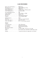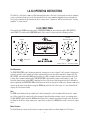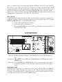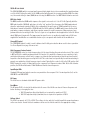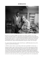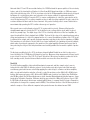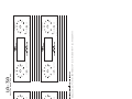
1
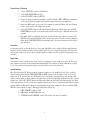
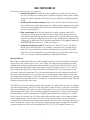
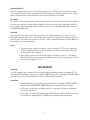
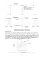
Model LA-3A
AUDIO LEVELER
Universal Audio Manual Number 65-1301
Revision 1.53
IMPORTANT SAFETY INSTRUCTIONS
Before using this unit, be sure to carefully read the applicable items of these operating instructions and the safety
suggestions. Afterwards keep them handy for future reference. Take special care to follow the warnings indicated on the
unit, as well as in the operating instructions.
1.
2.
3.
4.
5.
6.
7.
Water and Moisture - Do not use the unit near any
source of water or in excessively moist environments.
Object and Liquid Entry - Care should be taken so that
objects do not fall, and liquids are not spilled, into the
enclosure through openings.
Ventilation - When installing the unit in a rack or any
other location, be sure there is adequate ventilation.
Improper ventilation will cause overheating, and can
damage the unit.
Heat - The unit should be situated away from heat
sources, or other equipment that produce heat.
Power Sources - The unit should be connected to a
power supply only of the type described in the operating
instructions, or as marked on the unit.
Power Cord Protection - AC power supply cords should
be routed so that they are not likely to be walked on or
pinched by items placed upon or against them. Pay
particular attention to cords at plugs, convenience
receptacles, and the point where they exit from the unit.
Never take hold of the plug or cord if your hand is wet.
Always grasp the plug body when connecting or
disconnecting it.
Grounding of the Plug - This unit is equipped with a 3wire grounding type plug, a plug having a third
(grounding) pin. This plug will only fit into a groundingtype power outlet. This is a safety feature. If you are
unable to insert the plug into the outlet, contact your
electrician to replace your obsolete outlet. Do not defeat
the purpose of the grounding-type plug.
8.
9.
10.
11.
12.
13.
Carts and Stands - The unit should be used only with a
cart or stand that is recommended by the manufacturer.
The unit and cart combination should be moved with
care. Quick stops, excessive force and uneven surfaces
may cause the unit and cart combination to overturn.
Wall Or Ceiling Mount - The unit should be mounted to a
wall or ceiling only as recommended by the
manufacturer.
Cleaning - The unit should be cleaned only as
recommended by the manufacturer.
Nonuse Periods - The AC power supply cord of the unit
should be unplugged from the AC outlet when left
unused for a long period of time.
Damage Requiring Service - The unit should be
serviced by a qualified service personnel when:
• The AC power supply cord or the plug has
been damaged: or
• Objects have fallen or liquid has been spilled
into the unit; or
• The unit has been exposed to rain; or
• The unit does not operate normally or exhibits
a marked change in performance; or
• The unit has been dropped, or the enclosure
damaged.
Servicing - The user should not attempt to service the
unit beyond that described in the operating instructions.
All other servicing should be referred to qualified service
personnel.
Notice
This manual provides general information, preparation for use, installation and operating instructions for the Universal
Audio LA-3A Audio Leveler. The information contained in this manual is subject to change without notice. Universal Audio,
Inc. makes no warranties of any kind with regard to this manual, including, but not limited to, the implied warranties of
merchantability and fitness for a particular purpose. Universal Audio, Inc. shall not be liable for errors contained herein or
direct, indirect, special, incidental, or consequential damages in connection with the furnishing, performance, or use of
this material.
Copyright © 2005 Universal Audio, Inc.
All rights reserved. This manual and associated software, artwork, product designs, and design concepts are subject to
copyright protection. No part of this document may be reproduced, in any form, without prior written permission of
Universal Audio, Inc.
Trademarks
LA-2A, LA-3A, 1176LN, 2-610, 2108, 6176, 2-1176, LA-610, 4110, 8110 and the Universal Audio, Inc. logo are trademarks
of Universal Audio, Inc. Other company and product names mentioned herein are trademarks of their respective companies.
ii
THE LA-3A AUDIO LEVELER
Thank you for purchasing the LA-3A Audio Leveler. The LA-3A is a solid-state version of Universal Audio’s
vacuum tube based Teletronrix LA-2A, and was designed by Brad Plunkett. In it’s day, the LA-3A was considered an improvement over the LA-2A because it eliminated “noisy tubes” and maintenance issues. Today, both
products are revered for their smooth and musical control of audio levels. Engineers choose the LA-2A or LA-3A
based on the different sonic character each one offers.
The T4 Compressor elements in the LA-3A are identical to the circuit components housed inside the T4
optical cell used on the legendary LA-2A compressor. The heart and soul of the LA-3A is mostly a result of this
special optical gain control element. When first developed in the early 1960’s, the electro-luminescent optical
gain reduction was quite revolutionary: applying the audio signal to an electro-luminescent light panel which
shines on a photo-electric cell which in turn controls the gain. In contrast to the electro-optical devices that
preceded it, the electro-luminescent light source provided the fast attack necessary for broadcast applications.
Additionally, the cadmium-sulfide photocells provided a very natural “two-stage” release, which resulted in a
compression characteristic more transparent than the other compressors of the day. The LA-3A features handwired components and two simple front panel controls. Its ease of operation and signature tone make it a first
call for vocals, guitars and just about any application where an ultra fast release time is not needed.
In addition to the LA-3A and Teletronrix LA-2A Leveling Amplifiers, Universal Audio has released reproductions of the classic 1176LN Limiter as well as the 610 tube preamp and 2108 microphone preamplifier. UA
also offers several channel strips and “2 pak” units based on these vintage circuits. In addition, the 4110 and
8110 Precision Microphone preamps deliver ultra high performance clarity utilizing modern capacitor free JFET
circuits. Universal Audio also creates software emulation’s of our vintage hardware that run on our UAD-1 DSP
card as well as Digidesign’s Pro Tools platform. All of these products are designed to meet the demands of the
modern recording studio, yet retain the character of vintage equipment. Please visit www.uaudio.com to see
and read about other great recording tools from Universal Audio.
Once again, thank you for supporting Universal Audio. We hope our products bring inspiration to your musical
endeavors.
Universal Audio, Santa Cruz, California
iii
TABLE OF CONTENTS
LA-3A SPECIFICATIONS
3
LA-3A FRONT PANEL
4
LA-3A REAR CHASSIS
5
STEREO OPERATION
7
WHAT COMPRESSORS DO
9
Peak Reduction. . . . . . . . . . . . . . . . . . . . . . . . . . . . . . . 4
Gain. . . . . . . . . . . . . . . . . . . . . . . . . . . . . . . . . . . . . . . . . 4
Meter Function. . . . . . . . . . . . . . . . . . . . . . . . . . . . . . . . 4
Meter Calibration. . . . . . . . . . . . . . . . . . . . . . . . . . . . . . 5
Limit/Compress Switch. . . . . . . . . . . . . . . . . . . . . . . . . 5
50/30 dB Gain Switch. . . . . . . . . . . . . . . . . . . . . . . . . . . 6
MOD Gain Switch. . . . . . . . . . . . . . . . . . . . . . . . . . . . . . 6
Stereo ADJ Control. . . . . . . . . . . . . . . . . . . . . . . . . . . . . 6
High Frequency Contour Control. . . . . . . . . . . . . . . . . . 6
Input/Output XLRs. . . . . . . . . . . . . . . . . . . . . . . . . . . . . 6
AC Power. . . . . . . . . . . . . . . . . . . . . . . . . . . . . . . . . . . . 6
Fuse/Mains. . . . . . . . . . . . . . . . . . . . . . . . . . . . . . . . . . . 6
Voltage Select. . . . . . . . . . . . . . . . . . . . . . . . . . . . . . . . 6
Unbalanced Connections. . . . . . . . . . . . . . . . . . . . . . . . 7
Balanced Connections. . . . . . . . . . . . . . . . . . . . . . . . . . 7
Chassis Ground. . . . . . . . . . . . . . . . . . . . . . . . . . . . . . . . 7
Rear Chassis Link Connections. . . . . . . . . . . . . . . . . . . 7
Stereo Setup / Calibration. . . . . . . . . . . . . . . . . . . . . . . 8
Stereo Use. . . . . . . . . . . . . . . . . . . . . . . . . . . . . . . . . . . 8
Applications. . . . . . . . . . . . . . . . . . . . . . . . . . . . . . . . . . 8
Control Settings. . . . . . . . . . . . . . . . . . . . . . . . . . . . . . . 8
Attack and Release. . . . . . . . . . . . . . . . . . . . . . . . . . . . 9
Compressing Vocals. . . . . . . . . . . . . . . . . . . . . . . . . . . 10
Bass Guitar. . . . . . . . . . . . . . . . . . . . . . . . . . . . . . . . . . 10
Any Sound. . . . . . . . . . . . . . . . . . . . . . . . . . . . . . . . . . . 10
Tricks. . . . . . . . . . . . . . . . . . . . . . . . . . . . . . . . . . . . . . 10
RACK MOUNTING
Single Unit. . . . . . . . . . . . . . . . . . . . . . . . . . . . . . . . . . 10
Instructions. . . . . . . . . . . . . . . . . . . . . . . . . . . . . . . . . 10
Dual Unit. . . . . . . . . . . . . . . . . . . . . . . . . . . . . . . . . . . . 11
Instructions. . . . . . . . . . . . . . . . . . . . . . . . . . . . . . . . . 11
1
10
COMPRESSOR THEORY OF OPERATION
12
HISTORICAL NOTES
16
RECALL SHEET
19
Compressor Basics. . . . . . . . . . . . . . . . . . . . . . . . . . . 12
The T4 Cell. . . . . . . . . . . . . . . . . . . . . . . . . . . . . . . . . . 14
Side-Chain Circuit. . . . . . . . . . . . . . . . . . . . . . . . . . . . 15
The 610 Preamp. . . . . . . . . . . . . . . . . . . . . . . . . . . . . . 17
Classic Compressors. . . . . . . . . . . . . . . . . . . . . . . . . . 17
The 1176 LN. . . . . . . . . . . . . . . . . . . . . . . . . . . . . . . . . 17
The LA-2A. . . . . . . . . . . . . . . . . . . . . . . . . . . . . . . . . . . 18
2
LA-3A SPECIFICATIONS
Balanced Line Input Impedance. . . . . . . .
Max. Input Level. . . . . . . . . . . . . . . . . . . .
Internal Output Impedance. . . . . . . . . . . .
Maximum Output Level. . . . . . . . . . . . . . .
Internal Output Impedance. . . . . . . . . . . .
Recommended Minimum Load. . . . . . . . .
Frequency Response. . . . . . . . . . . . . . . . .
Maximum Gain. . . . . . . . . . . . . . . . . . . . .
Noise Floor. . . . . . . . . . . . . . . . . . . . . . . . .
Distortion. . . . . . . . . . . . . . . . . . . . . . . . .
Max Gain Reduction. . . . . . . . . . . . . . . . .
Attack Time. . . . . . . . . . . . . . . . . . . . . . . .
Release Time (stage 1). . . . . . . . . . . . . . .
Release Time (stage 2). . . . . . . . . . . . . . .
General
Power Requirements. . . . . . . . . . . . . . . . .
Fuse (115V use). . . . . . . . . . . . . . . . . . . .
Fuse (230V use). . . . . . . . . . . . . . . . . . . .
Max. Power Consumption. . . . . . . . . . . . .
Dimensions. . . . . . . . . . . . . . . . . . . . . . . .
Weight. . . . . . . . . . . . . . . . . . . . . . . . . . . .
Warranty. . . . . . . . . . . . . . . . . . . . . . . . . .
600Ω floating
-0dBm @ 50dBm gain setting
600Ω floating
+20 dBm nominal, 27 dBm max. peaks
approximately 50Ω
50Ω
20 Hz to 20 kHz +/- 0.5dB
50 dB +/- 1 dB
-80 dB @ limiting threshold
< 0.35% THD @ +24 dBm
40 dB
1.5ms or less, program dependent
60 ms (50% release)
0.5 to 5 seconds, program dependent
115V / 230V operation
3AG 1/8amp TD (slow blow)
3AG 1/16 amp TD (slow blow)
35 Watts
3.5” vertical (2RU), 1/2 19” rack, 9.25” depth
6.5 lbs. (boxed, 11 lbs.) Dual LA-3A, 13.0 lbs. (boxed 19 lbs)
1 year, parts and labor (go to www.uaudio.com for details)
3
LA-3A OPERATING INSTRUCTIONS
The LA-3A is a solid state compressor that automatically reduces the level of loud signals in order to maintain
a more consistent volume level, void of loud peaks that can cause unwanted clipping and associated distortion. For the remainder of this manual, the more common term “compressor” will be used instead of “leveling
amplifier” or “audio leveler”.
LA-3A FRONT PANEL
This panel has the GAIN knob, analog meter, PEAK REDUCTION knob, meter function switch (GR / OUTPUT),
meter ZERO SET control and the POWER ON switch. Each control is discussed in the following sections.
PEAK
REDUCTION
GAIN
��
�� �� �� � �� �� ��
��� ��� ��
��
� �� �� �� �� ���
GR
OUTPUT
POWER
UNIVERSAL AUDIO, INC.
ON
SANTA CRUZ, CALIFORNIA
Peak Reduction
The PEAK REDUCTION control determines when the compressor receives a signal “loud” enough to trigger gain
reduction as well as total output level. Higher settings will increase the relative amount of compression. The
GR / OUTPUT switch below the GAIN knob should be set to GR to view the amount of gain reduction the LA-3A
is doing. We recommend adjusting the PEAK REDUCTION control until the meter reads between -3 and -5 on
the meter during volume peaks. NOTE: adjusting the level of the device that’s plugged into the LA-3A input as
well as adjusting the PEAK REDUCTION control knob can affect the amount of compression. Heavily compressed
signals can be made louder by increasing the GAIN knob just to the left of the meter. See “Side Chain Circuit”
on page 14 for technical details.
Gain
The GAIN control behaves like an output level control. Turning this control clockwise will increase the output
level of the signal at the output jack on the rear panel, typically feeding a mixing console or recording device.
The GR / OUTPUT switch below the GAIN knob should be set to output to view signal strength on the LA-3A meter. When the LA-3A is in deep compression, signal level is reduced. The GAIN knob is used to restore the signal
level.
Meter Function
The LA-3A VU meter can be used to indicate compressor gain reduction or final output level. The meter
4
function is determined using the two-position switch below the GAIN knob to the left of the meter. When OUTPUT is selected, a meter reading of 0 corresponds to an output level of +4 dBm at the LA-3A output. In the GR
mode the meter will move from 0 to negative numbers on the left side. The meter will indicate relative levels of
gain reduction during loud signal passages. Typically, the PEAK REDUCTION control is adjusted to read between -3 and -5 on the meter. However, turning the PEAK REDUCTION knob to higher numbers will yield an even
greater magnitude of gain reduction, such as -10 or more. Trust your ears!
Meter Calibration
The 0dB gain reduction reading may need to be calibrated using the GR zero set pot and a very small slotted
screwdriver. The GR zero set pot is located through a small hole on the front panel just above the P of the word
POWER by the POWER ON switch. See front panel drawing on page 3.
1. Turn the LA-3A on and warm up for 5 minutes.
2. Set the meter switch to the GR position.
3. With the PEAK REDUCTION control full off (CCW) adjust the GR zero set trim pot so the meter
reads 0 dB. Turn pot slowly.
LA-3A REAR CHASSIS
MODEL
SERIAL
�����
�����
��
��
On the left: AC Power transformer, FUSE holder, 115V / 230V switch and standard IEC AC power receptacle.
In the middle: LIMIT / COMPRESS switch, MOD switch, 50/30dB GAIN switch, STEREO ADJ control and HF
CONTOUR control.
On the right: the LA-3A LINE INPUT, and LINE OUTPUT XLR connectors and terminal strip screw connectors
for hard-wired installations. These controls and connectors are discussed in the following
section.
Limit/Compress Switch
The Limit/Compress Switch changes the characteristics of the compressor I/O curve. When in the COMPRESS
position, the curve is gentler, and presents a low compression ratio. A higher compression ratio results when
the switch is set to the LIMIT position. The difference in these two modes is only present when the LA-3A is in
deep compression. Most users leave the LA-3A in COMPRESS mode.
5
50/30 dB Gain Switch
The 50/30 dB GAIN switch is an input pad to prevent high output devices from overdriving the input transformer of the LA-3A. Setting the switch to the 30dB position will attenuate the incoming signal by 20dB. For studio
use, the normal setting is down (30dB) when not using the MOD function. See MOD Switch below for more info.
MOD Gain Switch
The MOD (modification) GAIN switch improves the signal to noise ratio of a “stock” LA-3A. Typically, both the
MOD switch and the 50/30 dB switch are set in the “up” position. This disengages the 20dB input pad and
drops the output amp’s gain by 24 dB. In this configuration, the unit’s gain is +26dB and will be less noisy
than when in normal mode with the 50/30 dB switch at 30. In addition, the MOD switch lowers the threshold
point where compression begins and allows a greater amount of overall compression. Many engineers have
performed this mod on vintage LA-3As. The loss of gain is not a problem in most applications as the LA-3A has
about 50dB gain to begin with. The improvement in signal to noise is usually a desirable trade off. We have
supplied this modification as a switchable feature so you can operate with or with out the modification.
Stereo ADJ Control
The STEREO ADJ (adjust) control is used to balance two LA-3As gain reduction when used for stereo operation.
See Stereo Operation on page 6 for more info.
High Frequency Contour Control
The HF CONTOUR control is a high frequency boost of the signal feeding the gain reduction circuit. This control
is NOT an EQ of the audible program material. It’s function is to make the compressor more sensitive to high
and high mid frequency content and to compress or attenuate that spectrum more than the mid and low end
frequencies that are being processed by the LA-3A. This control was used specifically for radio broadcasting to
prevent over modulation of high frequency signal content. Typically, this control is left in the FLAT position (full
CCW). Turning the control clockwise will increase compression of frequencies above 1kHz. At the full clockwise
position, the LA-3A will attenuate 15kHz 10dB more than the lower frequencies.
Input/Output XLRs
Standard XLR input and output connectors are provided on the rear panel. Pin 2 is wired positive (hot) on the
LINE INPUT and LINE OUTPUT.
AC Power
The LA-3A uses a standard detachable IEC power cable.
Fuse/Mains
The AC power FUSE is located at the bottom far left corner of the LA-3A rear chassis. Remove the power cord
before checking or changing the fuse.
• 3AG 1/8 amp time delay (slow blow) fuse is required for operation at115 V.
• 3AG 1/16 amp time delay (slow blow) fuse is required for operation at 230 V.
Voltage Select
The LA-3A can operate at 115 V or 230 V. The voltage selector switch is located beneath the power transformer
on the rear chassis. A small slotted screwdriver can be used to slide the switch to the appropriate setting.
6
• When changing operating voltage, the fuse value must be changed as well.
• Make sure the LA-3A is properly set for the voltage in your area before applying AC power to unit!
Input/Output Terminal Strip
The terminal strip provides screw connections for INPUT, OUTPUT, STEREO balance and CHASSIS GROUND.
The strip can be used instead of the XLR connections. In addition, you can use the XLR OUTPUT as well as the
terminal strip output to “split” the output signal and feed two separate devices. The terminal strip is the only
means to connect two LA-2As for stereo operation. See Stereo Operation on the next page for more info. NOTE:
The 600 ohm resistor across screws 5 & 6 must not be removed for proper operation of the output terminals
AND the Output XLR jack.
�
�����
�
�������
�
������
�
�
������
�
Unbalanced Connections
Connect the “hot” cable lead (usually pin 2 of XLR cable) to the +/- terminal. Connect the “shield braid” to the
COM terminal.
Balanced Connections
Connect the “hot” cable lead (usually pin 2 of XLR cable) to the +/- terminal. Connect the “neutral” lead (usually pin 3 of XLR cable) to the COM terminal.
Chassis Ground
Connect the ground or “shield braid” (usually pin 1 of XLR cable) of the LA-3A output only. However, you may
not want to connect this wire if it causes hum noise in the audio signal. You may need to connect the input
cable ground wire as well if it eliminates hum problems.
STEREO OPERATION
Rear Chassis Link Connections
Connect a shielded cable to the CHASSIS and STEREO pins on the rear panel of one LA-3A. Connect the shield
wire to the CHASSIS (3) terminal and the “hot” or center lead to the STEREO (4) terminal. Connect the other end
of this cable to the second LA-3A in the same fashion
7
Stereo Setup / Calibration
1. Set the STEREO ADJ control to full Clockwise.
2. Set the PEAK REDUCTION knob to 0.
3. Set the GR / OUTPUT switch to OUTPUT.
4. Connect a signal generator to the inputs of both LA-3A units. 400 to 1000 Hz recommended.
Set the signal generator output level to produce a typical level for your application.
5. Adjust the GAIN control on each unit so the outputs are equal at O dB on each unit. External
meters can be used to view output level as well.
6. Set the GR / OUTPUT switch to GR (Gain Reduction Metering) on both units. Turn the PEAK
REDUCTION knob on just one of the two units until the meter reads -5 dB; both units should
respond.
7. Note which LA-3A is reading the most gain reduction. On this unit, turn the rear panel STEREO ADJ control until both LA-3A meters read the same value. The unit is now in calibration.
Bring up the PEAK REDUCTION of the remaining unit to the same numerical value to match
gain reduction.
Stereo Use
You are now ready to use the two units as a stereo pair. Typically the users adjusts both front panel knobs in
tandem to achieve matched compression and output levels. The stereo image should remain solid and both
units should compress the stereo signal equally, regardless of which side (left or right) is triggering the gain
reduction.
Applications
This manual section is for those who haven’t had a lot of experience using compressors. If the LA-3A is your
first compressor, then this section may be particularly helpful. The Compressor Theory of Operation (on page
11) is a more technical overview of compressors and how the electronic circuits work.
Control Settings
One of the reasons the LA-3A has remained a popular compressor is its simplicity of use. There is nothing
critical to adjust other than the PEAK REDUCTION and GAIN controls on the front panel. First set these two
knobs at their “0” position. Once the LA-3A input jack is connected to your input device (mic preamp, synth
output, console output, recorder output, or any other line level device) simply turn the Gain knob up to a desired
volume level. Put the GR / OUTPUT knob in the GR position. Now turn the Peak Control knob up until the LA-3A
meter reads between -3 and -5 on the meter during volume peaks. Feel free to experiment with lighter or higher
settings. Adjust the Gain knob to bring the signal up when using heavy compression. Please review the REAR
CHASSIS control settings on page 3. Our suggested default settings are:
1. LIMIT / COMPRESS switch “down”
2. MOD switch and 30/50 dB switch “up”
3. STEREO ADJ and HF CONTOUR controls full counter clock wise (as shipped)
8
WHAT COMPRESSORS DO
There are four main reasons to use a compressor:
1. Prevent loud transients or volume bursts from overdriving a recording device or sound system. These loud burst can completely destroy a digital recording by creating terrible sounding
distortion. Constant overdriving of a PA system can cause subtle, but ear fatiguing distortion
as well.
2. Smooth out wide variations in volume creating a more controlled sound. Useful when recording a vocalist who has a wide dynamic range or to condition a pad or supporting musical part
(such as an acoustic rhythm guitar). Also useful for instrumentalists (such as horn players)
who move on and off the mic.
3. Make a sound louder. When the loudest peaks of a recording are turned down, then the
entire track can be turned up. This makes the softer sections and the average volume level
louder than they were before the signal was compressed. This is often the main reason many
engineers use compressors. When this is the goal, it’s often desirable for the compressor to be
“transparent” or unnoticeable. The LA-3A works particularly well for this application when the
PEAK REDUCTION meter shows -3 to -5 dB of gain reduction.
4. Change the character of a sound. All sounds have an “attack” and “decay”. The attack is
what we hear in the first fraction of a second when a snare drum is hit or a guitar string is
plucked. The decay is what we hear after the attack when the tone or pitch of a note fades
away. The decay can be fairly quick, such as the fading ring of a snare drum or quite long as
in the case of a piano chord being held while the sustain pedal held down.
Attack and Release
Most compressors have attack and release controls that will change the sound of an instruments attack and
decay (release). If the attack control is set to a “fast” setting, the compressor will instantly turn the signal
down which will attenuate the high frequency transients that are present in the initial attack. This is a good
way to warm up an overly bright or edgy acoustic guitar recording. If the attack control is set to a “slow” setting, the natural full volume of the sounds attack will be heard and then the “slow acting compressor” will
get around to turning the volume down. This is often done when you want to hear the bright clean attack of a
percussion sound or the attack of an acoustic bass. Also, vocals often want a medium attack, as they sound
more natural with the full harmonic content of the articulation. If an attack is set too slow, then the compressor
will not attenuate loud attack transients. So, sometimes it’s a compromise between getting the right sound and
getting the desired amount of gain control.
The LA-3A does not have user controls for attack and release times. It’s attack and release times are automatically controlled by the nature of the T4 Cell used in the LA-3A’s circuitry. The lack of controls has some benefits
and some disadvantages. On the plus side, the LA-3A will change the speed of it’s attack and release automatically depending on the nature of the sound and the magnitude of compression. For instance, the release time
will be quick with occasional light compression (-3db) but slower if driven hard continuously (-7 to -10 dB).
Also, the release time has two stages. It releases quickly at first and then slower. See the Compression Basics
section starting on page 11 for more details. The lack of controls also prevents the user from setting them
incorrectly. Due to the automatic and extremely musical way the LA-3 rides level, it’s quick and easy to get good
results. The down side: sometimes you need a quicker release time or you want to manipulate the attack time
as mentioned previously. In this case the Universal Audio 1176, 2-1176 or 6176 may be the perfect tool.
9
Compressing Vocals
The LA-3A is very popular for vocals. First of all, like many pieces of “vintage” gear the LA-3A has a unique
“sonic signature” produced by the audio path transformers and discrete amplifier components. This, coupled
with the attack and release character, produces great results that bring vocals forward.
Bass Guitar
The LA-3A is also very popular for Bass. Again, the preset nature of the attack and release functions work well
for letting some transients through and then shaping the release in a smooth way. Coupled with the LA-3As
sonic signature, extremely desirable results can be achieved. Feel free to experiment with different setting of
the PEAK REDUCTION control.
Any Sound
In general, the LA-3A is very versatile and can be used on any sound, instrument, voice, choir, speech, etc.
when light to medium compression is called for. When driven hard (-10 or greater) the LA-3A may not be the
proper choice for fast tempo music and quick “staccato” sounds if natural transparency is desired. Often it is
just a matter of choice, so experiment!
Tricks
• Try connecting two compressors together in series. Try using an 1176 (or other compressor)
set for fast attack and release in front of an LA-3A. Try it the other way around, with the LA3A going into the other compressor.
• Split a signal, send one to the LA-3A and compress it medium to deep (-5 to -10), mix this
with the natural un-compressed signal. Try different levels of the mix, try using just a little of
the compressed signal or a lot of it.
RACK MOUNTING
Single Unit
The LA-3A shipping carton contains all the necessary brackets and hardware required for standard 19” rack
mount. Bracket and hardware locations are shown below. NOTE: The large half rack faceplate (45-0094) may be
mounted on either side if desired. All that’s needed is a medium Phillips screwdriver.
Instructions
• Attach both brackets to the LA-3A as shown below. Be sure to install the SPACER (45-0091)
with the large half RACK PANEL. DO NOT tighten the screws until all four are in place.
• Set the unit on a flat surface and tighten up all the screws while checking the alignment of
the rack ear and panels.
• In the event a second LA-3A is purchased, the LA-3A dual unit mounting kit will be necessary.
This includes two strapping plates (45-0093) and is available trough any UA dealer.
10
Dual Unit
The LA-3A shipping carton contains all the necessary brackets and hardware required for standard 19” rack
mount. Bracket and hardware locations are shown below
Instructions
1. Set the two LA-3As next to each other as pictured. Remove the 4 screws on the top cover on
the left unit (as shown in the FRONT VIEW drawing below).
2. Remove the 4 screws on the top cover on the right unit (as shown in the FRONT VIEW drawing
below).
3. Attach one of the STRAPPING PLATES to the left unit using the 4 screws that were removed
from the top cover. DO NOT tighten the screws yet!
4. Slip the second LA-3A under the STRAPPING PLATE on the left LA-3A. Connect the two LA-3As
together by re-inserting the 4 screws that were removed from the second unit top cover.
5. Tighten up all screws while checking the alignment of the Units. DO NOT cinch too tight!
6. Carefully flip the units over on to their tops. Repeat the same process to attach the second
STRAPPING PLATE to the bottom of the LA-3As.
7. Attach both RACK EARS to the LA-3As as shown below. DO NOT tighten the screws until all
four are in place. Set the units on a flat surface and tighten all the screws while checking the
alignment of the ears.
11
COMPRESSOR THEORY OF OPERATION
Compressor Basics
Before we dig in to a description of the compressor circuit, it is useful to examine the general characteristics of
compressors and review some terminology. The chart below depicts the input/output characteristics of a compressor, an expander and a perfect amplifier. When operated within its specified range, an amplifier provides a
constant amount of gain regardless of the level of the input signal. In figure 4 below, the middle line depicts a
perfect amplifier with a gain of 10 dB. To see this, notice that a signal with an input level of -30 dB will result
in an output level of -20 dB, which is an increase of 10 dB. Similarly, an input level of 0 dB will result in an
output level of 10 dB, hence the gain stays fixed at 10 dB regardless of the input level.
I N P U T / O U T P U T C H A R A C T E R I S T I C S OF A COMPRESSOR, AN EXPANDER AND A PERFECT AMPLIFIER.
12
In contrast to an amplifier, whose job is to present a constant gain, a compressor varies its gain in response to
the level of the input signal. Large input signals result in less gain, thus reducing or “compressing” the dynamic range of the signal. Referring again to the line marked “compression” in Figure 4, we see that an input
level of -30 dB results in an output level of -20 dB, indicating a gain of 10 dB. Repeating this for input levels
of -20 dB and -10 dB, we see that the compressor exhibits gains of 5 dB and 0 dB respectively. From this, it is
clear that the gain decreases as the input signal increases.
Referring to the diagram, we see that the compressor will increase its output level by 5 dB for every 10 dB that
we increase the input level. The compression ratio is defined as the ratio of these two numbers. In this case
the compression ratio would be 10:5, which can be reduced to 2:1.
As an aside, an expander is a device that increases the dynamic range of a signal. For example, a 10dB
change in the input signal might result in a 20 dB change in the output signal, thus “expanding” the dynamic
range.
As mentioned previously, the compression ratio is defined as the ratio of the increase of the level of the input
signal to the increase in the level of the output signal. In this example, the input level is increased by 10 dB
while the output level only increases 5 dB. This would be a compression ratio of 2:1. Lower ratios such as 2:1
result in more gentle compression. (Note that a compression ratio of 1:1 is no compression at all).
Typically, compressors let you choose a threshold. This is the point at which gain reduction starts to take
place. When an audio signal is below this threshold the compressor acts like an amplifier and there is no gain
reduction. Above the threshold the slope becomes less than 45 degrees, indicating gain reduction and hence
compression.
The point at which a compressor transitions into compression is commonly called the knee. In practical compressors, this transition is gentler than what is depicted in the diagram.
Many modern compressors provide a control that adjusts the threshold directly. In the case of the LA-3A, the
Peak Reduction knob controls both the threshold and the amount of compression.
I N P U T / O U T P U T C U RV E O F A C O M P RESSOR WITH A RATIO OF 2:1 AND A THRESHOLD OF -20 DB.
13
The T4 Cell
D I A G R A M OF THE T4 ELECTRO-OPTICAL CELL
The cell T4 is comprised of an electro-luminescent (EL) panel and a photoelectric cell housed in a light proof
box or can. The EL panel is essentially a night-light. As you would expect, the larger the signal that is applied
to it, the brighter the light that is generated. This light shines upon the photoelectric cell. A photoelectric
cell is a light sensitive device whose resistance changes depending upon the intensity of light to which it is
subjected; the brighter the light, the less resistance the photocell will have.
The photocell is used to control the gain of the circuit. Essentially, the photocell acts as the bottom leg in a
voltage divider circuit. The lower the resistance of the photocell, the lower the signal voltage will be at the output of the gain reduction stage. To see why this is true, we can look at the extreme cases. If the resistance is
extremely high (this is the case when there is a small input signal and the light is off) then the photocell does
not affect the circuit and there is no gain reduction. The second case we can look at is when there is a large
signal present. In this condition, the light shines brightly and the photocell exhibits very low resistance. If the
resistance of the photocell becomes zero (a dead short), then the signal would be grounded and there would be
no output. In reality, the photocell resistance cannot go completely to zero and hence there will always be some
signal present.
The T4 electro-optical device is the heart of the compressor and its gain reduction characteristics. Its unique
characteristics affect the overall sound and character of the LA-3A.
In addition to the compression curve, the combination of the EL panel and the photocell determine the attack
and release characteristics of the LA-3A. This is one of the most important contributors to the sound of the
LA-3A. Unlike other compressors that allow the user to adjust these parameters, the attack and release of the
LA-3A are completely determined by the T4.
There are several important characteristics of the T4 that play crucial roles in the sound of the LA-3A. The first
is the attack. The LA-2A was the first electro-optical compressor to use an electro-luminescent panel for the
light source. Previous attempts at electro-optical compression employed either neon or incandescent lights.
Both of these took time to light up, and this delay resulted in slow attacks. The electro-luminescent panel
resulted in a faster attack than exhibited by other contemporary devices.
The next important aspect is that of the release of the compressor. This is determined almost entirely by the
characteristics of the photocell. The LA-3A the uses the same cadmium-sulfide photocells. The first important
aspect of the cell is its “two-stage decay”. After the light is removed from the cell, it releases quickly (40-80
14
milliseconds) to approximately half of its off resistance. The remainder of its release can take place over as
much as several seconds.
The next aspect is the “memory” of the cell. This results in two important aspects of the character of the LA3A. The amount of time it takes for the cell to recover after the light is removed depends on how long light had
been shining on it and how bright the light. In the case of the LA-3A this results in behavior where the release
time is slower if the unit has either been in compression for a while, or the amount of compression is large.
This signal dependent release characteristic is critical to the sound of the unit.
Side-Chain Circuit
The amount of compression, as well as the compression threshold, is controlled by the “Peak Reduction”
potentiometer. This potentiometer controls the gain of the side-chain circuit. The greater the gain of this
circuit, the lower the threshold and the greater the amount of compression will be. The term side chain comes
from the process of “splitting” the audio into a side path to be used for sensing and controlling loud volume
peaks. The LA-3A is a feedback style compressor. This is due to the fact that the signal that is used to drive
the side-chain circuit is affected by the gain-reduced signal. This signal is first fed into the side-chain drive
circuit and in turn controls the compression threshold and amount of gain reduction. A pre-emphasis circuit is
provided on the output of the side chain amplifier circuit. Originally designed for broadcast, the LA-3A allowed
for side-chain equalization, which allowed the operator to make the compression more or less sensitive to the
voice frequency bands. For musical applications, this equalization is usually set to a flat frequency response.
15
HISTORICAL NOTES
N AT “ K I NG” COLE WITH BILL PUTNAM SR.
Bill Putnam Sr. was awarded the 2000 Technical Grammy for his multiple contributions to the recording
industry. He was highly regarded as a recording engineer, studio designer/operator and inventor. Putnam was
considered a favorite of musical icons including Frank Sinatra, Nat King Cole, Ray Charles, Duke Ellington, Ella
Fitzgerald and many, many more. The studios he designed and operated were known for their sound and were
an experimentation ground for his continuing desire to push the envelope. Universal Recording in Chicago,
United and Western in Los Angeles (now Ocean Way and Cello) all preserve elements of his room designs.
The companies Putnam started, Universal Audio, Studio Electronics, and UREI, built products that are still in
regular use decades after their development.
In 1999 Bill Jr. and James Putnam re-launched Universal Audio and merged with Kind of Loud technologies - a
leading audio software company - with two goals: Reproduce classic analog recording equipment designed by
their father and his colleagues, research and design new recording tools in the spirit of vintage analog technology. Today Universal Audio is fulfilling that goal, bridging the worlds of vintage analog and DSP technology in a
creative atmosphere where musicians, audio engineers, analog designers and DSP engineers intermingle and
exchange ideas every day. Analog or digital, UA remains committed to the “hand assembled” ideal that has been
forgotten by many audio manufacturers. Whatever the endeavor, every project taken on by the UA team is driven by
its historical roots and a desire to wed classic analog technology with the demands of the modern digital studio.
16
The 610 Preamp
The 2-610 was inspired by the Putnam-designed 610 console built in 1960 for his United Recording facility at
6050 Sunset Boulevard in Hollywood (now Ocean Way). As was the case with most of Putnam’s innovations, the
610 was the pragmatic upshot of a recurring problem in the studio: how to fix a console without interrupting a
session. The traditional console of the time was a one-piece control surface with all components connected via
patch cords. If a problem occurred, the session came to a halt while the console was dismantled. Putnam’s
solution was to build a mic-pre with gain control, echo send and adjustable EQ on one modular chassis using a
printed circuit board. While modular consoles are commonplace today, the 610 was quite a breakthrough at the
time.
While the 610 was designed for practical reasons, it was aesthetic appeal that made it popular with the recording artists who frequented United and Western in the 60’s. The character of the mic-pre in particular made
it favorite of engineers like Bruce Swedien, Bruce Botnick, Lee Hershberg and Jack Joseph Puig; and artists
including Sarah Vaughan, Frank Sinatra, Ray Charles, and The Beach Boys. Swedien describes the character of
the preamp as “clear and open” and “very musical”. Studios 2 and 3 at Western, which featured the 610 console, were the site of many classic recordings of the 60’s, including the Mamas and the Papas (Bones Howe),
Up, Up and Away by the Fifth Dimension, Herb Alpert, Sergio Mendes (Bruce Botnick), and of course Pet Sounds.
Legendary engineer Wally Heider, manager of remote recording at United, used his 610 console to record many
live recordings including Peter, Paul and Mary “In Concert” (1964), Wes Montgomery’s “Full House” (1962), and
all of the Smothers Brothers Live albums. Heider’s console was later acquired by Paul McManus in 1987, and
spent a decade restoring it. [We thank Paul for his efforts and his contribution to our efforts to trace the history
of the 610.]
At least one 610 module is still in use at Ocean Way. Allen Sides, who purchased the studio from Putnam to
open Ocean Way, personally traveled to Hawaii to collect the 610 console that was used to record the live “Hawaii Calls” broadcasts. Jack Joseph Puig has been ensconced in Studio A with the 610 (and a stunning collection of vintage gear) where he has applied the vintage touch to acts including Beck, Hole, Counting Crows, Goo
Goo Dolls, No Doubt, Green Day and Jellyfish.
Classic Compressors
The LA-2A and 1176 compressor/limiters long ago achieved classic status. They’re a given in almost any studio
in the world - relied upon daily by engineers whose styles range from rock to rap, classical to country and
everything in between. With so many newer products on the market to choose from, it’s worth looking at the
reasons why these classics remain a necessary part of any professional studio’s outboard equipment collection.
The basic concept of a compressor/limiter is of course, relatively simple. It’s a device in which the gain of a
circuit is automatically adjusted using a predetermined ratio that acts in response to the input signal level. A
compressor/limiter “rides gain” like a recording engineer does by hand with the fader of a console: it keeps the
volume up during softer sections and brings it down when the signal gets louder. The dynamic processing that
occurs at ratios below 10 or 12 to one is generally referred to as compression; above that it’s known as limiting. Modern day compressors offer a great degree of programmability and flexibility while older devices such as
the 1176 and the LA-2A are more straightforward in their design. Perhaps it is this fact that has contributed to
their appealing sound and the longevity of their popularity.
The 1176LN
The original Universal Audio 1176LN was a major breakthrough in limiter technology - the first true peak limiter
with all transistor circuitry offering superior performance and a signature sound. Evolved from the popular
17
Universal Audio 175 and 176 vacuum tube limiters, the 1176LN retained the proven qualities of these industry
leaders, and set the standard for all limiters to follow. It was Bill Putnam himself who, in 1966, was responsible for the initial design of the 1176. Its circuit was rooted in the 1108 preamplifier, which was also designed
by Putnam. As is evident from entries and schematics in his design notebook, he experimented with the
recently developed Field Effect Transistor (F.E.T.) in various configurations to control the gain reduction in the
circuit. He began using F.E.T.s as voltage variable resistors, in which a voltage applied to the gate controls the
resistance between the drain and the source terminals. His greatest challenge was to ensure that distortion
was minimized by operating the F.E.T.s within a linear region of operation.
After several unsuccessful attempts at using F.E.T.s in gain reduction circuits, Putnam settled upon the
straightforward approach of using the F.E.T. as the bottom leg in a voltage divider circuit, which is placed
ahead of a preamp stage. The output stage of the 1176 is a carefully crafted class A line level amplifier, designed to work with the (then) standard load of 600Ω. The heart of this stage is the output transformer, whose
design and performance is critical. Its primary function is to convert the unbalanced nature of the 1176 circuit
to a balanced line output, and to provide the proper impedance matching to drive the line impedance of 600Ω.
This transformer is critical due to the fact that it uses several additional sets of windings to provide feedback,
which makes it an integral component in the operation of the output amplifier. Putnam spent a great deal of
time perfecting the design of this tricky transformer and carefully qualified the few vendors capable of producing it.
The first major modification to the 1176 circuit was designed by Brad Plunkett in an effort to reduce noise-hence the birth of the 1176LN, whose LN stands for low noise. Numerous design improvements followed, resulting in at least 13 revisions of the 1176. The D and E ‘black-face’ LN revisions are widely considered to be the
best-sounding models; therefore Universal Audio modeled our reissue after these two models.
The LA-2A
The LA-2A leveling amplifier, a tube unit with hand wired components and three simple controls, was introduced in the early 1960s. It utilized a system of electro-luminescent optical gain control that was quite
revolutionary; gain reduction was controlled by applying the audio voltage to a luminescent driver amplifier,
with a second matched photoconductive cell used to control the metering section. With its 0 to 40 dB of gain
limiting, flat frequency response of 0.1 dB from 30-15,000 Hz and a low noise level (better than 70 dB below
plus 10 dBm output,) the LA-2A quickly became a studio standard. Originally patented by Jim Lawrence, it was
produced by Teletronix in Pasadena, California, which became a division of Babcock Electronics Corp. in 1965.
In 1967 Babcock’s broadcast division was acquired by Bill Putnam ‘s company, Studio Electronics Corporation
shortly before he changed the company’s name to UREI(r). Three different versions of the LA-2A were produced
under the auspices of these different companies before production was discontinued around 1969.
18
GR
GR
GAIN
GAIN
SANTA CRUZ, CALIFORNIA
ON
UNIVERSAL AUDIO, INC.
POWER
SANTA CRUZ, CALIFORNIA
ON
PEAK
REDUCTION
UNIVERSAL AUDIO, INC.
POWER
GR
GR
GAIN
GAIN
OUTPUT
OUTPUT
SANTA CRUZ, CALIFORNIA
UNIVERSAL AUDIO, INC.
POWER
SANTA CRUZ, CALIFORNIA
ON
PEAK
REDUCTION
UNIVERSAL AUDIO, INC.
ON
PEAK
REDUCTION
POWER
330 Encinal Street • Santa Cruz CA • 95060-2101 • www.uaudio.com • toll-free: 866-UAD-1176 • voice: 831-466-3737 • fax: 831-466-3775
OUTPUT
OUTPUT
PEAK
REDUCTION
Session Recall Sheet
LA-3A