1
IFM500(영문) 1904.2.3 9:48 PM 페이지1
001 pdf-in
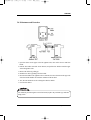
Head Office/Factory
687-5, Sangoan-ri, Hongcheon-eub, Hongcheon-gun,
Gangwon-do, Korea (zip.250-804)
Tel : +82-33-434-9041 Fax : +82-33-434-9043
Seoul Office/R&D
3F, Kwangsung Venture Plaza, 445, Daehung-dong, Mapo-gu,
Seoul, Korea, 121-080, Republic of korea
Tel : +82-2-714-2962 Fax : +82-2-714-2963
Customer Service Dept.
Tel : +82-2-714-2962 Fax : +82-2-714-2963
IFM500(영문) 1904.2.3 9:48 PM 페이지2
001 pdf-in
Operation Manual
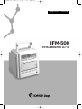
IFM-500
FETAL MONITOR Ver 1.4
IFM500(영문) 1904.2.3 9:48 PM 페이지3
001 pdf-in
IFM500(영문) 1904.2.3 9:48 PM 페이지4
001 pdf-in
Table of Contents
1. INTRODUCTION
2. SAFETY PRECAUTIONS
2.1 Proper Environment for the use of IFM-500
2.2 Electrical Safety precaution
2.3 Maintenance and protection
2.4 Fuse Replacement
3. SPECIFICATIONS
3.1 Standard Specification
4. PRODUCT DESCRIPTION
4.1 Composition of IFM-500
4.2 Name of Each part
5. INSTALLATION
5.1 Transducer and Evevnt maker Connection
5.2 Recordfing paper Installation
5.3 Power Connection
6. SET-UP MODE
6.1 Initial Set-UP
6.2 Set-up Function
7. OPERATION
3
4
4
6
8
9
10
10
12
12
13
17
17
18
18
19
19
20
26
7.1 Control panel
26
7.2 FHR(Fetal Heart Rate)
28
7.3 UC(Uterine Contraction)
29
7.4 Alarming
29
7.5 Recording
29
7.6 Evevnt Marking
30
7.7 Self-test(Calibration)operation
30
8. HOW TO USE TRANSDUCERS
31
8.1 Doppler measurement method
31
8.2 UC measurement method
33
9. ERROR MESSAGE AND COUNTERMESURE
34
10. RECORDING PAPER
35
A. AFTER SERVICE
37
B. WARRANTY
39
IFM500(영문) 1904.2.3 9:48 PM 페이지5
001 pdf-in
IFM500(영문) 1904.2.3 9:48 PM 페이지1
001 pdf-in
IFM-500
Preface
Notes To Users
■ Thank you for purchasing the IFM-500 Fetal Monitor. To ensure safe operation and long term
performance stability, it is essential that you fully understand the functions, operating and
maintenance instructions by reading this manual before operating equipment.
■ Particular attention must be paid to all warnings, cautions, and notes incorporated herein.
● Incorrect operation, or failure of the user to maintain the equipment relieves the
manufacturer or his agent of the system’s noncompliance with specifications or of
responsibility for any damage or injury.
●
The following conventions are used throughout the manual to denote information of special
emphasis.
“Warning” is used to indicate the presence of a hazard which can cause severe personal
injury, death, or substantial property damage if the warning is ignored.
“Caution” is used to indicate the presence of a hazard which will or can cause minor personal
injury property damage if the caution is ignored.
“Note” is used to notify the user of installation, operation, or maintenance information which
is important but not hazard related.
Notes To Users 1
IFM500(영문) 1904.2.3 9:48 PM 페이지2
001 pdf-in
FETAL MONITOR
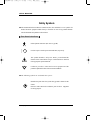
Safety Symbols
■ The International Electrotechnical Commission (IEC) has established a set of symbols for
medical electronic equipment which classify a connection or warn of any potential hazards.
The classifications and symbols are shown below.
Save these instructions.
Isolated patient connection. (IEC 601-1-Type BF)
I and O on power switch represent ON and OFF, respectively.
This symbol identifies a safety note. Ensure you understand the
function of this control before using it. Control function is described
in the appropriate operation manual.
Conductor provides a connection between equipment and the
potential equalization busbar of the electrical installation.
■ The following symbols are used inside the system :
Identifies the point where the system safety ground is fastened to the
chassis.
Protective earth connected to conductive parts of Class I equipment
for safety purposes.
2 Safety Symbols
IFM500(영문) 1904.2.3 9:48 PM 페이지3
001 pdf-in
IFM-500
CHAPTER 1
INTRODUCTION
Thank you for your purchase of BIONICS FETAL MONITOR (IFM-500).
IFM-500 has been designed for the users’best convenience. Exact and stable FHR(Fetal
HeartRate), UC(Uterine Contraction) and FM(Fetal movement) extracted automatically by using
Doppler Shift Frequency are displayed and recorded for monitoring up to fetal status.
Customers are kindly requested to read through this operational manual describing general
instruction before installing and using.
In chapter 2, safety precautions are described.
In chapter 3, standard, optional specification and serial interface for computer connection are
described.
In chapter 4, composition and name of each parts are described.
In chapter 5, pre-steps for installing and power supply before using are described.
In chapter 6, changing and memorizing of each parameters of set-up mode are described.
In chapter 7, operation of IFM-500 are described.
In chapter 8, how to use transducers effectively for FHR and UC monitoring are described.
In chapter 9, first aid treatment for emergency trouble are described.
In chapter 10, all data recorded in recording paper are described.
In appendix A, after service steps are described.
In appendix B, warranties are described.
Introduction 3
IFM500(영문) 1904.2.3 9:48 PM 페이지4
001 pdf-in
FETAL MONITOR
1. INTRODUCTION
CHAPTER 1
SAFETY PRECAUTIONS
2.1. Proper Environment for the Use of IFM-500
The IFM-500 is designed and manufactured with due consideration given to the safety of
the operator and subject and also to the reliability of the equipment. The following
precautions must be observed for additional safety :
●
① The equipment must be operated only by, or under supervision of, aqualified person.
② The IFM-500 is specified as Class I type BF equipment under the standard of IEC
60601-1 (Safety of Medical Equipment).
Therefore, Patients must not touch or handle the equipment at any time.
No protection against the ingress of liquids.
③ Do not modify the equipment. If any modification is desired, ask MEDISON or its
authorized dealer for the service.
④ The equipment has been factory-adjusted for optimum performance.
Do not attempt to adjust any preset controls or switchs except those specified in this
manual for operation.
⑤ If you have experienced any trouble with the equipment, switch it off immediately, and
contact BIONICS or its authorized dealer for assistance.
⑥ If you plan to connect any devices of other manufacturers electrically or mechanically to
this equipment, contact BIONICS or its authorized dealer for instructions before doing
so.
⑦ Avoid the following environments for operation or storage ;
where the equipment is exposed to toxic gas.
where the humidity is extremely high.
where the equipment is exposed to wator vapor.
where the equipment is exposed to spray or splashing water.
●
●
●
●
4 Safety Precautions
IFM500(영문) 1904.2.3 9:48 PM 페이지5
001 pdf-in
IFM-500
where the equipment is exposed to dust.
where the equipment is exposed to high density oil vapor.
where the equipment is exposed to salty atmosphere.
where the equipment is exposed to explosive gas or dust.
where the equipment is exposed to excessive shocks or vibrations.
where the angle of inclination of the mounting surface excessive 10 degrees.
where the AC power line voltage heavily frustrates.
●
●
●
●
●
●
●
where the AC power line voltage changes heavily with this equipment in operation.
where the equipment is exposed to direct sunlight.
⑧ Avoid the following environments for operation, storage and transport ;
where the ambient temperature falls below -10℃ or exceeds 60℃.(Normal operating
temperature range = 10 to 40 ℃)
where the atmospheric pressure falls below 70 KPa (700 mbar) or exceeds 106 KPa (1060
mbar).
where the humidity falls below 30 or exceeds 85%.
●
●
●
●
●
For environmental protection, never dispose lithium battery IC to hazardous places : like fire
hazardous places.
Safety Precautions 5
IFM500(영문) 1904.2.3 9:48 PM 페이지6
001 pdf-in
FETAL MONITOR
2.2. Electrical Safety Precaution
EQUIPOTENTIAL BONDING ;
In hospital, doctors and patients are subjected to dangerous, uncontrollable compensating
currents. These currents are due to the potential differences between connected equipment and
touchable conducting parts as found in medical rooms. The safest solution to the problem is
accomplished is consistent equipotential bonding.
Medical equipment is connected with connecting leads made up with angle sockets to the
equipotential bonding network in medical rooms.
Try to place the system far from power generators, X-ray machines, broadcasting stations, and
transmission lines to avoids electrical noise during diagnosis.
The equipment and the additional devices are to dispose safe after the life cycle of the
equipment.
6 Safety Precautions
IFM500(영문) 1904.2.3 9:48 PM 페이지7
001 pdf-in
IFM-500
IFM-500 is classified as ;
- Class I type-BF against electric shock
- Ordinary equipment without protection against ingress of water
- Equipment not suitable for use in presence of a flammable anesthetic mixture
- Continuous operation by standard of IEC 60601-1 (Safety of Electric Medical Equipment).
Moreover, IFM-500 is complied with Class A for Noise-Emission, Level B for Noiseimmunity, by standard of IEC 60601-1-2 (Electromagnetic Compatibility Requirements).
Safety Precautions 7
IFM500(영문) 1904.2.3 9:48 PM 페이지8
001 pdf-in
FETAL MONITOR
2.3. Maintenance and Protection
■ Cleaning
To keep the system and probe clean, rub them smoothly with a soft cloth soaked it in the warm
water or dampened with alcohol at least once a month. Do not use lacquer thinner ethylene
oxide or any other organic solutions, as this can destroy the membrane of the probe. Make sure
that disinfecting solution or water does not go into the system and other accessories.
●
To clean probes, the standard practice for cleaning is to gently but thoroughly wipe probes
with either a warm, water-moistened cloth or a standard clinical-grade alcohol prep pad at
least once in a week. Do not use lacquer thinner or other orga-nic solvents as this can have
deleterious effects on the active membrane surface of probes. Do not immerse probes in any
type of liquid or cleaning solution. Also, do not allow liquid of any type to leak into the system
or probes.
●
■ Biocompatibilty Protection.
When a patient use mark switch, Be sure to wear the medical gloves or similar poretection
things to avoide contact.
The belt contains natural Rubber Latex which may cause allergic reactions.
8 Safety Precautions
IFM500(영문) 1904.2.3 9:48 PM 페이지9
001 pdf-in
IFM-500
2.4. Maintenance and Protection
1. Open fuse drawer on the upper side of the appliance inlet, there will be the two small fuse
holder.
2. Push the fuse holder toward the arrow direction, and pull the fuse holder toward the upper
side of the appliance inlet.
3. Remove the old fuse by pulling up.
4. Install the new fuse by pushing to the fuse holder.
5. Insert the fuse holder to the appliance inlet. At this time, the arrow direction on the upper side
of the fuse holder should be in accordance with that on the fuse draw.
6. Also, the same method is used to exchange the other fuse holder.
7. Close the fuse drawer.
For continuous protection against a risk of fire hazard, replace only with same type and same
rating of fuse.
Safety Precautions 9
IFM500(영문) 1904.2.3 9:48 PM 페이지10
001 pdf-in
FETAL MONITOR
CHAPTER 3
SAFETY PRECAUTIONS
3.1. Standard Specification
1) Operating Frequancy : 2 MHz
2) Intenity : 10rm mW/cm2 or less
3) FHR Measurement
- Dual FHR display and recording
- Measurement range : 50 ∼ 240 bmp(beat per minute)
- Fetal heart beat sound
- Fetal heart beat rhythm lamp
- Signal quality indication (Green: good, Red: noise present)
- FHR alarming function
- Auto-recognition of transducer used (selection lamp)
4) FM Measurement
- Auto measurement by using doppler shift frequency
5) UC Measurement
- External measurement (Guard ring method))
- Calibration function
- UC Value display on LED BAR
- UC Value display and recording
6) Recording printer
- Thermal head
- Resolution : 8 dots/mm
- Record speed : selectable 1, 2 and 3 cm/min
- Duration: 16 hours (3cm/min)
- Record contrast : 4 steps
- Auto-record period : 10, 20, 30, 40, 50, 60 minutes
10 Safety Precautions
IFM500(영문) 1904.2.3 9:48 PM 페이지11
001 pdf-in
IFM-500
7) Set-up Function
- Date and time
- Record speed
- Record contrast
- Auto-record period
- Upper and lower value for alarming
8) Power required
- Input : 100 - 240V ~, 50/60 Hz
- Power consumption : Abt. 40W
9) Others
- Event marker
- Self-test(Calibration) function
- Serial Interface function for computer loaddown(RS-232C)
- Size : Abt. 230(W) × 280(H) × 210(D) mm
- Weight : Abt. 4 Kg
Safety Precautions 11
IFM500(영문) 1904.2.3 9:48 PM 페이지12
001 pdf-in
FETAL MONITOR
CHAPTER 4
PRODUCT DESCRIPTION
4.1. Composition of IFM-500
Open the packing box and check if main unit and all related accessories are staying in.Also check
the breakage and damages which can be happen during transportation.If any related accessories
are missing, please inquire the situation to seller.
1) Standard Accessories
① IFM-500 Main Body
② Ultrasound transducer(1EA)
③ Tocotransducer(1EA)
④ Event marker(1EA)
⑤ Printer paper(2EA)
⑥ Power cord and adaptor(1 EA)
⑦ Ultrasound gel(1EA)
⑧ Belt(2EA)
⑨ Grounding wire(1EA)
⑩ Transducer hanger(1EA)
⑪ Operational manual
2) Optional Accessories
① RS-232C connection cable
② Cart
12 Product Description
IFM500(영문) 1904.2.3 9:48 PM 페이지13
001 pdf-in
IFM-500
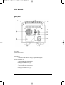
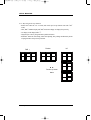
4.2. Name of Each part
■Front panel
Function
(1) Front cover
(2) Operating panel
(3) Open knob
(4) Power switch
(5) Logo label
(6) Door panel
Product Description 13
IFM500(영문) 1904.2.3 9:48 PM 페이지14
001 pdf-in
FETAL MONITOR
■Rear panel
Mark
RS-232C
DCP
UC
(7) Rear cover
(8) Lift handle
(9) Event marker socket
: Connect Event Marker to this connector.
(10) Serial port
: Connect PC to this connector using by supplied cable. (option)
(11) DOP I transducer port
: Connect DOP probe to this connector.
It is displayed to FHR I overlay part.
(12) DOP Ⅱ transducer port
: Connect DOP probe to this connector.
It is displayed to FHR I overlay part.
14 Product Description
IFM500(영문) 1904.2.3 9:48 PM 페이지15
001 pdf-in
IFM-500
(13) Power inlet
(14) Protect ground
(15) Tocotransducer port
: Connect UC probe to this connector.
(16) Main label
(17) Speaker
Auxiliary equipment connected to the system interface must be certified according to the
respective IEC standard (e.q. IEC 950 for data processing equipment configurations shall comply
with the system standard IEC 60601-1.) Everybody who connects additional equipment to the
signal input part or signal output part configures a medical system, and therefore responsible that
the system complies with the require-ments of the system standard IEC 60601- 1. If in doubt,
consult the technical service department of your local representative.
To avoid electrical shock, do not open the cabinet. Refer servicing to qualified personnel only.
Da Gefahr eines elektrischen Schlags besteht, darf das Gehause nicht geoffnet werden.
Uberlassen Sie Wartungsabeiten stets einem Fachmann.
Pour eviter tout risque d’ electroncution, ne pas ouvrir le coffret. Confier l’ entretien uniquement
a un personnel qualifie.
Product Description 15
IFM500(영문) 1904.2.3 9:48 PM 페이지16
001 pdf-in
FETAL MONITOR
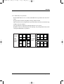
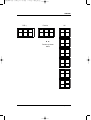
■Control panel
Function
(18) DOP I Select lamp
(19) DOP I rhythm lamp
(20) FHR I display
(21) DOP I volume up button
(22) DOP I volume down button
(23) DOP Ⅱ Select lamp
(24) DOP Ⅱ rhythm lamp
(25) FHRⅡ display
(26) DOPⅡ volume up button
(27) DOPⅡ volume down button
(28) UC display
(29) Reference button
(30) UC bar display
(31) Calibration button
(32) Record ON lamp
(33) Record button
(34) Alarm on lamp
(35) Alarm button
16 Product Description
IFM500(영문) 1904.2.3 9:48 PM 페이지17
001 pdf-in
IFM-500
CHAPTER 5
INSTALLATION
■Precaution
Please be sure following precautions for installing and use.
- Use and keep IFM-500 at temperature and humidity 10 ~ 40。
C and 30 ~ 85 % respectively.
- Check the connecting status of power cord and transducer cable for smooth using.
- Don’
t plug several cord in one electric outlet.
- Place main body at plain spot.
- Connect ground wire, or noise can be caused.
- Don’
t use outlet to which electric appliances causing noise are connected.
- Protect enough space for proper use.
- All memories of set-up mode are remaining by internal batteries even when turn the unit off.
Memories can be changed by electric and other shocks so please memorize.
- Protect transducers from concussion because they are breakable easily.
- Use only ultrasound gel for transducer and clean it after use for keeping. Water and oil are
prohibited from using.
- Consider temperature and humidity for installing and keeping away from dust and explosive
material.
5.1. Transducer and Event marker Connection
- Connect Ultrasound transducer I to Doppler I connectors at rear side of main body.
- Connect tocotransducer to UC(15) connector at rear side of main body.
- Connect Event marker to MARK(9) connector at rear side of main body.
Installation 17
IFM500(영문) 1904.2.3 9:48 PM 페이지18
001 pdf-in
FETAL MONITOR
5.2. Recording paper Installation
- Open printer door by pushing open knob(3) stationed at door cover.
- Insert recording paper into its compartment and make recording side face upward.
- Put the end of paper on driving black roller and close the door cover.
- Make the end of paper and end of door parallel.
- Thermal printer head can be damaged if door cover are closed without paper.
5.3. Power Connection
- Connect IFM-500 to AC power inlet(13) by using power cable.
18 Installation
IFM500(영문) 1904.2.3 9:48 PM 페이지19
001 pdf-in
IFM-500
CHAPTER 6
SET-UP MODE
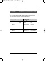
6.1. Initial Set-Up
Time, date, Printer record speed, Record contrast, Auto-record period, FHR alarm limits,etc. are
pre-setted as belows. And you can change the value as you like.
Subject
Time and Date
Record Speed
Record Contrast
Auto-record Period
FHR Alarm
Parameter
Offset Mode
Alarm Mode
Item
Year
Month
Date
Hour
Minute
Second
cm/min
minute
Upper Limit
Lower Limit
Pre-setting Value
Current Time
3
1
0
190
110
OFF
ON
Set-up Mode 19
IFM500(영문) 1904.2.3 9:48 PM 페이지20
001 pdf-in
FETAL MONITOR
6.2. Set-Up Function
6.2.1. Time & Date set-up function
- Push “CAL” button for over 2 seconds, then you can hear “Beep” sound saying ready for
setting-up.
- Adjust year, month, date, hour, minute and seconds with FHR I volume buttons
- Adjust numeric values with Function button.
- Auto repeat function is supplied by pushing the button for over 2 seconds.
- Push “REC” button for memorizing values after adjusting. This pushing simultaneously
means escaping from time & date set-up function.
▲ ▼
▲ ▼
FHR Ⅰ
Volume
button
Function
button
20 Set-up Mode
IFM500(영문) 1904.2.3 9:48 PM 페이지21
001 pdf-in
IFM-500
6.2.2. FHR Alarm set-up function
- Push“ALARM”
button for over 2 seconds, and FHR alarm set-up function starts with“Bee”
sound.
- Set upper and lower limit by using FHR I volume up and down button.
- Adjust numerical value by using Function up and down button. The total measurement range
of FHR is from 50 to 240 bpm.
- Auto repeat function is supplied by pushing the button for over 2 seconds.
- Push“REC”
button for memorizing values after adjusting. This pushing simultaneously means
escaping from FHR alarm set-up function.
▲ ▼
▲ ▼
FHR Ⅰ
Volume
button
Function
button
Set-up Mode 21
IFM500(영문) 1904.2.3 9:48 PM 페이지22
001 pdf-in
FETAL MONITOR
6.2.3. Record speed set-up function
- Push“R E F”
button for over 2 seconds, and record speed set-up function starts with“Bee”
sound.
- Then,“REC”
on FHR I display and“SPd”
on Function display are displayed respectively.
- UC display can be displayed like“3”
.
- Adjust numeric value by using Function up and down button.
- Push“REC”
button for memorizing values after adjusting. This pushing simultaneously means
escaping from Record speed set-up function.
FHR Ⅰ
Function
▲ ▼
Function up / down
button
22 Set-up Mode
UC
IFM500(영문) 1904.2.3 9:48 PM 페이지23
001 pdf-in
IFM-500
6.2.4. Record contrast set-up function
- Push“R E F”
button for over 2 seconds, and record period set-up function starts with“Bee”
sound.
- Then,“R E C”
on FHR I display and“C o n”
on Function display are displayed respectively.
- UC display can be displayed like“1”
.
- Adjust numeric value by using Function button.
- Push“REC”
button for memorizing values after adjusting. This pushing simultaneously means
escaping from record contrast set-up function.
- Each set-up value is the list below.
1 : normal
2 : normal X 2
3 : normal X 3
4 : normal X 4
FHR Ⅰ
Function
UC
▲ ▼
Function up / down
button
Set-up Mode 23
IFM500(영문) 1904.2.3 9:48 PM 페이지24
001 pdf-in
FETAL MONITOR
6.2.5. Auto-record period set-up function
- Push“REF”button for over 2 seconds, and auto-record period set-up function starts with
“Bee”
sound.
- Then,“REC”
on Function display and“Prd”
on Function display are displayed respectively.
- UC display can be displayed like“0”
.
- Adjust numeric value by using Function button.
- Push“REC”button for memorizing values after adjusting. This pushing simultaneously
means escaping from record period set-up function.
- Each set-up value is the list below.
0 : continuous
1 : 10 minutes
2 : 20 minutes
3 : 30 minutes
4 : 40 minutes
5 : 50 minutes
6 : 60 minutes
24 Set-up Mode
IFM500(영문) 1904.2.3 9:48 PM 페이지25
001 pdf-in
IFM-500
FHR Ⅰ
Function
UC
▲ ▼
Function up / down
button
Set-up Mode 25
IFM500(영문) 1904.2.3 9:48 PM 페이지26
001 pdf-in
FETAL MONITOR
CHAPTER 7
OPERATION
■ Initial status (Power on)
When you turn on the unit, it will be seen like belows on displays which are blinking for 3 times
while hearing“Beep”
sound. After this, unit are going into stand-by status for operation.
FHR Ⅰ
Function
UC
7.1. Control panel
The color of each lamps stationed on control panel are indicating specific status. Also, each
function and operation are fulfiled by button and LED display are displaying current status and
output value.
■Lamp
DOP I seletion lamp
FHR I rhythm lamp
Record on lamp
Alarm on lamp
26 Operation
: It will light when DOP I transducer is used.
: As signal quality indicator, green light is blinking when
good signal are captured and red light is blinking when
noise present.
: It will light when record operation is on status.
: It will light when alarm is on status.
IFM500(영문) 1904.2.3 9:48 PM 페이지27
001 pdf-in
IFM-500
■Buttons
DOP I volume up / down
Function up / down
Alarm
Cal
Rec
Ref
: Fetal heart beat sound of DOP I is going up/down. In
set-up mode, values are going up/down.
: In set-up mode, values are going up/down.
: Alarm on and off status are inter-changeable by one
pushing and can be entered into set-up mode by
pushing the button for over 2 seconds.
: Fulfil self-test operation by one-pushing of this button
and enter into time & date set-up status by pushing for
over 2 seconds.
: Record on and off status are inter-changeable by one
pushing. Recording paper can be coming out at high
speed by pushing this button for over 2 seconds. One
pushing in set-up mode means of escaping from set-up
mode after memorizing all parameters.
: One pushing make current UC value“10”
and pushing
over 2 seconds make unit into record speed set-up
mode.
■ Signal display LED
FHR I LED
UC LED
UC bar
: Display value of fetal heart rate of DOP I.
: Display current UC value and tocotransducer connection status.
: Display UC value as a form of LED bar.
■ Others
Open knob(3)
Power switch(4)
: Push this knob to open door cover.
: Push to turn it on and see if the color of front is green or black. Green
is indicating turn on status and black means turn off status.
Operation 27
IFM500(영문) 1904.2.3 9:48 PM 페이지28
001 pdf-in
FETAL MONITOR
7.2. FHR (Fetal Heart Rate)
■In case of transducer disconnection
FHR I display LED is in off status.
■In case of DOP transducer connection
1) Selection indicator lamp turned on is indicating related Dop transducer is connected.
2) If there is no signal inputed to the transducer connected,“0”
will be on FHR I display.
3) Heart rhythm lamp is blinking concurrently with fetal heart beating. Also it turn into green
to indicate correct FHR and red to indicate incorrect FHR.
■Adjusting volume
1) To increase or decrease the size of volume, push volume up and down button of FHR I.
2) Volumes are consisted of 16 steps and if surpass the biggest one, it turns back to the smallest
one again and vice versa.
3) Push volume up and down button simultanously to stop volume tentatively. And push any
button, up or down, to restart sound.
28 Operation
IFM500(영문) 1904.2.3 9:48 PM 페이지29
001 pdf-in
IFM-500
7.3. UC (Uterine Contraction)
■In case of transducer disconnection
UC value display and LED bar are turn off.
■In case of tocotrnasducer connection
1) UC display and LED bar is displaying current value respectively.
2) Value“10”setting of UC value can be made by one touching of“REF”button. So, Push
“REF”
button before starting UC operation.
3) UC LED bar is indicating the UC value in a form of bar.
7.4. Alarming
1) Basically, alarm function is set as‘on’
status when the unit is turned on.
2) If value of FHR I or II is deviating from the range of value set by alarm set-up function,
alarming sound“Beep”
will be heard.
3) If you push alarm button one time when you hear alarming, alarming sound, alarm lamp and
alarm function will be turned off. If you push alarm button again, alarm function and lamp
will be back to‘on’
status.
7.5. Recording
1) All value of FHR FM and UC are recorded on recording paper if you push“R E C”button
one time and simultaneously record lamp is on.
2) You can stop record operation by pushing“REC”
button one time during recording.
3) If you push“REC”button for over 2 seconds during non-recording status, line-feed
function(recording paper are coming out at fast speed without recording) will be started.
Line feed function will last if you keep pushing“REC”
button.
Operation 29
IFM500(영문) 1904.2.3 9:48 PM 페이지30
001 pdf-in
FETAL MONITOR
7.6. Event Marking
- If you push marker switch during operation, arrow mark will be recorded on the paper.
Detailed explanation of recording shape will be handled in chapter 10.
7.7. Self-test (Calibration) operation
- Check the connection of transducers, power and paper loading.
- Push power switch(14) so that you will see green light on front face of power switch.
- After turned on IFM-500, it will start operation with the“Beep”
sound.
- Self-test operation will be started if calibration button on front panel are pushed.
- 120, 160, and 50 are displayed on FHR I and UC value LED respectively and printed out as
it is. After then, it turn back to normal operation status immediately.
(Note : If no transducers are connected, no recording paper are inserted and cover are open error
message will be displayed on display LED. In this case, self-test and normal operation will be
stopped.)
30 Operation
IFM500(영문) 1904.2.3 9:48 PM 페이지31
001 pdf-in
IFM-500
CHAPTER 8
HOW TO USE TRANSDUCERS
8.1. Doppler measurement method
IFM-500 is designed to measure FHR by using ultrasound which is high frequency waves above
the range of audible to the human ears. Ultrasound is transmitted to fetal heart wall through
abdominal of pregnant woman and ultrasound frequancy reflected by moving heart wall is
changed by movement of fetal heart wall. We call above situation as doppler effect which is
usually used in measuring fetal heart rate. Ultrasound is harmless to human body so that it is
applicable to so variety of medical fields.
One important factor to consider in measuring FHR by doppler principle is ultrasound attenuation.
If air bubble are existing between contacting surface of transducer and maternal abdominal wall,
ultrasonic attenuation will occur.
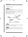
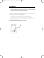
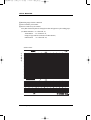
Please follow following order in using transducer
① Please search the patients’ abdomen for fetus back-side, on which you put DOP transducer.
In case fetus is laying as below drawing, please put the transducer as shown.
If you put the transducer on the front-side of fetus, focusing is often distracted and you can’t
get correct data.
How to use Transducers 31
IFM500(영문) 1904.2.3 9:48 PM 페이지32
001 pdf-in
FETAL MONITOR
When fetus is heading down-ward or up-ward, you have to pay attention on placing the
transducer. Please put the transducer around the navel of patient.
② Moving the transducer slowly, search for the position where you can hear heart-beating more
clearly. Then, fasten belt after positioning the transducer.
Do not push the volume button until you find a correct position with transducer.
When you position transducer on the correct position and hear relatively clear heart
- beating sound and FHR rhythm lamp blinking green light as per heart-beating you can adjust
volume button as you like.
③ Carefully fasten the belt so that the transducer don’t slip away.
As shown on the left drawing, you need to arrange the transducer up-ward of patient. Then,
you can minimize cable damage and use it more conveniently.
32 How to use Transducers
IFM500(영문) 1904.2.3 9:48 PM 페이지33
001 pdf-in
IFM-500
8.2. UC measurement method
Tocotransducer is used in measuring external uterine contraction with the help of belt.
Tocotransducer affixed on maternal abdominal wall is measuring UC by the pressure made by
uterine contraction.
Please follow following order in using tocotransducer.
① Place tocotransducer at 10 Cm upper of navel and fasten with belt. If tocotransducer are
placed at below of navel, measurement can be influenced by maternal respiration.
② Fasten transducer with belt. At this time, UC value must show about 20 ~ 90.
③ Push“REF”button to make UC value“10”
④ When uterine contraction are not occure, check the place of tocotransducer again.
After fastening transducer with belt, you need to push“REF” button one time before use.
Afterward, UC reference is automatically setted.
If you want to change transducer position, you need to try above four steps again.
You can print by pushing“REC”button after Dop transducer and tocotransducer are placed
at right position.
How to use Transducers 33
IFM500(영문) 1904.2.3 9:48 PM 페이지34
001 pdf-in
FETAL MONITOR
CHAPTER 9
ERROR MESSAGE AND COUNTERMEASURE
Error message will be displayed on FHR I, II display LED. When error messages are occurs,
please refer to following chart for error message signal and countmeasure.
FHR Ⅰ, Ⅱ LED
Alarming
ERR 001
Three “Beep”
Sound
ERR 002
Factors causing
error
Countermeasure
Door Panel is
open
Close the Door
Panel
“
No paper loaded
Load paper
ERR 003
“
ERR 001 and
002 are occurred
simultaneously
Load paper and
close Door Panel
ERR 004
“
Transducers are
disconnected
Connect transducer
34 Error Message and Countermeasure
IFM500(영문) 1904.2.3 9:48 PM 페이지35
001 pdf-in
IFM-500
CHAPTER 10
RECORDING PAPER
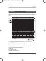
IFM-500 will start recording with one pushing of “REC” button and output from of recording is as
below.
①
③
④
⑥
⑦
① Use and non-use indication of DOP I transducer.(OFF→not using, ON→ using)
② Waveforms of FHR I.
③ Current time and minutes. Current year, month and date.
④ Use and non-use indication of tocotransducer. (OFF→ not using, ON→ using)
⑤ Current recording speed.
⑥ Upper and lower limit value set by alarm function.
⑦ Offset status.
⑧ Recording range of FHR I.
⑨ Recording range of fetal movement.
Recording Paper 35
IFM500(영문) 1904.2.3 9:48 PM 페이지36
001 pdf-in
FETAL MONITOR
⑩ Recording range of uterine contraction.
⑪ Arrow marked by event marker.
⑫ Time is recorded every five minutes.
If any data recorded on printer are changed, new data will appar on top of recording paper.
(Ex: DOP I transducer : on - off and off - on,
Tocotransducer : on - off and off - on,
Change of upper and lower limit value of alarm function,
Offset function : on - off and off - on)
<Self-test form>
①
③
④
⑥
⑦
36 Recording Paper
IFM500(영문) 1904.2.3 9:48 PM 페이지37
001 pdf-in
IFM-500
A. AFTERSERVICE
If there are any problems with the equipment, please follow the steps below :
Contact the BIONICS Oversea Service Department immediately. After gathering the model
name, Serial Number, date of purchase, and description of the problem contact BIONICS with
the information shown below.
Try to solve the problem over the phone with the service department personnel. If the problem
can not be solved over the phone, the service personnel can came and fix the problem directly.
BIONICS or local distributor will make available on request circuit diagrams, component part
lists, descriptions, calibration instructions or other information which will assist your
appropriately qualified technical personnel to repair those parts of equipment which are
designated by BIONICS as repairable.
A. Afterservice 37
IFM500(영문) 1904.2.3 9:48 PM 페이지38
001 pdf-in
FETAL MONITOR
B. WARRANTY
■ BIONICS Corp. guarantees all new equipment ainst faults in materials or workmanship for a
period of one year from date of shipment to purchaser. BIONICS Corp. will, as sole and
exclusive remedy, at no charge, replace any such defective unit returned to its service
department within the designated warranty period.
■ This warranty applies only to failures from operatingthe equipment under conditions for which
it was designed. Warranted equipment is to be used only for the intended and labeled
indications presented in the literature accompanying the equipment.
■ This warranty does not cover loss or dame resulting from external causes, such as, but not
limited to, fire, flood, windstorm, hail, lightning, earthquake, theft, misuse, or abuse. Dame
caused by equipment relocation is not coverd.
■ This warranty is void in cases where the product has been damed as a result of an accident,
misuse, abuse, dropping, abnormaloperating conditions, or attempts to modify or alter any part
or assembly.
■ Cosmetic defects or deterioration will not be refinished or replaced. The costs of training
materials, or supplies are not covered.
■ BIONICS Corp. will not be responsible for any loss, dame, or injury resulting from delay in
rendering service under this warranty.
■ BIONICS Corp. will not be responsible to you for incidental or consequential dames of any
kind arising from connected with the use of its equipment.
■ When you have a problem with warranted BIONICS Corp. equipment, please notify BIONICS
Corp. of the Model, Serial Number, Date of Purchase, and nature of the problem. BIONICS
Corp. will replace defective equipment at no cost to you. BIONICS Corp. will pay the shipping
and insurance costs of equipment sent to you.
■ Defective equipment shipped from you to BIONICS Corp. must be packed in the replacement
cartons. Shipping and insurance costs for the return of the defective equipment must be prepaid by you.
■ This limited warranty is in lieu of all other warranties expressed or implied, including
warranties of merchant ability or fitness for any particular use. No representative or other
person is authorized to represent or assume for BIONICS Corp. any warranty liability beyond
that set forth herein.
38 B. Warranty
IFM500(영문) 1904.2.3 9:48 PM 페이지39
001 pdf-in
IFM-500
EC Declaration of Conformity
0470
Manufacturers Name :
BIONICS Corp.
Manufacturers Address :
214-3, Sangoan-Ri, Hongchun-Eub,
Hongchun-Gun, Kangwon Do
Declares that the product :
Korea
Product Name :
Fetal Monitor
Model Number :
IFM-500
to which this declaration relates is in conformity with the European Directive :
93/42/EEC
“Council Directive of 14 June 1993 on the approximation of the laws of the Member States
concerning medical devices.”
The technical documetation and full compliance with the standard(s) or other normative
documents listed below proves the conformity with the essential requirements of the abovementioned EC Directive :
Safety Performance
EN 60601-1 : 1990+A1:1993+A2:1995
{IEC60601-1:1988+A1:1991+A2:1995}
EMC :
EN 60601-1-2 : 1993 {IEC 60601-1-2 : 1993}
Conducted Emission :
Radiated Emission :
ESD :
Radiated lummunity :
Fast Transients/Bursts :
Surges :
CISPR 11 : 1990 : Class A
EN 55011 : 1991 {CISPR 11 : 1990} : Class A
IEC 801-2 : 1991 [CD=3kV : AD = 8kV]
IEC 801-3 : d1992 [3Vm@80% sin. Mod.]
IEC 801-4 : 1998 [AC=1kV; DC=0.5kV:I/O=0.5kV]
IEC 801-5 : d1993 [DM=1kV: CM=2kV]
Supplementary Information
The devices are Class IIb.
The devices were tested in a typical configuration of a BIONICS IFM-500 Fetal monitor.
(Quality Control Team Manager - Kwak Dong Hun)
39