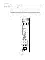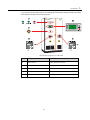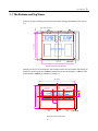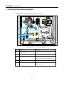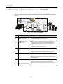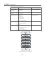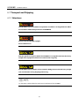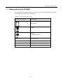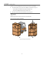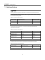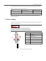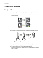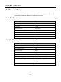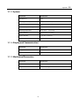
1
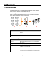
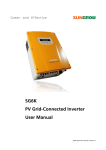
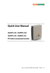
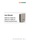
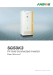
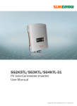
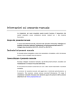
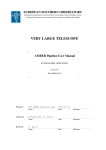
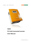
SG100KU
PV Grid-Connected Inverter
Installation Manual
SG100KU-IEN-Ver13-201202
Version: 1.3
About This Manual
Thank you for purchasing the SG100KU from Sungrow Power Supply Co., Ltd.. We hope you
will be satisfied with this device along with your entire PV plant system.
Aim
The aim of this manual is to give safety instructions, detailed setup information for the
installation of SG100KU PV grid-connected Inverter.
Target Readers
The manual is provided to people who need to set up a system that includes the SG100KU
grid connected inverter. Installers must be qualified electricians only.
How to Use This Manual
Read this manual and the other documents, before installation of the SG100KU.
The document must be stored near the installation and must be available at all times.
The contents of this manual will be periodically updated or revised if necessary. However
discrepancies cannot be excluded. Please make the object as the standard or download
the latest version of this manual via www.sungrowpower.com.
I
IMPORTANT SAFETY INSTRUCTIONS
SAVE THESE INSTRUCTIONS
Symbols Explanation
Important instructions contained in this manual should be followed during installation of
the inverter. And they will be indicated by these symbols.
DANGER indicates a hazard with a high level of risk which, if not avoided, will result
in death or serious injury.
WARNING indicates a hazard with a medium level of risk which, if not avoided, could
result in death or serious injury.
CAUTION indicates a hazard with a low level of risk which, if not avoided, could result
in minor or moderate injury.
NOTICE indicates a situation which, if not avoided, could result in equipment
malfunction or property damage.
NOTE indicates additional information, emphasized contents or tips to help you solve
problems or save time.
II
Contents
About This Manual .................................................................................................................................... I Aim ..................................................................................................................................................... I Target Readers..................................................................................................................................... I How to Use This Manual............................................................................................................................. I IMPORTANT SAFETY INSTRUCTIONS.............................................................................................................. II SAVE THESE INSTRUCTIONS ......................................................................................................................... II Symbols Explanation .......................................................................................................................... II 1 Safety Instructions ................................................................................................... 1 1.1 Appropriate Usage .............................................................................................................................. 2 1.2 Safety Instructions .............................................................................................................................. 3 1.3 Emergency Stop Button ...................................................................................................................... 5 1.4 Grid (AC) Main Switch.......................................................................................................................... 5 1.5 DC Main Switch................................................................................................................................... 6 1.6 Open the Door of SG100KU ................................................................................................................. 6 2 Delivery ..................................................................................................................... 7 2.1 Scope of Delivery ................................................................................................................................ 8 2.2 Identify SG100KU ................................................................................................................................ 9 2.3 Storage of SG100KU .......................................................................................................................... 10 3 Introduction ............................................................................................................ 11 3.1 Basic Structure and Appearance......................................................................................................... 12 3.2 Dimensions and Weight .................................................................................................................... 14 3.3 The Bottom and Top Views................................................................................................................. 15 3.4 Electrical Connections Interface ......................................................................................................... 16 3.5 Data Acquisition................................................................................................................................ 17 3.5.1 Data Display ............................................................................................................................. 17 3.5.2 Fault Indication ........................................................................................................................ 17 3.5.3 Serial Data Access ..................................................................................................................... 17 3.6 General Requirements ....................................................................................................................... 17 3.6.1 Grid Requirements.................................................................................................................... 17 III
3.6.2 Ventilation Requirements .......................................................................................................... 17 3.6.3 Installation Requirements ......................................................................................................... 17 3.6.4 Personnel Requirements ........................................................................................................... 18 3.6.5 Communication Requirements.................................................................................................. 18 4 Installation Design ................................................................................................. 19 4.1 The Solution with Optional Devices from SUNGROW .......................................................................... 20 4.2 Basic Requirements ........................................................................................................................... 21 4.3 Installation Environment Design ........................................................................................................ 21 4.3.1 Floor ........................................................................................................................................ 21 4.3.2 Clarence Space ......................................................................................................................... 22 4.3.3 Cable Trench ............................................................................................................................ 22 4.3.4 Ventilation................................................................................................................................ 23 4.3.5 Other Protections ..................................................................................................................... 23 4.4 Wiring Specification .......................................................................................................................... 24 4.5 Tightening Torques and Cable Protection ........................................................................................... 25 4.5.1 Tightening Torques for Power Cable Connections....................................................................... 25 4.5.2 Cable Protections ..................................................................................................................... 25 4.6 Installation Process ........................................................................................................................... 25 5 Preparations for Installation ................................................................................ 27 5.1 Checking the Unit ............................................................................................................................. 28 5.2 Required tools .................................................................................................................................. 28 6 Mechanical Installation ......................................................................................... 29 6.1 Transport and Shipping ..................................................................................................................... 30 6.1.1 Attentions ................................................................................................................................ 30 6.1.2 Moving the Packed SG100KU .................................................................................................... 31 6.2 Field Installation ............................................................................................................................... 35 6.2.1 Unpacking the Unit .................................................................................................................. 35 6.2.2 Place the SG100KU ................................................................................................................... 36 6.2.3 Fastening the SG100KU to Floor ................................................................................................ 36 7 Electrical Connection............................................................................................. 37 7.1 Cable Specifications .......................................................................................................................... 38 7.2 Parts for Cabling ............................................................................................................................... 39 7.3 Start Electrical Connections ............................................................................................................... 40 7.3.1 Open the Door ......................................................................................................................... 40 7.4 Open the Cable Holes........................................................................................................................ 41 7.5 DC Connections ................................................................................................................................ 42 7.6 AC Grid Connections ......................................................................................................................... 44 7.7 Ground Connections ......................................................................................................................... 45 IV
7.8 Communication Connection (Optional).............................................................................................. 47 7.9 Close the Cable Holes ........................................................................................................................ 48 8 Installation Checklist ............................................................................................. 49 9 Commissioning ....................................................................................................... 51 9.1 Requirements of Commissioning ....................................................................................................... 52 9.2 Inspection before Start-up................................................................................................................. 52 9.2.1 PV Array Check ......................................................................................................................... 52 9.2.2 SG100KU Check ........................................................................................................................ 52 9.2.3 Ground Connection Check ........................................................................................................ 52 9.2.4 Serial Communication Check (Optional) .................................................................................... 53 9.2.5 Voltages Check ......................................................................................................................... 53 9.3 Start the Inverter ............................................................................................................................... 53 9.4 Complete the Commissioning ........................................................................................................... 54 10 Appendix ............................................................................................................... 55 10.1 Technical Data ................................................................................................................................. 56 10.1.1 DC Parameters ........................................................................................................................ 56 10.1.2 AC Parameters ........................................................................................................................ 56 10.1.3 System ................................................................................................................................... 57 10.1.4 Display and Communication ................................................................................................... 57 10.1.5 Mechanical Parameters ........................................................................................................... 57 10.2 Exclusion of Liability ........................................................................................................................ 58 10.3 About Us ......................................................................................................................................... 59 V
Figures
Fig 1-1 PV Generation System with SG100KU .......................................................................................................................................... 2
Fig 2-1 Nameplate ............................................................................................................................................................................................. 9
Fig 3-1 Simple Circuit Diagram of SG100KU ........................................................................................................................................... 12
Fig 3-2 External Appearance of SG100KU ................................................................................................................................................ 13
Fig 3-3 Dimensions and Weight of SG100KU.......................................................................................................................................... 14
Fig 3-4 Bottom View of SG100KU ............................................................................................................................................................... 15
Fig 3-5 Top View of SG100KU ....................................................................................................................................................................... 15
Fig 3-6 Electrical Connections Interfaces of SG100KU ........................................................................................................................ 16
Fig 4-1 The Solution from SUNGROW ....................................................................................................................................................... 20
Fig 4-2 Clearance Space around the SG100KU ...................................................................................................................................... 22
Fig 4-3 Sectional Drawing of Cable Trench ............................................................................................................................................. 23
Fig 4-4 Installation Process of the SG100KU ........................................................................................................................................... 26
Fig 6-1 Moving the Packed SG100KU ........................................................................................................................................................ 32
Fig 6-2 Using a Forklift to Move the SG100KU with the Wooden Pallet ........................................................................................ 33
Fig 6-3 Using a Forklift to Move the SG100KU ....................................................................................................................................... 33
Fig 6-4 Using Rail Steels or Crane to Move the SG100KU ................................................................................................................... 34
Fig 6-5 Cross-section View of the SG100KU Fasten on the Wooden Pallet ................................................................................... 35
Fig 6-6 Fastening the SG100KU ................................................................................................................................................................... 36
Fig 7-1 Power Cable Connection Terminal .............................................................................................................................................. 39
Fig 7-2 Open the Main Switches ................................................................................................................................................................. 40
Fig 7-3 Open the Latch ................................................................................................................................................................................... 40
Fig 7-4 Remove the Protective Shield ....................................................................................................................................................... 41
Fig 7-5 DC Input Cable Routing .................................................................................................................................................................. 43
VI
Fig 7-6 AC Output Cable Routing ............................................................................................................................................................... 44
Fig 7-7 Ground Cable Routing ..................................................................................................................................................................... 46
Fig 7-8 Serial Communication Cable Routing ........................................................................................................................................ 47
Fig 7-9 Serial Communication Interface Connection........................................................................................................................... 47
VII
Tables
Table 1-1 System Devices Type...................................................................................................................................................................... 2
Table 2-1 Scope of Delivery ............................................................................................................................................................................ 8
Table 4-1 Min. Distances between Control Cable and Power Cable ............................................................................................... 24
Table 4-2 Tightening Torques for Power Cable Connections ............................................................................................................ 25
Table 4-3 Installation Process Descriptions ............................................................................................................................................. 26
Table 6-1 Symbol and Data Name on Crate ............................................................................................................................................ 31
Table 7-1 DC Cables Recommended Sizes .............................................................................................................................................. 38
Table 7-2 AC Cables Recommended Sizes ............................................................................................................................................... 38
Table 7-3 Ground Cables Recommended Sizes ..................................................................................................................................... 38
Table 7-4 Communication Cables Recommended Sizes .................................................................................................................... 39
VIII
1
Safety Instructions
About This Chapter
This chapter describes the appropriate usage and provides some important safety
instructions about SG100KU.
1
SG100KU
Installation Manual
1.1 Appropriate Usage
Grid-Connected PV system consists of PV modules, grid-connected inverters, metering
device and power distribution system (as shown in Fig 1-1).
The solar energy is converted into DC current by PV modules and is fed into the local
power grid network by the grid-connected inverter which synchronized the frequency,
phase and pure sine waveform with the power network.
Fig 1-1 PV Generation System with SG100KU
No.
Description
A
PV Arrays
B
SG100KU PV Grid-Connected Inverter
C
Utility Grid
Table 1-1 System Devices Type
Device
Type
PV Arrays
Monocrystalline Silicon, Polycrystalline Silicon, Amorphous Silicon,
Thin Film Cells
Utility Grid
TT, TN-C, TN-S, TN-C-S, IT
Optional Devices
Solar Info EM Environment Monitoring Device
SunBox PVS PV Array Combiner Box
SunBox PMD-D DC Power Distribution Cabinet
SunBox PMD-A AC Power Distribution Cabinet
Solar Info Logger Inverter Data Acquisition and Transmission Device
2
Safety Instructions
1
1.2 Safety Instructions
Pay attention to the following safety instructions:
Shock Hazard!
Death results from burning and electric shock upon touching the SG100KU live
components.
z
Do not touch the live components of the SG100KU.
z
Observe all safety regulations.
Shock Hazard!
The enclosure of SG100KU inverter may contain high voltage conductors. The
enclosure doors should be kept locked during operation, except for maintenance or
testing.
To avoid the risk of electric shock, do not perform any action or operation which is
not included in the operating instructions unless you are qualified to do so.
Shock Hazard!
The SG100KU inverter will immediately shutdown if users want to open the front
door during operation.
Please check the unit is thoroughly shut down and isolated from the public grid and
PV arrays before opening the front door.
To avoid the risk of electric shock, a minimum 5 minutes is needed for any stored
potentials that still left in the inverter after shut-down to be discharged before
opening the door.
3
SG100KU
Installation Manual
Lethal Voltage!
Damage to the SG100KU may result death by electric shock or fire!
z
Only operate SG100KU when it is safe to do so!
z
Only operate SG100KU when no damage is visibly apparent!
DC Voltage!
The PV array will provide DC voltage to the inverter when exposed to light, which
may cause an electrical shock during installation, wiring or maintenance if not
covered.
Limitation of Use!
The SG100KU Photovoltaic Grid-Connect Inverter is not intended for use in
connection with life support systems or other medical equipments or devices.
z
Do not install on or over combustible surfaces.
z
More than one live circuit, see diagram.
ESD Protection!
The SG100KU may be damaged irreversibly by electrostatic discharge (ESD) at its
components.
z
During the operation of SG100KU, please observe all the ESD related safety
regulations!
z
Discharge any ESD by touching the grounded SG100KU conductor before
contacting any electronic components!
4
Safety Instructions
1
For use in a controlled environment, refer to manual for environmental conditions.
Service Safety!
Thoroughly inspect the equipment prior to energizing. Verify that no tools or
equipment have inadvertently been left behind.
Never work alone when servicing this equipment. Two persons are required until the
equipment is properly de-energized, locked out and verified de-energized with a
meter.
Please keep this installation the manual and other related documents in the handy place of
the SG100KU.
These documents must be available to operators and maintenance personnel at all times.
1.3 Emergency Stop Button
The Emergency stop button will shutdown the inverter (disconnects the AC contactor and
stops the IGBT matrix) immediately when it is punched (pressed down).
The inverter must be started up manually through LCD control menu if users want to
recover the operation after the button is punched.
1.4 Grid (AC) Main Switch
The grid main switch is one of the primary disconnects for the inverter. The inverter's doors
cannot be opened until the switch of the grid main switch is in the OFF position. When the
AC main switch is in the OFF position, all AC power is disconnected (not live), except the
following areas:
z
The input side of the AC circuit breaker (the utility grid)
z
The DC input terminals (if the PV array is connected and energized)
5
SG100KU
Installation Manual
To operate the inverter the AC circuit breaker switch must be in the ON position.
1.5 DC Main Switch
The DC main switch is also the primary disconnect for the inverter. The inverter's doors
cannot be opened until the switch of the DC circuit is in the OFF position.
When the DC main switch is in the OFF position, all DC power is disconnected (not live),
except the following areas:
z
The input side of the AC main switch (the utility grid)
z
The DC input terminals (if the PV array is connected and energized)
To operate the inverter the DC circuit breaker switch must be in the ON position.
1.6 Open the Door of SG100KU
Use the following procedure to shut down the SG100KU inverter before servicing:
1.
Stop the inverter from the LCD control menu.
2.
Switch off the AC main switch (turn the switch to OFF position)
3.
Switch off the DC main switch (turn the switch to OFF position).
4.
Press in the handle to make it pop out from the lock hole, turn it right.
5.
Now you can open the front door.
6
2
Delivery
About This Chapter
This chapter provides the scope of delivery of SG100KU, nameplate and storage method.
7
SG100KU
Installation Manual
2.1 Scope of Delivery
The following materials in Table 2-1 should be included in the crate.
Table 2-1 Scope of Delivery
No.
Name
Note
1
SG100KU PV Grid-Connected Inverter
Including key and parts for cabling
2
SG100KU Installation Manual
-
3
SG100KU Operation Manual
-
4
Warranty Card
-
5
Certificate of Quality
-
6
Product Test Report
-
User can download the latest version of this manual and the monitoring software via
www.sungrowpower.com.
8
Delivery
2
2.2 Identify SG100KU
You can identify the SG100KU using the nameplate. There are two nameplates located on
the back panel and inside the door as shown in Fig 2-1.
Fig 2-1 Nameplate
*The picture is for reference only; the actual item is standard.
No.
Description
A
SUNGROW Logo and product type
B
Parameters
C
Marks of certification institutions of SG100KU
D
Company name, website and origin
9
SG100KU
Installation Manual
2.3 Storage of SG100KU
If there is a long time before installation or operation, SG100KU should be deposited
appropriately.
z
Pack SG100KU up in the crate.
z
Keep the desiccant bags in the crate.
z
SG100KU can only be stored when it is stopped and all the doors are closed in a dry
room to protect the internal circuits against dust and moisture.
z
Routine check at least once a week.
z
Unpacking check and change desiccant bags every 6 months.
Keep the crate upright.
No stacking on top of the crate.
After long term storage, a thorough test of SG100KU is necessary.
10
3
Introduction
About This Chapter
This chapter provides basic information about SG100KU.
11
SG100KU
Installation Manual
3.1 Basic Structure and Appearance
SG100KU is an advanced and reliable three-phase grid connected inverter for solar power
generation system with a rating of 100kW.
The SG100KU inverter utilizes the advanced power conversion technology with the latest
IGBT, to convert the DC power from the photovoltaic array to stable three-phase AC power
and then feed the power to the utility grid through filter and isolation transformer, see Fig
3-1.
Fig 3-1 Simple Circuit Diagram of SG100KU
12
Introduction
3
Fig 3-2 shows the locations of basic controlling and information display elements that help
users perform control and monitoring tasks.
Fig 3-2 External Appearance of SG100KU
No.
Component Name
Comments
A
LED Indicators
Power, Operation and Fault
B
LCD and Keys
Display data and perform control functions
C
Emergency Stop Button
Shut down the inverter when pressed down
D
DC Main Switch
DC side circuit breaker switch
E
GRID Main Switch
AC side circuit breaker switch
13
SG100KU
Installation Manual
3.2 Dimensions and Weight
The SG100KU inverter’s dimensions are 40inchx77inchx30inch(1020mmx1964mmx770mm,
W×H×D, including the devices on the front panel). The SG100KU inverter weighs
approximately 1984 Ibs (900 kg). Please take this large dimensions and heavy weight into
consideration during shipping, moving and installation.
Fig 3-3 Dimensions and Weight of SG100KU
14
Introduction
3
3.3 The Bottom and Top Views
Cables and a part of cooling air come into the cabinet through the bottom panel, see Fig
3-4.
1.2 in.
4x0.55in.x0.79in.
11.8 in.
11.8 in.
5.9 in.
5.9 in.
25.6 in.
31.5 in.
Unit:inch
Fig 3-4 Bottom View of SG100KU
Cooling air is fed in via the base inlet and shutters on front and rear panels. The cooling air
outlets are on the top of the SG100KU. Cooling fans’ power consumption is 240W and the
outlet air flow is 60000ft3/h (1620m3/h), see Fig 3-5.
36.8 in.
10.4 in.
60000ft3/h
7.1 in.
11.3 in.
10.8 in.
25.6 in.
10.4 in.
5.7 in.
Unit:inch
Fig 3-5 Top View of SG100KU
15
SG100KU
Installation Manual
3.4 Electrical Connections Interface
SG100KU provides multiple electrical terminals, see Fig 3-6.
A
B
C
D
E
Fig 3-6 Electrical Connections Interfaces of SG100KU
No.
Name
Comments
A
RS485 Terminals
-
B
DC- Input Terminals
-
C
AC Output Terminals
To 3-phase Grid through AC main breaker.
Leave N Vacant in 3-phase-3-wire grid system
D
DC+ Input Terminals
-
E
Ground Terminal
Must be connected to protect operators from
leakage current.
16
Introduction
3
3.5 Data Acquisition
3.5.1 Data Display
The inverter will display real-time and logged running data of the inverter to the equipped
LCD interface.
3.5.2 Fault Indication
The inverter can record the time and type of all faults in non-volatile memory and inform
the fault state to the customers through LCD and LED.
3.5.3 Serial Data Access
All the data and fault information can be accessed by a remote computer via serial port
communication when necessary.
The inverter has a basic RS485 communication method and can be extended to a variety of
communication approaches, which including Ethernet, Internet, and GPRS by utilization of
proper external adapters or modems.
3.6 General Requirements
3.6.1 Grid Requirements
The output of SG100KU is designed to fit the 480V 3-phase-4-wire grid system, which
includes L1, L2, L3, Neutral and power ground. 480V 3-phase-3-wire grid is acceptable. In
3-phase-3-wire grid, neutral terminal of SG100KU can be left vacant.
3.6.2 Ventilation Requirements
Maintain a minimum of 24inch (600mm) clearance in back, 48inch (1200mm) in front and
24inch (600mm) on top of the SG100KU for proper ventilation and installation operation.
3.6.3 Installation Requirements
All installation practices on the SG100KU may only be performed when the device is safely
de-energized with all the DC and AC power sources and all the power switches are secured
against being switched on.
SG100KU are designed with some fans for cooling and ventilation.
17
SG100KU
Installation Manual
Work on the fans may only be performed after all insulation measures have been taken.
3.6.4 Personnel Requirements
Only qualified technical personnel, who are familiar with the installation of the system,
may undertake any such work.
3.6.5 Communication Requirements
The basic communication interface of SG100KU is a RS485 serial communication, which
can be easily connected to a PC through a RS485/RS232 Converter.
An Ethernet method and GPRS method can be extended optionally with specific device,
which can also be ordered from Sungrow.
18
4
Installation Design
About This Chapter
This chapter provides the PV plant system solution with optional devices from SUNGROW,
information about how to design the installation environment, how to arrange installation
procedure. Read this chapter to get information for installing the SG100KU.
19
SG100KU
Installation Manual
4.1 The Solution with Optional Devices from SUNGROW
PV Grid-connected system configured with optional devices from SUNGROW is shown in
Fig 4-1.
Fig 4-1 The Solution from SUNGROW
No.
Name
Comments
A
Solar Info EM Environment
Monitoring Device
Applied to PV power generation system to measure the wind
speed, wind direction and solar radiation.
B
SunBox PVS PV Array
Combiner Box
By using PV array combiner box, different strings of PV array
can be converged into the PV array string box. After that,
together with lightning arresters and circuit breakers, it is
connected to the inverter to reduce the system installation
time and increase the system safety.
C
SunBox PMD-D DC Power
Distribution Cabinet
The DC distribution unit collects the DC current from PV arrays
and feeds into the inverter, which mainly contains DC input
circuit breakers, diodes and PV lightning protection device.
D
SunBox PMD-A AC Power
Distribution Cabinet
The AC distribution unit is a distribution and protection
interface between inverter and the utility network, which
contains grid-side circuit breaker, lightning protection devices
and power meters.
E
Solar Info Logger
Inverter Data Acquisition
and Transmission Device
Data acquisition device is used for processing the data from PV
power plants which can be communicated with the PV
grid-connected inverter for PV power plants. It is capable of
monitoring one singular inverter and even up to 100 inverters.
20
Installation Design
4
4.2 Basic Requirements
Following requirements listed below are met to ensure the normally operating of
SG100KU.
z
Avoid moisture and wet place.
z
Install indoor and avoid sunlight and rain.
z
Don’t install SG100KU in unstable place.
z
Install in the place where you can see the LED indicators or LCD display clearly.
z
Ambient temperature range: -13°F~131°F (-25°C~55°C).
z
Maintain spaces around the SG100KU for proper ventilation, installation operation or
passage (escape route).
z
Good ventilation and clean cooling air supply
4.3 Installation Environment Design
There are air outlets on the top of the SG100KC. Therefore, at on-site field, air ducts
must be installed to avoid foreign bodies’ entry.
The SG100KU should be installed in electrical service room. The floor, wall clearances,
ventilation equipments and precaution devices should be designed by professional
personnel and satisfy the following requirements.
4.3.1 Floor
The foundation must guarantee solid and safe positioning of the inverter. It must provide
the load-carrying capacity necessary to cope with the weight of the inverter.
SG100KU is designed for indoor use only and must be placed to a level concrete floor or
pad.
Any existing unevenness, depressions or slope must be corrected prior to installation.
Prior to placing the inverter, users should bear in mind that the cables should enter the
inverter from underneath and through the cable entry holes.
21
SG100KU
Installation Manual
4.3.2 Clarence Space
Maintain a minimum of 24inch (600 mm) clearance in back, 48inch (1200mm) in front and
24inch (600mm) on top of the SG100KU for proper ventilation and installation operation.
The space from the top of the enclosure to the installation site ceiling must be left enough
for ventilation and maintenance; otherwise maintenance personnel cannot open the top
panel.
Fig 4-2 Clearance Space around the SG100KU
4.3.3 Cable Trench
The external cables of the SG100KU route into or out of the cabinet via the base. Cable
trenches or steel supports above the floor are recommended (Refer to relevant design
guides or standards).
Well electrical connection is needed between different cable trenches and GND
terminals.
22
Installation Design
4
Cable support arms can be used to support cables. Signal cables should be separated from
power cables for a distance to avoid interference.
A
B
Fig 4-3 Sectional Drawing of Cable Trench
No.
Name
A
Cable Trench
B
Cable Support Arms
4.3.4 Ventilation
The heat generated (exhaust hot air) by the SG100KU must be dissipated out of the
electrical service room as soon and as much as possible, in order to guarantee safe
operation and high feed-in power.
z
High circulation of air is required.
z
Plenty of fresh air is available.
z
Air is pure and without dusts (classification 3S2).
z
Ventilation equipments are necessary, e.g. fans, blowers, ventilation grilles.
z
Exhaust fans are recommended to keep air pressure balance.
z
Directions of air inlet and outlet should be designed according to the local wind
direction.
z
Measures for dust and rain-proof of air inlet and outlet are necessary.
z
The sizes of air pipes should be designed according to the air quantity by professional
personnel.
4.3.5 Other Protections
The SG100KU has the Ingress Protection 20(TYPE 1), and should be installed in dry, clean
industrial environment in the term of EMC threshold and noise level.
23
SG100KU
Installation Manual
During operating the SG100KU will make some noise (≤80db), install the SG100KU in
industrial environment and avoid the vicinity to living area or office area.
After wiring, the cable entry and exit holes should be covered by the slid plates. And the
rest gaps should be filled by urethane foam in order to keep mouse or other creatures from
entering the cabinet.
Installation location must be dry, including no unexpected condensation.
4.4 Wiring Specification
Cables in SG100KU can be classified into power cable and control (data) cable.
It is recommended that the power cable and control cables be installed on separate cable
support arms. Avoid long parallel runs of the two kinds of cables in order to decrease
electromagnetic interference.
Where control cables must cross power cables make sure they are arranged at an angle as
near to 90° as possible. Do not run extra cables through the inverter.
The cable support arms must have good electrical bonding with each other and to the
grounding electrodes. Aluminum cable support arm systems can be used to improve local
equalizing of potential.
Table 4-1 shows the recommended minimum distances between different parallel lengths
shielded control cable and power cable.
Table 4-1 Min. Distance between Control Cable and Power Cable
Parallel length (inch,m)
Min. Distances (inch,m)
7874 inch (200m)
12 inch (0.3m)
11811 inch (300m)
20 inch (0.5m)
19685 inch (500m)
48 inch (1.2m)
24
Installation Design
4
4.5 Tightening Torques and Cable Protection
4.5.1 Tightening Torques for Power Cable Connections
Tighten the cable with the proper torque shown in Table 4-2; for fear of loosen of cable lugs
that may cause poor contact or high contact resistance, even fire.
Table 4-2 Tightening Torques for Power Cable Connections
Screw size
Torque(in-Ibs, N·m)
M4
18 in-Ibs (2 N·m)
M5
28 in-Ibs (3.2 N·m)
M6
62 in-Ibs (7 N·m)
M8
142 in-Ibs (16 N·m)
M10
301 in-Ibs (34 N·m)
4.5.2 Cable Protections
z
Protection of communication cable:
−
Communication cables are thin and easily to be broken. Lay power cables first then
communication cables.
−
Communication cables should be laid in cable trench or cable support arms or
tighten up by cable ties.
−
z
Avoid heat element and the strong electric filed.
Protection of power cables:
−
Strong electric current in power cables. Protect the insulating layer from sharp
edges.
−
Tighten power cables up with insulated cable ties if necessary.
4.6 Installation Process
Fig 4-4 shows the installation process of the SG100KU. And Table 4-3 gives a description
about it.
25
SG100KU
Installation Manual
Table 4-3 Installation Process Descriptions
Process
Specification
Reference
Preparations before
Installation
Checking the unit
5 Preparations for Installation
Mechanical
Installation
Transport and shipping
Electrical Connection
Open the door
Required tools
6 Mechanical Installation
Field installation
7 Electrical Connection
DC connections
AC grid connections
Ground connection
Communication connection
Installation Check
Check mechanical installation
8 Installation Checklist
Check electrical connection
Others
Commissioning
Check before commissioning
Preparations before start-up
Start-up procedure
Complete the commissioning
Fig 4-4 Installation Process of the SG100KU
26
9 Commissioning
5
Preparations for Installation
About This Chapter
This chapter illustrates preparations for installation of the SG100KU, including checking the
unit and required tools.
27
SG100KU
Installation Manual
5.1 Checking the Unit
The first thing users must do after receiving the unit is to check the packaging and the
device for any possible damage, verify the contents of the delivery with the delivery list.
Please contact Sungrow immediately in case you find any visual damage or lost of the
delivery components supposed to be included in the package.
Check that there are no signs of damages. Before installation and operation, check the
information on the crate to verify that the delivery is of the correct type.
Only intact unit may be installed!
5.2 Required tools
The tools required for moving the unit to its final position, fastening it to the floor,
tightening the connections are listed below:
z
Crane, fork-lift or pallet truck (check load capacity), rail steels, jack and rollers
z
Torque wrench
z
Screwdrivers for the tightening of the frame screws
z
Set of wrenches and sockets
z
Wire stripper
z
Pliers
z
Inner hexagon spanner
z
Alcohol blast burner or hot air blower
z
Meg-ohmmeter or multimeter
28
6
Mechanical Installation
About This Chapter
This chapter describes the mechanical installation procedure of the SG100KU.
29
SG100KU
Installation Manual
6.1 Transport and Shipping
6.1.1 Attentions
The SG100KU inverter should be transported or installed as an integrated unit. Never
disassemble it without the permission of SUNGROW.
Always keep the SG100KU upright!
Avoid sudden force!
Only the specific transport methods for SG100KU are acceptable. And note the heavy
weight of the equipment and the non-central center of gravity.
The SG100KU inverter weighs at least 1984 Ibs (900kg). Please take this heavy weight
into consideration during shipping and moving.
Lay the power cables before the mechanical installation of the SG100KU.
30
Mechanical Installation
6
6.1.2 Moving the Packed SG100KU
Pay attention to the symbols and data on the crate, to make an informed choice on modes
of transport and installation site, see Table 6-1.
Table 6-1 Symbol and Data Name on Crate
Symbol or Data Name
Specification
THIS END UP
KEEP UPRIGHT
FRAGILE
KEEP DRY
CAUTION AGAINST WET
MODEL NO.:
Type of the inverter
SIZE:
Package Dimensions
N. W.:
Net Weight
G. W.:
Gross Weight
31
SG100KU
Installation Manual
Forklift or crane can be employed to move the crate that contains the SG100KU.
z
z
The recommended way to transport the SG100KU is using forklift, see Fig 6-1 A:
−
Place the forks of the forklift to the bottom of wooden crate.
−
Elevate the SG100KU from beneath the wooden crate.
The crane can be used to move the wooden crate, see Fig 6-1 B:
Flexible slings with lock catches on both ends are recommended.
You can order the slings from SUNGROW.
Fig 6-1 Moving the Packed SG100KU
32
Mechanical Installation
Move the SG100KU after Unpacking
Forklift, rail steels or crane can be employed to move the SG100KU after unpacking.
z
If the unpacked SG100KU is far from the final position, the wooden pallet could be
moved with the SG100KU, see Fig 6-2.
Fig 6-2 Using a Forklift to Move the SG100KU with the Wooden Pallet
z
Using a forklift to move the SG100KU as following procedures, see Fig 6-3:
1.
Remove the front and rear base covers.
2.
Place the forks of the forklift below the SG100KU at the points specified.
3.
Lift the SG100KU from beneath the enclosure.
Be sure to use a forklift with a sufficiently spaced fork span.
Fig 6-3 Using a Forklift to Move the SG100KU
33
6
SG100KU
Installation Manual
z
Using rail steels to move the SG100KU to the final position, see Fig 6-4 A.
Lubricant can be sprayed on the surface of the rail steels to make the movement easier.
z
If the only available way to move the SG100KU is by crane, you can order the angle
irons and relevant parts for lifting from SUNGROW for free; see Fig 6-4 B.
Fig 6-4 Using Rail Steels or Crane to Move the SG100KU
34
Mechanical Installation
6.2 Field Installation
6.2.1 Unpacking the Unit
To unpack the SG100KU from the shipping crate:
1.
Remove the crate’s wood side and top panels.
2.
Remove the barrier bag material from the inverter.
3.
Remove the inverter’s anchor hardware that bolts the inverter to the pallet.
−
Remove the front and rear base covers.
−
Unscrew the nuts under the wooden pallet.
−
Pull up the bolts.
Fig 6-5 Cross-section View of the SG100KU Fasten on the Wooden Pallet
35
6
SG100KU
Installation Manual
6.2.2 Place the SG100KU
To place the enclosure on the mounting surface:
1.
Make sure the mounting surface is level.
2.
Move the SG100KU into position.
6.2.3 Fastening the SG100KU to Floor
SG100KU must be fastened to the floor as follows:
1.
Remove the front and rear base covers.
2.
Fasten the cabinet to the channel steels or floor using M12 bolts and nuts, see Fig 6-6.
Fig 6-6 Fastening the SG100KU
36
7
Electrical Connection
About This Chapter
This chapter describes the step-by-step electrical connection process needed to complete
the installation the SG100KU.
37
SG100KU
Installation Manual
7.1 Cable Specifications
All wiring methods and processes should be in accordance with Local Electrical Code.
The DC input cables (including DC positive and DC negative) must be chosen according to
the recommended rating below.
Table 7-1 DC Cables Recommended Sizes
Cables and Bolt
Requirements (mm2)
Requirements (AWG)
DC + cable
At least 2 input cables with each 70 mm2
1/0
DC- cable
At least 2 input cables with each 70 mm2
1/0
M8 Bolt (DC + and DC-) Torque: 16N.m
The AC output cables (including L1, L2, and L3) must be chosen according to the
recommended sizes below.
Table 7-2 AC Cables Recommended Sizes
Cables and Bolt
Requirements (mm2)
Requirements (AWG)
Grid phase L1 cable
70 to 85
2/0 to 3/0
Grid phase L2 cable
70 to 85
2/0 to 3/0
Grid phase L3 cable
70 to 85
2/0 to 3/0
Grid phase N cable
70 to 85
2/0 to 3/0
M8 Bolt (L1, L2, L3) Torque: AWG 5 (16N.m)
The ground cables must be chosen according to the recommended sizes below.
Table 7-3 Ground Cables Recommended Sizes
Cables and Bolt
Requirements (mm2)
Requirements (AWG)
Ground cable
16
5
Earthing resistance should be less than 10W.
38
Electrical Connection
7
The communication cables must be chosen according to the recommended sizes below.
Table 7-4 Communication Cables Recommended Sizes
Cable
Requirements (mm2)
Requirements (AWG)
Communication cable
0.75
18
Shield cables are recommended.
Based on the above tables, users should use proper cables for different terminals with
different specifications.
7.2 Parts for Cabling
The parts for connecting power cables are provided on the copper bases. The sequence of
the parts is shown in Fig 7-1.
Incorrect connection of power cables will cause fires.
Follow the sequence when connecting the power cables.
No.
Name
A
Copper Bus
B
Power Cable Lug
C
Bolt
D
Locking Washer
E
Washer
F
Nut
Fig 7-1 Power Cable Connection Terminal
39
SG100KU
Installation Manual
7.3 Start Electrical Connections
7.3.1 Open the Door
The SG100KU is stopped and latched during shipping; users must open the front door of
SG100KU for wiring.
1.
Switch off both the AC and DC main switches (turn both the switches
counter-clockwise).
Fig 7-2 Open the Main Switches
2.
Press down the doorlock to release the latch handle and turn the handle clockwise.
Fig 7-3 Open the Latch
3.
First open the left half door and then the right half door, identify the 2 transparent
plastic shields (one in the upper position and one in the lower position).
4.
It is necessary to take down the lower protective shield for wiring.
Note that there are 4 screws (in the blue circle) to fix the shield, loose and take down
them all. See Fig 7-4.
40
Electrical Connection
7
Fig 7-4 Remove the Protective Shield
7.4 Open the Cable Holes
The external cables are routed into or out of the cabinet via the cable entry/exit holes at
the bottom the SG100KU. The corresponding sliding plates should be removed for wiring.
1.
Turn the screws in the back of the sliding plate counter-clockwise
2.
Slide the plates backwards, to open the holes.
The protective sponge tapes on the sliding plats protect the cables from scratch. Do
not take them down!
41
SG100KU
Installation Manual
7.5 DC Connections
The DC input copper bus is located in the lower left corner of the inverter; there are 6 DC
inputs in the DC copper bus with DT70 lugs.
Cables rated for a minimum of 600V are required for connecting the inputs of the inverter.
Because the maximum DC current may reach 340A and the connection terminals are
M8 lugs, at least two AWG 1/0 (70mm2) DC input cables for each DC polarity are
required.
The DC cables to be connected must be rated for a minimum of 600V.
Be careful not to connect the wrong DC input polarity.
The voltage of the PV array must never exceed the maximum permissible inverter
input voltage of 600V.
1.
Ensure that the DC cables with no electricity.
2.
Route the DC cables through the cable entry holes to the DC terminals, see Fig 7-5.
3.
Connect the cables to DC (+) and DC (-) terminal on the DC circuit breaker respectively,
refer to Fig 7-1.
4.
Attach the DC cables to the terminals using appropriate screws.
42
Electrical Connection
Fig 7-5 DC Input Cable Routing
DC- grounding is required in contract. It connect DC- terminal to ground copper bus by
leakage current sensor before leave factory. Therefore it is needed to firmly attach PE
copper bar to grounding electrode.
43
7
SG100KU
Installation Manual
7.6 AC Grid Connections
To reduce the risk of fire, connect only to a circuit provided with 340A maximum
branch circuits over current protection.
When connect external AC cables to the SG100KU, positive phasing sequence must be
maintained throughout the installation process.
The connection terminals are located in the lower right corner of cabinet. Connection
process as follows:
1.
Ensure that the AC grid cables with no electricity.
2.
Route the Line Grid L1, L2, L3 and Neutral cables through the cable entry holes to the
AC terminals, see Fig 7-6.
3.
Connect the cables to terminals marked L1, L2, L3 and N respectively, refer to Fig 7-1.
4.
Secure the AC Line cables to the terminal with screws.
Fig 7-6 AC Output Cable Routing
44
Electrical Connection
7
Note that the AC grid connection is designed to fit the 3–phase grid, which must be
provided by the end-user, using a 3-phase system equipped for 480 V.
In 3-phase-3-wire system, the “N” terminal could be vacant.
7.7 Ground Connections
It is crucial for safety to connect all inverters to ground via appropriately sized conductor.
PE copper bar has been firmly connected to enclosure of inverter inside the SG100KU
before delivery. Therefore it is needed to firmly attach PE copper bar to grounding
electrode.
The cross area of grounding cable is AWG 5 (16mm2). The grid impedance must not exceed
10Ω.
If there are one more inverters in parallel connection, a single-core yellow-green
cable at least AWG 5 (16mm2) is needed to connect enclosure of all inverter to make
equipotential for them.
This will prevent current occurring in the shielding layer of communication cable
because of different potential.
Connect the factory ground to the ground terminal with leaking current detector, to realize
the leaking current detect function. See Fig 7-7 .
45
SG100KU
Installation Manual
Fig 7-7 Ground Cable Routing
This product can cause a DC current in the external protective earthing conductor.
Where a residual current-operated protective (RCD) or monitoring (RCM) device is
used for protection in case of direct or indirect contact,
46
Electrical Connection
7
7.8 Communication Connection (Optional)
SG100KU supplies RS485 interface to install communication between inverter and a PC or a
data logger. And there is also a RS485/RS232 converter needed to connect SG100KU to PC
1.
Route the communication cables through the cable entry holes to the RS485 A/B
terminals, see Fig 7-8.
2.
Route the RS485A cable to the RS485/232 converter TX+ or RX+.
3.
Route the RS485B cable to the RS485/232 converter TX- or RX-.
4.
Secure the cables are tightened.
5.
Connect the RS485/232 converter DB9 to the PC DB9 serial port, see Fig 7-9.
Fig 7-8 Serial Communication Cable Routing
Fig 7-9 Serial Communication Interface Connection
47
SG100KU
Installation Manual
If there are two or more inverters to be monitored, install communication system in series.
z
RS485 cable should be shielded twisted-pair for good communication(RVVP-2*1.0
shielded twisted-pair cable is recommended).
z
Shielding layer of RS485 cable should be single-point grounded in the site of monitor
terminal.
7.9 Close the Cable Holes
After all the electrical connections, cable holes must be closed to protect interior against
dirt, soiling and creatures (mouse or pest).
1.
Slide the plates forward until the flexible sponges’ seals are pressed the cables.
2.
Turn the screws in the back of the sliding plate clockwise to fix the sliding plates.
3.
Seal the rest gaps with urethane foam.
48
8
Installation Checklist
About This Chapter
This chapter describes the items needed to verify whether your installation of the SG100KU
is correct.
49
SG100KU
Installation Manual
Check the mechanical and electrical installation of the inverter before commissioning. Go
through the checklist below with another person together.
Mechanical Installation
□
Check all the mechanical connections and make sure there is no damage, scratch or abnormal
parts
□
The inverter has been fixed properly to floor.
□
The clearance spaces around the inverter are proper.
□
The ambient operating conditions are within the allowed range.
□
Cooling air circulates smoothly.
□
Protective enclosure seal is of integrity and reliability
Electrical Installation
□
The inverter is grounded properly.
□
The polarity of PV input connections are correct.
□
The grid voltage matches the nominal output voltage of the inverter.
□
The grid connection to the output terminals is OK.
□
The communication cable connections are correct.
□
The communication cables are routed away from power cables.
□
Marks on the cables are correct, clear and distinguishable
□
Insulation shields are integrated and firm.
□
Warning labels are clear and distinguishable.
□
Make sure all the bolts that fix the cables are tightened and secured.
Other
□
There are no tools, foreign objects or dust from drilling inside the inverter.
□
No condensing or icing in the cabinet.
50
9
Commissioning
About This Chapter
This chapter describes how to start the SG100KU for the first time, including requirements
of commissioning, Inspection before start-up, start-up procedures and completing the
commissioning.
51
SG100KU
Installation Manual
9.1 Requirements of Commissioning
Before starting the device for the first time, all work performed on the device should
be checked thoroughly.
Check the voltages of AC and DC sides meet the requirements of SG100KU.
9.2 Inspection before Start-up
9.2.1 PV Array Check
Before start-up, check the PV array:
1.
Check open-circuit voltage of each PV string matches the nominal input voltage.
2.
Record the U-I curve if possible.
3.
Record the environmental parameters(temperature, radiation intensity)
4.
Measure and record the resistance of cables if possible.
9.2.2 SG100KU Check
Before start-up check the SG100KU:
1.
Ensure that the mechanical and electrical installation of the inverter has been checked
according to 8 Installation Checklist.
2.
Ensure that the DC and AC (GRID) Main switches are in OFF position.
3.
Ensure that the Emergency Stop Button is released and functional.
9.2.3 Ground Connection Check
Make sure the ground cable goes through the hole of the ground fault detection device
and is connected to factory ground securely.
52
Commissioning
9
9.2.4 Serial Communication Check (Optional)
For external communication monitoring, the data cables must be connected. Make sure
that the RS485 A and B cables are connected correctly and tightened to the RS485/232
converter.
Make sure the RS485/232 converter DB9 terminal is correctly connected to the PC DB9
serial port.
9.2.5 Voltages Check
AC Grid Voltage Check
It must be verified that the inverter is connected to the correct grid type and that a
right-hand rotary field exists on L1, L2, L3 and Neutral. The value of the AC line to line
voltage should be about 480 V.
DC Voltage Check
The DC connections are from the DC combiner boxes to the inverter.
The voltage on the individual DC cables should be almost the same value and must never
exceed the allowable maximum DC voltage.
Besides the voltage values, the polarity of the DC inputs must also be verified. All DC
connections should be checked to ensure that they are mechanically tight.
The DC cables to be connected must be rates for minimum of 600V.
9.3 Start the Inverter
If all tests and measurements have been performed, and all measured values lie within the
acceptable range, then the device can be switched on for the first time.
Before start up the SG100KU, ensure that:
z
Nobody is working on the inverter.
z
Cabinet doors are closed.
To start the SG100KU:
53
SG100KU
Installation Manual
1.
Verify 480 VAC voltage of the grid line to line voltage.
2.
Close the door of the enclosure.
3.
Turn the AC (GRID) main switch to the ON position.
4.
Turn the DC main switch to the ON position.
5.
It will take about 1 minute for the auto-initialization of the power conversion circuit
and the LCD panel. The “POWER” LED indicators both in the enclosure and in the LCD
panel will burn; the “com” LED indicator will flash every 2 or 3 seconds.
6.
If the DC voltage is below the DC voltage start point (Vpv<320V), then the “state” of
the LCD interface will always show “Start-up”;
7.
If the DC voltage exceeds the DC voltage start point (Vpv >320V) for 5 minutes, the
SG100KU will automatically change to “Run” state, the “OPERATION” LED on the front
door and the “RUN” LCD will both light, with the state of the LCD menu be changing
to “Run”.
8.
After the SG100KU entering normal operation, set the time to local time via LCD
control panel, refer to the User Manual.
Desynchronized time between the inverter and upper PC in the communication system
may result in communication failure.
9.4 Complete the Commissioning
If all the start procedures have been performed, check the operating condition of the
SG100KU.
1.
Check whether the following items are normal: noise, heat generation, no smoke or
unusual odor.
2.
Measure the grid-connected voltage, current and THD.
3.
Check the ground of cabinet.
4.
Check the LCD display and external communication.
So far, the commissioning of the SG100KU is completed.
SG100KU don’t need manual control in daily operation.
z
Keep the door closed and locked.
z
Key to the door must be stored by appointed personnel.
54
10
Appendix
About This Chapter
This chapter gives technical data of the SG100KU, exclusion of liability and the way to
contact us.
55
SG100KU
Installation Manual
10.1 Technical Data
The following tables list the technical data of the SG100KU. Basic production information
and performance of the SG100KU are available from these tables.
10.1.1 DC Parameters
Parameter
Specification
Max. DC Voltage
600Vdc
Start Voltage
320Vdc
MPP Voltage Range
300~600Vdc
Min. DC Voltage
300Vdc
Max. DC Power
105kWp
Max. Input Current
340A
Recommend PV Array Open Circuit Voltage
450V
10.1.2 AC Parameters
Parameter
Specification
Rated Output Power
100kW
Max. AC Output Current
140A
Rated Grid Voltage
480Vac
Grid Voltage Range
422V~528Vac
Rated Grid Frequency
60Hz
Grid Frequency Range
59.3Hz~60.5Hz
Output Current THD
<3% at nominal power
Power Injection
<0.5% of rated inverter output current
Power Factor (cosφ)
1
56
Appendix
10.1.3 System
Parameter
Specification
Max. Efficiency
97.2%
CEC Weight Efficiency
96.5%(with transformer)
Protection Degree
IP20 (Indoor)
Power Consumption at Night
<30W
Operating Temperature
-25°C ~ 55°C
Cooling Method
Controlled force-air cooling
Relative Humidity
0~95% Non-condensing
Max. Working Altitude
6667 ft
(TYPE1)
(-13~+13°F)
(2000m)
10.1.4 Display and Communication
Parameter
Specification
Display
LCD
Communication
RS485, Ethernet(Optional)
10.1.5 Mechanical Parameters
Parameter
Specification
Dimensions(W×H×D)
40inchx77inchx30inch
Weight
1984Ibs
57
(900kg)
(1020mmx1964mmx770mm)
10
SG100KU
Installation Manual
10.2 Exclusion of Liability
The content of these documents is periodically checked and revised, when necessary,
please call us or check our website www.sungrowpower.com for the latest information.
However discrepancies cannot be excluded. No guarantee is made for the completeness of
these documents. Please contact our company or distributors to get the latest version.
Guarantee or liability claims for damages of any kind are excluded if they are caused by
one or more of the following:
z
Improper or inappropriate use or install of the product
z
Installing or operating the product in an unintended environment
z
Installing or operating the product when ignoring relevant safety regulations in the
deployment location
z
Ignoring safety warnings and instructions contained in all documents relevant to the
product
z
Installing or operating the product under incorrect safety or protection conditions
z
Altering the product or supplied software without authority
z
The product malfunctions due to operating attached or neighboring devices beyond
allowed limit values.
z
In case of unforeseen calamity or force majeure.
The use of supplied software produced by Sungrow Power Supply Co., Ltd.. is subject to
the following conditions:
z
Sungrow Power Supply Co., Ltd. rejects any liability for direct or indirect damages
arising from the use of the Solar Info software. This also applies to the provision or
non-provision of support activities.
z
Using the Solar Info software for commercial purposes is prohibited.
z
Decompiling, decoding or destroying the original program, including Solar Info
software and the embedded software, is prohibited.
58
Appendix
10
10.3 About Us
Sungrow power supply is a China-leading manufacturer of various power electronics
products for renewable energy generation systems. Our products include converters,
inverters, battery chargers, and other power supplies for distributable generation system in
both grid-connected and stand-alone applications. The power rating of Sungrow products
covers from several hundred watt to large mega-watt systems.
The pursuit of Sungrow is to help our customers acquire stable and clean power with
minimum cost, maximum reliability and enhanced safety.
Contact Information
If you have any questions about this product, our hotline will be happy to assist you. Please
keep the following data when contacting Sungrow.
Company:
Sungrow Power Supply Co., Ltd.
Website:
www.sungrowpower.com
Contact:
Mr. Henry (Director of International Trade)
Email:
[email protected], [email protected]
Address:
No.2 Tianhu Rd., New & High Technology Industrial Development Zone, Hefei,
P.R.China.
Zip:
230088
Telephone:
+86 551 532 7834, +86 551 532 7845
Fax:
+86 551 532 7856
59
Sungrow Power Supply Co., Ltd.
Add: No.2 Tianhu Rd., New & High Technology Industrial
Development Zone, Hefei, P.R.China.
Contact: Mr. Henry (Director of International Trade)
Zip: 230088
Specifications subject to change without notice.
Web: www.sungrowpower.com
E-mail: [email protected]
Tel: +86 551 532 7834/532 7845
Fax: +86 551 532 7856