1
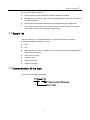
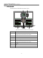
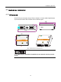
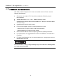
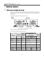
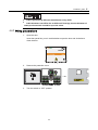
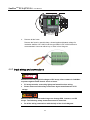
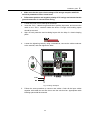
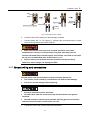
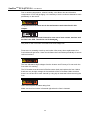
Contents
1 About this manual.................................................................................................. 1
1.1 Foreword........................................................................................................................................... 2
1.2 Contents............................................................................................................................................ 2
1.3 Target group...................................................................................................................................... 2
1.4 How to use this manual .................................................................................................................... 2
1.5 Symbols ............................................................................................................................................ 3
2 Safety instructions.................................................................................................. 5
3 Product description ................................................................................................ 9
3.1 System introduction ........................................................................................................................ 10
3.2 Supply list.........................................................................................................................................11
3.3 Demonstration of the type................................................................................................................11
3.4 Nameplate ...................................................................................................................................... 12
3.5 System composition........................................................................................................................ 13
3.5.1 Identifying the PVS................................................................................................................. 13
3.5.2 Inner structure ........................................................................................................................ 14
3.6 Fuse rating ...................................................................................................................................... 15
3.7 DC switch rating.............................................................................................................................. 15
3.8 Optional attachment........................................................................................................................ 15
4 Installation guide ................................................................................................. 17
4.1 Checking before installation............................................................................................................ 18
4.2 Tools preparation ............................................................................................................................ 18
4.3 Mechanical installation.................................................................................................................... 19
4.3.1 Dimensions............................................................................................................................. 19
4.3.2 Installation site requirements.................................................................................................. 20
4.3.3 Installation procedures ........................................................................................................... 21
4.4 Mechanical installation.................................................................................................................... 22
4.4.1 Water-proof terminals and wirings.......................................................................................... 22
4.4.2 Wiring preparations ................................................................................................................ 23
4.4.3 Input wiring and connections.................................................................................................. 24
I
4.4.4 Output wiring and connections............................................................................................... 26
4.4.5 Ground wiring and connections.............................................................................................. 27
4.4.6 Bottom wirings........................................................................................................................ 28
4.5 Start/stop of operation..................................................................................................................... 28
5 Routine maintenance ........................................................................................... 29
6 Appendix................................................................................................................ 31
6.1 Technical data ................................................................................................................................. 32
6.1.1 Technical data......................................................................................................................... 32
6.1.2 Cable requirements ................................................................................................................ 32
6.2 Quality Assurance........................................................................................................................... 33
6.3 About us .......................................................................................................................................... 34
II
1
About this manual
About this chapter
This chapter describes the main contents, target group, how to use this manual, and
symbols used in this manual.
1
SunBoxTM PVS-8/PVS-16
User Manual
1.1 Foreword
Thank you for purchasing the SunBoxTM PVS-8/PVS-16 from Sungrow Power Supply
Co., Ltd.. We hope that the device will meet your satisfaction when you use it with
your PV system.
1.2 Contents
Main contents of this manual are listed below:
z
Safety instructions
Safety instructions when you do the operation and maintenance work on
SunBoxTM PVS-8/PVS-16 (PVS).
z
Product description
Location of PVS in the generating system, and its structure, function and
classification.
z
Installation guide
The installation methods and communication connections will be described in this
part.
z
Routine maintenance
How to replace the fuses of PVS.
z
Others
Technical data of PVS, quality assurance and contact information of Sungrow will
be given in this part.
1.3 Target group
This manual is for users who operate the PVS or conduct the maintenance work. The
operators must be trained or qualified personnel.
1.4 How to use this manual
Read this manual and other documents before installation of the PVS.
The document must be stored near the installation and must be available at all times.
2
About this manual
1
The contents of this manual will be periodically updated or revised if necessary.
However discrepancies cannot be excluded. Please make the object as the standard
or download the latest version of this manual via www.sungrowpower.com.
1.5 Symbols
Important instructions contained in this manual should be followed during operation of
the PVS. And they will be indicated by these symbols.
DANGER indicates a hazard with a high level of risk which, if not avoided, will
result in death or serious injury.
WARNING indicates a hazard with a medium level of risk which, if not avoided,
will result in death or serious injury.
CAUTION indicates a hazard with a low level of risk which, if not avoided, will
result in minor or moderate injury.
NOTICE indicates a situation which, if not avoided, will result in equipment
malfunction or property damage.
NOTE indicates additional information, emphasized contents or tips to help you solve
problems or save time.
3
SunBoxTM PVS-8/PVS-16
User Manual
The following symbols on the device enclosure must be paid attention to.
Risk of electric shock! If not avoided, lethal hazard can be caused.
Hot surface! Do not touch!
The symbol represents protective conductor terminal. The terminal should be
connected firmly to avoid potential injury or property damage.
4
2
Safety instructions
About this chapter
This chapter describes some important safety instructions about SunBoxTM
PVS-8/PVS-16.
5
SunBoxTM PVS-8/PVS-16
User Manual
Please read the manual carefully before installation. If any device damage occurs
when ignoring the safety instructions, our company has the right to exclude all
warranty claims.
Shock Hazard!
Death results from burning and electric shock upon touching the PVS live
components.
z
Do not touch the live components of the PVS.
z
Observe all safety regulations.
Shock Hazard!
z
The enclosure of PVS may contain high voltages. Observe all the warning
markings on the device.
z
Observe all safety regulations in this manual.
Shock hazard!
Death results from burning and electric shock upon damaged device or system
malfunction.
z
Do the visual inspection before any operation.
z
Check the safety of all the device and circuits.
z
Ensure the safety before any operation.
z
Only qualified electricians can do the operation and wiring work.
z
The warning markings shall be clearly legible.
In each case, observe all the local regulations.
6
Safety instructions
2
PV arrays should be covered by the light-proof materials while they are
installed in the daytime, especially in high-radiation days. Otherwise PV
modules exposed to light may produce dangerous high voltages, which might
cause electrical shock.
Do not open the door of PVS too often. Frequent openings may weaken its
water-proof function.
Please make sure that all the connections are tightened correctly and firmly.
Our company has the right to exclude liability claims if the loss caused by the
improper use of the wires or the looseness of the wiring.
All the pictures in this manual are for orientative information only, and some
details may not exactly correspond to the product you received. Please prevail
in kind.
7
SunBoxTM PVS-8/PVS-16
User Manual
8
3
Product description
About this chapter
Product solutions, equipped features and hardware structures of PVS are described in
this chapter.
9
SunBoxTM PVS-8/PVS-16
User Manual
3.1 System introduction
For a large-scale grid-connected PV system, it is widespread to install a DC
combining device between PV modules and inverters to minimize cable connections,
facilitate maintenance and enhance reliability.
Our SunBox PVS combiner box series (PVS) are designed for meeting these
requirements, which can provide a turnkey solution for PV power plant systems.
Considering different types of PVS, a certain number of PV strings can be connected
to the input side of PVS. After combining work done, at the output side, there will be
one DC+ and one DC- main line. By using of surge protection device (SPD) and circuit
breakers, the output can be connected to inverters directly.
The PV generation system including a PVS is shown in Fig 3-1。
Fig 3-1 Composition of PV generation system
Table 3-1 Device in Fig 3-1
No.
Device
A
PV arrays
B
SunBoxTM PVS-8/PVS-16 combiner box
C
Sun Access Inverter
D
SolarInfoTM Logger Data acquisition device
E
SolarInfoTM EM Environment monitoring device
F
Utility Grid
For PVS-8, up to 8 PV strings can be connected to the input side. And for PVS-16, up
to 16 PV strings can be connected to the input side.
10
Product description
3
PVS has the following features:
z
IP65 protection degree makes the outdoor installation available.
z
Multiplex input PV strings, each channel is equipped with a fuse (can be replaced
by other rating fuse).
z
Both positive and negative electrodes are equipped with high voltage SPD.
z
A four-pole circuit breaker is connected in series on both positive and negative
electrodes, to improve DC withstand voltage value.
3.2 Supply list
Check the delivery for completeness after you receive the product. Following
materials should be included in the crate:
z
PVS
z
Key
z
Mounting ears: For easy installation, four mounting ears have been equipped on
the PVS before delivery.
z
User manual of PVS
z
Warranty card
z
Quality certificate
z
Product test report
3.3 Demonstration of the type
Type of the PVS is illustrated below:
11
SunBoxTM PVS-8/PVS-16
User Manual
3.4 Nameplate
Open the door of PVS by using the special key. The nameplate is situated on the
inside of the door.
Fig 3-2 Nameplate of PVS
Table 3-2 Nameplate Description
Parameters
Description
TYPE
Type of PVS
Serio No
Serial number, unique for the PVS
Date of manufacture
Date: month/day/year
Max. system voltage
Maximum voltage of the system
Max. No. of DC input circuits
Maximum number of the input PV arrays
Max. input fuse rating
Maximum fuse rating (choose the fuse according to the parameter)
Max. output current
Maximum output current
Max. continuous output
current
Maximum continuous output current
Protection degree
IP65 (outdoor)
Environment temperature
℃
The nameplate contains very important information of the product. Each
product has its own serial number and the number has also been archived by
Sungrow, including following maintenance information as well. Users should
protect the nameplate carefully.
12
Product description
3
3.5 System composition
3.5.1 Identifying the PVS
PVS-16 is shown in Fig 3-3, while PVS-8 has 8 water-proof terminals on both positive
and negative polarity respectively on the input side.
Fig 3-3 Identifying the PVS (take PVS-16 as an example)
No.
Name
Description
A
Lockhole
-
B
Mounting ear
Points mounting the PVS onto wall
C
INPUT DC+
Positive pole of DC input
(unused terminals must be sealed)
D
INPUT DC-
Negative pole of DC input
(unused terminals must be sealed)
E
Ground terminal
Equivalent potential connection terminal
F
MONITOR
Monitoring input and output
G
OUTPUT DC+
Positive pole of DC output
H
OUTPUT DC-
Negative pole of DC output
I
Wireless terminal
The terminal is unused, has been sealed
J
Valves for air
Air valve
13
SunBoxTM PVS-8/PVS-16
User Manual
3.5.2 Inner structure
The Inner structure of PVS-8/PVS-16 is shown in Fig 3-4.
Fig 3-4 Inner structure of PVS (take PVS-16 as the example)
No.
A
Description
Input of DC positive pole
(Equipped with fuse and fuse holder for each channel)
B
Output of DC positive pole
C
Ground terminal
D
Output of DC negative pole
E
Input of DC negative pole
(Equipped with fuse and fuse holder for each channel)
F
DC switch
G
SPD
H
Wire bus bar
14
Product description
3
Pictures above are for orientative information, and some details may not exactly
correspond to the product you received. Please prevail in kind.
3.6 Fuse rating
In power system, fuses are used for over-current protection. Choosing right-raring
fuses is very important to ensure safety operation.
The minimum current rating of a fuse can be calculated with short circuit current (Isc)
of PV arrays. Where there are no special needs, the recommended rating would be
1.56×Isc.
Users can calculate fuse rating easily. If maximum current of PV arrays=7A, and DC
voltage range of PV arrays=200~1000V, then the fuse rating will be 1000V/(1.56×7A).
3.7 DC switch rating
DC switch rating can be got from nameplate. The DC switch can endure at most
1000V. A four-pole circuit breaker is connected in series on both positive and negative
electrodes, to improve DC withstand voltage.
3.8 Optional attachment
z
Fuse puller
z
30V DC power supply (Just for external-supply type)
z
PV diode box
15
SunBoxTM PVS-8/PVS-16
User Manual
16
4
Installation guide
About this chapter
This chapter describes the environmental requirements for installation and the
installation methods for PVS.
17
SunBoxTM PVS-8/PVS-16
User Manual
4.1 Checking before installation
Check the delivery completeness after you receive the product. Following materials
should be included in the crate:
z
PVS
z
key
z
quality certificate
z
Warranty card
z
User manual of PVS
z
Product test report
PVS has been thoroughly checked and tested before delivery. However, damages
can be caused during shipping process. Users should check the device before
installation.
If any damage you’ve found, contact either transport company or Sungrow
immediately. A photo of damaged part will be helpful.
4.2 Tools preparation
Electric drill
Wrench
Screwdriver
Inner hexagon spanner
Expansion bolts (type: M8, number: 4)
Rolled angle
18
Installation guide
4
4.3 Mechanical installation
4.3.1 Dimensions
All the PVS have the same volume: 670mm×600mm×210mm (width×height×depth).
Input terminal numbers will be different due to different types.
210
600
560
A
670
460
640
B
Fig 4-1 Dimensions of PVS (PVS-16)
In the above Fig 4-1, functions of terminal A, B are reserved, and they must be
sealed.
19
SunBoxTM PVS-8/PVS-16
User Manual
4.3.2 Installation site requirements
With IP65 protection degree, the PVS can be installed outdoors. Please meet the
following requirements:
z
Dimensions and weight of PVS should be considered sufficiently. (as per
technical data).
z
Ambient temperature -25℃~+60℃; Relative humidity 0~99%.
z
Installation site should be as close as possible to PV arrays for minimum cables
and wires usage.
z
Installation site should be safe venting.
z
PVS must be installed vertically, including following two types:
- Wall-hung type: Fix the PVS onto a wall (recommended).
- Pillar-mounted type: Fix the PVS onto a pillar.
z
Never install the device in direct sunlight to guarantee optimal performance.
z
For big PV plants, it is suggested that the device is installed on the back side of
PV arrays.
z
For better heat dissipation and convenient maintenance, enough space must be
maintained for the PVS.
Avoid installation in rainy or high humidity days. The PVS can be damaged due
to a high relative humidity.
20
Installation guide
4
4.3.3 Installation procedures
If PVS is installed on the brackets of PV arrays, hexagon bolts (M8*25), washers (Φ8)
and spring washers (Φ8) will be needed. Users can also choose appropriate types
with specific installation conditions.
1.
The Installation holes should meet following requirements. (unit: mm)
Fig 4-2 Installation holes
2.
Install PVS by using hexagon bolts and hexagon nuts as described in Fig 4-3.
From left to right, they are: bolts, mounting ears, brackets, washers, spring
washers, nuts. Tighten nuts to install the PVS onto brackets firmly (Tightening
torque: 18Nm).
Fig 4-3 Installation guide
3.
Make sure that the PVS has been installed correctly and firmly.
z
PVS can also be installed for roof application.
z
Observe all the instructions in this manual and relevant documents.
21
SunBoxTM PVS-8/PVS-16
User Manual
4.4 Mechanical installation
4.4.1 Water-proof terminals and wirings
Ports for both internal and external connections are all in the bottom of PVS, and are
all water-proof. Provisions for connected cables shall be rated for and suitable for the
size and type.
Water-proof terminals of PVS are shown in Fig 4-4.
Fig 4-4 Size and type of water-proof terminals
Users can choose suitable cables as per Table 4-1.
Table 4-1 Suitable cables for water-proof terminals
Terminals
Size of
terminal
Cable
external
diameter
Size of cable
(recommended)
(mm)
PVS-8M
Spanner
diameter
PVS-16M
Input DC+
PGB9-09G
4.5~8
4 mm2~6 mm2
22/19
Input DC-
PGB9-09G
4.5~8
4 mm2~6 mm2
22/19
Monitor
Input/Output
PGB16-14G
8.5~14
ANT
PGB11-07G
4~7
-
24/22
GND
PGB11-10G
6~10
16 mm2
24/22
Output DC+
PGB21-18G
10~18
35mm2
70 mm2
46/42
Output DC-
PGB21-18G
10~18
35mm2
70 mm2
46/42
22
1.5 mm2 Four-core STP
with low resistance
24/22
Installation guide
z
4
Cables produced by different manufacturers may differ.
z
Cable diameters can differ due to different PV strings, but the diameter of
water-proof terminals should be up to the value.
4.4.2 Wiring preparations
1.
Open the door
Insert the special key, turn it anticlockwise to open the door and clockwise to
close the door.
2.
Remove the protection cover.
3.
Turn the switch to “OFF” position.
23
SunBoxTM PVS-8/PVS-16
4.
User Manual
Remove all the fuses.
Remove the fuses by special clamp, whose impulse withstand voltage for
insulation shall be over 1000V. And the type PM912 VDE 1000V/160mm is
recommended. Users can either buy or order it from Sungrow.
4.4.3 Input wiring and connections
Because of the very high DC voltages of PV arrays, direct contact is forbidden
to protect against lethal electric shock or burns.
z
PV arrays must be covered by light-proof materials when wiring.
z
Please observe all the safety instructions by the manufacturers of PV
strings.
Misconnections of cables and wirings can damage PVS, inverters, and PV
arrays. The following safety instructions must be observed:
z
Do all the wiring connections with the help of the circuit diagram.
24
Installation guide
4
z
Make sure that the open-circuit voltage of PV strings complies with PVS
technical parameters before insert fuses.
z
Differentiate positive and negative polarity of PV strings and ensure that the
ground connection is correct before wiring.
1.
Loosen the union nut of water-proof terminals.
2.
Insert the “PV1+” cable through terminals of positive input area, and connect the
cable to the “PV1+” terminal inside the device. Enough wire bending space
should be ensured.
3.
Strip off both protective and insulating layers with the help of a hand crimping
pliers.
4.
Loosen the tightening bolts by using a screwdriver, connect the cable conductor
to the terminal, and then tighten the bolts.
Fig 4-5 Wiring description
5.
Follow the same procedure to connect rest cables. Comb all the input cables
together with cable ties and firm them onto the wire bus bar. Appropriate cable
bending space shall be ensured.
25
SunBoxTM PVS-8/PVS-16
User Manual
Fig 4-6 Diagram of cabling route
4.4.4 Output wiring and connections
1.
Lift the protective cover upwards. Then loosen the nut from water-proof terminals.
2.
Insert the “DC+” cable through “DC Output (+)” terminal. Enough cable bending
space should be ensured.
3.
Strip off both protective and insulating layers with the help of a hand crimping
pliers. The length of cable conductor shall be approx. 25mm.
4.
Connect cable conductor to certain DT terminal. For PVS-8, 35mm2 terminal.
While for PVS-16, 70mm2 terminal.
5.
Insert the DT terminal, and tighten the nut by using an inner hexagon spanner.
Firm cable onto the wire bus bar. Appropriate cable bending space shall be
ensured.
26
Installation guide
4
Fig 4-7 Connection of DC cables
6.
Screw the bolt of the water-proof terminal tight clockwise.
7.
Connect cable “DC-” to “DC Output (-)” following the procedures above. Output
wiring and connections have been finished.
z
Make sure that the nuts have been screwed into place. If the cable
conductor has not been connected firmly, long-time work may burn the
terminal. Stranded flame-retarded copper wire shall be used, and its size shall
be over the recommended value as described in 7.1.2.
z
Nuts of water-proof terminals must be screwed correctly and firmly.
Otherwise, water leakage can damage the PVS.
4.4.5 Ground wiring and connections
Ground cables shall be connected correctly and firmly. Otherwise:
z
The electric shock caused by a malfunction can lead to lethal damage.
z
The device can be damaged when lightning.
z
Relevant standards must be observed.
z
Ground cables must be connected firmly with both device and ground
terminals.
z
Ground resistance shall be measured after finishing ground connections,
and the measured values should not be over 10Ω.
1.
Loosen the union nuts of GND water-proof terminals.
27
SunBoxTM PVS-8/PVS-16
User Manual
2.
Insert the green-yellow wire from the device outside into the “GND” water-proof
terminal, then pull the wire and connect it to the inner terminal. Enough wire
bending space should be ensured.
3.
Strip off both protection and insulation layers, with approx. 12mm conductor
length.
4.
Loosen the tightening bolt of “GND” terminal with the help of a screwdriver.
5.
Insert ground cable through the opening and screw the tightening bolts tightly.
Firm the cable onto the wire bus bar and enough cable bending space shall be
ensured.
6.
Tighten the nuts of water-proof terminal clockwise. Ground wirings have been
finished.
4.4.6 Bottom wirings
The bottom wirings are described in the following Fig 4-8.
Fig 4-8 Wiring connection illustration
Enough wire bending space is recommended to avoid stress on wires.
4.5 Start/stop of operation
PVS will start or stop working automatically when the power supply is on or off. The
DC output will be cut off by turning off the DC switch inside the device.
28
5
Routine maintenance
About this chapter
This chapter describes the routine maintenance work on PVS.
29
SunBoxTM PVS-8/PVS-16
User Manual
Due to ambient temperature, relative humidity, wind blown dust and vibrations,
components of PVS will get aging. It is necessary to do the routine maintenance work
periodically on the device.
Only qualified electricians can do the maintenance work described in this
chapter.
After the maintenance work finished, be sure not to leave screws, washers and
the like in the PVS. The device can be damaged!
Only work on the PVS when it is switched off and voltage free.
Fuses are non-resetting once they are broken. After many times replacement, the
fuse holders will get loose. Users should fasten the fuse holders periodically to ensure
valid connections.
The fuse withstands high voltages from the inverter and PV arrays. Do not touch the
fuse when it is working.
The DC breaker must be turned off before users check and replace the fuse. Notice
that there may be high voltages in the terminals of the DC breaker. Make sure that
there is no current left in each channel by using clip-on ammeter before removing the
fuse.
Users must replace the same rating fuse!
Make sure that fuse holder is fastened tight when the fuse is inserted.
30
6
Appendix
About this chapter
This chapter provides technical data of PVS, quality assurance, and the way to
contact us.
31
SunBoxTM PVS-8/PVS-16
User Manual
6.1 Technical data
6.1.1 Technical data
Types
PVS-8
PVS-16
Max. string number
8
16
Input current range
Refer to nameplate (the value can be changed by replacing
fuses)
Max DC voltage
0Vdc~1000Vdc
Degree of protection
IP65
Ambient temperature range
-25~+60
Relative humidity
99%
Weight approx.
28kg
Dimension(W×H×D)
670mm×600mm×210mm
31kg
6.1.2 Cable requirements
Types
PVS-8
PVS-16
Input cable
Type: 4 mm2~6mm2 Stranded flame-retarded copper wire
Stripped length: 10mm
Bolt: M4
Tightening torque: 1.2Nm
Output cable
2
Type: 35mm Stranded
flame-retarded copper wire
Output cable
Stripped length: 25mm
Bolt: M6
Tightening torque: 3.0Nm~
6.0Nm
Ground cable
Type: 15mm2 Four core STP with low resistance
Stripped length: 7mm
Bolt: M3
Tightening torque: 0.5Nm~0.6Nm
32
Appendix
6
6.2 Quality Assurance
Where any fault occurs during the warranty period, Sungrow will maintain or replace
the product for free.
Evidence
Sungrow Power Supply Co., Ltd. needs the users to provide the receipt invoice and
the date you purchase. Meanwhile the trademark should be clearly legible. Otherwise
Sungrow Power Supply Co., Ltd. has the right to exclude liability claims.
Conditions
z
The original unqualified product should return to Sungrow.
z
Users should permit appropriate time to maintenance the device with fault for
Sungrow.
Exclusion of liability
Guarantee or liability claims for damages of any kind are excluded if they are caused
by one or more of the following:
z
Improper, inappropriate use or installation of the product
z
Installing or operating the product in an inappropriate environment
z
Installing or operating the product when ignoring relevant safety regulations in
the deployment location
z
Ignoring safety warnings and instructions in all documents relevant to the product
z
Installing or operating the product under incorrect safety or protection conditions
z
Altering the product or supplied software without authorization
z
The product malfunctions due to operating attached or neighboring devices
beyond permissible limit values.
z
In case of unforeseen calamity or accidents
Where fault is caused by any of the above and users have the relevant demand,
Sungrow will do the paid maintenance work to the device after judgment.
Specifications subject to change without notice.
33
SunBoxTM PVS-8/PVS-16
User Manual
6.3 About us
Sungrow power supply is a china-leading manufacturer of various power electronics
products for renewable energy generation systems. Our products include converters,
inverters, battery chargers, and other power supplies for distributable generation
system in both grid-connected and stand-alone applications. The power rating of
Sungrow products covers from several hundred watt to large mega-watt systems.
The pursuit of Sungrow is to help our customers acquire stable and clean power with
minimum cost, maximum reliability and enhanced safety.
Trademarks
is a registered trademark of Sungrow Power Supply Co., Ltd.
Contact information
If you have any questions about this product, our hotline will be happy to assist you.
Please keep the following data when contacting Sungrow.
Company:
Sungrow Power Supply Co., Ltd.
Website:
www.sungrowpower.com
Contact:
Mr. Henry (Director of International Trade)
Email:
[email protected], [email protected]
Address:
No.2 Tianhu Rd. New & High Technology Industrial Development Zone,
Hefei, P.R.China.
Zip:
230088
Telephone:
+86 551 532 7834, +86 551 532 7845
Fax:
+86 551 532 7856
34
Sungrow Power Supply Co., Ltd.
Add: No.2 Tianhu Rd., New & High Technology Industrial
Development Zone, Hefei, P.R.China.
Contact: Mr. Henry (Director of International Trade)
Zip: 230088
Specifications subject to change without notice.
Web: www.sungrowpower.com
E-mail: [email protected]
Tel: +86 551 532 7834/532 7845
Fax: +86 551 532 7856