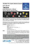
1
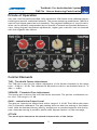
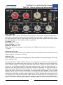
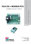
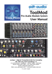
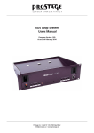
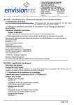
® ToolMod Pro-Audio Module System User Manual TM215b Stereo Mastering Peak-Limiter The TM215b is a very fast stereo peak limiter that can be used to limit the input level of a/d converters. Special additional features make the inaudible regulation of short signal peaks possible. Horizontal and vertical versions are available. Both versions are electrically identical. Only the orientation of the lettering and the knobs are different. The TM215b can be installed in any ToolMod frame. Content Principle of Operation....2 Control Elements....2 Basic Setup / Quick-Ref....3 Connectors....7 technical Specifications....8 Hint We assume that you are familiar with the basic principles of pro audio devices. Therefore, the explanations in this manual are limited to the special features and functions of the particular module. General information on many pro audio topics can be found on our web site http://www.adt-audio.com This manual is a supplement to the ToolMod User Manual that contains extensive information and safety instructions on the ToolMod® Pro-audio Module System by adt-audio®. If you don‘t have the ToolMod User Manual ask for a copy by email or fax, or download a PDF-version from one of our websites. It is imperative that you take account of the hints and safety instruction in the ToolMod User Manual that are not repeated in this supplement for a particular module. ® analoge + digitale Tonstudiotechnik Karl Juengling adt-audio Inh. Dipl.-Ing. Gerd Juengling e. K. 4-6, Scholtwiese • Gladbeck • 45966 • NRW • Germany Phone: 0049 2043 51061 • Fax: 0049 2043 56844 Email: [email protected] • Web: www.adt-audio.com + www.adt-audio.de adt-audio ToolMod® Pro-Audio Module System TM215b - Stereo Mastering Peak-Limiter Princle of Operation Very fast, feed-forward controlled, fully parametric VCA-limiter with calibrated stereo tracking and special, additional features. The stereo mastering peak-limiter TM215b is used to limit signal peaks fast and inaudibly. The physical limitation of a brick-wall limiter can be partially compensated by the special LF-Attack and Dynamic-Release circuits. Using program dependent adjustments, higher gain reduction can be achieved with less negative side effects. Control Elements THR - Threshold Coarse Adjustment The THR pot is used for the coarse adjustment of the limiter threshold in the range from - 10 dB to + 20 dB. The calibrated 0 dB position refers to an absolute level of + 6 dBu ≅ + 4 dBV. VERNIER - Threshold Fine Adjustment The vernier pot is used to fine trim the limiter threshold. The pot has a calibrated center click. The range is ± 2 dB GAIN - controls the Output Level The gain pot controls the output level with a range of ± 10 dB. The 0 dB at the center click is internally calibrated. The gain setting does not alter the setting of the limiter itself. With the standard factory setting, the gain pot is switched together with the bypass. Alternate setting is possible; please read ‚Bypass Options‘ on the next page. ATTACK Two attack pots determine the attack characteristic of the limiter 2 ToolMod® Pro-Audio Module System TM215b Stereo Mastering Peak-Limiter adt-audio STATIC-ATTACK - frequency independent attack time control Static attack controls the attack time independent of the frequency in the range from 20 µs to 7 ms per 10 dB. LF-ATTACK - low frequency attack setting This pot modifies the attack behavior in the bass range for better handling of possible low frequency attack distortion with fast attack time settings. It is disabled in the OFF position all to the left. The pot determines the frequency of the smoothing; all to the right is NOT necessarily the best setting to improve the performance. Just check the entire range of the pot to find the best setting. More on LF-Attack on the next page. RELEASE The Release Pots determine the recovery behavior of the limiter STATIC-RELEASE - Program independent Release Time Setting The static release time range is 50 ms to 3 sec per 10 dB. DYNAMIC-RELEASE - Program dependent Release Time Setting This pot increases the release time depending on the density of the program. High-density program increases the release time the more, the more the pot is placed to the right. With low-density signals, the release time remains the static release time. Gain Reduction Display The gain reduction display is a LED chain with 5 LEDs and a range from 1 to 10 dB. Bypass The LIM switch inserts the module into the signal path. If LIM is not pressed, the module is bypassed by relays (hard bypass). Bypass Options With the factory standard setting, the LIM switch bypasses the entire module. The alternate setting by jumpers bypasses only the limiter but leaves the gain control in the signal path. Changing is possible at any time. Tell us the serial number of your module and we come back with details on changing the setting. Base Settings / Quick-Ref Start by setting the threshold to get a gain reduction of 3 dB. This value is possible with almost all kind of mixes without negative side effects. Please note that the limiter is optimized for the inaudible regulation of short peaks. You have found the best possible threshold setting when the limiter is NOT working PERMANTLY. In this case it just fades down peaks if there are any. If the threshold is too low, the limiter works permanently and acts as a compressor. Short release and attack time setting that are crucial for the proper operation of the limiter do not work with a compressor-like setting. You will get bad side effects even with low gain reductions. If you want to use the limiter as an aggressive compressor, you need to set the attack time to at least 2 ms. However, this is too long to catch peaks before an a/d converter is overloaded. 3 adt-audio ToolMod® Pro-Audio Module System TM215b - Stereo Mastering Peak-Limiter Base Settings Threshold - start with 3 dB reduction and check if the limiter works permanently. If this is the case and the gain reduction display shows at least 1 dB all the time, increase the threshold level in small steps until you see that the display still shows peaks but the signal is not permanently under regulation. LF-Attack - OFF Static Attack - 0.7 ms Static Release - 0.3 sec Dynamics-Release - OFF Gain - adjust the output gain according to the 0 dBFs-level of the a/d converter to - 1 dB FS Adjustment Process We recommend that follow this procedure until you are familiar with the different settings and have found your own way. Release Time After adjusting threshold and output gain as described above (base settings), start with static release time. The setting of the static release time is very important, since two of the issues that physically limit the maximum gain reduction are directly affected by the release time. If the release time is too long, you will hear the limiter ‚pump up‘ after a peak. The reason for the audible pumping is that the release period (= fade up time after the regulation from the gain reduction caused by a peak to 0 dB gain) is longer than the release time of the human ear. The human ear recovers after approx. 300 ms; meaning, during the first 0.3 sec after a loud noise, you cannot hear any changes. This is a little different from person to person; however, it is always in this range. The release setting refers to the fade up after a gain reduction of 10 dB. Setting the release pot to 0.3 sec might be too long in most of the cases. Since the value refers to 10 dB gain change and the limiter will work with about 3 dB gain reduction, the actual release time is approx. 100 ms unless the gain reduction is higher than 3 dB. Due to the second phy4 ToolMod® Pro-Audio Module System TM215b Stereo Mastering Peak-Limiter adt-audio sical problem with limiting that is discussed below, the LONGEST PUMP FREE RELEASE TIME is the best possible setting. ➔ Start with a release time of about 1.5 sec and go down until the pumping disappears. The second issue is the physical effect of low frequency distortion with short release time settings. Since the control voltage that causes the regulation has to be a dc voltage that is actually the rectified audio signal, there are always some remains of the ac audio signal (ripple) on the dc control voltage. Since the main part of the filtering takes place in the attack/release circuitry, the ripple depends on the settings of attack and release, where the release time setting is a lot more important than the attack time setting. In addition, low frequency signals cause more ripple than mid and high frequency signals. The ripple of a low frequency audio signal causes an additional regulation that modulates the audio signal. Since the waveform of the ripple is - peak rectifier circuits assumed - a saw tooth with twice the audio frequency, the regulation from the ripple causes distortion of the audio signal. Unfortunately, there is no safe range between audible pumping and the occurrence of LF distortion - it simply depends on the gain reduction. The higher the gain reduction is, the worst it is to find a decent compromise. Let‘s sum this up. If the release time is too long, you get audible pumping, if it is too short, you get low frequency distortion. ➔ Set the release time to the longest value without pumping and check for low frequency distortion. If you get low frequency distortion set the Dynamic Release to a value that reduces the distortion. Dynamic release increases the static release time depending on the density of the signal. High level bass signals increase the density while short peaks in the high and mid range don‘t change the density. With dynamics release you get a longer release time with low frequency signals while the release time remains low with short peaks. Since the longer release time is only present for the time of the higher density (the high low frequency levels), it is automatically reduced after the high density signal. This is not a perfect remedy for all lf distortion problems, but it helps. 5 adt-audio ToolMod® Pro-Audio Module System TM215b - Stereo Mastering Peak-Limiter ➔ Set the dynamic release to the highest value that causes no pumping! Like the static release, the dynamic release increases the release time - in this case depending on the density of the signal - that may cause pumping. Usually you can reduce the static release time when you use dynamic release. Try both until you get the best possible compromise for the lf distortion without pumping. In rare cases it might be necessary to reduce the gain reduction, which will reduce both problems even if the reduction is only 0.5 dB. Please note: The more you open the dynamic release pot, the longer is the release time of the long time integration circuitry that measures the density and the longer it takes before a changed setting is in effect. Wait a couple of seconds before you judge a new setting. Attack Time The Attack setting determines how fast the limiter reacts when the level exceeds threshold. In opposite to an analog tape recorder that causes no audible distortion with short peaks, a/d converters are extremely sensitive to overloads, even from a very short peak. To catch such peaks, the attack time should be as short as even possible. However, with short attack times the attack distortion problem appears. With short attack times and low frequencies, the control signal for the regulator follows the momentary value of the wave form of the audio signal. As soon as the momentary value exceeds threshold, regulation starts right away. With the TM215b the delay between crossing threshold and regulation is less than 8 µs. The regulation disrupts the waveform by putting a hard edge into the signal, which will result in additional harmonics. This effect takes place only for the half wave that triggers regulation. If a short distortion that might appear as some kind of click noise or scratching is audible depends on the frequency, the spectrum and the gain reduction. Most critical are low frequency signals with a low portion of harmonics. Attack distortion is a physical problem that depends on the combination of attack time and signal structure and not on a particular principle of regulation, components, and the like. With an attack time of approx. 1 ms, these effects disappear; however, with such a long attack time short peaks will pass thru the limiter without causing regulation. 6 ToolMod® Pro-Audio Module System TM215b Stereo Mastering Peak-Limiter adt-audio The LF-Attack circuit in the TM215b is not a universal remedy but helps to achieve better results, lower audibility of attack distortion and/or higher gain reduction. The circuit smoothes the hard edge in a frequency range that depends on the setting of the pot when the limiter kicks in. Only the low frequency range is affected; mid and high frequencies pass thru the circuit unchanged. ➔ Set Static Attack to the LONGEST attack time that is possible to catch all peaks of the entire mix. Statistically, upper mid and high frequency levels are lower than low to mid frequencies. With most mixes you will not need the extremely fast settings that are necessary and of advantage if there are very short peaks in the upper mid and high frequency range. ➔ If you get attack distortion with this static attack setting, open the LF-ATTACK pot and find the best setting to reduce the attack distortion. Since the LF attack circuit alters the waveform, all to the right is not necessarily the best setting. Always check the entire range of the pot for the best setting. The LF-Attack pot causes a shift of the threshold that is internally compensated to less than 0.5 dB. After you have found the best setting, check the output level and readjust with the gain pot if necessary. Connectors The TM215b is a 2U ToolMod module that uses one module compartment in a 1U, 2U or 4U ToolMod frame. Input and output of the left stereo channel use the xlr connectors of the module compartment. The TRS-connectors INb and OUTb are used for the right stereo channel. Connector Position in 1U-high Frames This example assumes that a TM215b is installed in the 2nd module compartment. If other compartments are used, the correspondent connectors of the particular compartment are used instead. Left input: XLR IN2a, Left output: XLR OUT2a Right input: TRS IN2b, Right output: TRS OUT2b The vertical version in a 2U-high or 4U-high frame uses identical allocations of the connectors; however, the oriented is rotated. 7 adt-audio ToolMod® Pro-Audio Module System TM215b - Stereo Mastering Peak-Limiter Technical Specifications Format ToolMod Module Size 2U Versions TM215b-h - horizontal Faceplate TM215b-v - vertical Faceplate Power supply Tool-Series Standard Supply Voltages +/- 25 V and + 48 V Phantom power (not used in this module) Current Consumption +/- 140 mA *) Inputs balanced, grounded (electronically balanced), Stereo nominal Level + 6 dBu - Gain maximum Level ≥ + 30 dBu - Gain Input Impedance 20 Hz - 20 kHz, > 10 kΩ nominal Source Impedance ≤ 50 Ω CMRR 15 kHz > 65 dB, typical 75 dB 1 kHz > 80 dB, 40 Hz > 90 dB Outputs balanced, grounded (electronically balanced), Stereo nominal Level + 6 dBu maximum Level ≥ + 30 dBu Source Impedance 20 Hz - 20 kHz, < 50 Ω Load Resistance ≥ 1200 Ω for Pmax +30 dBu, ≥ 600 Ω for Pmax + 27.5 dBu, ≥ 300 Ω for Pmax + 22 dBu Load Capacity ≤ 6 nF || 2 kΩ @ 20 kHz THD = 1 %, + 30 dBu ≤ 15 nF || 2 kΩ @ 20 kHz THD = 1 %, + 26 dBu ≤ 20 nF || 2 kΩ @ 20 kHz THD = 1 %, + 22 dBu CMRR (IEC) ≥ 40 dB, 40 Hz - 15 kHz Gain internally calibrated, 0 dB +/- 0.3 dB without Regulation Gain @ 0 dB Gain Control Range ≥ +/- 10 dB (the Gain Pot determines the output level post limiter) Frequency Response3 dB limits < 10 Hz bis > 150 kHz (without Regulation) Power Bandwidth for Headroom ≥ + 30 dBu from 10 Hz to ≥ 50 kHz Linearity ≤ ± 0.2 dB without Regulation between 20 Hz and 50 kHz Phase Response 20 Hz-20 kHz < +6/-10° without Regulation THD ≤ + 28 dBu, 20 Hz ... 20 kHz, ≤ 0.1 %, maximum THD @ + 30 dBu < 1 % (without Regulation - THD under regulation is determined by the frequency, and by the attack- and release-time settings and the actual gain reduction) Crosstalk ≥ 70 dB, 40 Hz ... 15 kHz unweighted Noise ≤ -91 dBu without regulation @ 0 dB Gain (RMS, 22Hz-22kHz, Ref: 0 dBu = 775 mV) weighted Noise ≤ -95 dBA without regelation @ 0 dB Gain (AVG, DIN-A-Filter, Ref: 0 dBA = 775 mV @ 1 kHz) Dynamic Range ≥ 121 dB without regulation @ 0 dB Gain, 8 ToolMod® Pro-Audio Module System TM215b Stereo Mastering Peak-Limiter adt-audio (related to RMS value 22Hz-22kHz) ≥ 125 dB without regulation @ 0 dB Gain, (related to dBA value) Control Voltage Rejection Threshold Range + 20 dB to - 10 dB, (reference: + 6 dBu = 1.55 V ~ + 4 dBV) 0 dB position internally calibrated, Vernier: Threshold fine control, ± 2 dB range, center click Limit Ratio ≤ 0.5 dB @ 10 dB Gain Reduction Static Attack frequency independent Regulation of the Attack Time Range 20 µsec to 7 ms / 10 dB LF-Attack Attack Charasteric Modification in the LF Range adjustable from Off to approx. 120 Hz Response Time with Static Attack 20 µsec and LF-Attack OFF 8 µsec between the time the momentary value of an input signal in the frequency range from 20 Hz to 20 kHz reaches the threshold to the time the gain reduction reaches 6 dB Static Release Program independent Release Time Adjustment Range 50 ms to 3 s for 10 dB Gain Change ≥ 70 dB Dynamic Release Longtime Integration with 0.1 sec Attack and adjustable Release Time. Increases the static release time depending on the density of the signal and the position of the dynamic release pot. Display Gain reduction display with 5 LED‘s Range from 1 dB to 10 dB Bypass Hardbypass by Relay *) The maximum current consumption is the current consumption under real-world operating conditions; i.e. outputs loaded with > 5 kΩ at standard a/d or d/a converter levels of ~ + 18 dBu. If the outputs are loaded with the minium load resistor of 1200 Ω and the output level is + 30 dBu the current consumption increases by 30 mA per output. The standard current consumption should be used to calculated the necessary capacity of the power supply unit. 9 ToolMod® Pro-Audio Module System adt-audio Postface and Disclaimer This manual contains general information on the adt-audio® module system ToolMod®. By no means does this information represent guaranteed particular characteristics or results of use. The information in this manual has been carefully compiled and verified. Due to our policy of continuous product improvement, we reserve the right to make product changes without prior notice. All specifications are subject to change without notice. Copyright This manual is copyright protected. Do not copy, distribute, or translate into other languages without permission in writing from adt-audio® Karl Juengling. All rights reserved. Trade Marks adt-audio® and ToolMod® are registered trademarks of analoge + digitale Tonstudiotechnik Karl Juengling. All other trademarks are the property of their respective owners. CE Declaration of Conformity Manufacturer: Fa. Karl Juengling Type of Equipment: Audio Signal Processor Product: ToolMod Pro-Audio Module System, consisting of: Modules, Mounting Frames, Power Supply Units and Accessories Compliance Engineer: Gerd Juengling Test Basis: EN50081-1:1992, EN50082-1:1992, EN61000-3-3:1995, EN60065:1993 Class1, EN61000-32:2000, EN60065:2002, EN55013:2001, EN55020:2002, 73/23 EWG; 93/68 EWG We hereby declare that the construction of the ToolMod system complies with the standards and regulations listed above. Environmental Protection This product can be recycled. Products bearing this symbol must not be thrown away with normal household waste. At the end of the product‘s life, take it to a collection point designated for recycling of electrical and electronical devices. Find out more about return and collection points through your local authorities.The European Waste Electrical and Electronic Equipment (WEEE) Directive was implemented to dramatically reduce the amount of waste going to landfills, thereby reducing the environmental impact on the planet and on human health. Please act responsibly by recycling used products. If this product is still useable, consider giving it away or selling it. WEEE-Registration: DE 59049716 analoge + digitale Tonstudiotechnik Karl Juengling Inh. Dipl.-Ing. Gerd Juengling e. K. 4-6, Scholtwiese • D45966 Gladbeck • 45966 • NRW • Germany Phone: 0049 2043 51061 • Fax: 0049 2043 56844 Email: [email protected] • Web: www.adt-audio.com + www.adt-audio.de