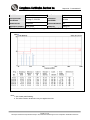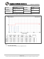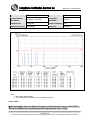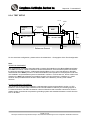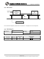
1
Report No.: T120330N01-E CE EMC TEST REPORT for DC-DC Converter MODEL: KHWS SERIES BRAND: DANUBE Test Report Number: T120330N01-E Issued to: Danube Enterprise Co., Ltd. A2, No.255, Fengren Rd., Renwu Dist., Kaohsiung City 81452, Taiwan Issued by: Compliance Certification Services Inc. Tainan Lab. No.8,Jiucengling, Xinhua Dist., Tainan City 712, Taiwan (R.O.C.) TEL: 886-6-5802201 FAX: 886-6-5802202 Issued Date: April 17, 2012 Note: This report shall not be reproduced except in full, without the written approval of Compliance Certification Services Inc. This document may be altered or revised by Compliance Certification Services Inc. personnel only, and shall be noted in the revision section of the document. The client should not use it to claim product endorsement by TAF, NIST or any government agencies. The test results in the report only apply to the tested sample. Page 1 / 57 Report No.: T120330N01-E Revision History Rev. Issue Date Revisions Effect Page Revised By 00 April 17, 2012 Initial Issue ALL Peggy Kuo Page 2 / 57 This report shall not be reproduced except in full, without the written approval of Compliance Certification Services. Report No.: T120330N01-E TABLE OF CONTENTS 1 TEST CERTIFICATION................................................................................................ 4 2 TEST RESULT SUMMARY ......................................................................................... 5 3 EUT DESCRIPTION..................................................................................................... 6 4 TEST METHODOLOGY............................................................................................... 7 4.1. DECISION OF FINAL TEST MODE..................................................................................... 7 4.2. EUT SYSTEM OPERATION ................................................................................................ 7 5 SETUP OF EQUIPMENT UNDER TEST ..................................................................... 8 5.1. DESCRIPTION OF SUPPORT UNITS................................................................................. 8 5.2. CONFIGURATION OF SYSTEM UNDER TEST ................................................................. 8 6 FACILITIES AND ACCREDITATIONS ........................................................................ 9 6.1. FACILITIES .......................................................................................................................... 9 6.2. ACCREDITATIONS ............................................................................................................. 9 6.3. MEASUREMENT UNCERTAINTY..................................................................................... 10 7 EMISSION TEST........................................................................................................ 11 7.1. CONDUCTED EMISSION MEASUREMENT..................................................................... 11 7.2. CONDUCTED EMISSION MEASUREMENT AT TELECOMMUNICATION PORTS......... 14 7.3. RADIATED EMISSION MEASUREMENT.......................................................................... 17 7.4. HARMONICS CURRENT MEASUREMENT...................................................................... 26 7.5. VOLTAGE FLUCTUATION AND FLICKER MEASUREMENT .......................................... 28 8 IMMUNITY TEST ....................................................................................................... 30 8.1. GENERAL DESCRIPTION ................................................................................................ 30 8.2. GENERAL PERFORMANCE CRITERIA DESCRIPTION.................................................. 31 8.3. ELECTROSTATIC DISCHARGE (ESD) ............................................................................ 32 8.4. RADIATED, RADIO-FREQUENCY, ELECTROMAGNETIC FIELD (RS) .......................... 37 8.5. ELECTRICAL FAST TRANSIENT (EFT) ........................................................................... 41 8.6. SURGE IMMUNITY TEST ................................................................................................. 44 8.7. CONDUCTED RADIO FREQUENCY DISTURBANCES (CS)........................................... 47 8.8. POWER FREQUENCY MAGNETIC FIELD ....................................................................... 50 8.9. VOLTAGE DIPS & VOLTAGE INTERRUPTIONS ............................................................. 52 9 PHOTOGRAPHS OF THE TEST CONFIGURATION ................................................ 54 APPENDIX 1 - PHOTOGRAPHS OF EUT..…..…………………………………………………….A1 Page 3 / 57 This report shall not be reproduced except in full, without the written approval of Compliance Certification Services. Report No.: T120330N01-E 1 TEST CERTIFICATION Product: DC-DC Converter Model: KHWS SERIES Brand: DANUBE Applicant: Danube Enterprise Co., Ltd. A2, No.255, Fengren Rd., Renwu Dist., Kaohsiung City 81452, Taiwan (R.O.C) Manufacturer: Danube Enterprise Co., Ltd. A2, No.255, Fengren Rd., Renwu Dist., Kaohsiung City 81452, Taiwan (R.O.C). Tested: March 30, 2012 – April 13, 2012 Applicable EN 55022: 2006 + A1: 2007, Class A Standards: EN 55024:1998+A1:2001+A2:2003 IEC 61000-4-2:2008 IEC 61000-4-3:2006+A1:2007 IEC 61000-4-4:2004 IEC 61000-4-5:2005 IEC 61000-4-6:2008 IEC 61000-4-8:2009 Deviation from Applicable Standard None The above equipment was tested by Compliance Certification Services Inc. for compliance with the requirements of technical standards specified above under the EMC Directive 2004/108/EC.The results of testing in this report apply only to the product/system, which was tested. Other similar equipment will not necessarily produce the same results due to production tolerance and measurement uncertainties. Approved by: Reviewed by: Jeter Wu Assistant Manager Eric Huang Assistant Section Manager Page 4 / 57 This report shall not be reproduced except in full, without the written approval of Compliance Certification Services. Report No.: T120330N01-E 2 TEST RESULT SUMMARY Standard EMISSION Item Result Remarks Conducted (Power Port) N/A No Requirement for DC device Conducted (Telecom Port) N/A No Requirement for DC device Radiated (Below 1GHz) PASS Meet Class A limit Radiated (Above 1GHz) N/A No Requirement Harmonic current emissions N/A No Requirement for DC device Voltage fluctuations & flicker N/A No Requirement for DC device EN 55022: 2006 + A1: 2007 EN 61000-3-2: 2006+A1:2007 EN 61000-3-3: 2008 IMMUNITY【 EN 55024 (1998 + A1: 2001 + A2: 2003) 】 Standard Item Result ESD PASS IEC 61000-4-3:2006+A1:2007 RS PASS IEC 61000-4-4: 2004 EFT PASS IEC 61000-4-5: 2005 Surge PASS IEC 61000-4-6: 2008 CS PASS IEC 61000-4-8:2009 PFMF PASS Voltage dips & voltage variations N/A IEC 61000-4-2: 2008 IEC 61000-4-11: 2004 Remarks Meets the requirements of Performance Criterion A Meets the requirements of Performance Criterion A Meets the requirements of Performance Criterion A Meets the requirements of Performance Criterion A Meets the requirements of Performance Criterion A Meets the requirements of Performance Criterion A No Requirement for DC device Note: 1. The statements of test result on the above are decided by the request of test standard only; the measurement uncertainties are not factored into this compliance determination. 2. The information of measurement uncertainty is available upon the customer’s request. Page 5 / 57 This report shall not be reproduced except in full, without the written approval of Compliance Certification Services. Report No.: T120330N01-E 3 EUT DESCRIPTION Product DC-DC Converter Model KHWS SERIES Brand Name DANUBE Applicant Danube Enterprise Co., Ltd. Manufacture Danube Enterprise Co., Ltd. Housing material Metal Identify Number T120330N01-E Received Date March 30, 2012 For model: KHWS-4815 (I/P:36-75Vdc, O/P:15Vdc/4000mA) EUT Power Source For model: KHWS-1205 (I/P:9-18Vdc, O/P:5Vdc/12000mA) Note: 1. Client consigns only two model samples to test (Model Number: KHWS-4815; KHWS-1205).Therefore, the testing Lab. just guarantees the unit, which has been tested. 2. For more details, please refer to the User’s manual of the EUT PARTNUMBERS STRUCTURE Model Name KHWv-x1x2 ZZZ Difference KH=Series Name W=Wide Input Range v=Type of output voltage (S=single output) x1=Input voltage(9~18V;18~36V;36~75V) x2=Output voltage(3.3~4.5V;5~8.5V;12~14.5V;15~18V;24V ) zzz= 0~9,A~Z or blank for market purpose. EFT/Surge Solution: C1 Electrolytic capacitor 220uF/100V Page 6 / 57 This report shall not be reproduced except in full, without the written approval of Compliance Certification Services. Report No.: T120330N01-E 4 TEST METHODOLOGY 4.1. DECISION OF FINAL TEST MODE The EUT was tested together with the above additional components, and a configuration, which produced the worst emission levels, was selected and recorded in this report. The test configuration/ modes are as the following: Conduction (Power port) Modes: 1. N/A Conduction (Telecom port) Modes 1. N/A Radiation Modes: Full Load 1. 2. KHWS-1205 KHWS-4815 Radiation Modes: (1GHz-6GHz) 1. N/A Immunity Modes: Half Load 1. KHWS-1205 4.2. EUT SYSTEM OPERATION 1. Setup a whole system for test as shown on setup diagram. 2. Turn on power and check function. 3. Start to test by test mode. Page 7 / 57 This report shall not be reproduced except in full, without the written approval of Compliance Certification Services. Report No.: T120330N01-E 5 SETUP OF EQUIPMENT UNDER TEST 5.1. DESCRIPTION OF SUPPORT UNITS The EUT has been tested as an independent unit together with other necessary accessories or support units. The following support units or accessories were used to form a representative test configuration during the tests. Peripherals Devices: No. Product 1 DC power supply No. LOKO DPS-5050 DOC Signal cable Power cable, unshd, 1.6m Signal cable description DC Power Cable A Manufacturer Model No. Certify No. Unshielded, 0.3m, 1pc. Note: 1. All the equipment/cables were placed in the worst-case configuration to maximize the emission during the test. 2. Grounding was established in accordance with the manufacturer’s requirements and conditions for the intended use. 5.2. CONFIGURATION OF SYSTEM UNDER TEST A Load E.U.T. DC power supply AC Source Page 8 / 57 This report shall not be reproduced except in full, without the written approval of Compliance Certification Services. Report No.: T120330N01-E 6 FACILITIES AND ACCREDITATIONS 6.1. FACILITIES All measurement facilities used to collect the measurement data are located at CCS Taiwan Tainan Lab. at No.8,Jiucengling, Xinhua Dist., Tainan City 712, Taiwan (R.O.C.) The sites are constructed in conformance with the requirements of ANSI C63.4 and CISPR Publication 22. All receiving equipment conforms to CISPR 16-1-1, CISPR 16-1-2, CISPR 16-1-3, CISPR 16-1-4 and CISPR 16-1-5. 6.2. ACCREDITATIONS Our laboratories are accredited and approved by the following accreditation body according to ISO/IEC 17025. Taiwan TAF The measuring facility of laboratories has been authorized or registered by the following approval agencies. Canada Industry Canada Germany TUV NORD Taiwan BSMI USA FCC Copies of granted accreditation certificates are available for downloading from our web site, http://www.ccsrf.com Page 9 / 57 This report shall not be reproduced except in full, without the written approval of Compliance Certification Services. Report No.: T120330N01-E 6.3. MEASUREMENT UNCERTAINTY Where relevant, the following measurement uncertainty levels have been estimated for tests performed on the EUT as specified in CISPR 16-4-2: Measurement Frequency Uncertainty Power Line Conducted Emission 9kHz~30MHz ±2.90dB Conduction Emission 150kHz~30MHz ±3.31dB 30 MHz ~200 MHz ±3.76dB 200 MHz ~1000 MHz ±3.73dB 30 MHz ~200 MHz ±3.60dB 200 MHz ~1000 MHz ±3.70dB 30 MHz ~200 MHz ±3.99dB 200 MHz ~1000 MHz ±3.31dB 30 MHz ~200 MHz ±3.38dB 200 MHz ~1000 MHz ±3.27dB 30 MHz ~200 MHz ±3.59dB 200 MHz ~1000 MHz ±3.27dB 1000 MHz ~6000 MHz ±3.20dB Test Site : OATS-5 Radiated Emission (10m) Test Site : OATS-6 Test Site : OATS-7 Test Site : OATS-5 Radiated Emission (3m) Test Site : OATS-6 Test Site : OATS-6 This uncertainty represents an expanded uncertainty expressed at approximately the 95% confidence level using a coverage factor of k=2. Consistent with industry standard (e.g. CISPR 22: 2005, clause 11, Measurement Uncertainty) determining compliance with the limits shall be base on the results of the compliance measurement. Consequently the measure emissions being less than the maximum allowed emission result in this be a compliant test or passing test. The acceptable measurement uncertainty value without requiring revision of the compliance statement is base on conducted and radiated emissions being less than UCISPR which is 3.6dB and 5.2dB respectively. CCS values (called ULab in CISPR 16-4-2) is less than UCISPR as shown in the table above. Therefore, MU need not be considered for compliance. Page 10 / 57 This report shall not be reproduced except in full, without the written approval of Compliance Certification Services. Report No.: T120330N01-E 7 EMISSION TEST 7.1. CONDUCTED EMISSION MEASUREMENT 7.1.1. LIMITS Class A (dBuV) Class B (dBuV) FREQUENCY (MHz) Quasi-peak Average Quasi-peak Average 0.15 - 0.5 79 66 66 - 56 56 - 46 0.50 - 5.0 73 60 56 46 5.0 - 30.0 73 60 60 50 Note: 1. The lower limit shall apply at the transition frequencies. 2. The limit decreases in line with the logarithm of the frequency in the range of 0.15 to 0.50 MHz. 3. All emanations from a class A/B digital device or system, including any network of conductors and apparatus connected thereto, shall not exceed the level of field strengths specified above. 7.1.2. TEST INSTRUMENTS Conducted Emission room # 1 Name of Equipment Manufacturer Model Serial Number Calibration Due SCHWARZBECK NNLK 8130 8130124 Sep. 25, 2012 Rohde & Schwarz ESH 3-Z5 840062/021 Aug. 02, 2012 Rohde & Schwarz ESCS 30 100348 JUL. 03, 2012 CCS BNC50 11 OCT. 30, 2012 L.I.S.N. TEST RECEIVER BNC COAXIAL CABLE Test S/W e-3 (5.04211c) R&S (2.27) Note: The calibration interval of the above test instruments is 12 months and the calibrations are traceable to NML/ROC and NIST/USA. Page 11 / 57 This report shall not be reproduced except in full, without the written approval of Compliance Certification Services. Report No.: T120330N01-E 7.1.3. TEST PROCEDURES Procedure of Preliminary Test The EUT and Support equipment, if needed, was set up as per the test configuration to simulate typical usage per the user’s manual. When the EUT is a tabletop system, a wooden table with a height of 0.8 meters is used and is placed on the ground plane as per EN 55022 (see Test Facility for the dimensions of the ground plane used). When the EUT is a floor standing equipment, it is placed on the ground plane, which has a 15 cm non-conductive covering to insulate the EUT from the ground plane. All I/O cables were positioned to simulate typical actual usage as per EN 55022. The test equipment EUT installed received main power, through a Line Impedance Stabilization Network (LISN), which supplied power source and was grounded to the ground plane. All support equipment power received from a second LISN. The EUT test program was started. Emissions were measured on each current carrying line of the EUT using an EMI Test Receiver connected to the LISN powering the EUT. The Receiver scanned from 150kHz to 30MHz for emissions in each of the test modes. During the above scans, the emissions were maximized by cable manipulation. The test mode(s) described in Item 4.1 were scanned during the preliminary test. After the preliminary scan, we found the test mode described in Item 4.1 producing the highest emission level. The EUT configuration and cable configuration of the above highest emission levels were recorded for reference of the final test. Procedure of Final Test EUT and support equipment were set up on the test bench as per the configuration with highest emission level in the preliminary test. A scan was taken on both power lines, Line 1 and Line 2, recording at least the six highest emissions. Emission frequency and amplitude were recorded into a computer in which correction factors were used to calculate the emission level and compare reading to the applicable limit. The test data of the worst-case condition(s) was recorded. Page 12 / 57 This report shall not be reproduced except in full, without the written approval of Compliance Certification Services. Report No.: T120330N01-E 7.1.4. TEST SETUP Vertical Reference 40 cm EMI Test Receiver EUT 8 80 cm LISN Reference Ground Plan For the actual test configuration, please refer to the related item – Photographs of the Test Configuration. 7.1.5. DATA SAMPLE Freq. (MHz) LISN Factor (dB) Cable Loss (dB) Meter Reading (dBuV) Measured Level (dBuV) Limits (dBuV) Over Limits (dBuV) Detector x.xx 9.6 0.1 15.7 25.4 46 -20.6 QP Freq. . LISN Factor .. Cable Loss Meter Reading Measured Level Limit .. Over Limit Peak QP AV = Emission frequency in MHz = Insertion loss of LISN and Pulse Limiter = Insertion loss of Cable (LISN to EMI Tester Receiver) = Uncorrected Analyzer/Receiver reading = Read Level + Factor = Limit stated in standard = Reading in reference to limit = Peak Reading = Quasi-peak Reading = Average Reading Calculation Formula 1. Measured Level (dBuV) = LISN Factor (dB) + Cable Loss (dB)+ Meter Reading (dBuV) 2. Over Limit (dBuV) = Measured Level (dBuV) – Limits (dBuV) 7.1.6. TEST RESULTS ※ Since the EUT is powered by DC source , this test item is not applicable. Page 13 / 57 This report shall not be reproduced except in full, without the written approval of Compliance Certification Services. Report No.: T120330N01-E 7.2. CONDUCTED EMISSION MEASUREMENT AT TELECOMMUNICATION PORTS 7.2.1. LIMITS For Class A Equipment Voltage Limit (dBuV) Current Limit (dBuA) FREQUENCY (MHz) Quasi-peak Average Quasi-peak Average 0.15 ~ 0.5 97 ~ 87 84 ~ 74 53 ~ 43 40 ~ 30 0.5 ~ 30.0 87 74 43 30 Note: The limits decrease linearly with the logarithm of the frequency in the range 0.15 MHz to 0.5 MHz. For Class B Equipment Voltage Limit (dBuV) Current Limit (dBuA) FREQUENCY (MHz) Quasi-peak Average Quasi-peak Average 0.15 - 0.5 84 ~ 74 74 ~ 64 40 ~ 30 30 ~ 20 0.5 - 30.0 74 64 30 20 Note: The limits decrease linearly with the logarithm of the frequency in the range 0.15 MHz to 0.5 MHz. 7.2.2. TEST INSTRUMENTS Conducted Emission room # 1 Name of Equipment Manufacturer Model Serial Number Calibration Due SCHWARZBECK NNLK 8130 8130124 Sep. 25, 2012 Rohde & Schwarz ESH 3-Z5 840062/021 Aug. 02, 2012 TEST RECEIVER Rohde & Schwarz ESCS 30 100348 JUL. 03, 2012 BNC COAXIAL CABLE CCS BNC50 11 OCT. 30, 2012 ISN FCC F-071115-1057-1-09 111130 Sep.01, 2012 L.I.S.N. Test S/W e-3 (5.04211c) R&S (2.27) Note: 1. The calibration interval of the above test instruments is 12 months and the calibrations are traceable to NML/ROC and NIST/USA. 2. N.C.R = No Calibration Request. Page 14 / 57 This report shall not be reproduced except in full, without the written approval of Compliance Certification Services. Report No.: T120330N01-E 7.2.3. TEST PROCEDURE Selecting ISN for unscreened cable or a current probe for screened cable to take measurement. The port of the EUT was connected to the remote side support equipment through the ISN/Current Probe and communication in normal condition. Making a overall range scan by using the test receiver controlled by controller and record at least six highest emissions for showing in the test report. Emission frequency and amplitude were recorded into a computer in which correction factors were used to calculate the emission level and compare reading to the applicable limit. In case of measuring on the screened cable, the current limit shall be applied; otherwise the voltage limit should be applied. The following test modes was scanned during the preliminary test: N/A After the preliminary scan, we found the following test mode(s) producing the highest emission level and test data of the worst case was recorded. N/A 7.2.4. TEST SETUP For the actual test configuration, please refer to the related item – Photographs of the Test Configuration. Page 15 / 57 This report shall not be reproduced except in full, without the written approval of Compliance Certification Services. Report No.: T120330N01-E 7.2.5. DATA SAMPLE Freq. (MHz) LISN Factor dB Cable Loss dB Meter Reading dBuV Measured Level dBuV Limits x.xx 9.71 0.02 37.17 46.9 Freq. LISN Factor Cable loss Meter Reading Measured Level Limit Over Limit Peak QP AV Detector dBuV Over Limits dBuV 66 -19.10 QP = Emission frequency in MHz = Insertion loss of ISN and Pulse Limiter = Insertion loss of Cable (ISN to EMI Tester Receiver) = Uncorrected Analyzer/Receiver reading = Read Level + Factor = Limit stated in standard = Reading in reference to limit = Peak Reading = Quasi-peak Reading = Average Reading Calculation Formula Over Limit (dB) = Level (dBuV) – Limit (dBuV) 7.2.6. TEST RESULTS ※Note: No applicable, the EUT doesn’t have LAN Port or Modem port. Page 16 / 57 This report shall not be reproduced except in full, without the written approval of Compliance Certification Services. Report No.: T120330N01-E 7.3. RADIATED EMISSION MEASUREMENT 7.3.1. LIMITS Below 1GHz dBuV/m (At 10m) FREQUENCY (MHz) Class A Class B 30 ~ 230 40 30 230 ~ 1000 47 37 Note: The lower limit shall apply at the transition frequencies. Above 1GHz Class A (dBuV/m) (At 3m) Class B (dBuV/m) (At 3m) Average Peak Average Peak 1000 ~ 3000 56 76 50 70 3000 ~ 6000 60 80 54 74 FREQUENCY (MHz) Note: The lower limit shall apply at the transition frequencies. According to EN55022: 2006 + A1: 2007 clause 6.2, the measurement frequency range shown in the following table: Highest frequency generated or used within the EUT Upper frequency of measurement range or on which the EUT operates or tunes (MHz) (MHz) Less than 108 1000 108-500 2000 500-1000 5000 Above 1000 5 times of the highest frequency or 6GHz, whichever is less Page 17 / 57 This report shall not be reproduced except in full, without the written approval of Compliance Certification Services. Report No.: T120330N01-E 7.3.2. TEST INSTRUMENTS Open Area Test Site # 7 Model Serial Number Calibration Due Rohde & Schwarz ESCS30 100343 FEB. 14, 2013 SUHNER RG_214_U/2X 7 NOV. 24, 2012 Sunol sciences JB1 A013105-1 OCT. 05, 2012 Name of Equipment Manufacturer TEST RECEIVER TYPE N COAXIAL CABLE BILOG ANTENNA Test Software EMI e-3 / AUDIX (5.04211c) Above 1GHz Used RF Cable SUHNER SUCOFLEX104PEA 20520/4PEA NOV. 10, 2012 Horn Antenna Com-Power AH-118 071032 DEC. 27, 2012 Spectrum Analyzer R&S FSEK 30 835253/002 Sep,29,2012 Pre-Amplifier MITEQ AFS44-00108650-42-10P-44 1205908 NOV. 23, 2012 Turn Table Yo Chen 001 ---------- N.C.R. Antenna Tower AR TP1000A 309874 N.C.R. Controller CT SC101 ---------- N.C.R. ERS-180A EC1204141 N.C.R RF Swicth Test Software E-INSTRUMENT TELH LTD e-3 (5.04303e) Note: 1. 2. The calibration interval of the above test instruments is 12 months and the calibrations are traceable to NML/ROC and NIST/USA. N.C.R. = No Calibration Request. Page 18 / 57 This report shall not be reproduced except in full, without the written approval of Compliance Certification Services. Report No.: T120330N01-E 7.3.3. TEST PROCEDURE Procedure of Preliminary Test The equipment was set up as per the test configuration to simulate typical usage per the user’s manual. When the EUT is a tabletop system, a wooden turntable with a height of 0.8 meters is used which is placed on the ground plane. When the EUT is a floor standing equipment, it is placed on the ground plane which has a 15 cm non-conductive covering to insulate the EUT from the ground plane. Support equipment, if needed, was placed as per EN 55022. All I/O cables were positioned to simulate typical usage as per EN 55022. The EUT received power source from the outlet socket under the turntable. All support equipment power received from another socket under the turntable. The antenna was placed at 10/3 meter away from the EUT as stated in EN 55022. The antenna connected to the Spectrum Analyzer via a cable and at times a pre-amplifier would be used. The Analyzer / Receiver quickly scanned from 30MHz to 6000MHz. The EUT test program was started. Emissions were scanned and measured rotating the EUT to 360 degrees and positioning the antenna 1 to 4 meters above the ground plane, in both the vertical and the horizontal polarization, to maximize the emission reading level. The test mode(s) described in Item 4.1 were scanned during the preliminary test: After the preliminary scan, we found the test mode described in Item 4.1 producing the highest emission level. The EUT and cable configuration, antenna position, polarization and turntable position of the above highest emission level were recorded for the final test. Procedure of Final Test EUT and support equipment were set up on the turntable as per the configuration with highest emission level in the preliminary test. The Analyzer / Receiver scanned from 30MHz to 6000MHz. Emissions were scanned and measured rotating the EUT to 360 degrees, varying cable placement and positioning the antenna 1 to 4 meters above the ground plane, in both the vertical and the horizontal polarization, to maximize the emission reading level. Recorded at least the six highest emissions. Emission frequency, amplitude, antenna position, polarization and turntable position were recorded into a computer in which correction factors were used to calculate the emission level and compare reading to the applicable limit and only Q.P. reading is presented. The test data of the worst-case condition(s) was recorded. Page 19 / 57 This report shall not be reproduced except in full, without the written approval of Compliance Certification Services. Report No.: T120330N01-E 7.3.4. TEST SETUP Below 1GHz Test table & Turntable 1m ~ 4m EUT Coaxial Cable Power Cable 0.8 m 10 m or 3 m Filter Ground Plane To Power Source EMI Receiver For the actual test configuration, please refer to the related item – Photographs of the Test Configuration. Above 1GHz Page 20 / 57 This report shall not be reproduced except in full, without the written approval of Compliance Certification Services. Report No.: T120330N01-E 7.3.5. DATA SAMPLE Reading Freq. (MHz) x.xx dBuV/m Antenna Factor dB Cable loss dB Measure level dBuV/m dBuV/m 24.48 7.33 1.50 33.31 40 Freq. Reading Antenna Factor Cable loss Measure level Limit Over limit Peak QP AV Limit Over Detector limit dBuV/m -6.69 QP = Emission frequency in MHz = Uncorrected Analyzer/Receiver reading = Antenna Factor = Insertion loss of cable = Reading + Factor = Limit stated in standard = Measure level – Limit = Peak Reading = Quasi-peak Reading = Average Reading Calculation Formula Over limit (dBuV/m) = Result (dBuV/m) – Limit (dBuV/m) Above 1GHz Freq. Reading AF C_loss Pre-amp (MHz) (dBμV) (dBμV) (dB) (dB) (dB) (dBμV/m) (dBμV/m) XXXX. XX 56.00 25.14 2.07 41.77 0.72 Freq. Reading AF C_loss Pre-amp Filter Level Limit Margin Mark: = Emission frequency in MHz = Uncorrected Analyzer/Receiver reading = Antenna Factor = Insertion loss of cable = Pre-amplifier Gain = Insertion loss of filter = Readind+AF+Closs-Pre-amp+Fliter = Limit stated in standard = Reading in reference to limit P = Peak Reading Q = Quasi-peak Reading A = Average Reading .. Filter Level 42.16 Limit 70.00 Margin Mark (dB) (P/Q/A) -27.84 P Calculation Formula Margin (dB) =Level (dBuV/m) – Limit (dBuV/m) Page 21 / 57 This report shall not be reproduced except in full, without the written approval of Compliance Certification Services. Report No.: T120330N01-E 7.3.6. TEST RESULTS Below 1GHz Model No. KHWS-4815 Test Mode Full Load Environmental Conditions 24.9deg.C, 52% RH Resolution Bandwidth 120 kHz Antenna Pole Vertical Antenna Distance 10m Detector Function Quasi-peak. Tested by Shiang Su (The chart below shows the highest readings taken from the final data.) Note: 1. QP= Quasi-peak Reading. 2. The other emission levels were very low against the limit. Page 22 / 57 This report shall not be reproduced except in full, without the written approval of Compliance Certification Services. Report No.: T120330N01-E Model No. KHWS-4815 Test Mode Full Load Environmental Conditions 24.9deg.C, 52% RH Resolution Bandwidth 120 kHz Antenna Pole Horizontal Antenna Distance 10m Detector Function Quasi-peak. Tested by Shiang Su (The chart below shows the highest readings taken from the final data.) Note: 1. QP= Quasi-peak Reading. 2. The other emission levels were very low against the limit. Page 23 / 57 This report shall not be reproduced except in full, without the written approval of Compliance Certification Services. Report No.: T120330N01-E Model No. KHWS-1205 Test Mode Full Load Environmental Conditions 24.9deg.C, 52% RH Resolution Bandwidth 120 kHz Antenna Pole Vertical Antenna Distance 10m Detector Function Quasi-peak. Tested by Shiang Su (The chart below shows the highest readings taken from the final data.) Note: 1. QP= Quasi-peak Reading. 2. The other emission levels were very low against the limit. Page 24 / 57 This report shall not be reproduced except in full, without the written approval of Compliance Certification Services. Report No.: T120330N01-E Model No. KHWS-1205 Test Mode Full Load Environmental Conditions 24.9deg.C, 52% RH Resolution Bandwidth 120 kHz Antenna Pole Horizontal Antenna Distance 10m Detector Function Quasi-peak. Tested by Shiang Su (The chart below shows the highest readings taken from the final data.) Note: 1. QP= Quasi-peak Reading. 2. The other emission levels were very low against the limit. Above 1GHz ※ No applicable, since the highest frequency of the internal sources of the EUT is less than 108MHz, the measurement shall only be made up to 1 GHz. Page 25 / 57 This report shall not be reproduced except in full, without the written approval of Compliance Certification Services. Report No.: T120330N01-E 7.4. HARMONICS CURRENT MEASUREMENT 7.4.1. LIMITS OF HARMONICS CURRENT MEASUREMENT Limits for Class A equipment Harmonics Max. permissible Order harmonics current n A Odd harmonics 3 2.30 5 1.14 7 0.77 9 0.40 11 0.33 13 0.21 15<=n<=39 0.15x15/n Even harmonics 2 1.08 4 0.43 6 0.30 8<=n<=40 0.23x8/n Harmonics Order n 3 5 7 9 11 13 15<=n<=39 Limits for Class D equipment Max. permissible Max. permissible harmonics harmonics current current per watt mA/W A Odd Harmonics only 3.4 2.30 1.9 1.14 1.0 0.77 0.5 0.40 0.35 0.33 0.30 0.21 3.85/n 0.15x15/n Note: 1. Class A and Class D are classified according to item 7.4.3. 2. According to section 7 of EN 61000-3-2, the above limits for all equipment except for lighting equipment having an active input power > 75 W and no limits apply for equipment with an active input power up to and including 75 W. 7.4.2. TEST INSTRUMENTS Name of Equipment Manufacturer Model Serial Number Calibration Due Harmonics Analyzer TTI HA1600 198202 APR. 11, 2013 Test S/W Note: H/F HA 1600 PC LINK Field Probe The calibration interval of the above test instruments is 12 months and the calibrations are traceable to NML/ROC and NIST/USA. Page 26 / 57 This report shall not be reproduced except in full, without the written approval of Compliance Certification Services. Report No.: T120330N01-E 7.4.3. TEST PROCEDURE The EUT was placed on the top of a wooden table 0.8 meters above the ground and operated to produce the maximum harmonic components under normal operating conditions for each successive harmonic component in turn. The classification of EUT is according to section 5 of EN 61000-3-2. The EUT is classified as follows: Class A: Balanced three-phase equipment, Household appliances excluding equipment as Class D, Tools excluding portable tools, Dimmers for incandescent lamps, audio equipment, equipment not specified in one of the three other classes. Class B: Portable tools; Arc welding equipment which is not professional equipment. Class C: Lighting equipment. Class D: Equipment having a specified power less than or equal to 600 W of the following types: Personal computers and personal computer monitors and television receivers. The correspondent test program of test instrument to measure the current harmonics emanated from EUT is chosen. The measure time shall be not less than the time necessary for the EUT to be exercised. 7.4.4. TEST SETUP Harmonic & Flicker Analyzer + Power Source Power Cord EUT Support Units 0.8m For the actual test configuration, please refer to the related item – Photographs of the Test Configuration. 7.4.5. TEST RESULTS Power Consumption --W Test Results Environmental Conditions - deg.C, - % RH, - mbar Limits Test Mode --- Tested by --Class A B C D --- Note: 1. Limits classified according to item 7.4.3. 2. According to clause 7 of EN 61000-3-2: 2006, equipment with a rated power of 75W or less, no limits apply. The test result is only for reference. Test result of EN 61000-3-2 ※ Since the EUT is powered by DC source , this test item is not applicable. Page 27 / 57 This report shall not be reproduced except in full, without the written approval of Compliance Certification Services. Report No.: T120330N01-E 7.5. VOLTAGE FLUCTUATION AND FLICKER MEASUREMENT 7.5.1. LIMITS OF VOLTAGE FLUCTUATION AND FLICKER MEASUREMENT TEST ITEM LIMIT REMARK Pst 1.0 Pst means short-term flicker indicator. Plt 0.65 Plt means long-term flicker indicator. Tdt (ms) 500 Tdt means maximum time that dt exceeds 3 %. dmax (%) 4% dmax means maximum relative voltage change. dc (%) 3.3% dc means relative steady-state voltage change 7.5.2. TEST INSTRUMENTS IMMUNITY SHIELDED ROOM Name of Equipment Manufacturer Model Serial Number Calibration Due Harmonics Analyzer TTI HA1600 198202 APR. 11, 2013 Test S/W H/F HA 1600 PC LINK Field Probe Note: The calibration interval of the above test instruments is 12 months and the calibrations are traceable to NML/ROC and NIST/USA. 7.5.3. TEST PROCEDURE The EUT was placed on the top of a wooden table 0.8 meters above the ground and operated to produce the most unfavorable sequence of voltage changes under normal operating conditions. During the flick measurement, the measure time shall include that part of whole operation cycle in which the EUT produce the most unfavorable sequence of voltage changes. The observation period for short-term flicker indicator is 10 minutes and the observation period for long-term flicker indicator is 2 hours. Page 28 / 57 This report shall not be reproduced except in full, without the written approval of Compliance Certification Services. Report No.: T120330N01-E 7.5.4. TEST SETUP Harmonics & Flicker Analyzer+ Power Source Power Cord EUT Support Units 0.8m For the actual test configuration, please refer to the related item – Photographs of the Test Configuration. 7.5.5. TEST RESULTS N/A Test Mode N/A Environmental Conditions N/A Tested by N/A Observation Period (Tp) Test result of EN 61000-3-3 ※ Since the EUT is powered by DC source , this test item is not applicable. Page 29 / 57 This report shall not be reproduced except in full, without the written approval of Compliance Certification Services. Report No.: T120330N01-E 8 IMMUNITY TEST 8.1. GENERAL DESCRIPTION EN 55024: 1998 + A1: 2001 + A2: 2003 Product Standard Test Type Minimum Requirement IEC 61000-4-2 Electrostatic Discharge – ESD: 8KV air discharge, 4kV Contact discharge, Performance Criterion B IEC 61000-4-3 Radio-Frequency Electromagnetic Field Susceptibility Test – RS: 80 ~1000 MHz, 3V/m, 80% AM(1kHz), Performance Criterion A IEC 61000-4-4 Electrical Fast Transient/Burst - EFT, AC Power Port: 1kV DC Power Port: 0.5kV Signal Ports and Telecommunication Ports: 0.5kV Performance Criterion B Basic Standard, Specification, and IEC 61000-4-5 Performance Criterion required Surge Immunity Test: 1.2/50 us Open Circuit Voltage, 8/20 us Short Circuit Current, AC Power Port ~ line to line: 1kV, line to earth (ground): 2kV DC Power Port ~ line to line: 0.5kV Signal and Telecommunication Ports ~ line to ground: 1kV Performance Criterion B IEC 61000-4-6 Conducted Radio Frequency Disturbances Test –CS: 0.15 ~ 80 MHz, 3Vrms, 80% AM, 1kHz, Performance Criterion A IEC 61000-4-8 Power frequency magnetic field immunity test 50 Hz, 1A/m Performance Criterion A IEC 61000-4-11 Voltage Dips: i) >95% reduction for 0.5 periods, Performance Criterion B ii) 30% reduction for 25 periods, Performance Criterion C Voltage Interruptions: >95% reduction for 250 periods Performance Criterion C Page 30 / 57 This report shall not be reproduced except in full, without the written approval of Compliance Certification Services. Report No.: T120330N01-E 8.2. GENERAL PERFORMANCE CRITERIA DESCRIPTION Criteria A: The apparatus shell continues to operate as intended without operator intervention. No degradation of performance or loss of function is allowed below a performance level specified by the manufacturer, when the apparatus is used as intended. The performance level may be replaced by a permissible loss of performance. If the manufacturer does not specify the minimum performance level or the permissible performance loss, then either of these may be derived from the product description and documentation, and by what the user may reasonably expect from the equipment if used as intended. After test, the apparatus shell continues to operate as intended without operator intervention. No degradation of performance or loss of function is allowed, after the application of the phenomenon below a performance level specified by the manufacturer, when the apparatus is used as intended. The performance level may be replaced by a permissible loss of performance. Criteria B: Criteria C: During the test, degradation of performance is however allowed. However, no change of operating state if stored data is allowed to persist after the test. If the manufacturer does not specify the minimum performance level or the permissible performance loss, then either of these may be derived from the product description and documentation, and by what the user may reasonably expect from the equipment if used as intended. Temporary loss of function is allowed, provided the functions is self-recoverable or can be restored by the operation of controls by the user in accordance with the manufacturer instructions. Functions, and/or information stored in non-volatile memory, or protected by a battery backup, shall not be lost. Page 31 / 57 This report shall not be reproduced except in full, without the written approval of Compliance Certification Services. Report No.: T120330N01-E 8.3. ELECTROSTATIC DISCHARGE (ESD) 8.3.1. TEST SPECIFICATION Basic Standard: Discharge Impedance: Discharge Voltage: Polarity: Number of Discharge: Discharge Mode: IEC 61000-4-2 330 ohm / 150 pF Air Discharge: N/A Contact Discharge: 4 kV (Direct) Positive & Negative Air Discharge: min. 10 times at each test point for each polarity Contact Discharge: min. 200 times in total Single Discharge 1 second minimum 8.3.2. TEST INSTRUMENT IMMUNITY SHIELDED ROOM Name of Equipment Manufacturer Model Serial Number Calibration Due ESD Simulator NoiseKen ESS-2002 ESS04Z3762 FEB. 16, 2013 Note: The calibration interval of the above test instruments is 12 months and the calibrations are traceable to NML/ROC and NIST/USA. Page 32 / 57 This report shall not be reproduced except in full, without the written approval of Compliance Certification Services. Report No.: T120330N01-E 8.3.3. TEST PROCEDURE The discharges shall be applied in two ways: a) Contact discharges to the conductive surfaces and coupling planes: The EUT shall be exposed to at least 200 discharges, 100 each at negative and positive polarity, at a minimum of four test points. One of the test points shall be subjected to at least 50 indirect discharges to the center of the front edge of the Horizontal Coupling Plane (HCP). The remaining three test points shall each receive at least 50 direct contact discharges. If no direct contact test points are available, then at least 200 indirect discharges shall be applied in the indirect mode. Test shall be performed at a maximum repetition rate of one discharge per second. b) Air discharges at slots and apertures and insulating surfaces: On those parts of the EUT where it is not possible to perform contact discharge testing, the equipment should be investigated to identify user accessible points where breakdown may occur. Such points are tested using the air discharge method. This investigation should be restricted to those area normally handled by the user. A minimum of 10 single air discharges shall be applied to the selected test point for each such area. The basic test procedure was in accordance with IEC 61000-4-2: a) The EUT was located 0.1 m minimum from all side of the HCP (dimensions 1.6m x 0.8m). b) The support units were located another table 30 cm away from the EUT, but direct support unit was/were located at same location as EUT on the HCP and keep at a distance of 10 cm with EUT. c) The time interval between two successive single discharges was at least 1 second. d) Contact discharges were applied to the non-insulating coating, with the pointed tip of the generator penetrating the coating and contacting the conducting substrate. e) Air discharges were applied with the round discharge tip of the discharge electrode approaching the EUT as fast as possible (without causing mechanical damage) to touch the EUT. After each discharge, the ESD generator was removed from the EUT and re-triggered for a new single discharge. The test was repeated until all discharges were complete. f) At least ten single discharges (in the most sensitive polarity) were applied at the front edge of each HCP opposite the center point of each unit of the EUT and 0.1 meters from the front of the EUT. The long axis of the discharge electrode was in the plane of the HCP and perpendicular to its front edge during the discharge. g) At least ten single discharges (in the most sensitive polarity) were applied to the center of one vertical edge of the Vertical Coupling Plane (VCP) in sufficiently different positions that the four faces of the EUT were completely illuminated. The VCP (dimensions 0.5m x 0.5m) was placed vertically to and 0.1 meters from the EUT. Page 33 / 57 This report shall not be reproduced except in full, without the written approval of Compliance Certification Services. Report No.: T120330N01-E 8.3.4. TEST SETUP 10 cm Support units R 0.5 mm Thick Insulator EUT R R 30 cm Wooden Table 桌 VCP HCP Wooden Table 0.8 m R R R R =470 kΩ Reference Ground For the actual test configuration, please refer to the related item – Photographs of the Test Configuration. Note: TABLETOP EQUIPMENT The configuration consisted of a wooden table 0.8 meters high standing on the Ground Reference Plane. The GRP consisted of a sheet of aluminum at least 0.25mm thick, and 2.5 meters square connected to the protective grounding system. A Horizontal Coupling Plane (1.6m x 0.8m) was placed on the table and attached to the GRP by means of a cable with 940kohm total impedance. The equipment under test, was installed in a representative system as described in section 7 of IEC 61000-4-2, and its cables were placed on the HCP and isolated by an insulating support of 0.5mm thickness. A distance of 1-meter minimum was provided between the EUT and the walls of the laboratory and any other metallic structure. FLOOR-STANDING EQUIPMENT The equipment under test was installed in a representative system as described in section 7 of IEC 61000-4-2, and its cables were isolated from the Ground Reference Plane by an insulating support of 0.1-meter thickness. The GRP consisted of a sheet of aluminum that is at least 0.25mm thick, and 2.5 meters square connected to the protective grounding system and extended at least 0.5 meters from the EUT on all sides. Page 34 / 57 This report shall not be reproduced except in full, without the written approval of Compliance Certification Services. Report No.: T120330N01-E 8.3.5. TEST RESULTS Temperature 25oC Humidity 43% RH Pressure 1028mbar Tested By Rock Guo Required Passing Performance Criterion B Air Discharge Test Levels Test Points ± 2 kV ± 4 kV ± 8 kV Pass Fail Front Back Left Right Top Bottom Results Performance Criterion A B A B A B A B A B A B Observation Contact Discharge Test Levels Test Points ± 2 kV ± 4 kV ± 6 kV Pass Front Back Left Right Top Bottom Side of EUT Front Back Left Right Side of EUT Front Back Left Right Fail Results Performance Criterion A B A B A B A B A B A B Discharge To Horizontal Coupling Plane Test Levels Results Performance Pass Fail ± 2 kV ± 4 kV ± 6 kV Criterion A B A B A B A B Discharge To Vertical Coupling Plane Test Levels Results Performance Pass Fail ± 2 kV ± 4 kV ± 6 kV Criterion A B A B A B A B Observation Observation Observation Page 35 / 57 This report shall not be reproduced except in full, without the written approval of Compliance Certification Services. Report No.: T120330N01-E The Photo for Discharge Points of EUT ‘C’ Mark — Contact Discharged Page 36 / 57 This report shall not be reproduced except in full, without the written approval of Compliance Certification Services. Report No.: T120330N01-E 8.4. RADIATED, RADIO-FREQUENCY, ELECTROMAGNETIC FIELD (RS) 8.4.1. TEST SPECIFICATION Basic Standard: Frequency Range: Field Strength: Modulation: Frequency Step: Polarity of Antenna: Test Distance: Antenna Height: IEC 61000-4-3 80 MHz ~1000 MHz 3 V/m 1kHz Sine Wave, 80%, AM Modulation 1 % of preceding frequency value Horizontal and Vertical 3m 1.5m 8.4.2. TEST INSTRUMENT 966 RS Chamber Name of Equipment Manufacturer Model Serial Number Calibration Due Computer SYNNEX BTO –LMIW300 – GB A41202-0031 N.C.R. LCD Monitor Acer AL1715sm ETL130719944302366RH01 N.C.R. Keyboard SYNNEX 5211A G4430091266 N.C.R. Amplifier Freq. Range :80MHz~1GHz AR 150W1000M3 310037 N.C.R. AR 60S1G3M3 310102 N.C.R. HP ESG-D3000A US36260655 DEC. 27, 2012 BOONTON 4232A-01-02 122202 DEC. 28, 2012 AR AT5080 309817 N.C.R. HP 8920A 3412A04298 DEC. 28, 2012 Amplifier Freq. Range :0.8~3GHz Digital SIGNAL GENERATOR RF Power Meter Log – Periodic Antenna RF Communications test set Test S/W RS SW1005 R1_4 Note: 1. The calibration interval of the above test instruments is 12 months and the calibrations are traceable to NML/ROC and NIST/USA. 2. N.C.R.= No Calibration required Page 37 / 57 This report shall not be reproduced except in full, without the written approval of Compliance Certification Services. Report No.: T120330N01-E 8.4.3. TEST PROCEDURE The test procedure was in accordance with IEC 61000-4-3 a) The testing was performed in a fully anechoic chamber. The transmit antenna was located at a distance of 3 meters from the EUT. b) The frequency range is swept from 80 MHz to 1000 MHz, with the signal 80% amplitude modulated with a 1kHz sine-wave. The rate of sweep did not exceed 1.5 x 10 -3 decade/s, where the frequency range is swept incrementally, the step size was 1% of preceding frequency value. c) The dwell time at each frequency shall be not less than the time necessary for the EUT to be able to respond. d) The test was performed with the EUT exposed to both vertically and horizontally polarized fields on each of the four sides. Page 38 / 57 This report shall not be reproduced except in full, without the written approval of Compliance Certification Services. Report No.: T120330N01-E 8.4.4. TEST SETUP 3 meter RS Chamber EUT & Support Units 1.5 meter 0.8m Power Amp Signal Generator PC Controller to control S.G. & PA as well as forward power EUT Monitoring by using a camera Control Room For the actual test configuration, please refer to the related item – Photographs of the Test Configuration. Note: TABLETOP EQUIPMENT The EUT installed in a representative system as described in section 7 of IEC 61000-4-3 was placed on a non-conductive table 0.8 meters in height. The system under test was connected to the power and signal wire according to relevant installation instructions. FLOOR-STANDING EQUIPMENT The EUT installed in a representative system as described in section 7 of IEC 61000-4-3 was placed on a non-conductive wood support 0.1 meters in height. The system under test was connected to the power and signal wire according to relevant installation instructions. Page 39 / 57 This report shall not be reproduced except in full, without the written approval of Compliance Certification Services. Report No.: T120330N01-E 8.4.5. TEST RESULTS Temperature 26oC Humidity 50% RH Pressure 1028mbar Dwell Time 3 sec. Tested By Ted Huang Required Passing Performance Criterion A Frequency (MHz) Polarity Azimuth Field Strength (V/m) 80 ~ 1000 V&H 0 3 A B 80 ~ 1000 V&H 90 3 A B 80 ~ 1000 V&H 180 3 A B 80 ~ 1000 V&H 270 3 A B Performance Criterion Page 40 / 57 This report shall not be reproduced except in full, without the written approval of Compliance Certification Services. Report No.: T120330N01-E 8.5. ELECTRICAL FAST TRANSIENT (EFT) 8.5.1. TEST SPECIFICATION Basic Standard: Test Voltage: Polarity: Impulse Frequency: Impulse Wave-shape: Burst Duration: Burst Period: Test Duration: IEC 61000-4-4 AC Power Port: 1.0kV DC Power Port: 0.5kV Signal Ports and Telecommunication Ports: 0.5kV Positive & Negative 5 kHz 5/50 ns 15 ms 300 ms Not less than 1 min. 8.5.2. TEST INSTRUMENT Immunity Shield Room Name of Equipment Manufacturer Model Serial Number Calibration Due Computer IBM M/T 8183 - ICV 99BG137 N.C.R. VGA Monitor Acer 1555 917160230584200572P5C4 31 N.C.R. Keyboard HP KB - 0133 B69360MGAPEOK5 N.C.R. EMC Pro IMMUNITY TEST SYSTEM KeyTek EMCpro 0312231 FEB. 07, 2013 Test S/W CE Ware 3.00b Note: 1. The calibration interval of the above test instruments is 12 months and the calibrations are traceable to NML/ROC and NIST/USA. 2. N.C.R.= No Calibration required 8.5.3. TEST PROCEDURE a) Both positive and negative polarity discharges were applied. b) The length of the “hot wire” from the coaxial output of the EFT generator to the terminals on the EUT should not exceed 0.5 meter. c) The duration time of each test sequential was 1 minute. d) The transient/burst waveform was in accordance with IEC 61000-4-4, 5/50ns. Page 41 / 57 This report shall not be reproduced except in full, without the written approval of Compliance Certification Services. Report No.: T120330N01-E 8.5.4. TEST SETUP This length should be 0.5m + 0.05m A EFT/Burst Generator Controller Computer GRP To Load EFT/Burst Generator AC Line EUT Support Units 0.1m This length between clamp and EUT should be 0.5m ± 0.05m Injection Clamp EUT Support Units GRP For the actual test configuration, please refer to the related item – Photographs of the Test Configuration. Note: TABLETOP EQUIPMENT The configuration consisted of a wooden table (0.1m high) standing on the Ground Reference Plane. The GRP consisted of a sheet of aluminum (at least 0.25mm thick and 2.5m square) connected to the protective grounding system. A minimum distance of 0.5m was provided between the EUT and the walls of the laboratory or any other metallic structure. FLOOR-STANDING EQUIPMENT The EUT installed in a representative system as described in section 7 of IEC 61000-4-4 and its cables, were isolated from the Ground Reference Plane by an insulating support that is 0.1-meter thick. The GRP consisted of a sheet of aluminum (at least 0.25mm thick and 2.5m square) connected to the protective grounding system. Page 42 / 57 This report shall not be reproduced except in full, without the written approval of Compliance Certification Services. Report No.: T120330N01-E 8.5.5. TEST RESULTS Temperature 25oC Humidity 48% RH Pressure 1028mbar Tested By Rock Guo Required Passing Performance Criterion B Test Point Polarity Test Level (kV) Performance Criterion L +/- 0.5 A B N +/- 0.5 A B L+N +/- 0.5 A B Page 43 / 57 This report shall not be reproduced except in full, without the written approval of Compliance Certification Services. Report No.: T120330N01-E 8.6. SURGE IMMUNITY TEST 8.6.1. TEST SPECIFICATION Basic Standard: IEC 61000-4-5 Wave-Shape: Combination Wave 1.2/50 μs Open Circuit Voltage 8/20 μs Short Circuit Current Test Voltage: AC Power Port~ line to line: 1kV, line to ground: 2kV DC Power Port~ line to line: 0.5kV Signal and Telecommunication Ports ~ line to ground: 0.5kV Generator Source Impedance: 2 ohm between networks 12 ohm between network and ground Polarity: Positive/Negative Phase Angle: 0° / 90° / 180° / 270° Pulse Repetition Rate: 1 time / min. (maximum) Number of Tests: 5 positive and 5 negative at selected points 8.6.2. TEST INSTRUMENT Immunity Shield Room Name of Equipment Manufacturer Model Serial Number Calibration Due Computer IBM M/T 8183 - ICV 99BG137 N.C.R. VGA Monitor Acer 1555 917160230584200572P5C431 N.C.R. Keyboard HP KB - 0133 B69360MGAPEOK5 N.C.R. EMC Pro IMMUNITY TEST SYSTEM KeyTek EMCpro 0312231 FEB. 07, 2013 Test S/W CE Ware 3.00b Note: 1. The calibration interval of the above test instruments is 12 months and the calibrations are traceable to NML/ROC and NIST/USA. 2. N.C.R.= No Calibration required Page 44 / 57 This report shall not be reproduced except in full, without the written approval of Compliance Certification Services. Report No.: T120330N01-E 8.6.3. TEST PROCEDURE a) For EUT power supply: The surge is applied to the EUT power supply terminals via the capacitive coupling network. Decoupling networks are required in order to avoid possible adverse effects on equipment not under test that may be powered by the same lines, and to provide sufficient decoupling impedance to the surge wave. The power cord between the EUT and the coupling/decoupling networks was shorter than 2 meters in length. b) For test applied to unshielded un-symmetrically operated interconnection lines of EUT: The surge was applied to the lines via the capacitive coupling. The coupling / decoupling networks didn’t influence the specified functional conditions of the EUT. The interconnection line between the EUT and the coupling/decoupling networks was shorter than 2 meters in length. c) For test applied to unshielded symmetrically operated interconnection / telecommunication lines of EUT: The surge was applied to the lines via gas arrestors coupling. Test levels below the ignition point of the coupling arrestor were not specified. The interconnection line between the EUT and the coupling/decoupling networks was shorter than 2 meters in length. Page 45 / 57 This report shall not be reproduced except in full, without the written approval of Compliance Certification Services. Report No.: T120330N01-E 8.6.4. TEST SETUP To Power Source Surge Immunity Test System EUT & Support Units 0.8m Controller Computer For the actual test configuration, please refer to the related item – Photographs of the Test Configuration. 8.6.5. TEST RESULTS Temperature 25oC Humidity 48% RH Pressure 1028mbar Tested By Rock Guo Required Passing Performance Criterion B Test Point Polarity Test Level (kV) L-N +/- 0.5 Performance Criterion A B Page 46 / 57 This report shall not be reproduced except in full, without the written approval of Compliance Certification Services. Report No.: T120330N01-E 8.7. CONDUCTED RADIO FREQUENCY DISTURBANCES (CS) 8.7.1. TEST SPECIFICATION Basic Standard: Frequency Range: Field Strength: Modulation: IEC 61000-4-6 0.15 MHz ~ 80 MHz 3 Vrms 1kHz Sine Wave, 80%, AM Modulation Frequency Step: 1 % of preceding frequency value Coupling device: CDN-M2 (2 wires) 8.7.2. TEST INSTRUMENT CS Room Name of Equipment Manufacturer Model Serial Number Calibration Due Computer HP d330 uT SGH3480LTH N.C.R. VGA Monitor NEC JC-1572VMA 6600645RA N.C.R. Keyboard IBM KB - 8923 1021424 N.C.R. CS Frankonia EMVMess-System Gmbh FRANKONIA CIT-10/75 102C3220 APR 11, 2013 FCC Coupling Decoupling Network Freq. range : 150KHz~230MHz FRANKONIA CDN M2+M3 A3011095 APR. 10, 2013 FCC EM Injection Clamp ------------- F-203I-23mm 449 Nov,17, 2012 Software CS-EN61000-4-6 Note: 1. The calibration interval of the above test instruments is 12 months and the calibrations are traceable to NML/ROC and NIST/USA. 2. N.C.R.= No Calibration required Page 47 / 57 This report shall not be reproduced except in full, without the written approval of Compliance Certification Services. Report No.: T120330N01-E 8.7.3. TEST PROCEDURE The EUT shall be tested within its intended operating and climatic conditions. The test shell performed with the test generator connected to each of the coupling and decoupling devices in turn, while the other non-excited RF input ports of the coupling devices are terminated by a 50-ohm load resistor. The frequency range was swept from 150 kHz to 80 MHz, using the signal level established during the setting process and with a disturbance signal of 80 % amplitude. The signal was modulated with a 1 kHz sine wave, pausing to adjust the RF signal level or the switch coupling devices as necessary. The sweep rate was 1.5 x 10⁻³ decades/s. Where the frequency range is swept incrementally, the step size was 1 % of preceding frequency value from 150 kHz to 80 MHz. The dwell time at each frequency was less than the time necessary for the EUT to be exercised, and able to respond. Sensitive frequencies such as clock frequency(ies) and harmonics or frequencies of dominant interest, was analyzed separately. Attempts were made to fully exercise the EUT during testing, and to fully interrogate all exercise modes selected for susceptibility. 8.7.4. TEST SETUP Note: 1. 2. The EUT is setup 0.1m above Ground Reference Plane The CDNs and / or EM clamp used for real test depend on ports and cables configuration of EUT. For the actual test configuration, please refer to the related item – Photographs of the Test Configuration. Note: TABLETOP AND FLOOR-STANDING EQUIPMENT The equipment to be tested is placed on an insulating support of 0.1 meters height above a ground reference plane. All relevant cables shall be provided with the appropriate coupling and decoupling devices at a distance between 0.1 meters and 0.3 meters from the projected geometry of the EUT on the ground reference plane. Page 48 / 57 This report shall not be reproduced except in full, without the written approval of Compliance Certification Services. Report No.: T120330N01-E 8.7.5. TEST RESULTS Temperature 24oC Humidity 47% RH Pressure 1028mbar Tested By Ted Huang Required Passing Performance Field Frequency Strength Band (MHz) (Vrms) 0.15 ~ 80 3 Criterion A Cable Injection Method DC Power CDN-M2 Performance Criterion A B Page 49 / 57 This report shall not be reproduced except in full, without the written approval of Compliance Certification Services. Report No.: T120330N01-E 8.8. POWER FREQUENCY MAGNETIC FIELD 8.8.1. TEST SPECIFICATION Basic Standard: IEC 61000-4-8 Frequency Range: 50Hz Field Strength: 1 A/m Observation Time: Inductance Coil: 1 minute Rectangular type, 1mx1m 8.8.2. TEST INSTRUMENT Immunity Shield Room Name of Equipment Manufacturer Model Serial Number Calibration Due Magnetic field generator Schaffner MFO 6501 154 JAN 20, 2013 Note: 1. The calibration interval of the above test instruments is 12 months and the calibrations are traceable to NML/ROC and NIST/USA. 2. N.C.R.= No Calibration required 8.8.3. TEST PROCEDURE a) The equipment is configured and connected to satisfy its functional requirements. It shall be placed on the GRP with the interposition of a 0.1m-thick insulating support. b) The equipment cabinets shall be connected to the safety earth directly on the GRP via the earth terminal of the EUT. c) The power supply, input and output circuits shall be connected to the sources of power supply, control and signal. d) The cables supplied or recommended by the equipment manufacturer shall be used. 1 meter of all cables used shall be exposed to the magnetic field. Page 50 / 57 This report shall not be reproduced except in full, without the written approval of Compliance Certification Services. Report No.: T120330N01-E 8.8.4. TEST SETUP Induction Coil 1/2 Dimension of EUT EUT Signal Generator To Earth Ground For the actual test configuration, please refer to the related item – Photographs of the Test Configuration. Note: TABLETOP EQUIPMENT The equipment shall be subjected to the test magnetic field by using the induction coil of standard dimension (1 m x 1 m). The induction coil shall then be rotated by 90 degrees in order to expose the EUT to the test field with different orientations. FLOOR-STANDING EQUIPMENT The equipment shall be subjected to the test magnetic field by using induction coils of suitable dimensions. The test shall be repeated by moving and shifting the induction coils, in order to test the whole volume of the EUT for each orthogonal direction. The test shall be repeated with the coil shifted to different positions along the side of the EUT, in steps corresponding to 50 % of the shortest side of the coil. The induction coil shall then be rotated by 90 degrees in order to expose the EUT to the test field with different orientations. 8.8.5. TEST RESULTS 25oC Temperature 1028mbar Pressure Required Passing Performance DIRECTION X Y Z Field Strength (A/m) 1 1 1 Humidity Tested By Performance Criterion 42% RH Ted Huang Criterion A Result A B C D PASS A B C D PASS A B C D PASS Observation Page 51 / 57 This report shall not be reproduced except in full, without the written approval of Compliance Certification Services. Report No.: T120330N01-E 8.9. VOLTAGE DIPS & VOLTAGE INTERRUPTIONS 8.9.1. TEST SPECIFICATION Basic Standard: IEC 61000-4-11 Test duration time: Minimum three test events in sequence Interval between event: Minimum 10 seconds Phase Angle: 0o / 45o / 90o / 135o / 180o / 225o / 270o / 315o / 360o Test cycle: 3 times 8.9.2. TEST INSTRUMENT Immunity shielded room Name of Equipment Manufacturer Model Serial Number Calibration Due Computer IBM M/T 8183 ICV 99BG137 N.C.R. VGA Monitor Acer 1555 917160230584200572P5C431 N.C.R. Keyboard HP KB - 0133 B69360MGAPEOK5 N.C.R. EMC Pro IMMUNITY TEST SYSTEM KeyTek EMCpro 0312231 FEB. 07, 2013 Software CE Ware 3.00b Note: 1. The calibration interval of the above test instruments is 12 months and the calibrations are traceable to NML/ROC and NIST/USA. 2. N.C.R.= No Calibration Required. 8.9.3. TEST PROCEDURE a) The EUT and support units were located on a wooden table, 0.8 m away from ground floor. b) Setting the parameter of tests and then perform the test software of test simulator. c) Conditions changes to occur at 0 degree crossover point of the voltage waveform. d) Recording the test result in test record form. Page 52 / 57 This report shall not be reproduced except in full, without the written approval of Compliance Certification Services. Report No.: T120330N01-E 8.9.4. TEST SETUP To Power Source Dips/Interruption and Variations Simulator EUT & Support Units 0.8m Controller Computer For the actual test configuration, please refer to the related item – Photographs of the Test Configuration. 8.9.5. TEST RESULTS ※ Since the EUT is powered by DC source , this test item is not applicable. Page 53 / 57 This report shall not be reproduced except in full, without the written approval of Compliance Certification Services. Report No.: T120330N01-E 9 PHOTOGRAPHS OF THE TEST CONFIGURATION RADIATED EMISSION TEST Page 54 / 57 This report shall not be reproduced except in full, without the written approval of Compliance Certification Services. Report No.: T120330N01-E ESD TEST RS TEST Page 55 / 57 This report shall not be reproduced except in full, without the written approval of Compliance Certification Services. Report No.: T120330N01-E EFT TEST SURGE TEST Page 56 / 57 This report shall not be reproduced except in full, without the written approval of Compliance Certification Services. Report No.: T120330N01-E CS TEST PFMF TEST Page 57 / 57 This report shall not be reproduced except in full, without the written approval of Compliance Certification Services.