1
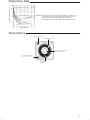
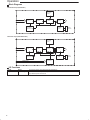
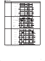
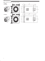
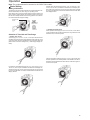
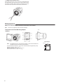
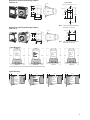
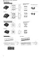
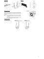
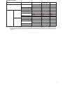
Solid-state Power OFF-delay Timer
H3CR-H
DIN 48 x 48-mm Solid-state Power
OFF-delay Timer
Long power OFF-delay times;
S-series: up to 12 seconds,
M-series: up to 12 minutes.
Models with forced-reset input are available.
11-pin and 8-pin models are available.
RC
Ordering Information
Input
Output
Supply voltage
S-series
11-pin models
---
DPDT
100 to 120 VAC
8-pin models
M-series
11-pin models
8-pin models
---
H3CR-H8L
---
H3CR-H8L
H3CR-HRL
---
H3CR-HRL
---
---
H3CR-H8RL
---
H3CR-H8RL
200 to 240 VAC
24 VAC/DC
48 VDC
100 to 125 VDC
With reset input
100 to 120 VAC
200 to 240 VAC
24 VAC/DC
48 VDC
100 to 125 VDC
SPDT
100 to 120 VAC
200 to 240 VAC
24 VAC/DC
48 VDC
100 to 125 VDC
Note:
Specify both the supply voltage and time unit code (S or M) in addition to the model number when ordering.
Example: H3CR-H8L 24 VAC/DC M
Time unit code
Supply voltage
Model Number Legend:
H3CR 1
2 3
4
1. Classification
H:
Power OFF-delay timer
2. Configuration
None: 11-pin socket
8:
8-pin socket
1
3. Input
None: Without reset input
R:
With reset input
4. Dimensions
L:
Long-body model
Accessories (Order Separately)
Name/specifications
Models
Flush Mounting
g Adapter
p
Y92F-30
Y92F-70
Y92F-71
Mounting Track
50 cm (l) x 7.3 mm (t)
PFP-50N
1 m (l) x 7.3 mm (t)
PFP-100N
1 m (l) x 16 mm (t)
PFP-100N2
End Plate
PFP-M
Spacer
PFP-S
Protective Cover
Y92A-48B
Track Mounting/
g
F
Front
t Connecting
C
ti Socket
S k t
8-pin
P2CF-08
11-pin
P2CF-11
Back Connecting
g Socket
8-pin
P3G-08
11-pin
P3GA-11
For PL08 and PL11 Sockets
Y92H-1
For PF085A Socket
Y92H-2
Hold-down Clip
Specifications
General
Item
H3CR-H8L
H3CR-H8RL
Operating/Reset method
Instantaneous
operation/Time-limit reset
Pin type
8-pin
Input type
---
No-voltage
Output type
Relay output (DPDT)
Relay output (SPDT)
Mounting method
DIN track mounting, surface mounting, and flush mounting
EMC
Emission Enclosure:
Emission AC Mains:
Immunity ESD:
Approved standards
UL508, CSA C22.2 No.14, LR/NK
Conforms to VDE0435/2021, VDE0110
Conforms to EN50081-2, prEN50082-2
H3CR-HRL
Instantaneous operation/Time-limit reset/Forced reset
11-pin
Relay output (DPDT)
EN55011 Group 1 class A
EN55011 Group 1 class A
IEC801-2: 4 kV contact discharge (level 2)
8 kV air discharge (level 3)
Immunity RF-interference:
ENV50140: 10 V/m (80 MHz to 1 GHz) (level 3)
Immunity Conducted Disturbance: ENV50141: 10 V (0.15 to 80 MHz) (level 3)
Immunity Burst:
IEC801-4: 2 kV power-line (level 3)
2 kV I/O signal-line (level 4)
Time Ranges
Time unit
Setting
Min. power ON time
Note:
0.6
0.05 to 0.6
1.2
0.1 to 1.2
6
0.5 to 6
12
1 to 12
0.1 sec min.
S-series
M-series
s (sec)
min
2 sec min.
If the above minimum power ON time is not secured, the H3CR may not operate. Be sure to secure the above minimum power ON time.
2
Ratings
Rated supply voltage (see note)
100 to 120 VAC (50/60 Hz), 200 to 240 VAC (50/60 Hz), 24 VAC/VDC (50/60 Hz), 48 VDC,
100 to 125 VDC
Operating voltage range
85% to 110% of rated supply voltage
No-voltage input
ON-impedance:
1 kΩ max.
ON residual voltage: 1 V max.
OFF impedance:
500 kΩ min.
Power consumption
100 to 120 VAC:
200 to 240 VAC:
24 VAC/DC:
48 VDC:
100 to 125 VDC:
Control outputs
Contact output: 5 A at 250 VAC, resistive load (cosφ = 1)
Note:
0.18 VA (100 VAC applied)
0.25 VA (200 VAC applied)
0.24 VA (24 VAC applied)/140 mW (24 VDC applied)
130 mW (48 VDC applied)
330 mW (125 VDC applied)
A power supply with a ripple of 20% max. (single-phase power supply with full-wave rectification) can be used with each DC Model.
Characteristics
3
Accuracy of operating time
±0.3% FS max. (±0.3% FS ±10 ms in ranges of 0.6 and 1.2 s)
Setting error
±5% FS ±0.05 s max.
Influence of voltage
±0.5% FS max. (±0.5% FS ±10 ms in ranges of 0.6 and 1.2 s)
Influence of temperature
±2% FS max. (±2% FS ±10 ms in ranges of 0.6 and 1.2 s)
Insulation resistance
100 MW min. (at 500 VDC)
Dielectric strength
2,000 VAC, 50/60 Hz for 1 min (between current-carrying metal parts and exposed
non-current-carrying metal parts)
2,000 VAC, 50/60 Hz for 1 min (between control output terminals and operating circuit)
1,000 VAC, 50/60 Hz for 1 min (between contacts not located next to each other)
Impulse withstand voltage
3 kV (between power terminals) for 100 to 120 VAC, 200 to 240 VAC, 100 to 125 VDC;
1 kV for 24 VAC/DC, 48 VDC
4.5 kV (between current-carrying terminal and exposed non-current-carrying metal parts) for
100 to 120 VAC, 200 to 240 VAC, 100 to 125 VDC;
1.5 kV for 24 VAC/DC, 48 VDC
Noise immunity
±1.5 kV (between power terminals) and ±600 V (between input terminals), square-wave noise
by noise simulator (pulse width: 100 ns/1 ms, 1-ns rise);
±1 kV (between power terminals) for 48 VDC
Static immunity
Malfunction: 8 kV
Destruction: 15 kV
Vibration resistance
Destruction:10 to 55 Hz with 0.75-mm single amplitude each in three directions
Malfunction:10 to 55 Hz with 0.5-mm single amplitude each in three directions
Shock resistance
Destruction: 980 m/s2 (100G) each in three directions
Malfunction: 98 m/s2 (10G) each in three directions
Ambient temperature
Operating:–10%C to 55%C (with no icing)
Storage: –25%C to 65%C (with no icing)
Ambient humidity
Operating: 35% to 85%
Life expectancy
Mechanical:10 million operations min. (under no load at 1,200 operations/h)
Electrical: 100,000 operations min. (5 A at 250 VAC, resistive load at 1,200 operations/h)
Case color
Light Gray (Munsell 5Y7/1)
Enclosure ratings
IEC: IP40
Weight
Approx. 120 g
Engineering Data
Switching operations (x 10 3 )
10,000
5,000
1,000
30 VDC L/R = 7 ms
500
250 VAC/30 VDC
(cosf = 1)
Reference: A maximum current of 0.15 A can be switched at 125 VDC (cosf = 1)
and a maximum current of 0.1 A can be switched if L/R is 7 ms. In
both cases, a life of 100,000 operations can be expected.
The minimum applicable load is 10 mA at 5 VDC (failure level: P).
100
250 VAC (cosf = 0.4)
Load current (A)
Nomenclature
Output indicator (red)
Scale range display windows
Time setting knob (for setting
power OFF-delay time)
Time range selector (select
one from 0.6, 1.2, 6, 12)
Time unit display
S-series: sec
M-series: min
4
Operation
Block Diagrams
Without Reset Input (H3CR-H8L)
Time range
selector
Oscillation
circuit
Counting
circuit
Power failure
detection circuit
Output
circuit
Indicator
circuit
LCD
Power supply
circuit
AC (DC) input
Output
indicator
With Reset Input (H3CR-H8RL/-HRL)
Time range
selector
Power supply
circuit
Oscillation
circuit
Counting
circuit
Indicator
circuit
Power failure
detection circuit
Reset input
Output
circuit
LCD
AC (DC) input
Output
indicator
Input circuit
I/O Functions
5
Inputs
Reset
Turns off the control output and resets the elapsed time.
Outputs
Control output
Operates instantaneously when the power is turned on and time-limit resets when the set time
is up after the power is turned off.
Timing Chart
Model
Timing chart
H3CR-H8L
Rt
Rt
t
ON
Power
t
OFF
Output (1 – 3)
Output (1 – 4)
Output (8 – 6)
Output (8 – 5)
Output
indicator
Lit
Not lit
H3CR-H8RL
ON
Power
Rt
Rt
t
t
OFF
0.05 s min.
0.05 s min.
ON (Short-circuited)
Reset input
OFF (Open)
Output (8 – 6)
Output (8 – 5)
Output
indicator
Lit
Not lit
H3CR-HRL
Rt
Power
ON
Rt
t
t
OFF
0.05 s min.
0.05 s
min.
Reset input
Output (1 – 3)
Output (1 – 4)
Output (11 – 9)
Output (11 – 8)
Output
indicator
Note:
Lit
Not lit
t: Set time
Rt: Minimum power ON time (S-series: 0.1 s min.; M-series: 2 s min.)
6
Dimensions
Note:
All units are in millimeters unless otherwise indicated.
H3CR-H8L
H3CR-H8RL
78.0
15
48
6
44.8 x 44.8
78.0
15
48
48
7
0.7
39 dia
48
H3CR-HRL
63.7
6
39 dia
63.7
0.7
44.8 x 44.8
Installation
Terminal Arrangement
8-pin Models
Without Reset Input (H3CR-H8L)
With Reset Input (H3CR-H8RL)
Reset
input
(–)
(~)
(–)
(~)
(+)
(~)
(+)
(~)
Power supply
Power supply
Note:
Leave terminal 3 open. Do not use
them as relay terminals.
Note:
Leave terminal 6 open. Do not use
them as relay terminals.
11-pin Model
With Reset Input (H3CR-HRL)
Reset input
(–)(~)
(+)(~)
Power supply
8
Operation
Note: The undermentioned is common for all H3CR-F/G/H models.
Basic Setting
Setting of Selectors
The selectors can be turned clockwise and counterclockwise to select the desired time unit, time range, or operating mode.
Each selector has a snap mechanism that secures the selector at a
given position. Set the selector at a position at which it is secured.
Do not set it midway between two securing positions or a malfunction could result from improper setting.
For OFF-time, the desired time unit (sec, 10 s, min, and hrs, or 10 s,
10 min, hrs, and 10 h) is indicated in the OFF-time unit display window at the upper right corner of the front panel and can be changed
by turning the OFF-time unit selector located below the OFF-time
unit display window.
Operating mode
selector
Operating mode
display window
Groove for
screwdriver
(i.e., H3CR-A)
Selection of Time Unit and Time Range
• H3CR-F Twin Timers
•
H3CR-G Star-delta Timers
A star operation time range (0 to 6, 0 to 12, 0 to 60, or 0 to 120 seconds) is selected with the star operation time range selector at the
lower left corner of the front panel.
A time range (0 to 1.2, 0 to 3, 0 to 12, or 0 to 30) is selected for ONand OFF-time using the time range selector at the lower left corner
of the front panel, and the selected time range appears within the
plastic frame of the time setting knob (= scale range display windows).
The time required for switching (0.05, 0.1, 0.25, or 0.5 second) from
the star operation to the delta operation of the H3CR-G can be selected with the star-delta transfer time selector at the lower right corner of the front panel.
For ON-time, the desired time unit (sec, 10 s, min, and hrs, or 10 s,
10 min, hrs, and 10 h) is indicated in the ON-time unit display window at the lower right corner of the front panel and can be changed
by turning the ON-time unit selector located below the ON-time unit
display window.
9
•
H3CR-H Power OFF-delay Timers
A time range (0 to 0.6, 0 to 1.2, 0 to 6, and 0 to 12) is selected with the
time range selector at the lower left corner of the front panel. No time
unit selector is available. When ordering the H3CR-H, specify S (for
the second unit) or M (for the minute unit) for your H3CR-H.
Dimensions
Note: The undermentioned is common for all H3CR-F/G/H models.
Note:
All units are in millimeters unless otherwise indicated.
Dimensions with Flush Mounting Adaptor
Y92F-30
Panel
58
52
42
48
Panel Cutout
Note:
The adapters for two or more timers mounted in a vertical line are different in
orientation from those mounted in a horizontal line.
N can be obtained as follows (n: the number of H3CR models arranged side by side)
Without a Cover: N = (48n - 2.5) +1/-0
With the Protective Cover: N = (51n - 5.5) +1/-0
With the Panel Cover: N = (50n - 4.5) +1/-0
10
0.5 R max.
+0.6
45 –0
+0.6
45 –0
(N)
Dimensions with Flush Mounting Adaptor
Y92F-73/-70
Panel Cutout
Panel
Adapter mounting hole Two, 4.5 dia.
R0.5 max.
45±
88 0.15
52 to 53
65 to 66
76±0.2
45±0.15
58
Note:
Dimensions with Flush Mounting Adaptor
Y92F-74/-71
Panel
56
58
The mounting panel thickness
should be 1 to 3.2 mm.
R0.5 max.
+0.5
68
45±0.2
+0.5
45 –0
55 –0
43±0.2
Note:
+0.2
50 –0
The mounting panel thickness
should be 1 to 3.2 mm.
Track Mounting
102.8
11-pin,
short body
models:
eg. H3CR-F
100.5
P2CF-11
2.3*
91.9
8-pin
Short body
models:
eg.
H3CR-F8
P2CF-08
89.6
111.7*
11-pin, long
body
models:
eg.
H3CR-HRL
P2CF-11
2.3*
109.4
100.7*
8-pin, long
body
models:
eg.
H3CR-H8L
P2CF-08
2.3*
98.4
2.3*
*These dimensions vary with the kind of DIN track (reference value).
Flush Mounting
17
17
80
P3GA-11
Y92F-30
15
91.4
85.4
8-pin, long
body
models:
eg.
H3CR-H8L
11-pin, long
body
models:
eg.
H3CR-HRL
8-pin
short-body
models:
eg. H3CR-F
11-pin,
short body
models:
eg. H3CR-F
Y92F-30
15
75
P3G-08
Y92F-30
P3GA-11
Y92F-30
P3G-08
11
3
Accessories (Order Separately)
Track Mounting/
Front Connecting Socket
P2CF-08
Eight,
M3.5 x 7.5 sems
3
7.8
Terminal Arrangement/
Internal Connections
(Top View)
4.5
Surface Mounting Holes
Two, 4.5 dia. or two, M4
70 max.
35.4
Two, 4.5 dia.
holes
40±0.2
4
50 max.
20.3 max.
P2CF-11
Eleven,
M3.5 x 7.5 sems
3
4.5
Two, 4.5 dia. mounting holes
7.8
40±0.2
70 max.
35.4
Two, 4.5 dia.
holes
4
50 max.
31.2 max.
Back Connecting Socket
P3G-08
Terminal Arrangement/
Internal Connections
(Bottom View)
27 dia.
45
45
P3GA-11
4.9
17
27 dia.
45
25.6
4.5
45
6.2
16.3
Mounting Track
PFP-100N, PFP-50N
PFP-100N2
16
7.3±0.15
4.5
4.5
35±0.3
15
25
25
10
25
25
10
L
L: Length
1m
50 cm
1m
12
PFP-100N
PFP-50N
PFP-100N2
*
27±0.15
1
35±0.3
15
25
25
10
25
L
25 15
10
27
24
29.2
1
1.5
End Plate
PFP-M
Spacer
PFP-S
10
6.2
16
12
5
1.8
1
35.5 35.3
50
11.5
34.8
44.3
1.8
1.3
10 M4 x 8
pan head
screw
4.8
16.5
Y92A-48B
Protective Cover
Y92A-48B
The protective cover protects the front panel, particularly the time
setting section, against dust, dirt, and water. It also prevents the set
value from being altered due to accidental contact with the time setting knob.
Note: 1. The Y92A-48B Protective Cover is made of a hard plastic and therefore it must be removed to change the timer
set value.
2. The Protective Cover cannot be mounted if the Panel
Cover (sold separately) is used on the Timer.
Hold-down Clip
Y92H-7/-1
For PL08 and PL11 Sockets
Y92H-8/-2
For PF085A Socket
13
Precautions
Note: The undermentioned is common for all H3CR-F/G/H models.
Power Supplies (H3CR-H)
NOTICE:
Do not change the time unit, time range, or operation
mode while the timer is in operation or malfunction could
result.
Wiring (H3CR-H)
The H3CR has a high impedance circuit. Therefore, the H3CR may
not be reset if the H3CR is influenced by inductive voltage. In order
to eliminate any influence of inductive voltage, the wires connected
to the H3CR must be as short as possible and should not be
installed alongside power lines. If the H3CR is influenced by inductive voltage that is 30% or more of the rated voltage, connect a CR
filter with a capacitance of approximately 0.1 µF and a resistance of
approximately 120 Ω or a bleeder resistor between the power supply terminals. If there is any residual voltage due to current leakage,
connect a bleeder resistor between the power supply terminals.
An AC power supply can be connected to the power input terminals
without regarding polarity. A DC power supply must be connected to
the power input terminals as designated according to the polarity of
the terminals.
A DC power supply can be connected if its ripple factor is 20% or
less and the mean voltage is within the rated operating voltage
range of the Timer.
Connect the power supply voltage through a relay or switch in such
a way that the voltage reaches a fixed value at once or the Timer
may not be reset or a timer error could result.
For the power supply of an input device, use an isolating transformer, of which the primary and secondary windings are mutually isolated and the secondary winding is not grounded.
H3CR
Operation (H3CR-H)
Input
terminal
An interval of 3 s minimum is required to turn on the H3CR after the
H3CR is turned off. If the H3CR is turned on and off repeatedly with
an interval of shorter than 3 s, the internal parts of the H3CR may
deteriorate and the H3CR may malfunction.
3 s min.
Circuit
Power
Output
state 1
Output
state 2
After the forced reset function of the H3CR is activated, an interval
of 3 s minimum is required to activate the forced reset function
again. If the forced reset function is activated repeatedly with an interval of shorter than 3 s, the internal parts of the H3CR may deteriorate and the H3CR may malfunction.
Power
3 s min.
3 s min.
Reset
input
Output
If it is required that the output be turned on repeatedly with an interval of shorter than 3 s, consider use of the H3CR-A in mode D (signal OFF-delay).
14
Rectifier circuit
Changing of Setting
Power supply
Isolation transformer is required.
The H3CR-H has a large inrush current; provide sufficient power
supply capacity. If the power supply capacity is too small, there may
be delays in turning ON the output.
The power supply circuit of any H3CR-Fj 100-to-240-VAC model,
and H3CR-Gj 100/110/120-VAC and 200/220/240-VAC model is a
switching circuit. If the power line connected to the power supply circuit has a transformer with high inductance, a counter-electromotive voltage will be induced by the inductance. To suppress the voltage, apply a CR filter to the power supply line.
Inrush Current
Model
H3CR-F
H3CR-H
24 VAC/DC
S-series
M-series
Note:
Voltage
Applied voltage
Inrush current
(peak value)
Time
26.4 VAC
0.7 A
10 ms
26.4 VDC
1.1 A
9.4 ms
12 VDC
13.2 VDC
52 mA
3.3 ms
48 to 125 VDC
137.5 VDC
0.40 A
9.1 ms
100/110/120 VAC
132 VAC
1.05 A
111 ms
200/220/240 VAC
264 VAC
1.07 A
119 ms
24 VAC/DC
26.4 VAC
1.26 A
133 ms
26.4 VDC
0.85 A
137 ms
48 VDC
52.8 VDC
0.73 A
112 ms
100 to 125 VDC
137.5 VDC
0.62 A
109 ms
100/110/120 VAC
132 VAC
1.02 A
364 ms
200/220/240 VAC
264 VAC
1.03 A
323 ms
24 VAC/DC
26.4 VAC
1.21 A
478 ms
26.4 VDC
0.87 A
560 ms
48 VDC
52.8 VDC
0.71 A
384 ms
100 to 125 VDC
137.5 VDC
0.62 A
380 ms
1. The above figures are all approximations and should be used for reference only.
2. The inrush current is given mainly for DC models for the required power supply design specifications. For the H3CR-H, the inrush
current is also given for 100/110/120-VAC and 200/220/240-VAC models because these models have higher inrush currents than
other series.
15
Input/Output (H3CR-H)
Others
An appropriate input is applied to the input signal terminal of the Timer when the input terminal for the input signal is short-circuited. Do
not attempt to connect any input terminal to any terminal other than
the input terminal or to apply voltage across other than the specified
input terminals or the internal circuits of the Timer may be damaged.
Input contact
Power supply
AC or DC
*
H3CR
Input
terminal
L
*Do not connect a relay or any other load between these two
points, otherwise the internal circuit of the Timer may be
damaged due to the high-tension voltage applied to the input
terminals.
When connecting a relay or a transistor as an external signal input
device, pay attention to the following points to prevent short-circuiting due to a sneak current to the transformerless power supply.
If a relay or transistor is connected to two or more Timers, the input
terminals of those Timers must be wired properly so that they will not
be different in phase or the terminals will be short-circuited to one
another (refer to the figures below).
Contact or transistor for
external input signal
H3CR series timer
Input
terminal
Power supply
Incorrect
Short-circuit
current
Input
terminal
Input
terminal
Power supply
Correct
Input
terminal
Environment
When using the Timer in an area with excess electronic noise, separate the Timer, wiring, and the equipment which generates the input
signals as far as possible from the noise sources. It is also recommended to shield the input signal wiring to prevent electronic interference.
Organic solvents (such as paint thinner), as well as very acidic or
basic solutions can damage the outer casing of the Timer.
16
If the Timer is mounted on a control board, dismount the timer from
the control board or short-circuit the circuitry of the power board before carrying out a voltage withstand test between the electric circuitry and non current-carrying metal part of the Timer, in order to
prevent the internal circuitry of the Timer from damage.
ALL DIMENSIONS SHOWN ARE IN MILLIMETERS.
To convert millimeters into inches, multiply by 0.03937. To convert grams into ounces, multiply by 0.03527.
Cat. No. L86-E1-2B
In the interest of product improvement, specifications are subject to change without notice.
OMRON Corporation
Systems Components Division
28th Fl., Crystal Tower Bldg.
1-2-27, Shiromi, Chuo-ku,
Osaka 540 Japan
Phone: 06-949-6012 Fax: 06-949-6021
Printed in Japan
0697-0.5M (0696) a
17


![H5DA(M)IA [轉換].ai - Anly Electronics Co., Ltd.](http://vs1.manualzilla.com/store/data/005881219_1-4b829119a0226e59b0b94ecac6325c4d-150x150.png)