1
GatorCam4 Radiodetection’s advanced digital video inspection system Operation Manual l Issue 1 l March 2011 90/GC4-OPMAN-ENG/01 Preface Before you begin Please read this operation manual before attempting to use the GatorCam4USB system. Note that this manual and all its contents are subject to change. Radiodetection products are under continuous development. Radiodetection reserves the right to modify any product, including this manual, without notice and some product changes may have taken place after this user manual was published. Contact your local Radiodetection dealer or visit www.radiodetection.com for the latest information about the GatorCam4USB product family, including all accessories, documentation and software updates. Important safety notices Please observe all safety notices and warnings in this manual before operating any Radiodetection product. Warnings, Cautions and Notes WARNING!: Warnings alert you to possible personal injury. CAUTION: Cautions alert you to possible equipment damage. NOTE: Notes contain useful information. Key to symbols used General Warning: Refer to Manual for specific instruction or advice. Electrical Hazard: Observe safe practices and exercise extreme caution. Heavy object: Additional care must be taken when lifting. Biohazard: Disinfect after use. Wear appropriate personal protective equipment (PPE). Hot Surface: Allow to cool or use appropriate protection when handling. General Radiodetection has taken care to provide the necessary information in this manual for the safe installation, operation, maintenance and disposal of this equipment. However, a risk assessment should be performed prior to commencing work as it may highlight additional safety issues specific to the application. GatorCam4 Operation Manual ii Installation The GatorCam4USB , including its component parts is heavy. If available, use the wheels to assist transport. Observe heavylifting safety practices when lifting any component of this system. Refer to the specifications in Appendix 12.5 for a description of the system‟s dimensions and weights. If mains operated equipment is connected to the system then the external equipment must be earthed in accordance with the manufacturer‟s instructions. Failure to comply with this may cause the unit to become live and a LETHAL HAZARD. Operation guidelines Please observe your company, region or country‟s Standard Code of Practice for surveying underground utilities with CCTV equipment, if applicable, when using this equipment. Always carry out a risk assessment of the site to be inspected. This equipment is NOT approved for use in areas where hazardous gasses may be present. Foul water systems can be a source of serious biological hazards. Wear appropriate protection (PPE) when handling the GatorCam4USB . The camera will get hot during use. This is normal. Exercise care when handling the camera at all times. System components must NOT be connected/disconnected when the power is on. Take care to ensure that video and power cables do not get entangled in the reel. Cables ties are recommended and will not impede system performance. Always store the GatorCam4USB system in a clean and dry environment. Safety precautions Ensure that standard safety precautions for working in hostile environments are followed. The GatorCam4USB system requires connection to a protective earth; if in doubt, consult a qualified electrician. Electrical equipment is factory tested for electrical safety. Routine inspection is recommended (and may be required by law) to maintain this level of protection. If you are unsure, contact your local safety authority for advice. Always use heavy-duty industrial gloves when handling rod which is being withdrawn from a sewer. Always ensure that cabling is properly connected. Always switch the system on and off using the controller switch. The rod can retain a large amount of energy when coiled and can cause injury if not correctly handled. The risk of injury from the rotating reel increases with speed of rotation. Adjust the brake position to allow smooth deployment of the rod. To avoid risk of burns, do not touch the camera when it is switched on or immediately after switch off. Leave ample time for it to cool before handling. The camera‟s LEDs are very powerful. Do not look directly at the LEDs or point them at other people. GatorCam4 Operation Manual iii Maintenance Clean and sanitize the GatorCam4USB system at regular intervals and after conducting an inspection. Always keep all connectors covered with their protective caps when the equipment is not in use. Do not dismantle any component of this system unless directed by this operation manual. Dismantling components not specified by this manual may void the product warranty. Radiodetection recommends that only authorized service centers carry out service of this product. Service elsewhere will void the warranty. For information regarding any service needs, please visit www.radiodetection.com or contact your local Radiodetection representative or dealer. Disposal Do not dispose of this product in municipal waste facilities. Please check local regulations for disposal of electronic products. Radiodetection complies with the requirements of 2002/96/EC Waste Electrical and Electronic Equipment. Compliance EU Compliance This equipment complies with the following EU Directives: Low Voltage Directive: 2006/95/EC Machinery Directive: 2006/42/EC EMC Directive: 2004/108/EC FCC Compliance Statement This equipment complies with Part 15 of the FCC Rules. Operation is subject to the following two conditions: The equipment may not cause harmful interference. The equipment must accept any interference received, including interference that may cause undesired operation. NOTE: This equipment has been tested and found to comply with the limits for a Class A digital device pursuant to Part 15 of the FCC Rules. These limits are designed to provide reasonable protection against harmful interference when the equipment is operated in a commercial environment. This equipment generates, uses, and can radiate radio frequency energy and, if not installed and used in accordance with the manufacturer‟s instruction manual, may cause harmful interference with radio communications. Operation of this equipment in a residential area is likely to cause harmful interference, in which case you will be required to correct the interference at your own expense. GatorCam4 Operation Manual iv Modifications: Any modifications made to this equipment that are not approved by Radiodetection may void the authority granted to the user by the FCC to operate this equipment. Industry Canada Compliance Statements ICES-003 Class A Notice: This Class A digital apparatus complies with Canadian ICES-003. Avis NMB-003, Classe A: Cet appareil numérique de la classe A est conforme à la norme NMB-003 du Canada Trademarks Flexisight Manager and RD7000DL+ are trademarks of Radiodetection Ltd, all rights reserved. SPX, Radiodetection are trademarks of SPX Corporation and Radiodetection Ltd. Microsoft Word, Microsoft Office 97, Windows XP, Windows Vista and Windows 7 are either registered trademarks or trademarks of Microsoft Corporation in the United States and/or other countries. QuickTime, Mac, Mac OS, Finder, iMovie and Final Cut Pro are trademarks of Apple Inc., registered in the U.S and other countries. Other trademarks or registered trademarks mentioned in this document belong to their respective owners. Disclaimer Any third-party products (including hardware, software and services) mentioned in this manual are for instructional purposes only and are not an endorsement by Radiodetection Ltd or SPX Corporation. Radiodetection Ltd does not accept any liability for loss of data or damage to equipment when using any third-party products. Copyright statement Copyright 2011 Radiodetection Ltd– SPX Corporation. All rights reserved. Radiodetection is a subsidiary of SPX Corporation. SPX, Radiodetection and are trademarks of SPX Corporation and Radiodetection Ltd. Due to a policy of continued development, we reserve the right to alter or amend any published specification without notice. This document may not be copied, reproduced, transmitted, modified or used, in whole or in part, without the prior written consent of Radiodetection Ltd. Training Radiodetection provides training services for most Radiodetection products. Our qualified instructors will train equipment operators or other personnel at your preferred location or at Radiodetection headquarters. For more information go to www.radiodetection.com or contact your local Radiodetection representative. GatorCam4 Operation Manual v GatorCam4 Operation Manual vi Contents Section 1 - Introduction......................................................................... 1 1.1 About this manual ..............................................................................................................................................................1 1.2 Overview ............................................................................................................................................................................1 1.2.1 GatorCam4USB features ...............................................................................................................................................2 1.3 Safety notices .....................................................................................................................................................................2 1.4 Latest updates and information ..........................................................................................................................................2 Section 2 - System Overview ................................................................ 3 2.1 2.1.1 2.2 Controller ...........................................................................................................................................................................3 Keypad ...........................................................................................................................................................................5 Pushrod reels and cameras ..................................................................................................................................................6 2.2.1 Pushrod reels and cameras .............................................................................................................................................6 2.2.2 Accessories (not shown): ...............................................................................................................................................7 Section 3 - Quick start guide ................................................................. 8 3.1 Quick start procedure .........................................................................................................................................................8 Section 4 - System Assembly .............................................................. 10 4.1 Controller .........................................................................................................................................................................10 4.1.1 Mounting ......................................................................................................................................................................10 4.1.2 Power ...........................................................................................................................................................................10 4.1.3 Compact Flash card ......................................................................................................................................................10 4.1.4 USB flash drive ............................................................................................................................................................10 4.1.5 Keyboard ......................................................................................................................................................................11 4.1.6 Headset .........................................................................................................................................................................11 4.2 Pushrod reel ......................................................................................................................................................................11 4.3 Camera and accessories ....................................................................................................................................................11 4.3.1 Camera .........................................................................................................................................................................11 4.3.2 Focusing the cameras ...................................................................................................................................................12 4.3.3 Flexisondes and solid sonde .........................................................................................................................................12 4.3.4 Universal flexi ..............................................................................................................................................................12 GatorCam4 Operation Manual vii 4.3.5 Skids and brushes .........................................................................................................................................................12 4.3.6 W-Skids........................................................................................................................................................................14 4.4 Battery pack ......................................................................................................................................................................14 4.5 External Video Equipment ...............................................................................................................................................15 Section 5 - Controller and system set-up............................................. 16 5.1 Overview ..........................................................................................................................................................................16 5.2 Powering up ......................................................................................................................................................................16 5.3 Getting help ......................................................................................................................................................................16 5.4 Welcome screen ...............................................................................................................................................................17 5.5 On-Screen Information .....................................................................................................................................................18 5.6 System Menu ....................................................................................................................................................................19 5.6.1 General Navigation and text entry ...............................................................................................................................19 5.7 Setup menu .......................................................................................................................................................................20 5.8 Setting up your controller .................................................................................................................................................21 5.8.1 Basic Settings ...............................................................................................................................................................21 5.8.2 Recording: ....................................................................................................................................................................22 5.8.3 File Names: ..................................................................................................................................................................22 5.8.4 Video Titles ..................................................................................................................................................................23 5.8.5 Video Quality ...............................................................................................................................................................24 5.9 Setting up your Reel .........................................................................................................................................................25 5.10 Setting up your On-Screen Information ...........................................................................................................................26 5.10.1 5.11 Choosing an On-Screen Information layout ............................................................................................................26 Company details ...............................................................................................................................................................28 Maintenance ...................................................................................................................................................................................29 5.11.1 How to update your controller software ..................................................................................................................29 5.11.2 How to modify your Job Templates.........................................................................................................................30 Section 6 - System operation............................................................... 31 6.1 Before you begin ..............................................................................................................................................................31 6.2 Calibration ........................................................................................................................................................................31 6.3 Deploying the camera .......................................................................................................................................................32 GatorCam4 Operation Manual viii 6.3.1 Zero the Rod Counter ...................................................................................................................................................32 6.4 Video recording ................................................................................................................................................................32 6.5 Still pictures......................................................................................................................................................................33 6.6 Digital image controls ......................................................................................................................................................33 6.6.1 Pan ...............................................................................................................................................................................33 6.6.2 Rotate ...........................................................................................................................................................................34 6.6.3 Zoom ............................................................................................................................................................................34 6.7 Retrieving the camera .......................................................................................................................................................34 Section 7 - Memory Storage and File management ............................ 35 7.1 Supported storage devices ................................................................................................................................................35 7.2 File browser ......................................................................................................................................................................36 7.2.1 File types ......................................................................................................................................................................37 7.2.2 Copying files ................................................................................................................................................................37 7.2.3 Moving .........................................................................................................................................................................37 7.2.4 Deleting files and folders .............................................................................................................................................38 7.2.5 Creating folders ............................................................................................................................................................38 7.2.6 Information ..................................................................................................................................................................38 7.3 Viewing JPEG pictures.....................................................................................................................................................39 7.4 Playing videos ..................................................................................................................................................................40 7.4.1 7.5 7.5.1 Screen captures ............................................................................................................................................................40 PC USB connections ........................................................................................................................................................40 Disconnecting...............................................................................................................................................................41 Section 8 - Text pages ......................................................................... 42 8.1 Video Text Pages..............................................................................................................................................................42 8.2 Text Menu ........................................................................................................................................................................42 8.2.1 Overlaying a text page .................................................................................................................................................43 8.2.2 Creating or editing text pages ......................................................................................................................................43 8.2.3 Importing or exporting a text page ...............................................................................................................................44 Section 9 - Jobs, observations and reporting ....................................... 45 9.1 JOBS ................................................................................................................................................................................46 GatorCam4 Operation Manual ix 9.2 One-click recording and Quick Job start ..........................................................................................................................47 9.3 Job Browser ......................................................................................................................................................................48 9.4 Job Reviewer ....................................................................................................................................................................48 9.4.1 9.5 Active Jobs ...................................................................................................................................................................49 Job details (Creating a new Job) .......................................................................................................................................50 9.5.1 Personalizing your Job templates .................................................................................................................................50 9.5.2 Default Client form ......................................................................................................................................................50 9.5.3 Default Site form ..........................................................................................................................................................51 9.5.4 Default Survey form.....................................................................................................................................................51 9.6 Inspection Details .............................................................................................................................................................52 9.7 Observations .....................................................................................................................................................................53 9.7.1 Default Observation form ............................................................................................................................................53 9.7.2 Adding a photo to an observation. ...............................................................................................................................54 9.7.3 Observation popup .......................................................................................................................................................54 9.8 Comments (Freetext) ........................................................................................................................................................55 9.9 Defect code list .................................................................................................................................................................55 9.10 HTML Report ...................................................................................................................................................................55 9.10.1 Folder structure ........................................................................................................................................................55 9.10.2 Browsing and printing .............................................................................................................................................56 Section 10 - Flexisight Manager ......................................................... 57 10.1 Installing Flexisight Manager ...........................................................................................................................................57 10.2 Running Flexisight Manager for the first time .................................................................................................................59 10.3 Flexisight Manager ...........................................................................................................................................................59 10.4 Job Browser ......................................................................................................................................................................60 10.4.1 Importing your inspections ......................................................................................................................................60 10.4.2 Reviewing your Jobs...............................................................................................................................................61 10.4.3 Filtering your Jobs ...................................................................................................................................................62 10.5 Survey Window ................................................................................................................................................................63 10.5.1 Reviewing your surveys ..........................................................................................................................................64 10.5.2 Review or modify survey information .....................................................................................................................65 GatorCam4 Operation Manual x 10.5.3 Survey‟s videos and pictures ...................................................................................................................................66 10.5.4 Reviewing a video ..................................................................................................................................................66 10.5.5 Reviewing Observations ..........................................................................................................................................68 10.5.6 Creating Reports ......................................................................................................................................................69 10.6 Editing (Annotating) a picture ..........................................................................................................................................69 10.6.1 Adding an arrow to your picture ..............................................................................................................................70 10.6.2 Adding a circle to your picture ................................................................................................................................70 10.6.3 Graphic Color .........................................................................................................................................................71 10.6.4 Adding text to your picture .....................................................................................................................................71 10.6.5 Changing text color..................................................................................................................................................71 10.6.6 Changing text font ...................................................................................................................................................71 10.7 Video Editor .....................................................................................................................................................................72 10.7.1 Reviewing a video file in the video editor ...............................................................................................................72 10.7.2 Cutting a video file ..................................................................................................................................................73 10.7.3 Editing video cuts ....................................................................................................................................................74 10.7.4 Creating a new video file .........................................................................................................................................75 10.7.5 Concatenating multiple files ....................................................................................................................................76 10.8 Utility Menu .....................................................................................................................................................................76 10.8.1 Base folder ...............................................................................................................................................................77 10.8.2 Edit Company Information. .....................................................................................................................................78 10.8.3 Creating a text page with Flexisight Manager. ........................................................................................................78 10.8.4 Report Layout Options ............................................................................................................................................78 10.8.5 Defect Codes editor .................................................................................................................................................79 10.8.6 Export Defect Codes and Modified Templates for use by the controller .................................................................81 10.9 Customizing the Word template .......................................................................................................................................83 10.10 Removing Flexisight Manager .........................................................................................................................................84 Section 11 - Digital Video................................................................... 85 11.1 Video Specification ..........................................................................................................................................................85 11.2 Video Quality settings ......................................................................................................................................................85 11.3 Video playback .................................................................................................................................................................85 GatorCam4 Operation Manual xi 11.3.1 Controller playback .................................................................................................................................................85 11.3.2 Computer playback ..................................................................................................................................................85 11.4 Distributing your recordings .............................................................................................................................................87 11.4.1 Producing a DVD video ...........................................................................................................................................88 11.4.2 Supported digital video files ....................................................................................................................................89 11.4.3 Unsupported digital video files ...............................................................................................................................89 11.4.4 Using data CDs, DVDs and flash memory devices .................................................................................................90 11.5 Converting digital videos ................................................................................................................................................91 11.5.1 System Requirements ..............................................................................................................................................91 11.5.2 Conversion software for Windows ..........................................................................................................................92 11.5.3 Conversion software for Mac OS X ........................................................................................................................93 11.6 Advanced video editing ....................................................................................................................................................93 11.6.1 Flexisight Manager ..................................................................................................................................................93 11.6.2 DV ...........................................................................................................................................................................93 Section 12 - Appendix......................................................................... 95 12.1 Shortcuts ...........................................................................................................................................................................95 12.2 Clamp assembly ...............................................................................................................................................................96 12.3 Care and maintenance......................................................................................................................................................96 12.3.1 Terminals and O-rings .............................................................................................................................................96 12.3.2 Cleaning the system .................................................................................................................................................97 12.3.3 Storing the system....................................................................................................................................................97 12.4 AVC Video license ...........................................................................................................................................................97 12.5 Specifications ...................................................................................................................................................................98 GatorCam4 Operation Manual xii Section 1 - Introduction 1.1 About this manual This manual provides comprehensive operating instructions for the GatorCam4USB ™ pipeline video inspection system. Before attempting to operate the GatorCam4USB system, it is very important that you read this manual, noting all safety warnings and procedures in the Preface, Section 1.3 and throughout the rest of the manual. Once you have read this manual, it is recommended that you retain it for reference purposes. A printed version of this manual is available on request. Please contact your local Radiodetection representative for more information. The rest of the manual is detailed as follows:Section 2 includes annotated illustrations of the controller, pushrod reels and selected accessories. Section 3 provides users with quick start instructions to operating the controller. Section 4 provides a detailed guide to assembling the system ready for conducting inspections. Section 5 provides a comprehensive introduction to using and configuring the controller. Section 6 introduces the basics of pipeline inspections and describes how to deploy the rod, create video recordings and control the camera during an inspection. Section 7 introduces the Compact Flash card / USB flash drive browser and provides a detailed guide to managing survey files. Section 8 introduces the Text Page overlay functionality, explaining how to edit or import and display text pages. Section 9 introduces the way the Controller stores information, including Jobs, Observations and Reporting. Section 10 introduces Flexisight Manager PC Data management, storage editing and reporting tool that accompanies the system. Section 11 provides a comprehensive guide to digital video options and settings. Section 11 also includes a guide to converting and distributing videos for playback on computers and other video equipment. Section 12 is an appendix that includes reference and other important information as well as instructions on caring for and maintaining your GatorCam4USB system. 1.2 Overview The GatorCam4USB is an advanced pipeline video inspection system that is ideal for a broad range of applications. This system allows operators to identify and document pipeline faults using the latest in digital video recording technology. The GatorCam4USB is a fully modular system; the controller can drive any combination of the GatorCam4USB range of pushrod reels and cameras. GatorCam4 Operation Manual 1 1.2.1 GatorCam4USB features • One Touch recording using industry standard H.264 video and AAC audio format. • Record up to 50 minutes of high-quality video per gigabyte of memory. For more information about video recording settings and quality, please refer to Section 5.8.5. NOTE: Recording length for a given file size is not fixed and depends on a large number of factors including, among other things, the live picture that is being recorded. Constant movement in the camera‟s focus, for example, will produce larger file sizes per minute of recorded footage. The unit can record up to 4.5 hours per gigabyte using the low quality setting. • Pan, zoom and rotate live video or your recordings. • Still image capturing using industry-standard jpeg format. Integrated reporting. Reports are generated by the GatorCam4USB controller in HTML format compatible with Internet Explorer 6.0 or higher, and can be converted by Flexisight™ Manager into a Microsoft Word document, providing you have Microsoft Office 97 or higher installed. 1.3 Safety notices Caution must be taken when conducting any pipeline or drainage system inspection. Please observe all safety warnings detailed in the Preface and throughout this operation manual. Before you attempt to operate the GatorCam4USB system, it is recommended that you familiarize yourself with any additional health and safety requirements that may be defined by company policy and any applicable local or national laws. Contact your company‟s or local government‟s health and safety officer for further information. 1.4 Latest updates and information Radiodetection may have released new system software, user documentation or other information after you purchased your system. You can download the latest software, documentation and application notes from www.radiodetection.com. For more information about checking and upgrading your system‟s software, please refer to Section 5.11.1 GatorCam4 Operation Manual 2 Section 2 - System Overview The GatorCam4 pushrod inspection system comprises of a controller, pushrod reel, camera and accessories. This subsection provides a detailed, illustrated overview of these components. 2.1 Controller The GatorCam4USB unit acts as the controller and digital video recorder and playback device. Video is displayed on an 8" industrial LCD. Video, pictures and inspection reports are stored on a compatible high-speed Compact Flash card or USB flash drive. See Figures 2.1 to 2.3 1. On/Off Switch: Switches power ON or OFF. 2. Keypad and function keys: Allows the operator to control the system, select functions and edit text entries. 3. Keyboard: Provides enhanced text entry capabilities and shortcuts to access system functions. 4. Display: LCD Screen shows video, still images and various on-screen system information. 5. Link Cable Socket: To connect the pushrod reel to the controller with a link cable. 6. Controller support clamp: To mount the controller onto the reel (optional on the Mini model). 7. Fuse holder: 5mm x 20mm T3.15A 250V cartridge fuse. 8. RCA Video Jacks: Provide secondary input and output options for external composite video equipment. 9. Power Socket: DC power input from vehicle supply, battery box or mains adaptor. 10. Compact Flash card slot: The controller can use a Compact Flash card to store video recordings, reports and pictures. Most stored files can be viewed or played on the controller or transferred to PC. Also used to store and upload software upgrades. 11. Keyboard Socket: Connects the keyboard. 12. Audio Socket: Connects the optional headset to record/playback audio over videos. 13. USB Socket: The controller can use a USB flash drive to store video recordings, reports and pictures. Most stored files can be viewed or played on the controller or transferred to PC. Also used to store and upload software upgrades. 14. PC socket. USB (type B) connection to transfer files to computers. GatorCam4 Operation Manual 3 Figure 2.1: Controller Module Figure 2.2 Controller Rear View 7 12 8 13 14 9 11 10 Figure 2.3 Controller I/O Panel GatorCam4 Operation Manual 4 2.1.1 Keypad See Figure 2.4 15. Function keys: Use to select menu items or activate short cuts. 16. Camera key: Press to take screen captures. 17. Text key: Press to access the Text and Report menu. 18. Play: Enters the card browser menu. Starts or continues video playback of selected file. 19. Pause: Press to pause or restart video playback or recording. 20. Record: Press to begin a new video recording. 21. Stop: Press to stop video playback or recording. 22. Crawler stop key: Not functional on this model. 23. Arrow keys: Use for navigation and to select system parameters. 24. OK: Press to select or confirm choices in the menu system. 25. LED Brightness/Camera Focus keys: not functional on this model. 26. Rotate/Pan keys: Press to rotate the camera view. Fn + Rotate to pan left or right. Simultaneous press will re-center the view. 27. Zoom/Iris keys: Press to zoom in or out of the camera‟s subject. Fn + Zoom to modify the Iris. (Iris not functional on this model). Simultaneous press will reset the zoom to unity. 28. Function key (Fn): Press and hold in combination with other keys to activate alternate functions. Figure 2.4: Controller Keypad GatorCam4 Operation Manual 5 2.2 Pushrod reels and cameras 2.2.1 Pushrod reels and cameras See Figures 2.5 to 2.8. Figure 2.5: Specialist Pushrod Reel 1. Pushrod Reel: Holds the pushrod on a revolving reel. The pushrod can be up to 500ft (150m) in length. 4 5 1 2. Pushrod Guide: Guides the rod on and off the reel. 3. Brake: Can be adjusted to control the movement of the reel, or to lock it. 4. Adaptor Clamp (optional on the Plumbers and Mini models): Allows the controller to be mounted onto the pushrod reel. 5. Stowage Hooks: To store the link cable on the push- rod reel. 6. Link Cable Socket: To connect the link cable to the reel. 2 7 3 6 5 Figure 2.6: GatorCam4 Cameras 7. Camera: Two color camera options are available: a. b. 1” (25mm) diameter, adjustable-focus camera for up to 4” (100mm) diameter pipes. 2” (50mm) diameter, adjustable-focus, self-leveling camera for up to 9” (230mm) diameter pipes. 8. Universal Flexi: Attaches to the end of the pushrod to allow the camera to negotiate small radius bends. 9. Solid Sonde (9a) and flexisondes (9b): Attaches to the end of the pushrod and transmits a signal to allow the position of the camera to be pinpointed using a RD7000DL receiver (optional purchase). Not-detachable Plumber‟s sonde (9c) (Plumbers reel only): transmit a signal to allow the position of the camera to be pinpointed using a RD7000DL+ receiver 7a 7b Figure 2.7: Universal flexi and Sondes 9c 9a 9b 8 Figure 2.8: Brushes and skids 10. Universal brushes and skids: Protect the camera during use and centers the camera in the pipe. See Section 4.3.5 for instructions on how to install skids and brushes. GatorCam4 Operation Manual 6 2.2.2 Accessories (not shown): Included: • Car Adaptor: Connects the controller to your vehicle‟s power supply. • Mains Adaptor: Waterproof (IP67) mains power supply. • USB Lead: USB A to B lead. Connects the controller to your PC • Compact Flash card. Optional: • Battery Pack: Allows the use of the system where mains power is not available. • In-vehicle: Charge your battery pack on the move. • Headset: Allows the user to add or review audio commentary. GatorCam4 Operation Manual 7 Section 3 - Quick start guide This Section provides the user with quick start instructions for operating the GatorCam4USB controller. Note this Section is intended as a reference for experienced users; first-time users should read this manual in its entirety before proceeding. 3.1 Quick start procedure • Mount the controller on top of the reel if desired. (mounting bracket is optional on the Plumbers and Mini models) • Using the link cable, connect the reel to the connector on the rear of the controller. • Ensure a compatible Compact Flash card or USB flash drive is inserted into the controller. • Ensure the power switch is set to the Off position and connect the power supply to the controller. • Switch the controller on. There is a delay of several seconds before the splash and welcome screens appear. • Press OK to clear the welcome screen. • Calibrate the reel and zero the camera‟s position. Press F10 on the keyboard or and on the keypad simultaneously. • Deploy the camera into the pipe as required. • If required, zero the camera‟s position by pressing F10 on the keyboard or press the and on the keypad `simultaneously. • Enter job details if required: • Review Client Name, Site Address and Survey Start and Finish Survey references by .pressing the or keys. Press OK to edit and press OK, again, to accept the changes. • On the keypad, press the key to start recording the inspection. If required: o enter your JOB details by entering the client name, site address and survey start and finish references. See Section 9.1 for more details about JOBS or Section 5.8.1 to disable the quick job creation option. o • press again. Press the key to take screen captures. If required: Figure 3.1: Controller installed on pushrod reel. o enter your JOB details by entering the client name, site address and survey start and finish references. See Section 9.1 for more details about JOBS or Section 5.8.1 to disable the job prompt. GatorCam4 Operation Manual 8 o press the key again • To pause a recording press • To stop a recording, press the key . key. NOTE: Do not extract the removable storage device during recording or playback. Doing so may corrupt all data on the storage device and crash the controller. GatorCam4 Operation Manual 9 Section 4 - System Assembly This Section describes the procedures used for to setup the GatorCam4USB for the first time. The system can be configured in a large number of ways, depending on the components you have chosen for your survey. Unless indicated otherwise, most of the procedures do not need to be repeated unless the GatorCam4USB module is reset to factory settings. WARNING! Before attempting to assemble the system, ensure that the controller power is switched off. 4.1 Controller 4.1.1 Mounting The controller can be mounted on the optional support stand. See Section 12.2 for a detailed guide on how to install the clamp assembly. 4.1.2 Power WARNING! The controller is not earthed. If any mains operated equipment, is connected to the system, the external equipment MUST BE earthed in accordance with the manufacturer‟s instructions. Failure to earth the attached equipment may result in potentially lethal electric shock. Release the side catches and open the two parts of the cover. Ensure the On/Off switch (item 1 in Figure 2.1) is set to the Off position. Open the I/O panel cover. Connect the power supply (12 to 24V DC vehicle supply, mains adaptor or optional battery pack) to the power socket. (Item 9 in Figure 2.3). CAUTION Use only the supplied mains adaptor; using other adaptors may damage the system. 4.1.3 Compact Flash card Insert a high speed Compact Flash card into the card slot, which is located inside the I/O panel (Item 10 in Figure 2.3). Please note the orientation of the card before attempting to insert it into the controller. Although a groove on the card will prevent you from inserting the card the wrong way, this can be forced, which will damage the Compact Flash card receptacle. For more information about Compact Flash cards refer to Section 7.1. 4.1.4 USB flash drive Insert a high speed USB flash drive, commonly known as a memory stick or thumb drive, into the USB socket, which is located inside the I/O panel (Item 13 in Figure 2.3). Please note that if both a CF card and a USB flash drive are present, the controller will use the USB flash drive for recording and the CF card will be ignored. GatorCam4 Operation Manual 10 For more information about USB flash drives refer to Section 7.1. 4.1.5 Keyboard The supplied keyboard is connected via the PS/2 connector in the I/O panel (Item 11 in Figure 2.3). NOTE: Only the supplied keyboard is compatible with the controller. 4.1.6 Headset The optional headset allows you to record and hear audio commentary in your video recordings. Connect the headset to the audio socket in the I/O panel (Item 12 in Figure 2.3). 4.2 Pushrod reel Connect the link cable on the pushrod reel to the socket on the back of the controller. Tighten the connectors finger-tight but do not use a wrench, spanner or pliers. 4.3 Camera and accessories Warning when fitting or changing the camera, universal flexi or sondes the internal electrical connectors are exposed to the elements. Cameras and accessories should be fitted in a dry and clean environment. 4.3.1 Camera Fit and hand tighten the camera to the rod termination socket or to an accessory such as the flexisonde. Make sure there is no dirt in the lens recess. If necessary, refer to Section 12.3.2 Care and Maintenance Section and clean the camera lens. GatorCam4 Operation Manual 11 4.3.2 Focusing the cameras You should focus your camera to match the internal diameter of the pipe you are about to inspect. With reference to Tables 4.1 and 4.2 place your camera at the required distance from a target object to get optimal image quality. Use the focus tool provided with your camera to turn the focusing ring until the target object is in focus. 1" (25mm) Camera Internal Pipe Diameter 2" (50mm) Camera Target Object Internal Pipe Diameter Target Object Inches mm Inches mm Inches mm Inches mm 1.25 32 3.0 76 2 51 5.6 142 1.5 38 3.6 92 3 76 8.4 213 2 51 4.8 122 4 102 11.2 284 3 76 7.2 183 6 152 16.8 427 4 102 9.6 244 8 203 22.4 569 9 229 25.2 640 Table 4.1: 1” Camera focusing table Table 4.2: 2” Camera focusing table 4.3.3 Flexisondes and solid sonde Radiodetection sondes allow you to locate your camera as it navigates a pipe using a Radiodetection locator, such as the RD7000+DL. The flexisonde (built-in for the Plumbers reel system) is fitted between the pushrod and the camera, allowing the system to better negotiate bends in the pipe. The solid sonde adds extra rigidity to the camera and it is ideal for “long push” inspections. A solid sonde can be used in conjunction with a universal flexi. 4.3.4 Universal flexi When fitted to the pushrod and camera, the universal flexi allows the camera and pushrod to negotiate sharp bends in the pipe (not required for the Plumbers system). 4.3.5 Skids and brushes Each system comes with a universal brush and skid set that allows you to adapt your camera and pushrod for deployment in pipes from 2” (50mm) to 6” (150mm). The universal brush and skid set works with 1” (25mm) and 2” (50mm) cameras and the 25mm solid sonde, flexisonde, universal flexi and the 35mm flexisonde. Skids protect the camera from damage and allow it to safely navigate larger pipes. Use skids with the camera wherever possible. GatorCam4 Operation Manual 12 Figure 4.1 illustrates a 1.4” (35mm) flexisonde and the brush and skid set required toaid the camera and pushrod deployment in pipes of up to 6” (150mm) in diameter. NOTE: Radiodetection recommends using two skids to help keep the camera level. Figure 4.1 Brush Skid Assembly 35mm flexisonde 2 3 50mm camera 1 3 NOTE:4-off 25mm SPRING CLAMPS TO BE USED ON 25MM CAMERA AND 25MM SONDE OR TERMINATION 2 1 1 - 25mm or 35mm skid adaptor: 2 - 70mm skid: 3 - Brushes: Use with sondes, flexisondes and cameras. Increases diameter to 50mm. use with 50mm (2”) camera or fit on top of 25mm 35mm skid adaptor. 20mm or 45mm brushes to help center the camera in large diameter pipes. Figure 4.1: Brush and skid set Example configuration 1 Deploy a 2” (50mm) camera and 1.4” (35mm) flexisonde in to a 2.8” (70mm) or larger pipe: Connect the flexisonde to the pushrod termination socket. Connect the camera to the flexisonde socket. Install one 2.8” (70mm) skid on the camera. Install one 1.4” (35mm) skid adaptor on the rear end of the flexisonde. Install one 2.8” (70mm) skid on the 1.4” (35mm) skid adaptor; ensure that the rear skid is positioned so that the camera is level when placed on a flat surface If the pipe is larger than 2.8” (70mm), use brushes to help level and center the camera in the pipe. NOTE: 2-off 1” (25mm) spring clamps to be used on 1” (25mm) camera and 1” (25mm) sonde or termination or 1-off 1.4” (35mm) spring clamps to be used on 1.4” (35mm) flexisonde or 2” (50mm) camera. GatorCam4 Operation Manual 13 Example configuration 2 Deploy a 1” (25mm) camera and flexisonde in to a 2” (50mm) or larger pipe: Connect the flexisonde to the pushrod termination socket. Connect the camera to the flexisonde socket. Install one 1” (25mm) skid adaptor on the camera. Install one 1” (25mm) skid adaptor on the flexisonde; ensure that the rear skid is positioned so that the camera is level when placed on a flat surface. If the pipe is larger than 2” (50mm) install the 2.8” (70mm) brush on top of the 1” (25mm) skid adaptor and use brushes if required. 4.3.6 W-Skids The optional 8” (200mm) W-Skids are used to center the 2” (50mm) camera in 8” (200mm) pipes and to help centering in larger pipes. To install the skids, locate each of the three w-skids onto the collar and fix firmly with two M5 x 12mm screws each. The skids are asymmetrical and can only be fitted one way round. Loosen the two M6 x 20mm screws that hold the two halves of the collar together and insert the flexi with the camera attached into the collar. Ensure the camera abuts the screw end of the collar, and tighten the two screws evenly and firmly. 4.4 Battery pack A fully charged GatorCam4USB 12Ah battery pack will typically power the system for up 8 hours; the 7Ah battery pack will power the system for up 4 hours. To use the battery pack, connect the power lead to the controller as with other power sources. Ensure that the power connector lead is kept clean and dry at all times. Cover the power lead connector on the box when it is not in use. Do not keep the battery pack fully discharged for more than 8 hours. This will degrade battery life. Keep the battery regularly charged. WARNING! Use only the supplied battery pack charger or the optional in-vehicle charger. Protect the charger against high relative humidity and water. Do not attempt to open the charger. Do not use the charger for charging other batteries. Failure to comply may cause personal injury and damage to equipment. Do not obstruct or tamper with the vent hole. Do not drop the battery pack. The GatorCam4USB battery pack contains lead-acid batteries. Contact your local Radiodetection representative for instruction on correct removal of the batteries. Follow local regulations for correct disposal of the battery box. GatorCam4 Operation Manual 14 4.5 External Video Equipment A range of video equipment can be connected to the system using the video jacks on the controller (Item 8 in Figure 2.3). This can include video recording and playback equipment or external monitors. These devices are connected using standard composite video cable with RCA connectors (not supplied). WARNING! Connected equipment must be earthed in accordance with the equipment manufacturer‟s documentation. Failure to comply may result in electric shock and damage to the system. GatorCam4 Operation Manual 15 Section 5 - Controller and system set-up This Section introduces the GatorCam4USB controller and system set-up. 5.1 Overview The GatorCam4USB controller acts as the main control unit and digital video processor for the system. It is compatible with the full range of GatorCam4 pushrod reels and cameras. It is also compatible with the full range of P330+ pushrod reels and cameras. The 8” LCD displays the on-screen system menu, the camera‟s video feed or the selected video and picture files stored on a Compact Flash card or a USB flash drive. You can command the GatorCam4USB controller using the keypad or the keyboard; this manual will detail using both methods where applicable. In addition to record, playback and control, the controller can be connected to external video equipment using the RCA composite video connectors, with the optional headset; or to a personal computer using the PC (USB type-B) socket. NOTE: The terms “controller” and “command module” may be used interchangeably. 5.2 Powering up When the system is correctly assembled, switch it on using the controller On/Off switch (Item 1 in Figure 2.1). NOTE: The controller takes approximately 10 seconds to display the first screen. Depending on the settings, the controller will display one or two splash screens followed by the welcome screen (Section 5.4). The welcome screen displays important system information; note it and press OK to continue. CAUTION: When you power off the system, wait at least 5 seconds before switching it on again. Failure to do so may cause the system to lock up. NOTE: When the controller is switched ON with no camera connected, the screen will display a vertical color bar chart. The caption CAL will flash on the top right-hand corner of the screen until the reel is calibrated (see Section 6.2). 5.3 Getting help The controller has a built in, context sensitive help screen. To access the help page, press Fn + F1 simultaneously on the keypad or Shift + F1 on the keyboard. You can also view a list of keypad and keyboard shortcuts. Shortcuts allow direct access to main features and help to make operation of the system more efficient. To see a list of shortcuts press Fn + F2 simultaneously or press Shift + F2 on the keyboard. A list of shortcuts is included in Appendix 12.1. GatorCam4 Operation Manual 16 5.4 Welcome screen The welcome screen is the first screen to appear after the Radiodetection logo and the optional splash screen. It provides important information about the status and settings of your system and should not be ignored. The welcome screen is illustrated in Figure 5.1. Figure 5.1: Welcome Screen The welcome screen includes the following information: System date and time. Video mode (PAL or NTSC depending on camera). Compact Flash card or USB flash drive size and free space. Reel type (see Section 5.7 and 5.9). Company as defined in the Company Details menu (see Section 5.11). Crew as defined in the Company Details menu (See Section 5.11). To clear the welcome screen, press OK on the keypad. GatorCam4 Operation Manual 17 5.5 On-Screen Information The GatorCam4USB On-Screen Information provides real time system and telemetry information overlaid on the video. The OnScreen Information also displays the top level system menu when it is active. On-Screen Information content will change depending on the menu and mode you are in as well as your personal settings. By default the On-Screen Information displays the following information and graphics (see Figure 5.2): Distance Counter Time Date DVR Menu bar Figure 5.2: System On-Screen information Time: system time (see Section 5.8.1). Date: system date (see Section 5.8.1). DVR: indicates recording and playback status (this is not recorded on video). Also indicates when a JPEG picture file is open (see Section 7.3) (this is not recorded on video). Distance counter: camera position from 0.0 in feet or meters (see Section 5.8.1 to change counter units). Menu bar: provides access to direct functions and LCD screen controls (this is not recorded on video) (see Section 5.6) You can personalize the On-Screen Information by changing the screen layout, varying the text background transparency and text color. See Section 5.10. GatorCam4 Operation Manual 18 5.6 System Menu The GatorCam4USB controller features an intuitive hierarchical list-based menu system that can be accessed by pressing MENU when this is visible on the menu bar at the bottom of the screen. If the menu bar disappears from the screen – when on-screen timeout is enabled – press any function key to make it reappear. Figure 5.3: Main menu From the main Menu screen (Figure 5.3) you will be able to access 3 main submenus: Jobs: enter this menu to start, edit or review a job. See Section 9.5 for more details; Files: enter this menu to enter the file browser and access the data contained in your storage devices. See Section 7.2 for more details; Setup: enter this menu to setup your system. See Section 5.7 for more details. 5.6.1 General Navigation and text entry To navigate any menu, browser screen or form, use the arrow keys on the keypad or keyboard: Use the or keys to select a submenu or to browse screen content. Where a numeric list is provided you can also navigate by entering the row number. Use the key, OK on the keypad or Enter on the keyboard to enter the selected submenu. Use the key to return to the previous menu (or to the live camera picture if pressed when in the top menu). Please note that in some menus where the key is used for scrolling functions or where a decision is required you may have to use EXIT, CANCL or OK to exit the current menu or if you are entering Job information at the start of your first recording (video or photo) you will have to press the or buttons again. Where a selection is required use the arrow keys to cycle through the options in that menu screen and press OK or Enter to confirm the selected choice. NOTE: You can use the keyboard‟s Function, Enter and cursor keys to navigate and select options in the menu. GatorCam4 Operation Manual 19 Entering text with the keyboard The keyboard is fully featured; you can enter any available character and use navigation keys such as Home, End and the arrow keys to position the cursor. To delete all text to left of the cursor, press DEL<. To delete all text to the right of the cursor, press DEL>. Press Esc to undo your changes and exit Press Enter to save your changes Entering text with the keypad You can enter text with the keypad arrows. Use the or Use the and To toggle between upper and lower case press CAPS. To delete all text to left of the cursor, select DEL<. To delete all text to the right of the cursor, select DEL>. Press CANCL to undo your changes and exit. Press OK to save your changes. keys to cycle through the list of available characters. keys to move the cursor backwards and forwards along the line. 5.7 Setup menu The Setup menu, see Figure 5.4, provides access to all configuration settings of your system. There are 5 menus available: Controller: gives access to all the controller settings. See Section 5.8. Reel: allows you to select the correct reel type/length. See Section 5.9. On-Screen Information: lets you set up the information on your screen and the text screen appearance and color. See Section 5.10. Company details: allows entry of your company logo and information. See Section 5.11. Maintenance: allows you to perform maintenance task such as update the GatorCam4USB software, review the controller log and change the job templates used to enter observations and generate a report on a PC using Flexisight manager. See Section 5.11. Figure 5.4: Setup menu GatorCam4 Operation Manual 20 5.8 Setting up your controller Enter the Setup menu to configure the main controller settings: you can choose between Basic settings and Recording 5.8.1 Basic Settings By entering the Basic Settings menu, see Figure 5.5, you will be able to modify, if required, the basic configuration of your GatorCam4USB controller. Select the setting you wish to vary and press OK or Enter to modify. Enter the required data or make a selection by using the or keys. Press OK to confirm your choice or press the to cancel. key There are 10 basic settings you can modify: Time: enter time in hh:mm:ss format. Date: enter today‟s date as specified by the Date format. Date format: choose between D-M-Y and M-D-Y. Keyboard: select your keyboard type / language. Language: select the system language. Counter Units: chose between Metric and Imperial. Color scheme: select your preferred color scheme. Tab menu timeout: if “on”, the menu bar will disappear after 20 seconds. Any function keys will make it visible again. Video Source: set the video source for display and recording. Figure 5.5: Basic Settings menu There are 3 choices: Auto, Camera and External: o Auto gives preference to the external video source (if present). o Camera selects the GatorCam4USB camera as the default video source. o External selects the external video source. You can connect an external video source to the controller using standard composite RCA. The controller‟s video input jack is located inside the I/O interface panel (Item 8 in Figure 2.3) and is highlighted with a yellow ring around the jack. Job prompt: if “on” prompts you to enter client, site and survey start and finish information at the beginning of your first recording session (video or photo). This will set the job for all your recordings during the session. See Section 9.1 for more details regarding jobs and the way your files are organized. If the prompt is off, you will go to the Quick Job Start, (See Section 9.2) GatorCam4 Operation Manual 21 5.8.2 Recording: This menu, see Figure 5.6, gives you access to all the recording settings: Figure 5.6: Setup Recording menu 5.8.3 File Names: In this menu you can change the way the controller names your video or photo files. There are two settings available: Prefix and Scheme. Prefix You can enter a prefix (7 characters maximum) which will automatically be added to all your recordings. Use this to help you to easily identify files created by a specific crew or operator. New file names will have the following structure: Prefix_ddmmm_xxx.ext. For example, CREW1_30NOV_001.MP4 where CREW1_ is the prefix and 30NOV_001.MP4 is the date-stamp and numeric counter included by the date scheme. NOTE:NOTE: no spaces are allowed in the prefix. Scheme In this menu you can set your video and photo file names structure scheme: every file you create will be named in accordance to your choice with a numeric counter added at the end. Date or current job information, such as client name, site address and survey start and finish references can be chosen. See Section 9.1 for more details about Jobs and how to set them up. You have 4 scheme options: Date: will use ddmmm_xxx. For example 30NOV_001. GatorCam4 Operation Manual 22 Client: will use name_xxx. For example J. Smith_001. Site: will use address_xxx. For example Elk Rd_001. Survey: will use start_finish_xxx. For example MH001_MH002_001. NOTE: Only the first 17 characters of the client name or site address or the first 8 characters of the start and finish references will be included in the File name to ensure the full file name remains visible at all times. 5.8.4 Video Titles Enter this menu to setup automatic titling at the beginning of your recordings and observation splash screens. There are 3 settings available: Company: if enabled, a few frames containing company information, will be added to the start of your video recordings. The company title page, illustrated in Figure 5.7. includes the following information: o Company name. o Crew name. o Date and Time. o Reel Type. The company and crew name are taken from your company details stored in the controller (See Section 5.11). Text page: select this option to decide which of the 20 text pages available in the controller you want to flash at the start of your video recordings. Text pages are displayed in ascending order (0-1-13-16 for example) after the company title page, if this is enabled. Figure 5.7: Company title Use the or keys to select a text page, see Figure 5.8. Press TITLE to toggle between select or deselect the text page displayed. The Title on/off message at the top right corner of the text page indicates if the page is selected (Title on) or not. Obs popup: select “on” if you wish to display your observations in the video recordings. See Section 9.7 for details about observations. Figure 5.8: Selecting a title text page GatorCam4 Operation Manual 23 5.8.5 Video Quality Enter this menu, see Figure 5.9, to review or modify the video recording quality. Figure 5.9: Setup video recording quality menu The GatorCam4USB controller can record video using several predefined quality profiles. The system also allows you to configure video quality settings to suit your requirements. There are three predefined video quality profiles. The High quality setting provides high quality recordings but produces larger file sizes, which reduces the number of recordable hours per gigabyte. The medium and low quality settings produce smaller file sizes and provide more recording hours per gigabyte. In most circumstances, the predefined quality profiles are sufficient; however, you can define your own quality profile (custom) to suit your recording requirements. NOTE: “Full” frame size cannot be set with “Progressive Half” encoding. The table below provides an overview of the predefined video quality settings. Table 5.1: Video Quality profiles Video Quality Profiles Quality High Medium Low Custom Frame size VGA VGA QVGA user defined Bitrate High Medium Low user defined Encoding Progressive half Progressive half Progressive half user defined Frame rate Maximum (full) Maximum (full) Maximum (full) user defined Recording time hrs* 1:45 3:45** 9:00** varies *Approximate recording time based on 2GB storage memory device. ** Recordings exceeding 2 hours in length are split into multiple files GatorCam4 Operation Manual 24 Quality: You can choose between 4 different profiles: High, Medium, Low and Custom. Frame size: selects the dimensions (in pixels) of the recorded video. The options are: o Full: PAL (720x576 pixels) or NTSC (720x480 pixels) depending on your camera. o VGA: 640x480 pixels. o QVGA: Quarter VGA, 320x240 pixels. Bitrate: sets the bitrate (memory usage in megabits, or Mb, per second of recording). Select between High, Medium and Low. Encoding: sets the encoding. Select between: Progressive Full, Progressive Half or Interlaced. NOTE: Selecting interlaced will create better quality video but it will not play on a PC unless a suitable CODEC is installed. Flexisight™ Manager supports only progressive encoding. Frame Rate: sets the number of frames per second that will be recorded / displayed. Select between: o Maximum (30FPS for NTSC and 25FPS for PAL). o Medium (20FPS). o Minimum (10FPS). NOTE: Bitrate is the only parameter that will affect your recording sizes. Higher bitrates will result in better video quality and larger file sizes. 5.9 Setting up your Reel From the Setup screen enter the Reel menu to select your correct reel type and/or length connected to your controller. NOTE: You will have to perform this action every time you use a different reel with your controller. Having the wrong reel/length selected will affect the accuracy of the distance counter. Select between: Plumbers Mini 120ft/35m Standard 200ft/60m Standard 400ft/120m Specialist 500ft/150m GatorCam4 Operation Manual 25 5.10 Setting up your On-Screen Information From the Setup screen enter the On-Screen Information menu, see Figure 5.10, to personalize the On-Screen Information fields by changing the screen layout, varying the text background transparency and text color and hiding the date or time. There are 5 options: Scheme: chose your preferred layout option. See Section 5.10.1 Time: show (“on”) or hide (“off”) the time from the screen. Date: show (“on”) or hide (“off”) the date from the screen. Text backg transp: select the desired transparency level from solid to transparent for the On-Screen text background. Text color: select the desired On-Screen text color. Figure 5.10: On-Screen Information Note that hiding time and date will result on these fields not been recorded in your video and photos. 5.10.1 Choosing an On-Screen Information layout The GatorCam4USB controller offers a choice of 3 different layouts for the position of the date, time and counter fields and the position and size of any text page you may decide to show on the screen. Deciding what layout to use is critical before starting your recordings as layouts cannot be modified after the recording is created. To set your preferred layout navigate to Scheme and choose between three layouts: Normal, TV and Custom. Figure 5.11: Normal Layout Figure 5.12: TV Layout GatorCam4 Operation Manual 26 Normal Layout This is the standard layout optimized to make use of the entire screen (See Figure 5.11). On-Screen information fields are positioned at the very edges of the display. Overlaid text pages will also have characters which may be positioned at the edges of the display. TV Layout This layout is optimized for a DVD Recorder/TV screen (See Figure 5.12). On-Screen information fields and overlaid text pages are positioned in the graphic safe area of the display. Consult Section 11.4 for more details on producing TV compatible recordings. Custom Layout This layout is customizable. The position of time, date and distance counter fields can be moved anywhere on the screen. Text pages may still have characters which may be positioned at the edges of the display. To personalize this layout, select Custom layout to enter the layout setup screen: Select the field you wish to move: TIME, DATE or COUNT and use the arrow keys to position the field. The field selected will flash on the screen. Press RSTOR to restore the default position. Press OK to confirm your choice and leave the setup screen Figure 5.13: Custom Layout CAUTION: Be careful not to overlap the On-Screen information fields as this will affect their readability on the screen and in recordings. GatorCam4 Operation Manual 27 5.11 Company details The GatorCam4USB controller allows you to customize your system by storing your company details and logo on the controller. These details are used to personalize reports and the video title screen. NOTE: The video title screen is optional, for more information please refer to Section 5.8.4. Once you save your company‟s information you will not need to enter it again unless you perform a factory reset (see Maintenance Section below). To set your company details: From the Setup screen enter the On-Screen Information menu, see Figure 5.14 There are 10 company fields to fill out: Figure 5.14 Company information menu Logo: use this field to enter your company logo (See below). Company: use this field to store your company or trading name (30 characters maximum). Crew: use this field to record the name of the crew or individual who is in charge of the GatorCam4 system (30 characters maximum). Address: use this field to record your company‟s street address (30 characters maximum). Town: use this field to record your company‟s city or town (30 characters maximum). State / County: use this field to record your company‟s State or County (20 characters maximum). ZIP / Postcode: use this field to record your company‟s ZIP or postcode (10 characters maximum). Telephone: use this field to record your company‟s contact telephone number (20 characters maximum). Fax: use this field to record your company‟s fax number (20 characters maximum). Email: use this field to record your company‟s contact email address (30 characters maximum). 1. Press CLEAR to delete the selected field data. 2. Press RESET to delete all data. How to setup your company logo To enter your company logo, copy a JPEG version of your company logo (32KB maximum) into the root of your memory storage device and insert it in the controller. NOTE: The root directory refers to the top-level directory or folder of your memory storage device. 1. Browse the root of the memory storage device. GatorCam4 Operation Manual 28 2. Press SHOW to check the highlighted JPEG logo. NOTE: The controller can only display pictures with width and height in multiples of 16 pixels. Pictures of other sizes will not be displayed by the controller but will work in the final report. 3. Press BROWS to continue browsing. 4. Press USE to select the desired logo file and return to the company setup menu. 5. Press CANCL to cancel the operation and exit. Maintenance The maintenance menu allows you to perform infrequent operation such as updating the controller software or formatting your memory device. From the Setup screen enter the Maintenance menu, see Figure 5.15 There are 7 maintenance options available: Update Controller Software: Select this to update the controller software. See Section 5.11.1. Status Information: Service personnel option to access detailed information about the controller internal hardware components. View log: Select this to review the controller log. Restore factory settings: Select this to restore your controller to its factory settings. Figure 5.15 Maintenance Menu NOTE: Restoring the controller will erase all your system settings, personal preferences and your company details. Format Card: Select this to format your Compact Flash card. Format USB: Select this to format your USB flash drive. CAUTION Formatting the Compact Flash card or USB Flash drive will erase all existing data permanently; this includes jobs details, observations, reports, photos and videos. Formatting cannot be undone so proceed with caution! Custom Job Template: Enter this menu to load a new template for your job details and/or modify the built-in defect codes. See Section 5.11.2 5.11.1 How to update your controller software Radiodetection may issue GatorCam4USB system software updates to enhance system performance. To find out if Radiodetection has released a new software update, please visit www.radiodetection.com or contact your local Radiodetection representative. It is highly recommended that you periodically check for new software releases and update your controller when software is made available. Software downloads are free of charge. GatorCam4 Operation Manual 29 NOTE: Your system may already have the latest software installed. Check the software version of the file you are about to use or download against your controller‟s software version which you can access by pressing Fn+F4. Updating software is straightforward. To update your software, please observe the following warnings and procedure: If using a memory storage device that contains survey files, or other valuable files, be sure to back up the data on to your computer before continuing this procedure. CAUTION: Do not switch off the controller or remove the memory storage device while the upgrade is in progress. Failure to comply may render the controller inoperable. Radiodetection recommends using the mains adaptor for software upgrades. This is to ensure a reliable power source. 1. Check for new updates at www.radiodetection.com. 2. Download the new software to your computer. 3. Double-click on the GatorCam4_GC4.exe to extract the update file. 4. Save the GatorCam4_GC4.bin file to the root of the removable memory storage device you are using. 5. Insert your removable memory device into your controller and turn it on 6. Navigate to the “Upload Controller Software” Menu (select: Menu->Set-up -> Maintenance) and follow the on-screen instructions to complete the upgrade. 7. The controller will now update the software and then prompt you to restart the module by pressing OK. The controller has now been updated. 8. The update process may take several minutes. Do not remove the memory device or switch off the system until the update is complete. 5.11.2 How to modify your Job Templates The GatorCam4USB controller uses Job templates to organize the inspection‟s recordings and observation into JOBS (See Section 9.5) and to assist in the creation of reports. You can customize your Job templates by using Flexisight Manager. See Section 10.8.7 1. Copy the Romdrive2.bin file produced by Flexisight Manager into the root of your storage device. 2. Select Install from storage device to install the custom Job template. or 3. Select Remove to reset the system to the default Job template. 4. Press OK to reboot. GatorCam4 Operation Manual 30 Section 6 - System operation This Section introduces the user to basic operation of the GatorCam4 system. Note in particular the reel calibration procedure, which must be completed every time the system is used. Failure to calibrate the pushrod counter may lead to inaccurate distance readings. 6.1 Before you begin Assess your deployment and safety requirements before you begin. Different environments may pose risks and challenges that you may be unaccustomed to. Check that no hazardous gases are present. The GatorCam4USB system is not suitable for use in potentially explosive environments. Seek assistance if required and always use correct heavy-lifting practices. 6.2 Calibration The pushrod reel must be calibrated every time the controller is switched on and connected to a reel. Calibrating the rod counter is different to simply zeroing the rod counter. Before calibrating, ensure that the rod is layered correctly onto the reel and the end is level with the rod guide. Once the rod is correctly wound, use the following procedure to calibrate the reel. Calibration procedure: Connect the controller to a power source, Switch the controller on. Note the welcome screen. Press OK on the keypad to continue. Immediately calibrate and zero the camera‟s position by pressing F10 on the keyboard or simultaneously. Once calibrated and zeroed the flashing „CAL‟ caption changes to „0ft‟ or „0.0m‟. When in custom layout you can move the On-screen Information counter field around the screen to suit your preferences. See Section 5.5 for more information. and on the keypad GatorCam4 Operation Manual 31 6.3 Deploying the camera To deploy the camera, first release the brake gently and rotate the reel. When a sufficient amount of pushrod is free, insert the camera into the pipe. Push the pushrod into the pipe by hand and rotate the reel if you need more length. NOTE: Radiodetection recommends adjusting the brake slowly to prevent excessive free movement of the reel. Adjust the brake lever position by pulling out and turning. 6.3.1 Zero the Rod Counter Zero the counter to provide accurate location results in your pictures, videos and observations. When the pushrod is in the desired start position: Press F10 on the keyboard or Make sure that the counter changes to „0ft‟ or „0.0m‟. and arrows on the keypad simultaneously, NOTE: The pushrod counter can be reset to zero at any time. The original distance cannot be recalled once the counter is reset. 6.4 Video recording Recording video is simple. Before you begin a recording, make sure you have installed a high quality Compact Flash card or USB flash drive with sufficient free space to store your recording. Refer to Section 7.1 for more information about using and selecting Compact Flash cards and USB drives. CAUTION: Do not remove the memory storage device or switch the controller off during the recording process. Doing so may corrupt all data on the device and cause the controller to crash. 1. To begin recording press ; If required: Enter your JOB details by entering the client name, site address and survey start and finish references. See Section 9.1 for more details about JOBS or Section 5.8.1 to disable the quick job creation option, press again. 2. A red dot will appear on-screen to indicate that a recording has begun. 3. The file name will flash on the screen, followed by the maximum recording time remaining. 4. Video titles will flash on the screen if setup. See Sections 5.8.3 and 5.8.4 for information on how to set company and/or text pages titles. 5. If required, connect the optional headset to record audio commentary over the video. 6. To pause a recording, press 7. To end the recording, press ..Press or key to resume your recording. on the keypad. NOTE: Recordings are automatically limited to a maximum of approximately 2 hours. Recordings exceeding 2 hours will be split into multiple files. Radiodetection recommends limiting recordings to a maximum of 30 minutes to optimize video post-processing on a computer. For more information about digital video, including how to set recording quality, please refer to Section 5.8.5. GatorCam4 Operation Manual 32 6.5 Still pictures You can save a screenshot of what is shown on the screen at any time, even during recording or playback of a video. The GatorCam4USB controller automatically creates a time reference for every picture you take during a video recording. Refer to Section 9.7 to see how you can use these markers to quickly review your video files. NOTE: If you capture a picture during a recording, this will momentary pause as the controller saves the JPG file to the storage memory device. You can use these pictures in observations, reports or just as a photographic evidence of your surveys. 1. To take a screenshot press the key (please note that any recording or playback will pause whilst the picture is saved onto the Compact Flash card). If required: enter your JOB details by entering the client name, site address and survey start and finish references. See Section 9.1 for more details about JOBS or Section 5.8.1 to disable the quick job creation option press the 2. key again The screen will display a “Please Wait” message to indicate that the picture is being saved followed by the file name. Recording or playback will resume automatically. For information on reviewing pictures see Section 7.3. NOTE: The picture taken will display exactly what is shown on the screen including any digital enhancements (zoom, pan or rotate).The on-screen display menu will not be captured. 6.6 Digital image controls The GatorCam4USB controller offers sophisticated digital imaging control to allow you to manipulate the video displayed on the screen when playing back a recording or displaying a video from an external video source. 6.6.1 Pan You can use the pan function to digitally pan a zoomed-in picture on screen. 1. To pan left or right, press Fn and or 2. Press simultaneously Fn, to reset the digital pan. and once to pan a fixed step in that direction. GatorCam4 Operation Manual 33 6.6.2 Rotate You can use the rotate function to digitally rotate the picture on screen. 1. Press or once to digitally rotate the picture by a fixed step clockwise or anti-clockwise. 2. Press simultaneously and to reset the digital rotate. 6.6.3 Zoom 1. To zoom in press . To zoom out press 2. To reset the zoom to x1 magnification, press . and simultaneously. 6.7 Retrieving the camera Once you complete the inspection, wind the reel to retrieve the camera from the pipe. WARNING! Foul water systems can be a source of biological hazards. Maintain high sanitary standards at all times. Clean the system after each inspection with a cloth soaked in a suitable disinfectant. Always wear appropriate protection when conducting an inspection and when handling the GatorCam4USB 1. Release the brake. 2. Layer the pushrod onto the reel by a combination of rotating the reel and pushing the pushrod onto the reel. Do not simply rotate the reel. NOTE: Make sure that the rod is evenly layered onto the reel or the counter may give inaccurate readings. 3. Clean the rod and camera as required. GatorCam4 Operation Manual 34 Section 7 - Memory Storage and File management The GatorCam4USB controller supports Compact Flash cards and USB flash drives as memory storage devices. All your videos, images, text entries and report files are all stored in either of these 2 memory devices. Record up to 50 minutes of high-quality video per Gigabyte of memory. For more information about video recording settings, please refer to Section 5.8.5. CAUTION: Do not remove or insert your memory devices when the unit is ON. Do not cycle the power when recording or playing. Failure to comply may damage the memory device and corrupt your data. The controller will display a warning (Figure 7.1) the first time the memory storage device is accessed or utilized for a video or photo recording. Figure 7.1 Memory storage device warning page 7.1 Supported storage devices The GatorCam4USB controller supports Compact Flash cards and USB flash drives as memory storage devices. Compact Flash card compatibility The GatorCam4USB controller supports high-speed (40x and write speed of 6 Mbps minimum) TYPE 1 high quality Compact Flash cards with a capacity of up to sixteen gigabytes (16GB). This is the minimum requirement for high quality video recordings. NOTE: There are other Compact Flash cards technical specifications that may affect a Compact Flash card‟s performance or compatibility with the GatorCam4USB controller. These specifications may not be documented by the card‟s manufacturer or retailer. Please contact your local Radiodetection representative for the latest list of recommended cards. Using low speed or low quality cards may degrade the video recording quality or cause the recording to hang or render the system unstable. NOTE: Format the Compact Flash Card if any bad sectors are found. If the bad sectors persist replace the Compact Flash card. GatorCam4 Operation Manual 35 USB flash drive compatibility The GatorCam4USB controller requires high-speed USB flash drive. This is the minimum requirement for high quality video recordings. Using low cost USB flash drives may result in videos of a lower quality. Radiodetection recommends using only USB flash drives produced by known flash memory manufacturers. Please contact your local Radiodetection representative for the latest list of recommended USB flash drives. 7.2 File browser The GatorCam4 USB system features a file manager , see Figure 7.2, that allows you to browse, review and manage your files and folders contained in your storage devices. NOTE: Folders are sometimes referred to as directories. You can also view folders contained in a Compact Flash card when you connect the controller to your computer via USB connection (see Section 7.5 for information on USB connections) by using Windows Explorer or the Mac OS X Finder. The File Browser screen is divided can be divided into 4 sections: Memory status bar: shows the selected device memory status. Drive navigation bar: shows the storage device selected and folder location. Browser screen: shows folders and files. Bar menu: shows the functions available. To navigate the file browser: Figure 7.2: File Browser 1. Enter the Files menu and press OK or press the video (play) key. 2. The controller will list any folders on the selected memory storage device; Folders are indicated in the browser screen by [square brackets] for example [JOBS]. 3. The current storage device selected, and position in the folder structure, is shown in the drive navigation bar. A compact flash is represented by A:/, a USB flash drive by B:/. For example A:/JOBS indicates that your current position is in the Compact Flash card‟s JOBS folder – B:/JOBS indicates that you are in the USB flash drive‟s JOBS folder. 4. To move from the Compact Flash card to USB flash drive or vice versa just select the drive bar and press OK or Enter. 5. To enter a folder, select it and press OK or Enter. GatorCam4 Operation Manual 36 6. The screen will now display any sub-foldes and files located in the folder you selected. 7. To return to the parent folder select the [..] icon and press OK or Enter. 7.2.1 File types The GatorCam4USB card browser will only display compatible files: JPEG, MP4, TXT, XML, BIN, TPG and HTML. XML files are used to record all your job details and their extension is not shown. See Section 9.10 BIN, HTML and TPG files are listed only and cannot be viewed on the controller. 7.2.2 Copying files You can copy any file a different location. 1. Select the file you wish to copy 2. Press COPY. 3. Navigate to the folder you want to copy the file to and press PASTE. 4. Press CANCL if you wish to cancel the operation NOTE: The controller will automatically provide a default copy name for example Copy_of_05Nov03. JPEG. Once the file is copied, you can rename it as required. 7.2.3 Moving You can move a file anywhere within the same storage device. You can also move files across 2 storage devices. 1. Select the file you wish to move 2. Press MOVE. 3. Navigate to the folder you want to move the file to and press PASTE. 4. Press CANCL if you wish to cancel the operation Renaming files and folders You can rename any file or folder. The system will add the default extension automatically. 1. Select the file or folder you wish to rename. 2. Press RENAM. 3. Enter a new name and press OK. CAUTION Do not rename or move any XML or report file as this will corrupt the HTML report and will inhibit or corrupt the report conversion by Flexisight Manager. Do not rename JOBS folders as this will prevent Flexisight Manager from importing JOBS and producing reports. GatorCam4 Operation Manual 37 7.2.4 Deleting files and folders You can delete any file and folder on the storage device. Figure 7.3 shows the delete functions in the file browser. 1. Select the file or folder you wish to delete. 2. Mark the file or folder by pressing the 3. Repeat the previous two steps if you wish to delete multiple files or folders. 4. Alternatively, press +ALL to mark all the files and folders included in the current folder or -ALL to deselect them all. 5. Press DEL. 6. Select YES to confirm the delete operation or NO to cancel. arrow. Figure 7.3: File browser delete and show screen CAUTION: This operation will delete your files. It cannot be undone! NOTE: You can also use the Delete button on the keyboard. 7.2.5 Creating folders You can create new foldes in any location of your storage device. 1. Enter the folder where you wish to create the new subfolder. 2. Press DIR. 3. Enter the new folder‟s name and press OK. Once the folder is created you can move or copy files to it as with any folder on the storage device. See Section 7.2.2 for more details. 7.2.6 Information You can access files and folders information. 1. Select the file or folder you wish to obtain more information on. 2. Press INFO to access the information: 3. File Extension or Folder. File Size. Read-only attribute. Hidden attribute. Date and time of creation. Press OK to exit. GatorCam4 Operation Manual 38 7.3 Viewing JPEG pictures The file browser allows you to view JPEG image files created by the GatorCam4USB controller. When a picture is displayed onscreen a camera symbol will appear in the DVR Section of the On-Screen information. NOTE: JPEG pictures that were not created by the GatorCam4 USB system may not be compatible with the controller. Pictures will only be displayed if their horizontal and vertical dimensions are multiples of 16. For example a picture with the dimensions 720x480 pixels is acceptable whereas 800x600 pixels is not. To view a JPEG file: 1. Select a JPG file. 2. Press OK, Enter or video 3. Press or to view any other JPEGs stored in the folder. 4. Press or to return to the file browser. to display the picture on-screen. To view multiple JPEG files: You can select more than one file to restrict your browsing to the selected ones. See Figure 7.3. 1. Select a JPG file. 2. Mark the file by pressing the 3. Repeat the previous two steps for every JPEG file you wish to view or press + ALL or -ALL to select or deselect all the files present in the folder. 4. Press SHOW. 5. Use the 6. Press and or arrow key. arrows to scroll through your selected images. to return to the file browser Viewing slideshows: You can display a slideshow of all pictures contained in the folder or of the multiple pictures you have selected: 1. Press SSHOW. 2. Use the 3. Press OK to confirm your choice and start the slideshow. 4. Press and arrows to select your preferred transition time (3 to 20 Sec). to stop the slideshow. GatorCam4 Operation Manual 39 7.4 Playing videos You can play a recorded video and view it on the GatorCam4USB LCD or on any external monitor connected to the video output jacks on the controller, powered drum or external PSU. NOTE: If using an external monitor to display the video, this may not display the entire picture as shown and recorded by the GatorCam4 USB controller. The size of the picture displayed will vary between monitors and it is dependent on the monitor‟s analog input and video resolution specifications. To playback a video: 1. Select the file you wish to playback. 2. Press video 3. Press 4. Press 5. Press VOL- and VOL+ to adjust the audio volume (if present). 6. Press │<< or >>│ to jump to the previous or next photo or observation marker. 7. Press or OK to start the playback. to pause the video at any time. and to fast-forward or rewind. To resume normal playback speed press video . or OK to stop the playback and go back to the file browser. NOTE: The Playback OSD will fade from view after a few seconds if the Tab Menu Timeout option is enabled (see Section 5.8.1). You can use the digital imaging controls of the GatorCam4USB controller, see Section 6.6, when playing back a video to zoom, rotate or pan the picture on screen. CAUTION: Do not remove the memory storage device or switch the controller off during the playback process. Doing so may corrupt all data on the storage device and cause the controller to crash. 7.4.1 Screen captures During playback it is possible to capture video frames as JPEG photos. See Section 6.5 for more details. 7.5 PC USB connections The GatorCam4USB controller supports USB 2.0 connections to a PC to allow high speed files transfer from the Compact Flash Card. NOTE: The controller is compatible with high-speed, powered USB ports. Connection to external USB hubs or older 1.1 USB ports is not recommended. To connect via USB: NOTE: Only use USB 2.0 graded cable to connect the controller to your computer. 1. Switch the controller off for the duration of the connection. The integrated card reader will draw sufficient power from the computer‟s USB hub. GatorCam4 Operation Manual 40 2. Ensure the computer is switched on and running. 3. Connect the supplied USB cable to the unit and to a free USB port on the computer. Do not use an external USB hub. Windows computer 4. On Microsoft Windows-based computers, the controller will appear as a Mass Storage Device. It will be assigned a drive letter, for example E, and will be listed in the My Computer window. 5. After the computer has mounted the card, run Flexisight Manager and import your JOBS files. See Section 10.4.1 for more details 6. Alternatively open the card drive in Windows Explorer. See Section 9.1 for information about the Jobs folder structures. Mac computer 7. On Apple Macintosh computers, the card will appear as an icon on the desktop and as a source disk in the sources list on any Finder window. 8. Open the card drive in Finder and then access your files. See Section 9.1 for information about the Jobs folder structures. 7.5.1 Disconnecting CAUTION The command module must be properly ejected from your computer BEFORE you disconnect the USB cable. Failure to do so may corrupt your card and all data. Windows computer To disconnect the controller from the computer you must use the Windows USB hub manager, see Figure 7.6 before removing the cable. To do so: 1. Locate the USB device icon on the Windows Task Bar (usually bottom right-hand corner of the screen). When you hover your mouse cursor over this icon, a tool tip Safely Remove Hardware will appear. 2. Left-click the icon with your mouse and click the option to remove the command module. 3. A balloon popup will inform you that it is safe to remove your hardware. 4. You can now disconnect the USB cable from the computer and command module. Mac computer Figure 7.6 Windows USB hub manager 1. Drag the card icon from your desktop to the Trash. Alternatively select the card icon and press Cmd E. 2. Wait until the icon has disappeared from your desktop or Finder window before you disconnect the USB cable. GatorCam4 Operation Manual 41 Section 8 - Text pages This Section introduces the GatorCam4USB controller text page overlay capabilities. 8.1 Video Text Pages During an inspection you can choose to overlay a text page, Figure 8.1, on your recordings (video or still picture) to document the findings for audit or review. The GatorCam4USB controller allows you to create, edit and save up to 20 pages (13 rows x 36 characters) of text using the Text menu. In TV mode the number of characters per row is reduced to 32 (See Section 8.1). Each page is numbered 0 to 19. The page number is shown at the top of the overlaid text as well as the title status. See Section5.8.4 for information about text pages titling. NOTE: The page number and title status are not recorded even if shown on the screen. 8.2 Text Menu The Text menu, see Figure 8.1, allows you to browse, edit, import and export text pages. You can also vary the text characters color and background transparency. To enter the Text menu, press key. on the keypad. To exit, press the NOTE: If you are recording a video, this will automatically pause and resume when you exit. The Text menu gives you 6 choices: EDIT: Let you edit the select page. See Section 8.2.2. FILE: Import or export text pages files. See Section 8.2.3. HIDE: Hide the current overlaid text page and return to the main menu or resume recording. TITLE: Toggles the Title function “on” or “off” for the selected text page. See Section 5.8.4 for more details. COLOR: Set the text characters color, including the On-Screen information fields and menu bars. TRANS: Select the desired text background transparency from invisible to solid. Figure 8.1: Text menu and Overlay text GatorCam4 Operation Manual 42 8.2.1 Overlaying a text page From the Text menu: 1. Use and arrows or Pg.Up and Pg.Dn. to select a text page; each page is numbered 0 to 19. 2. Press OK or Enter to overlay the page. You can also browse, edit and overlay text pages at any time when in the main menu or during a recording by using the keyboard‟s Pg.Up and Pg.Dn keys: NOTE: If you are recording a video, this will automatically pause and resume when you have made your selection. 1. Select the page you wish to overlay or edit using the Page Up and Page Down keys. 2. Make your changes as required. See Section 8.2.2 3. Press OK or Enter to overlay the page to your video. or 4. Press CANCL to cancel the operation. 8.2.2 Creating or editing text pages NOTE: Take care when editing text pages so that the resulting video recordings display all the information required when it is converted to a DVD. See Section 11.4 for more info. NOTE: Text pages can also be created on a PC using Flexisight Manager and exported to the GatorCam4USB controller using your memory storage device. Text pages can also be exported to the memory device for editing on the PC or just for storage. Refer to Section 8.2.3 for more details You can edit a text page from the Text menu. As already described you can also edit and overlay text pages at any time from the main screen or whilst recording by using the Pg. Up and Pg. Dn. keys. 1. Press EDIT to modify the page currently displayed, or select the page by using the Pg. Up and Pg. Dn. keys. 2. You will enter the text editing screen, see Figure 8.2. Use the keyboard or keypad to add or edit the text. Figure 8.2 Text editing screen Editing text with the keyboard The keyboard is fully featured; you can enter any available character and use navigation keys such as Home, End and the arrow keys to position the cursor. 1. To delete all text to left of the cursor, press DEL<. 2. To delete all text to the right of the cursor, press DEL>. 3. To browse the defect codes file select CODES. See Section 9.9 for more details GatorCam4 Operation Manual 43 4. Press Esc to undo the changes and exit. 5. Press Enter to save the changes and return to the text menu or overlay the page. 6. Press Pg. Up or Pg. Dn to accept the changes and select another page to modify. or or Editing text with the keypad You can enter text with the keypad arrows. 1. Use the or keys to cycle through the list of available characters. 2. Use the and 3. To toggle between upper and lowercase press CAPS. 4. To delete all text to left of the cursor, select DEL<. 5. To delete all text to the right of the cursor, select DEL>. 6. To browse the defect codes file (if present) select CODES. 7. Press CANCL to undo the changes and exit. 8. Press OK to save the changes and return to the text menu or overlay the page. arrows to move the cursor backwards and forwards along the line. 8.2.3 Importing or exporting a text page You can import or export text pages files. Text pages files can be created, reviewed or modified by using Flexisight Manager. See Section 10 below. Text page files have a TPG extension and “must be copied to”/”can be found in” the root of your memory storage device. 1. Press File to enter the Import/Export screen. 2. Using the arrows keys select the page you want to import or export 3. Press SAVE to export the text page. For example “text page 0” will be saved as “page0.TPG” into the root of your memory storage device. 4. Press LOAD to import a text page TPG file from the root of your storage device. NOTE: An error message will warn you if the relevant TPG file cannot be found, for example if there are no TPG files or if you are trying to load a TPG file into a wrong page. GatorCam4 Operation Manual 44 Section 9 - Jobs, observations and reporting This Section describes how the GatorCam4USB controller organizes your work and how to use the integrated report writer to add detailed observations to your survey. Observations are used to automatically create a simple HTML report that can be left with your customer or later processed by Flexisight Manager to create more detailed and fully customizable reports. NOTE: The GatorCam4USB controller cannot display a HTML report in its final format. GatorCam4 Operation Manual 45 9.1 JOBS The GatorCam4USB controller automatically organizes inspection data into JOBS folders making it very easy to review and store videos, photos and observation. By entering the client‟s name, its address and a start and finish reference for your survey, all your jobs will be uniquely and logically stored in your memory storage device. JOBS folders are organized in a hierarchical and logical structure, see Figure 9.1. For each inspection “job” the GatorCam4USB will create and use 3 folders: the top folder is the Client folder; named after the client‟s name contains your client data. the Site folder; named after the site‟s address, contains site data. the Survey folder is where all your videos, photos, observations and the HTML report will be stored. This is named after your survey start and finish references plus a date and time stamp: start reference_finish reference_yymmdd_hhmm; MH1_MH2_110129_1200 for example. Each Client may contain multiple Sites. Each Site may contain multiple Surveys. NOTE: The JOBS hierarchical structure and the files locations are critical to be able to add new sites to existing clients or new surveys to existing sites and more in general to be able to review your inspection files or import your data into your PC. Do not move or rename files/folders unless you know what you are doing. Photo and video files will all be stored in the active Job‟s survey folder. You can choose to have all your video and photo files named according to the date the inspection is taking place, your client‟s name, the site‟s address, of the survey‟s start and finish references. For example: 30NOV_xxx. J. Smith_xxx. Elk Rd_xxx. MH001_MH002_xxx. where xxx is a numeric counter. See Section 5.8.3 for more details. NOTE: Only the first 17 characters of the client name or site address or the first 8 characters of the start and finish references will be included in the File name to ensure the full file name remains visible at all times. Figure 9.1: JOBS folders structure GatorCam4 Operation Manual 46 9.2 One-click recording and Quick Job start By default the GatorCam4USB controller supports the one click recording which allows you to switch on the unit and start recording (photos or videos) with just one key press on the keypad without starting a Job and entering the minimum amount of information required to create a unique Job structure. In this case the GatorCam4USB controller will default to “client”,“site”, and “S_F” as references for the folder structures. See Figure 9.2. All your recordings will appear under a single client - single site folders structure. For each inspection (where the unit is powered on and use without being powered off) all the inspection files will appear under a survey folder which will be identifiable by the date and time stamp. For example S_F_110129_1200 identify a survey done at 12:00 on 29-January2011. To take full advantage of the GatorCam4USB you can enable the Quick job start function by turning on the job prompt. See Section 5.8.1 By enabling the Quick job start function the GatorCam4USB controller will prompt you, Figure 9.3, to enter client name, site address and survey start and finish references once per inspection Figure 9.2: “Default” JOBS Structure (where the unit is powered on and use without being powered off) at the beginning of your first recording (video or photo). 1. Press or to start your first inspection video recording or take your first photo. 2. Select the field you want to change 3. Press OK to edit and again to confirm your entry 4. Press or to continue with your video or photo. Figure 9.3: Job prompt GatorCam4 Operation Manual 47 9.3 Job Browser From the main menu press JOB to access the Job Browser menu, see Figure 9.4. This menu screen is organized into 3 areas. Job details: This show the client, site and survey details of the job selected in the jobs list. Jobs list: This is the list, in chronological order, of all the jobs stored in your memory storage device. The letter “A” denotes that a job is active. See Section 9.4.1 for more details. Menu bar: This shows all the available commands. Use the Job Browser to review all the jobs present in your storage device, see which job is active, create a new job, resume an existing one and add a site or survey to an existing job. 1. Use the arrow keys, PgUp, PgDn, Home and End to browse the Jobs list. You can also navigate by keying the job number. 2. Press OK or to review the selected job by entering the Job Reviewer screen. See Section 9.4 Figure 9.4: Job browser menu There are 3 commands available which will all take you to the Job Reviewer screen to perform a different function: NEW: Create a new job. See Section 9.1 +SITE: Add a site to the selected job (client). See Section 9.5.3 +SURV: Add a survey to the selected job (site). See .Section 9.5.4 9.4 Job Reviewer The Job Reviewer, Figure 9.5 is the menu that allows creating, editing or reviewing a job client, site and survey data. It also allows reviewing quickly all the files associated with the selected job. The Job Reviewer screen is divided into 3 areas: Job details: This shows client, site and survey details. File browser: This shows all the files associated with the job. Menu bar: This shows all the available commands. NOTE: The available commands in the menu bar will change depending if you are reviewing Job‟s details or if you are in the file browser area. Figure 9.5: Job Reviewer Menu GatorCam4 Operation Manual 48 There are 6 commands available: 1. START: Activates the current job and exits to the main screen with live video. If pressed when defining a new job it also saves the details entered so far. 2. STOP: De-activates the job (if active) and return to the Job Browser menu. 3. SAVE: Saves details you have entered or edited. This command is only available when selecting a job‟s detail. 4. DEL: Deletes the job‟s details or file selected. See Section 9.4 for more information about deleting job details 5. SEWER: Creates a SEWER.DAT (MSCC 3) report file. This command is only available when selecting a job‟s file and providing that the controller‟s Job template it has not been customized. 6. EXIT: Exit and returns to the Job Browser menu. A warning message will appear if you are exiting without having saved your changes. Job details can be copied to a text page, which can then be recorded in a video. In order to do that, select client, site or survey, and press on the keypad. A text page selector will be displayed, as shown on Figure 9.6. Select the page you wish to use with the keys, and press COPY. NOTE: the previous content of the page will be overwritten. Figure 9.6: Text Copy screen 9.4.1 Active Jobs To activate a job, press START. All recordings and observations will be saved in the active‟s job survey folder. The current active jobs is identified by the letter “A” in the Job Browser menu, see Figure 9.4. To de-activate a Job, press STOP. GatorCam4 Operation Manual 49 9.5 Job details (Creating a new Job) Details about your inspections are required to be able to organize your work into JOBS and to be able to produce reports. There are 3 forms you will have to fill to create a new job: 1. 2. 3. Client (See Section 9.5.2) Site (See Section 9.5.3) Survey (See Section 9.5.4) When in any of the 3 forms: Use the arrow, Pg Up and Pg Dn keys to navigate the forms. You can also key in the desired field number. Press OK to edit. Press CLEAR to delete the selected field content. Press to return to the Job Reviewer screen. NOTE: New or edited fields will only be saved when pressing SAVE on the Job Reviewer menu. 9.5.1 Personalizing your Job templates You can personalize your job‟s details by modifying the GatorCam4USB Job templates. You can remove or rename fields and add custom ones modifying the forms to suit your needs. To personalize Job templates you will have to use Flexisight Manager and create a custom job template. See Section 10.8.7. To update the controller with a custom Job template see Section 5.11.2. 9.5.2 Default Client form This form allows you to enter details about the client. You can enter the client‟s name, address and specify a reference if required. By the default the “name” field is “client”. This information appears on the Report Details page of the HTML report. See Section 9.10 Client fields 1. Name: Client‟s company name or personal name if the client is an individual (30 characters maximum). 2. Client reference: Client‟s reference (30 characters maximum). 3. Address: Client‟s address if different from the site address (30 characters maximum). 4. Town: Client‟s town name (30 characters maximum). 5. State/County: Client‟s state/county location (30 characters maximum). 6. ZIP/Postcode: Client‟s ZIP/Postcode (10 characters maximum). 7. Telephone: Telephone number (20 characters maximum). GatorCam4 Operation Manual 50 8. Email: Email address (30 characters maximum). 9.5.3 Default Site form The site form allows you to enter information about the site or location that you are surveying. This page is useful when your client‟s office address differs from the survey location, for example when your client is a real estate agent and the survey site is located at a letting property. By default the “address” field is “site”. This information appears on the Report Details page of the HTML report Site fields 1. Address: Address of the site under survey (30 characters maximum). 2. Town: Site‟s town name (30 characters maximum). 3. State/County: Site‟s state/county location (30 characters maximum). 4. ZIP/Postcode: Site‟s ZIP/Postcode (10 characters maximum). 5. Telephone: Telephone number (20 characters maximum). 6. Email: Email address (30 characters maximum). 7. Contact: Name of the site‟s contact (30 characters maximum). 8. Site Reference: Site‟s reference (30 characters maximum). 9.5.4 Default Survey form The survey page allows you to enter information about the survey you conduct. By default the start and finish fields are S and F. Date and Time fields are also automatically filled Survey information appears on the Report Details page. Survey fields 1. Start: Survey starting point (7 characters maximum). 2. Finish: Survey finishing point (7 characters maximum). 3. Date: Date the survey took place (10 characters maximum). 4. Time: Time the survey took place (10 characters maximum). 5. Job Reference: Job‟s reference (30 characters maximum). 6. Crew: Crew or operator name (30 characters maximum). 7. Direction: Survey direction; choose between upstream or downstream. GatorCam4 Operation Manual 51 8. Survey Length: Length surveyed (30 characters maximum). 9. Pipe Height: Pipe‟s height (30 characters maximum). 10. Pipe Width: Pipe‟s width (30 characters maximum). 11. Material: Pipe‟s material; choose between WRCs MSSC 3 pipe materials identification. 12. Use: Choose between WRCs MSSC 3 pipe use identification. 13. Size: Choose between WRCs MSSC 3 size identification. 14. Shape: Choose between WRCs MSSC 3 shape identification. 15. Lining: Choose between WRCs MSSC 3 lining identification. 16. Water Level %: Water level in %. 17. Purpose: Choose between WRCs MSSC 3 survey scope identification. 18. Weather: Choose between WRCs MSSC 3 weather identification. 19. Remark: Remarks (30 characters maximum). 9.6 Inspection Details In order to compile an inspection report the GatorCam4USB controller requires a number of critical pieces of information about the inspection you are conducting. Most of the information required is collected from the details you have created when defining the current job. NOTE: A report can only be created if there is a Job active and if all the critical fields have been entered. The information required are: Company: Details about your company. See Section 5.11. Client: Name, address and other details to identify your client. See Section 9.5.2 Site: Address, contact name and other details to identify the site you are at. See Section 9.5.3 Survey: Start and finish references, material, use, size and other details to identify the pipe you are surveying. See Section 9.5.4 Observations: Defect Codes, distance, grade and all other details required to identify the problems you have encountered. See Section 9.7. Comments: Any general comments you may have. See Section 9.8. By default the GatorCam4USB controller is compatible with the WRC MSCC 3 specifications and as such it contains WRC defect codes and can export SEWER.DAT report files. You can however modify the defect code used when entering your observations and customize the client, site, survey and company forms and end with a report template which is not compatible with the WRC specifications. See Section 10.8.5 for more details GatorCam4 Operation Manual 52 9.7 Observations At the basis of an inspection report there are the observations. Inspection observations are used to give a detailed yet concise description of all your findings and are usually entered sequentially as you conduct your survey. NOTE: Enter observations in a chronological order. Do not skip observation fields as this may affect the way the final HTML report will work. Observations can also be created or edited on your computer by using Flexisight Manager. See Section 10 for more details. The GatorCam4USB controller creates a time reference for every observation you make during a video recording. Refer to Section 7.4 to see how you can use these markers to quickly review your video files. Creating an observation To enter the observation form, when a job is active, press OK or Enter. Observation are numbered sequentially. The observation number is displayed in brackets in the title bar. NOTE: If recording, the controller will automatically pause when entering the observation form and resume when you exit. Use the Press OK to edit. Press CLEAR to delete the selected field content. Press SAVE to add the observation. Use the Press REMOV to delete an existing observation. Press EXIT to return to the live picture screen. and and , Pg Up and Pg Dn keys to navigate the form. You can also key in the desired field number. keys to browse the existing forms. 9.7.1 Default Observation form The observations form allows you to enter sequential, annotated observations of your survey. Each observation you make can include position, defect code, comments, grade and a photo. By default the GatorCam4USB controller is compatible with the WRC MSCC 3 specifications and as such it contains WRC defect codes. See Section 10.8.5 for more information about modifying the built-in defect code list. Observation fields: 1. Video: Video file name. This is filled automatically when recording and you should not need to modify it. 2. Video Time: Video time reference. This is filled automatically when recording and you should not need to modify it. 3. Photo: File name of the picture associated with the observation. See Section 5.8.3 for more details. 4. Distance: Counter distance value associated to the observation. This is filled automatically and you should not need to modify it. GatorCam4 Operation Manual 53 5. Cont. Defect: Identify a defect which extends or repeats beyond the first meter from the camera position. 6. Code: Defect Code. 7. Joint: Identify if the observation relates to a pipe joint. 8. Material: Pipe‟s material; by default you can choose between WRCs MSSC 3 pipe materials identification. 9. Band: Medium or large. This is associated to specific codes. 10. Dimension 1: Pipe dimension 1 associated to the defect code entered (10 characters maximum). 11. Dimension 2: Pipe dimension 2 associated to the defect code entered (10 characters maximum). 12. %: Percentage value associated to the defect code entered. 13. Clock at/from: Defect position as requested by the defect code entered. 14. Clock to: Defect position as requested by the defect code entered. 15. Remarks: Remarks (30 characters maximum). 16. Grade: Grade associated with the defect code entered. 9.7.2 Adding a photo to an observation. 1. Go to the Photo field and press OK. 2. Select a photo in the photo browser screen showing all the photos present in the survey‟s folder. 3. Press USE to add the selected photo to the observation. 4. Press SHOW to review the highlighted picture. When reviewing a picture you can also: 5. Use the Press USE to add the selected photo to the observation. Press BROWS to return to the previous screen. and keys to show the other folder‟s photo. Press CANCL to exit. NOTE: An error message will appear if the picture is not suitable. This may happen if you are trying to use an incompatible photo not generated by the GatorCam4USB controller. 9.7.3 Observation popup When entering observations, you can set up the controller to display (popup), if recording, the observation you have just entered automatically in the middle of the screen for a duration of 4 seconds when resuming your survey. To see how to enable or disable the observation popup go to Section 5.8.4. GatorCam4 Operation Manual 54 9.8 Comments (Freetext) In each report, you can include a page containing free-form text limited to 468 characters. This is particularly useful for notes or explanations that do not fit elsewhere in the report. Freetext fields 1. Title: use this field to give your comments a title. In the report, the title appears as a subheading under the Comments page title (30 characters maximum). 2. Body: use this field to write your comments (468 characters maximum). 9.9 Defect code list By default the GatorCam4USB controller has a built-in WRC MSCC 3 defect codes list, helping you, when you enter an observation, to save time and ensure consistency. The defect codes list is also available to browse and use when you edit text pages. Custom defect codes list You can change the built-in defect code list, for example by replacing it with the PACP defect code list or just to customize it to better suit your specific needs. See Section 10 for more details on how to do this by using Flexisight Manager. 9.10 HTML Report The GatorCam4USB controller provides a simple HTML report for each survey. This includes client, site and survey details that may have been entered and any observation details that were added during the job. HTML reports are compatible with Microsoft Internet Explorer 6 or above. You can view or print HTML reports using any compatible computer, by accessing the report.html file in any survey folder on the storage device. See Figure 9.6. HTML reports can also be given directly to the customer: from the JOBS folder copy the desired client folder and the following 2 files: company.xml and logo.jpg. NOTE: HTML reports are not provided if a custom Job template is installed on the controller. 9.10.1 Folder structure The report is generated as a series of HTML documents. These are organized into a series of sub-folders. The principle is similar to that of an internet website. Reports documents are organized as follows: [pages] folder contains individual HTML pages. logo.jpg is your company or business logo. This is the logo entered with your Company details. You can replace this file as required. report.html is the main page of the report. Access the report using this file. NOTE: Please take care to copy or move the entire client folder (including all sub-folders) to your computer when retrieving the html report from the storage device. The client folder contains multiple sub-directories that are required for viewing and converting the report. GatorCam4 Operation Manual 55 CAUTION: Do not edit any files directly with a text editor or word processor as this may corrupt the report or render it unreadable to Flexisight Manager 9.10.2 Browsing and printing Figure 9.6: Viewing reports in Internet Explorer 1. Connect the memory storage device to your PC. If your memory device is a Compact Flash you can use the built-in PC USB connection. See Section7.5 for more details on how to connect your controller to a PC 2. Once your computer recognizes the controller, use Windows Explorer to locate the survey folder. 3. You can then copy or move the report folder to your computer or view it directly from your memory storage device. 4. Using Windows Explorer locate the report.html file in the report folder. 5. Open “report.html” with Internet Explorer. 6. If prompted, allow Active Content by right-clicking the yellow warning bar at the top of the screen and select the „Allow Active Content‟ option. The report will load and display the navigation frame on the left and the title page on the right. To assist navigation, the report is presented in a similar fashion to a web site or a PDF document with bookmarks, see Figure 9.6. The report is divided into two frames: The navigation frame on the left displays a link to each page and a print link that prints the currently displayed page. Refer to Figure 9.7. The content frame on the right displays the currently selected report page. Figure 9.7: Navigation Frame To print a page, select it using the links on the navigation frame and then press the Print This Page link. You must repeat this step for each page of the report. NOTE: Use the Print This Page link rather than using the File -> Print command, otherwise the printed page will also include the navigation frame and be printed in landscape format. GatorCam4 Operation Manual 56 Section 10 - Flexisight Manager Flexisight Manager is the PC companion of the GatorCam4USB controller. You can use Flexisight Manager to import, store and review all your inspection recordings and observations. Create new observations and create detailed reports. Customize Job templates and the defect codes list used by the GatorCam4USB controller. You can also export or import text pages. 10.1 Installing Flexisight Manager Flexisight Manager is compatible with Microsoft® Windows XP, Windows Vista and Windows 7. NOTE: When running as a user with Vista the program should be "Run as Administrator". Right click on the desktop shortcut and click "Run as Administrator". An administrator password will be required. To ensure the program will run smoothly on your computer ensure you have at least 2GB of RAM and several gigabytes worth of free storage space. NOTE: Video recordings will require a large amount of free storage capacity: 55minutes of video recordings will require around 1G of free memory. Radiodetection recommends backing-up your completed JOBs onto a network or external drive or other backup device. Flexisight Manager is licensed free of charge and it requires the installations of a number of libraries and programs which are provided under the GNU Lesser General Public License and GNU General Public License agreements To install Flexisight Manager onto your PC follow these steps: 1. Insert the Flexisight Manager CD 2. Using Windows Explorer, navigate to the Flexisight Manager folder and double click the setup.exe file to start the installation process. 3. Once the Install Wizard, Figure 10.1, appears click on the Next button. 4. Figure 10.1: Flexisight Manager InstallShield Wizard You will then be presented with 4 License Agreement windows, see Figure 10.2: FS Manager Mp4Box: DirectShowLib play ffdshow Mpeg4 decoder You will have to read and accept each individual license agreement. Press Next to proceed with the installation. Figure 10.2: ffdshow License Agreement GatorCam4 Operation Manual 57 5. When asked press Next to accept the default folder locations for Flexisight Manager and ffdshow. 6. Once the installation of Flexisight Manager is complete, see Figure 10.3, press Finish Figure 10.3: Flexisight Manager Wizard Complete After a little while a new wizard screen will open, see Figure 10.4, to install ffdshow. 7. Press Next to continue and then to all the following screens to accept all the default options. 8. Press Install. 9. At the end of the Installation process you may be requested to re-start your computer. Figure 10.4: ffdshow Wizard GatorCam4 Operation Manual 58 10.2 Running Flexisight Manager for the first time When you run Flexisight Manager for the first time you will have to setup your software: 1. Choose your preferred language by pressing on a country flag. See Figure 10.5 Figure 10.5: Flexisight Manager Language Setup Screen 2. Enter your company details, see Figure 10.6. The information provided will be used to compile reports. NOTE: You can also enter or modify the company details by using the utility menu. See Section 10.7. Figure 10.6: Company Information Screen 10.3 Flexisight Manager Flexisight Manager main screen is divided into 3 tabbed windows. Job Browser: Lets you import and manage inspections. The selection here controls the Report screen and the “Survey” Tab. See Section 10.4 Surveys: Lets you review and edit your survey files and observations and create reports. See Section 10.5 Flexisight+ Classic: Use this window if you are using Flexisight Manager to open files generated with a P330+ controller. Refer to the Flexisight Manager built-in help for instruction on how to use this. You can move from one window to the other one by selecting the relevant tab. GatorCam4 Operation Manual 59 10.4 Job Browser The Job browser window, see Figure 10.7, is divided into 2 areas: Jobs screen: Browse all the jobs contained in the default job base folder to select the Reports shown and the selected site for the “Surveys” Tab. Use the Filter Section to quickly identify the job you are looking for. Reports screen: Browse all the reports present for a specific client. Report screen Job Screen Filter Figure 10.7: Job Browser Window 10.4.1 Importing your inspections To import your inspection files follow these steps: 1. Connect your PC to your memory storage device: plug in the flash drive or connect it to the GatorCam4USB controller (to access your Compact Flash card recordings). 2. Press the Import button 3. The Browse For Folder screen, see Figure 10.8, will appear. Find your removable storage device and select the JOBS folder. 4. Press OK. Please wait for the import to complete. NOTE: A message may appear to warn you about the fact that you may have less than 1G of memory storage available on your PC. Always ensure to have at least 1G of free memory storage on your PC 5. When the import is complete Flexisight Manager will present you with an Import Status window which will summarize all the actions taken during the import process. Press OK to continue Figure 10.8: Browse for Folder Screen GatorCam4 Operation Manual 60 6. At the end of the import process you will be asked if you want to delete the source inspection files from your removable storage device. Press Yes to delete the source JOBS folder and all its subfolders. Warning: Deleting the JOBS folder from your memory storage is an action which cannot be undone. Use with caution. 10.4.2 Reviewing your Jobs Use the Jobs screen, see Figure 10.9, to review all the Jobs stored on your PC: 1. Click the name of the client you want to review. A list of all the sites belonging to the client will appear underneath. 2. Click on the name of the site you want to review. A list of the surveys belonging to the site will appear. The reports for this Site will be listed in the “Report” window and the “Surveys” Tab will show surveys at this Site. Editing a client/site Figure 10.9: Jobs Screen 1. You can edit a client/site by selecting the desired record and pressing Edit Client/Site. 2. A form will open which will allow you to modify the client/site records. 3. Press Save to confirm your changes or Quit to cancel Deleting a client/site 1. You can delete a client/site by selecting the desired record and pressing Delete Client/Site. 2. A warning window will open up. Press Yes to delete your records or No to cancel CAUTION: Deleting a client will permanently delete every job (i.e. sites and surveys) associated with this client. Deleting a site will permanently delete all the surveys associate with this site. Use with caution. GatorCam4 Operation Manual 61 Browsing existing reports If you select a site in the Jobs screen, the Reports screen, see Figure 10.10 will show all the existing MS Word reports associated with the site. 1. Select and click on the file or press Edit to open the report in MS Word. 2. Press Rename to change the file name. 3. Press Delete to delete the report. CAUTION: Deleting a report will permanently remove it from your PC. Use with caution Figure 10.10: Reports Screen 10.4.3 Filtering your Jobs You can select and apply a number of filters, see Figure 10.11, to aid navigation trough your jobs: Figure 10.911: Filter area Time filters: All: Select not to apply a time filter. Last Week: Select to filter by surveys conducted during last week. Last Month: Select to filter by surveys conducted during last month. Last Year: Select to filter by surveys conducted during last year Select Dates: Select to filter the list by Surveys performed between two specific dates. Sub filters: Client: Select this to filter by clients. Use the drop down menu to select a specific client. Crew: Select this to filter by crews. Use the drop down menu to select a specific crew. GatorCam4 Operation Manual 62 Applying the filters: 1. Press the Apply Filter button to apply your filter. The Job screen will display all the jobs which do match the filters criteria 2. Press the Apply Filter and Expand button to apply your filter and expand all the jobs which match your filters criteria, to show sites and surveys. NOTE: When you start setting the filters the 2 “Apply filter” buttons change color to remind you to apply the filter. 10.5 Survey Window Once you have selected a client and site using the Jobs screen you can switch to the Survey window, see Figure 10.12. From this window you will be able to review and edit all your video, photos and observations. You can also enter new observations, take new photos and create new reports. The Surveys window is divided into 3 main areas: Surveys browser: Lists all the survey associated to the site and gives a summary of the inspection files and observations associated with each survey. Media player: Shows photos and plays videos Survey details: show either the o Observations browser: Lists all the observations associated to the selected survey. o Videos and Picture browser: Lists all the video and photo files associated with the selected survey. GatorCam4 Operation Manual 63 Media player Survey browser Observation browser Videos and Pictures browser Figure 10.12: Surveys window 10.5.1 Reviewing your surveys The Surveys browser, see Figure 10.13, lists all the surveys associated with the site selected in the Job browser window. Surveys are listed by date and time, in ascending order. Each row shows a survey: identified by the start and finish references: for example MH007-MH008, if MH007 is the start manhole and MH008 is the finish manhole. You can also see how many videos, pictures and observations are associated with the survey. If you want to include any of your surveys in a report, you can do so by checking the include in report box. GatorCam4 Operation Manual 64 Pictures Videos Observations Include in Report Figure 10.13: Surveys browser Screen 10.5.2 Review or modify survey information To review or modify the information associated to a survey, doubleclick on it (in the survey browser screen) and the Survey Information screen, see Figure 10.14, will appear. 1. Review or edit the survey details fields. 2. Press Save to save the changes. NOTE: invalid fields will be highlighted in Red at this point. or 3. Press Quit to cancel Figure 10.14: Survey Information screen GatorCam4 Operation Manual 65 10.5.3 Survey‟s videos and pictures To review, edit, delete videos and pictures associated to a survey, click once on it (in the survey browser screen). The Videos and Pictures browser, see Figure 10.15, will display all the media associated with the survey. From this area of the screen you will also be able to create observations. Figure 10.15 Videos and Pictures browser To review a video or picture just click on it once. To edit a video or picture double click on it. 10.5.4 Reviewing a video If you have selected a video, this will be displayed in the video media player, see Figure 10.16. There are a number of commands available: Play: Starts the video playback. Pause: Pause the video playback. Stop: Stop the video playback. Start/End: Move to the first/last video frame of the video. Prev/Next frame: Move to the previous/ next frame. Playback speed: Control the playback speed (1/4X, 1/3X,1/2X, 1X, 2X). Photo capture: Takes a still photo of the video Progress bar Play Pause Stop Start End Photo capture Playback speed Prev/Next frame Figure 10.16 Video media player GatorCam4 Operation Manual 66 Creating an observation Follow these steps to create an observation during a video playback: 1. Press pause in the position you wish to make an observation. If required use the previous/next frame commands to choose a better frame. Then click “Create” on the Observation window to create your observation. Figure 10.17: Defect Codes browser 2. The Defect Codes browser, see Figure 10.17, will appear: make a selection by browsing the list and double-clicking on the defect code or type the code in the text box and press Save. 3. The defect code window, see Figure 10.18, will now open. Enter your measurements and observations as requested. Figure 10.18: Defect Code Window 4. Enter the distance from the start of the inspection where the observation was taken. Copy this from the distance counter in the video field. 5. Select the Active box if you want this observation to be present in the final report. 6. Select the Include Picture box if you want to automatically take a snapshot of the video and include it in your observation. GatorCam4 Operation Manual 67 7. Select the Edit Picture if you wish to edit your picture before saving the observation. 8. Press Change Code if you wish to go back to the defect codes browser and select another one. Note the list of fields is dependent on the Defect Code selected. 9. Press Cancel to cancel the operation. 10. Press OK to save the observation 11. Edit your picture if required. See Section 10.6 for more details. 10.5.5 Reviewing Observations Select the Observation Tab in the lower part of the screen, which displays the Observations for the selected Survey, see Figure 10.19. Figure 10.19: Observations tab Selected Survey Include in Report Include in Report Distance Indication of severity based on Grade Defect Code Defect description Associated video Associated picture Click on the Movie name to show at the point of the observation. Click on the Picture name to show the picture. Double click on the Picture or Movie name to start the associated editor. Grade GatorCam4 Operation Manual 68 Select an Observation by clicking at the left of the row, Edit or Delete Observations as required. Create new observations as required. Where an Observation is created from a movie, you can add a snapshot from the movie as a picture. Where you have a picture that is not associated with an observation, you should create a new observation to reference the picture. NOTE: When using “Continuous” Defects, the “Finish” marker has to be the same fault type (Defect Code) as the “Start”. If you set the Finish marker for a Continuous Defect on an observation with a different Defect Code to the Start, it will be changed to match the Start and the associated data discarded. 10.5.6 Creating Reports Select the Survey(s) required and for each of these the Observations to include by “Checking” the Include in Report box for the Survey and Observations required, see Figure 10.19. Press the Create Report Button. A Word report will be created and added to the list in the Job Browser Tab. 10.6 Editing (Annotating) a picture You can edit or annotate a picture by adding texts and graphics. Just select the file you wish to modify and press the edit button or double click on it. Figure 10.20: Annotate Picture window The Annotate Picture window, see Figure 10.20, shows in the main screen, the editable picture and it gives a series of controls: Arrow Selection: Adds a graphical arrow anywhere on the picture. See Section 10.6.1. Circle Selection: Adds a graphical circle anywhere on the picture. See Section 10.6.2. Graphics Color: Set the color for the graphics objects. See Section 10.6.3 GatorCam4 Operation Manual 69 Text Selection: Adds text anywhere on the picture. See Section 10.6.4. Text Color: Sets the color for the text. See Section 10.6.5. Set Font: Set the fonts for the text. See Section 10.6.6. Reload Picture: Reload the picture and undo all changes. CAUTION: This operation cannot be undone. Save: Save picture. Cancel: Cancel operation Undo: Undo last change. 10.6.1 Adding an arrow to your picture You can place an arrow anywhere on the picture you are editing: 1. Left click the mouse on the chosen arrow. 2. Move the mouse to the desired position on your picture. NOTE: The cursor now has the chosen arrow. 3. Left click the mouse. The arrow will now be positioned on the picture. 4. If you make a mistake in placing the arrow press Undo. You can change the color of the arrow by selecting a different graphic color, see Section 10.6.3. 10.6.2 Adding a circle to your picture You can place a circle anywhere on the picture you are editing: 1. Left click the mouse on the circle. 2. Move the mouse to the desired center position for the circle on the picture. NOTE: The Cursor is a Cross-Hair 5. Hold Down the left button of the mouse. 6. Drag the mouse away from the chosen center. NOTE: This is the circle radius 7. Release the left button of the mouse. 8. If you make a mistake in placing the circle press Undo. You can change the color of the arrow by selecting a different graphic color, see the Section below. GatorCam4 Operation Manual 70 10.6.3 Graphic Color The current graphic color is indicated adjacent to the Graphic Color button. To change graphic color press the Graphic Color button: 1. The Color Selection window will appear, see Figure 10.21. 2. Select the required color from the palette. 10.6.4 Adding text to your picture Figure 10.21: Color palette You can place a text anywhere on the picture you are editing: 1. Enter the text you wish to add to the picture in the text box at the bottom right corner of the Annotate picture screen. See Figure 10.20 2. Left click the mouse on the text selection (Aa) 3. Move the mouse to the desired position on your picture NOTE: The cursor now is a vertical bar. The text is positioned to the right of the cursor, with the lower edge of the text level with the bottom of the cursor. 4. Left click the mouse. The text will now be positioned on your picture. 5. If you make a mistake in placing the text press Undo. You can change text font and color. See Sections below. 10.6.5 Changing text color The current text color is indicated adjacent to the Text Color button. To change text color press the Text Color button: 1. The Color Selection window will appear, see Figure 10.21. 2. Select the required color from the palette. 10.6.6 Changing text font The current font selection is displayed on the window below the Set Font button. To change text font press the Set Font button: 1. A font selection window will appear, see Figure 10.22. 2. Make your selections and press OK or Apply. Figure 10.22: Font window GatorCam4 Operation Manual 71 10.7 Video Editor You can modify shorten GatorCam4USB video files to just show the problematic areas. This is very useful to minimize file size and reduce storage needs.. You can also concatenate multiple GatorCam4USB video into a single bigger file. This is useful if you have multiple recordings of the same survey. Just select the file you wish to modify and press the edit button or double click on it. The video editor window will appear, see Figure 10.23. Video window Cut table Video progress bar Figure 10.23: Video Editor 10.7.1 Reviewing a video file in the video editor The video editor screen shows in the video window the active video file selected. Similarly to the media player, see Section 10.5.4, you can review your video by using the player commands. Play: Selecting this button plays the currently loaded Media file from the current frame. If start and end markers have been set, the video will play between the set markers. Pause: Selecting this button pauses the currently loaded Media file at the current frame. To resume playing from the current frame use the Play button Stop: Selecting this button stops the currently loaded Media file. First Frame: Selecting this button rewinds the loaded Media file to the first frame Previous Frame: Selecting this button rewinds the loaded Media file to the previous frame Next Frame: Selecting this button advances the loaded Media file to the next frame Last Frame: Selecting this button advances the loaded Media file to the last frame Repeat: This button toggles on and off the play repeat function. When the repeat button is selected the video will repeatedly play GatorCam4 Operation Manual 72 Volume: This slider adjusts the sound volume level. Mute/Un-Muted: This button Mutes or Un-Mutes the sound. The video progress bar shows the playing progress of the current video file. To select a particular position of a video position the mouse over the slider pointer. Hold down the left mouse button and slide the button to the desired position on the video. Release the left mouse button. You can also select the View menu, in the toolbar at the top of the screen, to switch to a “full screen” view. You can take snapshots of the video file by pressing the Display Snapshots button. You can also copy the current displayed image to Windows‟ clipboard by pressing the Copy button. The resulting image can then be pasted into documents as for any other clipboard objects. 10.7.2 Cutting a video file You can cut a video to show just your problematic area. This is useful to reduce the file size and to minimize storage requirements NOTE: Flexisight Manager can edit only MP4 files created by the GatorCam4USB and P330+ controllers. Start time reference Figure 10.24: Setting the cut start position End time reference Cut duration 1. Slide the video progress bar to locate the frame in which to position you start cut marker, see Figure 10.24. 2. Press the Set Cut Start button. You can also press the Set 0:00:000 button to set the start marker of the active cut to the beginning of the video. Note the start time video stamp reference. 3. Identify the frame in which to position the end marker. 4. Press the Set Cut End button. You can also press the Set End button to set the end marker of the active cut to the end of the video. Note the end time video stamp reference and the cut duration. 5. Press Clear Cut Values if you wish to start again. 6. Press the Add New Cut button: your cuts will now be shown in the cut table and the portion of the video selected will be highlighted in the color bar, see Figure 10.25. GatorCam4 Operation Manual 73 7. Repeat the steps above to add further cuts. Figure 10.25: Multiple cuts in a video NOTE: The source file video is not changed during the creation of a new video. The new video will be made from the highlighted sections of the video. 10.7.3 Editing video cuts You can edit or delet cuts present in the cut list. Refer to Figure 10.26 Figure 10.26: Editing Cuts 1. Press Delete All Cuts to delete all cuts present in the cut table. 2. Press Delete Selected Cut to delete just the highlighted cut. GatorCam4 Operation Manual 74 3. Press Edit Selected Cut to edit the highlighted cut. Make the required adjustments to the start or end marker or to both and press Replace Selected Cut. 10.7.4 Creating a new video file Once you are ready to create a new video file incorporating all your cuts press the Create New Video button. Figure 10.27: Save a new video file. The Save As window will open, see Figure 10.27. If you wish you can enter a new file name. Press Save to proceed with the file creation or Cancel to quit. GatorCam4 Operation Manual 75 10.7.5 Concatenating multiple files You can concatenate multiple video files into a single one. This is useful if you have more than one file for a survey. 1. Press the Concatenate button: the Concatenate window, see Figure 10.28, will appear. Figure 10.28: Concatenate window 2. Select the file you wish to concatenate. 3. Press Add file to add more files. 4. Files will be concatenated in the order they are shown in this screen. Top file first, last file last. Use the arrow buttons to modify the concatenation order. 5. Press Remove Selected File, if you wish to remove the highlighted file. 6. Press Cancel to quit 7. Press Concatenate to produce the concatenated file. 10.8 Utility Menu The Utility Menu on the bottom task bar, see Figure 10.29, gives you access to the setup controls of the system. Figure 10.29: Utility Menu GatorCam4 Operation Manual 76 This gives you two options: 1. Set Base Folder: Set the location of the “Jobs” folder where Flexisight stores all your inspection information. 2. Utilities: Enters the utilities menu Figure 10.30: Utilities Menu The utilities menu, see Figure 10.30, offers 6 options: Company Information: Edit your company information. This information is used when generating a report. Text Page Editor: Create and edit Text Page files (TPG) to be used by the GatorCam4USB controller. Report Layout Options: Change the defect code list used and modify report options. Defect Codes Editor: Edit the defect code list used. Export to GatorCam4USB: Export defect code list and Job templates to the GatorCam4USB controller Job Template Editor: Customize Job templates. 10.8.1 Base folder To set the Base folder, which will be used by Flexisight Manager as the default folder to import and store all your jobs: 1. Press Set Base Folder. 2. Navigate to the desired folder, or create a new one. See Figure 10.31. 3. Press OK Use this command to review JOBs which you have backed up in a different drive. Figure 10.31: Folder Browser GatorCam4 Operation Manual 77 10.8.2 Edit Company Information. Use this function to edit the company information used on your reports. Select the item you wish to edit / enter and input your text. When you have made your changes / additions, click on the Save button to save the changes or to remove your current changes, click on Quit. Note you can change the fields, used in this and the Client and Site structures by using the “Report Layout” option. 10.8.3 Creating a text page with Flexisight Manager. Flexisight Manager lets you create or edit text pages that can be downloaded to and stored in the GatorCam4USB controller. These text pages can be overlaid to the inspection videos or pictures. See Section 8.2. To create a text page press the “Create and edit Text Pages overlays, for use on the controller” button in the utility screen. The Text Pages editor will appear, see Figure 10.32 Creating a text page 1. Enter your text. 2. Press Save to enter the file name: Text pages have a TPG extension and their name must have with this format pagex.tpg where x is a number between 0..19 So if you are writing a text pages for Page0 on the controller you have to save the file as page0.tpg. Figure 10.32 Text Pages Editor 3. Press new to create another page. Editing a text page 1. Press Load and select the TPG file you wish to edit. 2. Make your changes and follow the steps above to save your file. 10.8.4 Report Layout Options Use the Report Layout Options to control the way Flexisight creates observations and reports. Refer to Figure 10.33. Select required defect codes file, i.e. WRC, PACP or User Defined (see Section 10.7.5). Ensure that the Defect Codes used by any Controllers are the same as Flexisight. Select “Add code description to Observation” or “Add notes to Observation”, as required, to add a default code from the appropriate text file or enter free text notes to observations Figure 10.33: Report Options GatorCam4 Operation Manual 78 Select or deselect “Add Pipe Picture” to add or remove the pipe graphic that is created from the observations made. Select or deselect “Use Grade Colors”, individual grade colors can be user selected by clicking on the Grade button and picking the required color from the chart and clicking OK. These settings are saved automatically. 10.8.5 Defect Codes editor Use this to edit Defect Codes that are used to generate reports. Refer to Figure 10.24. The Defect Codes used by any Controller must be the same as Flexisight, so if you edit the codes ensure you download to your Controllers. Flexisight has three sets of Defect Codes to choose from, see Section you can edit any of them: WRC, PACP, Custom (which is initially set to be the same as WRC) The Defect Code set you are working on is specified by the “Report layout Options (Section 10.8.4), and is displayed in the Window title (in this case WRC). Figure 10.34: Defect Codes Editor In the Defect Code window, select the category you wish to modify. In this case the “Defect Codes” themselves are displayed, but you can also set the options used by them, i.e. Material, Grade, Shape, etc, see Figure 10,35. GatorCam4 Operation Manual 79 Figure 10.35: Editing a Defect Code category Select New, Edit, Delete, Save or Cancel as appropriate to change any aspect. For instance, if we want to create a new Defect Code (PM) that allows us to report “Paint Marks” as either: Paint mark at 2 O Clock, or Paint mark between 2 O Clock and 4 O Clock Then we would Show the defect Codes list in our selected set, Select New and give it a unique code (up to 7 characters) – “PM” in this case. o Scroll round the available “Defect Code” types until we find the one that supports the options we want, i.e. it shows the parameters in the combination we want, see Figure 10.36. Figure 10.36: Choosing a defect code type Enter the text you want to appear in the Fault description, See Figure 10.37. Note the use of o “ (OR” at the start of the optional bit - including a space before the “(“, o “)” at the end of the optional bit. GatorCam4 Operation Manual 80 Flexisight selects between these when displaying Codes based on the presence of the second parameter (Clockvalue in this case). Figure 10.37: Crating a defect code Save and exit the Defect Code, you can come back and edit it later. If we then add an observation, see Figure 10.38, with one parameter and another with two Clock parameters we get it to show the effect: Figure 10.38: New code in the observation windows 10.8.6 Export Defect Codes and Modified Templates for use by the controller Use this to create the file to load onto a Controller containing Job Templates and Defect Codes. Note these are treated as a set and can‟t be uploaded individually, once installed the Controller will use the set of Defect Codes and Templates you create in the “romdrive2.bin” file. If you subsequently upload a “romdrive2.bin” file with just the templates in it, the Defects codes will revert to the standard ones in the Controller. GatorCam4 Operation Manual 81 Flexisight Manager Controller Template Template Export Install Setup file Defect Codes “romdrive2.bin” Defect Codes Figure 10.39: Exporting Defect codes and Job templates Select Templates and / or Defect Codes to create a file which can be loaded onto Controllers, see Figure 10.39. When you select Defect Codes it shows you the set selected. Click Export to browse to the desired storage destination of the selected files and click OK. This create the “romdrive2.bin” file that can be loaded into a Controller from the root directory of a USB or CF card. Modify the Job template used to generate reports Modifying job templates allows you to add, remove and change the order fields the fields used for used in the Controller and Flexisight Manager associated with the Client, Site and Survey records. Figure 10.40: Modifying the Company template GatorCam4 Operation Manual 82 Select the structure to edit (Client, Site, Survey, etc.) in the selection box at the top, see Figure 10.40. The Left part of the window then shows available fields, the right shows the fields included in the template you are using. To add a field to your template, select it in the left side and press the “+” button. The item will appear at the bottom of the Output Template Structure table (note: field names must be alpha-numeric or _ (underscore )). To remove a field from your template, select it in the right (Output Template) and press the “-“ button. To change the order, select the field in the right (Output Template) and press the Up or Down buttons. Press “Save Structure” to save then Exit this window. The template can be reset to standard is required by pressing “Reset to default”. NOTE: Essential fields are marked in red and can‟t be changed. Repeat this procedure for the other available structures. Caution: It is possible to open all Output Template Structure tables in the right-hand window and edit each structure whilst the relevant structure is not displayed in the left-hand window. This is not advisable as it could lead to errors and confusion. In this case we have added a new field (“A new field”) and removed all the non-essential fields (marked in red). 10.9 Customizing the Word template Flexisight Manager uses a standard Word document template to create Word versions of inspection reports. If required, you can modify this template to change the design of the converted report to suit your company‟s in-house style. The template is located in the My Documents\Flexisight Manager\ Report folder on your computer. You can edit this template using Word. NOTE: Before attempting to edit this document, it is recommended that you back up the original file. To edit a Microsoft Word template you must first run Microsoft Word and open the template file. Template files are named: InspectionReportXXX.dot, where XXX are language identifier. For example: InspectionReportUSA.dot for the US template. The template file has key words that Flexisight Manager uses to populate your report with your data. Each of these keywords begin with 'RDK'. Flexisight Manager replaces each key word with the text for that key stored in your report data. For Example: on the controller you entered 34 High Street for the first line of the clients' site address. The key for this is RDK_SiteAddress1. Each time RDK_SiteAddress1 is found in the document it will be replaced with the text 34 High Street. A list of all keys available for your current template is located in My Documents\Flexisight Manager\ Report\TemplateCodes.txt. You may edit the file to add or remove keys from your template. You can edit any text that is not a key word. NOTE: Do not delete the text <SV> and </SV> as these are special keys used by the system used to create a report with multiple surveys. Between the <SV> and </SV> keys are the information that is generated for each report. You can also paste photographs into the document provided that the paste location is not between <SV> and </SV> keys On completion of your edit, Save your new template with the same name. NOTE: Please make a backup copy of this file in another area of your computer as this file will be replaced if you Restore Default Program settings or you re-install the program. GatorCam4 Operation Manual 83 10.10 Removing Flexisight Manager If you wish to remove Flexisight Manager follow these steps: 1. Insert the Flexisight Manager CD 2. Using Windows Explorer, navigate to the Flexisight Manager folder and double click the setup.exe file to start the installation process. 3. Once the Maintenance Wizard, Figure 10.41, appears select Remove and press next 4. Follow the instructions. NOTE: software may auto-update to the latest version, if this is occurs run the .exe file again and the menu will appear correctly. Figure 10.41: Flexisight Maintenance Wizard GatorCam4 Operation Manual 84 Section 11 - Digital Video The GatorCam4USB controller incorporates an advanced digital video recorder. This Section provides an overview of the video files produced by the GatorCam4USB controller and how to play them on PC or MAC computers. Also included is a detailed Section on converting video files to other popular formats for playback and distribution. 11.1 Video Specification The GatorCam4USB system produces high-quality digital video files encoded with H.264 video and AAC audio CODECs. The resulting files have an MP4 extension. 11.2 Video Quality settings The GatorCam4USB controller can record video using several predefined quality settings. The system also allows you to configure video quality settings to suit your requirements. See Section 5.8.5 for more details. 11.3 Video playback You can play recorded video using the controller or any computer that has compatible video playback software and CODECs installed. 11.3.1 Controller playback Video playback using the controller is described in Section 7.4. 11.3.2 Computer playback Videos can be transferred and played on any compatible computer that features the following: Correctly installed video and audio CODECs and a compatible video player program. or A compatible video player program with integrated H.264 and AAC CODECs. VLC media player(from the Videolan project) or Quicktime (from Apple) support files created with the GatorCam4USB controller. Both VLC and Quicktime do not require additional CODECs and are available free for Microsoft Windows XP, Windows Vista, Windows 7, Mac OS X and most Linux distributions (VLC only). GatorCam4 Operation Manual 85 VLC media player, see Figure 11.1, is available on line from the VideoLan project website: http://www.videolan.org/vlc/ Quicktime media player is available on line from the Apple website. NOTE: VLC contains the libdvdcss software library, which may be prohibited for use in your country. Note however that libdvdcss is not required to play videos recorded by the GatorCam4USB . Please seek appropriate legal advice before downloading and using VLC. Figure 11.1: Video playback on Windows XP using VLC media player Playback using Microsoft Windows Media Player Windows Vista and Windows 7 do not require any additional CODECs to be installed and Windows Media Player will play MP4 video files created by the GatorCam4USB controller PCs running Windows XP require additional video and audio CODECs to be installed in order to play MP4 video files. You can install the correct CODECs for playback on Windows Media Player by installing Flexisight Manager. Your computer may already have third party H264 and AAC CODECs installed. While these may enable playback using Windows Media Player (or other playback software) they may inadvertently affect the performance of Flexisight Manager and the computer. This is known as CODEC conflict. CODEC conflict may cause your video program or your entire system to become unstable or even crash. If you suspect a CODEC conflict has occurred, uninstall Flexisight Manager and all third party H.264 and AAC CODECs then reinstall Flexisight Manager. CODEC conflicts can be diagnosed using a number of online free tools. Windows XP tools like GSPOT or Sherlock: The Codec Detective will allow you to see which CODECs you have installed on your PC and if they can play MP4 (H264/AAC) files. Alternatively use a dedicated video player that supports H264/AAC files. GatorCam4 Operation Manual 86 11.4 Distributing your recordings When it comes to distributing your recordings the first thing to consider is your customer‟s requirements. Generally speaking there are two possibilities: they may require a DVD or a digital video file. DVDs are one of the most popular ways to distribute videos. Domestic DVD players are found in most households and modern PCs are equipped with a DVD player. Digital video files are quickly becoming very popular as they can be easily edited and digitally stored on company servers. More advanced DVD players can also play some video files. Digital video files can be distributed on CDs, DVDs, flash memory or even electronically via the internet. Once you decide on the distribution media you must know if they will play their video (DVD or digital file) on a television or a PC. Most televisions, even modern LCDs, and stand-alone DVD players and recorders are designed for standard broadcasting. As such they may be unable to display or record the video produced by the GatorCam4USB controller correctly. This is because the GatorCam4USB makes use of the entire 4:3 video picture available, whereas standard broadcasts usually do not. NOTE: 4:3 refers to the standard aspect ratio of PAL and NTSC broadcasts priors to the advent of standard and high definition widescreen broadcasts. Depending on the implementation of over-scan (the ability to display the entire 4:3 picture space), different TVs and DVD players will show different video sizes varying between the full 4:3 picture and the broadcasting “Graphics safe areas”. The 4:3 Action Safe area is defined to be between 3.3% and 3.5% smaller than the 4:3 full video size. The 4:3 Graphics Safe area is defined to be between 5% and 6.7% smaller than the 4:3 full video size. This is illustrated in Figure 11.2. Figure 11.2: 4:3 aspect ratio video space usage The GatorCam4USB controller offers a number of different On Screen Information and text layouts that will optimize your video recordings and analog video output signals to suit your desired target audience. Setting the GatorCam4USB for PC or TV screen: To produce a DVD or digital video file recording to be played on a TV screen set your On Screen Information layout to TV. To produce a DVD or digital video file recording to be played on a PC screen set you OSD layout to Normal. GatorCam4 Operation Manual 87 See Section 5.10.1 for more information on how to set On Screen Information layouts. 11.4.1 Producing a DVD video The quickest ways to produce a DVD disc from a GatorCam4USB recording are: using a PC or Mac computer. or using a DVD recorder Using a PC or Mac computer To produce a video DVD using a PC or Mac you will need a computer equipped with a DVD burner and a compatible authoring program. Nero 8 or later and Xilisoft‟s DVD Creator supports H264/ AAC recordings for Windows based PCs. Roxio Toast is available for Mac Users. These programs feature easy-to-use wizards that guide you through the conversion and burning process. To produce the DVD just select the MP4 recording that you want to convert and select the DVD Video creation function. NOTE: You will have to set the OSD layout to TV before recording your survey in order to ensure that resulting DVD will play correctly on a TV. Using a DVD recorder If you have a domestic DVD recorder with composite video inputs, you can copy the video direct to a blank DVD using the following procedure: 1. Ensure you have recorded your survey with the On Screen Information scheme set to TV layout.(see Section 11.4) 2. Connect the GatorCam4USB video outputs to your DVD recorder‟s video input sockets using a suitable composite video cable. 3. Switch on the controller and locate the file you wish to convert using the file browser. 4. Do not play the file at this stage. 5. Insert a blank DVD into the DVD recorder and begin recording. 6. Play the file on the controller. NOTE: if your recordings were not set to TV mode, use the digital zoom function on the controller to match the GatorCam4USB video picture size to the one captured by your DVD recorder and displayed by your TV. 7. When the file is finished playing, stop the DVD writer and, if required, finalize the DVD disc following the DVD recorder‟s user documentation. GatorCam4 Operation Manual 88 11.4.2 Supported digital video files H264/AAC MP4 files The system creates MP4 files which are encoded in H.264 for the video and AAC for the audio. If you decide to distribute MP4 files created with the system you must ensure that your customer is able to play the files on his computer. To do this our customer must have the right CODECs installed or a dedicated digital video player that supports both CODECs. Alternatively you may distribute (subject to licensing) a suitable third-party media player or the relevant CODECS with your recordings. VLC media player, see Figure 11.1, is free to use and distribute and available on line from the VideoLan project website: http://www.videolan.org/vlc/ See Section 11.3.2 for more information on playing back on a PC. 11.4.3 Unsupported digital video files CAUTION: The GatorCam4USB controller and Flexisight Manager only support MP4 files created with the GatorCam4USB controller or by Flexisight Manager. The information here is intended as a general guide only. In order to produce a different video digital file you will have to use a video conversion application to re-encode your file. Video conversion software gives considerable control over many video properties, allowing you to create files that best suit your requirements. On Microsoft Windows systems, third-party applications like the “Ultimate” video converter offered by Xilisoft (commercial) or Any Video Converter (free), both available on the web, can convert GatorCam4USB MP4 files into many other digital video formats. “Any Video Converter” is available from www.any-video-converter.com/download-avc-free.php For an introduction on converting GatorCam4USB videos to different (unsupported) formats using a computer, please refer to Section 11.5. DivX and Xvid AVI files A popular file format supported by many newer DVD players and many portable digital players is DivX. You can re-encode our files in AVI DivX by using a suitable video converter. DivX CODECs for Windows and Mac are available to download freely for personal use. Xvid is an open source implementation of the DivX CODEC. Most Xvid encoded files will play on a DivX certified player. The advantages of this format are: Good quality at reduced file size. Wide playability with digital media players and some domestic DVD players. GatorCam4 Operation Manual 89 Does not require a DVD or CD burner to produce. The disadvantages of this format are: Encoding process can take longer than other formats. Requires a suitable CODEC or a compatible media player to play on computers. QuickTime MOV files The QuickTime format is based on a similar H.264 CODEC as the native GatorCam4USB video format, thus it enjoys the same quality to file size ratio. The QuickTime format is playable on PC and Mac computers using Apple‟s QuickTime media player. The advantages of this format are: Good file size to quality ratio. Preferred video file format for Apple Mac computers. Playable on Apple‟s ubiquitous personal media players and smartphones. Is suitable for embedding in web pages for distribution on the internet. Does not require a DVD or CD burner to produce. The disadvantages of this format are: Encoding process can take up to three times longer than other formats. Requires QuickTime or the VLC media player for playback on a computer. Is not playable on domestic DVD players. 11.4.4 Using data CDs, DVDs and flash memory devices You can copy any digital video file on to a standard, blank data DVD or CD using any burning program that is compatible with your computer. NOTE: If using an Apple Mac, be sure that you encode your DVD using the Joliet file system for maximum compatibility with Windows-based computers. Windows cannot read DVDs encoded with the native Mac HFS file system. Alternatively you can distribute your video files using flash memory devices like USB flash drives or other flash memory devices. These devices are inexpensive and can offer storage capacities greater than DVDs and can be played directly by modern DVDs and TV sets. These devices are simple to use and do not require the use of a DVD or CD burner, only a free USB port on your computer. NOTE: For maximum compatibility between computers and other devices, ensure your flash memory device is encoded using the FAT32 file system. Individual files stored on FAT32 formatted drives must not exceed 4GB in size; the total of all file sizes may be greater than 4GB. GatorCam4 Operation Manual 90 11.5 Converting digital videos CAUTION: The GatorCam4USB controller and Flexisight Manager only supports MP4 files created with the GatorCam4USB controller. The information here is intended as a general guide only. Digital conversion requires the use of a computer to convert the video files from their native format to another digital file format. Using this method you can convert video files to almost any format you require, for example: DivX / Xvid. VCD / MPEG1. DVD / MPEG2 QuickTime. Flash Video (FLV). Windows Media Video (WMV). 11.5.1 System Requirements Below is a list of recommended minimum specifications for converting and editing digital video files on Windows and Apple Mac computers. Windows Windows XP, Windows Vista or Windows 7. An Intel Pentium 4 or AMD Athlon 64 processor or higher. 2GB. CD or DVD burner (for producing DVDs, VCDs or distributing video files on optical media). Video conversion software. Mac Mac OS X 10.4 or later. Any G5 or Intel processor. 2GB CD or DVD burner (for producing DVDs, VCDs or distributing video files on optical media). Video conversion software. GatorCam4 Operation Manual 91 11.5.2 Conversion software for Windows Ultimate Video Converter The Ultimate Video Converter is a commercial utility that can convert video files using internal CODECs. The Ultimate Video Converter is available for purchase for Windows and Mac computers from the Xilisoft web site. The Ultimate Video Converter can convert GatorCam4USB video recordings into the following formats: MPEG-1. MPEG-2. MPEG-4. VCD. SVCD. DVD. DivX / Xvid. QuickTime. Flash Video. DV (see Section 11.6.2). Any Video Converter Any Video Converter is a freeware utility for Microsoft Windows XP and Vista that can convert video files using internally bundled CODECs. Any Video Converter is available for download from the Any Video Converter website and can convert GatorCam4USB video recordings into many video formats. The most popular formats are: MPEG-1. MPEG-2. MPEG-4. VCD. SVCD. DVD. DivX / Xvid. QuickTime. Flash Video. GatorCam4 Operation Manual 92 11.5.3 Conversion software for Mac OS X ffmpegX ffmpegX is a freeware utility that utilizes the open-source video libraries embedded in Mac OS X. ffmpegX is available for download from the ffmpegx website. ffmpegX can convert GatorCam4USB video recordings into the following formats: MPEG-1. MPEG-2. MPEG-4. VCD. SVCD. DVD. DivX / Xvid. QuickTime. Flash Video. DV (see Section 11.6.2). To convert GatorCam4USB video using ffmpegX, please consult the application‟s online help which is available on the ffmpegX website. 11.6 Advanced video editing 11.6.1 Flexisight Manager Flexisight Manager is a Radiodetection PC application that can perform basic editing on GatorCam4USB video files. This program is compatible with Windows XP, Windows Vista and Windows 7. Flexisight allows basic editing only. With Flexisight Manager you can take and annotate snapshots, delete footage and merge clips. For more information on using Flexisight Manager, please refer to the Flexisight Manager online help. NOTE: The CODECs installed by Flexisight Manager do not support MP4 videos encoded with interlacing. 11.6.2 DV DV, or raw digital video format, is an uncompressed video file format that is commonly used in consumer digital camcorders and professional recording equipment. The advantages of this format are: Cross-platform format. Very easy to edit, cut and composite video. GatorCam4 Operation Manual 93 Can be converted to almost any distribution format such as DVD or DivX. The disadvantages of this format are: File sizes are very large. Not suited for distribution. Editing software can be expensive and difficult to learn. Converting to DV format You can convert to DV format in two ways: analog or digital: To make an analog conversion you need video recording equipment which has analog video inputs and the ability to record to DV. To make a digital conversion you need to copy your video files to the computer and use conversion software to create a DV version of your video file. Both The ultimate Converter and ffmpegX can convert GatorCam4USB video files to DV format. NOTE: DV video files are up to 10 times the size of compressed video formats. Ensure you have sufficient hard-drive space before you attempt to convert to DV format. Editing DV The DV format is widely supported by many consumer and professional non-linear digital video editing software. Below is a list of programs that support the editing of DV files: Apple iMovie HD 6 and iMovie 08 (Bundled with the iLife suite). Apple Final Cut Express and Final Cut Pro. Adobe Premiere Elements and Adobe Premiere Pro. Windows Movie Maker (Free with Windows XP). Windows DVD Maker (Free with Windows Vista). NOTE: Editing DV files in non-linear editing programs is a complex process that is beyond the scope of this manual. The programs listed above are well documented and feature introductory tutorials. Please refer to these before you attempt to edit your video. GatorCam4 Operation Manual 94 Section 12 - Appendix 12.1 Shortcuts This appendix includes a list of keypad and keyboard shortcuts featured on the controller. Familiarizing yourself with the shortcuts will allow you to work more efficiently. You can access a list of available shortcuts by simultaneously pressing Fn + F2 on the keypad or SHIFT + F2 on the keyboard. Table 12.1: Miscellaneous commands and shortcuts Keypad Keyboard Description Fn + F1 Shift + F1 Help Fn + F2 Shift + F2 List all shortcuts Fn + F4 Shift + F4 Software versions screen Fn + F6 Shift + F6 Jump to top menu (when possible) F9 Enter counter value F10 Calibrate / zero counter Table 12.2: Digital commands and shortcuts Keyboard Table 12.3: Video commands and shortcuts Description Keyboard Description Ctrl + Ctrl + Ctrl + Ctrl + Ctrl + Ctrl + A Play Q Take snapshot S Pause W Text X Video stop Z Record Ctrl + F Pan reset Ctrl + G Pan right Ctrl + H Pan left Ctrl + J Zoom reset Ctrl + K Zoom out Ctrl + L Zoom in Ctrl + U Rotate reset Ctrl + I Rotate clockwise Ctrl + O Rotate anticlockwise GatorCam4 Operation Manual 95 12.2 Clamp assembly Use the clamp to attach the controller onto the pushrod reel. The clamp is supplied in its assembled state. Figure 12.1 illustrates the clamp in exploded form in place above the reel. To install the clamp: 1. Remove the black handle, by rotating anti clockwise. Place safely to one side. 2. Slide washer and collar off the shaft and place safely to one side. Figure 12.1: Pushrod clamp exploded 3. Remove the 4 x 6mm bolts using a 5mm Allen key (not supplied) and place safely to one side. 4. Remove end clamp and place safely to one side. 5. Place the clamp unit onto the coiler cross bar, with the threaded shaft lowermost and the clamp spigot pointing upwards. Place end clamp to the clamp unit and secure in place using 4 x 6mm bolts. 6. Place the collar, then the washer onto the threaded shaft. 7. Place the black handle back on the threaded shaft until hand tight. 8. The clamp should look appear as shown in Figure 12.2. Figure 12.2: Installed pushrod camp 12.3 Care and maintenance WARNING! Clean and sanitize the GatorCam4 system with a suitable disinfectant at regular intervals to help prevent the risk of biological contaminations from foul water sources. Use appropriate gloves when cleaning the system. Do not dismantle component parts, unless directed by this manual. 12.3.1 Terminals and O-rings CAUTION Do not use damaged, dirty or corroded components, including all terminal connections, cables and O-rings. Ensure that all terminals and connection points are clean and free of corrosion and debris before you attempt to use this equipment. Check that any O-rings are clean, greased and not damaged. Use a silicon-based grease such as "Super Lube". Radiodetection recommends protecting all terminals with plastic protection caps when the system is not in use. If possible, only assemble or disassemble system components in a dry and clean environment. GatorCam4 Operation Manual 96 12.3.2 Cleaning the system WARNING! Foul water systems can be a source of biological hazards; ensure you clean all equipment with a suitable disinfectant after use. CAUTION: Do not use high-pressure hoses to clean this system. Controller Clean the case with mild soapy water. Use lint-free cloth to clean the LCD screen. Camera Clean with water and disinfectant. Clean the lens with a lint-free cloth. Pushrod Use a cloth moistened with disinfectant. 12.3.3 Storing the system The GatorCam4 is a precision system. Always store the system, including all components and accessories, in a clean and dry environment. 12.4 AVC Video license Use of the images recorded with this equipment is permitted as supporting evidence of a professional survey or report. This product is licensed under the AVC Patent Portfolio License for the personal and non-commercial use of a consumer to (i) Encode video in compliance with the AVC standard („AVC Video‟) and/or (ii) Decode AVC video that was encoded by a consumer engaged in a personal and non-commercial activity and/or was obtained from a video provider licensed to provide AVC video. No license is granted or shall be implied for any other use. Additional Information may be obtained from MPEG LA, L.L.C. See http://www.mpegla.com. GatorCam4 Operation Manual 97 12.5 Specifications IP Rating: o Controller: IP55 (covers closed) IP53 (covers open and socket panel closed). o External Power supply: IP67 rated for outdoor use. o Downhole equipment: IP68 to 330' (100m) /11bar. Temperature (Storage): -4 to 176°F (-20 to 80°C). Temperature (Operating): 14 to 122°F (-10 to 50°C). Table 12.5: Controller specifications GatorCam4USB controller Power Controller: 12-24V DC, 40W External PSU: 100-240VAC, 50-60Hz, Max 1.2A Screen 8” (200mm) industrial TFT, SVGA resolution Storage High speed Compact Flash or USB flash drive Connectivity USB, video in/out, audio in/out Dimensions 14" x 14" x 8" / 360 x 360 x 200mm Weight 12lbs / 5.5kg Table 12.6: Reels and Rods specifications Plumbers reel Mini reel Midi reels Specialist reel 22.4" x 16.9" x 10.6" 570 x 430 x 269mm 24lbs/11kg 33.5" x 29.5" x 16.5" 850 x 750 x 420mm 40lbs/18.2 kg 55lbs/25kg 32.0" x 46.0" x 18.7" 813 x 1168 x 475mm Weight 22.4" x 16.9" x 10.6" 570 x 430 x 269mm 21lbs/9.4 kg Construction Powder-coated tubular steel frame Rod 100'/30m 200'/60m 400‟/120m 500'/150m Dimensions 115'/35m 81.6lbs/37kg GatorCam4 Operation Manual 98 Table 12.7: Cameras specifications 1”/25mm camera 2”/50mm camera Dimension 1" x 1.52" / 25.4 x 38.7mm 1.89" x 2.87" / 48 x 72.8mm Weight 0.13lbs/0.06kg 0.79lbs/0.36kg Construction Stainless steel/polycarbonate Stainless steel/polycarbonate/sapphire glass Power 1.8W 3.8W Focus Adjustable Focal Range 10mm to ∞ Lighting Ultra bright white LEDs LED luminance ≥75 lm ≥208 lm Active Pixels (H x V) 656x492 NTSC 768x576 PAL ≥460TVL 768x492 NTSC 765x582 PAL Horizontal Resolution GatorCam4 Operation Manual 99 World leaders Radiodetection is a proud member of the SPX group of companies, which provide technical products and service solutions worldwide. Radiodetection and its associated companies specialize in the design and manufacture of products for the location and maintenance of underground pipes and cables. Our aim is to be viewed as the supplier of choice of ‘high performance’ quality equipment using advanced product technologies. We are also committed to both design innovation and customer support. Technical support Radiodetection equipment users have easy access to technical support. A call to your regional representative, or the Radiodetection head office, will put you in contact with our team of field-experienced technical experts. Servicing and repair Radiodetection has a team of factory-trained service technicians and dedicated service facilities. Turnaround is fast, and costs are very competitive. Training Product training for your operators and training personnel is available on your site, or at Radiodetection’s headquarters. Training is with qualified instructors and each trainee receives a certificate to confirm they have received the training. America Europe Asia-Pacific Radiodetection 154 Portland Road Bridgton, ME 04009, USA Tel: +1 (207) 647 9495 Toll Free: +1 (877) 247 3797 Fax: +1 (207) 647 9496 Email: [email protected] Web: www.radiodetection.com Radiodetection Ltd (UK) Western Drive Bristol BS14 0AF, UK Tel: +44 (0) 117 976 7776 Fax: +44 (0) 117 976 7775 Email: [email protected] Web: www.radiodetection.com Radiodetection (Asia-Pacific) Room 708, CC Wu Building 302-308 Hennessy Road, Wan Chai Hong Kong SAR, China Tel: +852 2110 8160 Fax: +852 2110 9681 Email: [email protected] Web: www.radiodetection.com Pearpoint 72055 Corporate Way Thousand Palms CA 92276, USA Tel: +1 800 688 8094 Tel: +1 760 343 7350 Fax: +1 760 343 7351 Email: [email protected] Web: www.radiodetection.com Radiodetection (Canada) 344 Edgeley Boulevard, Unit 34 Concord, Ontario L4K 4B7, Canada Tel: +1 (905) 660 9995 Toll Free: +1 (800) 665 7953 Fax: +1 (905) 660 9579 Email: [email protected] Web: www.radiodetection.com Radiodetection (France) 13 Grande Rue, 76220 Neuf Marché, France Tel: +33 (0) 232 8993 60 Fax: +33 (0) 235 9095 58 Email: [email protected] Web: http://fr.radiodetection.com Radiodetection (Benelux) Industriestraat 11 7041 GD ’s-Heerenberg, Netherlands Tel: +31 (0) 314 66 47 00 Fax: +31 (0) 314 66 41 30 Email: [email protected] Web: http://nl.radiodetection.com Radiodetection (Germany) Groendahlscher Weg 118 46446 Emmerich am Rhein, Germany Tel: +49 (0) 28 51 92 37 20 Fax: +49 (0) 28 51 92 37 520 Email: [email protected] Web: http://de.radiodetection.com To see the full range of products and services provided by Radiodetection visit: www.radiodetection.com Copyright 2011 Radiodetection Ltd - SPX Corporation. All rights reserved. Radiodetection is a subsidiary of SPX Corporation. SPX and Radiodetection are trademarks of Radiodetection Ltd. and SPX Corporation. Due to a policy of continued development, we reserve the right to alter or amend any published specification without notice. Windows XP, Windows Vista and Windows 7 are either registered trademarks or trademarks of Microsoft Corporation in the United States and/or other countries. This document may not be copied, reproduced, transmitted, modified or used, in whole or in part, without the prior written consent of Radiodetection Ltd. Radiodetection (China) Hongfu Mansion, Room 61622 Zheng Ge Zhuang, Bei Qi Jia Town Chang Ping District Beijing 102209, China Tel: +86 (0) 10 8975 5540 Fax: +86 (0) 10 8975 5640 Email: [email protected] Web: http://cn.radiodetection.com Radiodetection (Australia) Unit 14, 5-7 Prosperity Parade Warriewood NSW 2102, Australia Tel: +61 (0) 2 9979 8555 Fax: +61 (0) 2 9979 7733 Email: [email protected] Web: www.radiodetection.com
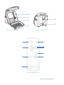
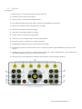
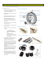
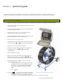
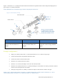
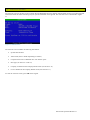
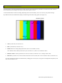
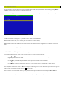
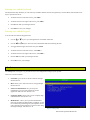
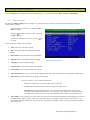
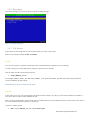
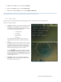
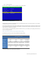
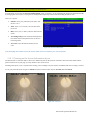
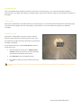
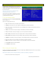
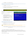
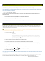
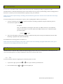
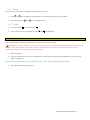
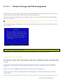
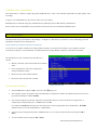
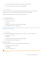
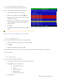
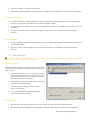
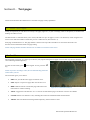
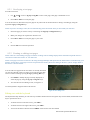
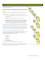
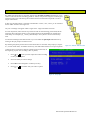
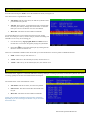
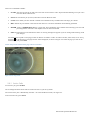
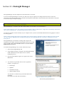
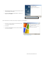
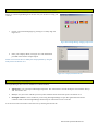
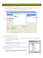
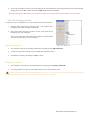
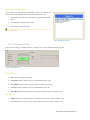
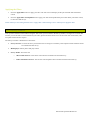
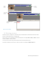
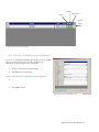
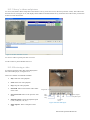
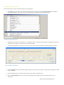
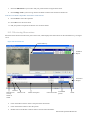
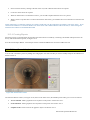

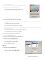
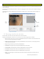
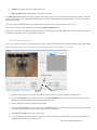
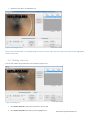
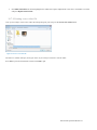
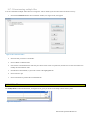
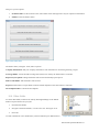
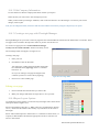
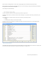
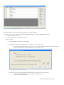
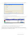
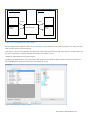
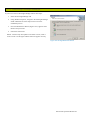
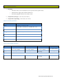
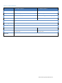

![1 No modo parado, prima [SETUP].](http://vs1.manualzilla.com/store/data/006083259_1-3de954a1ad61f9876a0e4f81f9c2cd22-150x150.png)