1
File and Volume Management
Bull DPS 7000
UFAS-EXTENDED User’s Guide
47 A2 04UF Rev05
File and Volume Management
Bull DPS 7000
UFAS-EXTENDED User’s Guide
Subject:
This manual describes the UFAS-EXTENDED product and
shows how to use it under the GCOS 7 operating system,
Release V7.
Special Instructions:
Software Supported:
GCOS 7 – Release V7.
Software/Hardware required: Software required text
Date:
Bull S.A.
CEDOC
Atelier de reprographie
357, Avenue Patton BP 20845
49008 ANGERS Cedex 01
FRANCE
47 A2 04UF Rev05
June 2001
Bull HN Information Systems Inc.
Publication Order Entry
FAX: (800) 611-6030
MA30/415
300 Concord Rd.
Billerica, MA 01821
U.S.A.
Copyright © Bull S.A., 1995, 2001
Bull acknowledges the rights of proprietors of trademarks mentioned herein.
Your suggestions and criticisms concerning the form, contents and presentation of this manual are invited.
A form is provided at the end of this manual for this purpose.
No part of this publication may be reproduced, stored in a retrieval system or transmitted in any form or by any
means, electronic, mechanical or otherwise without the prior written permission of the publisher.
Bull disclaims the implied warranties of merchantability and fitness for a particular purpose and makes no
express warranties except as may be stated in its written agreement with and for its customer. In no event is Bull
liable to anyone for any indirect, special, or consequential damages.
The information and specifications in this document are subject to change without notice.
Consult your Bull Marketing Representative for product or service availability.
47 A2 04UF Rev05
Preface
Scope and
Objectives
This manual describes UFAS-EXTENDED (Unified File Access System for Large
Systems) and shows how to use it under GCOS7 on DPS7000 machines, with the
latest disk subsystems.
Intended
Readers
The intended readers of this manual are primarily COBOL programmers, but it
may equally be used by programmers working in other languages.
To set up files under GCOS7, a knowledge of GCL (GCOS7 Command Language)
is essential. This information can be obtained from the IOF Terminal User’s
Reference Manual.
Prerequisites
GCL/JCL
To use UFAS-EXTENDED files, you can enter either GCL commands or JCL
statements. Throughout the text, each time a GCL command is given, its functional
equivalent in JCL appears between parentheses. A Correspondence Table is
provided in Appendix D.
Structure
There are eight sections in the manual. Each section begins with a summary. You
should begin by reading the first section which introduces UFAS-EXTENDED and
shows its context within the GCOS7 system. In Section 1, basic concepts are
explained. These concepts are essential reading for anyone who wishes to acquire
background information about UFAS-EXTENDED.
The next three sections describe the three UFAS-EXTENDED file organizations:
sequential, relative and indexed sequential. The type of file organization to be used
within a system is generally an application designer’s decision. This decision is
then translated into the necessary programming language to suit the file
organization. Most likely, you will not need to read all three sections.
The fifth section shows how to assign and reference UFAS-EXTENDED files with
GCL or JCL.
47 A2 04UF Rev05
iii
UFAS-EXTENDED User’s Guide
The sixth section concentrates on file design and shows you how to allocate a
UFAS-EXTENDED file. Parameters to be specified may vary depending on the
particular disk device you use.
The seventh section describes the use of tape files.
The eighth section gives an overview of the utilities for manipulating and
maintaining files.
Use the index to locate a particular topic.
Bibliography
The most important manuals referred to in the text are:
COBOL 85 Reference Manual .................................................................47 A2 05UL
COBOL 85 User’s Guide .........................................................................47 A2 06UL
Data Management Utilities User’s Guide................................................47 A2 26UF
GPL System Primitives ............................................................................47 A2 34UL
UFAS Booster User’s Guide.....................................................................47 A2 33UF
IOF Terminal User’s Reference Manual (Part 1) .................................... 47 A2 38UJ
IOF Terminal User’s Reference Manual (Part 2) .................................... 47 A2 39UJ
IOF Terminal User’s Reference Manual (Part 3) .................................... 47 A2 40UJ
File Migration Tool User’s Guide............................................................47 A2 32UF
File Recovery Facilities User’s Guide .....................................................47 A2 37UF
JCL Reference Manual .............................................................................47 A2 11UJ
JCL User’s Guide..................................................................................... 47 A2 12UJ
Other manuals referred to in the text are:
Catalog Management User’s Guide.........................................................47 A2 35UF
GAC-EXTENDED User’s Guide..............................................................47 A2 12UF
System Administrator’s Manual ............................................................... 47 A2 41US
Full IDS/II Reference Manual 1 ............................................................ 47 A2 05UD
Full IDS/II Reference Manual 2 ............................................................ 47 A2 06UD
Full IDS/II User’s Guide ........................................................................ 47 A2 07UD
Messages and Return Codes Directory.................................................... 47 A2 10UJ
SORT/MERGE Utilities User Guide........................................................47 A2 08UF
TDS Administrator’s Guide......................................................................47 A2 32UT
TDS COBOL Programmer’s Guide..........................................................47 A2 33UT
iv
47 A2 04UF Rev05
Preface
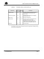
Syntax
Notation
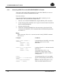
The following conventions are used for presenting GCL command syntax.
ITEM
An item in upper case is a literal value, to be specified
as shown. The upper case is merely a convention; in
practice you can specify the item in upper or lower
case.
item
An item in lower case is a non-literal. A user-supplied
value is expected.
In most cases it gives the type and maximum length of
the value:
char12
a string of up to 12 characters
name31
a name of up to 31 characters
dec10
digits
a decimal integer value of up to 10
file78
characters
a file description of up to 78
volume18
characters
a volume description of up to 18
ITEM
An underlined item is a default value. It is the value
assumed if none is specified.
bool
A boolean value which is either 1 or 0. A boolean
parameter can be specified by its keyword alone,
optionally prefixed by "N". Specifying the keyword
alone always sets the value to 1. Prefixing the keyword
with "N" always sets it to 0.
{}
Braces indicate a choice of items. Only one of these
items can be selected. When presented horizontally,
the items are separated by a vertical bar as follows:
{ item | item | item }
[]
47 A2 04UF Rev05
Square brackets indicate that the enclosed item is
optional. An item not enclosed in square brackets is
mandatory.
v
UFAS-EXTENDED User’s Guide
()
Parentheses indicate that a single value or a list of
values can be specified. A list of values must be
enclosed by parentheses, with each value separated by
a comma or a space.
...
Ellipses indicate that the item concerned can be
specified more than once.
+=$*/-.
Literal characters to be specified as shown.
----
All parameters or commands below a dashed line do
not appear in the help menus.
Example 1:
[ VOLUME = { * | () | (vol18 ...) } ]
This means you can specify:
•
•
•
•
•
Nothing at all (VOLUME=* applies)
VOLUME=* (the same as nothing at all)
VOLUME=FSD001:MS/D500 for a single volume
VOLUME=(FSD001:MS/D500,FSD002:MS/D500) for a list of volumes
VOLUME=() for no volumes
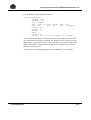
Example 2:
[ ACCNTSPACE = { [+]dec5 | -dec5 } ]
This means you can specify:
•
•
•
•
Nothing at all
ACCNTSPACE=10 to increase the value by 10
ACCNTSPACE=+10 to increase the value by 10
ACCNTSPACE=-10 to decrease the value by 10
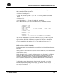
Example 3:
[ AUTOADD ={ bool | 1 } ]
This is a boolean parameter whose default value is one. You can specify:
• Nothing at all (AUTOADD=1 applies)
• AUTOADD=1 or simply AUTOADD
• AUTOADD=0 or simply NAUTOADD
vi
47 A2 04UF Rev05
Table of Contents
1.
2.
3.
Introduction to UFAS-EXTENDED
1.1
Summary ......................................................................................................................... 1-1
1.2
Overview of UFAS-EXTENDED...................................................................................... 1-2
1.3
UFAS-EXTENDED Features........................................................................................... 1-3
1.4
Essential Concepts.......................................................................................................... 1-4
1.4.1 Logical Records ................................................................................................. 1-4
1.4.2 Control Intervals (CIs) ........................................................................................ 1-6
1.4.3 Control Intervals and Address Spaces .............................................................. 1-7
1.4.4 Different Types of Disk Volumes ....................................................................... 1-8
1.4.4.1 FBO Disk Volumes ............................................................................ 1-9
1.4.4.2 VBO Disk Volumes .......................................................................... 1-10
Sequential Organization
2.1
Summary ......................................................................................................................... 2-1
2.2
Brief Review of Sequential Organization ........................................................................ 2-2
2.3
Types of Open Mode....................................................................................................... 2-3
2.4
Type of Access Mode in COBOL-85 ............................................................................... 2-5
2.5
Using a Sequential File for the First Time....................................................................... 2-5
2.6
Format of a Data CI in a Sequential File......................................................................... 2-6
Relative Organization
3.1
Summary ......................................................................................................................... 3-1
3.2
Brief Review of Relative Organization............................................................................. 3-2
3.3
Types of Open Mode....................................................................................................... 3-3
47 A2 04UF Rev05
v
UFAS-EXTENDED User’s Guide
4.
3.4
Types of Access Mode in COBOL .................................................................................. 3-4
3.4.1 Sequential-Access Mode in COBOL-85 ............................................................ 3-4
3.4.2 Random-Access Mode in COBOL-85................................................................ 3-5
3.4.3 Dynamic-Access Mode in COBOL-85 ............................................................... 3-6
3.5
Using a Relative File for the First Time ........................................................................... 3-6
3.6
Format of a Data CI in a Relative File ............................................................................. 3-7
3.7
Example of an Application............................................................................................... 3-9
Indexed Sequential Organization
4.1
Summary ......................................................................................................................... 4-1
4.2
Brief Review of Indexed Sequential Organization........................................................... 4-2
4.3
Types of Open Mode....................................................................................................... 4-5
4.4
Types of Access Mode in COBOL-85 ............................................................................. 4-6
4.4.1 Sequential-Access Mode in COBOL-85 ............................................................ 4-6
4.4.2 Random-Access Mode in COBOL-85................................................................ 4-7
4.4.3 Dynamic-Access Mode in COBOL-85 ............................................................... 4-8
4.5
Using an Indexed Sequential File for the First Time ....................................................... 4-9
4.6
Adding Records............................................................................................................... 4-9
4.7
Deleting Records............................................................................................................. 4-9
4.8
Secondary Keys ............................................................................................................ 4-10
4.8.1 Creating Secondary Indexes ........................................................................... 4-10
4.8.2 Updating Secondary Indexes........................................................................... 4-11
4.9
Structure of a UFAS-Extended Indexed Sequential File............................................... 4-12
4.9.1 Address Space 1.............................................................................................. 4-12
4.9.2 Address Space 2.............................................................................................. 4-12
4.9.3 Address Space 3.............................................................................................. 4-12
4.9.4 Address Space 4.............................................................................................. 4-12
4.9.5 Address Space 5.............................................................................................. 4-13
4.9.6 Address Space 6.............................................................................................. 4-13
4.9.7 Address Space 7.............................................................................................. 4-14
4.9.8 Primary-Index Handling ................................................................................... 4-14
4.9.9 Secondary-Index Handling .............................................................................. 4-16
4.9.10 Structure of a Primary and Secondary Index................................................... 4-17
4.10 Allowing for Free Space ................................................................................................ 4-18
vi
47 A2 04UF Rev05
4.11 Inserting Records .......................................................................................................... 4-19
4.11.1 Simple Insertion ............................................................................................... 4-19
4.11.2 Insertion Requiring CI Compaction.................................................................. 4-20
4.11.3 Insertion Requiring CI Splitting ........................................................................ 4-21
4.11.4 Insertion Requiring Reorganization of Index Cls ............................................. 4-22
4.12 Format of a Data Ci In an Indexed Sequential File ....................................................... 4-24
4.13 Example of an Application............................................................................................. 4-25
5.
File Assignment, Buffer Management, and File Integrity
5.1
Summary ......................................................................................................................... 5-1
5.2
GCL Commands.............................................................................................................. 5-2
5.3
JCL Statements............................................................................................................... 5-3
5.4
User-Program Reference ................................................................................................ 5-4
5.5
File-Assignment Parameter Group ASGi in the GCL Command EXEC_PG .................. 5-5
5.6
Types of Volume ............................................................................................................. 5-8
5.6.1 Resident Volume................................................................................................ 5-8
5.6.2 Work Volume ..................................................................................................... 5-9
5.6.3 Named Volume ................................................................................................ 5-10
5.7
Multivolume Files........................................................................................................... 5-11
5.7.1 Partial/Extensible Processing of Multivolume Files ......................................... 5-12
5.7.2 Managing Multivolume Devices (MOUNT) ...................................................... 5-14
5.8
Sharing Devices between Files (POOL) ....................................................................... 5-16
5.9
File Sharing ................................................................................................................... 5-18
5.10 Overriding Rules............................................................................................................ 5-21
5.11 Using the File-Define Parameter Group DEFi............................................................... 5-23
5.12 Buffer Management....................................................................................................... 5-24
5.12.1 Declaring the Size of the Overall Buffer Space (POOLSIZE).......................... 5-26
5.12.2 Defining a Buffer Pool (BUFPOOL) ................................................................. 5-27
5.12.3 Defining the Number of Buffers (RESERVE AREAS/NBBUF) ........................ 5-29
5.12.4 Examples of Buffer Usage ............................................................................... 5-31
5.12.5 Tuning Buffers.................................................................................................. 5-40
5.12.6 UFAS-EXTENDED Statistics as Presented in the JOR................................... 5-42
5.13 Journalization ................................................................................................................ 5-47
5.13.1 Before Journal.................................................................................................. 5-47
5.13.2 After Journal..................................................................................................... 5-48
47 A2 04UF Rev05
vii
UFAS-EXTENDED User’s Guide
5.14 File Integrity................................................................................................................... 5-50
5.14.1 File Creation..................................................................................................... 5-50
5.14.1.1 Files without Secondary Keys ......................................................... 5-51
5.14.1.2 Files with Secondary Keys .............................................................. 5-51
5.14.2 File Processing ................................................................................................ 5-52
5.14.2.1 INPUT Open Mode .......................................................................... 5-52
5.14.2.2 EXTEND Mode ................................................................................ 5-52
5.14.2.3 Files Without Secondary Keys ........................................................ 5-52
5.14.2.4 Files With Secondary Keys ............................................................. 5-54
5.14.3 File Extension .................................................................................................. 5-55
5.14.4 Permanent I-O Errors....................................................................................... 5-56
6.
viii
Designing and Allocating UFAS-EXTENDED Disk Files
6.1
Summary ......................................................................................................................... 6-1
6.2
Preliminary Remarks ....................................................................................................... 6-2
6.3
What Happens when you Allocate a File ........................................................................ 6-3
6.3.1 Choosing the CI Size (CISIZE) .......................................................................... 6-5
6.3.2 Recommended CI Sizes by Space Occupied.................................................... 6-6
6.3.3 Disk-Storage Capacity ....................................................................................... 6-7
6.3.4 Choosing the Initial Size (SIZE)....................................................................... 6-11
6.3.5 Choosing the Increment Size (INCRSIZE) ...................................................... 6-12
6.4
Simulating File Allocation .............................................................................................. 6-13
6.5
Calculating Space Requirements fir a Sequential File.................................................. 6-14
6.5.1 Fixed-Length Records...................................................................................... 6-14
6.5.2 Variable-Length Records ................................................................................. 6-16
6.6
Calculating Space Requirements for a Relative File..................................................... 6-18
6.7
Design Guidelines for Indexed Sequential Files ........................................................... 6-21
6.7.1 Choosing the CISIZE for an Indexed Sequential File ...................................... 6-22
6.7.2 Choosing Free Space (CIFSP) ........................................................................ 6-22
6.7.3 Mass Insertion.................................................................................................. 6-24
6.7.4 Files With Secondary Keys.............................................................................. 6-24
6.7.5 Calculating Space Requirements .................................................................... 6-25
6.7.5.1 File Without Secondary Indexes...................................................... 6-26
6.7.5.2 File With Secondary Indexes........................................................... 6-30
47 A2 04UF Rev05
6.8
7.
8.
File Allocation Commands ............................................................................................ 6-38
6.8.1 BUILD_FILE..................................................................................................... 6-38
6.8.1.1 Examples of File Allocation Using BUILD_FILE.............................. 6-40
6.8.2 CREATE_FILE................................................................................................. 6-44
6.8.3 The File-Allocation Parameter Group ALCi ..................................................... 6-47
6.8.4 The File-Define Parameter Group DEFi .......................................................... 6-49
6.8.5 LIST_FILE........................................................................................................ 6-52
6.8.6 LIST_FILE_SPACE.......................................................................................... 6-53
6.8.7 MODIFY_FILE ................................................................................................. 6-54
6.8.8 MODIFY_FILE_SPACE ................................................................................... 6-56
Magnetic Tape and Cartridge Tape Files
7.1
Summary ......................................................................................................................... 7-1
7.2
Types of Tape File........................................................................................................... 7-2
7.3
Tape Labels..................................................................................................................... 7-3
7.4
File Attributes .................................................................................................................. 7-4
7.4.1 Record Size (RECSIZE) .................................................................................... 7-4
7.4.2 Block Size (BLKSIZE) ........................................................................................ 7-4
7.4.3 Record Format (RECFORM) ............................................................................. 7-5
7.4.3.1 Fixed-Length Records ....................................................................... 7-6
7.4.3.2 Variable-Length Records................................................................... 7-6
7.5
Choosing the Block Size ............................................................................................... 7-11
7.6
Creating a Magnetic-Tape or a Cartridge-Tape File ..................................................... 7-12
7.7
Referencing Tape Files ................................................................................................. 7-14
7.8
Minimum Length of a Physical Record.......................................................................... 7-16
7.9
Compacted Data On Tape ............................................................................................ 7-16
File Manipulation and Maintenance
8.1
Summary ......................................................................................................................... 8-1
8.2
Sorting and Merging Files ............................................................................................... 8-1
8.3
Load_File......................................................................................................................... 8-2
8.3.1 Converting UFAS Files to the UFAS-EXTENDED File Format ......................... 8-4
8.3.2 Converting VBO files to FBO format.................................................................. 8-5
8.4
Data Services Language (DSL) ...................................................................................... 8-6
8.5
File-Level Utilities ............................................................................................................ 8-7
8.6
Volume-Level Utilities...................................................................................................... 8-9
8.7
Visibility of Physical and Logical Space Allocated to UFAS Disk Files......................... 8-10
47 A2 04UF Rev05
ix
UFAS-EXTENDED User’s Guide
A.
B.
Randomizing Formulas for Relative Files
A.1
Randomizing Techniques................................................................................................A-1
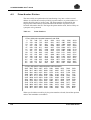
A.2
Prime-Number Division ...................................................................................................A-2
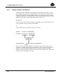
A.3
Square, Enfold, and Extract ............................................................................................A-4
A.4
Radix Conversion ............................................................................................................A-6
A.5
Frequency Analysis .........................................................................................................A-7
A.5.1 Using Frequency Analysis to Develop Randomized Relative Record
Addresses ..........................................................................................................A-9
A.6
Non-Numeric Keys ........................................................................................................A-12
Label and Volume Formats of Magnetic Tapes
B.1
Magnetic-Tape Conventions ...........................................................................................B-1
B.1.1 Reel/File Relationship ........................................................................................B-2
B.1.2 File Organization................................................................................................B-2
B.1.3 Data Organization ..............................................................................................B-2
B.2
Native Magnetic Tape Label and Volume Formats.........................................................B-4
B.2.1 General Information ...........................................................................................B-4
B.2.2 GCOS7/ASCII Standard Format......................................................................B-17
C.
Hexadecimal Layout of Address Spaces in an Indexed Sequential File
D.
JCL - GCL / GCL - JCL Correspondence Tables
E.
More About Buffers
F.
UFAS Files under UFAS-EXTENDED
x
47 A2 04UF Rev05
G.
Batch Performance Improvement
G.1
Overview ........................................................................................................................ G-1
G.1.1 How to Activate the Batch Booster Option........................................................ G-1
G.1.1.1 Activation External to the Program................................................... G-1
G.1.1.2 Activation Within a Program ............................................................. G-2
G.1.2 How BPB Processing Works ............................................................................ G-2
G.2
Conditions for BPB Processing ...................................................................................... G-3
G.3
Support of Data Management Utilities ........................................................................... G-4
G.3.1 File Transfer...................................................................................................... G-4
G.3.2 SORT/MERGE Utilities ..................................................................................... G-4
G.3.2.1 Sort ................................................................................................... G-4
G.3.2.2 Merge ............................................................................................... G-6
G.4
Usage In GCL................................................................................................................. G-6
Index
47 A2 04UF Rev05
xi
UFAS-EXTENDED User’s Guide
xii
47 A2 04UF Rev05
Table of Graphics
Figures
1-1.
1-2.
1-3.
1-4.
1-5.
1-6.
1-7.
1-8.
1-9.
1-10.
2-1.
2-2.
2-3.
2-4.
3-1.
3-2.
3-3.
3-4.
3-5.
3-6.
3-7.
4-1.
4-2.
4-3.
4-4.
4-5.
4-6.
4-7.
4-8.
4-9.
4-10.
4-11.
4-12.
4-13.
Logical Record as Unit of Transfer.................................................................................. 1-5
Control Interval as Unit of Transfer ................................................................................. 1-7
CI Layout in Sequential and Relative Files ..................................................................... 1-7
CI Layout in an Indexed Sequential File ......................................................................... 1-8
Mapping a CI to a Data Block ......................................................................................... 1-9
Disk Track ..................................................................................................................... 1-10
Physical Layout of a VBO Disk Volume ........................................................................ 1-11
Files, Volumes, and Extents.......................................................................................... 1-12
Physical Layout of a File ............................................................................................... 1-12
Logical/Physical Layout of a File................................................................................... 1-13
Layout of Records in a Sequential File ........................................................................... 2-2
Accessing a Sequential File ............................................................................................ 2-3
Format of a data CI in a Sequential File (Fixed-Length Records) .................................. 2-6
Format of a Data CI in a Sequential File (Variable-Length Records) ............................. 2-7
Relative File Record Layout ............................................................................................ 3-2
Sequential Access to a Relative File............................................................................... 3-5
Relative File Random Access ......................................................................................... 3-5
Relative File Dynamic Access......................................................................................... 3-6
Relative File Data CI Format (fixed length records)........................................................ 3-7
Relative File Data CI Format (variable length records)................................................... 3-8
Relative File Application.................................................................................................. 3-9
Indexed Sequential Record Keys.................................................................................... 4-2
Sequential Access to an Indexed Sequential File........................................................... 4-7
Random Access to an Indexed Sequential File .............................................................. 4-7
Dynamic Access to an Indexed Sequential File.............................................................. 4-8
Detailed Layout of an Indexed Sequential File ............................................................. 4-14
UFAS-EXTENDED Indexed File Structure (without secondary keys) ......................... 4-16
Primary and Secondary Index Structure ....................................................................... 4-17
Free Space in an Indexed Sequential File .................................................................... 4-18
Simple Insertion............................................................................................................. 4-19
Insertion Requiring CI Compaction ............................................................................... 4-20
Insertion Requiring CI Splitting...................................................................................... 4-21
Insertion Requiring Reorganization of Index CIs .......................................................... 4-23
Data CI Format in an Indexed Sequential File .............................................................. 4-24
47 A2 04UF Rev05
xiii
UFAS-EXTENDED User’s Guide
5-1.
5-2.
5-3.
5-4.
5-5.
5-6.
5-7.
5-8.
5-9.
5-10.
5-11.
5-12.
5-13.
5-14.
5-15.
5-16.
6-1.
7-1.
7-2.
7-3.
7-4.
7-5.
B-1.
B-2.
E-1.
xiv
Using the File Assignment Parameter Group ................................................................. 5-5
Parameters for Assigning a file (1/2)............................................................................... 5-6
Using Resident Volumes................................................................................................. 5-8
Using a Work Volume ..................................................................................................... 5-9
Using a named volume ................................................................................................. 5-10
Using a Multivolume Uncataloged Disk or Tape File .................................................... 5-11
Using a Multivolume Cataloged File.............................................................................. 5-11
Partial/Extensible Processing of Multivolume Tape Files ............................................. 5-13
Managing Multivolume Devices .................................................................................... 5-15
Pool Device ................................................................................................................... 5-17
Sharing a File with Another Step................................................................................... 5-18
ACCESS and SHARE Values ....................................................................................... 5-19
File-Sharing Rules......................................................................................................... 5-20
Layout of Buffer Space.................................................................................................. 5-25
Using the Before Journal............................................................................................... 5-47
Using the After Journal.................................................................................................. 5-48
Using CIFSP.................................................................................................................. 6-23
Types of Tape File........................................................................................................... 7-2
Fixed-Length Records: Blocked and Unblocked............................................................. 7-6
Variable-Length Records ................................................................................................ 7-7
Variable-Length Unblocked Records .............................................................................. 7-8
Variable-Length Blocked Records................................................................................... 7-9
Magnetic Tape Label Formats Read by GCOS7/EBCDIC (1/2) ...................................B-14
Magnetic Tape Label Formats Accepted by GCOS7/ASCII .........................................B-22
Buffer Handling................................................................................................................E-2
47 A2 04UF Rev05
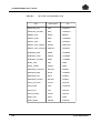
Tables
6-1.
6-2.
6-3.
6-4.
6-5.
8-1.
8-2.
A-1.
A-2.
A-3.
B-1.
B-2.
B-3.
B-4.
B-5.
B-6.
B-7.
B-8.
B-9.
B-10.
B-11.
D-1.
D-2.
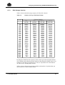
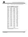
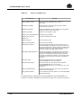
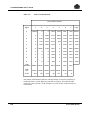
Recommended CISIZE values........................................................................................ 6-6
Number of CIs per FSA Disk Volume.............................................................................. 6-7
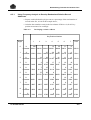
Storage Capacity of Non-FSA Disk Volumes.................................................................. 6-8
Comparative Capacity of VBO and FBO MS/D500 Volumes ......................................... 6-9
Comparative Capacity of VBO and FBO MS/B10 Volumes.......................................... 6-10
File-Level Utilities (1/2).................................................................................................... 8-7
Volume-Level Utilities...................................................................................................... 8-9
Prime Numbers ...............................................................................................................A-2
Pattern of distribution ......................................................................................................A-8
Developing a relative address.........................................................................................A-9
Label Types.....................................................................................................................B-5
Volume Header Label 1 (GCOS7/EBCDIC)....................................................................B-6
File Header Label 1 (GCOS7/EBCDIC) (1/2)..................................................................B-8
File Header Label 2 (GCOS7/EBCDIC) (1/2)................................................................B-10
End-of-File Trailer Label 1 (GCOS7/EBCDIC)..............................................................B-12
End-of-Volume Trailer Label 1 (GCOS7/EBCDIC) .......................................................B-13
Magnetic-Tape Formats Written by GCOS7/EBCDIC ..................................................B-16
8. Volume Header Label 1 (GCOS7/ASCII)..................................................................B-17
File Header Label 1 (GCOS7/ASCII) (1/2) ....................................................................B-18
File Header Label 2 (GCOS7/ASCII) ............................................................................B-20
End-of-File Label 1 (GCOS7/ASCII) .............................................................................B-21
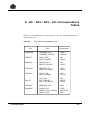
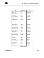
JCL-GCL Correspondence (1/2) .................................................................................... D-1
GCL-JCL Correspondence (1/2) .................................................................................... D-3
47 A2 04UF Rev05
xv
UFAS-EXTENDED User’s Guide
xvi
47 A2 04UF Rev05
1. Introduction to UFAS-EXTENDED
1.1
Summary
This section covers the following topics:
• overview of UFAS-EXTENDED,
• features of UFAS-EXTENDED,
• essential concepts,
− logical records (fixed-length and variable-length),
− control interval (CI),
− control intervals and address spaces,
− layout of CIs within a file,
− FBO disk volumes,
− VBO disk volumes,
disk track
disk cylinder
− disk address,
− disk extent,
− logical/physical layout,
47 A2 04UF Rev05
1-1
UFAS-EXTENDED User’s Guide
1.2
Overview of UFAS-EXTENDED
UFAS-EXTENDED is the standard file structure for DPS 7000 systems. It is the
file structure that is used for applications running under GCOS 7 since release V5.
UFAS-EXTENDED is the interface between logical data management and physical
devices. It is a set of routines providing facilities for:
• creating,
• reading,
• and updating disk and tape/cartridge files known as "UFAS-EXTENDED files".
Regardless of the physical characteristics of the file media, UFAS-EXTENDED
performs the following functions:
•
•
•
•
•
buffer handling,
data blocking,
error checking,
record locating,
label processing.
All CIs (described later in this Section) of a UFAS-EXTENDED file are the same
size.
Fewer I/O operations are performed because of the large number of buffers
supported:
• up to 20,000 buffers per TDS application (18,500 for PREVIOUS files),
• up to 32,000 buffers can be shared at system level, that is, among several
applications, including batch applications.
A large number of files can be simultaneously opened:
• approximately 1000 files can be shared among several TDS applications, if level
of share = 5, or 3200 files if level of share = 2 (with the MI EFM2).
• approximately 500 files can be simultaneously opened for one TDS application.
1-2
47 A2 04UF Rev05
Introduction to UFAS-EXTENDED
1.3
UFAS-EXTENDED Features
The major UFAS-EXTENDED features are as follows:
1.
UFAS-EXTENDED supports the following file organizations:
sequential,
relative,
indexed sequential,
IDS/II (Integrated Data Store).
NOTE:
File organization is the technique of arranging a collection of records in the
most effective way for processing.
An IDS/II file is a database file containing several record types and logical
relationships between them. Physically the file consists of a number of areas.
Since IDS/II is beyond the scope of this manual, please see the relevant IDS/II
Reference Manual for more information, .
2.
Each file organization can be used in the various GCOS 7 environments:
Batch,
Transactional (TDS),
Interactive (IOF).
3.
UFAS-EXTENDED supports the access modes and verbs defined by the
American National Standards Institute (ANSI) for the COBOL Language
(COBOL-85).
4.
Other Features are:
multivolume files (a file spread over several volumes) and multifile volumes
(more than one file per volume) on both disk and tape/cartridge,
standard-label processing on disk, tape, and tape cartridge,
full standard error-handling as defined for COBOL-85,
file integrity through checkpoint/restart and journalization facilities,
concurrent file-access from more than one program,
static and dynamic file extension for sequential and indexed sequential files.
47 A2 04UF Rev05
1-3
UFAS-EXTENDED User’s Guide
1.4
Essential Concepts
The following pages treat concepts which are essential in understanding and using
UFAS-EXTENDED files. These concepts are as follows:
•
•
•
•
logical records,
control intervals (CIs),
control intervals and files,
physical disk characteristics.
The three first concepts only deal with the disk files. The FBO volumes are
defined by the following concepts:
Data Blocks
is the smallest addressable unit for an I/O in a FBO
volume. The size is 512 bytes on a FSA disk and 4096
bytes on a non-FSA disk formatted as a FBO volume.
File Blocks
is the smallest unit that the access method can handle.
The file block corresponds to the CI of the UFAS files.
A file block can consist of one or more data blocks.
Note that files held on tape/cartridge are dealt with separately in Section 7.
1.4.1
Logical Records
Data is transferred between UFAS-EXTENDED and user programs by means of
logical records. These logical records are defined in the program and allow portions
of data to be manipulated. A file is a named collection of these records.
In COBOL, for example, the I-O processing done by verbs such as READ,
WRITE, and REWRITE causes records to be moved to and from a recorddescription area.
In FORTRAN, the record description is the list of variables associated with the I/O
statement.
Records can be of fixed or variable length. This is discussed below.
1-4
47 A2 04UF Rev05
Introduction to UFAS-EXTENDED
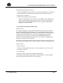
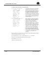
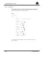
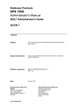
Figure 1-1 shows how the logical record is the unit of transfer between a program
and UFAS-EXTENDED.
GCOS 7
User Programs
System Utilities
Figure 1-1.
Logical
Records
UFAS-EXTENDED
Logical Record as Unit of Transfer
Fixed-Length and Variable-Length Records
Records can be fixed length or variable length. (Fixed length or variable length is
declared as one of the file attributes at file creation time.)
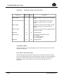
An example of the use of fixed-length records might be in a payroll application,
where there is one record for each employee. The record could have the form:
EMPLOYEE
HOME
SOCIAL
EMPLOYEE
INCOME
NAME
ADDRESS SECURITY N°. NUMBER TAXE CODE
Each employee record contains the same amount of information, therefore each
record is of the same length.
An example of the use of variable-length records might be a sales file in which
there is one record per customer per year. Each customer could theoretically place
an order each week. However, in practice the total number of orders in a year never
exceeds twenty. The design of the record might be:
CUSTOMER
NUMBER
47 A2 04UF Rev05
SALES
AREA
YEAR
ORDER
N°.1
ORDER
N°.2
ORDER
N°.20
1-5
UFAS-EXTENDED User’s Guide
Suppose the average number of orders placed by each customer is 5. It would be
wasteful for each record to contain space for 20 entries (since only 25% of the
space would be used). It is more efficient to use variable-length records, so that
each record will occupy only the necessary amount of space (plus a small amount
of control information, managed by UFAS-EXTENDED).
Under UFAS-EXTENDED, all file organizations support variable-length records.
Note that when variable-length records are used, the maximum record length for
the file is declared at file-allocation time.
1.4.2
Control Intervals (CIs)
One of the most important concepts in UFAS-EXTENDED is the Control Interval
(CI). A CI is the unit of transfer to and from disk. Each CI contains one or more
records, (a minimum of 2 records for indexed sequential files), according to the
size declared by the user. UFAS-EXTENDED CIs correspond to IDS/II pages. The
main characteristics of CIs are:
• All CIs are the same size (data CIs, index CIs or label CIs),
• Records cannot be split across CIs; a CI contains an integral number of records,
•
•
•
•
•
up to a maximum of 255,
The maximum record length cannot exceed the declared CI size,
The maximum size of a CI is 32,256 bytes (32K - 512),
The declared CI size for Fixed Block Organization (FBO) disk subsystems
corresponds to an integral number of blocks (described later in this Section). In
the case of Variable Block Organization (VBO) disk subsystems, the CI size
cannot be larger than one track and CIs do not overflow tracks.
The size of a CI is always a multiple of 512 bytes; you can specify any size for a
CI (up to 5 digits long), but UFAS-EXTENDED always rounds the figure up to a
multiple of 512. Table 6-1 gives you the recommended filling capacity of a CI
for each type of disk drive.
The maximum number of CIs in a file is limited to 16,777,215 (2**24 - 1)
Further information about CIs is contained in the sections specific to each type of
file organization.
1-6
47 A2 04UF Rev05
Introduction to UFAS-EXTENDED
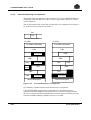
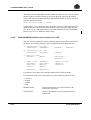
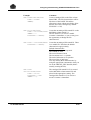
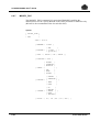
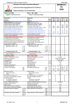
Figure 1-2 shows how the CI is the unit of transfer between UFAS-EXTENDED
and the storage media.
GCOS 7
User Programs
System Utilities
Figure 1-2.
1.4.3
Logical
Records
UFAS-EXTENDED
Control
Interval
Control Interval as Unit of Transfer
Control Intervals and Address Spaces
Read on if you wish to learn more about CIs and the physical characteristics of disk
volumes. The relationship between the logical layout of the file and the physical
layout of the file is discussed. Note that the discussion applies only to disk files;
tape files are discussed in Section 7.
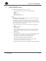
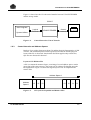
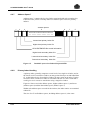
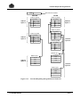
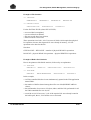
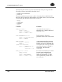
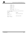
Layout of CIs Within a File
A file is a structured amount of space, consisting of several address spaces used to
group data of the same category. The layout of CIs within a file depends upon the
file organization. Figure 1-3 shows the logical layout of CIs for sequential and
relative files.
Address Space 2
Address
Space 1
Figure 1-3.
47 A2 04UF Rev05
CI
CI
CI
CI
CI
CI
CI
CI Layout in Sequential and Relative Files
1-7
UFAS-EXTENDED User’s Guide
• Address space 1 contains control information such as the description of the other
address spaces and any user labels. This control information is used and
managed by UFAS-EXTENDED, and is always located at the beginning of the
first track used by the file. The address space 1 always occupies one track on a
VBO disk. For FBO volumes, address space 1 occupies a minimum of 16
Kbytes.
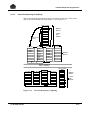
• Address space 2 contains the data CIs.
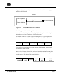
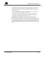
Primary Index CIs
Address
Space 1
Address
Space 3
Figure 1-4.
Address
Space 4
DataCIs
Address
Space 2
Secondary Index CIs
Address
Space 6
Address
Space 7
Address
Space 5
CI Layout in an Indexed Sequential File
• Address space 1 contains control information such as the description of the other
address spaces and any user labels. This control information is used and
maintained by UFAS-EXTENDED. Address space 1 always occupies one disk
track (VBO), or the first sixteen Kbytes of the file (FBO volumes).
• Address space 2 contains the data CIs,
• Address spaces 3 and 4 contain the primary index CIs, and address spaces 5, 6
and 7 contain the secondary index CIs.
The terms primary index and secondary index are defined later in Section 4.
To see how the logical layout described above is mapped onto disks, it is first
necessary to describe briefly the physical characteristics of disks.
1.4.4
Different Types of Disk Volumes
A disk volume is a fixed number of plates mounted one above the other on a
common spindle.
Each plate has two recording surfaces, top and bottom (except the upper surface of
the top disk and the lower surface of the bottom disk, which are protective covers
and are not used for data storage).
The physical disk volume is different from the logical volume. The logical volume
determines the place reservation of the file. There are two types of logical volume:
• FBO (Fixed Block Organization), used since the GCOS 7-V5 release.
• VBO (Variable Block Organization), as used in earlier releases.
1-8
47 A2 04UF Rev05
Introduction to UFAS-EXTENDED
There are two different physical architectures:
• The FSA (Fixed Sector Architecture) disks with FBO organization (MS/FSA
device class).
• The non-FSA or CKD disks (device class: MS/500 or MS/B10),which can be
formatted by the VOLPREP into VBO or FBO volumes.
1.4.4.1
FBO Disk Volumes
FBO disk volumes are either FSA (MS/FSA) disks or non-FSA disks formatted as
FBO format (MS/B10 or MS/D55). These volumes are organized in fixed length
data blocks.
The size of a data block is 512 bytes on the FSA disks and 4096 bytes on the nonFSA, FBO formatted. The size of the CIs (file blocks) is a multiple of 512.
CIs are physically mapped onto the data blocks so that volume space is not wasted.
A CI always occupies an integral number of data blocks.
CI
Figure 1-5.
Mapping a CI to a Data Block
In Figure 1-5, a particular CI is mapped onto 7 data blocks, that is 3584 (512 x 7)
bytes.
47 A2 04UF Rev05
1-9
UFAS-EXTENDED User’s Guide
1.4.4.2
VBO Disk Volumes
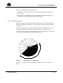
The VBO disk volumes are organized in tracks and cylinders. They are located on
the non-FSA disks using the VBO format (MS/B10 or MS/D500).
Disk Track
Each recording surface is divided into a number of concentric bands, known as
tracks, on which data is recorded. A track is the area covered by one read/write
head during one revolution of the disk. Figure 1-6 illustrates a single track on a
recording surface.
SPINDLE
DISK
1 HEAD
Figure 1-6.
TRAC
Disk Track
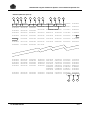
Disk Cylinder
The tracks in the same relative position on each recording surface logically form a
cylinder. For example, the outermost tracks (one from each recording surface) form
one cylinder. Figure 1-7 illustrates cylinders.
Disk Address
A location on a disk volume is specified as:
• a data block address on FBO volumes,
• a cylinder track address on VBO volumes.
Cylinders are numbered consecutively from the outermost (cylinder 000) to the
innermost.
Tracks are numbered according to the recording surface on which they occur. All
tracks on the first recording surface (the lower surface of the top disk) are
numbered 00; all tracks on the second recording surface (the upper surface of the
second disk) are numbered 01, and so on down to the last surface.
1-10
47 A2 04UF Rev05
Introduction to UFAS-EXTENDED
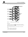
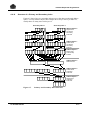
Figure 1-7 illustrates the physical layout and addressing system for disk volumes.
CYLINDER 707
CYLINDER 000
TRACK 00
TRACK 01
TRACK 02
TRACK 03
DISKS
TRACK 04
TRACK 05
TRACK 06
TRACK 07
TRACK 08
TRACK 09
Figure 1-7.
Physical Layout of a VBO Disk Volume
Disk Extents
A disk file can occupy one or more extents. An extent is a group of contiguous
tracks in the case of VBO volumes or in the case of FBO volumes contiguous data
blocks in the same disk volume.
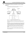
Figure 1-8 illustrates the relationship between disk volumes, files and extents,
where:
• file A is a single-extent, single-volume file.
• file B is a multi-extent, single-volume file.
• file C is a multi-extent, multi-volume file.
47 A2 04UF Rev05
1-11
UFAS-EXTENDED User’s Guide
A
Figure 1-8.
C
B C BC
Files, Volumes, and Extents
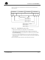
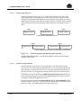
Logical/Physical Layout
Figure 1-9 shows a single file which consists of 4 extents. Extents 1 and 2 are
located on volume X, and extents 3 and 4 are located on volume Y.
Volume X
File
Extent 1
File
Extent 2
File
Extent 3
File
Extent 4
Volume Y
Figure 1-9.
1-12
Physical Layout of a File
47 A2 04UF Rev05
Introduction to UFAS-EXTENDED
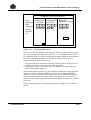
Figure 1-10 shows the relationship between the physical layout and the logical
layout of the file.
File Extent 1
File Extent 2
File Extent 3
File Extent 4
Address Space 2
Address Space 4
Address Space 3
Address Space 1 (1 track)
Address Space 6
Address Space 7
Address Space 5
Figure 1-10.
Logical/Physical Layout of a File
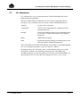
• Address-space boundaries are independent of extent boundaries,
• Address spaces are logically addressed using CI numbers; this means that
UFAS-EXTENDED files can be transferred to a different set of extents without
any special reprocessing,
• You can move UFAS-EXTENDED files between disks with different physical
characteristics (block, number of tracks per cylinder, track capacity) without any
loss of coherence.
Disk-file design and space allocation are described later in Section 6.
47 A2 04UF Rev05
1-13
UFAS-EXTENDED User’s Guide
❑
1-14
47 A2 04UF Rev05
2. Sequential Organization
2.1
Summary
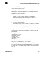
This section covers the following topics:
• sequential-file concepts,
• types of open mode,
• sequential-access mode,
• using a sequential file for the first time,
• format of a data CI in a sequential file.
47 A2 04UF Rev05
2-1
UFAS-EXTENDED User’s Guide
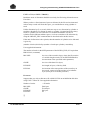
2.2
Brief Review of Sequential Organization
A sequential file can be stored on disk or tape.
Access to the records it contains can only be sequential. To retrieve record n, you
must first read down to and including record (n - 1). After record n has been read,
the next READ statement will read record (n + 1).
NOTE:
In GPL, however, you can access the nth record directly in a sequential disk file,
using this as start point for subsequents READs.
You can write record n only after you have written record (n - 1).
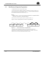
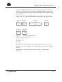
Figure 2-1 shows a logical picture of records in a sequential file.
Rec 1
Rec 2
Figure 2-1.
Rec 3
Rec 4
Rec (n-1)
Rec n
Rec (n+1)
Layout of Records in a Sequential File
A program using a sequential file must have its organization declared as
SEQUENTIAL (ORGANIZATION IS SEQUENTIAL in COBOL). This is the
default value if you omit an ORGANIZATION IS clause.
2-2
47 A2 04UF Rev05
Sequential Organization
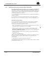
2.3
Types of Open Mode
When you open a file, you must state an open mode, for example in the COBOL
OPEN statement. The declared open mode determines which verbs you can use to
access the file. You can open a sequential file in four modes:
INPUT
OUTPUT
I-O
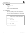
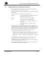
EXTEND (GPL equivalent APPEND)
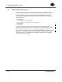
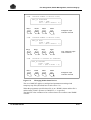
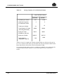
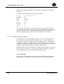
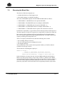
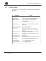
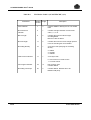
Figure 2-2 shows the ways of opening a sequential file and the verbs used to access
such a file.
COBOL
VERB
COBOL
OPEN MODE
INPUT
READ
REWRITE
X
OUTPUT
I-O*
WRITE
X
X
X
EXTEND
X
*I-O can be applied only to disk files
Figure 2-2.
Accessing a Sequential File
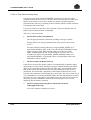
• Opening a file in OUTPUT mode deletes any previous contents of the file; this
mode should normally be used only when you wish to create a new sequential
file,
• EXTEND mode causes the WRITE verb to append extra records to the end of
the file; in all other respects EXTEND mode is equivalent to OUTPUT mode,
• In I-O mode, a REWRITE must be preceded by a READ of the record to be
updated. Do not try to change the length of variable-length records.
47 A2 04UF Rev05
2-3
UFAS-EXTENDED User’s Guide
MULTIVOLUME FILES
(described later in Section 5)
Where space is allocated for a file on more than one volume, volumes are switched
automatically in the OUTPUT, EXTEND, INPUT and I-O open modes as follows:
OUTPUT or EXTEND open modes:
The current volume is released and subsequent write operations continue at the first
allocated extent on the next volume. Note that the first volume must remain on line
because it contains the control information which is required or updated by UFASEXTENDED. The volume switch will occur only when all the allocated space on
the current volume is completely used up.
INPUT and I-O open modes:
After the last record in the last extent of the current volume has been read, the next
record to be read will be the first record on the first extent allocated to the file on
the next volume.
2-4
47 A2 04UF Rev05
Sequential Organization
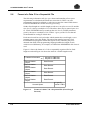
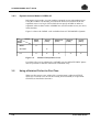
2.4
Type of Access Mode in COBOL-85
You can access a sequential file in only one access mode:
ACCESS MODE IS SEQUENTIAL
In COBOL the access-mode clause must state SEQUENTIAL. This is the default
value.
2.5
Using a Sequential File for the First Time
When you first access a newly allocated sequential file, you should open it in
OUTPUT mode and place records in it. If the file is on disk, it is in fact possible to
open in I-O mode, but this is not advised. You can use such utilities as
LOAD_FILE (JCL equivalent CREATE), SORT_FILE (JCL equivalent SORT),
and MERGE_FILE (JCL equivalent MERGE) as well as COBOL programs.
47 A2 04UF Rev05
2-5
UFAS-EXTENDED User’s Guide
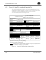
2.6
Format of a Data CI in a Sequential File
The following information will give you a better understanding of how space
requirements are calculated (described later in Section 6). There is no user
programming required to maintain, or take into account, the control fields shown.
UFAS-EXTENDED does all the necessary processing.
Neither fixed-length nor variable-length records are ever split over two CIs and the
size of a CI is always a multiple of 512. Therefore, there may be unused space in a
CI. UFAS-EXTENDED always rounds up the size of a CI (CISIZE parameter)
given by the user to a multiple of 512. Table 6-1 gives you the CI sizes that are
recommended for each type of disk drive.
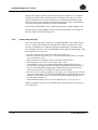
Each stored record has a 4-byte header which contains the record length. A user
program cannot access this header. The unit of data transfer between UFASEXTENDED and programs remains the logical record, containing only userdeclared data fields. Each programming language handles the length of each
variable record differently, for example, in COBOL the DEPENDING ON clause is
used.
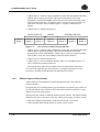
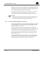
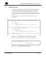
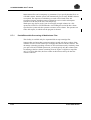
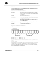
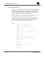
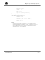
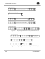
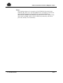
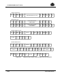
Figure 2-3 shows the format of a CI for a sequentially organized file for fixedlength records and Figure 2-4 shows the same for variable-length records.
CI Header Information
{ 9 bytes for FBO files
{ 8 bytes for VBO files
Record Header
4 bytes
Record Header
4 bytes
Record Header
4 bytes
Record Header
4 bytes
Record Header
4 bytes
Record Header
4 bytes
Unused Space
Figure 2-3.
2-6
Data Record
Data Record
Data Record
Data Record
Data Record
Data Record
1 byte CI
trailer if FBO
Format of a data CI in a Sequential File (Fixed-Length
Records)
47 A2 04UF Rev05
Sequential Organization
CI Header Information
Record Header
4 bytes
Record Header
4 bytes
REC 1
REC 2
Record Header
4 bytes
REC 2
(contd.)
REC 3
and so on up
to record n
Record Header
4 bytes
REC n
Unused Space
Figure 2-4.
47 A2 04UF Rev05
{ 9 bytes for FBO files
{ 8 bytes for VBO files
REC 3
1 byte CI
trailer if FBO
Format of a Data CI in a Sequential File (Variable-Length
Records)
2-7
UFAS-EXTENDED User’s Guide
❑
2-8
47 A2 04UF Rev05
3. Relative Organization
3.1
Summary
This section covers the following topics:
• relative-file concepts,
• types of open mode,
• types of access mode,
• sequential-access mode,
• random-access mode,
• dynamic-access mode,
• using a relative file for the first time,
• format of a data CI in a relative file,
• example of an application,
• advantages and disadvantages.
47 A2 04UF Rev05
3-1
UFAS-EXTENDED User’s Guide
3.2
Brief Review of Relative Organization
A relative file must reside on disk. A record in a relative file can be accessed
directly by its unique record number. To read record n, you do not need to read
through records 1 to (n - 1). Similarly, in OUTPUT, to write record m, you do not
need to write records 1 to (m - 1).
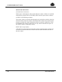
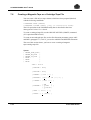
Figure 3-1 shows a logical picture of records in a relative file.
Rec 1
Rec 2
Figure 3-1.
Rec 3
Rec (n-1)
EMPTY
EMPTY
Rec n
Rec (n + 1)
Rec m
Relative File Record Layout
A relative file consists of a series of record positions or slots each of which is
identified by a relative record number (RRN). Each record position, which can
contain one logical record, can be accessed directly via its RRN.
The RRNs are 1, 2, 3,... The maximum record number depends on the size of the
file. If a file is built to hold 1240 records, then the highest RRN is 1240.
When a relative file is first allocated, it consists of empty record positions. Any
attempt to retrieve a record directly from an empty position causes an error.
When the nth record is directly accessed, the record positions 1 to (n - 1) may be
empty. In Figure 3-1, record positions 3 and (n - 1) are empty.
You can establish the RRN either by loading the file sequentially or by converting
a key field into an RRN. Appendix A gives some examples of randomizing
algorithms for key fields.
A program using a relative file must have its organization declared as RELATIVE
(ORGANIZATION IS RELATIVE in COBOL).
3-2
47 A2 04UF Rev05
Relative Organization
3.3
Types of Open Mode
When you open a file, you must state an open mode. You can open a relative file in
four modes:
INPUT
OUTPUT
I-O
EXTEND (GPL equivalent APPEND)
The choice of open mode depends on the access mode declared for the file. The
various combinations are described in the following sections.
47 A2 04UF Rev05
3-3
UFAS-EXTENDED User’s Guide
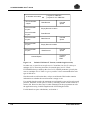
3.4
Types of Access Mode in COBOL
You can access a relative file in three access modes:
{ SEQUENTIAL }
ACCESS MODE IS { RANDOM
}
{ DYNAMIC
}
3.4.1
Sequential-Access Mode in COBOL-85
Sequential-access mode allows the program to carry out standard sequential
processing. The open modes are discussed below.
INPUT mode:
When you open a file in INPUT mode, then the first record read is RRN 1, then
RRN 2 and so on (unless you use the START verb to specify the first record).
Empty record positions are skipped. For example, if record position 4 is empty, the
records read in sequential order are 1,2,3,5,6...
The data name given in the START verb must be the data item that is specified in
the RELATIVE KEY phrase of the associated SELECT clause.
OUTPUT mode:
Opening a file in OUTPUT mode deletes any previous contents of the file. The first
record is written into record position 1, then record position 2, and so on. This is
used only when you wish to initially load a relative file.
I-O mode:
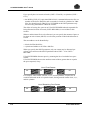
The REWRITE and DELETE verbs must be preceded by a READ verb when
access is sequential. Since the maximum record size is reserved for each record
position, a record written using the REWRITE verb may be of a different length
than the one being overwritten.
EXTEND mode:
The EXTEND phrase can be used only in COBOL-85.
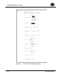
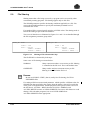
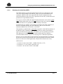
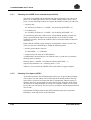
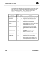
Figure 3-2 shows the COBOL verbs available to the programmer when ACCESS
MODE IS SEQUENTIAL.
3-4
47 A2 04UF Rev05
Relative Organization
COBOL
VERB
OBOL
C
OPEN MODE
READ
I NPUT
WRITE
START
(RRN)
X
X
O UTPUT
X
I-O
X
X
X
X
X
EXTEND
Figure 3-2.
3.4.2
DELETE
REWRITE
Sequential Access to a Relative File
Random-Access Mode in COBOL-85
In random-access mode, each file access must reference a valid RRN specifying
the record position required. The value given in the RELATIVE KEY IS phrase
indicates the record to be accessed.
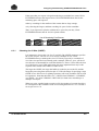
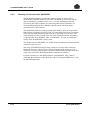
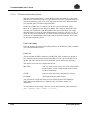
Figure 3-3 shows the COBOL verbs available to the programmer when ACCESS
MODE IS RANDOM.
VERB
OPEN
MODE
INPUT
READ
(RRN)
Figure 3-3.
REWRITE
(RRN)
DELETE
(RRN)
X
X
OUTPUT
I-O
WRITE
(RRN)
X
X
X
X
Relative File Random Access
The difference between WRITE and REWRITE in I-O mode is that a WRITE
statement loads an empty location but REWRITE overwrites an existing valid
record in the file. Since the maximum record size is reserved for each record
position, a record written using the REWRITE verb may be of a different length
than the one being overwritten.
47 A2 04UF Rev05
3-5
UFAS-EXTENDED User’s Guide
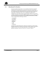
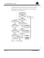
3.4.3
Dynamic-Access Mode in COBOL-85
In dynamic-access mode, you can combine sequential access with random access.
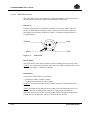
Using the COBOL verb START, you indicate at what record location in the file
sequential access is to begin. Verbs which do not specify an RRN are taken as
sequential, whereas those with a valid RRN are used for random access (see above,
in this Section).
Figure 3-4 shows the COBOL verbs available when ACCESS MODE is dynamic.
OPEN
MODE
VERB
READ
[RRN]
WRITE
[RRN]
REWRITE
[RRN]
DELETE
[RRN]
X
X
INPUT
X
OUTPUT
I-O
X
Figure 3-4.
START
[RRN]
X
X
X
X
Relative File Dynamic Access
If a relative file is to be referenced by a START verb, the RELATIVE KEY phrase
must be specified for that file in the FILE-CONTROL entry.
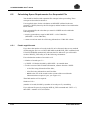
3.5
Using a Relative File for the First Time
When you first access a new relative file, you must open it either in OUTPUT
mode or in I-O mode. You can use the LOAD_FILE command (JCL equivalent
CREATE) as described in Section 8.
3-6
47 A2 04UF Rev05
Relative Organization
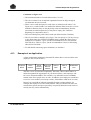
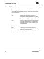
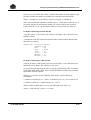
3.6
Format of a Data CI in a Relative File
The following information will help you understand how space requirements are
calculated (described later in Section 6). There is no user programming required to
maintain or take into account the control fields shown. UFAS-EXTENDED does
all the necessary processing. Figure 3-5 shows the CI format for fixed-length
records and Figure 3-6 shows the CI format for variable-length records.
CI Header Information
Record Header
4 bytes
Data Record
Record Header
4 bytes
Empty Record Location
Record Header
4 bytes
Data Record
Record Header
4 bytes
Empty Record Location
Record Header
4 bytes
Data Record
Record Header
4 bytes
Data Record
Unused Space
Figure 3-5.
47 A2 04UF Rev05
{ 9 bytes for FBO files
{ 8 bytes for VBO files
1 byte CI
trailer if FBO
Relative File Data CI Format (fixed length records)
3-7
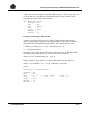
UFAS-EXTENDED User’s Guide
{ 9 bytes for FBO files
{ 8 bytes for non VBO files
CI Header Information
Record Header
4 bytes
Data Record
Record Header
4 bytes
Empty Record Location
Record Header
4 bytes
Data Record
Record Header
4 bytes
Data Record
Record Header
4 bytes
Empty Record Location
Record Header
4 bytes
Data Record
Unused Space
Figure 3-6.
Unused
Space
Unused
Space
Unused
Space
1 byte CI
trailer if
FBO
Relative File Data CI Format (variable length records)
In either case, a record is never split over 2 CIs and the size of a CI is always a
multiple of 512. There may, therefore, be unused space in a CI. UFASEXTENDED always rounds up the size of a CI (CISIZE parameter) given by the
user to a multiple of 512. Table 6-1 gives you the CI sizes recommended for each
type of disk drive.
Note that each record location has a 4-byte record header. This header contains
information on whether the record location is empty or not.
For variable-length records, the maximum record length is reserved for each record
position. Therefore, no file space is saved by choosing variable record format for a
relative file. However, there may be other advantages for the programmer to code
the application using variable-length instead of fixed-length records.
For full details on space calculations, see Section 6.
3-8
47 A2 04UF Rev05
Relative Organization
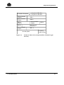
3.7
Example of an Application
A user has a file where each record details a spare part. There are 5,000 spare parts.
The file is to be used on-line as part of a stock control system.
When the file was designed, each spare part was given a number, from 1 to 5,000.
The numbers are published in a catalog used by customers when ordering.
Figure 3-7 shows the ordering procedure.
Spare
Parts
Catalog
Customer Telephones
Order by Using Catalog Number
GCOS 7
Using this Number
Program Addresses
Relative File
Terminal Operator
Keys in Number
Figure 3-7.
Spare
Parts
File
Relative File Application
A file record might have the format:
PART
DESCRIPTION
CURRENT
STOCK
MINIMUM
ORDER
UNIT
PRICE
RE-ORDER
LEVEL
AVAILABILITY
DATE
The user program updates records based on the order value. (The same program
will probably also record the order for billing and shipment.)
Hence, the order is always made using the latest information on stock level and
current price.
The on-line user program would access the file in RANDOM mode. The file would
be opened in I-O mode, to allow changes.
47 A2 04UF Rev05
3-9
UFAS-EXTENDED User’s Guide
If the parts had been numbered in such a way that all parts belonging to a
subassembly were in consecutive record locations, then the user program might
operate in DYNAMIC mode so that a sequential listing of a part of the file could be
made at the terminal.
Each evening, or perhaps once a week, when the on-line operation is not active, a
program might be run which inspects every record in the file in order to compile a
report for replenishing stock items which are at or below the reorder level. Here
access to the file is sequential.
However, even in batch mode, you may find it more efficient to address the file
directly than to perform sequential processing. If a job is run every day to update a
file and if, say, only 2% of the records are accessed in the run, then direct access is
more efficient (in the case above, only 100 records are accessed) rather than
sequential (up to possibly 5000 record accesses). Note that this choice can be made
only if the user program can be supplied with the locations (RRNs) of the records
to be updated.
3-10
47 A2 04UF Rev05
4. Indexed Sequential Organization
4.1
Summary
This section covers the following topics:
• indexed-sequential-file concepts,
• types of open mode,
• types of access mode,
− sequential access,
− random access,
− dynamic access,
• using an indexed sequential file for the first time,
• adding records,
• deleting records,
• secondary keys,
• creating secondary indexes,
• updating secondary indexes,
• structure of a UFAS-EXTENDED indexed sequential file,
− address space 1
− address space 2
− address space 3
− address space 4
− address space 5
− address space 6
− address space 7
• primary-index handling,
• secondary-index handling,
• structure of primary and secondary indexes,
• allowing for free space,
• inserting records,
− simple insertion,
− insertion requiring CI compaction,
− insertion requiring CI splitting,
− reorganization of index CIs.
• format of a data CI in an indexed sequential file,
• example of an application.
47 A2 04UF Rev05
4-1
UFAS-EXTENDED User’s Guide
4.2
Brief Review of Indexed Sequential Organization
An indexed sequential file can reside only on a disk. Each record in an indexed
sequential file is identified by a value called a key. There are two kinds of key:
primary keys and secondary keys.
The primary key is the main key by which a set of records is organized or accessed.
It must be present as a data field within the record and each record may have only
one primary key. Two different records cannot have the same primary key value.
A secondary key is any key, other than the primary key, used to access data. You
can specify up to 15 secondary keys, but they must be present as data fields within
the record. Several different records may have the same secondary key value
(DUPLICATES are allowed), but split keys are not permitted.
Records can be read using the primary or secondary keys. To write a new record or
to update an existing record, the primary key must be used. Figure 4-1 shows a
logical picture of records and their keys in an indexed sequential file.
FIELD 1
FIELD 2
Primary KEY
Figure 4-1.
FIELD 3
FIELD 4
FIELD 5
Secondary KEY
Indexed Sequential Record Keys
For each key, its length and its location within the record must be the same for all
records in the file. The location of the key (that is, its offset from the beginning of
the record) is defined by the user at file-allocation time. Each key is uniquely
identified by its location and its length; this means that no two keys can have the
same location and the same length. This topic is further discussed in Section 6.
Although any two keys must be distinct, it is permissible for them to have the same
KEYLOC (position of the byte of each key in the record).
The key can exist anywhere in the record, subject to the restriction that for
variable-length records the defined key fields must always be present. If a file
contains variable-length records and the highest-key location is byte m and its
length is n bytes, then the minimum length of the record for the file is (m - 1) + n.
CAUTION:
The maximum key length is 251 bytes. It is not possible to have a key split into
several parts.
4-2
47 A2 04UF Rev05
Indexed Sequential Organization
As shown in Figure 1-4, an indexed sequential file has index areas, in addition to
data records. These indexes provide the path between the user-supplied key value
and the address of the record to be accessed. In other words, these indexes are used
to locate records in a data file. UFAS-EXTENDED maintains these indexes.
In the following example, an order file has:
primary key
secondary key
secondary key
= order number
= customer number
= product number
Order
Number
Customer
Number
101
391
0891
QUANTITY
FULL ADDRESS
102
201
0371
QUANTITY
FULL ADDRESS
179
391
0893
QUANTITY
FULL ADDRESS
213
251
0891
QUANTITY
FULL ADDRESS
Duplicates are
not allowed
Product
Number
Duplicates are
allowed
• Customer number 391 has 2 orders (101 and 179) for two different products
(891 and 893).
• Product 891 has been ordered by 2 different customers (391 and 251).
47 A2 04UF Rev05
4-3
UFAS-EXTENDED User’s Guide
Indexes are used in two different ways:
Sequential access:
the order file may be accessed sequentially, that is, in
order number sequence,
Random access:
individual records in the file are accessed on the basis
of a given value for a key; for example, retrieve all the
orders of a customer whose customer number is 391.
A program using an indexed sequential file must have its organization declared as
INDEXED (ORGANIZATION IS INDEXED).
4-4
47 A2 04UF Rev05
Indexed Sequential Organization
4.3
Types of Open Mode
When you open a file, you must state an open mode. You can open an index
sequential file in four modes:
INPUT
OUTPUT
I-O
EXTEND (GPL equivalent APPEND)
EXTEND open mode is a recent feature of UFAS-EXTENDED and is available
only in COBOL-85.
The choice of open mode depends on the access mode declared for the file. The
various combinations are described below.
47 A2 04UF Rev05
4-5
UFAS-EXTENDED User’s Guide
4.4
Types of Access Mode in COBOL-85
You can access an indexed sequential file in three modes:
{ SEQUENTIAL }
ACCESS MODE IS { RANDOM
}
{ DYNAMIC
}
4.4.1
Sequential-Access Mode in COBOL-85
Choose this mode to process all the records of the file. You can open a file for
INPUT, OUTPUT, or I-O mode.
INPUT and I-O mode:
• Records are read by a program in ascending order by primary-key or secondary-
key value. When records are being read using a secondary key where duplicates
(non unique keys) are allowed, duplicate records are read in the same order as
they were written.
• Use the START verb to specify the logical position within the file at which
processing begins.
I-O only:
When using the REWRITE verb, which must be preceded by a READ, you must
not change the primary-key value.
OUTPUT mode:
• Opening a file in OUTPUT mode deletes the previous contents of the file.
• Open a file for OUTPUT to populate the file; this can be done by a utility such
as the LOAD FILE (JCL equivalent CREATE) command (described later in
Section 8), or by a COBOL program.
• Records written by the program must be in ascending order of primary key.
EXTEND mode:
• Available only in COBOL-85.
• Records must be written in ascending order of primary key.
Figure 4-2 shows the COBOL verbs available when ACCESS MODE IS
SEQUENTIAL.
4-6
47 A2 04UF Rev05
Indexed Sequential Organization
COBOL
VERB
COBOL
OPEN MODE
INPUT
READ
WRITE
DELETE
START
(KEY)
X
X
OUTPUT
X
I-O
X
X
X
X
EXTEND
X
Figure 4-2.
4.4.2
REWRITE
Sequential Access to an Indexed Sequential File
Random-Access Mode in COBOL-85
Random access is performed by a key value. To read a record, the user program
supplies the key value (primary key value or secondary key value, if any) of the
required record. To write a record to a file, the program uses the value of the
record’s primary-key field to place a record in the file.
Note that all primary-key values used in a file must be unique.
Figure 4-3 shows the COBOL verbs available when ACCESS MODE IS
RANDOM.
COBOL
VERB
COBOL
OPEN MODE
INPUT
READ
(KEY)
Figure 4-3.
REWRITE
(KEY)
DELETE
(KEY)
X
OUTPUT
I-O
WRITE
(KEY)
X
X
X
X
X
Random Access to an Indexed Sequential File
In I-O mode:
• WRITE is used to add a new record to a file, that is, a new primary-key value.
• REWRITE is used to overwrite an existing record (having the same record
length and the same primary-key value).
47 A2 04UF Rev05
4-7
UFAS-EXTENDED User’s Guide
4.4.3
Dynamic-Access Mode in COBOL-85
In dynamic-access mode, you can mix sequential with random access in the same
program. Using the COBOL verb START, indicate the record location in the file at
which sequential access is to begin. Verbs without key values are taken as
sequential, whereas those with key values are processed for random access as
described in paragraph 4.4.2.
Figure 4-4 shows the COBOL verbs available when ACCESS MODE IS
DYNAMIC.
COBOL
VERB
COBOL
OPEN MODE
INPUT
READ
(KEY)
DELETE
(KEY)
START
(KEY)
X
X
X
Figure 4-4.
REWRITE
(KEY)
X
OUTPUT
I-O
WRITE
(KEY)
X
X
X
X
Dynamic Access to an Indexed Sequential File
Note that the meaning of a WRITE verb in dynamic-access mode depends on how
you open a file.
CAUTION:
When you open the file in OUTPUT or EXTEND mode:
Records written by WRITE statements must be in ascending order of primary
key. This is particularly important when you open the file in EXTEND mode.
When you open the file in I-O mode:
The primary-key value of the record written need not be greater than the primarykey values of records written by previous WRITE statements (you do not have to
write records in ascending order of primary key).
4-8
47 A2 04UF Rev05
Indexed Sequential Organization
4.5
Using an Indexed Sequential File for the First Time
When you first access a new indexed sequential file, you must open it either in
OUTPUT mode or in I-O mode. You can use a utility such as the LOAD FILE
(JCL equivalent CREATE) command as described in Section 8.
It is recommended that you open the file in OUTPUT mode; if any secondary keys
are associated with this file, then run the SORT_INDEX utility (JCL equivalent
SORTIDX) after the file is loaded. In this case, use the APPLY NO-SORTEDINDEX clause in a COBOL step.
4.6
Adding Records
You may add records with new primary-key values to the file, provided that there is
space available. Primary key values in the additional records may be greater than
the highest value or lower than the lowest value already present in the file. The new
values can, of course, also lie between the existing high and low values. When
designing a file, be sure to allocate sufficient file space for later expansion. See
"Choosing Free Space" in Section 6.
4.7
Deleting Records
When you delete records, the space freed can be re-used during later insertions into
the file. For further details, see this later in Section ("Insertion Requiring CI
Compaction").
47 A2 04UF Rev05
4-9
UFAS-EXTENDED User’s Guide
4.8
Secondary Keys
Up to 15 secondary keys can also be used; duplicate key values are allowed for
secondary keys. In a TDS application, there must not be more than 2 or 3
secondary keys. Avoid specifying meaningless duplicates (KEY = SPACE or
ZERO).
4.8.1
Creating Secondary Indexes
Although there are two ways of creating secondary indexes, it is recommended that
you use the first of those below.
• It is assumed that the records to be loaded are already sorted in primary key
order. When you wish to load the file (first time use), you can use:
− either the LOAD_FILE command (JCL equivalent CREATE),
− or a COBOL program (using WRITE verbs) with the APPLY NO-SORTED-
INDEX ON clause and the ALTERNATE RECORD KEY in the SELECT
clause.
After records are initially loaded in an indexed sequential file, use the
SORT_INDEX (SRTIDX) command (JCL equivalent SORTIDX) to sort and
load the secondary indexes.
• UFAS-EXTENDED builds secondary indexes automatically when the file is:
− updated (open in I-O mode),
− created by a COBOL program without using the APPLY NO-SORTED-
INDEX clause (open in OUTPUT mode),
− loaded with the LOAD_FILE command and the parameter ORDER=0 (JCL
equivalent FILELOAD=NORDER in CREATE).
This means that a newly inserted record is immediately available from its
primary key or from any secondary keys.
The simplified format for SRTIDX is as follows:
SRTIDX [ OUTFILE = ] (outfile-file-description)
For example,
S: SRTIDX (SD3.IQS.CUSTOMERS)
where SD3.IQS.CUSTOMERS is the file whose secondary indexes are to be
created. The keys stored in the secondary index are sorted into ascending
order.
4-10
47 A2 04UF Rev05
Indexed Sequential Organization
For further information about this utility, see the IOF Terminal User’s Reference
Manual or the Data Management Utilities User’s Guide for the equivalent JCL
utility SORTIDX.
Secondary indexes will be built automatically if a COBOL program loads a file by
using the WRITE verb when there is no APPLY NO-SORTED-INDEX ON clause
in the I-O-CONTROL Section of the ENVIRONMENT DIVISION. The same is
true if the program opens the file in I-O mode. Note that in these circumstances any
duplicate records will be written in the order in which they are provided (and not
sorted on the primary key as they would be with SORTIDX).
For performance reasons, it is recommended that you use the APPLY NOSORTED-INDEX ON clause when a file is being initially loaded by a COBOL
program in OUTPUT or EXTEND mode. THE APPLY NO-SORTED-INDEX ON
clause is effective only when the file is opened in output mode.
For more information on the APPLY NO-SORTED-INDEX ON clause, see the
COBOL-85 Reference Manual.
4.8.2
Updating Secondary Indexes
Secondary indexes are updated automatically as the records are updated, according
to ANSI COBOL standards; therefore, no user action is required.
47 A2 04UF Rev05
4-11
UFAS-EXTENDED User’s Guide
4.9
Structure of a UFAS-Extended Indexed Sequential File
It is useful to know about the structure of an indexed sequential file because this
knowledge will help you interpret the information given by the LIST_FILE
command (JCL equivalent FILLIST). For instance, if you find that there have been
a lot of CI splits for a particular file, it is time to redefine the file with a larger free
space allocation and rebuild it.
As shown in Figure 1-4, an indexed sequential file consists of up to 7 address
spaces. These are further detailed in Figure 4-5. Address spaces 3, 4, 5, 6 and 7 are
specific to indexed sequential files.
4.9.1
Address Space 1
This address space contains CIs control information for UFAS-EXTENDED.
Address space 1 always occupies at least the first blocks (16 Kbytes) of an FBO
file , or the first track of a VBO file.
4.9.2
Address Space 2
This address space contains user data structured in logical records in the CIs.
4.9.3
Address Space 3
This address space contains a part of the index used to access the data through the
primary key for an indexed sequential file. It contains that part of the index (highlevel index) that does not point to data CIs. It can be empty for a small file using a
single level index.
4.9.4
Address Space 4
This address space contains the part of the index used to access data through the
primary key for an indexed sequential file. Address space 4 contains that part of the
index (low-level index) that points to data CIs.
4-12
47 A2 04UF Rev05
Indexed Sequential Organization
4.9.5
Address Space 5
This address space contains the lowest part of the indexes that are used to access
the data through secondary keys. It is also known as the dense index. An index is
said to be dense because it contains an entry for every stored record in the indexed
file. For each secondary index, there is one entry at this level for each record in the
data area.
For example, if we have 100 records in the file and 3 secondary keys per record,
the number of entries will be 100 x 3 = 300.
Address space 5 exists only for indexed sequential files with secondary keys.
4.9.6
Address Space 6
For each secondary key that has been specified for the file, there is an index with
the same structure as the primary index.
Address Space 6 contains the high-level index associated with each secondary key.
It does the same job for secondary indexes as address space 3 does for primary
indexes. It exists only for indexed sequential files with secondary keys.
47 A2 04UF Rev05
4-13
UFAS-EXTENDED User’s Guide
4.9.7
Address Space 7
Address space 7 contains the low-level index associated with each secondary key.
It does the same job for secondary indexes as address space 4 does for primary
indexes.
Address Spaces
1
3
2
4
6
7
5
CCCCCCCCCCCCCCCCCCC
I I I I I I I I I I I I I I I I I I I
Lowest-level primary index CIs
Higher-level primary index CIs
UFAS-EXTENDED file-control information
Higher-level secondary index CIs
Lowest-level secondary index CIs
Dense level secondary index CIs
Figure 4-5.
4.9.8
Detailed Layout of an Indexed Sequential File
Primary-Index Handling
A primary index generally comprises several levels. In a single-level index, and at
the lowest level of a multi-level index, an entry points directly to an individual data
CI. At the higher levels of a multi-level index, an entry points to an index CI at the
next lower level; a multi-level index is used where the size of a file is such that it
would give rise to excessive search time using a single-level index.
Figure 4-6 shows two index address spaces, higher (address space 3), and lower
(address space 4) and the data address space (address space 2).
Within each address space reserved for the indexes, the index entries are contained
within CIs.
The size of a CI in all address spaces, including address space 2, is the same.
4-14
47 A2 04UF Rev05
Indexed Sequential Organization
The primary index takes into account the order of the records. It consists of only
one entry per data CI corresponding to its record with the highest key value. The
ascending key sequence allows UFAS-EXTENDED to locate keys that are not
included in the index.
• UFAS-EXTENDED builds as many levels of higher index as necessary and at
each level only one CI is inspected for record access.
• Each index entry records the highest primary-key value present in the CI to
which it refers. Hence, in Figure 4-6, using a 3-character key, the highest
primary-key value present in the 17th data CI is EAP.
Assume that the record with the key named JFO is to be retrieved. UFASEXTENDED begins at the highest level of index. Within the highest index CI
(RST), UFAS-EXTENDED starts its search from the JKA entry which points to the
index CI (JKA) in address space 4. This is the lowest-level index. Within this index
CI, UFAS-EXTENDED finds the index entry JKA which points to the 18th data
CI. UFAS-EXTENDED concludes that the record key JFO, if it is present, is in the
18th CI.
47 A2 04UF Rev05
4-15
UFAS-EXTENDED User’s Guide
4.9.9
Secondary-Index Handling
You can specify up to 15 secondary keys for a file. For performance reasons, the
number of secondary keys used in a transactional environment should be small.
The indexes for these keys are held in address spaces 5, 6 and 7, as shown in
Figure 4-5.
Highest Index CI
EAP
Address Space 3
JKA
PNN
RST
Address Space 4
ACC
EUL
KLM
RAA
ADE
FIB
KRR
PNZ
EAP
JKA
NOU
RST
BID
HAA
PNN
REB
LLL
CI 17
CI 19
CI 20
...
CI’s
1 to 16
BUD
HAB
NOP
REA
CCE
GIA
PNN
RFU
EAP
GLL
PLA
RST
...
DEA
JKA
PAA
DIA
JFO
Figure 4-6.
4-16
CI
18
Address Space 2
...
CI’s
21 to n
Data
CIs
...
UFAS-EXTENDED Indexed File Structure
(without secondary keys)
47 A2 04UF Rev05
Indexed Sequential Organization
4.9.10
Structure of a Primary and Secondary Index
Figure 4-7 shows how two secondary indexes access the data area through address
space 5. To keep matters simple, this example shows only 5 entries per index CI;
usually there are many more entries per CI.
Secondary Index 1
Secondary Index 2
Address Space 6
Higher level
non dense
secondary
index CIs
Address Space 7
Lowest level
non dense
secondary
index CI
Address Space 5
Dense level
of secondary
indexes
Address Space 2
Data area CIs
Address Space 4
Lowest level
of primary
index CIs
Address Space 3
Higher level
of primary
index CIs
Figure 4-7.
47 A2 04UF Rev05
Primary and Secondary Index Structure
4-17
UFAS-EXTENDED User’s Guide
4.10
Allowing for Free Space
At allocation time, you can specify the amount of space to be left empty in a CI by
using the CIFSP parameter in the BUILD FILE command (JCL equivalent
PREALLOC) as described in Section 6. When you load the file for the first time in
OUTPUT mode, space will be left empty according to the CIFSP parameter in
order to allow for later record insertions.
Figure 4-8 shows free space left in CIs after the initial loading of the file.
CI 0
CI 1
Figure 4-8.
CI 2
CI 3
CI 4
CI 5
Free Space in an Indexed Sequential File
The shaded areas represent free space.
4-18
47 A2 04UF Rev05
Indexed Sequential Organization
4.11
Inserting Records
Within the space allocated to the file, UFAS-EXTENDED automatically makes
new CIs available to the file as necessary. When a record is to be inserted into a CI,
UFAS-EXTENDED reads the current CI in which the record should be inserted (on
the basis of the primary key). Some of the insertion mechanisms are described in
the following sections.
4.11.1
Simple Insertion
This occurs when enough space is present in the CI without moving records within
the CI. See Figure 4-9.
Key
FLX
record to be inserted
CI (FXX)
CI (FXX)
CI Header Information
CI Header Information
FAB
FAB
FBB
FBB
FDM
FDM
FNQ
FNQ
FNA
FNA
FXX
FXX
FLX
record descriptors
Figure 4-9.
record descriptors
Simple Insertion
Each record in the CI contains a pointer to the next higher record by key value
within the CI. Note that the physical sequence of records within the CI is not the
same as the key sequence. These pointers allow logical chaining of the CIs.
For an explanation of the "record descriptors", see Section 4.
47 A2 04UF Rev05
4-19
UFAS-EXTENDED User’s Guide
4.11.2
Insertion Requiring CI Compaction
This applies when enough space is present in the CI, but UFAS-EXTENDED must
compact the records in the CI in order to retrieve space made available as a result
of record deletion.
The records remain in the same order as before they were compacted. See Figure 410. (Links between records are not shown.)
Key
FPX
record to be inserted
CI (FXX)
CI (FXX)
CI Header Information
CI Header Information
FAB
FAB
FBB
Free Space
FBB
FDM
FDM
Free Space
Free
Space
FXX
FNA
FNQ
FNQ
FPX
Free Space
Record Descriptors
Figure 4-10.
FNA
FXX
Free Space
Record Descriptors
Insertion Requiring CI Compaction
CIs containing variable-length records often need to be compacted.
UFAS-EXTENDED compacts the records in the CI so that all free space is
collected at the end. During the compaction, the new record is inserted. Because
the Cls are compacted and not reorganized as in earlier releases of UFAS, the costs
associated with the updating of address space 5 are avoided.
4-20
47 A2 04UF Rev05
Indexed Sequential Organization
4.11.3
Insertion Requiring CI Splitting
This occurs when the appropriate CI does not contain enough space. This means
that UFAS-EXTENDED must find another CI. See Figure 4-11.
Index CI (SMX)
DBX
GHH
SMX
Address
Space 4
Lowestlevel
Indexes
Space indexentries
CI (DBX)
BLB
DBX
DBA
CI (GHH)
DBZ
ELG
DCZ
GHH
GHA
DCC
EFF
FAB
CI (SMX)
PLX
PRA
PVB
SMX
NER
GHI
CI (free)
Address
Space 2
Record to be inserted
FPA
Before CI Splitting
After CI Splitting
Index CI (SMX)
CI (DBX)
CI (ELG)
CI (SMX)
BLB
DBX
DBA
DBZ
DCC
DCZ
EFF
ELG
PLX
PRA
PVB
SMX
NER
GHI
CI (GHH)
FAB
FPA
GHA
GHH
DBX
ELG
GHH
SMX
Address
Space 4
Lowestlevel
Indexes
Address Space 2
Figure 4-11.
47 A2 04UF Rev05
Insertion Requiring CI Splitting
4-21
UFAS-EXTENDED User’s Guide
Figure 4-11 shows what is known as CI splitting. UFAS-EXTENDED splits the CI
called GHH. After this CI is split, records DBZ, DCC, DCZ, EFF, and ELG, remain
in the old CI (now called CI (ELG) ), but the new record FPA is inserted into the
new CI (GHH) along with records GHH, GHA, and FAB.
Note that there are links between each CI to allow sequential access to take place.
UFAS-EXTENDED automatically manages the spare entries in index CIs;
normally there are many more entries per index CI than appear in this example.
CAUTION:
If a file with secondary indexes using the Deferred Update mechanism is split,
the mechanism is no longer taken into account and return code WDNAV is
issued; instead, the Before Journal takes effect automatically.
4.11.4
Insertion Requiring Reorganization of Index Cls
In the previous paragraph, where we described an insertion causing a CI to be split,
we assumed that there was at least one spare index entry in the lowest level index
in question. When there is no spare index entry, UFAS-EXTENDED uses more
complex mechanisms to insert a record.
The content of the low-level index CI is split into two index CIs. During this
splitting operation, no data record is moved; only index CIs are affected. As a result
of this splitting, an index entry is made in the high-level index (address space 3 or
6). This entry, in turn, can lead to a reorganization of the high-level indexes.
Figure 4-12 shows how a record identified by key 1210 is to be inserted into the
data CI 13, but CI 13 is full; hence the CI needs to be split, but there is no free
entry in address space 4.
In the right-hand column of Figure 4-12, the index CI (1786) is split and there is
room for the index entry 1100. Next the data CI (13) is split; records whose keys
are 1000, 1020, and 1100 are placed in the new data CI (nn) and record 1214
remains in the data CI (13) where the new record 1210 is also placed.
4-22
47 A2 04UF Rev05
Indexed Sequential Organization
1210
Address
Space 3
Record to be inserted
BEFORE
AFTER
Index CI (4312)
Index CI (4312)
CI Header
Key = 0419
Key = 1786
Key = 4312
CI Header
Key = 0419
Key = 1214
Key = 1786
Key = 4312
Free
Address
Space 3
Index CI (1214)
Index CI (1786)
Address
Space 4
CI Header
CI 12 Key = 0613
CI 13 Key = 1214
CI 14 Key = 1316
CI 15 Key = 1786
CI Header
CI 12 Key = 0613
CI 13 Key = 1214
Key = 1100
Free
Index CI (1786)
Address
Space 4
CI Header
CI 14 Key = 1316
CI 15 Key = 1786
Free
Free
Data CI (nn)
Data CI (13)
Address
Space 2
CI Header
1000
1100
1214
1020
CI Header
1000
1020
1100
Address
Space 2
Data CI (13)
CI Header
1210
1214
Figure 4-12.
47 A2 04UF Rev05
Insertion Requiring Reorganization of Index CIs
4-23
UFAS-EXTENDED User’s Guide
4.12
Format of a Data Ci In an Indexed Sequential File
You may find the following information useful for calculating file space. No user
programming is required to maintain, or take into account, the control fields shown
in Figure 4-13. UFAS-EXTENDED does all the necessary processing.
CI Format (fixed-length or variable-length records)
21 bytes for FBO files
CI Header Information
20 bytes for VBO files
Record Header
5 Bytes
Data Record A
Record Header
5 Bytes
Data Record B
Record Header
5 Bytes
Data Record I
Record Header
5 Bytes
Data Record E
Record Header
5 Bytes
Data Record C
Record Header
5 Bytes
Record Header
5 Bytes
RD (E)
Data Record H
Data Record F
RD (D)
RD (F)
RD (H)
RD (G)
RD (C)
RD (I)
RD (B)
RD (A)
1 byte CI
trailer if FBO
Each record descriptor (RD) is 2 bytes long.
Each record header is 5 bytes long.
Indicates unused space, including any space occupied by logically deleted
records which are not yet physical deleted
Figure 4-13.
4-24
Data CI Format in an Indexed Sequential File
47 A2 04UF Rev05
Indexed Sequential Organization
Comments on Figure 4-13
• The maximum number of records allowed in a CI is 255.
• The size of a data CI for an indexed sequential file must be large enough to
accommodate at least 2 records.
• There is one record descriptor for each active or deleted record in the CI. In
Figure 4-13, records D and G are marked for deletion. When records in a CI are
marked for deletion, they are not physically removed immediately; thus the
associated record descriptors may or may not be empty (See "Insertion
Requiring CI Compaction" above.)
• The record descriptors point to the records (an offset from the CI header).
• The CI size will be a multiple of 512 bytes. You can specify a CI of any size (up
to five digits long), but UFAS-EXTENDED always rounds this figure up to a
multiple of 512. Table 6-1 gives you the recommended CI sizes for each nonFSA disk drive. Table 6-2 gives you the recommended CI sizes for files being
allocated on FSA disks.
• For full details concerning space calculation, see Section 6.
4.13
Example of an Application
A large organization maintains a personnel file where there is one record for each
employee. The record format is:
Employee
Name
Home
Address
Social
Security
Number
Next-of-kin
Name &
Address
Date of
Birth
Date of
Hire
Qualification
level
This file is to be accessed non-sequentially. Therefore, choose either relative or
indexed sequential file organization. If you choose relative, each employee will
have to be allocated an RRN. This would be very inflexible because old RRNs
remain in the file as people leave or retire. In addition, new employees would have
to receive a new number (for security reasons, old numbers could not be re-used).
Instead, you can build an indexed sequential file using a unique number, for
example, the employee’s social security number. Thus you need not invent a new
classification system, and space previously occupied by deleted records can be reused by new key values automatically.
47 A2 04UF Rev05
4-25
UFAS-EXTENDED User’s Guide
❑
4-26
47 A2 04UF Rev05
5. File Assignment, Buffer Management, and
File Integrity
5.1
Summary
This section covers the following topics:
•
•
•
•
•
•
•
•
•
•
•
•
•
•
•
47 A2 04UF Rev05
GCL commands/JCL statements,
user-program reference,
file-assignment parameter group ASGi,
types of volume:
− resident,
− work,
− named,
multivolume files:
− partial/extensible processing of multivolume files,
managing multivolume devices (MOUNT),
sharing devices between files (POOL),
file sharing,
overriding rules,
file-define parameter group DEFi,
manipulating buffers:
− POOLSIZE,
− BUFPOOL,
− NBBUF,
− tuning buffers,
− JOR statistics,
journalization:
− Before Journal,
− After Journal,
file integrity,
− file creation,
− file opening,
file extension,
permanent I-O errors.
5-1
UFAS-EXTENDED User’s Guide
5.2
GCL Commands
GCL commands are used to assign and allocate UFAS-EXTENDED files in the
IOF environment.
You can use the following parameters of the GCL command EXEC PG to reference
UFAS-EXTENDED files:
ASGi
assigns a file to a program (described in Section 5),
ALCi
declares space requirements for a temporary or
permanent disk file (described in Section 6). In certain
commands, like COPY_FILE and COMPARE_FILE,
you can allocate a file dynamically by specifying the
DYNALC and ALLOCATE parameters.
DEFi
provides file attributes for the assigned files (described
in Section 6). These attributes can also be introduced
through the INDEF and OUTDEF parameters of a file
management utility.
GCL Keywords:
POOL
optimizes device usage (described in Section 5),
POOLSIZE
defines the maximum size of the UFAS-EXTENDED
buffer pool. (described in Section 5).
These statements are discussed here as they apply to UFAS-EXTENDED files. For
a complete description, see the IOF Terminal User’s Reference Manual.
5-2
47 A2 04UF Rev05
File Assignment, Buffer Management, and File Integrity
5.3
JCL Statements
JCL statements are used to assign and allocate UFAS-EXTENDED files in the
batch and TDS environments.
The files, and the manner in which they are to be used, are specified in the job
description. JCL statements which can reference UFAS-EXTENDED files are:
ASSIGN
assigns a file to a program,
ALLOCATE
declares space requirements for a temporary or new
permanent disk file,
DEFINE
provides file attributes and file usage information, such
as the number of buffers allocated to a file (NBBUF
parameter),
POOL
optimizes device usage,
SIZE
declares the declared working set and the memory area
shared by buffers (POOLSIZE parameter).
These statements are discussed in this manual as they apply to UFAS-EXTENDED
files. For a complete description, see the JCL Reference Manual.
In addition to these JCL statements, there is in the CREATE utility, for example,
the OUTALC parameter for dynamically allocating a file. The INDEF and
OUTDEF parameters provide file attributes to be used by UFAS-EXTENDED. All
these parameters are covered in the Data Management Utilities User’s Guide.
47 A2 04UF Rev05
5-3
UFAS-EXTENDED User’s Guide
5.4
User-Program Reference
COBOL programs are independent of the physical attributes of the files they use. A
COBOL program references an "internal-file-name" with which the real file is
associated at run time (see the next section on file assignment). The program
describes only the logical characteristics of the file to be processed. Examples of
such attributes are:
•
•
•
•
•
record length
record format (fixed or variable)
file organization (sequential, relative or indexed)
access mode.
open mode
In some programming languages, the programmer can declare the number of
buffers or the block size, etc. However, for GCOS7, it is good practice to declare
this information in the GCL or JCL and not in the program. If this advice is
followed, the file characteristics can be altered without changing and re-compiling
the program. As it will be discussed later in this Section, the values defined in the
label override the JCL statements/GCL commands, which, in turn, override the
values declared in the program.
5-4
47 A2 04UF Rev05
File Assignment, Buffer Management, and File Integrity
5.5
File-Assignment Parameter Group ASGi in the GCL Command
EXEC_PG
For each internal-file-name (FILEi) used in a program, there must be a fileassignment parameter group introduced through ASGi.
Disk volume
PLM
User program
Disk volume
PDVA
MUPPRG
FILE
FILE
FA.X
FA.Y
REPORT
EXEC_PG MUPPRG
LIB = MY.LMLIB
FILE1 = IFB
ASG1 = FA.X:PLM:MS/D500
FILE2 = IFA
ASG2 = FA.Y
FILE3 = FX2
ASG3 = SYS.OUT;
Figure 5-1.
Using the File Assignment Parameter Group
The program MUPPRG accesses two disk files, FA.Y on disk volume PDVA and
FA.X on disk volume PLM. A report is produced through the standard SYSOUT
mechanism.
The file FA.X is permanent, uncataloged, and therefore has probably been allocated
(and loaded) in a previous job. It is assumed that the file FA.Y is cataloged; thus it
is unnecessary to specify the device class or the media. Similarly, if the file FA.Y is
a resident or a temporary file, the device class or media need not be specified. If it
is cataloged, it has been made known to the catalog in a previous program or job
through the BUILD_FILE, or CREATE_FILE, or MODIFY FILE_STATUS
commands. The media on which the file resides will be found by GCOS7 in the
catalog.
Figure 5-1 shows a simple form of the file-assignment parameter group ASGi.
Figure 5-2 gives the complete syntax of the parameter group ASGi as it applies to
UFAS-EXTENDED files.
47 A2 04UF Rev05
5-5
UFAS-EXTENDED User’s Guide
EXEC_PG
program-name
FILEi = internal-file-name
ASGi = (external-file-name
}
[
{ WRITE
[
{ READ
}
[ ACCESS = { SPREAD
}
[
{ SPWRITE }
[
{ RECOVERY }
[
{ ALLREAD }
]
]
]
]
]
]
} ]
[
{ NORMAL
[ SHARE = { ONEWRITE } ]
[
{ MONITOR } ]
[
{
} ]
[ NBEFN = {dec3 |ALL } ]
[
{
} ]
[
{
} ]
[ FIRSTVOL = { dec3 |EOF } ]
[
{
} ]
[
{
} ]
[ LASTVOL = { dec3 |EOF } ]
[
{
} ]
[
{ DEASSIGN
[ END = { PASS
[
{ LEAVE
[
{ UNLOAD
}
}
}
}
]
]
]
]
[
{ DEASSIGN
[ ABEND = { PASS
[
{ LEAVE
[
{ UNLOAD
}
}
}
}
]
]
]
]
[ MOUNT = dec3 ]
[
{ NO
} ]
[ POOL = { FIRST } ]
[
{ NEXT } ]
[ DEFER = bool ]
[ OPTIONAL = bool ]
Figure 5-2.
5-6
Parameters for Assigning a file (1/2)
47 A2 04UF Rev05
File Assignment, Buffer Management, and File Integrity
[ CATNOW = { bool
} ]
[
{ ddd
} ]
[ EXPDATE = { yy/dd
} ]
[
{ yy/mm/dd } ]
[
{ 6250 } ]
[ DENSITY = {
} ]
[
{ 1600 } ]
[ VOLWR = { bool |0
Figure 5-2
} ] ) ;
Parameters for Assigning a file (2/2)
For an explanation of these parameters, see the IOF Terminal User’s Reference
Manual.
For cataloged files, the minimum information required by a file-assignment
parameter group ASGi, is the name by which the file is referenced in the program,
that is, the internal-file-name (FILEi parameter of the EXEC_PG command) and
the external-file-name (ASGi parameter).
For uncataloged files, the minimum information required is as follows:
•
•
•
•
the internal-file-name,
the external-file-name,
the disk or tape cartridge volume where the file resides,
the device class.
Volume and device class need not be specified if the file is RESIDENT.
47 A2 04UF Rev05
5-7
UFAS-EXTENDED User’s Guide
5.6
Types of Volume
There are 3 types of volume:
• resident
• work
• named
Each type is described in the following sub-sections.
5.6.1
Resident Volume
When a GCOS7 session begins, the operator can name certain disk volumes as
RESIDENT. These disks are kept on-line for the whole session. If no volume name
and no device class is specified at assignment time (see the ASGi parameter group
in sub-section 5.5), the system assumes that the file is either cataloged or allocated
on these resident volumes; see Figure 5-3.
COMM
’THE NEXT GCL STATEMENT REFERS TO A PREVIOUSLY
ALLOCATED FILE ON A RESIDENT DISK VOLUME OR A
CATALOGED FILE’;
EXEC_PG MYPROGRAM
FILE1 = IFLQ
ASG1 = PY.RMSX;
COMM
’THE NEXT STATEMENT REFERS TO A TEMPORARY FILE
ON A RESIDENT DISK VOLUME’;
EXEC_PG MYPG
FILE1 = INLBNB
ASG1 = TFX.P$TEMPRY;
Figure 5-3.
5-8
Using Resident Volumes
47 A2 04UF Rev05
File Assignment, Buffer Management, and File Integrity
5.6.2
Work Volume
The second type is a WORK volume. Whereas a RESIDENT volume must be a
disk, a WORK volume must be a tape or a cartridge. A WORK volume is a tape
prepared by a utility such as the PREPARE_TAPE (PRPTP) (JCL equivalent
VOLPREP) command.
When the user specifies a WORK volume, the operator will be instructed to mount
a WORK volume for the job at execution time. To write to a work tape, a program
must know whether the tape file is permanent (default) or temporary ($TEMPRY).
If a temporary file is written, the volume remains a WORK tape. However, if a
permanent file is written, the tape volume loses its WORK status to become a
normal named volume; see Figure 5-4.
COMM
’THE FOLLOWING FILE ASSIGNMENT PARAMETER GROUP ASGi
REFERENCES A TEMPORARY FILE ON A WORK TAPE. AT THE
END OF THIS PROGRAM THE TAPE WILL STILL HAVE THE
ATTRIBUTE WORK’;
EXEC_PG MYPROGRAM
FILE1 = INITX
ASG1 = (FIT.PM:WORK:MT/T9$TEMPRY);
COMM
’THE NEXT STATEMENT ESTABLISHES A NEW PERMANENT FILE
ON A WORK VOLUME’;
EXEC_PG MYPG
FILE1 = INQLP
ASG1 = (FIT.PM:WORK:MT:T9 EXPDATE=240);
COMM
’NOTE IN THIS EXAMPLE TWO ASGi PARAMETER GROUPS USING
THE SAME FILENAME FIT.PM.THIS IS ACCEPTED BY GCOS 7
SINCE THE STATUS OF THE FILES IS DIFFERENT;I.E.,
TEMPORARY UNCATALOGED AND PERMANENT UNCATALOGED. THE
NEXT TIME THE USER USES THE PERMANENT FILE FIT.PM,
HE MUST SUPPLY THE PROPER VOLUME NAME (THE VOLUME
NAME OF THE WORK TAPE WHICH IS DISPLAYED IN THE JOB
OCCURRENCE REPORT)’;
Figure 5-4.
47 A2 04UF Rev05
Using a Work Volume
5-9
UFAS-EXTENDED User’s Guide
Work tapes are also used when a tape file overruns the supplied volumes. See
"Multivolume Files" later in this Section.
5.6.3
Named Volume
The third and most usual type of volume declaration is the volume name. Each
standard disk and tape volume has a name. This name, stored on the volume label,
can be set up by the following commands:
PREPARE DISK (PRPD)
labels and formats a disk volume
PREPARE TAPE (PRPTP) labels and formats a tape volume
For a complete explanation of these commands, see the IOF Terminal User’s
Reference Manual (Part 2).
The JCL equivalent for formatting disk and tape volumes is the VOLPREP utility.
COMM
’THE FOLLOWING THREE FILE ASSIGNMENT PARAMETER GROUP
ASGi REFER TO UNCATALOGED FILES ON NAMED VOLUMES’;
EXEC_PG MYPROG
FILE1 = BINB
ASG1 = LM.PL:BD41:MS/D500
FILE2 = BINC
ASG2 = GHAC:1487D:MT/T9$TEMPRY
FILE3 = FRED
ASG3 = XA.BPLQ:TXAMB:MT/T9;
COMM
’NOTE THAT NAMED VOLUMES MAY CONTAIN TEMPORARY OR
PERMANENT FILES THROUGH IT WILL PROBABLY BE AN
INSTALLATION POLICY TO PLACE TEMPORARY TAPE FILES ON
WORK VOLUMES’;
Figure 5-5.
5-10
Using a named volume
47 A2 04UF Rev05
File Assignment, Buffer Management, and File Integrity
5.7
Multivolume Files
A single file may be spread across several volumes. All the volumes for the file
must be of exactly the same type (all disk and same disk type, or all tape). For
information on multivolume files and types of OPEN mode, see section 2.
For a multivolume file, always supply volume names, via ASGi parameters, in the
order they were specified when the file was first allocated on disk or first written
on tape.
The maximum number of volumes allowed for a single file is 10 for a noncataloged file.
COMM
’THE NEXT STATEMENT ASSIGNS A MULTIVOLUME FILE NAMED
MST.PLN’;
EXEC_PG MYPG
FILE1 = FILA
ASG1 = (MST.PLN:11451/11452/11453:MS/D500);
COMM
’THE NEXT STATEMENT ASSIGNS A MULTIVOLUME TAPE FILE WHICH
IS TO BE WRITTEN ON WORK TAPES’;
EXEC_PG MYPROGRAM
FILE1 = FILB
ASG1 = (N.MSTPLN:WORK:MT/T9 EXPDATE = 340);
COMM
’EXPDATE ENSURES THAT THE FILE N.MSTPLN WILL BE RETAINED
FOR 340 DAYS.’;
Figure 5-6.
Using a Multivolume Uncataloged Disk or Tape File
Figure 5-7 shows the form of the above example for a cataloged disk file.
EXEC_PG MYPROGRAM
FILE1 = FILA
ASG1 = MST.PLN;
Figure 5-7.
47 A2 04UF Rev05
Using a Multivolume Cataloged File
5-11
UFAS-EXTENDED User’s Guide
Multivolume files can be temporary or permanent. If you specify that the file is on
a WORK volume, then the system will automatically use as many WORK volumes
as required. The sequence in which they are used will be listed in the Job
Occurrence Report, and these names will then have to be used in subsequent
references to the file (if the file is not temporary).
Work tapes may also be used if you do not supply enough volumes for a file
opened in OUTPUT or EXTEND mode. On reaching the end of the last volume
specified, the system asks the operator to mount a work volume. The operator can
refuse the request, in which case the program is aborted.
5.7.1
Partial/Extensible Processing of Multivolume Files
This facility is available only for sequential disk or tape/cartridge files.
Suppose that you know that a program requires records only from a subset of the
volumes of a file. GCOS7 allows you to supply this subset of all the volumes. The
advantage is that the preceding volumes are not read unnecessarily. Similarly, when
you open a file in EXTEND open mode, you need specify only the volume-name
list starting at the last volume containing records. Figure 5-8 applies to tape files
only. For UFAS disk files, the first volume in the list must always be the first
volume of the file.
5-12
47 A2 04UF Rev05
File Assignment, Buffer Management, and File Integrity
File FNAL.A
LBA
LBB
LBC
LBD
LBE
Program reads records only within volumes LBC and LBD. Does not read to
end-of-file, so LBE is not needed
File HMQC.41
PM1
PM2
PM3
PM4
PM5
PM6
PM4 is the last volume currently used. This file is opened in EXTENDED mode and
any future expansion will occur on reserved volumes PM5 and later, PM6.
File NCU.BX
148
?
File NCU.BX. opened in EXTENDED mode, is to grow using work volumes.
Currently, only one volume, 148, accomodates the file.
If the files FNAL.A, HMQC.41 and NCU.BX are cataloged, the above example
becomes:
EXEC_PG GROFIL
LIB = MY.LIB:MSD:MS/D500
FILE1 = FLA
ASG1 = (FNAL.A FIRSTVOL = 3 LASTVOL = 4)
FILE2 = FLB
ASG2 = (HMQC.41 FIRSTVOL = 4)
FILE3 = FLC
ASG3 = NCU.BX;
Figure 5-8.
47 A2 04UF Rev05
Partial/Extensible Processing of Multivolume Tape Files
5-13
UFAS-EXTENDED User’s Guide
5.7.2
Managing Multivolume Devices (MOUNT)
This facility is available only for sequential disk or tape/cartridge files.
Disk files:
In the examples shown so far, all of the volumes of a
multivolume file will be placed on-line simultaneously.
Therefore a file-assignment parameter group ASGi
referencing 5 volumes will use 5 devices.
The following remark applies only to non-fixed disks.
To reduce the number of devices, use the MOUNT
parameter (for sequential files only) in the fileassignment parameter group ASGi. MOUNT specifies
the maximum number of devices to be used at any one
time for the file. The default value, for disk files, is the
number of volumes.
Tape Files:
To specify the maximum number of tape drives to
accommodate the file, use MOUNT. The most
effective values are MOUNT=1 and MOUNT= 2. The
default value is MOUNT = 1 for tape files.
If MOUNT = 1, then only one tape drive will be
reserved for the file. After a volume is used, the
volume will be replaced by the next volume in
sequence. Although minimizing device reservation,
this technique halts the program while the operator
changes volumes, unless premounting is used on
another device.
If MOUNT = 2, only two tape devices are used for the
file. However, in this case the operator can mount each
volume in advance and volume switching is not
delayed by operator intervention. See Figure 5-9.
5-14
47 A2 04UF Rev05
File Assignment, Buffer Management, and File Integrity
COMM
’MAXIMUM NUMBER OF DEVICES USED’;
EXEC_PG MYPROGRAM
FILE1 = GLBE
ASG1 = (REL.X MOUNT = 4);
MT01
MT02
MT03
MT04
MA1
MA2
MA3
MA4
COMM
4 Magnetic Tape
Units are reserved
’MINIMUM NUMBER OF DEVICES USED’;
EXEC_PG MYPG
FILE1 = GLBE
ASG1 = (REL.X MOUNT = 1);
MT01
MT01
MT01
MA1
MA2
MA3
COMM
MT01
MA4
Only 1 Magnetic Tape
Unit is reserved
’MOUNTING IN ADVANCE BY OPERATOR’;
EXEC_PG PROGRAM
FILE1 = GLBE
ASG1 = (REL.X MOUNT = 2);
MT01
MT02
MT01
MT02
MA1
MA2
MA3
MA4
Figure 5-9.
2 Magnetic Tape
Units are reserved
Managing Multivolume Devices
The use of MOUNT applies to cataloged and permanent uncataloged and
temporary tape files (described later in sub-section 7.2).
When the programmer specifies that a file is on a WORK volume and the file is
multivolume, GCOS7 operates as if MOUNT = 1 is specified.
The MOUNT value continues to have effect when a file overflows onto WORK
volumes.
47 A2 04UF Rev05
5-15
UFAS-EXTENDED User’s Guide
5.8
Sharing Devices between Files (POOL)
The MOUNT parameter optimizes device use for a single file which is
multivolume. A second form of device management concerns the sharing of
devices between files.
In the examples shown so far, all the files referred to by the file-assignment
parameter group ASGi must be on-line when the program starts executing.
Therefore, in Figure 5-8 a total of 6 tape drives must be available. Yet in that
example it may be that the file FNAL.A is completely processed before processing
begins on file HMQC.41. Therefore, it would be better to use the same drives for
both files.
This can be done by specifying a device pool in the POOL parameter of the
EXEC_G command and the POOL parameter of the file-assignment parameter
group ASGi. Both are described in the IOF Terminal User’s Reference Manual
(Part 2).
The device-pool technique depends on the logic of the processing program. When
the program has finished processing a file, the program must signal to GCOS7 that
the file can be de-assigned, causing the devices used to become available. In
COBOL this is done by specifying WITH LOCK in the CLOSE verb.
The program SLICK uses 3 disk files, DF.A, DF.B and DF.C. The file DF.A is
processed before the processing of DF.C begins.
5-16
47 A2 04UF Rev05
File Assignment, Buffer Management, and File Integrity
SLICK
BD14
OPEN
.
.
.
CLOSE
OPEN
.
.
.
CLOSE
DF.A
EX58
BD18
FDFA, FDFB
DF.B
FDFA WITH LOCK
FDFC
FDFB, FDFC
DF.C
EXEC_PG SLICK
LIB = AX.LIB
POOL = 1*MS/D500
FILE1 = FDFA
ASG1 = (DF.A POOL = FIRST)
FILE2 = FDFA
ASG2 = DF.B
FILE3 = FDFC
ASG3 = (DF.C POOL = NEXT);
Figure 5-10.
Pool Device
In Figure 5-10, a device pool consisting of one MS/D500 disk drive is defined.
There are two files to be placed on pool devices - DF.A and DF.C (the POOL
parameter). Only one file with POOL is to be loaded when the program is started DF.A (the FIRST parameter). The file DF.C is not mounted and does not require a
disk drive, until the program opens the file (at which point the single-pool device
will be available). The result is that only two disk drives are used by the program.
Note that the device used by file DF.B is not a member of the pool (no POOL in
ASG2).
In one program, there cannot be more than one pool for each type of device.
In the above example, only one device is pooled. In general a device pool may
contain more than one device. So if either or both disk files DF.A and DF.C were
on two volumes, then the pool parameter would be:
POOL 2*MS/D500
You can specify a device pool for disk and tape device types. The files may be
temporary or permanent. The use of MOUNT with device pools is not restricted.
For complete details on the POOL parameter, see the IOF Terminal User’s
Reference Manual (Part 2). The POOL parameter specified at file assignment is
explained in the same manual.
47 A2 04UF Rev05
5-17
UFAS-EXTENDED User’s Guide
5.9
File Sharing
Sharing means that a file being accessed by a program can be accessed by other
concurrently running programs. File sharing applies only to disk files.
The SHARE parameter specifies the sharing conditions applicable to a file. You
can use the SHARE parameter to specify the maximum permitted level of
concurrent file access.
For cataloged files you need specify only the ACCESS values. The sharing mode is
held in the catalog as part of the file attributes.
Two cases of shared access illustrated in Figures 5-11 and 5-12 are handled through
the file-assignment parameter group ASGi.
EXEC_PG
EXEC_PG
MYPG
FILE1 = IFA
ASG1 = (XP.ML
SHARE = NORMAL
ACCESS = READ)...;
Figure 5-11.
MY
FILE1 = MX
ASG1 = (XP.ML
SHARE = NORMAL
ACCESS = READ)...;
Sharing a File with Another Step
The file XP.ML is referenced by both steps.
Some cases of file sharing are treated below:
NORMAL
Many concurrent readers or one writer per file. Sharing
is controlled at the file level. This is the default value.
ONEWRITE
Many readers and one concurrent writer per file.
Sharing is controlled at the file level.
DANGER:
Do not use SHARE = FREE, (that is, totally free file sharing) for UFASEXTENDED files.
If a cataloged file has an associated parameter which specifies a different value for
SHARE from that specified in the catalog, then the catalog value will override the
value given at assignment time, and the program will be given exclusive access to
the file (that is, ACCESS = READ becomes ACCESS = SPREAD, and
ACCESS=WRITE becomes ACCESS=SPWRITE). Do not use this feature to avoid
sharing a file with other programs, but use ACCESS=SPREAD or
ACCESS=SPWRITE where appropriate.
5-18
47 A2 04UF Rev05
File Assignment, Buffer Management, and File Integrity
Figure 5-12 shows the keyword values for ACCESS and SHARE with their
Keyword Values
Type of Sharing Requested
ACCESS
SHARE
WRITE
NORMAL
Exclusive Use (default value).
SPWRITE
NORMAL
Exclusive Use.
READ
NORMAL
Read a file while several jobs read the file.
SPREAD
NORMAL
Exclusive Read.
READ
ONEWRITE
Read a file while several jobs read the file and one job writes
to the file.
SPREAD
ONEWRITE
Exclusive Read.
WRITE
ONEWRITE
Write to a file while several jobs read the file.
SPWRITE
ONEWRITE
Exclusive Use..
Figure 5-12.
ACCESS and SHARE Values
Figure 5-12 shows the types of sharing that the user may request. Whether sharing
is granted, depends on the current use of the file.
For example, a file already assigned with the values:
ACCESS = READ
and
SHARE = ONEWRITE
may be shared with another job which specifies:
ACCESS = WRITE
and
SHARE = ONEWRITE
GCOS7 does NOT check that the organization of the file supports the mode of
sharing that you requested. Observe the following guidelines.
• you cannot share a file opened in OUTPUT mode, (opening a file in OUTPUT
means that a file is being initially loaded),
• you can share indexed sequential files in ONEWRITE. It is important to note
that when a CI split occurs, the whole file is not locked. This means that there
should be fewer access conflicts. During the CI split, there can be several
readers.
47 A2 04UF Rev05
5-19
UFAS-EXTENDED User’s Guide
File Assignment/sharing with END = PASS
When a file is assigned with END = PASS, the file cannot be assigned to another
job that also passes the file with END = PASS until the file is released by the first
job. This restriction prevents deadlock occurring between the jobs.
Requested ACCESS/SHARE Modes
Current
ACCESS/
SHARE
Modes
WRITE/ SPWRITE/
NORMAL NORMAL
READ/
NORMAL
SPREAD/
NORMAL
READ/
SPREAD/
WRITE/
SPWRITE/
ONEWRITE ONEWRITE ONEWRITE ONEWRITE
READ/
NORMAL
READ
NORMAL
SPREAD *
NORMAL
READ
NORMAL
SPREAD *
NORMAL
SPREAD/
NORMAL
SPREAD *
NORMAL
SPREAD *
NORMAL
SPREAD *
NORMAL
SPREAD *
NORMAL
READ/
ONEWRITE
READ
NORMAL
SPREAD * READ
SPREAD * WRITE
SPWRITE *
NORMAL ONEWRITE NORMAL ONEWRITE ONEWRITE
SPREAD/
ONEWRITE
SPREAD *
NORMAL
SPREAD * SPREAD * SPREAD*
SPWRITE * SPWRITE *
NORMAL ONEWRITE ONEWRITE ONEWRITE ONEWRITE
WRITE/
NORMAL
SPWRITE/
NORMAL
WRITE/
ONEWRITE
SPWRITE *
WRITE
ONEWRITE ONEWRITE
SPWRITE/
ONEWRITE
SPWRITE * SPWRITE *
ONEWRITE ONEWRITE
Figure 5-13.
File-Sharing Rules
Blank entries mean that sharing is denied. Entries marked * mean that sharing is
permitted only to a request from the same step.
5-20
47 A2 04UF Rev05
File Assignment, Buffer Management, and File Integrity
5.10
Overriding Rules
CAUTION:
Avoid giving contradictory values for the various file attributes. Values are
tested, for example that the file opened does not have a record size different
from that declared in the program. In COBOL 85, there are further checks and
ANY mismatch between program and file may lead to an abort with return code
OVRVIOL.
When a program opens a file, sufficient information must be available to UFASEXTENDED for file processing. Such attributes as the CI size (block size on tape
files), record size, record format, number of buffers, must be declared or provided
by default. The sources of this information are as follows:
• The existing file label. No label information is available when:
− you write an output file to tape; see sub-section 7.7,
− you allocate a disk file in the same program using the file-allocation
parameter group ALCi; see Section 6.
For an existing disk or input tape file, any values declared in the label will
override all other values supplied from the program or through the GCL or JCL.
• The file-allocation parameter group ALCi (JCL statement ALLOCATE) and the
file-define parameter group DEFi (JCL statement DEFINE), which may be
associated with a file-assignment parameter group ASGi file reference (JCL
statement ASSIGN).
Any values declared in the GCL or JCL, (for example, number of buffers, or
CISIZE) will override any equivalent value in the program; the file-define
parameter group DEFi is described in sub-sections 5.11 and 6.8.4.
• Attributes from the executing program; the user program provides a complete set
of attributes (usually by default).
Outlined below are the general overriding rules for the define parameters.
General Overriding Rule 1:
Rule 1 applies if the file concerned already exists.
(1)
(2)
(3)
(4)
File label (including the VTOC - Volume Table of Contents for a disk file),
Catalog (for a cataloged file),
Define parameters,
File definition value (for example, the FD in a COBOL program, or the
utility’s implicit value if you are using a system utility).
In Rule 1, (1) overrides (2) which overrides (3) which overrides (4), but see the
warning above.
47 A2 04UF Rev05
5-21
UFAS-EXTENDED User’s Guide
The FPARAM parameter allows you to force the define parameter values which
you enter to override the corresponding values in the file label.
• If FPARAM = 0 (the default value), then for an existing file, the file label
overrides the define parameters.
• If FPARAM = 1, then the define parameters override the file label (for an
existing file). Use this facility only in special cases, for example, the file is nonstandard and/or the file is being reloaded to conform to the characteristics given
via the define parameters.
• FPARAM cannot be used to override the catalog entry information for a
cataloged file.
General Overriding Rule 2:
Rule 2 applies if the file concerned does not exist. Therefore it applies to files
being dynamically created, for example through use of the parameter group ALCi
(JCL equivalent ALLOCATE).
(1) Define parameters,
(2) Default file attributes (automatically provided by the COBOL program or by a
utility),
(3) File definition value (FD).
In Rule 2, (1) overrides (2), which overrides (3), but see the warning above.
There are no default values for the parameters within the file-define parameter
group DEFi (JCL equivalent DEFINE). If you do not enter a value for a file-define
parameter, an effective value will still be derived using the above rules. For
example, the following file attributes are chosen automatically if they are not given
in the DEFi parameter group (JCL equivalent DEFINE):
• CISIZE is set to 2048 bytes (If the CREATE_FILE or CREATE_FILESET
commands are being used, CISIZE is set to 3584 bytes for MS/D500 and
MS/B10 disk devices),
• CIFSP = 0.
The CIFSP parameter can be specified in the DEFi parameter group (JCL
equivalent DEFINE) to modify the amount of free space to be defined for a file
which is dynamically allocated. For more information on how to leave free space in
a file, see sub-section 6.7.2.
5-22
47 A2 04UF Rev05
File Assignment, Buffer Management, and File Integrity
5.11
Using the File-Define Parameter Group DEFi
As explained in the previous sub-section, file attributes defined in the catalog
override those defined in the parameter group DEFi. Thus it is recommended that
you define file attributes in the catalog whenever possible.
If the DEFi parameter is present in the EXEC_PG command (JCL equivalent
DEFINE), it is associated (via the internal-file-name) with a file-assignment
parameter group ASGi (JCL equivalent ASSIGN).
EXEC_PG MYPROGRAM
FILE1 = TFX
ASG1 = JC.JHB ...
DEF1 = (file-define parameters);
Use the DEFi parameter (JCL equivalent DEFINE) to perform the following tasks:
• to specify execution parameters effective only for the current job, for example,
the number of buffers,
• to describe file attributes when:
− a new disk file is being built (file-allocation parameter group ALCi),
− an output tape is written,
− an unlabeled tape file is being read.
• to process non-standard tape file formats.
See below for the format of the file-define parameter group DEFi as applicable to
buffers (the full syntax is given in sub-section 6.8.4). Note that, although it is
possible to specify the type of journalization with DEFi, you are strongly advised
to do this in the catalog.
EXEC_PG MYPROG
FILEi = ifn
ASGi = efn
DEFi = ( [BUFPOOL = name4]
[NBBUF = dec3] )
Note that there are no default values in the file-define parameter group DEFi. The
file-define parameters supplement or override declarations of the program. This
topic was discussed in sub-section 5.10.
For a complete explanation of these parameters, see the IOF Terminal User’s
Reference Manual, Part 2 and the JCL Reference Manual.
47 A2 04UF Rev05
5-23
UFAS-EXTENDED User’s Guide
5.12
Buffer Management
This sub-section presents an overview of buffer management which should help
you to understand what is going on behind the scene when a program executes.
Luckily, the average programmer operates at a fairly abstract level, divorced from
the need to know about buffer addressing. The real drudgery of buffer management
is performed by UFAS-EXTENDED and other software modules with which it
interfaces, for example, the Virtual Memory Manager (VMM).
The use of buffers involves working with large quantities of data in main memory
so that the number of disk accesses can be reduced.
When a CI is requested, it is temporarily held in an area of main storage, known as
a buffer. A good analogy for understanding buffers is to think of them as parking
lots for holding file information in main memory. Whenever possible, COBOL
READ and WRITE statements read from and write to buffers in memory.
If a required CI is already in a buffer, no read operation from disk needs to be
performed. Management of buffers consists in minimizing the number of I/O
operations. You can control the declared buffers through the following three
parameters:
POOLSIZE
BUFPOOL
NBBUF
specified in the EXEC_PG command (JCL equivalent:
SIZE statement)
Specified in the DEFi parameter group, (JCL
equivalent: DEFINE)
Specified in the DEFi parameter group, (JCL
equivalent: DEFINE)
EXEC_PG MYPROG
[SIZE=dec8]
[POOLSIZE = dec8]...
FILE1 = ifn1
ASG1 = efn1
DEF1 = ([BUFPOOL = name4 NBBUF = dec3])
FILE2 = ifn2
ASG2 = efn2
DEF2 = ([BUFPOOL = name4 NBBUF = dec3].
} program level
}
..);
}
}
}file level
}
}
}
The use of large buffer pools is no longer restricted to TDS applications: a new
functionality is provided for heavy batch steps. See the examples in Section 5.12.4
for full details.
The following sections describe the use of buffers as they apply to TDS, batch, and
IOF applications.
5-24
47 A2 04UF Rev05
File Assignment, Buffer Management, and File Integrity
POOLSIZE (max. 20,000 buffers)
Code
Segments
Buffer pool
TDS name
Pseudo buffer
pool, DEFT
Buffer pool
BUFPOOL = name
Data
Segments
Internal
Structure
etc.
Figure 5-14.
.
.
.
.
.
.
.
.
.
.
.
4000
Layout of Buffer Space
Note that it is the ICA attribute of the dimension which guarantees that a step will
have a specified amount of memory available to it. The MINMEM option in the
JCL statement SIZE is no longer meaningful with ARM. Within the total amount of
buffer space allocated through use of the POOLSIZE parameter in the JCL
statement SIZE, the following are set up:
• a pseudo buffer pool, named DEFT (buffers cannot be shared among the files),
• a buffer pool with the same name as the TDS application.
• in appropriate cases, a non-TDS buffer pool with name given by BUFPOOL =
name in the DEFINE statement.
Note that the number of buffers in a job is limited to 20,000. For TDS applications,
buffers are assigned in the main buffer pool, TDS name, using the RESERVE
AREAS CLAUSE. For batch and IOF applications, use the NBBUF parameter of
the JCL statement DEFINE to assign buffers in the other pools. The number of
buffers in a pool should correspond to the total of NBBUF for all the files attached
to the pool.
In the pseudo buffer pool (represented by the broken rectangles), five buffers are
shown.
47 A2 04UF Rev05
5-25
UFAS-EXTENDED User’s Guide
5.12.1
Declaring the Size of the Overall Buffer Space (POOLSIZE)
The maximum total amount of main memory reserved for buffers is specified in the
POOLSIZE parameter. Use this parameter to specify in kilobytes the amount of
main memory in which UFAS-EXTENDED creates and manipulates buffers during
program execution. It must be emphasized that you should specify a much higher
value than the default value (27 Kbytes).
It is recommended that you allocate the total buffer space required (POOLSIZE) in
multiples of 4 Kbytes.
If several buffer pools are declared (described in the next sub-section), then the
POOLSIZE value is the total amount of memory occupied by all the buffer pools.
TDS APPLICATIONS ONLY:
It is recommended that for all TDS applications (including TDS controlled and
non-controlled files), a portion of memory be reserved for all buffer pools
including the pseudo buffer pool known as DEFT.
• Plan on reserving from 20 to 50% or even more of the total memory size for the
allocation of buffers, depending on the type of machine.
• Share the portion of memory reserved for buffers among the different TDS
applications, depending on such factors as the importance of the application and
the number of simultaneities and files.
• Estimate the number of buffers which the buffer pool may hold (developed in
sub-section 5.12.3).
• Adjust the Declared Working Set.
When you increase the value of POOLSIZE, you should correspondingly increase
the declared working set (DWS). Both parameters are specified in the JCL
statement SIZE.
• Adjust the number of buffers to the POOLSIZE value.
The relationship between the POOLSIZE value and the number of buffers is further
developed in sub-section 5.12.3.
5-26
47 A2 04UF Rev05
File Assignment, Buffer Management, and File Integrity
BATCH/IOF APPLICATIONS ONLY:
Use the following formula to calculate an approximate value of the POOLSIZE
parameter:
POOLSIZE = (Average nbpg * 4 Kbytes) * NBBUF
where nbpg is the number of pages needed to hold a CI, that is:
nbpg =
CISIZE
4096
rounded up to a multiple of 4 bytes.
Assume that this formula produces the result of 400 Kbytes for POOLSIZE. Then
you can specify this parameter as follows:
EXEC PG MYPROGRAM
SIZE = 500
POOLSIZE = 400;
5.12.2
Defining a Buffer Pool (BUFPOOL)
Buffer pools reduce the amount of storage allocated to buffers by sharing buffer
space among several files. When a buffer is needed, it is taken from a pool of
available buffers. When UFAS-EXTENDED receives a request to read a certain CI,
it looks to see if one of its existing buffers already contains that CI. If no buffer
contains it, then UFAS-EXTENDED finds from its pool of buffers one that is not
currently in use and loads the contents of the requested CI into it.
Use of buffer pools is recommended whenever possible, particularly in applications
which access many files randomly.
To name a buffer pool, specify the BUFPOOL parameter in the file-define
parameter group DEFi (JCL equivalent DEFINE).
TDS APPLICATIONS ONLY:
A large UFAS-EXTENDED buffer pool can result in substantial performance
improvements:
• up to 50% reduction in the number of I/O operations,
• improved response times.
By default, a TDS application has available:
• one buffer pool for all the TDS-controlled files, whose name corresponds to that
of the TDS application,
47 A2 04UF Rev05
5-27
UFAS-EXTENDED User’s Guide
• a pseudo buffer pool which is automatically provided for the non-controlled
files.
The disadvantage of using the DEFT pseudo buffer pool is that the buffers are not
shared among the non-controlled files such as H_CTLN.
In TDS applications, the use of a single buffer pool (tdsname) is normally
recommended. However, do not include in the common buffer pool files which are
accessed:
• in sequential mode: these files require only a few buffers (two if they are
declared sequential, otherwise about 10 buffers),
• in direct mode if they have only a few CIs: such files should be placed together
in a specific buffer pool for which the number of buffers is equal to the total
number of CIs.
A second buffer pool can also be used for input files containing tables such as the
name and address of customers or the product details in a stock application.
Another possible use concerns indexed sequential files accessed sequentially (to
avoid saturation of the main buffer pool).
You must specify in the DEFi parameter group (JCL equivalent DEFINE) for each
file in a buffer pool:
• the name of the buffer pool (BUFPOOL),
• the number of buffers (NBBUF).
If you omit one of these values, then the default values are as follows:
• the buffer pool is named according to the TDS application (tds-name),
• the number of buffers declared in the "RESERVE n AREAS" clause will apply.
Note that the number of buffers specified in the "RESERVE n AREAS" clause is
the default value for all the buffer pools in a TDS application.
BATCH/IOF APPLICATIONS ONLY:
You can define no buffer pools, or one, or several, although the use of more than
one buffer pool is appropriate only in very rare cases. It is particularly
advantageous to specify a buffer pool for a step randomly accessing more than five
files. If a buffer pool is being used, do not include sequential files in it. Use the
LMC mechanism instead.
5-28
47 A2 04UF Rev05
File Assignment, Buffer Management, and File Integrity
5.12.3
Defining the Number of Buffers (RESERVE AREAS/NBBUF)
When you open a file, UFAS-EXTENDED allocates a number of buffers to
accommodate the CIs transferred from disk. NBBUF specifies the number of
buffers per file. You specify this parameter in the file-define parameter group DEFi
described earlier, or in the JCL equivalent DEFINE.
The minimum number of buffers, for all types of access on all types of
organization, is 1 per file.
The default values for NBBUF are as follows:
• a file accessed in non-sequential access mode has 1 buffer (NBBUF = 1)
• a file accessed in sequential access mode has 2 buffers (NBBUF = 2)
• an indexed sequential file accessed directly has 1 buffer. Additional buffers are
reserved for CI splitting.
• an IDS/II area has 4 buffers.
In dynamic-access mode, UFAS-EXTENDED keeps its buffers in memory as long
as possible.
You may specify a number of buffers:
• either for each individual file,
• or at the level of the buffer pool in which files share buffers.
Whenever possible, it is recommended that you use a buffer pool and that you
specify the same NBBUF value for each file belonging to the same buffer pool.
TDS APPLICATIONS ONLY:
Choose the number of buffers (specified in the RESERVE AREAS clause) so that
the size of the memory reserved for buffers (POOLSIZE) is effectively used. The
maximum number of buffers per TDS application is 20,000. Up to 32,000 buffers
may be defined for the whole system.
Specify an estimated value, such as:
Number of Buffers =
POOLSIZE divided by (No. of pages * 4 Kbytes)
For example, if the CISIZE is 6 Kbytes, then 2 pages are required because each
page occupies 4 Kbytes. Note that the:
No. of pages = CISIZE divided by 4096 rounded up
to a multiple of 4 Kbytes.
47 A2 04UF Rev05
5-29
UFAS-EXTENDED User’s Guide
You can refine your estimate by comparing the figure given for USED SIZE and
POOLSIZE in the JOR. If USED SIZE is less than POOLSIZE, then increase the
number of buffers up to the maximum specified in the RESERVE AREAS clause;
otherwise decrease the value of the POOLSIZE parameter and the declaredworking-set.
If you are using two or more buffer pools, specify the same number of buffers
(NBBUF value in the DEFINE statements) for each file belonging to the same
buffer pool (see the second TDS example in the next sub-section).
BATCH/IOF APPLICATIONS ONLY:
The default values for the buffer parameters mean that each file is allocated 1 or 2
buffers so that:
POOLSIZE >= (no. of pages * number of buffers)
You can override the default NBBUF values by specifying a value in the NBBUF
parameter within the file-define parameter group DEFi (JCL equivalent DEFINE).
It is a good general rule that NBBUF for each file should be not less than 6 plus the
number of secondary indexes. Using this rule for sequential files with several
secondary indexes, instead of the normally recommended 100 buffers, will result in
greatly improved performance.
In the first IOF and batch example, the number of buffers per file is defined on a
file-by-file basis through use of the NBBUF parameter.
5-30
47 A2 04UF Rev05
File Assignment, Buffer Management, and File Integrity
5.12.4
Examples of Buffer Usage
FIRST TDS EXAMPLE: - One buffer pool matching the name of the TDS
application, in this case TSIC.
It is assumed that 1,000 buffers are specified in the "RESERVE n AREAS" clause.
$JOB TDS-EX USER=BULL1;
$JOBLIB SM,TSIC.SMLIB;
STEP TSIC,FILE=(TSIC.LMLIB),REPEAT
DUMP=NO;
SIZE 4500 POOLSIZE=4000;
ASSIGN IFN1 EFN1;
ASSIGN IFN2 EFN2;
ASSIGN IFN3 EFN3;
ASSIGN IFN4 EFN4;
ASSIGN IFN5 EFN5;
ASSIGN IFN6 EFN6;
ASSIGN IFN7 EFN7;
ASSIGN IFN8 EFN8;
ASSIGN IFN9 EFN9;
ASSIGN IFN10 EFN10;
.............................................................
.............................................................
ASSIGN IFN50 EFN50;
ASSIGN IFN51 EFN51;
.............................................................
.............................................................
ASSIGN IFN70 EFN70;
ASG DBUGFILE,TSIC.DEBUG,FILESTAT=CAT,SHARE=DIR;
ASG BLIB,.FORM.BIN,SHARE=DIR,ACCESS=READ;
$ASG H_BJRNL DVC=MS/D500 MD=FSD99 FILESTAT=TEMPRY;
ASG H_FORM,.FORM.OBJET,FILESTAT=CAT
SHARE=MONITOR,ACCESS=READ;
$DEFINE H_CTLM ,JOURNAL=BEFORE;
ENDSTEP;
$ENDJOB;
The average CISIZE is estimated at 3,584 bytes. If the declared POOLSIZE value
for these buffers is 4,000 Kbytes, then the required number of buffers is:
4000 Kbytes divided by 4 Kbytes = 1000 buffers.
NOTE:
The 4000 Kbytes includes the space occupied by the buffers of the noncontrolled files.
47 A2 04UF Rev05
5-31
UFAS-EXTENDED User’s Guide
SECOND TDS EXAMPLE: Using two or more Buffer Pools.
In addition to the main buffer pool (in this case named TSIC), a second buffer pool
named PARA is used by two files.
It is assumed that 1,000 buffers are specified in the "RESERVE n AREAS" clause.
$JOB TDS-EX USER=BULL2;
$JOBLIB SM,TSIC.SMLIB,TSIC.TEST;
STEP TSIC,FILE=(TSIC.LMLIB),REPEAT
DUMP=NO;
SIZE 5000 POOLSIZE=4400;
ASSIGN IFN1 PARAM1;
DEFINE IFN1 NBBUF=100 BUFPOOL=PARA;
ASSIGN IFN2 PARAM2;
DEFINE IFN2 NBBUF=100 BUFPOOL=PARA;
ASSIGN IFN4 EFN4;
ASSIGN IFN5 EFN5;
ASSIGN IFN6 EFN6;
ASSIGN IFN7 EFN7;
ASSIGN IFN8 EFN8;
ASSIGN IFN9 EFN9;
ASSIGN IFN10 EFN10;
.............................................................
.............................................................
ASSIGN IFN50 EFN50;
ASSIGN IFN51 EFN51;
.............................................................
.............................................................
ASSIGN IFN70 EFN70;
ASG DBUGFILE,TSIC.DEBUG,FILESTAT=CAT,SHARE=DIR;
ASG BLIB,.FORM.BIN,SHARE=DIR,ACCESS=READ;
$ASG H_BJRNL DVC=MS/D500 MD=FSD99 FILESTAT=TEMPRY;
ASG H_FORM,.FORM.OBJET,FILESTAT=CAT
SHARE=MONITOR,ACCESS=READ;
$DEFINE H_CTLM ,JOURNAL=BEFORE;
$DEFINE H_CTLN ,BUFPOOL=TSIC;
ENDSTEP;
$ENDJOB;
The average buffer size for the files belonging to the default buffer pool (TSIC) is
estimated at 3,584 bytes.
The two files belonging to the buffer pool PARA have a total number of 100
buffers (the size of the CI is 2048 bytes).The contents of these files will reside in
memory because the buffer pool to which they belong may contain the 100 buffers.
5-32
47 A2 04UF Rev05
File Assignment, Buffer Management, and File Integrity
The global size (POOLSIZE) declared for the buffer pool is 4400 Kbytes. From
this figure must be taken the 400 Kbytes for the PARAM1 and PARAM2 files,
whose 100 buffers are contained in the buffer pool named PARA.. (The amount of
space set aside for these buffers is calculated by multiplying 100 by
4 Kbytes=400 Kbytes.)
The remaining 4000 Kbytes are occupied by the buffer pool TSIC. The number of
buffers is calculated as follows:
4000 Kbytes divided by 4 Kbytes = 1000 buffers.
Note that the non-controlled file H_CTLN is declared in the main buffer pool TSIC
(DEFINE H_CTLN BUFPOOL=TSIC).
FIRST IOF EXAMPLE: No Buffer Pool is Specified
EXEC_PG PG=LMNAME LIB=.LMLIB
SIZE 700 POOLSIZE=1320
FILE1=IFN1 ASG1= EFN1
DEF1=(IFN1 NBBUF=200)
FILE2=IFN2 ASG2= EFN2
DEF2=(IFN2 NBBUF=30)
FILE3=IFN3 ASG3= EFN3
DEF3=(IFN3 NBBUF=50);
When no buffer pool is specified, the pool size is computed as follows.
For each file compute (BUFFER SIZE * NBBUF) and add up the size obtained for
each file.
In this example, a total of 280 buffers is declared.
Assume that the files have the following CISIZE values:
File
EFN1
EFN2
EFN3
CISIZE
2048
3584
6144
Then the POOLSIZE to be specified is:
EFN1
EFN2
EFN3
200 * (2048 rounded up to a multiple of 4 Kbytes)
= (200 * 4 Kbytes) = 800 Kbytes
30 * (3584 rounded up to a multiple of 4 Kbytes)
= (30 * 4 Kbytes) = 120 Kbytes
50 * (6144 rounded up to a multiple of 4 Kbytes)
= (50 * 8 Kbytes) = 400 Kbytes
Total size occupied
47 A2 04UF Rev05
= 1320 Kbytes
5-33
UFAS-EXTENDED User’s Guide
SECOND IOF EXAMPLE: A buffer pool is specified for an IOF application
accessing more than 5 or 6 files.
EXEC_PG PG=LMNAME LIB=.LMLIB
SIZE 500 POOLSIZE=4000
FILE1=IFN1 ASG1= EFN1
DEF1=(IFN1 NBBUF=1000 BUFPOOL=PL01)
FILE2=IFN2 ASG2= EFN2
DEF2=(IFN2 NBBUF=1000 BUFPOOL=PL01)
FILE3=IFN3 ASG3= EFN3
DEF3=(IFN3 NBBUF=1000 BUFPOOL=PL01)
FILE4=IFN4 ASG4= EFN4
DEF4=(IFN4 NBBUF=1000 BUFPOOL=PL01)
FILE5=IFN5 ASG5= EFN5
DEF5=(IFN5 NBBUF=1000 BUFPOOL=PL01)
FILE6=IFN6 ASG6= SEQFILE;
Calculating the POOLSIZE in an IOF application having one buffer pool.
In this example, 1000 buffers are declared in a pool named PL01. The file
SEQFILE is a sequential file and does not belong to this pool.
Assume that the files have the following CISIZE values:
File
EFN1
EFN2
EFN3
EFN4
EFN5
EFN6
CISIZE
2048
3584
6144
6144
3584
2048
If the average buffer size is 4 Kbytes, then the POOLSIZE to be specified is:
(1000 * 4 Kbytes) = 4 Mbytes
The values specified in the following two examples for a batch application are
equally valid for an IOF application; instead of specifying JCL statements, you
must specify the equivalent GCL commands.
5-34
47 A2 04UF Rev05
File Assignment, Buffer Management, and File Integrity
FIRST BATCH EXAMPLE: No buffer pool is present.
$JOB B-EXPLS USER=BULL7 HOLD HOLDOUT;
STEP LMNAME .LM;
SIZE 700 POOLSIZE=600;
ASSIGN IFN1 EFN1;
DEFINE IFN1 NBBUF=20;
ASSIGN IFN2 EFN2;
DEFINE IFN2 NBBUF=30;
ASSIGN IFN3 EFN3;
DEFINE IFN3 NBBUF=50;
ENDSTEP;
$ENDJOB;
You follow the same procedure as that described in the first IOF example.
In this example, 100 buffers are declared. Assume that the files have the following
CISIZE values:
File
EFN1
EFN2
EFN3
CISIZE
2048
3584
6144
The POOLSIZE value to be specified is 600 Kbytes which is calculated as follows:
EFN1
EFN2
EFN3
Total
47 A2 04UF Rev05
20 * (2048 rounded up to a multiple of 4 Kbytes)
(20 * 4 Kbytes) = 80 Kbytes
30 * (3584 rounded up to a multiple of 4 Kbytes)
(30 * 4 Kbytes) = 120 Kbytes
50 * (6144 rounded up to a multiple of 4 Kbytes)
(50 * 8 Kbytes) = 400 Kbytes
= 600 Kbytes
5-35
UFAS-EXTENDED User’s Guide
SECOND BATCH EXAMPLE: A buffer pool is specified for a batch application
accessing more than 5 or 6 files.
$JOB B-EXPLS USER=BULL7;
STEP LMNAME .LM;
SIZE 500 POOLSIZE=400;
ASSIGN IFN1 EFN1;
DEFINE IFN1 NBBUF=100 BUFPOOL=PL01;
ASSIGN IFN2 EFN2;
DEFINE IFN2 NBBUF=100 BUFPOOL=PL01;
ASSIGN IFN3 EFN3;
DEFINE IFN3 NBBUF=100 BUFPOOL=PL01;
ASSIGN IFN4 EFN4;
DEFINE IFN4 NBBUF=100 BUFPOOL=PL01;
ASSIGN IFN5 EFN5;
DEFINE IFN5 NBBUF=100 BUFPOOL=PL01;
ASSIGN IFN6 EFN6;
DEFINE IFN6 NBBUF=100 BUFPOOL=PL01;
ASSIGN IFN7 SEQFILE;
ENDSTEP;
$ENDJOB;
In this example 100 buffers are declared in a buffer pool named PL01.
The file SEQFILE is a sequential file and does not belong to the buffer pool.
The total amount of memory reserved for buffers (POOLSIZE) is equal to the
NBBUF value multiplied by the number of pages.
Assume that the files have the following CISIZE values:
File
EFN1
EFN2
EFN3
EFN4
EFN5
EFN6
CISIZE
2048
3584
6144
6144
3584
2048
If the average CISIZE is 3584, then the POOLSIZE value to be specified is:
100 * (3584 rounded up to a multiple of 4 Kbytes)
= (100 * 4 Kbytes)
= 400 Kbytes
Note that the POOLSIZE value (400 Kbytes) includes the space needed by the two
buffers of the sequential file.
5-36
47 A2 04UF Rev05
File Assignment, Buffer Management, and File Integrity
NOTES:
1.
When different NBBUF values are specified for files belonging to the
same buffer pool, only the highest NBBUF value is taken into account;
hence the convention for specifying the highest NBBUF value for all such
files.
2.
If all the files belonging to the same buffer pool have the same CISIZE, the
average buffer size is equal to:
CISIZE rounded up to a multiple of 4 Kbytes.
For heavy BATCH applications: up to 4000 buffers may be specified for a BATCH
step. Note that up to 32000 buffers are available for the whole system (including all
the TDS and BATCH applications). This functionality may be used for heavy steps
randomly accessing UFAS files. It should drastically decrease the number of
physical IOs.
The following recommendations must be strictly respected to avoid aborts:
Do not launch such BATCH steps while TDS applications are running to avoid
TDS or BATCH aborts with RC=SYSOV when more than 32,000 buffers are
needed.
Specify for the BATCH step a POOLSIZE and a DWS large enough to avoid aborts
with RC=CMWSOV. Gather within the same large BUFFER POOL all the UFAS
files which are not accessed in sequential mode.
POOL SIZE COMPUTATION FOR HEAVY BATCH APPLICATIONS.
The computation of the POOLSIZE will depend on:
• the number of buffers declared for the buffer pool(s): up to 4000 buffers.
• the average buffer size.
NOTE:
For heavy batch steps running during the night, with a low multi-level and large
memory available, it is better to compute the POOLSIZE taking into account
the maximum CISIZE rather than the average.
47 A2 04UF Rev05
5-37
UFAS-EXTENDED User’s Guide
FIRST EXAMPLE: GENERAL CASE.
JOB B-EXPLS USER=BULL7
STEP LMNAME .LM ;
SIZE 45000 POOLSIZE=16000;
ASSIGN IFN1 EFN1;
DEFINE IFN1 NBBUF= 4000 BUFPOOL=PL01;
ASSIGN IFN2 EFN2;
DEFINE IFN2 NBBUF= 4000 BUFPOOL=PL01;
ASSIGN IFN3 EFN3;
DEFINE IFN3 NBBUF= 4000 BUFPOOL=PL01;
ASSIGN IFN4 EFN4;
DEFINE IFN4 NBBUF= 4000 BUFPOOL=PL01;
ASSIGN IFN5 EFN5;
DEFINE IFN5 NBBUF= 4000 BUFPOOL=PL01;
ASSIGN IFN6 EFN6;
DEFINE IFN6 NBBUF= 4000 BUFPOOL=PL01;
ASSIGN IFN7 SEQFILE;
ENDSTEP;
ENDJOB;
In this example, 4000 buffers are specified for the six first files which are accessed
randomly. These files belong to the same buffer pool called PL01. The seventh file,
being sequential, does not belong to the buffer pool called PL01. It has only two
buffers, allocated implicitly.
If all the files have the same CISIZE of 4096 bytes, then the buffer pool size will
be:
(4000 * 4K) = 16000 Kbytes.
5-38
47 A2 04UF Rev05
File Assignment, Buffer Management, and File Integrity
SECOND BATCH EXAMPLE: TWO BUFFERS POOLS ARE SPECIFIED.
It may be useful to declare a second buffer pool, in order to gather together files
having a specific behaviour.
For example, small files having only a few CIs and accessed very often may be
resident in memory.
JOB B-EXPLS USER=BULL7
STEP LMNAME .LM ;
SIZE 60000 POOLSIZE=20000;
ASSIGN IFN1 EFN1;
DEFINE IFN1 NBBUF= 3000 BUFPOOL=PL01;
ASSIGN IFN2 EFN2;
DEFINE IFN2 NBBUF= 3000 BUFPOOL=PL01;
ASSIGN IFN3 EFN3;
DEFINE IFN3 NBBUF= 3000 BUFPOOL=PL01;
ASSIGN IFN4 EFN4;
DEFINE IFN4 NBBUF= 3000 BUFPOOL=PL01;
ASSIGN IFN5 EFN5;
DEFINE IFN5 NBBUF= 3000 BUFPOOL=PL01;
ASSIGN IFN6 EFN6;
DEFINE IFN6 NBBUF= 1000 BUFPOOL=PL02;
ASSIGN IFN7 EFN7;
DEFINE IFN7 NBBUF= 1000 BUFPOOL=PL02;
ENDSTEP;
ENDJOB;
In this example, 4000 buffers have been declared in two pools named PL01 with
3000 buffers, and PL02 with 1000 buffers.
POOL SIZE COMPUTATION WHEN SEVERAL BUFFER POOLS ARE
SPECIFIED.
The pool size to be specified is the total amount of the memory dedicated to each
buffer pool.
If the average buffer size in PL01 is estimated to be 4K, and the average buffer size
in PL02 is estimated to be 8K, then the POOLSIZE to be specified will be :
( 3000 * 4K ) + ( 1000 * 8K ) = 20000K
( for PL01 )
( for PL02 )
47 A2 04UF Rev05
5-39
UFAS-EXTENDED User’s Guide
5.12.5
Tuning Buffers
To avoid wasting resources, you can modify an application’s buffer parameters. The
greater the number of buffers you specify, the fewer the disk I/O operations. The
optimum setting for the buffer-related parameters can only be determined
accurately by testing with different values. The maximum total size of the area
reserved for buffers (POOLSIZE) and the number of buffers defined for the pool
have a major impact on the performance of an application, in particular, TDS
applications. Use the JOR statistics (described in the next sub-section) to verify
how efficient the processing is and then tune the necessary parameters accordingly.
At the end of each step, the following information is printed in the JOR:
• for each UFAS-EXTENDED file and for all the files belonging to the same
buffer pool:
− GETCICOUNT, the total number of CI accesses including label, index and
data CIs.
− HITCOUNT, the number of buffers reused from the buffer pool (no I/O
operation required).
• for the whole step:
− Number of buffers deleted (SEGDL)
− Number of buffers created (SEGCR)
To make the best use of buffers, UFAS-EXTENDED may create a buffer, reactivate an existing buffer ("remember" buffer), or delete a buffer. For further
information on how UFAS-EXTENDED handles buffers, see Appendix E.
You can observe how the values affecting buffers work in practice by studying the
JOR statistics.
By adjusting the number of buffers in direct relation to the size of the area reserved
(POOLSIZE), it is possible to achieve the most efficient buffer use, in other words
the highest hit ratio. A hit is the number of CI accesses involving no physical I/O
operation. The hit ratio is the number of existing CIs accessed in the buffer pool to
the total number of CIs accessed (buffer pool and physical I/O operations).
5-40
47 A2 04UF Rev05
File Assignment, Buffer Management, and File Integrity
Tune application programs as follows:
• Choose the NBBUF value for each file, or for the whole buffer pool, so that the
maximum number of buffers already allocated to the buffer pool is reused.
• The hit ratio is defined as:
• HITCOUNT divided by GETCICOUNT
− Choose the POOLSIZE value in relation to the NBBUF value. Adding more
buffers can significantly reduce disk access times. The trade-off is that you
must specify a large enough POOLSIZE value. Normally, USED SIZE is
slightly less than POOLSIZE.
Creation/Deletion of Buffers Within a Step
Buffer Creation
New buffers continue to be created until either the maximum number of buffers
(given in the RESERVE AREAS clause), or the maximum total amount of main
memory reserved for buffers (POOLSIZE) is reached. When one of these limits is
reached, UFAS-EXTENDED uses a previously created buffer, provided the
existing buffers are not busy, or are not used for DEFERRED UPDATES.
Otherwise UFAS-EXTENDED will delete one or more of the existing buffers to
make space available for new buffer(s).
The SEGCR counter indicates the number of buffers which are created for the step.
This number also includes about 5 control structures created at file opening time.
Buffer Deletion
A buffer is deleted:
• when no existing buffer of the same size as the requested one can be re-used,
• when files are closed,
• at a checkpoint,
• at the end of the step (normal or abnormal termination).
The SEGDL counter indicates the number of deleted buffers. Note that SEGDL
does not include the deletion of the control structures.
47 A2 04UF Rev05
5-41
UFAS-EXTENDED User’s Guide
When the value for POOLSIZE and the number of buffers are correctly set, ensure
that the number of buffers created (given by the SEGCR counter in the JOR) is
close to the number of buffers defined in the RESERVE AREAS clause. The most
efficient operation is when:
SEGCR divided by number of buffers
is approaching 1 for a batch step and is the lowest value for a TDS application. To
optimize this ratio, ensure that as many CISIZE values as possible have the same
size. However, in a TDS application, it is recommended that UFAS-EXTENDED
files have up to 3 or 4 different CISIZE values.
5.12.6
UFAS-EXTENDED Statistics as Presented in the JOR
This sub-section explains the statistics that may appear in the JOR. To ensure that
the buffer pool is being properly used, it is important to check these statistics.
>>> IFN=<internal file name>
REWRITECNT=a
DELETECNT=b
WRITECNT=c
>>> EFN=<external file name>
GETCICOUNT=e
HITCOUNT=f
IOCOUNT=g
==> POOL=<pool name>
NBFILES=h
NBBUF=i
>>> XUFAS
STEP
POOLSIZE=l
AVAIL CI=p
SEGCR=s
READIOCT=u
STATISTICS
USED SIZE=m
FREE CI=q
SEGDL=t
READCNT=d
GETCICOUNT=j
HITCOUNT=k
STEP=<step name>
NBPOOLS=n
TOTAL CI=r
WRITEIOCT=v
File Statistics are displayed for both the internal and external file names.
For each internal file name, IFN statistics give the number of logical records:
•
•
•
•
5-42
rewritten
deleted,
written,
read.
REWRITECNT
indicates the number of records rewritten to the
internal file in question.
DELETECNT
indicates the number of records deleted from the
internal file
47 A2 04UF Rev05
File Assignment, Buffer Management, and File Integrity
1
WRITECNT
indicates the number of records written to the internal
file
READCNT
indicates the number of records read in the internal file
3 IMPORTANT:
3
In COBOL 85, if you rewrite a record with a length different from the length of
the existing record in the file, the rewrite operation is treated as a record
deletion followed by a record insertion. Consequently, the number of records
deleted from and written to the file is reflected in the DELETECNT and
WRITECNT counters, and not in the REWRITECNT counter.
IFN statistics are not displayed for IDS areas because IDS uses specific verbs such
as SEARCH and STORE.
For each external file name, EFN statistics give three counters concerning the
number of all CIs accessed.
GETCICOUNT
is the total number of accesses to CIs which are either
located on disks or found in the buffer pool.
HITCOUNT
is the number of accesses to CIs already allocated to
the buffer pool.
IOCOUNT
is the number of physical I/O requests (each I/O
request involves one CI).
Buffer Pool Statistics (POOL) give:
pool name
(in the case of a TDS application, this usually
corresponds to the name of the TDS application),
NBFILES
is the maximum number of files that have been
simultaneously opened in a given pool.
NBBUF
is the maximum number of buffers declared for the
pool. NBBUF is meaningless for the pseudo buffer
pool containing non-controlled files in TDS.
GETCICOUNT
is the total number of accesses to CIs (data, index, and
label CIs).
HITCOUNT
is the number of CIs accessed without an I/O
operation.
47 A2 04UF Rev05
5-43
UFAS-EXTENDED User’s Guide
The remaining counters appear at step level:
POOLSIZE
is the declared amount of memory dedicated to buffers
in the step. The value of POOLSIZE is expressed in
bytes.
USED SIZE
is the size of the POOLSIZE that has actually been
used. USED SIZE should be slightly less than the
POOLSIZE. The value of USED SIZE is expressed in
bytes.
NBPOOLS
is the maximum number of simultaneously opened
pools.
AVAIL CI
indicates the number of entries available at system
level when the step is completed.
FREE CI
indicates the number of entries which are not active
(i.e., available entries + entries not active but reserved)
at step termination.
TOTAL CI
indicates the maximum number of active entries used
at system level by all the jobs in execution.
SEGCR
is the number of buffers (including control structures)
that have been created.
SEGDL
is the number of buffers that have been deleted.
READIOCT
is the number of read I/O operations performed (see
Note below).
WRITEIOCT
is the number of write I/O operations performed (see
Note below).
NOTE:
The sum of the number of READIOCT and WRITEIOCT values is usually
equal to the accumulated value of IOCOUNT which appears at file level. In the
case of a TDS abort and subsequent restart, the IOCOUNT value may not
correspond exactly to the sum of READIOCT and WRITEIOCT.
5-44
47 A2 04UF Rev05
File Assignment, Buffer Management, and File Integrity
Example of File Statistics
>>> IFN=FILUP
REWRITECNT=0
DELETECNT=1
WRITECNT=92
READCNT=608
>>> EFN=TDS1.FILUP
GETCICOUNT=1242
HITCOUNT=1068
IOCOUNT=270
For the file TDS1.FILUP (whose IFN is FILUP):
•
•
•
•
no record has been updated,
one record has been deleted,
92 new records have been written,
608 records have been read.
These operations involved 1,242 CI accesses of which 1,068 required no physical
I/O operation, because the requested CIs were already in memory; 270 I/O
operations were done for this file.
Note that:
GETCICOUNT = HITCOUNT + number of physical READ I/O operations
IOCOUNT = physical READ I/O operations + physical WRITE I/O operations.
Example of Buffer Pool Statistics
Here is the printout of the POOL statistics, followed by an explanation.
==> POOL=TDS1
NBFILES=34
NBBUF=500
GETCICOUNT=10225
HITCOUNT=7951
==> POOL=DEFT
NBFILES=1
NBBUF=MEANINGLESS
GETCICOUNT=11
HITCOUNT=8
In this example,
• 34 TDS controlled files have been simultaneously opened in the TDS application
named TDS1.
• the number of buffers shared among these files was 500 (RESERVE AREAS
clause),
• the total number of accesses to CIs (data, index, and label CIs) performed for all
the TDS-controlled files was 10,225.
• out of the 10,225 CI accesses, 7,951 of the required CIs were already located in
the buffer pool, that is, 7951 buffers were re-activated.
47 A2 04UF Rev05
5-45
UFAS-EXTENDED User’s Guide
One non-controlled file (the minimum) caused 11 CIs to be accessed, of which 8
were already located in the buffer pool, thus reducing the number of physical I/O
operations.
Example of Step Statistics
>>>XUFAS
STEP STATISTICS
STEP = TDS1
POOLSIZE = 3072000 USED SIZE = 2339288 NBPOOLS
AVAIL CI =
110 FREE CI
=
1215 TOTAL CI
SEGCR
=
572 SEGDL
=
567
READIOCT =
2243
WRITEIOCT =
=
2
= 1005
1438
In this example, for the transactional application called TDS1, the defined
POOLSIZE is 3,072,000 bytes, and reflects the $SIZE statement where
POOLSIZE=3,000 (Kbytes) has been specified.
The actual size used by the buffers was 2,339,288 bytes (DEFT pool included).
Two pools have been used. Note that TDS usually creates a pool, whose name is
the TDS name, for the controlled files, and the default pool called DEFT for the
non-controlled files. The DEFT pool is always created for a TDS application.
110 buffer entries are available for any job when it is activated. 1215 buffer
entries are available and not reserved by any job. A total of 1005 buffer
entries have been created.
In this TDS1 step, 572 buffers (segments) have been created (control structures are
included), whereas 567 have been deleted.
2,243 physical READ operations and 1,438 physical WRITE operations were
performed on all the UFAS-EXTENDED files.
5-46
47 A2 04UF Rev05
File Assignment, Buffer Management, and File Integrity
5.13
Journalization
The following two sub-sections explain some of the journalization techniques
supported for UFAS-EXTENDED files. For maximum protection, use the
JOURNAL = BOTH option. This involves extra I/O operations. If the file is
cataloged, it is preferable to define the journal entry in the catalog. For more
details, refer to the File Recovery Facilities User’s Guide.
5.13.1
Before Journal
GCOS7 copies each data CI before it is changed by the processing program and
places it in the Before Journal.
You request this system facility either through the catalog, or through the filedefine parameter group DEFi (JCL equivalent DEFINE), for example,
EXEC_PG MYPROGRAM
FILE = INOU
ASGI = JC.FDB
DEF1 = (JOURNAL = BEFORE);
If the program aborts, these "before" images may be used to restore (rollback) the
file’s contents. Figure 5-15 summarizes Journal support for UFAS-EXTENDED
files.
Open Mode
OUTPUT
EXTEND
(APPEND)
I-O
Sequential tape
No
No
-
Sequential disk
No
No
Yes
Yes*
Yes*
Yes
No
Yes**
Yes
File Organization
Relative
Indexed Sequential
Figure 5-15.
Using the Before Journal
The APPEND open mode is the GPL equivalent of the EXTEND open mode in
COBOL.
47 A2 04UF Rev05
5-47
UFAS-EXTENDED User’s Guide
The asterisk (*) indicates that such a file can be journalized only in direct-access
mode. In the EXTEND/APPEND column, only GPL files can be journalized in
direct-access mode.
The asterisks (**) indicates that sequential file can only be opened in EXTEND
mode in COBOL-85.
The symbol (-) indicates that this open mode is not applicable.
When the Before Journal is not specified, the only way to guarantee file recovery is
by taking checkpoints.
5.13.2
After Journal
GCOS7 copies each logical record, after it has been updated, and writes it to the
After Journal on the disk specified. If a software error or a volume failure occurs,
the "after" images may be used to restore (rollforward) the file’s contents.
Athough it is recommended that journal entries be defined in the catalog, you can
specify them through the file-define parameter group DEFi, for example,
EXEC_PG MYPROGRAM
FILE = INOU
ASG1 = JC.FDB
DEF1 = (JOURNAL = AFTER);
Open Mode
OUTPUT
EXTEND
(APPEND)
I-O
Sequential tape
No
No
-
Sequential disk
No
No
Yes
Relative
No
No
Yes
Indexed Sequential
No
Yes*
Yes
File Organization
Figure 5-16.
Using the After Journal
The asterisk (*) indicates that an indexed sequential file can be opened in
EXTEND mode only in COBOL-85.
5-48
47 A2 04UF Rev05
File Assignment, Buffer Management, and File Integrity
The symbol (-) indicates that this open mode is not applicable.
The APPEND open mode is the GPL equivalent of the EXTEND open mode in
COBOL.
In a TDS application, it can be preferable to use the After Journal with the Deferred
Update mechanism instead of the Before Journal since this reduces I/O overheads
and thus improves response times. However, if CI splitting occurs while the
Deferred Update mechanism is in use, the return code WDNAV will be sent.
47 A2 04UF Rev05
5-49
UFAS-EXTENDED User’s Guide
5.14
File Integrity
UFAS-EXTENDED protects files against aborts, system crashes and persistent I-O
errors. UFAS-EXTENDED takes action to avoid leaving files unstable and, where
this is not possible, the user is warned with a return code.
An unstable file is a file that is not closed properly, and as a result, the header or
trailer labels have not been written properly. An unstable index means that either
there are records with no index path to them, or there are index entries that do not
point to any records.
5.14.1
File Creation
When you open a file in OUTPUT:
• you create new records for the file and any previous records are deleted. Only
the records written to the file between the opening and closing of the file are
considered the new contents of the file.
The only way to ensure file recovery is by using the checkpoint mechanism. You
cannot use the Before or the After Journal at file creation time.
When you open a file in EXTEND mode (GPL equivalent is APPEND):
• it is the same as opening it in OUTPUT mode except that, at opening time, new
records are written after the last record.
After a GCOS7 crash, you may be asked at restart time to reply to the REPEAT
FROM CHECKPOINT question for a file:
• If you answer YES, the file is restored to the state it was in at the time the last
checkpoint was taken and the step continues until the program ends.
• If you answer NO, the file remains unstable.
In the event of an abort, at the time of the last checkpoint you are asked to reply to
the REPEAT FROM CHECKPOINT question for a file:
• If you answer YES, the file is restored to the state it was in at the time the last
checkpoint was taken and the step continues until the program ends.
• If you answer NO, the file is closed and remains in the state it was in at the time
of the abort.
5-50
47 A2 04UF Rev05
File Assignment, Buffer Management, and File Integrity
5.14.1.1 Files without Secondary Keys
If a user program aborts, or if the operator issues a CANCEL_JOB command, the
file is closed as it was at abort time.
If a system crashes, the file is not closed, but is left in an unstable state. Any
attempt to reopen the file other than in OUTPUT mode, will return the DATANAV
return code.
5.14.1.2 Files with Secondary Keys
The recommended procedure for creating secondary keys is described in subsection 4.8.1.
For files with secondary keys, primary keys are created first, then secondary keys
are created. When the user program uses the COBOL clause APPLY NO-SORTEDINDEX ON, the secondary keys are not built at file creation time, in which case
you must use the SORT_INDEX (JCL equivalent SORTIDX) command to sort and
load the secondary indexes later. In GPL, when a file is opened in OUTPUT mode,
secondary indexes are never created.
If an abort or a crash occurs when secondary indexes are being created, the
secondary keys are left unstable. Any attempt to open the file (other than in INPUT
or OUTPUT mode, or while SORT_INDEX is executing) will return the
SCIDXNAV return code. If you open the file in INPUT mode, any attempted
access via secondary keys will also return the SCIDXNAV return code.
47 A2 04UF Rev05
5-51
UFAS-EXTENDED User’s Guide
5.14.2
File Processing
5.14.2.1 INPUT Open Mode
Journalized file:
If the file is unstable, it can be read (INPUT open
mode) only through use of the file recovery utilities.
Non-journalized file:
A stable or an unstable file can be opened in INPUT
open mode and read in sequential access mode only.
In the case of an unstable file, this open mode will be
useful for restoring the file.
Trying to read a file in direct access mode through unstable paths, however, will be
denied and:
• the return code FLNAV (file is not available) will be returned if the primary
index is unstable,
• or the return code SCIDXNAV (secondary index is not available) will be
returned if the secondary index is unstable.
5.14.2.2 EXTEND Mode
In COBOL-85, you may also use the Before Journal and the After Journal for the
sequential indexed files (refer to figures 5.15 & 5.16) in EXTEND mode (GPL
equivalent APPEND).
5.14.2.3 Files Without Secondary Keys
If an abort occurs while UFAS-EXTENDED is splitting a CI, the split will be
terminated before the abort occurs. The file is then closed and is left in a stable
state.
If the system crashes, the file is not closed, but is left unstable.
There are 3 cases to consider:
File Not Protected by Journalization
Any attempt to reopen the file, will be accepted.
If you reopen the file in INPUT open mode,
Its indexes are considered as damaged and any key access will be denied, causing
the return code FLNAV to be returned.
5-52
47 A2 04UF Rev05
File Assignment, Buffer Management, and File Integrity
If you reopen the file in I-O open mode,
The file is automatically salvaged by the UFAS-EXTENDED File Salvager; this
salvaging can detect whether a CI was being split at the time of the crash and will
restore the file consistency as at that point.
NOTE:
In batch mode, when the Before Journal is not used and records are inserted
after a checkpoint, but before a system crash, the return code DUPKEY will be
returned if the program tries to insert these records again after a warm restart.
The records will not be inserted and the processing will continue normally. This
return code is ignored.
File Protected by the Before Journal
Such instability can be avoided by using the Before Journal with such files. If you
are using the Before Journal, the Before images are rewritten automatically at
warm restart; therefore no salvaging is required.
File Protected by Deferred Updates and the After Journal
Such instability can be avoided by using the After Journal and Deferred Updates
(used only in a TDS application). The After Journal protects against all kinds of
incidents by keeping an image of each record after it has been updated. As an
alternative to the Before Journal, you can use the Deferred Update option. Deferred
Update means that all updates are not written immediately to the files. If an
incident occurs, the program discards the updates.
47 A2 04UF Rev05
5-53
UFAS-EXTENDED User’s Guide
5.14.2.4 Files With Secondary Keys
If an abort occurs while UFAS-EXTENDED is splitting a CI, the split will be
completed before the abort occurs. The file is then closed and left in a stable state.
Moreover, the whole set of accesses needed to complete an update request is
protected in the same way as splitting so that secondary indexes remain consistent
with primary indexes and data.
If a system crash occurs, the file is not closed but is left in an unstable state. Its
primary and secondary indexes are damaged.
There are 3 cases to consider:
1
File Not Protected by Journalization
The salvaging mechanism is different according to the type of index.
Primary indexes are salvaged automatically as discussed in sub-section
5.14.2.3.
You must rebuild secondary indexes by using the SORT_INDEX (JCL
equivalent SORTIDX) utility. In this case, the UFAS-EXTENDED salvager
issues a message in the JOR requesting that you run the GCL utility
SORT_INDEX against the file. If you attempt to access the file via a
secondary key before using the SORT_INDEX (SRTIDX) utility (JCL
equivalent SORTIDX), your attempt will be rejected and the return code
SCIDXNAV will be returned.
2
File Protected by the Before Journal
If the file was protected by Before Journal, it is automatically reopened in inputoutput mode at system restart; the purpose being to rollback the data part and the
dense level of secondary indexes to their last stable state. It is important to note
that, in this context, the other index levels are not rollbacked, having not been
journalized. This means that a possibility of index/data incoherence may occur,
specially when splittings occured before the system crash. This is the reason why it
is recommended to execute the SORTIDX utility after the rollback phase to restore
the coherency. If it is not achieved, programms accessing such files in read access
mode may get some ADDROUT return codes when trying to access records
implied by the incoherency situation.
3
File Protected by Deferred Updates and the After Journal
(TDS applications only)
As for files without secondary keys above.
5-54
47 A2 04UF Rev05
File Assignment, Buffer Management, and File Integrity
NOTE:
Secondary-index salvaging is not automatic and is more time consuming than
primary-index salvaging.
5.14.3
File Extension
UFAS-EXTENDED supports file extension, both dynamic and static, for sequential
and indexed sequential files.
A relative file does not support static file extension. However, a relative file that is
accessed sequentially can be dynamically extended only in OUTPUT or EXTEND
(COBOL-85 only) open mode. The GPL equivalent of EXTEND is APPEND.
When a relative file is opened in APPEND mode, extra space is usually allocated
from the end of the relative file, but in GPL you can specify the record address
from which you wish to extend the relative file.
Dynamic Extension:
If during a run the allocated space is filled and more space is required, the file will
be extended if you specify the INCRSIZE parameter in the BUILD_FILE (JCL
equivalent PREALLOC) or CREATE FILE (JCL equivalent FILALLOC)
command that is described later in Section 6.
If you wish to change the value of the INCRSIZE parameter for a cataloged file,
use the MODIFY_FILE (JCL equivalent FILMODIF) command that is also
described in Section 6.
Static Extension:
Use the MODIFY_FILE_SPACE (MDFSP) command (described later in
Section 6). The JCL equivalent is the PREALLOC statement with the EXTEND
parameter.
In both cases a file is extended only if there is enough space on the disk to
accommodate the extension.
If a crash occurs during file extension, UFAS-EXTENDED can resume
automatically and complete the extension when you reopen the file.
47 A2 04UF Rev05
5-55
UFAS-EXTENDED User’s Guide
5.14.4
Permanent I-O Errors
If the After Journal is specified, you can restore the file from a previously saved
copy of the file through the use of the RESTORE_FILE (JCL equivalent FILREST)
command; then use the static rollforward utility to roll forward the file. For more
details on the ROLLFWD utility, refer to the File Recovery Facilities User’s Guide.
If the After Journal is not specified, you can restore the file only from a previously
saved copy, using the RESTORE_FILE (JCL equivalent FILREST) command.
5-56
47 A2 04UF Rev05
6. Designing and Allocating UFASEXTENDED Disk Files
6.1
Summary
This section covers the following topics:
• what happens when you allocate a file,
• CISIZE,
− recommended filling capacity for CIs,
− storage capacity for the different disk devices,
• choosing the initial size (SIZE),
• choosing the increment size (INCRSIZE),
• simulating how a file is allocated (CREATE_FILE),
• calculating space requirements for:
− a sequential file,
− a relative file,
• detailed design guidelines for indexed sequential files,
− choosing CISIZE,
− choosing Free Space (CIFSP),
− mass insertion,
• calculating file space for an indexed sequential file:
− without secondary indexes,
− with secondary indexes,
• file-allocation commands/DMU utilities.
47 A2 04UF Rev05
6-1
UFAS-EXTENDED User’s Guide
6.2
Preliminary Remarks
In the previous section we looked at some of the most important aspects of UFASEXTENDED. What we are going to discuss here is of equal importance since we
will be seeing how to design and allocate space for UFAS-EXTENDED disk files.
Further information is provided in Appendix E.
First, you need to understand the reasons behind the GCL or JCL statements that
you type in at your terminal to be really confident and competent in allocating
UFAS-EXTENDED files.
The GCL commands for allocating UFAS-EXTENDED files are described towards
the end of Section 6. You will find a complete description of the JCL statements in
the JCL Reference Manual and the utilities are covered in the Data Management
Utilities (DMU) User’s Guide.
You can allocate files only on disk volumes that have been prepared (labeled and
formatted) with the following commands:
PREPARE DISK (PRPD) (JCL equivalent VOLPREP),
PREPARE VOLUME (PRPV) JCL equivalent VOLPREP (See Table 8-2).
For a description of these commands, see the IOF Terminal User’s Reference
Manual (Part 2), the JCL Reference Manual, and the DMU User’s Guide.
Before records can be written to a disk file, you must allocate file space and ensure
that the file’s attributes are known to the system.
There are several methods of allocating a disk file:
• using the GCL command BUILD_FILE (BF) (JCL equivalent PREALLOC)
described later in this Section,
• using the GCL command CREATE_FILE (CRF) (JCL equivalent FILALLOC)
described later in this Section (you can simulate how a file is to be allocated),
• using the file-allocation parameter group ALCi with its associated parameter
group (JCL equivalent ALLOCATE) described later in this Section,
• using the GCL parameter DYNALC (JCL equivalent OUTALC) in the file
management utilities.
6-2
47 A2 04UF Rev05
Designing and Allocating UFAS-EXTENDED Disk Files
6.3
What Happens when you Allocate a File
This sub-section explains background information that will help you understand
why files are allocated the way they are.
The execution of a file allocation command such as BUILD_FILE (JCL equivalent
PREALLOC) reserves space for a disk file, and creates the necessary file labels
which contain details of the file organization.
It is recommended that you allocate a file on an FSA disk in units of blocks,
100KB, or records (for a description of the UNIT parameter, see later in this
Section). The values CYL and TRACK are maintained for reasons of compatibility
with existing GCL/JCL. At allocation time, an FBO disk file is always allocated in
blocks, no matter what allocation unit was specified (cylinder, record, block, or
quantum of 100KB). The corresponding values for the units of cylinder and track
are:
• 1 cylinder = 1 000 Kbytes,
• 1 track = 50 Kbytes.
UFAS-EXTENDED reserves space on FSA disks in units of blocks and on nonFSA disks in units of disk tracks or cylinders (described in Section 1). Blocks, disk
tracks, or cylinders are allocated to the VBO disk file as a series of one or more
extents.
An extent is a group of one or more contiguous blocks (tracks or cylinders for
VBO files). On any one volume, you may allocate a file up to 16 extents (the
default value is 5 extents). However, you can limit the number of extents to one for
example, with the MAXEXT keyword in the BUILD_FILE command.
If you specify the size in CIs (UNIT = CI for VBO files, UNIT=BLOCK for FBO
files),
• the BUILD_FILE (JCL equivalent PREALLOC) command calculates the
number of tracks in the case of VBO disk files (based on the CISIZE) and
allocates the file:
− in blocks for FBO files,
− in tracks for VBO files.
The maximum number of CIs in a file is:
16 777 215 (2**24 - 1)
If you specify the size in units of records (UNIT = RECORD),
• the BUILD_FILE (JCL equivalent PREALLOC) command calculates the
number of tracks (or blocks) based on the RECSIZE and CISIZE and allocates
the file accordingly.
47 A2 04UF Rev05
6-3
UFAS-EXTENDED User’s Guide
If you specify the size in units of tracks (UNIT = TRACK), or cylinders (UNIT =
CYL),
• the BUILD_FILE (JCL equivalent PREALLOC) command allocates the file as a
number of blocks for FBO files and as a number of tracks or cylinders for VBO
files. You should specify TRACK or CYLINDER in the UNIT parameter only
for files being allocated on VBO disk volumes.
The effect of leaving free space in an UFAS-EXTENDED indexed sequential file
being allocated in units of records (UNIT=RECORD) is covered later in this
Section.
Where a multivolume file is to be allocated, you can specify the amount of space to
be taken on each volume (SPLIT) as well as the position at which the allocation is
to start.
The start address can be identified by:
• blocks for FBO disk files,
• cylinder and addresses for VBO disk files.
When you specify the SPLIT parameter, only one extent may be allocated per
volume. You cannot use the SPLIT parameter when UNIT = CI or UNIT =
RECORD.
UFAS-EXTENDED allocates space by scanning the list of available free-space
extents.
UFAS-EXTENDED chooses the smallest extent of those greater than or equal to
the space required, if any.
List of Free Extents
40
23
25
60
For example, if the extents were 40, 23, 25, and 60 cylinders, a request for 24
would be allocated on the 25-cylinder extent, leaving unused extents of 40, 23, 1,
and 60 cylinders.
List of Remaining Free Extents
40
6-4
23
1
60
47 A2 04UF Rev05
Designing and Allocating UFAS-EXTENDED Disk Files
If the space that you request is larger than the largest available free extent, UFASEXTENDED allocates the largest extent. UFAS-EXTENDED then chooses the
remaining space still required:
either by searching for the smallest of the extents that are large enough,
or by choosing the largest, and then searching for space for the remainder.
Thus, if you request 86 cylinders with the above space list (60+40), UFASEXTENDED allocates the 60- and 26-cylinder extents.
List of Remaining Free Extents
14
6.3.1
23
1
Choosing the CI Size (CISIZE)
It is important to choose the size of a CI carefully.The CISIZE parameter specifies
the CI size in bytes. The size of a CI is always a multiple of 512. UFASEXTENDED always rounds up the size of a CI that you specify to a multiple of
512 if the size specified is not already such a multiple. Table 6-1 gives you the CI
sizes that are recommended for each VBO disk drive. These CI sizes make the best
use of disk space, but in TDS applications, the most important factor may be the
response time, related to the number of index levels.
The larger the CISIZE, the larger the buffer(s) needed to process the file and the
longer the processing time needed to split a CI. The advantage of specifying a large
CISIZE is two-fold: fewer CI splitting operations will occur and there will be fewer
I/O operations. Note that the buffer size = CISIZE when VERSION = CURRENT,
or (CISIZE + 32) when VERSION = PREVIOUS, in both cases rounded up to a
multiple of 4 Kbytes.
When you write variable-length records to a file, the number of records placed in a
CI will depend on the cumulative total of record-lengths that fit in a CI. A record is
never split over 2 CIs.
47 A2 04UF Rev05
6-5
UFAS-EXTENDED User’s Guide
6.3.2
Recommended CI Sizes by Space Occupied
Table 6-1 shows the recommended CISIZE values for files being allocated on VBO
disk volumes.
Table 6-1.
Recommended CISIZE values
MS/B10
CISIZE
CIs per
Track
32256
19456
12800
9216
7168
6144
5120
4096
3584
3072
2560
2048
1536
1024
512
1 (81%)
2 (98%)
3 (96%)
4 (93%)
5 (90%)
6 (93%)
7 (90%)
8 (83%)
9 (79%)
11 (85%)
13 (81%)
15 (78%)
19 (69%)
26 (54%)
40 (42%)
MS/D500
CIs per
Cylinder
15
30
45
60
75
90
105
120
135
165
195
225
285
390
600
CISIZE
Data CIs
per Track
28672
14336
9216
6656
5120
4096
3584
3072
2560
2048
1536
1024
512
1 (98%)
2 (98%)
3 (95%)
4 (91%)
5 (88%)
6 (84%)
7 (86%)
8 (84%)
10 (88%)
12 (84%)
15 (79%)
21 (74%)
34 (60%)
Data CIs
per Cylinder
24
48
72
96
120
144
168
192
240
288
360
504
816
VBO disk drives are divided into classes as follows:
Device Class Name
MS/B10
MS/D500
Disk Unit Family
1 Gigabyte disk drive
MSU1007
The CISIZE values shown in Table 6-1 make the best use of the available disk
space. The file designer must also take into account other criteria such as the
memory cost of buffers for a given CISIZE. Buffers are discussed in Section 5. For
files accessed in TDS applications, the number of index levels is the most
important factor.
The percentages in the 2nd column show the efficiency of track space used
compared with the maximum track capacity.
From V5, data is accessed in fixed-sized memory units known as pages. A page can
contain only one CI. Because it is important that the actual I/O transfers be done in
efficient sizes, you can calculate the number of pages required by using the
following formula:
CISIZE divided by 4096
(rounded up to a multiple of 4 Kbytes)
For instance, a CI whose size is 4 096 requires a buffer capable of holding 1 page.
6-6
47 A2 04UF Rev05
Designing and Allocating UFAS-EXTENDED Disk Files
6.3.3
Disk-Storage Capacity
Table 6-2 shows the disk-storage capacity for FSA disk volumes.
Table 6-2.
CISIZE
(in bytes)
512
1024
1536
2048
2560
3072
3584
4096
4608
5120
5632
6144
6656
7168
7680
8192
8704
9216
9728
10240
12288
14336
16384
18432
20480
22528
24576
26624
28672
30720
32256
Number of CIs per FSA Disk Volume
FSA
320 MB
Volume Capacity
LSS V1
FSA
1600 MB
660 MB
628400
314200
209466
157100
125680
104733
89771
78550
69822
62840
57127
52366
48338
44885
41893
39 275
36 964
34 911
33 073
31 420
26183
22442
19637
17455
15710
14281
13091
12084
11221
10473
9974
1302800
651400
434266
325700
260560
217133
186114
162850
144755
130280
118436
108566
100215
93057
86853
81425
76635
72377
68568
65140
54283
46528
40712
36188
32570
29609
27141
25053
23264
21713
20679
2669600
1334800
889866
667400
533920
444933
381371
333700
296622
266960
242690
222466
205353
190685
177973
166850
157035
148311
140505
133480
111233
95342
83425
74155
66740
60672
55616
51338
47671
44493
42374
LSS V2
2500 MB
4154100
2077050
1384700
1038525
830820
692350
593442
519262
461566
415410
377645
346175
319546
296721
276940
259631
244358
230783
218636
207705
173087
148360
129815
115391
103852
94411
86543
79886
74180
69235
65938
Dividing the CISIZE into the capacity of the volume gives the maximum number
of CIs which can be allocated on the volume for the particular CISIZE chosen. For
example, by dividing 320 megabytes by 4 096, it is possible to fit a maximum of
78 550 CIs on a 320 Megabyte volume.
Table 6-3 shows disk-storage capacity and the total number of cylinders that you
may allocate on a non-FSA disk volume.
47 A2 04UF Rev05
6-7
UFAS-EXTENDED User’s Guide
Table 6-3.
Storage Capacity of Non-FSA Disk Volumes
Non-FSA Disk Volume
MS/D500
MS/B10
707
1730
Additional Cylinders
for Adternate Tracks
2
5
Tracks per Cylinder
24
15
Total Number of Tracks
(excluding alternates)
16968
25950
Bytes per Track
available to the User
29013
39381
696312
590715
500
1000
Cylinders per volume
Bytes per Cylinder
Total Capacity
(Megabytes, approx)
Tables 6-4 and 6-5 compare the capacity obtained when you allocate with a given
CI size on volumes of the same type, but where the first is formatted in FBO with 4
Kbyte data blocks, whereas the second is formatted in VBO.
It is assumed that the whole volume is available (no DSMGT area) and that the file
is mono-extent (on FBO volumes, CIs can still be split over two consecutive
tracks).
6-8
47 A2 04UF Rev05
Designing and Allocating UFAS-EXTENDED Disk Files
Table 6-4.
CISIZE
512
1024
1536
2048
2560
3072
3584*
4096
4608
5120
5632
6144
6156
6656
7168
7680
8192
8704
9216
9728
to
12288
12800
to
14336
14848
to
16384
16896
to
20480
20992
to
24576
25088
to
28672
29184
to
32256
Comparative Capacity of VBO and FBO MS/D500 Volumes
MS/D500
Number of CI’s
VBO
FBO
576912
356328
254220
203616
169680
135744
118776
101808
84840
84840
67872
67872
67872
67872
50904
50904
50904
50904
50904
50904
33936
33936
33936
33936
33936
16968
16968
16968
16968
16968
16968
16968
16968
16968
16968
16968
16968
0
0
0
101808
101808
101808
101808
101808
101808
101808
101808
50904
50904
50904
50904
50904
50904
50904
50904
50904
33936
33936
33936
33936
33936
25452
25452
25452
25452
25452
25452
20361
20361
20361
16968
16968
16968
14544
14544
14544
12726
12726
12726
Percentage
difference
-82,35%
-71,43%
-60,00%
-50,00%
-40,00%
-25,00%
-14,29%
0,00%
-40,00%
-40,00%
-25,00%
-25,00%
-25,00%
-25,00%
0,00%
0,00%
0,00%
-33,33%
-33,33%
0,00%
0,00%
0,00%
-25,00%
-25,00%
-25,00%
50,00%
50,00%
50,00%
20,00%
20,00%
20,00%
0,00%
0,00%
0,00%
-14,29%
-14,29%
-14,29%
"
-
* FILALLOC default value
47 A2 04UF Rev05
6-9
UFAS-EXTENDED User’s Guide
Table 6-5.
Comparative Capacity of VBO and FBO MS/B10 Volumes
MS/B10
CISIZE
512
1024
1536
2048
2560
3072
3584*
4096
4608
5120
5632
6144
6156
6656
7168
7680
8192
8704
9216
9728
12288
12800
13312
16384
16896
19456
19968
20480
20992
24576
25088
28672
29184
32256
Number of CI’s
VBO
FBO
1038000
207600
674700
207600
493050
207600
389250
207600
337350
207600
285450
207600
233550
207600
207600
207600
181650
103800
181650
103800
155700
103800
155700
103800
155700
103800
129750
103800
129750
103800
103800
103800
103800
103800
103800
69200
103800
69200
77850
69200
77850
69200
77850
51900
51900
51900
51900
51900
51900
41520
51900
41520
25950
41520
25950
41520
25950
34600
25950
34600
25950
29657
25950
29657
25950
25950
25950
25950
Percentage
difference
-80,0%
-69.23%
-57.89%
-46.67%
-38.46%
-27.27%
-11.11%
0.00%
-42.86%
-42.86%
-33.33%
-33.33%
-33.33%
-20.00%
-20.00%
0.00%
0.00%
-33.33%
-33.33%
-11.11%
-11.11%
-33.33%
0.00%
0.00%
-20.00%
-20.00%
60.00%
60.00%
33.33%
33.33%
14.29%
14.29%
0.00%
0.00%
* FILALLOC default value
6-10
47 A2 04UF Rev05
Designing and Allocating UFAS-EXTENDED Disk Files
6.3.4
Choosing the Initial Size (SIZE)
The SIZE parameter specifies the total amount of space to be allocated to a file.
You can use this parameter in the BUILD_FILE (JCL equivalent PREALLOC)
command, CREATE_FILE (JCL equivalent FILALLOC) command, the fileallocation parameter group ALCi (JCL equivalent ALLOCATE), and the DYNALC
parameter (JCL equivalent OUTALC).
If you give a value for SIZE, this implies that the allocation is to be done in global
mode. Global means that you give the total amount of space to be allocated and
GCOS7 decides how to spread this over the volume(s) concerned.
In global mode, the volume(s) concerned are specified via the FILE parameter of
the GCL commands BUILD_FILE and CREATE_FILE or one of the JCL
statements PREALLOC, FILALLOC, or OUTALC .
The alternative to global mode is split mode (requested via the SPLIT parameter of
the BUILD_FILE command). Split mode means that you choose the amount of
space to be allocated on each volume. In addition, you can optionally specify the
disk address(es) at which allocation is to start. In split mode, the volume(s)
concerned and the amount of space on each are given via the SPLIT parameter.
Because you can extend indexed sequential files and sequential files (explained in
the next sub-section), do not allocate more space than needed for the first creation.
However, in the case of TDS applications, frequent file extensions are costly.
SIZE must be:
• less than 32 768 tracks if UNIT = 100KB, TRACK, or CYL,
• less than 16 777 216 if UNIT = BLOCK or CI,
• less than 2 130 706 306 if UNIT = RECORD.
47 A2 04UF Rev05
6-11
UFAS-EXTENDED User’s Guide
6.3.5
Choosing the Increment Size (INCRSIZE)
The INCRSIZE parameter specifies the amount of space by which a file is
automatically extended when it becomes full. INCRSIZE is measured in blocks,
units of 100 Kbytes, cylinders, tracks, CIs, or records, depending on the unit
specified by the UNIT parameter. For files being allocated on FSA disks, it is
recommended that BLOCK or 100KB be specified in the UNIT parameter
(described later in this Section).
The INCRSIZE parameter can be specified in the BUILD_FILE (JCL equivalent
PREALLOC) command, CREATE_FILE (JCL equivalent FILALLOC) command,
or the file-allocation parameter group ALCi (JCL equivalent ALLOCATE). The
value declared does not override a non-zero value already declared in the catalog,
or subsequently set by MODIFY_FILE (CATMODIF). In cases of conflict, the
catalog value of INCRSIZE is always used.
The default value for INCRSIZE is 0, which means no automatic increment and the
maximum value is 32 767.
The value of INCRSIZE should be large enough to avoid too many extensions.
Ideally the file space will have been correctly estimated at the outset but, if an
extension is necessary, the file space increment should be large enough (20 to 30%
of the value specified in the SIZE parameter at the time of creation).
For static extension, use the SIZE parameter of the MODIFY_FILE_SPACE
command (described later in this Section), or the JCL statement PREALLOC with
the EXTEND parameter.
6-12
47 A2 04UF Rev05
Designing and Allocating UFAS-EXTENDED Disk Files
6.4
Simulating File Allocation
Instead of actually allocating a file, you can simulate its allocation by using the
CREATE_FILE command (syntax is given later in this Section). This utility is
quick and easy. You start with rough estimates, for example an estimate of the file
size, and then refine each estimate in turn. No longer do you have to spend your
time trying to calculate how many CIs are occupied by the address space 1
information or by the indexes in the case of an indexed sequential file. If you are
working in line mode, ensure that the IMMED parameter is set to 0 so that you can
modify the characteristics of the model file by supplying appropriate commands. If
you do not specify the characteristics of the file that you wish to allocate, default
values are applied for the following parameters:
•
•
•
•
•
•
•
•
FILEFORM
FILEORG
RECFORM
CISIZE
RECSIZE
UNIT
SIZE
INCRSIZE
To display the current characteristics of the file to be allocated, you then use the
REPORT command. This utility gives the number of blocks, quanta of 100 Kbytes,
cylinders (or tracks in the case of non-FSA disks). For a description of the
REPORT command, see the IOF Terminal User’s Reference Manual.
47 A2 04UF Rev05
6-13
UFAS-EXTENDED User’s Guide
6.5
Calculating Space Requirements fir a Sequential File
You should be familiar with sequential-file concepts before proceeding. These
concepts are described in Section 2.
User-supplied values for the calculation are RECSIZE (defined in the user
program), CISIZE (chosen by the file designer) and the number of records that the
file is to hold.
For a sequential file, the value that you enter for CISIZE must be within the
following limits:
• must be greater than or equal to RECSIZE + 12 for VBO files
(RECSIZE + 14 for FBO files),
• cannot exceed one track for a file being allocated on a VBO disk volume.
6.5.1
Fixed-Length Records
If you know the number of records in the file to be allocated, then an easy method
of allocating the file is to set UNIT=RECORD in the BUILD_FILE command, and
UFAS-EXTENDED automatically allocates the file. Otherwise you will need to
use the CREATE_FILE utility or do the following calculations.
First calculate the number of records in a CI:
• Number of records per CI =
• (CISIZE - CI Header) divided by (RECSIZE + 4) rounded down
• To take account of the CI header information, subtract from the CISIZE:
− 10 for files being allocated on FSA disks,
− 8 for files being allocated on non-FSA disks.
− add 4 to the size of the record to take account of the record-header
information that occupies 4 bytes, (see Figure 2-3).
Then find number of CIs required:
Number of CIs =
(number of records) divided by (number of records per CI), rounded up
If you allocate file space by using the BUILD_FILE command and UNIT = CI,
then SIZE = number of CIs will suffice.
6-14
47 A2 04UF Rev05
Designing and Allocating UFAS-EXTENDED Disk Files
In the case of a non-FSA disk volume, calculate the number of tracks required (and
possibly from this the number of cylinders) by using the following formula:
Tracks = (number of CIs) divided by (CIs-per-track) plus 1, rounded up
The 1 extra track is that required for address space 1. If allocation is done in CIs, or
in records, then this is automatically added, but you must take it into account if
UNIT=TRACK or CYL. To find out the number of CIs per track, see Table 6-1.
Example of allocating an FBO disk file
A file PK.LOP of 2 349 records, each 220 bytes in length, is to be allocated on an
MS/FSA volume.
A simulation of the file’s allocation (described later in this Section) indicates that
90 blocks are required.
CREATE_FILE
PK.LOP:VOL1:MS/FSA
FILESTAT = CAT
UFAS
= SEQ
UNIT
= BLOCK
SIZE
= 90
CISIZE
= 6144
RECFORM = F
RECSIZE = 220;
Example of allocating a VBO disk file
A file PC.WTM of 3 000 records, each 90 bytes in length, is to be allocated on an
MS/D500 volume BD18. The CISIZE is to be 4 096.
An easy method of allocating the file is to specify in the BUILD_FILE command
UNIT=RECORD, SIZE=3000. Then UFAS-EXTENDED automatically calculates
the number of tracks required.
Otherwise you need to use the CREATE_FILE utility or do the following
calculations.
• Number of records per CI = (4096 - 8) divided by (90 + 4) = 43 records per CI
• Number of data CIs = 3000 divided by 43 = 70 CIs
With a CISIZE of 4096, there are 6 CIs per MS/D500 track (Table 6-1).
Tracks = (70 divided by 6) plus 1 = 13 tracks
47 A2 04UF Rev05
6-15
UFAS-EXTENDED User’s Guide
The BUILD_FILE command is:
BUILD_FILE PC.WTM:BD18:MS/D500
FILESTAT = CAT
UFAS
= SEQ
UNIT
= CI
( or UNIT = TRACK
SIZE
= 70
SIZE = 13
CISIZE
= 4096
RECSIZE = 90;
or UNIT = CYL
SIZE = 1 )
Table 6-3 gives 24 tracks per cylinder for an MS/D500 disk drive. Therefore 1
cylinder will cater for 13 tracks.
Further examples of allocating files using the BUILD_FILE command are given
later in this Section.
6.5.2
Variable-Length Records
Using the same notation as for fixed-length records but with an average record
length (arl) instead of RECSIZE:
• Number of records per CI = (CISIZE - CI Header) divided by (arl + 4), rounded
down.
• Number of CIs = (number of records) divided by (number of records per CI),
rounded up
• Tracks = (number of CIs) divided by (CIs-per-track) plus 1, rounded up
Example of allocating an FBO disk file
Assume you wish to allocate a file PK.RIT of 2,000 variable-length records whose
average length is 25 bytes and maximum length is 98 bytes. You wish to allocate
the file on an MS/FSA volume PKT. The CISIZE is 3584.
• Number of records per CI = (3584-10) divided by (25+4) = 123.24
• = 123 records per CI
Number of data CIs = 2000 divided by 123 = 16.23 = 17 CIs
6-16
47 A2 04UF Rev05
Designing and Allocating UFAS-EXTENDED Disk Files
To take into account the space occupied by address space 1, add 5 to give 22 CIs in
all. Note that you can modify this estimate through use of the CREATE_FILE
command (described earlier in this Section).
CRF
PK.RIT:PKT:MS/FSA
FILESTAT = CAT
UFAS
= SEQ
UNIT
= BLOCK
SIZE
= 22
CISIZE
= 3584
RECFORM = V
RECSIZE = 98;
Example of allocating a VBO disk file
Assume you wish to allocate a file, PC.VWT of 4500 variable-length records
whose average length is 40 bytes and maximum length is 120 bytes. You wish to
allocate the file on an MS/D500 volume MX42. The CISIZE chosen is 1536.
• Number of records per CI = (1536 - 8) divided by (40 + 4)
• = 34 records per data CI
Note that, if you wish to allocate file space in units of records (UNIT=RECORD
with SIZE=4500), then specify 120, instead of 40 for the record size.
Number of CIs = 4500 divided by 34 = 133 CIs
With a CISIZE of 1536, there are 15 CIs per MS/D500 track (See Table 6-1)
Tracks = (133 divided by 15) + 1 = 9.86, rounded up = 10 tracks.
giving:
BUILD_FILE
FILESTAT
UFAS
UNIT
SIZE
CISIZE
RECSIZE
RECFORM
47 A2 04UF Rev05
=
=
=
=
=
=
=
PC.VWT:MX42:MS/D500
CAT
SEQ
CI
133
1536
120
V;
( or UNIT = TRACK
SIZE = 10
or UNIT = CYL
SIZE = 1
)
6-17
UFAS-EXTENDED User’s Guide
6.6
Calculating Space Requirements for a Relative File
You should be familiar with the relative-file concepts before proceeding. These
concepts are described in Section 3.
User-supplied values for the calculation are RECSIZE (defined in the user
program), CISIZE (chosen by the file designer) and the number of records that the
file is to hold.
The calculations for a relative file are the same for both fixed-length and variablelength records.
For a relative file, the value you enter for CISIZE must be within the following
limits:
• must be greater than or equal to RECSIZE + 12 for a VBO file (RECSIZE + 14
for an FBO file),
• cannot exceed one track for a VBO file.
An easy method of allocating a file is to specify in the BUILD_FILE command
UNIT=RECORD, SIZE=number of records. Then UFAS-EXTENDED
automatically calculates the number of blocks/tracks required. Otherwise you need
to use the REPORT command of CREATE_FILE or do the following calculations.
1.
Calculate the number of records in a CI:
Number of records per CI = (CISIZE - CI Header) divided by (RECSIZE + 4),
rounded down
Take account of the CI header information, subtract from the CISIZE:
10 for FBO files,
8 for VBO files.
(Add 4 to the size of the record to allow for the record-header that occupies 4
bytes. See Figures 3-5 and 3-6.)
1.
Find the number of CIs required:
Number of CIs = (number of records) divided by (number of records per CI),
rounded up
2.
For VBO volumes, you may compute the number of tracks:
Tracks = (number of CIs ) divided by (CIs-per-track), plus 1, rounded up
(One track is added to cater for address space 1.)
6-18
47 A2 04UF Rev05
Designing and Allocating UFAS-EXTENDED Disk Files
Example of allocating an FBO file
A file POR.CL of 4,510 records, each 112 bytes in length is allocated on an
MS/FSA disk volume RR1. The CISIZE chosen is 4608 and the unit of allocation
chosen is blocks.
• Number of records per CI = (4608 - 10) divided by (112 + 4)
• = 39 records per CI
• Number of CIs = 4510 divided by 39 = 116 CIs rounded up
To allow for address space 1, add a few extra CIs, say 5, which gives 121. Specify
121 in the SIZE parameter. Note that you can modify your estimate by simulating a
file allocation (described earlier in this Section).
CRF
POR.CL:RR1:MS/FSA
FILESTAT = CAT
UFAS = RELATIVE
UNIT = CI
SIZE = 121
CISIZE = 4608
RECSIZE = 112;
Example of allocating a VBO file
A file CLX.AA of 2080 records, RECSIZE = 134 is allocated on an MS/D500 disk
volume 26P. The CISIZE chosen is 2560.
• Number of records per CI = (2560 - 8) divided by (134 + 4) = 18 records per CI.
• Number of CIs = 2080 divided by 18 = 116 CIs rounded up.
With a CISIZE of 2560, there are 10 CIs per MS/D500 track (Table 6-1)
tracks = 116 divided by 10, plus 1 = 13 tracks rounded up.
giving:
BF CLX.AA:26P:MS/D500
FILESTAT = CAT
UFAS
= RELATIVE
UNIT
= CI
or
SIZE
= 116
CISIZE
= 2560
RECSIZE = 134;
47 A2 04UF Rev05
( UNIT = TRACK
SIZE = 13
or UNIT = CYL
SIZE = 1 )
6-19
UFAS-EXTENDED User’s Guide
Table 6-3 gives 24 tracks per cylinder for an MS/D500 disk drive. Therefore 1
cylinder will cater for 13 tracks. This means that 11 tracks are not used when you
allocate in units of cylinders. To avoid this situation, it is better to allocate in unit
of tracks.
As described earlier in Section 3, you do the same calculations for variable-length
records as for fixed-length records.
Further examples of allocating files are given later in this Section 6.
6-20
47 A2 04UF Rev05
Designing and Allocating UFAS-EXTENDED Disk Files
6.7
Design Guidelines for Indexed Sequential Files
Before reading this sub-section, make sure that you are familiar with indexed
sequential file organization (described in Section 4).
Indexed sequential file design can be difficult to grasp, so go more slowly through
this sub-section.
At allocation time, the user supplies the following parameters:
CISIZE =
Size of a the file-allocation parameter group ALCi CI
(data, index, label) (unit = bytes)
CIFSP =
Free space left in a CI (unit = percentage)
SIZE =
Initial space for the file being allocated on:
for FBO files (UNIT = BLOCK, 100KB, CYL, or
RECORD),
for VBO files (UNIT = CI, TRACK, CYL, or
RECORD).
A default value of zero is provided for CIFSP. If you wish to extend the file
incrementally (that is, by predefined increments), specify the INCRSIZE parameter
in the BUILD_FILE, CREATE_FILE command, or the file-allocation parameter
group ALCi. The JCL equivalents are the PREALLOC statement, the FILALLOC
utility and the OUTALC parameter group or the ALLOCATE statement.
An important factor affecting file access is the access mode.
The performance of a randomly accessed indexed sequential file is the same
throughout its life. Performance depends on the blocking factor, where:
blocking factor = (CISIZE - CI Header) divided by (RECSIZE + 7) and must
be >= 2
(The blocking factor is the number of records per CI). For this reason, most
attention will be concentrated on performance in direct-access mode.
As shown in Figure 4-13, the CI header is 21 bytes long (+ 1 byte for CI Trailer)
for FBO files and 20 bytes long for VBO files.
You add 7 to the RECSIZE because each record header is 5 bytes long and each
record descriptor is 2 bytes long. See Figure 4-13.
47 A2 04UF Rev05
6-21
UFAS-EXTENDED User’s Guide
6.7.1
Choosing the CISIZE for an Indexed Sequential File
The choice of a CISIZE is determined by the type of application you wish to run.
In the case of TDS applications, choose a CISIZE which produces only 2 index
levels. Use the following formulas to calculate the number of entries per index for:
• a primary key:
no. of Entries per Index CI = (CISIZE - 10) divided by (KEYSIZE + 4)
• a secondary key:
no. of Entries per Index CI = (CISIZE - 10) divided by (KEYSIZE + 8)
To avoid having more than 2 index levels, ensure that the number of entries per
index is greater than the square root of the number of CIs in the file. If this
condition is not true, increase the CISIZE value to reduce the number of data CIs
and index CIs.
Ensure that the CISIZE is large enough to accommodate at least 2 records. The
value you enter for CISIZE must be within the following limits:
• must be greater than or equal to
2 * (RECSIZE + 7) + CI Header,
• cannot exceed one track for a VBO disk file.
A CISIZE that is about 4 Kbytes is an efficient value. A good rule is to limit the
blocking factor as follows:
blocking factor = (CISIZE - CI Header) divided by (RECSIZE + 7)
subject to the limitation: 10 <= blocking factor <= 255
Tables 6-1 and 6-2 relate the CISIZE value to the number of pages required.
6.7.2
Choosing Free Space (CIFSP)
At file allocation time, the CIFSP parameter allows you to specify the percentage
of free space to be left within each CI when the file is initially loaded. This free
space allows records to be inserted into the CI subsequently without causing CI
splitting. However, the specified free space must be large enough to hold at least
one record or an integral number of records. For example, if there are 10 records
per CI, then you can specify 20% free space to account for the subsequent insertion
of 2 records.
Note that the CIFSP parameter in the DEFi parameter group (JCL equivalent
DEFINE) is used only at time of file allocation.
6-22
47 A2 04UF Rev05
Designing and Allocating UFAS-EXTENDED Disk Files
If you create a file sequentially and use it without insertions, set the value of CIFSP
in the BUILD_FILE command (JCL equivalent PREALLOC) to 0. If insertions to
the file are randomly distributed, an efficient value for free space is:
CIFSP = 20
If insertions into the file are concentrated locally, you do not need distributed freespace and hence you need not specify the CIFSP parameter.
EXAMPLE:
CI at the time of
initial loading
At initial loading time, a file
allocated with 20 % free space
(CIFSP = 20). This means that
the file is full at 80 % capacity.
Full at 80 %
Capacity
20 % free
space
CI after record
insertion
After insertion I-O mode, this
file is 90 % filled with records and
has 10 % free space.
Full at 90 %
Capacity
10 % free
space
Figure 6-1.
Using CIFSP
❑
The maximum free space is obtained when only one record is loaded in each CI.
You may request this by specifying a value of 100 for CIFSP. Alternatively, you
can calculate the percentage of free space that gives one record loaded per CI; any
value between this and 100 is equivalent to specifying 100.
The default value is 0.
The maximum value is 100.
In the case of a volatile file, you may find the CIFSP parameter useful for reducing
the high splitting rate.
47 A2 04UF Rev05
6-23
UFAS-EXTENDED User’s Guide
When you wish to allocate a file in units of records (UNIT= RECORD), the
number of records specified in the SIZE parameter corresponds to the number of
records which will be initially loaded. If you specify a value in the CIFSP
parameter, UFAS-EXTENDED automatically calculates the required amount of
free space to be left in the CI for the subsequent insertion of further records. For
example, if the following parameters are specified:
UNIT = RECORD
SIZE = 1000
CIFSP = 20
UFAS-EXTENDED allocates a file for holding 1,000 records and in addition
leaves 20% free space in the CI.
For other units of allocation, the requested size is allocated.
6.7.3
Mass Insertion
UFAS-EXTENDED uses this mode only when it is adding records to the end or to
the beginning of a file that is opened in I-O mode. The end of a file means that the
key value of the records to be added in ascending order is higher than the highest
key value of the records already in the file. The beginning of the file means that the
key value of the records to be added in descending order is lower than the lowest
key value of the records already in the file. When UFAS-EXTENDED adds a large
number of records in sequential (ascending or descending) order, full CIs are
created.
In this mode, UFAS-EXTENDED does not split each full CI into two CIs, each
approximately half full. Instead, it leaves the original CI almost full and creates a
new CI that is almost empty.
1
3
3
IMPORTANT:
Note that you can no longer use the CIFSP parameter in the file-define
parameter group (DEFi) (JCL equivalent DEFINE) to control the split ratio in
the case of mass insertion.
6.7.4
Files With Secondary Keys
In general, avoid using secondary indexes. In a TDS application, do not specify
more than 3 secondary keys.
6-24
47 A2 04UF Rev05
Designing and Allocating UFAS-EXTENDED Disk Files
6.7.5
Calculating Space Requirements
To avoid calculating space requirements, you can use the CREATE_FILE
command to simulate a file allocation. This utility was described earlier in this
Section.
In the following sub-sections, the CREATE_FILE (JCL equivalent FILALLOC)
command and the BUILD_FILE command (JCL equivalent PREALLOC) are used
to explain how to allocate a file, but you could also use the file-allocation
parameter group ALCi (JCL equivalent ALLOCATE), or the DYNALC parameter
(JCL equivalent OUTALC).
Before you use the BUILD_FILE command with UNIT = CI or with UNIT =
RECORD, decide on the size of:
•
•
•
•
the CI size (CISIZE) in bytes,
the record size (RECSIZE) in bytes,
the number of records in the file,
the keysize in bytes.
When you wish to allocate a file in units of CIs, calculate the total number of CIs
for the SIZE parameter in the BUILD_FILE (JCL equivalent PREALLOC)
command. Follow a similar procedure if UNIT = TRACK, or UNIT = CYL, except
that you must calculate the SIZE parameter in the appropriate units.
The CI must be large enough to hold at least 2 records. The maximum number of
records per data CI is 255.
For calculations with variable-length records, use the average record length, but the
maximum record length is given as the RECSIZE parameter in the BUILD_FILE
command.
The format of a CI is shown in Figure 4-13.
All rounding up or down is to the next integer value, except CISIZE which UFASEXTENDED always rounds up to the next multiple of 512, unless such a multiple
of 512 is specified.
47 A2 04UF Rev05
6-25
UFAS-EXTENDED User’s Guide
6.7.5.1
File Without Secondary Indexes
The unit of allocation (UNIT = ) in the BUILD_FILE command (JCL equivalent
PREALLOC), CREATE_FILE (JCL equivalent FILALLOC) command or the fileallocation parameter group ALCi (JCL equivalent ALLOCATE) determines how
you calculate space for indexed sequential files.
In the case of FBO files, it is best to use the new units of allocation: either
BLOCK, or a quantum of 100 Kbytes (100KB). These units of allocation can be
used only for an FBO file. With RECORD as the unit of allocation, you simply
enter the number of records in the SIZE parameter. However, with CI, or CYL, or
TRACK as the unit of allocation, you must do some calculations unless you have
decided to use the REPORT option in the CREATE_FILE command. These cases
are described separately below.
UNIT = RECORD
Enter the number of records in the SIZE parameter of the BUILD_FILE command
(JCL equivalent PREALLOC).
UNIT = CI
This means that the SIZE parameter of the BUILD_FILE command is quoted in
CIs. Therefore the user must calculate the number of CIs required for the file. To
do this, and to use the BUILD_FILE command, you must know the following:
The number of records to be loaded into the file.
RECSIZE
The size of the record in bytes. For a file with variablelength records, use the average length of the records
for these calculations.
CISIZE
The size of the data, label, and index CIs in bytes.
KEYSIZE
The length of the key field in bytes.
You can allocate a VBO file in the previous UFAS format with VERSION =
PREVIOUS in the PREALLOC statement only. For further details, see
Appendix F.
An easy method of allocating a file is to specify in the BUILD_FILE command:
UNIT = RECORD, SIZE = number of records.
6-26
47 A2 04UF Rev05
Designing and Allocating UFAS-EXTENDED Disk Files
Then UFAS-EXTENDED automatically calculates the number of:
• blocks required for an FBO disk file,
• tracks required for a VBO disk file.
Otherwise, if you allocate space in units of CIs, use the REPORT command of
CREATE_FILE or do the following calculations.
Use the following formula to determine:
1.
The number of records per CI
(CISIZE - CI Header) divided by (RECSIZE + 7), rounded down
(Subject to a minimum of 2 and a maximum of 255 records per CI.)
Subtract from the CISIZE:
22 for FBO files,
20 for VBO files.
2.
The number of data CIs in the file
(total number of records) divided by (number of records per CI),
rounded up
You can now use the BUILD_FILE (JCL equivalent PREALLOC) command
without needing to know how much disk space will be allocated for the file
because this is done automatically by UFAS-EXTENDED.
Example of allocating an FBO disk file
Assume you wish to allocate a file called ED.BRT on an FSA disk volume using
UNIT=BLOCK.
User-supplied information:
•
•
•
•
•
number of records = 7,436
RECSIZE = 230 bytes
CISIZE = 3584
KEYSIZE = 15 bytes
KEYLOC = 6
Number of records per CI = (3584 - 22) divided by (230 + 7) = 15
Number of CIs = 7436 divided by 15 = 496 CIs rounded up
After simulating the file allocation through use of the CREATE_FILE command, a
file size of 505 should be specified. The data occupies 496 blocks and 9 extra
blocks are required for control space information including the space occupied by
the primary index. In all 505 blocks must be specified in order to fit 7436 records
in the file.
47 A2 04UF Rev05
6-27
UFAS-EXTENDED User’s Guide
CRF
ED.BRT:Vol8:MS/FSA
EXPDATE = 450
FILESTAT = CAT
UFAS = INDEXED
UNIT = BLOCK
SIZE = 505
CISIZE = 3584
RECSIZE = 230
KEYLOC = 6
KEYSIZE = 15;
Example of allocating a VBO disk file
Suppose you wish to allocate a file called JC.EXM on an MS/D500 disk drive
using UNIT = CI.
User-supplied information:
number of records
RECSIZE
CISIZE
= 5060 records
= 200 bytes
= 4096 bytes
KEYSIZE
KEYLOC
= 10 bytes
=5
(With a CISIZE of 4096,
Table 6-1 shows that for an
MS/D500, there are 6 data CIs
per track).
To use the BUILD_FILE (JCL equivalent PREALLOC) command, find the number
of data CIs required as follows:
Number of records per CI:
(4096 - 20) divided by (200 + 7) = 19.69 = 19 records rounded down
Number of CIs
5060 divided by 19 = 267 data CIs rounded up
The 267 data CIs are stored in address space 2. You need take no action for address
spaces 1, 3, and 4, this aspect being managed internally by UFAS-EXTENDED.
You may now use the BUILD_FILE (JCL equivalent PREALLOC) as follows:
BUILD_FILE JC.EXM:TNDA:MS/D500
EXPDATE = 199
FILESTAT = CAT
UFAS = INDEXED
UNIT = CI
or (UNIT = RECORD
SIZE = 267
CISIZE = 4096
RECSIZE = 200
KEYLOC = 5
KEYSIZE = 10;
6-28
SIZE = 5060)
47 A2 04UF Rev05
Designing and Allocating UFAS-EXTENDED Disk Files
UNIT = CYL (or UNIT = TRACK)
Both these units of allocation should be used only for files being allocated on nonFSA disks.
Where you have a fixed amount of space to allocate for the file and are interested
in how many records will fit in this space, you would allocate using cylinder or
track.
Unlike allocation by CI or record, which are easy to use, allocation by cylinder or
track has a drawback. To allocate by track or cylinder, you must know how many
tracks or cylinders are to be allocated. To calculate the number of tracks or
cylinders for the different address spaces, it is best to simulate a file allocation by
using the CREATE_FILE command that is described earlier in this Section.
If the unit of allocation is the cylinder, then the number of cylinders to be allocated
is given by:
(number of tracks) divided by (number of tracks per cylinder), rounded up
User-supplied information:
The number of tracks in the SIZE parameter of the BUILD_FILE (JCL equivalent
PREALLOC) command,
RECSIZE
the size of the records in bytes; where the file consists
of variable-length records, UFAS-EXTENDED takes
the maximum value specified in this parameter,
CISIZE
the size of the data CI in bytes,
KEYSIZE
the length, in bytes, of the key field.
KEYLOC
the location of the start position of the record key in
the record, expressed as the position of its leftmost
byte (first byte of record has position 1).
EXAMPLE:
Suppose that you wish to allocate a file called JC.EXN on an MS/D500 disk drive
using UNIT = TRACK. User-supplied information:
Number of tracks
= 95 tracks
RECSIZE
CISIZE
KEYSIZE
KEYLOC
200 bytes
5120 bytes
20 bytes
53
❑
47 A2 04UF Rev05
6-29
UFAS-EXTENDED User’s Guide
Table 6-1 shows that with a CISIZE of 5120, there are 5 data CIs per track on an
MS/D500.
You can now use the BUILD_FILE command as follows:
BF FILE
FILESTAT
EXPDATE
UFAS
UNIT
SIZE
CISIZE
RECSIZE
KEYSIZE
KEYLOC
=
=
=
=
=
=
=
=
=
=
JC.EXN:TNDA:MS/D500
CAT
199
INDEXED
TRACK
95
5120
200
20
53;
You can find out the number of records in the file by using the CREATE_FILE
(JCL equivalent FILALLOC). The amount of space allocated to each address space
is given by the LIST_FILE command. It is possible to find out the number of
records by multiplying the number of CIs by the number of records per CI.
6.7.5.2
File With Secondary Indexes
Secondary indexes are placed in address spaces 5, 6, and 7. Allocating space for
these address areas is similar to that for address spaces 2, 3, and 4 respectively,
except that you must take account of several secondary indexes. As with indexed
sequential files without secondary indexes, the unit of allocation may be blocks, or
a quantum of 100 Kbytes for FBO files, but you can also choose records. However,
cylinders, tracks, and CIs should be used only for VBO disk files.
With RECORD as the unit of allocation, you simply enter the number of records in
the SIZE parameter. With CYL or TRACK as the unit of allocation, you must do
some calculations. These cases are described separately below.
UNIT = RECORD
An easy way of allocating space for a file is to enter the number of records in the
SIZE parameter of the BUILD_FILE command (JCL equivalent PREALLOC).
6-30
47 A2 04UF Rev05
Designing and Allocating UFAS-EXTENDED Disk Files
UNIT = CI
To use the BUILD_FILE (JCL equivalent PREALLOC) command correctly, you
must have the following information:
Number of records to be loaded into the file,
RECSIZE
the number of bytes in each data record; for variablelength records, use the average record length for these
calculations,
CISIZE
the number of bytes in a CI,
KEYSIZE(i)
size of each key, in bytes; KEYSIZE(0) is the keysize
of the primary key in bytes,
KEYSIZE(1) to KEYSIZE(15) are the sizes of up to
15 secondary indexes,
KEYLOC(i)
position of the first byte of each key in the record.
SECIDX
(keyloc:keysize [:DUPREC] ...)
Explanation of KEYSIZE and KEYLOC:
Primary Key
1
2
3
4
5
6
7
8
Secondary Key
KEYSIZE (0) = 4
KEYSIZE (1) = 3
KEYSIZE (2) = 4
9
10
11
12
13
14
15
Secondary Key
KEYLOC (0) = 1
KEYLOC (1) = 3
KEYLOC (2) = 9
To use the SECIDX parameter of the BUILD_FILE command, specify SECIDX as
follows.
SECIDX = (9:4)
This means that the secondary key starts at byte 9 and is 4 bytes long. If you enter
:DUPREC after the key length, then duplicates are allowed. A duplicate is 2 or
more records with identical secondary key values. If you do not enter :DUPREC,
then by default duplicates are not allowed.
47 A2 04UF Rev05
6-31
UFAS-EXTENDED User’s Guide
The maximum length of a secondary key is 251 bytes.
As a secondary key field cannot extend beyond the end of the record, the value of
KEYSIZE must satisfy the following conditions:
(KEYLOC + KEYSIZE) <= (RECSIZE + 1)
A secondary key field cannot start at the same position as the primary key nor at
the same position as another secondary key. As long as this restriction is observed,
key fields may overlap each other.
To use the BUILD_FILE command, you must calculate the number of data CIs to
be loaded into the file to satisfy the SIZE parameter as follows:
Number of records per CI
(CISIZE - CI Header) divided by (RECSIZE + 7), rounded down
For files being allocated on FSA disks, the CI header is 22 bytes long and for files
being allocated on non-FSA disks, the CI header is 20 bytes long.
Number of CIs
(number of records) divided by (number of records per CI), rounded up
NOTE:
See Appendix C, for the hexadecimal layout of address spaces in an indexed
sequential file.
6-32
47 A2 04UF Rev05
Designing and Allocating UFAS-EXTENDED Disk Files
Example of allocating an FBO disk file
Assume you wish to allocate a file called PK.NEY on an FSA disk volume, using
UNIT=BLOCK.
User-supplied information:
No of records
= 3115
RECSIZE
CISIZE
= 108 bytes
= 4096 bytes
KEYSIZE (0)
KEYLOC (0)
= 14-byte primary key
=4
KEYSIZE (1)
KEYLOC (1)
= 6-byte secondary key
= 19
KEYSIZE (2)
KEYLOC (2)
= 39-byte secondary key
= 30
KEYSIZE (3)
KEYLOC (3)
= 17-byte secondary key
= 74
KEYSIZE (4)
KEYLOC (4)
= 9-byte secondary key
= 95
1.
Calculate the number of data CIs to be loaded into the file.
Number of records per CI = (4096-22) divided by (108+7) = 35 records,
rounded down
Number of data CIs = 3115 divided by 35 = 89
2.
Simulate the file allocation through use of the CREATE_FILE command
(described earlier in this Section). Make a rough estimate of the size of the file
taking into account the extra blocks required for the address space 1 and the
primary/secondary indexes.
Then refine this estimate by modifying the values you give in the SIZE
parameter of the CREATE_FILE command. In this case, at least 214 blocks
are required in order to fit 3,115 records into the file.
47 A2 04UF Rev05
6-33
UFAS-EXTENDED User’s Guide
3.
Allocate the file when the file characteristics seem appropriate.
CRF PK.NEY:VOL44:MS/FSA
FILESTAT = CAT
EXPDATE = 210
UFAS = INDEXED
UNIT = BLOCK
SIZE = 214
CISIZE = 4096
RECSIZE = 108
RECFORM = F
KEYLOC = 4
KEYSIZE = 14
SECIDX = (19:6 30:39
74:17
95:9);
Example of allocating a VBO disk file
Suppose you wish to allocate a file called JC.EXO on an MS/B10 disk drive, using
UNIT = CI.
User-supplied information:
• number of records = 2915 records
• RECSIZE = 200 bytes
• CISIZE = 3584 bytes;
• KEYSIZE(0) = 20-byte primary key
• KEYLOC(0) = 5
The SECIDX parameter must be specified when secondary keys are to be defined.
KEYSIZE(1) = 10-byte secondary key
KEYLOC(1) = 30
KEYSIZE(2) = 50-byte secondary key
KEYLOC(2) = 45
KEYSIZE(3) = 40-byte secondary key and a duplicate key is required
KEYLOC(3) = 96
KEYSIZE(4) = 30-byte secondary key and a duplicate key is required
KEYLOC(4) = 138
Because the number of records is provided, you can allocate the file space in units
of records; otherwise you need to do the following calculations if you decide to
allocate the file space in units of CIs.
6-34
47 A2 04UF Rev05
Designing and Allocating UFAS-EXTENDED Disk Files
To use the BUILD_FILE (JCL equivalent PREALLOC) command, you must first
find the number of data CIs required:
• Number of records per CI
• (3584 - 20) divided by (200 + 7) = 17.21 = 17 records per data CI, rounded
down
• Number of CIs
• 2915 divided by 17 = 172 data CIs in the file, rounded up
Use the BUILD_FILE (JCL equivalent PREALLOC) command as follows:
BF JC.EXO:TNDA:MS/B10
FILESTAT = CAT
EXPDATE = 199
UFAS = INDEXED
UNIT = CI
OR UNIT = RECORD
SIZE = 2915
SIZE = 172
CISIZE = 3584
RECSIZE = 200
KEYLOC = 5
KEYSIZE = 20
SECIDX = (30:10 45:50 96:40:DUPREC 138:30:DUPREC);
You can find out the number of records in the file by using the CREATE_FILE
(JCL equivalent FILALLOC). The amount of space allocated to each address space
is given by the LIST_FILE command. It is possible to find out the number of
records by multiplying the number of CI by the number of records per CI.
UNIT = CYL (or UNIT = TRACK)
Both these units of allocation should be used only for files being allocated on nonFSA disks.
Where you have a fixed amount of space to allocate for the file, you would allocate
using cylinder or track.
Unlike allocation by CI or record, which are easy to use, allocation by cylinder or
track means that you must know how many tracks or cylinders to allocate. To
calculate the number of tracks or cylinders for the different address spaces, it is
best to simulate a file allocation by using the CREATE_FILE command that is
described later in this Section.
To display the current characteristics of the file to be allocated, you use the
REPORT command. Depending on the results, you decide whether or not to
allocate the file. For a description of the REPORT command, see the IOF Terminal
User’s Reference Manual.
47 A2 04UF Rev05
6-35
UFAS-EXTENDED User’s Guide
If the unit of allocation is the cylinder, then the number of cylinders to be allocated
is given by:
(number of tracks) divided by (number of tracks per cylinder), rounded up
EXAMPLE:
Suppose you wish to allocate a file called JC.EXP on an MS/D500 disk drive,
using UNIT = TRACK.
❑
User-supplied information:
• Number of Tracks = 95
• RECSIZE = 200 bytes
• CISIZE = 6656 bytes
• KEYSIZE(0) = 20-bytes primary key
• KEYLOC(0) = 5
The SECIDX parameter must be specified when secondary keys are to be defined.
KEYSIZE(1) = 10-byte secondary key
KEYLOC(1) = 30
KEYSIZE(2) = 50-byte secondary key
KEYLOC(2) = 45
KEYSIZE(3) = 40-byte secondary key and a duplicate key is required.
KEYLOC(3) = 96
KEYSIZE(4) = 30-byte secondary key and a duplicate key is required.
KEYLOC(4) = 138
To find out the number of CIs per track, see Table 6-1. For an MS/B10 disk drive
with a CISIZE of 6656, there are 5 data CIs per track.
6-36
47 A2 04UF Rev05
Designing and Allocating UFAS-EXTENDED Disk Files
Use the BUILD_FILE command as follows:
BF JC.EXP:TNDA:MS/B10
EXPDATE = 199
FILESTAT = CAT
UFAS = INDEXED
UNIT = TRACK (or UNIT = RECORD SIZE = 7360 *
SIZE = 95
UNIT = CYL
SIZE = 2 cylinders)
CISIZE = 6656
RECSIZE = 200
RECFORM = F
KEYLOC = 5
KEYSIZE = 20
SECIDX = (30:10 45:50 96:40:DUPREC 138:30:DUPREC);
You can find out the number of records in the file by using the CREATE_FILE
(JCL equivalent FILALLOC) command. The amount of space allocated to each
address space is given by the LIST_FILE command. It is possible to find out the
number of records by multiplying the number of CIs in address space 2 by the
number of records per CI.
* This figure was calculated through use of the CREATE_FILE command.
47 A2 04UF Rev05
6-37
UFAS-EXTENDED User’s Guide
6.8
File Allocation Commands
The following sub-sections provide the syntax for GCL commands that are most
commonly used at file allocation time. A number of examples is provided after
each GCL command. The parameters are described in the IOF Terminal User’s
Reference Manual (Part 2).
A JCL --> GCL Correspondence Table and a GCL --> JCL Correspondence Table
are provided in Appendix D. JCL statements are described in the JCL Reference
Manual and the utilities are described in the Data Management Utilities User’s
Guide.
6.8.1
BUILD_FILE
Allocates space for a disk file and creates labels that describe the file’s
characteristics. The BUILD_FILE command creates the necessary file labels that
are set up to contain details of the file organization.
Important points:
The recommended units of allocation for files being allocated on FSA disks are
BLOCK and 100 KBytes.
However, to make the transition to FBO volume devices easier, the previous
allocation units (CI, RECORD, CYL, and TRACK) can still be specified.
If you specify CI in the UNIT parameter, a CI will be transformed into a number of
blocks at allocation time.
If you specify CYL in the UNIT parameter, a cylinder will be transformed into
1,000 Kbytes at allocation time.
If you specify TRACK in the UNIT parameter, a track will be transformed into 50
Kbytes at allocation time.
This suggests that it is best to specify BLOCK or 100KB for FBO files.
6-38
47 A2 04UF Rev05
Designing and Allocating UFAS-EXTENDED Disk Files
Syntax:
{ BUILD_FILE }
{
}
{ BF
}
FILE = file78
{
{
[ FILESTAT = {
{
{
CAT
}
CAT{1|2|3|4|5} }
} ]
UNCAT
}
TEMPRY
}
{ ddd
}
[ EXPDATE = { yy/ddd
} ]
{ yy/mm/dd }
[ UFAS =
SEQ
]
- - - - - - - - - - - - - - - - - - - - [ UNIT = { CYL | BLOCK | 100KB | RECORD | TRACK | CI } ]
[ SIZE = dec10 ]
[ SPLIT = (split-criteria) ]
[ SPLITDVC = device-class ]
[ INCRSIZE = dec5 ]
[ MAXEXT = { 5 | dec2 } ]
[ CISIZE = dec5 ]
[ RECSIZE = dec5 ]
[ KEYLOC = dec5 ]
[ KEYSIZE = dec3 ]
[ CIFSP = { 0 | dec3 } ]
[ COLLATE = { EBCDIC | ASCII | BCD } ]
[ SECIDX = (ddddd:dd[:DUPREC]...)]
[ DDLIB1 = lib78 ]
[ AREA = name30 ]
[ INDEX = name30 ]
[ SCHEMA = name30 ]
[ RECFORM = { F | FB | V | VB | U } ]
[ SILENT = { bool | 0 } ]
47 A2 04UF Rev05
6-39
UFAS-EXTENDED User’s Guide
6.8.1.1
Examples of File Allocation Using BUILD_FILE
In the following examples, all the files are allocated in the UFAS-EXTENDED
format. Do not hesitate to simulate a file’s allocation through use of the
CREATE_FILE command (described earlier in this Section).
Examples of Allocating Sequential Files
BF
6-40
PK.ALI:PAN:MS:FSA
FILESTAT = CAT
UFAS = SEQ
UNIT = BLOCK
SIZE = 287
CISIZE = 3584
RECSIZE = 228
RECFORM = V;
Build a cataloged sequential file named
PK.ALI on volume named PAN. The unit
of allocation is BLOCK. The file SIZE is
287 blocks. The CISIZE is 3584. The
RECSIZE is 228. The record format is
variable.
BF PK.CT:VOL 11:MS/FSA
FILESTAT = CAT
UFAS = SEQ
UNIT = 100KB
SIZE =5
CISIZE = 4096
RECSIZE = 154;
This command allocates a cataloged file
in units of 100KB. The total amount of
space required is 500KB. The record
format, by default, is fixed and each
record is 154 bytes long.
BF LP.PJM$RES
FILESTAT = UNCAT
UFAS = SEQ
UNIT = CI
SIZE = 600
CISIZE = 1000
RECSIZE = 190;
This command allocates a resident file.
Space is reserved for 600 data CIs.
Because 1000 is not a multiple of 512,
UFAS-EXTENDED rounds up the CI
size to the next multiple of 512; that is,
1024 bytes. The record format, by
default, is fixed and each record will be
190 bytes. Each data CI will hold 5
records; therefore, the total capacity of
the file is 5 x 600 =3,000 records.
BF FILE = F2:V9:MS/D500
FILESTAT = UNCAT
UFAS = SEQ
SIZE = 1
CISIZE = 2048
RECSIZE = 100;
Build an uncataloged UFASEXTENDED sequential file named F2
on the volume named V9; by default, the
unit of allocation is CYL, the file is 1
cylinder, the CI size is 2048 bytes, the
record size is 100 bytes.
47 A2 04UF Rev05
Designing and Allocating UFAS-EXTENDED Disk Files
BF POW.LM$RES
UFAS = SEQ
SIZE = 5000
UNIT = RECORD
INCRSIZE = 1000
CISIZE = 2048
RECSIZE = 60;
BF JKL.MY
UFAS = SEQ
SPLIT = (V8:4 V9:6 V6:7)
SPLITDVC = MS/D500
INCRSIZE = 2
CISIZE = 1024
RECSIZE = 200
RECFORM = F;
Build a UFAS-EXTENDED sequential
file named POW.LM on resident
volumes; the file size is 5000 records, the
increment size is 1000 records, the CI
size is 2048 bytes, the record size is 60
bytes.
4 cylinders are to be allocated on the
volume V8, 6 cylinders on V9, and 7
cylinders on V6. V8,V9,V6 are MS/D500
disk volumes. The increment size is 2
cylinders, the CI size is 1024 bytes, the
record size is 200 bytes, record format is
fixed. By default, the file is cataloged.
Example of Allocating an FBO Relative file
BF PK.LOY:V44:MS/FSA
EXPDATE = 340
UNIT = BLOCK
SIZE = 30
UFAS = RELATIVE
CISIZE = 19456
RECSIZE = 88
FILESTAT = CAT;
A relative file named PK.LOY is
allocated on an FSA disk, volume V44.
The CISIZE is 19456. The RECSIZE is
88. A file allocation simulated by the
CREATE_FILE command shows that
this file can hold 6119 records.
Example of Allocating a VBO Relative File
BF MPTSP.DD
EXPDATE = 300
UNIT = CYL
SPLIT = (D18A:10
D18B:10)
SPLITDVC = MS/D500
UFAS = RELATIVE
CISIZE = 1024
RECSIZE = 52
FILESTAT = CAT;
47 A2 04UF Rev05
In this example, the relative file
MPTSP.DD is allocated on two volumes,
D18A and D18B; each volume will
contain 10 cylinders. The file is split
evenly between the two disks, hence
reducing head movement in random
access. The file has a retention period of
300 days.
6-41
UFAS-EXTENDED User’s Guide
Example of Allocating Indexed Sequential Files
BF LM.TOR1:LU5:MS/FSA
FILESTAT = CAT
UFAS = INDEXED
UNIT = BLOCK
SIZE = 198
CISIZE = 4096
RECSIZE = 211
RECFORM = F
KEYLOC = 1
KEYSIZE = 16
CIFSP = 12;
BF PC.UIX:TNDA:MS/D500
FILESTAT = CAT
UFAS = INDEXED
UNIT = CI
SIZE = 26352
CISIZE = 3072
RECSIZE = 211
KEYLOC = 10
KEYSIZE = 21
CIFSP = 22;
An indexed sequential file, LM.TOR1 is
allocated on an FSA disk volume LU5.
The file is allocated in units of blocks. A
file simulation indicates that 198 blocks
are required. The CISIZE is 4096. No
secondary keys are requested. Each CI
will be left with 12% free space. As there
are 18 records per CI, this means that it
will be possible to subsequently insert 2
records in each CI.
In this example, an indexed sequential
file, PC.UIX, is allocated on MS/D500
volume TNDA. 26,352 data CIs are
requested. UFAS-EXTENDED
automatically adds the space for the
header track (address space 1) and index
area. The records are fixed length 211
bytes, and contain a 21-byte key starting
at position 10. No secondary keys are
required. The user has requested that
each CI be 3072 bytes long. When the
file is opened and loaded sequentially,
each CI will be left with 22% free space.
This free space will reduce the frequency
of splitting to accommodate later
insertions.
In this example, you must specify 22% free space in the CIFSP parameter to allow
for the subsequent insertion of 3 records.
No. of records per Cl = (3072 - 20) divided by (211 + 7) = 14 records
Hence one record requires the following amount of space:
100 divided by 14 = 7.15%
and three records require 22%.
6-42
47 A2 04UF Rev05
Designing and Allocating UFAS-EXTENDED Disk Files
The following example shows how a file DEPT1.MY is created in an
autoattachable catalog. For further details including file generations, see the
Catalog Management User’s Guide and the IOF Terminal Reference User’s Manual
(Part 1).
CREATE_DIR
NAME = DEPT1;
CREATE_CATALOG
NAME = DEPT1.CATALOG
VOLUME = K141:MS/D500
NBOBJECT = 10;
BF FILE = DPT1.MY
UFAS = INDEXED
SPLIT = (BD14:10 BD15:10)
SPLITDVC = MS/D500
CISIZE = 512
RECSIZE = 115
KEYLOC = 25
KEYSIZE = 30;
The system administrator creates Master
Directory DEPT1 under the root in the
Site Catalog.
An automatically attachable catalog is
created using the CREATE_CATALOG
command. Once the catalog has been
created, the system knows that all
cataloged objects whose names begin
with DEPT1 are to be created or
retrieved in DPT1.CATALOG.
A cataloged indexed sequential file
DPT1.MY is to be allocated on two
MS/D500 volumes, each containing 10
cylinders.
The CI size in 512 bytes. The records
size in 115. The primary key starts at
byte 25 and is 30 bytes long.
BF F1:V7:MS/D500
FILESTAT = UNCAT
UFAS = INDEXED
SIZE = 4
CISIZE = 4096
KEYLOC = 25
KEYSIZE = 30
RECSIZE = 120;
Build the file named F1 on the MS/D500
volume named V7. It is to be an
uncataloged UFAS-EXTENDED indexed
sequential file. The file size is 4
cylinders. The CI size is 4096 bytes. The
key field starts at byte 25. The primary
key is 30 bytes long. The logical record
is 120 bytes long. No secondary keys are
required
BF PHK.JK
2 cylinders are to be allocated on volume
UFAS = INDEXED
V1, 3 cylinders on V2, and 5 cylinders
SPLIT = (V1:2 V2:3 V3:5)
on V3. V1, V2, V3 are MS/D500 disk
SPLITDVC = MS/D500
volumes. The increment size is 2
cylinders. The CI size is 1024 bytes. The
INCRSIZE = 2
record format is variable. The key field
CISIZE = 1024
starts at byte 12. The key is 8 bytes long.
RECSIZE = 100
There are two secondary keys: one starts
RECFORM = V
in byte 8 and is 4 bytes long the second
KEYLOC = 12
KEYSIZE = 8
starts in byte 30 and is 8 bytes long.
SECIDX = (8:4 30:8:DUPREC); Duplicate values are permitted with the
second secondary key but not with the
first.
47 A2 04UF Rev05
6-43
UFAS-EXTENDED User’s Guide
6.8.2
CREATE_FILE
The CREATE_FILE command (JCL equivalent FILALLOC) allocates space for a
disk file, optionally using an existing file as a model. As described in earlier in this
Section, you can use the CREATE_FILE command to simulate a file allocation.
File simulation using this command is also described earlier in this Section.
Specify BLOCK and 100 KB in the UNIT parameter only for FBO files. (These are
the recommended UNIT parameter values for such disk files).
Syntax:
{ CREATE_FILE }
{
}
{ CRF
}
{ FILE
}
{
} = file78
{ OUTFILE }
{ LIKE
}
[ {
} = ( input-file-description ) ]
{ INFILE }
[ IMMED = { bool | 0 } ]
{
{
[ FILESTAT = {
{
{
CAT
}
CAT{1|2|3|4|5} }
} ]
UNCAT
}
TEMPRY
}
{ ddd
}
[ EXPDATE = { yy/ddd
} ]
{ yy/mm/dd }
[ MORE = { bool | 0 } ]
- - - - - - - - - - - - - - - - - - - [ UNIT = { CYL | BLOCK | 100KB | TRACK } ]
[ SIZE = dec8 ]
[ INCRSIZE = dec5 ]
[ SILENT = { bool | 0 } ]
[ PRTFILE = file78 ]
[ COMFILE = file78 ]
[ COMMAND = char255 ]
[ REPEAT = bool ]
6-44
47 A2 04UF Rev05
Designing and Allocating UFAS-EXTENDED Disk Files
Example
CRF A.MYF:DK1:MS/FSA
LIKE = B.MYF
IMMED;
Comment
Create a cataloged file on the FSA volume
named DK1. The file characteristics will be
like those of the B.MYF file and the
allocation is done without user dialog. Note
that the file will be cataloged (by default
FILESTAT = CAT)
CRF F2:V1:MS/D500
LIKE = F1:V3:MS/D500
IMMED = 1
FILESTAT = UNCAT;
Create the uncataloged file named F2 on the
MS/D500 volume named V1.
The file named F1 is used as a model.
Creation is immediate, so you are not given
the opportunity to change the file
characteristics.
CRF FILE = F9:V9:MS/M500
FILESTAT = UNCAT;
Create the uncataloged file named F9. There
is no model file. Therefore the default
characteristics apply initially.
Default characteristics:
The file organization is sequential.
The CISIZE is 3584.
The record format is fixed.
The increment size is 1 cylinder.
The unit of allocation is in cylinders.
The record size is 200 bytes.
You may modify these characteristics by
using the appropriate command(s) while you
are in the CREATE_FILE domain (before
actually creating the file).
CRF FILE
=P2.F6:V8:MS/D500
LIKE = P2.F5
FILESTAT = CAT
IMMED = 1;
The cataloged file named P2.F6 is created
on the MS/D500 volume named V8 and
placed in the appropriate catalog. The
cataloged file named P2.F5 is used as a
model. Creation is immediate.
47 A2 04UF Rev05
6-45
UFAS-EXTENDED User’s Guide
CRF FILE =
MINE6:VV:MS/D500
LIKE = P2.F5
FILESTAT = UNCAT;
As the previous example, except that the
creation is not immediate. You will enter the
CREATE_FILE domain and you can modify
the file characteristics by using the
appropriate commands as described below
As the previous example, except that the file
will be named MINE6, it will be
uncataloged, and will reside on the
MS/D500 volume named VV.
CRF FILE = XYZ$RES
COMFILE = X.CRMF
FILESTAT = UNCAT;
Create an uncataloged file without a model,
using parameters read from the file
X.CRMF.
CRF FILE
=P2.F6:V8:MS/D500
LIKE = P2.F5
FILESTAT = CAT;
In the previous example, you can enter the following commands in the COMFILE
or in the COMMAND string:
• CATALOG (CAT) modifies or defines the file-catalog attributes,
• CHANGE (CH) modifies or defines file attributes,
• CREATE (CR) creates the resulting file,
• DELSIDX (DSX) deletes one or all secondary keys,
• FILTYPE (FT) overrides or modifies the file organization and form,
• LISTIDX (LSX) lists one or all secondary keys,
• NUMSIDX (NSX) renumbers the secondary keys,
• QUIT (Q) leaves the utility,
• REPORT (RP) displays the characteristics of the file to be created,
• SECIDX (SX) defines or modifies a secondary key,
or you can enter these commands at your terminal as in the following example:
CRF .MYFILE$RES
LIKE = P1.YOUFILE
EXPDATE = 365;
(create a cataloged file, valid for one year
with a dialog at the user’s terminal).
All the above commands are described in the IOF Terminal User’s Reference
Manual.
6-46
47 A2 04UF Rev05
Designing and Allocating UFAS-EXTENDED Disk Files
6.8.3
The File-Allocation Parameter Group ALCi
The file-allocation parameter group ALCi (JCL equivalent ALLOCATE) allocates
space for disk files. The file-allocation parameter group ALCi is associated,
through the internal-file-name, with a file-assignment parameter group ASGi in the
same program. ALCi is normally used for temporary files, unless the default fileallocation parameters are not suitable for the file. You cannot use ALCi to allocate
space for IDS/II files.
Format:
EXEC_PR MYPROG
FILEi = ifn
ASGi = efn
ALCi = ( [ SIZE = dec10 ]
(
[ INCRSIZE = dec5 ]
[ UNIT = { CYL | BLOCK | 100KB | RECORD } ]
[ CHECK = { bool | 0 } ]
)
Specify BLOCK and 100KB in the UNIT parameter for FBO files only. (These are
the recommended UNIT parameter values for such disk files).
For an explanation of these parameters, see the IOF Terminal User’s Reference
Manual.
The following information is supplied by the file-assignment parameter group
ASGi (described in Section 5):
• whether the file is temporary ($TEMPRY) or permanent,
• where the space is to be allocated (resident disk volume ($RES) or non-resident
volume),
• the expiration date (EXPDATE).
The program supplies the following attributes:
• file is UFAS (in COBOL, ORGANIZATION IS UFF); (note that UFF is the
COBOL default),
• logical-record length,
• record format; fixed or variable (in COBOL FLR and VLR),
• for an indexed sequential file, KEYSIZE and KEYLOC; in COBOL the
RECORD KEY IS clause specifies the record key that is the primary key for the
file.
47 A2 04UF Rev05
6-47
UFAS-EXTENDED User’s Guide
The following file attributes are chosen automatically if they are not given in the
file-define parameter group DEFi (described above).
• CISIZE is set to 2048 bytes,
• CIFSP = 0.
The space calculations are the same as those already described for BUILD_FILE.
Because UNIT=CI and UNIT=RECORD are not available in ALCi (JCL equivalent
ALLOCATE), the calculation must result in a value of:
•
•
•
•
6-48
blocks,
100KB units,
cylinders,
tracks.
Examples
Comment
EXEC_PG PROG 1
FILE = inf1
ASG1 = X$TEMPRY
ALC1 = (SIZE = 10);
Automatic file allocation for a
temporary file; by default, the unit of
allocation is CYL.
EXEC_PG APROG
FILE1 = OUTFILE
ASG1 = A:VOL2:MS/D500
ALC1 = CHECK;
Default automatic allocation
parameters; abort if file already exists.
EXEC_PG MYP
FILE1 = DMFILE
ASG1 =
(ZABC:BO12:MS/D500
EXPDATE = 30)
ALC1 = (SIZE = 10
INCRSIZE = 10).
An uncataloged disk file is assigned
to internal file name DMFILE. If the
file does not exist, it is allocated with
an expiration date of 30 days from the
current date. Because CATNOW is
not specified, the file will be
uncataloged.
EXEC_PG PG = PL24
LIB = P2.F3
FILE 1 = F1
ASG1 = WKF$TEMPRY
ALC1 = (SIZE = 10);
Execute the load module LP24 which
is stored in the cataloged library
P2.F3. Assign the temporary file
WKF to the internal file F1. WKF
will be dynamically created with a
size of 10 units.
47 A2 04UF Rev05
Designing and Allocating UFAS-EXTENDED Disk Files
6.8.4
The File-Define Parameter Group DEFi
The file-define parameter group DEFi (JCL equivalent DEFINE):
•
•
•
•
Overrides and complements file parameters provided in user programs,
Complements the file description in the file label,
Provides for buffer management,
Requests journalization.
Syntax:
EXEC_PG MYPROG
FILEi = ifn
ASGi = efn
DEFi = ( [ FILEFORM = { UFAS } ]
[ FILEORG = { SEQ | RELATIVE | INDEXED } ]
[ BLKSIZE = dec5 ]
[ RECSIZE = dec5 ]
[ RECFORM = { F | V | U | FB | VB } ]
[ NBBUF = dec4 ]
[ SYSOUT = bool ]
[ DATAFORM = { SARF | SSF | DOF | ASA } ]
[ ERROPT = { SKIP | ABORT | IGNORE | RETCODE } ]
[ BUFPOOL = name4 ]
[ CISIZE = dec5 ]
[ BPB = dec3 ]
[ CKPTLIM = { NO | EOV | dec8 } ]
[ FPARAM = bool ]
[ COMPACT = bool ]
[ TRUNCSSF = bool ]
[ CONVERT = bool ]
[ BSN = bool ]
[ disk-file-specific-parameters ]
)
47 A2 04UF Rev05
6-49
UFAS-EXTENDED User’s Guide
where disk-file-specific-parameters are:
[ JOURNAL = { BEFORE | AFTER | NONE | BOTH } ]
[ COLLATE = { BCD | ASCII | EBCDIC } ]
[ WRCHECK = bool ]
[ READLOCK = { NORMAL | EXCL | STAT } ]
[ LOCKMARK = bool ]
[ ADDRFORM = { LRRR | LRRRR | TTRDD | SFRA } ]
[ KEYLOC = dec5 ]
[ KEYSIZE = dec3 ]
[ CIFSP = dec3 ]
[ LTRKSIZE = dec3 ]
As mentioned in Section 5, the file-define parameters are used to define/modify file
characteristics and/or processing options. In Section 5, you are shown how to use
some of these file-define parameters.
For a complete explanation of these parameters, see Part 2 of the IOF Terminal
User’s Reference Manual.
6-50
Examples
Comment
EXEC_PG TULLOW
POOLSIZE = 100
SIZE = 150
FILE1 = ifn1
ASG1 = CORJ1
DEF1 = (NBBUF = 20
FILEORG = INDEXED
BUFPOOL = B5)
Assign the file named CORJ1 to the
internal file named ifn1.
This indexed sequential file has 20
buffers defined that it shares in the buffer
pool named B5.
FILE2 = ifn2
ASG2 = CORJ2
DEF2 = (NBBUF = 20
FILEORG = INDEXED
BUFPOOL = B5)
Assign the file named CORJ2 to the
internal file named ifn2.
This indexed sequential file has 20
buffers defined that it shares in the buffer
pool named B5.
FILE3 = ifn3
ASG3 = CORJ3
Assign the file named CORJ3 to the
internal file named ifn3.
47 A2 04UF Rev05
Designing and Allocating UFAS-EXTENDED Disk Files
DEF3 = (NBBUF = 20
FILEORG = INDEXED
BUFPOOL = B5)
This indexed sequential file has 20
buffers defined that it shares in the buffer
pool named B5.
FILE4 = ifn4
ASG4 = CORJ4
DEF4 = (NBBUF = 20
FILEORG = INDEXED
BUFPOOL = B5)
Assign the file named CORJ4 to the
internal file named ifn4.
This indexed sequential file has 20
buffers defined that it shares in the buffer
pool named B5.
FILE5 = ifn5
ASG5 = CORJ5
DEF5 = (NBBUF = 20
FILEORG = INDEXED
BUFPOOL = B5)
Assign the file named CORJ5 to the
internal file named ifn5
This indexed sequential file has 20
buffers defined that it shares in the buffer
pool named B5.
FILE6 = ifn6
ASG6 = CORJ6
DEF6 = (NBBUF = 20
FILEORG = INDEXED
BUFPOOL = B5)
Assign the file named CORJ6 to the
internal file named ifn6
This indexed sequential file has 20
buffers defined that it shares in the buffer
pool named B5.
FILE7 = OUT
ASG7 = OUTF
ALC7 = (SIZE = 10
UNIT = CYL
INCRSIZE = 2);
Assign the file named OUTF to the
internal file named OUT.
10 cylinders are to be allocated and the
increment size is 2 cylinders.
The OUTF file does not belong to the
buffer pool.
47 A2 04UF Rev05
6-51
UFAS-EXTENDED User’s Guide
6.8.5
LIST_FILE
The LIST_FILE command (JCL equivalent FILLIST) lists the label, catalog and
usage information for a disk, or tape file. The listed information is presented in six
sections. Each section may be requested or omitted.
Syntax:
{ LIST_FILE }
{
}
{ LSF
}
{ FILE
}
{
} = ( input-file-description )
{ INFILE }
[ CONTROL = { bool | 0 } ]
[ ORG = { bool | 0 } ]
[ SPACE = { bool | 0 } ]
[ USAGE = { bool | 0 } ]
[ SUBFILES = { bool | 0 } ]
[ SAVINFO = { bool | 0 } ]
[ ALL = { bool | 0 } ]
[ CATONLY { bool | 0 } ]
[ SILENT = { bool | 0 } ]
[ PRTFILE = file78 ]
For a description of these parameters, see Part 2 of the IOF Terminal User’s
Reference Manual.
6-52
47 A2 04UF Rev05
Designing and Allocating UFAS-EXTENDED Disk Files
6.8.6
LIST_FILE_SPACE
The LIST_FILE_SPACE command (JCL equivalent FILLIST) lists information
about the extents of a file.
Syntax:
{ LIST_FILE_SPACE }
{
}
{ LSFSP
}
{ FILE
}
{
} = file78
{ INFILE }
[ SILENT = { bool | 0 } ]
[ PRTFILE = file78 ]
For a description of these parameters, see the Part 2 of the IOF Terminal User’s
Reference Manual.
Examples
Comment
LSFSP A.MYFILE;
List allocation of a cataloged file
LSFSP F3:X:MS/D500;
List allocation of an uncataloged file.
LSFSP A.MYFILE
PRTFILE = A.OUT;
List allocation of a cataloged file; report
is stored in A.OUT, errors appear at the
terminal.
LSFSP A.MYFILE
SILENT
PRTFILE = A.OUT;
Same as the previous example, but errors
are reported in A.OUT and not at the
terminal.
47 A2 04UF Rev05
6-53
UFAS-EXTENDED User’s Guide
6.8.7
MODIFY_FILE
The MODIFY_FILE command (JCL equivalent FILMODIF) modifies the
characteristics of a file. Specify BLOCK in the UNIT parameter for FBO files only.
(BLOCK is the recommended value for such disk files).
Syntax:
{ MODIFY_FILE }
{
}
{ MDF
}
FILE = file78
[ NEWNAME = file44 ]
{ ddd
}
[ EXPDATE = { yy/ddd
} ]
{ yy/mm/dd }
[ UNIT = { BLOCK | CYL | TRACK } ]
[ INCRSIZE = dec5 ]
{
{
{
[ SHARE = {
{
{
{
NORMAL
}
ONEWRITE }
MONITOR }
} ]
DIR
}
FREE
}
UNSPEC
}
{
{
[ DUALSHR = {
{
{
NORMAL
}
ONEWRITE }
} ]
FREE
}
NONE
}
{
{
[ JOURNAL = {
{
{
NO
BEFORE
AFTER
BOTH
PRIVATE
}
}
} ]
}
}
[ SLOCK = { IO | IN | AP | IA | OFF } ]
6-54
47 A2 04UF Rev05
Designing and Allocating UFAS-EXTENDED Disk Files
[
[
[
[
[
[
[
[
[
[
[
[
UNLOCK = bool ]
SYMGEN = name5 ]
CLEARMD = bool ]
FIRSTVOL = dec2 ]
LASTVOL = dec2 ]
VOLSET = name6 ]
CLRVSET = bool ]
MOUNT = dec1 ]
SILENT = { bool | 0 } ]
FORCE = bool ]
IOC = { DEFAULT | BYPASS | FORCE } ]
LOGSUBF = bool ]
For a complete explanation of these parameters, see Part 2 of the IOF Terminal
User’s Reference Manual.
Examples
Comment
MDF A.BC
NEWNAME = A.XC
EXPDATE = 365
Change name and expiration date.
MDF PROJ.F3
SHARE = ONEWRITE
DUALSHR = NORMAL;
Change sharing conditions.
47 A2 04UF Rev05
6-55
UFAS-EXTENDED User’s Guide
6.8.8
MODIFY_FILE_SPACE
The MODIFY_FILE_SPACE command (JCL equivalent FILMODIF) extends the
existing space allocated to a file. This command cannot be used with relative files.
For further information on file extension, see Section 5. For dynamic extension, see
under Choosing the Increment Size earlier in this Section. Specify BLOCK and
100KB in the UNIT parameter for FBO files only. (These are the recommended
values for such disk files).
Syntax:
{ MODIFY_FILE_SPACE }
{
}
{ MDFSP
}
NAME = file44
{ CAT
}
[ FILESTAT = { CAT{1|2|3|4|5} } ]
{ UNCAT
}
[ VOL = { volume24 | RESIDENT } ]
[ SPLITDVC = device-class ]
- - - - - - - - - - - - - - - - - - - [ UNIT = { CYL | BLOCK | 100KB | TRACK | SECTOR } ]
[ SIZE = dec8 ]
[ SPLIT = ( split-criteria ) ]
[ REPEAT = bool ]
[ SILENT = { bool | 0 } ]
[ MAXEXT = { 16 | dec2 } ]
For an explanation of these parameters, see Part 2 of the IOF Terminal User’s
Manual.
6-56
47 A2 04UF Rev05
Designing and Allocating UFAS-EXTENDED Disk Files
Examples
MDFSP A.B.C. SIZE = 30;
MDFSP F1 UNCAT 30
VOL2:MS/FSA;
MDFSP MF UNCAT
SPLIT = (VOL2:15 VOL3:10)
SPLITDVC = MS/D500;
MDFSP P1.F4
FILESTAT = CAT SIZE = 300
VOL = V4:MS/FSA
MDFSP NAME = MYFILE
FILESTAT = UNCAT
SPLIT = (V3:2 V6:4)
SPLITDVC = MS/D500;
MDFSP NAME = MYFILE
SIZE = 2
FILESTAT = UNCAT;
47 A2 04UF Rev05
Comment
Extend a cataloged file by 30 blocks
on the last currently used volume that
is registered in the catalog. The last
volume must contain the end of the
file.
Extend an uncataloged file by 30
blocks on the FSA volume named
VOL2.
VOL2 must contain the end of the
file.
Extend an uncataloged file by 15
cylinders on volume VOL2 and 10 on
volume VOL3.
VOL2 must contain the end of the
file.
Extend the cataloged file named
P1.F4 which is implemented on
volume V9 by 300 blocks (where
UNIT = BLOCK ).
If V4 does not contain the end-offile, then the system will retrieve the
V9 name from the catalog and access
the file organization information.
Extension will start on V9 and will
continue on V4 only if there is not
enough free space on V9.
Extend the uncataloged file named
MYFILE by 6 cylinders. The
extension consists of two cylinders on
the volume named V3 and 4 cylinders
on the volume V6. V3 and V6 are
MD/D500 volumes. Note that V3
must contain the end of file (before
the current extension).
Extend the uncataloged file named
MYFILE by 2 cylinders. MYFILE
resides on a resident volume and will
be extended on this volume, and on
other resident volume(s) of the same
device class (if this is necessary).
6-57
UFAS-EXTENDED User’s Guide
❑
6-58
47 A2 04UF Rev05
7. Magnetic Tape and Cartridge Tape Files
7.1
Summary
The cartridge tape unit introduced in Release V5 has the same characteristics as
those of a magnetic tape unit. Section 7 discusses only the standard
GCOS7/EBCDIC tape format. This is the native format (LABEL = NATIVE in
JCL).
• types of tape file,
• labels,
• types of tape volume,
• types of record (fixed-length and variable-length),
• blocking of variable-length records,
• blocking of fixed-length records,
• choosing the block size,
• creating a cataloged magnetic tape or cartridge tape file,
• referencing tape files,
• minimum length of a physical record.
47 A2 04UF Rev05
7-1
UFAS-EXTENDED User’s Guide
7.2
Types of Tape File
A tape file can be a permanent cataloged or permanent uncataloged file, or a
temporary file.
Tape File
Permanent
Cataloged
Figure 7-1.
Temporary
Uncataloged
Types of Tape File
Files may be mono-volume or multi-volume.
Tape volumes may be multifile.
Tape volumes are either private or WORK. This aspect of tape handling has already
been covered in Section 5. You can give tape files expiration dates.
7-2
47 A2 04UF Rev05
Magnetic Tape and Cartridge Tape Files
7.3
Tape Labels
A label is a series of records placed before and after the actual data to be processed.
A standard GCOS7/EBCDIC tape file is recorded with labels that contain
information about the volume and file attributes:
• the volume name,
• the volume sequence number (for multivolume files); this is the relative number
of the given volume (media list) in the set of volumes containing the whole file,
• the recording technique and recording density,
• the external-file-name,
the blocksize
(BLKSIZE = )
the size of the logical record
(RECSIZE = )
the record format
(RECFORM = )
You can obtain this type of information for a tape file by using the LIST_FILE
(JCL equivalent FILLIST) command. For a complete description of the volume
label and formats, see Appendix B.
The file designer needs to know how much space on a tape will be required to
accommodate a given number of records. When programs are coded, the unit of
transfer between the program and the file is the logical record, but information
recorded on tape is in the form of blocks, (sometimes called physical records). A
block contains one or more logical records, and optionally, control information that
is not visible to the user program.
47 A2 04UF Rev05
7-3
UFAS-EXTENDED User’s Guide
7.4
File Attributes
The following sections describe the attributes of a magnetic tape file.
7.4.1
Record Size (RECSIZE)
Supplies the size of the logical record. For COBOL programs it need not be coded
since COBOL requires that the program-declared value be maintained for the file.
Hence, if you omit this parameter in the file-define parameter group DEFi (JCL
equivalent DEFINE), the value is taken from the program.
For magnetic tape files, the minimum record size is 18 bytes. This limit refers to
the number of bytes written (paragraph 7.8). For variable-length record files, the
record size corresponds to the value of the longest record in the file.
7.4.2
Block Size (BLKSIZE)
Supplies the block size with which the file is to be written. If the program declares
a value (in COBOL the clause BLOCK CONTAINS), then it is overridden by the
value in the file-define parameter group DEFi (described earlier in paragraph
6.8.4).
Note that when RECFORM = V or VB, the BLKSIZE value must be equal to or
greater than (RECSIZE + 4).
7-4
47 A2 04UF Rev05
Magnetic Tape and Cartridge Tape Files
7.4.3
Record Format (RECFORM)
The five record formats available on tape are as follows:
fixed length
(RECFORM = F),
fixed length blocked
(RECFORM = FB),
variable length
(RECFORM = V),
variable length blocked
(RECFORM = VB),
undefined length
(RECFORM = U).
RECFORM defines the record format. For COBOL, the record format (fixed or
variable) must be the same as that declared or implied in the program. Whether the
format chosen is blocked or unblocked is not relevant.
In FORTRAN, only fixed length (blocked or unblocked) is allowed.
EXAMPLE:
A program writes 90-byte records to a tape file. The records are fixed length and
there will be 10 to a block.
EXEC PG
MYPROGRAM
FILE1 = TFIXT
ASG1 = (CMQ.PC EXPDATE = 20)
DEF1 = (BLKSIZE = 900, RECFORM = FB);
The RECSIZE value will be supplied from the program.
❑
47 A2 04UF Rev05
7-5
UFAS-EXTENDED User’s Guide
7.4.3.1
Fixed-Length Records
With fixed-length records (Figure 7-2), all the logical records in the file are the
same length. If they are blocked, that is, there is more than one logical record in
each block, then all the blocks of the file will contain the same number of records
and therefore all blocks will be the same length. The one exception is the last block
of the file which will be shorter than the others if there are not enough records to
fill it.
block
block
block
logical record
logical record
logical record
Fixed Length Unblocked Record
block
logical record
logical record
block
logical record
logical record
Fixed Length Blocked Record (2 Records in each Block)
Figure 7-2.
Fixed-Length Records: Blocked and Unblocked
Note that when RECFORM = F or FB, the BLKSIZE value must be an integral
multiple of RECSIZE.
7.4.3.2
Variable-Length Records
Variable-length records may have any length up to a user-specified maximum.
They can also be blocked. The maximum block size is user-specified and must be
large enough to accommodate at least one record of maximum length. Blocks (or
physical records) vary in length, thus making efficient use of the available space.
Each logical record has an associated RDW (Record Descriptor Word). This is a
4-byte control element that is provided and maintained for the record by GCOS7.
The RDW contains the length of the record.
Each block for both blocked and unblocked files has an associated BDW (Block
Descriptor Word). This 4-byte control element is provided and maintained for each
block by GCOS7. The BDW contains the length of the block.
7-6
47 A2 04UF Rev05
Magnetic Tape and Cartridge Tape Files
Note that the BDW and RDW are not accessible from user programs. The unit of
transfer to and from the executing program is the logical record, containing data
fields. Each programming language determines the length of each logical record in
its own manner.
Figure 7-3 shows a series of variable-length records. Assume a program writes
records A, B, ... etc., and that the maximum record length is 125 bytes (record C).
50 bytes
30 bytes
125 bytes
15 bytes
record
A
record
B
record
C
record
D
45 bytes
48 bytes
record
E
record
F
Figure 7-3.
Variable-Length Records
Therefore, the file attributes are:
RECSIZE = 125
BLKSIZE = 129
RECFORM = V
RECSIZE is 125 because the maximum record length in the file is 125 bytes.
BLKSIZE is 129 because the maximum record length (125) is added to the RDW
(4 bytes).
RECFORM is V because the format of the file records is variable length,
unblocked.
47 A2 04UF Rev05
7-7
UFAS-EXTENDED User’s Guide
Figure 7-4 shows how these records are written to the file.
58 bytes
BSN
BDW
4
RDW
record A
4
50
38 bytes
BSN
BDW
4
record B
RDW
4
30
133 bytes
BSN
BDW
4
record C
RDW
4
125
23 bytes
BSN
BDW
4
RDW
record D
4
15
53 bytes
BSN
BDW
4
RDW
4
record E
45
56 bytes
BSN
BDW
4
Figure 7-4.
7-8
RDW
4
record F
48
Variable-Length Unblocked Records
47 A2 04UF Rev05
Magnetic Tape and Cartridge Tape Files
BSN: Block Serial Numbers are generated and managed by GCOS7.
• BSN = 0 means that no block serial numbers are to be on the tape.
• BSN = 1 means that block serial numbers are to be on the tape.
The six logical records introduced in Figure 7-3 are written as six separate physical
records each containing an RDW and BDW. The maximum physical length written
(record C) is 133 bytes, (that is, 4 bytes greater than that specified by BLKSIZE).
This is because the value given to BLKSIZE excludes the BDW in the same
manner as RECSIZE excludes the RDW.
If you wish to block this variable-length record file, the RECFORM parameter
must take the form VB, as follows:
RECSIZE = 125
BLKSIZE = 129
RECFORM = VB
Figure 7-5 shows the physical records that are written.
92 bytes
BSN
BDW
4
RDW
record A
4
record B
RDW
50
4
30
133 bytes
BSN
BDW
4
RDW
record C
4
125
124 bytes
BSN
BDW
4
Figure 7-5.
47 A2 04UF Rev05
RDW
4
record D
15
RDW
record E
4
45
RDW
record F
4
48
Variable-Length Blocked Records
7-9
UFAS-EXTENDED User’s Guide
The six logical records are written as three separate physical records. The logical
records are blocked up to the maximum block size specified, (that is, 129 plus the
BDW).
Blocks contain variable numbers of records and vary in length.
7-10
47 A2 04UF Rev05
Magnetic Tape and Cartridge Tape Files
7.5
Choosing the Block Size
The choice of block size depends on:
• whether the blocks are fixed length or not
• how much memory is available for buffers.
The value of BLKSIZE depends on RECFORM and RECSIZE as follows:
• if RECFORM = F, BLKSIZE must be equal to RECSIZE,
• if RECFORM = FB, BLKSIZE must be a multiple of RECSIZE,
• if RECFORM = V, BLKSIZE must be equal to RECSIZE + 4,
• if RECFORM = VB, BLKSIZE must be a multiple of RECSIZE + 4,
• if RECFORM = U, BLKSIZE must be equal to the maximum record size.
Each block is separated by a gap to allow for the start/stop motion of the tape drive.
The data capacity of a tape reel is greater for a large block size than for a small one.
Reel capacity can be calculated only for fixed-length and fixed-length blocked
files. For variable-length and variable-length blocked files, you must calculate the
capacity assuming an average block size.
These reel-capacity calculations must take the following into account:
• the recording density to be used,
• the size of the gap between each physical record,
• the length of the tape.
You can find these values in the various Operator Guides (see Preface) that are
available for each type of drive.
The formula for calculating the capacity is:
Number of Blocks =
Length of Tape-Header and Trailer Sections
------------------------------------------------(Bytes per Block/Density) + Length of Inter Block Gap
In this calculation you must also take account of BSNs (Block Serial Numbers).
BSNs occur only on tape and are 4 bytes long. GCOS7, by default, writes BSNs
with each block and expects BSNs to be present on input files. If a file on output is
not to have BSNs, then the parameter BSN must be set to zero in the file-define
parameter group DEFi associated with the file-assignment parameter group ASGi.
47 A2 04UF Rev05
7-11
UFAS-EXTENDED User’s Guide
7.6
Creating a Magnetic-Tape or a Cartridge-Tape File
You can create a file only on tape volumes which have been prepared (labeled)
with the following commands:
• PREPARE TAPE (PRPTP)
• PREPARE VOLUME (PRPV) (only in interactive mode).
The JCL equivalent is the VOLPREP utility that is described in the Data
Management Utilities User’s Guide.
To create a cataloged tape file, use the CREATE MT FILE (CRMTF) command
(JCL equivalent PREALLOC).
To create an uncataloged tape file, use the file-allocation parameter groups ASGi
and DEFi (paragraph 7.7). In JCL, you use the ASSIGN and DEFINE statements.
The rest of this section shows you how to create a cataloged magnetic
tape/cartridge tape file.
Syntax:
{
{
{
{
{
{
CREATE_TAPE_FILE
CREATE_MT_FILE
CREATE_CT_FILE
CRTPF
CRMTF
CRCTF
}
}
}
}
}
}
FILE = file78
[ BLKSIZE = dec5]
[ RECSIZE = dec5]
[ WORKMT = { bool | 0 } ]
[ RECFORM = { FB | F | VB | V | U } ]
[ COMPACT = { bool | 0 } ]
{ ddd
}
[ EXPDATE = { yy/ddd
} ]
{ yy/mm/dd }
[ NBSN = { bool | 0 } ]
[ MOUNT = { 1 | dec1 } ]
7-12
47 A2 04UF Rev05
Magnetic Tape and Cartridge Tape Files
[ ANSI = { bool | 0 } ]
[ END = UNLOAD]
[ SILENT = { bool | 0 } ]
- - - - - - - - - - - - - - - - - - - [ REPEAT = { bool |0 } ]
[ CATALOG = { 1 | 2 | 3 | 4 | 5 } ]
For an explanation of the parameters, see the IOF Terminal User’s Reference
Manual.
To learn more about label and volume formats, see Appendix B.
Examples
Comment
CRTPF F.TRA:V2:MT/T9
BLKSIZE = 4000
RECSIZE = 1000
ANSI;
Create an ANSI file
CRMTF F.SRC:VN:VT/T9
BLKSIZE = 2000
RECSIZE = 2000
RECFORM = F
COMPACT
EXPDATE = 10/08/95;
Create a UFAS-EXTENDED file with
expiry date and compact recording of
blank characters.
CRCTF X.WK
WORKMT;
Create file X.WK; when the file X.WK is
first used, it will be allocated on a work
tape.
Create the cataloged tape file named
P1.FILE7 on the 9-track 1600 BPI tape
volume named MYTAPE.
The block size is 4096 bytes, the record
size is 128 bytes, and the expiry date is
100 days after today. By default, the
record format (RECFORM) is fixed
blocked (FB).
CRMTF P1.
FILE7:MYTAPE:MT/T9/D1600
BLKSIZE = 4096
RECSIZE = 128
EXPDATE = 100;
47 A2 04UF Rev05
7-13
UFAS-EXTENDED User’s Guide
7.7
Referencing Tape Files
To specify a GCOS7/EBCDIC tape file for input, use the file-assignment parameter
ASGi with its associated parameter group (see Section 5). The JCL equivalent is
ASSIGN. The label information supplies the BLKSIZE value (which will override
any declared in the user program). The record length and record format from the
label will be checked against the program declared values for consistency. The
program must declare that the file is of sequential organization.
Note that in COBOL it is not necessary to declare explicitly that the file is of type
UFF or LEVEL-64 because no distinction is made for tape files.
For output tape-files, there is no label information concerning the file attributes.
Therefore, they must be declared through the program and/or through the filedefine parameter DEFi with its associate parameter group. The format of this
parameter, as it applies to the processing of output-tape files.
Syntax:
(
[ FILEFORM = { UFAS | ANSI | NSTD } ]
[ FILEORG = { SEQ | RELATIVE | INDEXED } ]
[ BLKSIZE = dec5 ]
[ RECSIZE = dec5 ]
[ RECFORM = { F | V | U | FB | VB | FS | FBS } ]
[ NBBUF = dec4 ]
[ SYSOUT = bool ]
[ DATAFORM = { SARF | SSF | DOF | ASA } ]
[ ERROPT = { SKIP | ABORT | IGNORE | RETCODE } ]
[ BUFPOOL = name4 ]
[ CISIZE = dec5 ]
[ BPB = dec3 ]
[ CKPTLIM = { NO | EOV | dec8 } ]
[ FPARAM = bool ]
[ COMPACT = bool ]
7-14
47 A2 04UF Rev05
Magnetic Tape and Cartridge Tape Files
[ TRUNCSSF = bool ]
[ CONVERT = bool ]
[ BSN = bool ]
[ tape-file-specific-parameters ]
)
where tape-file-specific-parameters are:
[ FUNCMASK = hexa8 ]
[ DATACODE = { BCD | ASCII | EBCDIC } ]
[ BLKOFF = dec3 ]
NOTE:
Only those parameters that are of interest are shown for the file-define
parameter group DEFi. For full details of DEFi, see the IOF Terminal User’s
Reference Manual. The JCL equivalent is the DEFINE statement that is
described in the JCL Reference Manual.
47 A2 04UF Rev05
7-15
UFAS-EXTENDED User’s Guide
7.8
Minimum Length of a Physical Record
On a magnetic tape, the length of a physical record is at least 18 bytes. This
physical record includes the BSN, if present, and BDW and RDW if the
RECFORM = V or VB. Therefore, the minimum length of the logical record as
defined by RECSIZE or through the user program is:
7.9
18
bytes if the file is fixed length (blocked or unblocked)
without BSNs.
14
bytes if the file is fixed length (blocked or unblocked)
with BSNs.
10
bytes if the file is variable length (blocked or
unblocked) without BSNs.
6
bytes if the file is variable length (blocked or
unblocked) with BSNs.
Compacted Data On Tape
The sequential access method allows the compaction of data on tape by deleting
repetitive spaces. The COMPACT attribute must be supplied at tape file creation
through the DEFINE statement.
The following restrictions are applied to the compacted file:
• The blocksize given by the user must be at least equal to the maximum record
size + 4 bytes for the record header, + 1 byte control character per 128 characters
of data.
• The record size before and after compaction must not be greater than 32 Kbytes
- 1 (otherwise the compaction fails with return code TSEQL 24, RECSZERR).
• Only variable record format is allowed.
7-16
47 A2 04UF Rev05
8. File Manipulation and Maintenance
8.1
Summary
This section covers the following topics:
• sorting and merging files,
• loading files,
converting a file from the UFAS file format to the UFAS-EXTENDED file
format,
• manipulating the contents of files,
converting VBO files to FBO format,
using the Data Services Language (DSL),
• list of file-level utilities,
• list of volume-level utilities.
8.2
Sorting and Merging Files
You can sort and merge UFAS-EXTENDED disk and tape files by using
SORT_FILE and MERGE_FILE. These utilities are described in the IOF Terminal
User’s Reference Manual. The JCL equivalents are the SORT and MERGE utilities
which are described in the SORT/MERGE User Guide.
47 A2 04UF Rev05
8-1
UFAS-EXTENDED User’s Guide
8.3
Load_File
This utility loads a file (JCL equivalent CREATE). The input file and the output
file may be a UFAS or a UFAS-EXTENDED disk file, or a tape file. The output
file, for our purposes, will be UFAS-EXTENDED.
Syntax:
{ LOAD_FILE }
{
}
{ LDF
}
{ FILE
}
{
} = ( output-file-description )
{ OUTFILE }
INFILE = ( input-file-description )
{
{
[ DYNALC = {
{
{
CAT
}
CAT{1|2|3|4|5} }
} ]
UNCAT
}
TEMPRY
}
{ ALLOCATE }
[ {
} = ( file-allocation-parameters ) ]
{ OUTALC
}
{ DEF
}
[ {
} = ( file-define-parameters ) ]
{ OUTDEF }
[ INDEF = ( file-define-parameters ) ]
{ DSLFILE }
[ {
} = { file78 | ::TN } ]
{ COMFILE }
[ START = dec8 ]
[ INCR = dec8 ]
[ HALT = dec8 ]
[ APPEND = { bool | 0 } ]
[ ORDER = bool ]
8-2
47 A2 04UF Rev05
File Manipulation and Maintenance
[ PADCHAR = { char1 | hexa2 } ]
[ KEYLOC = dec5 ]
[ TAPEND = { 1 | dec3 } ]
[ SILENT = { bool | 0 } ]
- - - - - - - - - - - - - - - - - - - [ PRINT = { ALPHA | HEXA | BOTH } ]
[ PRTFILE = file78 ]
[ TITLE = char114 ]
[ REPEAT = bool ]
[ FMEDIA = { bool | 0 ]
[ IMPORT =
bool ]
[ EXPORT =
bool ]
For an explanation of the parameters, see the IOF Terminal User’s Reference
Manual.
Examples
Comment
LDF (MYFILE ACCESS =
SPWRITE
EXPDATE = 94/07/31)
INFILE = FRAN
DYNALC = CAT;
LDF FILE = P1.F1
INFILE
=MYDATA:V1:MS/D500
Load and dynamically allocate file
MYFILE with expiry date and exclusive
access.
LDF FILE = P1.F1:V2MS/D500
INFILE =
MYDATA:V1:MS/D500
DYNALC = CAT
ALLOCATE = (SIZE = 5
UNIT = CYL);
LDF FILE2:V3:MS/D500
INFILE =
MYDAT1:V7:MS/D500;
47 A2 04UF Rev05
Load the cataloged file named P1.F1
with data from the uncataloged file
named MYDATA which resides on the
MS/D500 volume named V1.
As the previous example, except that the
file P1.F1 is to be dynamically created on
the MS/D500 volume named V2. Its size
will be 5 cylinders.
Load the uncataloged file named FILE2
which resides on the MS/D500 volume
named V3 with data from the
uncataloged file named MYDAT1 which
resides on the MS/D500 volume named
V7.
8-3
UFAS-EXTENDED User’s Guide
8.3.1
Converting UFAS Files to the UFAS-EXTENDED File Format
You can use the LOAD_FILE command (JCL equivalent CREATE) to convert a
UFAS file to the UFAS-EXTENDED file format.
Proceed as follows:
If you use the DYNALC parameter in the LOAD_FILE command, you can
combine steps 1 and 2 (See the first example below).
1.
allocate a new UFAS-EXTENDED file using the BUILD_FILE command,
2.
use the LOAD_FILE command to move logical records from the UFAS file to
the UFAS-EXTENDED file,
3.
delete the old UFAS file,
4.
rename the UFAS-EXTENDED file to the same name as that in the UFAS
version (use the MODIFY_FILE command with the NEWNAME parameter;
see Table 8-1).
NOTE:
If there are many files to be converted, use the LOAD_FILESET command
with a star (*).
8-4
Examples
Comment
LDFST (DUP* ACCESS =
SPWRITE
EXPDATE = 365
INSET
= ORG*
DYNALC = CAT;
Load and allocate files DUP* with expiry
date and exclusive access from
ORG*files.
LDFST P1.**:V1:MS/D500
INSET = P2
DYNALC = CAT;
Load the fileset P1.** with data from the
fileset P2.**
The member files of P1.** are
dynamicaly created on the volume
named V1. The files will be created as
cataloged files.
LDFST
FILESET = **:V2:MS/D500
INSET
=**:V3:MS/D500$UNCAT
DYNALC = UNCAT;
All uncataloged files on V3 are loaded
into the correspondingly named files on
V2
Dynamic allocation takes place on V2.
There are multi-volume files on V3.
47 A2 04UF Rev05
File Manipulation and Maintenance
8.3.2
Converting VBO files to FBO format
A file migration tool in the IOF (Interactive Operator Facility) domain enables you
to migrate files from VBO to FBO format. The MAINTAIN_MIGRATION
(MNMIG) tool can only be used interactively, and you must have SYSADMIN
rights. It helps you to produce a JCL program that is used to migrate files either
directly or indirectly to a target FBO volume.
Full details are given in the File Migration Tool User’s Guide.
47 A2 04UF Rev05
8-5
UFAS-EXTENDED User’s Guide
8.4
Data Services Language (DSL)
This language, which is available with the SORT_FILE (JCL equivalent SORT),
MERGE_FILE (JCL equivalent MERGE), COMPARE_FILE (JCL equivalent
COMPARE), LOAD_FILE (JCL equivalent CREATE) and PRINT_FILE (JCL
equivalent PRINT) commands allows you to:
• select/omit records from the input file,
• re-order data fields within each record,
• change the length of records,
• declare the key fields for SORT FILE/MERGE FILE,
• sum duplicate-key records for SORT FILE/MERGE FILE.
For further information on the DSL for SORT_FILE and MERGE_FILE, see the
SORT/MERGE Utilities User’s Guide.
For further information on the DSL for COMPARE_FILE, LOAD_FILE and
PRINT_FILE commands, see the Data Management Utilities (DMU) User’s Guide.
8-6
47 A2 04UF Rev05
File Manipulation and Maintenance
8.5
File-Level Utilities
Table 8-1 shows the set of file-level utilities available for UFAS-EXTENDED disk
and tape files.
Table 8-1.
File-Level Utilities (1/2)
GCL Commands
47 A2 04UF Rev05
Function
BUILD_FILE (BF)
Allocates space for a disk file.
CLEAR_FILE (CLRF)
Logically erases the contents of a file without deallocating it.
COMPARE_FILE (CMPF)
Logically compares the contents of two sorted files.
COMPARE_FILESET (CMPFST)
Logically compares the contents of each sorted file of a fileset
to a sorted reference file.
COPY_FILE (CPF)
Copies the contents of a file into another file of identical type.
COPY_FILESET (CPFST)
Copies the contents of a set of files into another set of files of
identical types.
CREATE_CT_FILE (CRCTF)
Creates a cataloged cartridge file.
CREATE_MT_FILE (CRMTF)
Creates a cataloged tape file.
CREATE_FILE (CRF)
Allocates space for a disk file, possibly by referencing an
existing file to be used as a model. Can be used to simulate a
file allocation.
CREATE_FILESET (CRFST)
Allocates space for a set of disk files, possibly by referencing
an existing file to be used as a model.
DELETE_FILE (DLF)
Deallocates a disk or a cataloged tape file and erases its entry
in the catalog.
DELETE_FILESET (DLFST)
Deallocates a fileset.
EXPAND_FILESET (EXPFST)
Produces a report which displays the names of all the member
files of filesets.
LIST_FILE (LSF)
Lists the label, catalog and usage information for a disk or a
tape file.
LIST_FILESET (LSFST)
Lists the characteristics of the files of a fileset.
LIST_FILE_SPACE (LSFSP)
Lists the space allocated to a file.
LOAD_FILE (LDF)
Loads a UFAS-EXTENDED file; copies an IDS/II area.
8-7
UFAS-EXTENDED User’s Guide
Table 8-1.
File-Level Utilities (2/2)
GCL Commands
Function
LOAD_FILESET (LDFST)
Loads a set UFAS_EXTENDED files; copies an
IDS/II fileset.
MAINTAIN_FILE (MNF)
Dumps physical records from a disk or tape file; modifies
physical records on a disk file.
MERGE_FILE (MRGF)
Activates the MERGE utility which merges two to eight sorted
files into a new file or into an existing file.
MODIFY_FILE (MDF)
Modifies the characteristics of a file.
MODIFY_FILE_SPACE (MDFSP)
Extends the space allocated.
MODIFY_FILE_STATUS
(MDFSTAT)
Changes the catalog status of a file.
PRINT_FILE (PRF)
Prints records from a file.
PRINT_FILESET (PRFST)
Prints records from a fileset.
RESTORE_FILE (RSTF)
Restore the contents of a disk file from a tape file or from a
UFAS-EXTENDED sequential disk file where it was previously
saved by the SAVE_FILE or SAVE_FILESET commands; also
restores the contents of a single-volume disk file from a tape
previously created by the SAVE_DISK command.
RESTORE_FILESET (RSTFST)
Restores the contents of a set of disk files from a tape file or
from a UFAS-EXTENDED sequential disk file or from a set of
files where it was previously saved by the SAVE_FILESET
command; also restores the contents of a set of single-volume
disk files from a tape previously created by the SAVE_DISK
command.
SAVE_FILE (SVF)
Saves the contents of disk file into a sequential
UFAS-EXTENDED disk file or into a tape file.
SAVE_FILESET (SVFST)
Saves the contents of a set of disk files into a sequential
UFAS-EXTENDED disk file, or on to a set of
UFAS-EXTENDED disk files, or on to a tape file or on to a set
of tape files.
SORT_FILE (SRTF/SORT)
Activates the SORT utility which sorts one or more files into a
new file or into an existing file.
SORT_INDEX (SRTIDX)
Sorts and loads the secondary indexes of a UFAS-EXTENDED
Indexed sequential file.
For further details on the BUILD_FILE and CREATE_FILE commands, see
Section 6. For other commands, see the IOF Terminal User’s Reference Manual.
8-8
47 A2 04UF Rev05
File Manipulation and Maintenance
8.6
Volume-Level Utilities
Table 8-2 shows the set of volume-level utilities available for UFAS-EXTENDED
disk and tape volumes.
Table 8-2.
GCL Commands
Volume-Level Utilities
Function
CLEAR_VOLUME (CLRV)
Erases the contents of a volume.
LIST_VOLUME (LSV)
Lists the contents (names and characteristics) of a native disk,
or tape volume.
MAINTAIN_VOLUME (MNV)
Dumps physical records from a disk, or tape volume. Changes
physical records on a disk volume.
MODIFY_DISK (MDD)
Declares defective tracks on a disk volume.
PREPARE_DISK (PRPD)
Labels and formats a disk volume; you can do the same
operation interactively using PREPARE_VOLUME.
PREPARE_TAPE (PRPTP)
Labels a tape volume; you can do the same operation
interactively using PREPARE_VOLUME.
PREPARE_VOLUME (PRPV)
Prepares (labels) a disk, or labels a tape volume. Used only in
interactive mode.
To label and format a disk volume from within a file, use
PREPARE_DISK.
To label and format a tape volume from within a file, use
PREPARE_TAPE.
RESTORE_DISK (RSTD)
Restores a native disk volume from a native tape file created by
the SAVE_DISK command.
SAVE_DISK (SVD)
Saves a native disk volume into a native tape file.
For further details, see the IOF Terminal User’s Reference Manual.
47 A2 04UF Rev05
8-9
UFAS-EXTENDED User’s Guide
8.7
Visibility of Physical and Logical Space Allocated to UFAS Disk
Files
The address space 1 of any UFAS disk file contains how many CIs are allocated,
and how many (allocated) CIs are formatted.
This information appears in the USAGE listing of LIST_FILE[SET] or
LIST_VOLUME (JCL equivalents FILLIST or VOLIST) when the USAGE option
is specified.
When a UFAS disk file has just been created, the physical extents (as listed by the
SPACE option) match very closely the logical information (ad listed by the
USAGE option).
When a UFAS disk file is extended by using the MODIFY_FILE_SPACE GCL
command (or PREALLOC with the EXTEND option), the address space 1 cannot
be immediately updated. This means that the USAGE information also remains
unchanged (maximum, ratio, number of allocated CIs per address space). The
SPACE information, however, gives all the physical extents.
The extra physical space not yet logically described in address space 1 will be
described as soon as the current logically described space in address space 1
becomes insufficient in at least 1 other address space when a record is added or
modified under UFAS access method control.
The same occurs when an input file is restored or copied onto a larger than
necessary output file. The output address space 1 is simply a copy of the input
address space 1 and so does not take into account the surplus output space. On the
other hand, if the output file is smaller than the input file then either the output file
is automatically extended or, if this is not possible, the operation is aborted.
This effect may be propagated if such files are saved/restored or duplicated to any
other files, already existing or not.
8-10
47 A2 04UF Rev05
A. Randomizing Formulas for Relative Files
A.1
Randomizing Techniques
As explained in Section 3, relative files are organized around a Relative Record
Number (RRN). It is the RRN which is randomized (or converted) to a disk storage
location (or disk address).
Randomizing methods ensure that records are distributed evenly throughout the
file. Thus, up to 90% of the file may be used depending on the particular
randomizing technique. Optimizing the available space, however, also generates
duplicate relative addresses which increase access time.
When you choose a randomizing technique, you must consider the advantages of
file space against file-access time.
There are many techniques available, four of which are explained in this Appendix,
as follows:
• prime-number division,
• square, enfold, and extract,
• radix conversion,
• frequency analysis.
When you are evaluating which of the above methods to choose, the following
criteria will be a guide:
• efficient use of mass storage,
• frequency and distribution of synonyms,
• processing time required for the randomizing calculation,
• even distribution of the RRNs throughout the file.
47 A2 04UF Rev05
A-1
UFAS-EXTENDED User’s Guide
A.2
Prime-Number Division
The most widely accepted method of transforming a key into a relative record
address is to divide the record key field by a prime number. (A prime number is a
number divisible only by itself or one). The prime number used should be the
largest prime number that is smaller than the total number of possible record
locations allocated to the file. The larger the prime number used, the less likely are
synonyms to be generated.
Table A-1.
Prime Numbers
1. Every third prime number between 2 and 2939
5
13
23
37
47
61
73
89
103
113
137
151
167
181
197
223
233
251
269
281
307
317
347
359
379
397
419
433
449
463
487
503
523
557
571
593
607
619
643
659
677
701
727
733
761
787
811
827
853
863
883
911
937
953
977
997
1019
1033
1051
1069
1093
1109
1129
1163
1187
1213
1229
1249
1279
1291
1303
1321
1367
1399
1427
1439
1453
1481
1489
1511
1543
1559
1579
1601
1951
1987
1999
2017
2039
2069
2087
2111
2131
2143
2179
2213
2239
2267
1613
1627
1663
1693
1709
1733
1753
1783
1801
1831
1867
1877
1901
1931
2281
2297
2333
2347
2371
2383
2399
2423
2447
2473
2531
2549
2579
2609
2633
2659
2677
2689
2707
2719
2741
2767
2791
2803
2837
2857
2887
2909
2. Every fifth prime number between 2953 and 8033
2957
3001
3041
3083
3137
3187
3221
3259
3313
3343
3373
3433
3467
3517
3541
3581
3617
3659
3697
3733
3779
3823
3863
3911
3931
4001
4021
4073
4111
4153
4211
4241
4271
4327
4363
4421
4457
4507
4547
4591
4639
4663
4721
4759
4799
4861
4909
4943
4973
5009
5051
5099
5147
5189
5233
5281
5333
5393
5419
5449
5501
5527
5573
5641
5659
5701
5743
5801
5839
5861
5897
5953
6029
6067
6101
6143
6199
6229
6271
6311
6343
6373
6427
6481
6551
6577
6637
6679
6709
6763
6803
6841
6883
6947
6971
7001
7043
7109
7159
7211
7243
7307
7349
7417
7477
7507
7541
7573
7603
7649
7691
7727
7789
7841
7879
7927
7963
7991
8009
8027
When you divide the record key by the prime number selected, discard the quotient
and use the remainder as an address.
A-2
47 A2 04UF Rev05
Randomizing Formulas for Relative Files
EXAMPLE:
Assume you have a 800-record file whose record keys range from 0 (zero) to
999 999 999. Space is to be allocated to this file for 1 000 record "slots". The
divisor is 997 - the highest prime number below 1 000. This leaves only three
record locations unused out of the 1 000 allocated.
❑
If, for example, the record key to be processed is 777 775 925; then
777 775 925 / 997 = 780 116 with a remainder of 273.
Thus, this record will be stored in relative record address 273.
NOTE:
If the record key to be divided is alphabetic or alphanumeric, it can be treated as
a binary field. In this case, the prime number would also be in binary form. The
final calculations are also performed binarily so that the relative address is
produced in a usable form.
47 A2 04UF Rev05
A-3
UFAS-EXTENDED User’s Guide
A.3
Square, Enfold, and Extract
In this randomizing technique, the record key field is squared, the result is split in
half, and then the two halves are added together. You extract the number of digits
needed for the address from the middle of the result. Normally, the two low-order
(rightmost) characters are ignored and you extract starting from the third low-order
character and continue to the fourth-order character and so on.
EXAMPLE 1:
A file of 8 000 records with record keys ranging from (0) zero to 999 999 999. You
wish to allocate a file for 10 000 record locations.
❑
If the record key to be processed is 493 725 816, then:
Squared:
243,765,181,384,865,856
Enfolded: 243,765,181 + 384,865,856
628,631,037
Extracted result:
86,310 relative record address
This result is obviously not suitable as it stands for a file of only 10 000 record
locations. It would be usable only in the unlikely event of a 99 999-record file. For
example 1, only four digits should have been extracted, yielding a maximum
address value of 9 999. This is still of no use where, for example, only 7 000 record
locations are to be allocated to the file.
A-4
47 A2 04UF Rev05
Randomizing Formulas for Relative Files
EXAMPLE 2:
A file of 4 000 records with record keys in the same range as for the first example,
(from (0) zero to 999 999 999) is to have file space allocated to it sufficient for
6 000 record locations.
If the key to be processed is the same as that used in Example 1, the initial
extracted result (for four digits) would give a relative record address of 6 310.
Apart from this relative record address not being suitable for a file with only 6 000
record locations, the maximum address value that could be produced is still about
9 999.
In this case, reduce the initial expected result in order to adapt the the highest value
to the available file space. Here, multiplying the preliminary extracted result by 0.6
will have the desired effect:
6 310 * 0.6 = 3 786 relative record address.
❑
47 A2 04UF Rev05
A-5
UFAS-EXTENDED User’s Guide
A.4
Radix Conversion
For this technique, it is assumed that the record key is a number of a radix other
than 10. The key is then converted "back" to radix 10, digit by digit. The sum of
this process has the number of digits needed for the relative record address
extracted from it, starting with the low-order characters. You can then adapt this
initial extracted result to the available file space as that used in "Square, Enfold,
and Extract".
EXAMPLE:
A file containing 6 000 records with record keys ranging from 0 (zero) to 99 999 is
to have space allocated to it sufficient for 7 500 record locations.
For example, if the record key to be processed is 14 623, and it is assumed to be a
radix 11 number, then:
1 4 6 2 3 becomes:
(1*11**4) + (4*11**3) + (6*11**2) + (2*11**1) + (3*11**0) =
(1 * 14641) + (4 * 1331) + (6 * 121) + (2 * 11) + (3 * 1) =
(14641) + (5324) + (726) + (22) + (3) = 20716
Preliminary extracted result = 0716
Relative record address = (0716 * 0.75) = (0)537
❑
A-6
47 A2 04UF Rev05
Randomizing Formulas for Relative Files
A.5
Frequency Analysis
This method has two uses:
• to determine the pattern of distribution for a given file, indicating which
positions are best for truncating or extracting relative record addresses from the
record keys; in other words you can use it to evaluate the most suitable
randomizing technique for a file,
• to develop relative addresses from the record keys, in extended form; in other
words, it is a randomizing method in its own right.
Using Frequency Analysis to Evaluate a Randomizing Technique
Frequency analysis consists of analyzing the keys of all the records in the file, to
determine how frequently a digit appears in each given record key position. For
each digit position in the key, examine the records to determine the number of
times each digit (0 to 9) appears.
For example, in a file consisting of 16 045 records,
•
•
•
•
•
0 (zero) might occur in the fifth key position in 5 168 records,
1 might occur in the fifth key position for 5 638 different records,
2 might occur in that position for 4 958 records,
3 might occur for 281 records,
the numbers 4 to 9 might not appear in this key position for any record.
This frequency-analysis count gives the actual distribution of digits appearing in
every key position. If the distribution were perfectly even, each of the digits would
occur the same number of times. Because there are 10 digits, this means that, with
a total of 16 045 records, each digit would occur approximately 1 605 times in any
one key position.
To determine the deviation from such an ideal distribution, measure the difference
between it and the real digit occurrence for each key position.
Thus, if 0 occurs in the fifth key position of 5 168 records, the deviation would be:
(5 168 - 1 605) = 3 563.
• Do this for each digit in that key position before adding all the results to find the
total deviation for the key position.
• Then express the total deviation as a percentage of the total number of items.
The lower the figure, the more even the distribution. In this example, 0% could
arise only if there were exactly 1 605 occurrences of each of the digits 0 to 9 in a
given key position throughout the file.
47 A2 04UF Rev05
A-7
UFAS-EXTENDED User’s Guide
Table A-2.
Pattern of distribution
Key Position Number
Digits
1
2
3
4
5
6
7
Total
0
16045
0
0
1852
5168
1807
1738
26610
1
0
0
4408
3147
5638
2120
1748
17061
2
0
2198
3792
1174
4958
1745
1743
15610
3
0
576
2231
2724
281
1684
1610
9106
4
0
1195
2459
1194
0
1378
1617
7843
5
0
12076
3155
1267
0
1647
1688
19833
6
0
0
0
1243
0
1560
1660
4409
7
0
0
0
1228
0
1329
1450
4007
8
0
0
0
1227
0
1415
1411
4053
9
0
0
0
989
0
1360
1434
3783
Total
Deviation
28885
22133
16045
5821 21903
1961
1035
Total
File
16045
16045
16045
16045 16045
16045
16045
% File
180
138
100
12
6
36
137
The pattern of distribution indicates which positions are best for truncating or
extracting relative record addresses from the record keys. Note that the total
variance for key position 3 in the Example of 16 045 (100% of the total file) is
coincidental.
A-8
47 A2 04UF Rev05
Randomizing Formulas for Relative Files
A.5.1
Using Frequency Analysis to Develop Randomized Relative Record
Addresses
• Express each individual key digit count as a percentage of the total number of
records in the file, 16 045 in the example above,
• Calculate the cumulative total (in the last column of Table A-2) for all key-
position occurrences for each digit.
Table A-3.
Developing a relative address
Key Position Number
Digits
1
2
3
4
5
6
7
Total
32
30868
11
28074
11
28074
26610
%
Constant
100
39915
26610
26610
12
28207
%
Constant
17061
17061
27
19364
20
18767
35
20047
13
18170
11
17999
17061
%
Constant
15610
14
16703
24
17483
31
7
16156 18030
11
16469
11
16469
15610
%
Constant
9106
4
9288
14
9743
17
9880
2
9197
10
9561
10
9561
9106
%
Constant
7843
7
8118
15
8431
7
8118
7843
9
8196
10
8235
7843
5
%
Constant 19833
75
27270
20
21816
8
20626 19833
6
%
Constant
4409
4409
4409
8
4585 4409
10
4629
10
4629
4409
%
Constant
4007
4007
4007
8
4167
4007
8
4167
9
4187
4007
%
Constant
4053
4053
4053
8
4215
4053
9
4235
9
4235
4053
%
Constant
3783
3783
3783
6
3896
3783
8
3934
9
3953
3783
0
1
2
3
4
7
8
9
47 A2 04UF Rev05
11
10
20825 20924 19833
A-9
UFAS-EXTENDED User’s Guide
• From the percentages of individual key-digit count and all key-digit totals thus
produced, calculate an adjusted constant for each digit in every record key
position, by using the following formula:
Constant = (( KN% / 2) * dT) + dT ... where:
Kn% = individual key percentage for digit y
dT = all-key total for digit y
Thus the constant for converting a 1 appearing in the fifth key position is as
follows:
(17 061 + ( (35% / 2) * 17 061 )
= 17 061 + 2 985.7
= 20 046.7
= 20 047 rounded up.
Whether rounding is done at this stage depends on the total range of values
produced from the total number of record positions to be allocated to the file. To
obtain the value range, calculate the minimum and maximum values:
Max. Value*
Digit
Constant
Min. Value*
Digit
Constant
Key 1
0
39915
0
39915
Key 2
5
27270
4
8118
Key 3
5
21816
4
8431
Key 4
0
28207
9
3896
Key 5
0
30868
3
9197
Key 6
0
28074
9
3934
Key 7
0
28074
9
3953
204224
77444
* Rounding to the nearest decimal integer is assumed.
A-10
47 A2 04UF Rev05
Randomizing Formulas for Relative Files
The range of values that would be produced by the file measured in our example is:
204 224 - 77 444 = 126 780
For a relative file consisting of 16 045 records, it would be reasonable to allocate
about 20 000 record locations. Clearly, the assumption made to round the constant
value is justified.
Before you can use the aggregate constant values as relative record addresses for
storing records, do the following two operations:
• Adjust the range of values from 126 780 to 20 000,
• Deduct a constant from whatever value is produced (the lowest value produced
should be 1),
Multiply the value produced from Table A-3 by 0.157 to reduce the range of
possibilities to 19 904, thereby "wasting" only 96 record locations out of the
20 000 allocated.
You can find the constant to be deducted by applying the ratio 0.157 to the
minimum aggregate constant value produced for the example file.
77 444 * 0.157 = 12 159
204 224 * 0.157 = 32 064
rounded up
rounded up
Thus, by applying a standard constant of 12 159, you will distribute "wasted"
record locations evenly: 48 at either end of the file. These are a token allowance for
any new records that might be added in the future with keys producing aggregate
constant values outside the range allowed for by the frequency analysis of the
original file.
47 A2 04UF Rev05
A-11
UFAS-EXTENDED User’s Guide
EXAMPLE:
Record key = 0451185
Constants = 39 915 + 8 118 + 2 1816 + 18 767 + 20 047 + 4 235 + 20 924 =
133 822
Constants Aggregate = 133 822
Adjusted Aggregate = (133 822 * 0.157) = 21 011 rounded up
Relative Record Address = (21 011 - 12 159) = 8 852
The advantage of treating the constants as in Table A-3 is that records are located
according to the mean frequency of their key values, although this effect would
nevertheless be diffused.
For instance, the most probable key-value combination, 0511110, would be stored
in relative record address 14 675; and the least probable key-value combination in
the file, 0339399, would be stored in relative record address 6.
To compensate, there might be many duplicate relative addresses (which your
program must handle also), although this would obviously depend on the actual
key-value combinations in the file.
Alternatively, consider only the five low-order digits in the constants aggregate,
which for record key 0451185 would mean ignoring the leading 1, leaving 33 822.
In this randomizing solution, you need multiply only the maximum total number,
99 999, by 0.2 to produce a relative record address that can be used for a 20 000record file.
❑
A.6
Non-Numeric Keys
Where key fields include alphabetic, special characters or alphanumeric characters,
one method of randomizing would be to treat the field as a binary number and
perform binary arithmetic on it. This has the advantage of avoiding unnecessary
duplicate relative addresses.
Another method of randomizing is to convert each character into two numeric
digits. You then manipulate the resultant key by decimal arithmetic according to the
particular randomizing method employed. This method is useful where binary
arithmetic is impracticable, but it does result in doubling the length of the keys.
A-12
47 A2 04UF Rev05
B. Label and Volume Formats of Magnetic
Tapes
B.1
Magnetic-Tape Conventions
A wide range of magnetic-tape handlers featuring various recording densities and
transfer rates is available. Within this range are handlers capable of processing 7 or 9-track tape, using either the non-return-to-zero invert (NRZI) or the phase
encoded (PE) technique of recording.
Such a wide range of tape handlers allows the user to choose peripheral devices not
only on system performance-to-cost ratios, but also on the desire to interchange
tapes with other equipment manufacturers.
GCOS7 software creates and reads tapes:
• in EBCDIC code with odd parity (called GCOS7/EBCDIC),
• in ASCII code, on 9-track tape, with odd parity (called GCOS7/ASCII).
GCOS7/ASCII tapes must be labeled and may not contain U-type data blocks
(undefined), that is, data blocks with an undefined record format.
This Appendix gives detailed information on the standard formats. A standard tape
format:
• contains labels in a range of formats defined later in Figure B-1 or contains no
labels, ($NONE) (in JCL, LABEL = NONE) in which case the first tape mark
indicates the end of recorded data,
• contains data blocks corresponding to one of the five accepted data-block
standards:
F FB V VB U
Magnetic-tape files may be cataloged or uncataloged. For a cataloged file, use the
CREATE_MT_FILE (CRMTF) command to declare the file to the system and the
catalog. For a description of the CREATE_MT_FILE, see Section 7. For
uncataloged files, the necessary information is supplied via the file-define
parameter DEFi (described in Section 7).
47 A2 04UF Rev05
B-1
UFAS-EXTENDED User’s Guide
B.1.1
Reel/File Relationship
A file can be placed on a single reel of tape, or on several reels of tape. When one
file occupies one reel of tape, the file is considered to be a single section, that is, a
single-volume file. In this instance, a file section equates to a volume (each reel of
tape is a magnetic tape volume). When one file extends over two or more reels of
tape, the file is considered a multisection, that is, a multivolume file; here again, a
file section equates to a volume (section 1 is on volume 1, section 2 is on volume 2,
etc.)
NOTE:
Non-standard format tapes and unlabeled tapes are single volume files only.
In COBOL, you can force the end of volume (CLOSE reel option) and make
the end-of-reel visible for a multivolume file. See the COBOL 85 Reference
Manual for details.
B.1.2
File Organization
Sequential file organization is used for magnetic-tape files. The records in the file,
sorted or unsorted, are always read by the program sequentially. No random
accesses are possible. When a record is to be inserted or deleted, the entire volume
(reel) must be copied. A record may not be read in update mode and then written
back in the same location. Old-master/new-master is the normal type of processing
for magnetic tape.
B.1.3
Data Organization
DATA BLOCKS
Data blocks can consist of one or more records, depending upon the record size,
and are of fixed or variable length.
Minimum and maximum block lengths depend on the software, the hardware, and
the use of the tape for information interchange with other systems.
SOFTWARE AND HARDWARE LIMITATIONS
The hardware allows a minimum block length of 18 characters. The minimum
buffer must be at least this size.
B-2
47 A2 04UF Rev05
Label and Volume Formats of Magnetic Tapes
The hardware and software allow an unlimited maximum block length. Language
restrictions and the amount of memory space available for buffers determine this
limit.
AMERICAN NATIONAL STANDARDS INSTITUTE (ANSI) STANDARDS
FOR INTERCHANGE
ANSI standards allow a minimum block length of 18 characters and a maximum
block length of 2048 characters for interchange tapes. All GCOS7 systems can
create and read blocks within these limits.
DATA RECORDS
Records within magnetic tape blocks may be fixed length, variable length, or
undefined (GCOS7/EBCDIC only). If interchange is desired, limit the maximum
record size to the maximum block size allowed by the American National
Standards Institute standard, 2048 characters.
COMPACTED DATA
Data can be compacted on magnetic tapes by suppressing repetitive blanks.
To do this, apply the COMPACT parameter in the CREATE_MT_FILE command,
and this attribute becomes a characteristic of the file, stored in the file label, and
valid during the entire existence of the file.
The following restrictions apply to a compacted file:
• only variable record format is allowed,
• the BLKSIZE given by the user must be at least equal to RECSIZE + 4 bytes
with an additional byte as a control character for each 128 characters of data,
For details of the COMPACT parameter, see the IOF Terminal User’s Reference
Manual.
47 A2 04UF Rev05
B-3
UFAS-EXTENDED User’s Guide
B.2
Native Magnetic Tape Label and Volume Formats
B.2.1
General Information
GCOS7 magnetic-tape software creates and processes tapes that conform to the
EBCDIC and ASCII code and collating sequences.
LABELS
Magnetic-tape labels are special 80-character blocks that identify reels (volumes),
files, and sections of files stored on magnetic tape.
All labels are identified by their first four characters:
• the first three characters indicate the type of label,
• the fourth character indicates the number of the label within that type (HDR2 =
second file header label).
Table B-1 lists the label identifiers, their meaning, and the number that may be
used per reel or file according to the GCOS 7/EBCDIC and GCOS 7/ASCII
standards.
B-4
47 A2 04UF Rev05
Label and Volume Formats of Magnetic Tapes
Table B-1.
Label Types
Maximum Number
Identifier
Meaning
GCOS 7/EBCDIC
GCOS 7/ASCI
VOL
Volume header label
UVL
User volume header label
HDR
File header label
8 per section
9 per section
UHL
User header label
8 per section
26 per section
EOV
End-of-volume trailer label
8 per reel
9 per reel
EOF
End-of-life trailer label
8 per file
9 per file
UTL
User trailer label
8 per section
26 per section
8 per reel
1 per reel
9 per reel
For an explanation of section, refer to the paragraph "Reel/File Relationship"
earlier in this Appendix.
The software reads all the labels in Table B-1 (see Figure B-1 at the end of this
Appendix) but processes only the VOL1, HDR1, HDR2, EOF1, EOF2, EOV1 and
EOV2 labels. All other labels are bypassed. The software creates tapes with the
formats shown in Figure B-2.
TAPE MARKS
The hexadecimal character 13 (the ASCII DC3 character and the EBCDIC TM
character both have this hexadecimal equivalent) is used as a tape mark. The
software writes one tape mark to separate labels from data, one to indicate the end
of a reel, and two tape marks to indicate the end of a file. Since tape marks are not
placed in the input buffer when they are read, the programmer need never be
concerned with them when processing standard tapes.
47 A2 04UF Rev05
B-5
UFAS-EXTENDED User’s Guide
REFLECTIVE MARKERS
Two reflective tabs are pasted on the nonrecording side of the tape. One tab, the
beginning-of-tape (BOT) marker, is about 10 feet from the start of the reel. The
other tab, the end-of-tape (EOT) marker, is about 18 feet from the end of the tape.
These markers are detected by a photoelectric system.
GCOS7/EBCDIC STANDARD FORMAT
The GCOS7/EBCDIC format is the label format used by the magnetic tape
software to process tapes written in EBCDIC or BCD code.
HEADER LABELS
Header label blocks are the identifying blocks that precede data on standard-format
tapes.
Table B-2.
Field Name
B-6
Volume Header Label 1 (GCOS7/EBCDIC)
Position
Length
Description
Label Identifier
1
4
Contains VOL1 to identify this as a volume
header label.
Volume Serial Number
5
6
Contains information supplied by the
programmer that uniquely identifies this reel.
It may be 1-6 alphanumeric characters long,
left justified, with trailing blanks.
Volume Security
11
1
Not currently used. Set to zero.
Reserved
12
30
Contains blanks.
Owner’s Name
42
10
Contains data supplied by the programmer
to identify the owner of the volume.
Any alphanumeric characters may be used.
Reserved
52
29
Contains blanks.
47 A2 04UF Rev05
Label and Volume Formats of Magnetic Tapes
VOL - Volume Header Label
Each reel of magnetic tape is considered a volume and must contain a volume
header label (VOL1) to identify it. The VOL1 label, placed as the first data on tape
by the magnetic-tape software, contains the information indicated in Table B-2.
HDR - File Header Labels
The file header labels (HDR1 and HDR2) are automatically created by the software
when a new file or file section is opened, and are automatically read each time a
file or file section is opened. HDR1 contains operating system data and device
dependent information. Table B-3 describes the format of HDR1.
47 A2 04UF Rev05
B-7
UFAS-EXTENDED User’s Guide
Table B-3.
Field Name
B-8
File Header Label 1 (GCOS7/EBCDIC) (1/2)
Relative
Length
Position
Description
Label Identifier
1
4
Contains HDR1 to identify this as a
file header label.
File Identifier
5
17
Contains the 17 rightmost characters
of the external file name. If the name is
longer than 17, then the remaining characters
are placed in the HDR2 label.
Volume Serial
Number
22
6
Contains the first volume identifier.
It may be 1-6 alphanumeric characters,
left justified, with trailing blanks.
Volume Sequence
Number
28
4
Contains the sequence number of
this volume, decimal 0001 for a
single-volume file and for the first
volume of a multivolume file.
File Sequence
Number
32
4
Contains the sequence number of
this file within a multifile set; it is
decimal 0001 for a single-volume
file and for the first volume of a
multivolume file.
Generation Number 36
4
Contains the file generation
number (1 to 9999). If not used,it
contains 0001.
Version Number
2
Contains the file version number
(decimal 0 to 99). If not used, it
contains 0.
40
47 A2 04UF Rev05
Label and Volume Formats of Magnetic Tapes
Table B-3.
File Header Label 1 (GCOS7/EBCDIC) (2/2)
Relative
Position
Length
Creation Date
42
6
Contains the date when the file was created.
The date is in the following format - a blank
followed by two numeric characters that
represent the year, followed by three numeric
characters that represent the sequence day
within the year (88001 = Jan 1, 1988).
Expiration Date
48
6
Contains the date the file expires.
The format is the same as the format of the
creation date.
File Security Indicator
54
1
Contains decimal 1 if the file is cataloged.
Contains zero otherwise.
Block Count
55
6
Not used. Set to zero.
System Code
61
13
Contains a unique code that identifies the
operating system that created this file.
This format is GCOS-4 64 nnn; nnn is the
version number of the system (e.g., 001, 002).
Reserved
74
7
Contains blanks.
Field Name
Description
The HDR2 file label contains information on the file organization. Note that when
an input tape does not have a HDR2 label, the BLKSIZE, RECSIZE, and
RECFORM must be user-supplied either in the application program or in the DEFi
(JCL equivalent DEFINE) parameter. Table B-4 gives the format of HDR2.
47 A2 04UF Rev05
B-9
UFAS-EXTENDED User’s Guide
Table B-4.
Field Name
File Header Label 2 (GCOS7/EBCDIC) (1/2)
Relative
Length
Position
Description
Label Identifier
1
4
Contains HDR2 to identify this as a file header
label.
Record Format
Indicator
5
1
Contains a single character record format
code, F, V, or U.
Block Length
6
5
Contains the maximum block length,
excluding BSNs.
Minimum value is 00018.
Record Length
11
5
Contains the maximum record length present
in the file including the record header.
Recording Density
16
1
A one-byte code specifying the recording
density.
2 = D800
3 = D1600
4 = D6250
Initial Volume Indicator
17
1
A one-byte code :
0 = first volume of a multi-volume
1 = not first volume.
B-10
Job Program Identifier
18
17
Not currently used.
Contains blanks.
Recording Technique
35
2
Contains blanks. Declares file to be
EBCDIC/odd parity.
47 A2 04UF Rev05
Label and Volume Formats of Magnetic Tapes
Table B-4.
Field Name
File Header Label 2 (GCOS7/EBCDIC) (2/2)
Relative
Length
Position
Description
Control Character
Identifier
37
1
Contains C if the data is compact, otherwise
contains blank.
BSN Indicator
38
1
Contents : 1 = BSN present
0 = No BSN
The value 1 is the GCOS 7 default value.
Block Format Code
39
1
Indicates whether file is blocked or unblocked.
Blank = unblocked
B = blocked
Reserved
40
13
Contains blanks.
Remainder of the file
name
53
27
Contains leftmost 27 characters of the
external file name. If external file name length
is less than or equal to 17 bytes, then this field
contain blanks.
Reserved
80
1
Contains blank.
TRAILER LABELS
Trailer label blocks are the identifying blocks that follow data on GCOS7/EBCDIC
standard format tapes.
EOF - End-of-File Trailer Labels
The software places the end-of-file trailer labels on the tape each time an output
file is closed. When the EOF labels are encountered on an input file, they indicate
that all data in the file has been processed (end-of-file). In this case, up to eight
end-of-file labels can be read, but only the first two are processed.
The software then compares the data blocks count contained in this label with the
number of data blocks input during processing. For a multivolume file, the count in
this label reflects the number of data blocks in the last volume only. Since the block
count is for data blocks only, it does not include tape marks or label blocks
(software or user). The EOF1 label has the same format as the corresponding
HDR1 label, with a few exceptions. Table B-5 shows the EOF1 format.
47 A2 04UF Rev05
B-11
UFAS-EXTENDED User’s Guide
Table B-5.
Field Name
Label Identifier
Block Count
End-of-File Trailer Label 1 (GCOS7/EBCDIC)
Relative
Length
Position
Description
1
4
Contains EOF1.
5
50
(Same as HDR1 label).
55
6
Contains a decimal number that indicates the
number of blocks in the file (single-volume
files) or in this section of the file (multivolume
files.)
61
20
(Same as HDR1 label).
For an explanation of section, refer to the paragraph "Reel/File Relationship"
earlier in this Appendix.
The EOF2 label is the same as the HDR2 label except for the label identifier
(EOF2).
EOV - End-of-Volume Trailer Labels
The software places end-of-volume trailer labels at the end of a tape when the file
on the tape extends to another reel. When an EOV label is encountered on an input
file, this label indicates that all the data in a file section has been processed (end-ofsection). In this case, up to eight end-of-volume labels can be read, but only the
first is processed.
The software compares the data block count contained in the label with the number
of data blocks input while processing this section of the file. The count is for data
blocks only and does not include tape marks or label blocks (software or user). An
EOV1 label has the same format as the corresponding HDR1 label, with a few
exceptions. Table B-6 shows the EOV1 format.
B-12
47 A2 04UF Rev05
Label and Volume Formats of Magnetic Tapes
Table B-6.
Field Name
Label Identifier
Block Count
End-of-Volume Trailer Label 1 (GCOS7/EBCDIC)
Relative
Length
Position
Description
1
4
Contains EOV1.
5
50
(Same as HDR1 label).
55
6
Contains a decimal number that indicates the
number of blocks in the volume of the file.
61
20
(Same as HDR1 label).
The EOV2 label is the same as the HDR2 label except for the label identifier
(EOV2).
VOLUME FORMATS
Figure B-1 shows magnetic tape volume formats that can be read by
GCOS7/EBCDIC. GCOS7 software reads all labels but processes only the VOL1,
HDR1, HDR2, EOF1, EOF2, EOV1, and EOV2 labels. All others are bypassed.
By comparison, when a tape volume is accepted (on input) by AVR (Automatic
Volume Recognition) as having no labels ($NONE), the access method software
assumes the tape contains a series of data blocks bounded by a single tape mark.
This tape mark is taken as the end-of-file.
47 A2 04UF Rev05
B-13
UFAS-EXTENDED User’s Guide
Single-Volume File
VOL HDR UHL T
1-8 1-8
1-8 M
DATA BLOCKS OF FILE
T EOF UTL T T
1-8 M M
M 1-8
Single-Volume File ($NONE)
DATA BLOCKS OF FILE
T
M
Multivolume File
VOL HDR UHL T
1-8 1-8
1-8 M
DATA BLOCKS OF FIRST REEL
T EOV UTL T
1-8 M
M 1-8
VOL HDR UHL T
1-8 1-8
1-8 M
DATA BLOCKS OF LAST REEL
T EOF UTL T T
M 1-8
1-8 M M
Multifile Single Volume
VOL HDR UHL T
T EOF
1-8 1-8
1-8 M FILE A M 1-8
Figure B-1.
UTL T HDR UHL T
T EOF
1-8 M FILE B M 1-8
1-8 M 1-8
UTL T T
1-8 M M
Magnetic Tape Label Formats Read by GCOS7/EBCDIC (1/2)
Multifile Multivolume
VOL HDR UHL T
T EOF UTL T HDR UHL T
FILE A
1-8
1-8
1-8 M
M 1-8
1-8 M 1-8
1-8 M
T EOV UTL T VOL HDR UHL T
M 1-8
1-8 M 1-8
1-8
1-8 M
LAST SECTION
OF FILE B
FIRST SECTION
OF FILE B
T
M
EOV UTL T HDR UHL T
T EOF UTL T T
FILE C
1-8
1-8 M 1-8
1-8 M
M 1-8
1-8 M M
Figure B-1.
B-14
Magnetic Tape Label Formats Read by GCOS7/EBCDIC (2/2)
47 A2 04UF Rev05
Label and Volume Formats of Magnetic Tapes
NOTE:
For a labeling scheme to be accepted as GCOS7/EBCDIC (described in the
CREATE_MT_FILE (JCL equivalent PREALLOC) command as ANSI=0 and
in the file-define parameter group DEFi (JCL equivalent DEFINE) as
DATACODE= EBCDIC), the minimum requirements are VOL1, HDR1, EOF1,
EOV1 labels. If HDR2, EOF2, or EOV2 labels are present, they will also be
processed, but they are not mandatory.
47 A2 04UF Rev05
B-15
UFAS-EXTENDED User’s Guide
Table B-7.
Magnetic-Tape Formats Written by GCOS7/EBCDIC
Empty labeled Volume : after PREPARE_TAPE (PRPTP)
VOL1 HDR1
T
M
Volume containing a single-volume file or the last section of multivolume file
VOL1 HDR1 HDR2
T
M
DATA BLOCKS
T
M
EOF1 EOF2
T
M
T
M
EOV1 EOV2
T
M
T
M
Volume containing an intermediate file section of a multivolume file
VOL1 HDR1 HDR2
T
M
DATA BLOCKS
Single volume unlabeled file ($none) : GCOS 7/EBCDIC only
T
M
DATA BLOCKS OF FILE
A volume of Multivolume Multifile
VOL1 HDR1 HDR2
T
M
DATA BLOCKS
OF FILE A
DATA BLOCKS OF
1st SECTION OF FILE B
T
M
T
M
EOF1 EOF2
EOV1 EOV2
T
M
HDR1 HDR2
T
M
T
M
HDR1 HDR2
T
M
T
M
Multifile Single Volume
VOL1 HDR1 HDR2
T
M
DATA BLOCKS
OF FILE A
DATA BLOCKS
OF FILE B
B-16
T
M
T
M
EOF1 EOF2
EOF1 EOF2
T
M
T
M
47 A2 04UF Rev05
Label and Volume Formats of Magnetic Tapes
B.2.2
GCOS7/ASCII Standard Format
The GCOS7/ASCII format is the label format used by the magnetic tape software
to process tapes written in the ASCII code.
HEADER LABELS
Header label blocks are the identifying blocks that precede data on standard-format
tapes.
Table B-8.
8. Volume Header Label 1 (GCOS7/ASCII)
Relative
Position
Length
Label Identifier
1
4
Contains VOL1
Volume Serial Number
5
6
Contains a unique identification code supplied
by the user. The code may be 1 to 6 alphanumeric characters long, left justified with
trailing blanks.
Volume Access
11
1
An alphanumeric character indicating
restrictions on access to the volume. A space
indicates no restrictions
Reserved
12
26
Contains spaces.
Owner’s Name
38
14
Alphanumeric characters identifying the
owner. Default is all spaces.
Reserved
52
28
Contains spaces.
Label Standard Version
80
1
3 = 1974 version of International standard
(ISO/1001), the current version generated by
GCOS 7.
1,2 = previous versions of the International
standard.
Field Name
Description
VOL - Volume Header Label
Each reel of magnetic tape is a volume and must contain a volume header label
(VOL1) to identify it. The VOL1 label, placed as the first data on the tape by the
magnetic-tape software, contains the information shown in Table B-7.
47 A2 04UF Rev05
B-17
UFAS-EXTENDED User’s Guide
HDR - File Header Labels
The file header labels (HDR1 and HDR2) are automatically created by the software
when a new file or file section is opened. HDR1 contains operating system data
and device dependent information. Table B-8 shows the format of HDR1.
Table B-9.
Field Name
B-18
File Header Label 1 (GCOS7/ASCII) (1/2)
Relative
Position
Length
Description
Label Identifier
1
4
Contains HDR1 to identify this as a file label.
File Identifier
5
17
Contains the external file name for ASCII
magnetic-tape files, this cannot exceed 17
characters.
Volume Serial Number
22
6
Contains the first volume identifier.
Volume Sequence
Number
28
4
Contains the sequence number of this file
within a multifile set; it is decimal 1 for a single
volume file and for the first file of a
multivolume set.
File Sequence Number
32
4
Contains the sequence number of the file
within a multifile set; 0001 for a single-file
volume and for the first file of a multivolume
set.
Generation Number
36
4
Contains the file generation number
(1 to 9999).
Default (no generations) is 0001.
Version Number
40
2
Contains the file version number (00 to 99). If
not used, contains 0.
Creation Date
12
6
Contains the date on which the file was
created. The date is in the following format
- a blank followed by two numeric characters
which represent the year, followed by three
numeric characters which represent the day
within the year.
47 A2 04UF Rev05
Label and Volume Formats of Magnetic Tapes
Table B-9.
Field Name
File Header Label 1 (GCOS7/ASCII) (2/2)
Relative
Position
Length
Description
Expiration Date
48
6
Contains the date on which the file expires.
The format is the same as that of the
creation date.
File Security Indicator
54
1
Contains decimal 1 if the file is cataloged,
and spaces if it is not.
Block Count
55
6
Not used, contains zero.
System Code
61
13
Contains a unique code that identifies the
operating system. The format is
GCOS-4 LL nnn, where LL is the level
number (61, 62, 64 or 66) and nnn is the
version number of the system (001, etc).
Reserved
74
7
Contains blanks.
The HDR2 file label contains information on the file organization. Table B-9 shows
the format of the HDR2 label.
47 A2 04UF Rev05
B-19
UFAS-EXTENDED User’s Guide
Table B-10.
Field Name
File Header Label 2 (GCOS7/ASCII)
Relative
Position
Length
Description
Label Identifier
1
4
Contains HDR2 to identify this as a file header
label.
Record-Format Indicator
5
1
Contains a single character record format
code.F for fixed length and V for variable
length.
Block Length
6
5
Contains the maximum block length including
the block header. The minimum value is
00018.
Record Length
11
5
Contains the maximum record length including
the record header.
Reserved
16
35
Contains blanks.
BSN Indicator
51
2
Indicates whether BSNs are used.
0 = no BSN
6 = Level 64/66 BSN
6 = Level 61 BSN
Reserved
53
28
Contains blanks.
TRAILER LABELS
Trailer label blocks are the identifying blocks that follow data on GCOS7/ASCII
standard-format tapes.
EOF - End-of-File Trailer Labels
The software places the end-of-file trailer labels on the tape each time an output
file is closed. When EOF labels are encountered on an input file, they indicate that
all data in the file has been processed (end-of-file). For files in GCOS7/ASCII
format, up to nine end-of-file labels can be read, but only the first two are
processed.
B-20
47 A2 04UF Rev05
Label and Volume Formats of Magnetic Tapes
The software then compares the data-blocks count in this label with the number of
data blocks input during processing. For a multivolume file, the count in this label
reflects the number of data blocks in the last volume only. Since the block count is
for data blocks only, it does not include tape marks or label blocks (software or
user). The EOF1 label has the same format as the corresponding HDR1 label, with
a few label exceptions. Table B-10 shows the EOF1 format.
Table B-11.
Field Name
Label Identifier
Block Count
End-of-File Label 1 (GCOS7/ASCII)
Relative
Position
Length
1
4
Contains EOF1.
5
50
(Same as HDR1 label).
55
6
Contains a decimal number that indicates the
number of blocks in the file (single-volume
files) or in this section of the file (multivolume
files).
61
20
(Same as HDR1 label).
Description
The EOF2 label is the same as the HDR2 label except for the label identifier
(EOF2).
EOV - End-of-Volume Trailer Labels
The software places the end-of-volume at the end of a reel of tape when the file (or
last file for a multivolume, multifile set) extends onto another reel. When an EOV
label is encountered on an input file, this label indicates that all the data in a file
section has been processed (end-of-section). In the case of GCOS7/ASCII tapes,
there may be up to nine EOV labels, but only the first is processed.
The software compares the data-block count contained in the label with the number
of data blocks input while processing this section of the file. The count is for data
blocks only, and does not include tape marks or label blocks (software or user). An
EOV1 label has the same format as the EOF1 label except for the label identifier
(EOV1).
VOLUME FORMATS
Figure B-3 shows the magnetic-tape formats that can be read by GCOS7/ASCII.
GCOS7 software reads all labels but processes only the VOL1, HDR1, HDR2,
EOF1, EOF2 and EOV1 labels. All other labels are bypassed.
47 A2 04UF Rev05
B-21
UFAS-EXTENDED User’s Guide
Single-Volume File
VOL UVL HDR UHL
1-9
1-9 1-26
1
T
M
DATA BLOCKS OF FILE
T
M
EOF UTL
1-9 1-26
T
M
VOL UVL HDR UHL
1
1-9
1-9 1-26
T
M
DATA BLOCKS OF
FIRST REEL
T
M
EOF UTL
1-9 1-26
T
M
VOL UVL HDR UHL
1
1-9
1-9 1-26
T
M
DATA BLOCKS OF
LAST REEL
T
M
EOF UTL
1-9 1-26
T
M
T
M
EOF UTL
1-9 1-26
T
M
HDR UHL
1-9 1-26
T
M
T
M
EOF UTL
1-9 1-26
T
M
HDR UHL
1-9 1-26
T
M
T
M
Multivolume File
T
M
Multifile Single Volume
VOL UVL HDR UHL
1
1-9
1-9 1-26
T
M
FILE B
T
M
EOF UTL
1-9 1-26
FILE A
T
M
T
M
Multifile Multivolume
VOL UVL HDR UHL
1
1-9
1-9 1-26
T
M
First section
of file B
EOF UTL
1-9 1-26
T
M
FILE A
EOF UTL
1-9 1-26
HDR UHL
1-9 1-26
Figure B-2.
B-22
T
M
T
M
T
M
VOL UVL HDR UHL
1
1-9
1-9 1-26
FILE C
T
M
T
M
EOF UTL
1-9 1-26
Last section
of file B
T
M
T
M
T
M
Magnetic Tape Label Formats Accepted by GCOS7/ASCII
47 A2 04UF Rev05
C. Hexadecimal Layout of Address Spaces in
an Indexed Sequential File
This Appendix helps you analyze CI layouts and debug CIs for indexed sequential
files. The layouts are intended only as a guide.
The following example represents a UFAS-EXTENDED file allocated on a nonFSA disk. In the case of a FBO file, an extra byte precedes the CI header and an
extra byte follows the end of the CI.
INDEX CI (Address spaces 3, 4, 6 and 7)
1
2
3
4
5
6
7
8
07DA0026
00000000
00C70000
0000C3C1
F1F1F8F1
00000100
C3C1F1F8
F8F70000
0200C3C1
F2F0F0F2
00000300
C3C1F2F2
F1F70000
0400C3C1
F2F2F9F2
00000500
C3C1F2F4
F4F20000
0600C3C1
F2F6F5F8
00000700
C3C1F2F7
F9F20000
0800C3C3
F0F0F6F8
00000900
C3C3F2F1
F3F60000
0A00C3C6
F0F7F4F7
00000B00
C3C6F2F1
F4F20000
0C00C3F6
F1F6F3F8
00000D00
C3F6F6F3
F5F10000
0E00C3F6
F8F9F0F4
00000F00
C3F7F2F6
F6F60000
100003F7
F3F2F9F8
00001100
C3F7F3F7
F8F40000
1200C3F7
F3F9F7F2
00001300
C3F7F4F1
F6F10000
1400C3F7
F4F2F8F2
00001500
C3F7F4F5
F1F30000
1600C3F7
F4F7F4F2
00001700
C3F7F4F9
F9F90000
1800C3F7
F5F2F3F0
00001900
C3F7F5F5
F1F80000
47 A2 04UF Rev05
C-1
UFAS-EXTENDED User’s Guide
KEY TO INDEX CI LAYOUT
i) CI Header
Amount of space used within the CI is 2018 (2016 in the case of an FSA disk file).
Amount of free space available within the CI. (The CISIZE is 2048).
Key type. 00 = primary key (index), 01 = secondary key (index). Here the primary
key size is 6 characters and the keyloc is 35.
CI number within the address space. Here the first CI is shown (000000)
Last active line number of the CI (index entry). Here it is 00C7.
ii) Index entry
CI number of the lower level CI in which the highest referenced key is to be found.
For example, a CI index in address spaces 3 and 6 points to a CI index in address
space 4 and 7 respectively, whereas a CI index in address spaces 4 and 7 points to a
data CI.
Referenced CI status.
00 = one or more valid records in the CI
80 = all records in the CI have been deleted
The highest key value in the index CI of the next lowest level. Here it is
C3C1F1F1F8F1.
There is only one CI header, but there are many index entries.
C-2
47 A2 04UF Rev05
Hexadecimal Layout of Address Spaces in an Indexed Sequential File
DATA CI (address space 2)
1
2
3
4
5
6
7
8
9
10
11
12
075B00A5
00000000
00080008 0000FFFF
FF000001
100000CD
01404040
40404040
40404040
40404040
40404040
40404040
40100000
CD02C34B
F3F44BF0
F3F8C340
40404040
40404040
40404040
4040F34B
F1404040
40404040
C3C1F0F3
F5F8C340
F2404040
404040C6
E6F6F0F7
404040C4
E8D5C1C4
4040D3D6
C1C4C9D5
C740E2D4
40404040
40404040
40404040
40404040
40404040
40404040
40404040
40401000
00CD03F1
C3F0F9F1
F2F0C3F0
F0F0F940
40404040
40404040
40404040
40404040
40404040
40C3C1F0
F4F0F940
E5F24040
40404040
C6E6F6F0
F3404040
E3C1E2D2
D440E2E3
C1C3D2D6
E540D9C9
D5C740F1
40404040
40404040
40404040
E3D94040
40404040
40404040
4040C3C1
40C6E6F6
40404040
40404040
40404040
F0F8F7F6
F3F54040
40404040
40404040
40404040
40E5F340
40D6D7D9
40404040
40404040
40404040
FFE740D7
D3C5C440
404040C3
4040C6E6
40E6C8C5
D54BE2E3
40404040
40404040
D961C3D9
40404040
C1F1F1F8
F6F0F240
D540C46B
C54BE2D9
40404040
40404040
40C961D6
40404040
F1404040
4040D4C9
D76BD14B
C16BD3C7
40404040
100000CD
40C6C1C9
40404040
40404040
E9D6D740
D74BE2E3
40404040
40404040
40404040
00000000
40404040
00000000
40000000
00000000
00000000
00000000
00000000
059B04CE
00000000
04010334
00000000
0267019A
00000668
00CD0000
15
47 A2 04UF Rev05
14
13
C-3
UFAS-EXTENDED User’s Guide
KEY TO DATA CI LAYOUT
Since the records are large, only part of the data CI is shown.
CI Header: length 20 bytes
Amount of space used within the CI.
Amount of free space available within the CI.
Key type (always 00).
CI number within the address space. Here it is the first CI (000000).
Last logical line number of the CI. Here it is 0008.
Last physical line number of the CI. Here it is 0008. In the case of an empty CI it
would be FFFFFF.
First line number of the CI. Here the first record is shown (0000).
Reserved.
The number of the next CI, in this case 1. If this were the last CI, it would be set to
FFFFFF.
Record header: length 5 bytes
Record status
1 = active record
0 = deleted record
Record length, including header, here 205 bytes.
Number of the next line in the chain of records found in the CI. If a record has the
highest key of the CI, this zone is FF.
Record descriptor: length 2 bytes
CI offset related to the end of the header of line 00.
As for 13, line 01.
As for 13.
C-4
47 A2 04UF Rev05
Hexadecimal Layout of Address Spaces in an Indexed Sequential File
Dense Index CI (address space 5)
1
8
9
2
3
4
5
6
7
00A6075A
01000000
00040000
0000C6E6
F5F4F700
00000000
000100C6
E6F6F0F7
00000000
00000200
C6E6F6F1
F8FFFFFF
FF000003
00C6E6F6
F3F3FFFF
FFFF0000
0400FFFF
FFFFFFFF
FFFFFF00
00050000
00000000
00000000
00000600
00000000
00000000
00000007
00000000
00000000
00000000
00000000
00000080
00000000
00090000
00000000
00000000
00000A00
00000000
00000000
0000000B
00000000
00000000
0000FFFF
FF000000
00000000
000000FF
FFFF0000
00000000
00000000
FFFFFF00
00000000
00000000
00FFFFFF
00000000
00000000
0000FFFF
FF000000
00000000
000000FF
FFFF0000
00000000
00000000
FFFFFF00
00000000
00000000
00FFFFFF
00000000
00000000
0000FFFF
KEY TO DENSE INDEX CI LAYOUT
CI Header: 20 bytes
Amount of space used within the CI.
Record header
Record status
0001 (1) = active record
0000 (0) = deleted record
Reserved (12 bits)
Spanning flag (2bits)
00 (0) = No record exists with identical key
01 (4) = This is the first record in a group of records
having identical keys
11 (c) = This is an intermediate record in a group of
records having identical keys
10 (8) = This is the last record in a group of records
having identical keys.
47 A2 04UF Rev05
C-5
UFAS-EXTENDED User’s Guide
Record length including header;
Number of the next line in the chain of records found in the CI. If a record has the
highest key in the CI, this zone is set to FF.
Record key.
Duplicate number. Indicates a duplicate key group if the spanning flag is other
than 00.
SFRA space (Simple File Relative Address) of variable length. This contains the
addresses of data records having the secondary key referenced in 7.
SFRA = data CI number (3 bytes) + line number (1 byte)
C-6
47 A2 04UF Rev05
D. JCL - GCL / GCL - JCL Correspondence
Tables
This list is not comprehensive because there are some JCL statements that have no
equivalent in GCL.
Table D-1.
JCL
47 A2 04UF Rev05
JCL-GCL Correspondence (1/2)
GCL
Abbreviation
COMPARE
COMPARE_FILE
COMPARE_FILESET
CMPF
CMPFST
CREATE
LOAD_FILE
LOAD_FILESET
LDF
LDFST
DEALLOC
DELETE_FILE
DELETE_FILESET
DLF
DLFST
FILALLOC
CREATE_FILE
CREATE_FILESET
CRF
CRFST
FILDUPLI
COPY_FILE
COPY_FILESET
CPF
CPFST
FILLIST
LIST_FILE
LIST_FILESET
LIST_FILE_SPACE
LSF
LSFST
LSFSP
FILMAINT
MAINTAIN_FILE
MNF
FILMODIF
CLEAR_FILE
MODIFY_FILE_STATUS
MODIFY_FILE
CLRF
MDFSTAT
MDF
D-1
UFAS-EXTENDED User’s Guide
Table D-1
JCL
D-2
JCL-GCL Correspondence (2/2)
GCL
Abbreviation
FILREST
RESTORE_CATALOG
RESTORE_FILE
RESTORE_FILESET
RSTCAT
RSTF
RSTFST
FILSAVE
SAVE_CATALOG
SAVE_FILE
SAVE_FILESET
SVCAT
SVF
SVFST
LIBALLOC
BUILD_LIBRARY
BLIB
LIBDELET
CLEAR_LIBRARY
DELETE_LIBRARY
CLRLIB
DLLIB
MERGE
MERGE_FILE
MRGF
PREALLOC
BUILD_FILE
CREATE_MT_FILE
MODIFY_FILE_SPACE
BF
CRMTF
MDFSP
PRINT
PRINT_FILE
PRINT_FILESET
PRF
PRFST
SETLIST
EXPAND_FILESET
EXPFST
SORT
SORT_FILE
SRTF
SORTIDX
SORT_INDEX
SRTIDX
VOLLIST
LIST_VOLUME
LSV
VOLMAINT
MAINTAIN_VOLUME
MNV
VOLMODIF
MODIFY_DISK
MDD
VOLPREP
CLEAR_VOLUME
PREPARE_DISK
PREPARE_TAPE
CLRV
PRPD
PRPTP
VOLREST
RESTORE_DISK
RSTD
VOLSAVE
SAVE_DISK
SVD
47 A2 04UF Rev05
JCL - GCL / GCL - JCL Correspondence Tables
Table D-2.
GCL-JCL Correspondence (1/2)
GCL
47 A2 04UF Rev05
Abbreviation
JCL
BUILD_FILE
BF
PREALLOC
BUILD_LIBRARY
BLIB
LIBALLOC
CLEAR_FILE
CLRF
FILMODIF
CLEAR_LIBRARY
CLRLIB
LIBDELET
CLEAR_VOLUME
CLRV
VOLPREP
COMPARE_FILE
CMPF
COMPARE
COMPARE_FILESET
CMPFST
COMPARE
COPY_FILE
CPF
FILDUPLI
COPY_FILESET
CPFST
FILDUPLI
CREATE_FILE
CRF
FILALLOC
CREATE_FILESET
CRFST
FILALLOC
CREATE_CT_FILE
CRCTF
FILALLOC
CREATE_MT_FILE
CRMTF
PREALLOC
DELETE_FILE
DLF
PREALLOC
DELETE_FILESET
DLFST
DEALLOC
DELETE_LIBRARY
DLLIB
DEALLOC
EXPAND_FILESET
EXPFST
LIBDELET
LIST_FILE
LSF
SETLIST
LIST_FILEST
LSFST
FILLIST
LIST_FILE_SPACE
LSFSP
FILLIST
LIST_VOLUME
LSV
VOLLIST
LOAD_FILE
LDF
CREATE
LOAD_FILESET
LDFST
CREATE
D-3
UFAS-EXTENDED User’s Guide
Table D-2
GCL-JCL Correspondence (2/2)
GCL
D-4
Abbreviation
JCL
MAINTAIN_FILE
MNF
FILMAINT
MAINTAIN_VOLUME
MNV
VOLMAINT
MERGE_FILE
MRGF
MERGE
MODIFY_DISK
MDD
VOLMODIF
MODIFY_FILE
MDF
FILMODIF
MODIFY_FILE_SPACE
MDFSP
PREALLOC
MODIFY_FILE_STATUS
MDSTAT
FILMODIF
PREPARE_DISK
PRPD
VOLPREP
PREPARE_TAPE
PRPTP
VOLPREP
PREPARE_VOLUME
PRPV
VOLPREP
PRINT_FILE
PRF
PRINT
PRINT_FILSET
PRFST
PRINT
RESTORE_CATALOG
RSTCAT
FILREST
RESTORE_DISK
RSTD
VOLREST
RESTORE_FILE
RSTF
FILREST
RESTORE_FILESET
RSTFST
FILREST
SAVE_CATALOG
SVCAT
FILSAVE
SAVE_DISK
SVD
VOLSAVE
SAVE_FILE
SVF
FILSAVE
SAVE_FILESET
SVFST
FILSAVE
SORT_FILE
SRTF
SORT
SORT_INDEX
SRTIDX
SORTIDX
47 A2 04UF Rev05
E. More About Buffers
As explained in Section 5, you can control the use of buffers by specifying the
three parameters: POOLSIZE, NBBUF and BUFPOOL. This Appendix contains
further information about buffers and memory resources.
Buffer Algorithm
Buffers can be in one of the following states:
• busy
• remember
• empty
A busy buffer is one that contains a CI that is being accessed.
A remember buffer is one that contains a CI that is kept in memory in order to be
reused subsequently. Whenever a buffer can be "remembered", this avoids an I/O
operation.
An empty buffer is a buffer whose contents are meaningless, for example, after the
abort of a commitment unit.
When a program needs to process a record, UFAS-EXTENDED first checks if the
record is in one of the remember buffers. If it is, that remember buffer is activated
and the search ends. This means that no physical read needs to be made. A record is
kept of the number of times a remember buffer is reused. This count is printed out
in the JOR at the end of the job (HITCOUNT).
If the required record is not in a remember buffer, a data CI must be read.
UFAS-EXTENDED finds space in allocated memory to accommodate these CIs
(data or index). Figure E-1 describes how buffers are handled.
UFAS-EXTENDED checks whether all buffers have been allocated, that is,
whether the maximum number of buffers for this file has been reached. If all
buffers have been allocated, one remember buffer will be deleted and a CI will be
read into it.
47 A2 04UF Rev05
E-1
UFAS-EXTENDED User’s Guide
If the maximum number of buffers is not reached, a new buffer will be created
provided the maximum size of the memory allocated to buffers is not reached.
If the maximum size of the buffer pool is reached, one or more buffers will be
deleted to make space for the requested CI.
Request for a CI
(Add 1 to GETCICOUNT)
Is the CI
already in the buffer
Pool ?
Yes
Add 1 to HITCOUNT
No
Is the max.
No. of buffers (NBBUF)
reached ?
No
Is the
total buffer space
(POOLSIZE)
full ?
No
Yes
B
Is there an
empty or remember
buffer the same size
as the requested
CI ?
Yes
Is there an
empty or remember
buffer the same size
as the requested
CI ?
Yes
Yes
A
No
DELETE a differently
sized buffer
(Add 1 to SEGDL)
No
Is there an
empty or remember
buffer greater than
the requested
CI ?
read the requested
CI : add 1 to
READIOCT
Yes
B
A
No
Are the
empty or remember
buffers smaller than
the requested
CI ?
No
The contents of the
new CI overwrites
the contents of the
old CI
Yes
DELETE n buffers
(Add n to SEGDL)
BUFNAV or CMWSOV
B
Figure E-1.
E-2
CREATE a buffer
(Add 1 to SEGCR)
read the requested
CI : add 1 to
READIOCT
PROCESSING
Buffer Handling
47 A2 04UF Rev05
F. UFAS Files under UFAS-EXTENDED
This Appendix applies only if you are allocating UFAS files under UFASEXTENDED through the VERSION = PREVIOUS parameter.
Compatibility between UFAS-EXTENDED and UFAS
For reasons of compatibility UFAS-EXTENDED continues to fully support the old
UFAS files. However, you are recommended to convert such files to the new fixedblock file format.
For coupled systems, both systems must run with the same version of UFAS
because there is no dynamic sharing facility and no backup (TCRF) facility
between a UFAS-EXTENDED and a UFAS system or vice versa.
If a file is unstable in a release, the file must be recovered in that release.
Since Release V6, the VERSION = PREVIOUS parameter can be specified only in
the JCL statement PREALLOC, and not in the BUILD_FILE command.
Features of UFAS
The size of an index CI can be different from the size of a data CI, because it is
computed by UFAS on the basis of the CASIZE parameter.
UFAS supports 18,500 buffers in a TDS application where VERSION =
PREVIOUS.
800 files can be shared at system level and 500 files can be simultaneously opened
for a TDS application.
47 A2 04UF Rev05
F-1
UFAS-EXTENDED User’s Guide
CONTROL AREA (CA)
One or more CIs make up an allocated area of the file known as a Control Area
(CA). A CA is the unit of expansion for such an indexed sequential file. For a given
file all CAs contain the same number of CIs. Only address space 2 (containing
data) and address space 5 (containing all secondary keys) have their CIs grouped
into CAs. This is important when you are allocating space for such an indexed
sequential file. See the BUILD FILE command in Section 6. Once you have
specified the size of a CA, UFAS-EXTENDED builds CAs dynamically as the file
grows.
Choosing the CASIZE
CASIZE is the number of data CIs per CA. CASIZE is also the number of index
entries in an index CI. Maximize the CASIZE within the following limits if
possible:
20 <= CASIZE <= 100
This means that the most efficient range of values for CASIZE is from 20 to 100
CIs. However, you may use a value greater than 100 if this eliminates a level of
indexes, with a consequent saving of I/Os during processing.
For example, if you have a CISIZE of 4096 and a CASIZE of 100, Table 6-1 shows
that there are 144 CIs per cylinder for an MS/D500 disk drive. In other words, one
CA is approximately equal to one cylinder on an MS/D500 disk drive.
If you omit CASIZE, then UFAS-EXTENDED automatically calculates the
CASIZE. CASIZE is initially chosen so that the number of data CIs that will fit it
occupy one cylinder minus two tracks, and CAFSP = 0.
To leave free space at initial file loading time in each CA which is an integral
number of empty CIs, specify the amount of free space to be left by using the
CAFSP parameter in the BUILD FILE command.
Mass Insertion
Mass Insertion mode is not available for UFAS files with VERSION set to
PREVIOUS.
F-2
47 A2 04UF Rev05
UFAS Files under UFAS-EXTENDED
Example Showing how to Allocate a File with the UFAS File Format
This example shows you how to allocate a file in the UFAS file format
(VERSION=PREVIOUS).
PREALLOC R.HANS:V1:MS/D500
Allocates the file named R.HANS on the
MS/D500 volume named V1
UFAS = INDEXED
SIZE = 5000 UNIT =
RECORD
INCRSIZE = 1000
CISIZE = 2048
CIFSP = 25
The file size is 5000 records; the
increment size is 1000 records. The CI
size is 2048 bytes and the CI free space
is 25% (allows the subsequent insertion
of 4 records). The record size is 120
bytes; the key field starts in byte 1. The
key is 4 bytes long. The file is allocated
in UFAS format. Each CA contains 30
CIs. The CA free space is 10% (allows
the insertion of 3 CIs)
RECSIZE = 120
KEYLOC = 1
KEYSIZE = 4
VERSION = PREVIOUS
CASIZE = 30
CAFSP = 10;
47 A2 04UF Rev05
F-3
UFAS-EXTENDED User’s Guide
❑
F-4
47 A2 04UF Rev05
G. Batch Performance Improvement
G.1
Overview
The Batch Booster option provides greatly improved I/O (input/output)
performance. This feature enables multiple block I/O operations during disk
access, instead of block by block operations. This optimizes ELAPSE and CPU
time during file accesses.
The Batch Booster is also known as the BPB (blocks per buffer) option, since it is
requested via the BPB parameter. The terms "Batch Booster" and "BPB
Processing" are used interchangeably to refer to the features described in this
Appendix.
The Batch Booster is a billed option (MI) of GCOS 7 HPS AP and EXMS Version
V7. The Batch Booster is described in more detail in the manual Batch Booster.
G.1.1
How to Activate the Batch Booster Option
The statements or keywords used to activate the Batch Booster are as described
below.
G.1.1.1 Activation External to the Program
The Batch Booster can be activated in the step enclosure or by a utility as shown in
the following table:
Statement
Keyword
Parameter
JCL Step Enclosure
DEFINE
47 A2 04UF Rev05
BPB
G-1
UFAS-EXTENDED User’s Guide
JCL Utilities
INDEF
OUTDEF
PRTDEF
BPB
G.1.1.2 Activation Within a Program
The Batch Booster cannot be initiated by a COBOL or C Language program.
In GPL, use H_FD, or H_DEFINE/H_DCFILE with the BPB parameter.
G.1.2
How BPB Processing Works
UFAS-EXTENDED transfers several CIs from or to the buffers in a single
Input/Output. The number of CIs depends on the value you set with the BPB
parameter. This value must be in the range 2 to 255.
The value of BPB is automatically decreased by the access method to comply with
the rule:
BPB * CISIZE must be less than 64K bytes.
G-2
47 A2 04UF Rev05
Batch Performance Improvement
G.2
Conditions for BPB Processing
BPB processing is possible under the following conditions:
•
•
•
•
•
file access must be at record level
the value of the BPB parameter must be greater than 1
the application must be BATCH monoprocess
the file organization must be SEQUENTIAL or RELATIVE
file assignment must be:
ONEWRITE/SPREAD
ONEWRITE/SPWRITE
NORMAL/SPREAD
NORMAL/SPWRITE
NORMAL/READ
NORMAL/WRITE
or MONITOR/READ with READLOCK=STAT
•
•
•
•
•
open mode must be INPUT, OUTPUT, or APPEND
access mode must be SEQUENTIAL
version must be CURRENT
there must be no journalization
there must be no GAC (General Access Control)
When these conditions are not met, BPB processing is ineffective. The value of
BPB is ignored and the processing is executed as if the value were set to 1. The
process is not usually aborted, and there is no error message or return code. This is
not the case, however, with the use of the multi SCB mechanism (for instance,
access to UFAS files under IQS). If this mechanism is used with a BPB parameter
greater than 1, you will receive the return code CONFLICT.
47 A2 04UF Rev05
G-3
UFAS-EXTENDED User’s Guide
G.3
Support of Data Management Utilities
BPB processing is effective with the following data management utilities which
work at record level:
G.3.1
COMPARE
on both input files, and on the output file, provided that
the files are not relative files in direct access.
CREATE
on the input or the output file, provided that the file is not
a relative file in direct access.
PRINT
on the input file.
FILSAVE
on the output file provided that it is a UFAS disk file.
File Transfer
The file transfer utility supports BPB processing on the local file only. Therefore:
• at the sending site, BPB is effective for the input file
• at the receiving site, BPB is effective for the output file.
G.3.2
SORT/MERGE Utilities
G.3.2.1 Sort
The conditions under which Sort calls the UFAS Access Method are given below.
Mono-Process Sort
For files of UFAS Indexed Organization, Sort always calls UFAS access method
(but the UFAS BPB does not apply in this case).
G-4
47 A2 04UF Rev05
Batch Performance Improvement
For Input UFAS Sequential or UFAS Relative files, Sort calls the UFAS access
method in the following cases:
• SHARE = FREE, DIR, ONEWRITE, or (SHARE=MONITOR and
READLOCK=STAT)
• or "all volumes are not mounted for the file",
• or TRUNCSSF,
• or concatenation,
• or REPEAT and CKPTLIM,
• or the DSL contains: KEYADDR or ADDATA or ADDROUT.
For Output UFAS Sequential or UFAS Relative files, Sort calls the UFAS access
method in the following cases:
• SHARE not = NORMAL,
• or "all volumes are not mounted for the file",
• or REPEAT and CKPTLIM.
NOTE:
For SHARE = MONITOR, (READLOCK = STAT) or (ACCESS = SPREAD or
SPWRITE) are mandatory for INFILE. For OUTFILE, ACCESS = SPWRITE
is mandatory when SHARE = MONITOR.
Multi-Process Sort
For files UFAS Indexed Organization, Sort always calls the UFAS access method
(but the UFAS BPB does not apply in this case).
For Input UFAS Sequential or UFAS Relative files, Sort calls the UFAS access
method in the following cases:
SHARE = FREE, DIR, ONEWRITE, or (SHARE=MONITOR and
READLOCK=STAT)
• or "all volumes are not mounted for the file",
• or TRUNCSSF,
• or concatenation,
• or the DSL contains
(KEYADDR or ADDATA or ADDROUT)
and
(START
or HALT
or (((INVREC^=CONTINUE) or (ERROPT^=IGNORE)) and (RECFORM=V))
47 A2 04UF Rev05
G-5
UFAS-EXTENDED User’s Guide
For Output UFAS Sequential or UFAS Relative files, Sort calls the UFAS access
method in the following cases:
• SHARE not = NORMAL,
• or "all volumes are not mounted for the file".
NOTE:
For SHARE = MONITOR, (READLOCK = STAT) or (ACCESS = SPREAD or
SPWRITE) are mandatory for INFILE. For OUTFILE, ACCESS = SPWRITE
is mandatory when SHARE = MONITOR.
G.3.2.2 Merge
Merge calls the UFAS access method under the same conditions as Sort (except
that the DSL conditions do not apply).
G.4
Usage In GCL
This appendix describes the usage of BPB in batch and consequently via JCL.
However, GCL can also benefit from BPB.
In GCL, BPB is available via the GCL command EXEC_PG and the GCL
commands which call the GCOS 7 utilities.
For more details, see the manual Batch Booster.
G-6
47 A2 04UF Rev05
Index
A
C
address space 1-8
hex layout C-1
After Journal 5-48
ALCi parameter group 6-47
ASGi
file assignment parameters 5-5
ASGi parameter group 7-14
ASSIGN 7-14
CI 1-7
debugging C-1
layout C-1
maximum allocation 6-7
CIFSP parameter 6-23
CISIZE
indexed sequential 6-22
control interval 1-7
CREATE_FILE 6-44
cylinder
maximum allocation 6-8
B
Before Journal 5-47
BLKSIZE 7-4
buffer management 5-24
buffer pool 5-27
buffer space 5-26
buffers
algorithm E-1
batch usage 5-35
busy E-1
creation 5-41
deletion 5-41
IOF usage 5-33
number 5-29
remember E-1
states E-1
TDS usage 5-31
tuning 5-40
BUFPOOL 5-27
BUILD_FILE 6-38
47 A2 04UF Rev05
D
data block 1-9
data CI format
indexed sequential 4-24
relative file 3-7
sequential file 2-6
Data Services Language 8-6
DEFi 5-23
DEFi parameter group 6-49
device sharing 5-16
DSL 8-6
E
EXEC_PG 5-5
extensible processing 5-12
i-1
UFAS-EXTENDED User’s Guide
F
L
FBO disk volumes 1-9
file attribute definition 5-23
file sharing 5-18
files
allocation 6-4
converting UFAS 8-4
creation 5-50
extensions 5-55
increment size 6-12
initial size 6-11
integrity 5-50
merging 8-1
migrating VBO-FBO 8-5
processing 5-51
restoring 5-55
simulated allocation 6-13
sorting 8-1
fixed length records 1-6
free space 6-23
LIST_FILE 6-52
LIST_FILE_SPACE 6-53
LOAD_FILE 8-2
logical records 1-4
M
MAINTAIN_MIGRATION 8-5
mass insertion 6-24
MNMIG 8-5
MODIFY_FILE 6-54
MODIFY_FILE_SPACE 6-56
MOUNT parameter 5-14
multivolume devices 5-14
multivolume files 2-4, 5-11
N
NBBUF 5-29
G
O
GCL/JCL correspondence D-1
overriding rules 5-21
I
INCRSIZE parameter 6-12
indexed sequential 4-2
CI size 6-22
dynamic access 4-8
file structure 4-12
open modes 4-5
random access 4-7
record insertion 4-18
secondary keys 4-9
sequential access 4-6
J
JCL/GCL correspondence D-1
job occurrence report 5-42
JOR 5-42
i-2
P
partial processing 5-12
POOLparameter 5-16
POOLSIZE 5-26
R
randomizing A-1
RECFORM 7-5
RECSIZE 7-4
relative file 3-2
dynamic access 3-6
open modes 3-3
random access 3-5
sequential access 3-4
RESERVE AREAS 5-29
47 A2 04UF Rev05
Index
S
U
sequential access 2-2
sequential file
open modes 2-3
SHARE parameter 5-18
SIZE parameter 6-11
space requirements
calculation 6-25
indexed sequential 6-21
relative files 6-18, 6-21
statistics 5-42
UFAS file conversion 8-4
utilities
file level 8-7
volume level 8-9
T
V
variable length records 1-6
volume
named 5-10
resident 5-8
work 5-9
tape files
attributes 7-4
block size 7-11
creation 7-12
data organization B-2
file organization B-2
labels 7-3
multivolume B-2
record length 7-16
referencing 7-14
types 7-2
tapes
conventions B-1
header labels B-6
labels B-4
marks B-5
trailer labels B-11
volume formats B-13, B-21
trailer labels
EOF B-11, B-21
EOV B-12, B-21
47 A2 04UF Rev05
i-3
UFAS-EXTENDED User’s Guide
i-4
47 A2 04UF Rev05
Vos remarques sur ce document / Technical publications remarks form
Titre / Title :
UFAS-EXTENDED User’s Guide
N° Référence / Reference No. :
Date / Dated :
47 A2 04UF Rev05
June 2001
ERREURS DETECTEES / ERRORS IN PUBLICATION
AMELIORATIONS SUGGEREES / SUGGESTIONS FOR IMPROVEMENT TO PUBLICATION
Vos remarques et suggestions seront attentivement examinées. Si vous désirez une réponse écrite,
veuillez indiquer ci-après votre adresse postale complète.
Your comments will be promptly investigated by qualified personnel and action will be taken as
required. If you require a written reply, furnish your complete mailing address below.
NOM / NAME :
DATE :
SOCIETE / COMPANY :
ADRESSE / ADDRESS :
Remettez cet imprimé à un responsable Bull S.A. ou envoyez-le directement à :
Please give this technical publications remarks form to your Bull S.A. representative or mail to:
Bull S.A.
CEDOC
Atelier de reprographie
357, Avenue Patton BP 20845
49008 ANGERS Cedex 01
FRANCE
Bull HN Information Systems Inc.
Publication Order Entry
FAX: (800) 611-6030
MA30/415
300 Concord Rd.
Billerica, MA 01821
U.S.A.