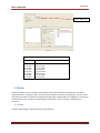
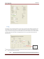
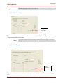
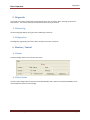
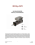
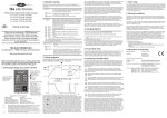
1
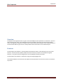
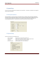
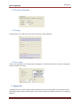
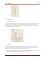
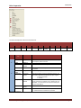
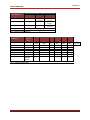
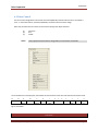
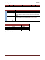
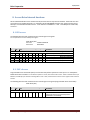
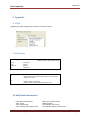
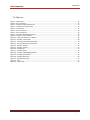
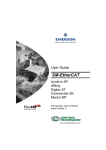
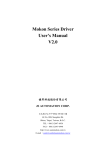
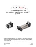
Tritex II
CANopen Startup
Exlar Corporation
03/05/2013
Overview
The purpose of this application note is to get a Tritex with CANopen system operational “on the bench”, without a
load connected to the motor. Some additional comments are added at the end to assist with tuning a loaded
motor. The application note goes on to explain a basic system layout recommended for Tritex. At the end there is a
section entitled “Where to go from here” which provides links to information on more advanced topics.
Features
The Exlar Expert drive software is a GUI developed to interoperate with the Tritex 485 interface by way of USB
interface. All of the functions (Motion profiles) of the drive and user parameters are available through this
interface. It may also be used to configure drive user and CANopen interface parameters.
The Exlar Expert drive software is required for tuning and configuring digital I/O.
This method establishes communication and uploads all of the parameters from the drive to the PC, and the drive
stays online
Tritex CANopen Getting Started, v0.9
Page 2
03/05/2013
Exlar Corporation
1. System Setup
System menu allows configuration and viewing of system parameters. Parameters are divided into two segments
Factory and user parameters.
1.1.Factory Parameters
Factory parameters are stored as a block in non-volatile memory. The block contains a CRC (Cyclic Redundancy
Checksum) word to guarantee data integrity. At power-up, the factory parameter block is validated and copied to
its runtime location in RAM where all parameters are available for both reading and writing through their
individual MODBUS identifiers. Factory parameter include, maximum limits and system options.
1.2.System Setup
System menu allows one time configuration of:
Power up options
Module Control
User limits
Reaction methods
Delay power-up, state machine sequence etc.
Which interface (CANopen, Modbus or Digital I/O) has control
High current warnings and in position window
Quick Stop 606Ah, Fault reaction 605Eh etc.
Tritex CANopen Getting Started, v0.9
Page 3
Exlar Corporation
03/05/2013
1.3.Factory Calibration
1.4.Tuning
This page allows user to adjust the tuning of the motor base on their application.
1.5.User units
The user unit page, allows user to change the units displayed, in the Tritex drive software. It does not change data
written and stored in the drive.
2. Digital I/O
The Digital I/O screen is used to assign the input and output functions and LED outputs to the hardware I/O lines;
eight discrete inputs and four discrete outputs. Refer to Expert software for additional information on configuring
Digital I/O.
Tritex CANopen Getting Started, v0.9
Page 4
Exlar Corporation
03/05/2013
3. Networks
3.1.RS485 Modbus
The Tritex uses an RS485 hardware connection with a Modbus RTU protocol. The RS485 Modbus page allows the
user to set the Tritex communication parameters to best connect with their communication. Therefore, an
adapter will be required to interface from the RS232 or USB port on the PC to the RS485 port on the actuator (see
Installation section for details on the RS485 port).
3.2.CANopen
Exlar have implemented a CANopen protocol based on the ‘Communication Profile’ (CiA DS 301) in the Tritex,
which supports both direct access to device parameters and time-critical process data communication. These
parameters are accusable through the CANopen interface and Drive software.
Tritex with CANopen incorporates DS402 motor profile with several additional options that enhances the system
use in a system. These additions add flexibilities to the overall system performance.
Tritex CANopen Getting Started, v0.9
Page 5
Exlar Corporation
03/05/2013
The Tritex support Variable PDO mapping this means the PDOs can only be mapped or re-mapped during Preoperational state. This can be accomplished through SDO’s or using Exlar Drive software. The PDO programming
sequence of PDOs is handled using our drive software.
3.2.1. CAN Open
The CAN Open allows a simple method of changing Drive ID and Baud rate. Note, changes do not take effect until
new power cycle.
3.2.2. CAN Parameters
3.2.3. PDOs Setup
The object linker (translation tables) offers a significant improvement by supporting fully automated
mapping/linking of PDOs in only a few steps. All available objects are sorted according to input and output data.
A unique COB-ID (unique with respect to the entire CANopen network, not just the node) must be assigned to each
PDO which will be used over the CAN network. It is recommended using the Predefined Connection Set where ever
possible. It is the system designer’s responsibility to ensure that all PDOs have a unique COB-ID. It is best to assign
the COB-IDs in a logical order, with the most important PDOs assigned to the lowest COB-IDs.
Tritex CANopen Getting Started, v0.9
Page 6
03/05/2013
Exlar Corporation
27Fh = 200h + 7Fh
PDOs Predefined Connection Set
COB-ID(s) hex
Slave nodes
180 + NodeID
200 + NodeID
280 + NodeID
300 + NodeID
380 + NodeID
400 + NodeID
480 + NodeID
500 + NodeID
1. Transmit PDO
1. Receive PDO
2. Transmit PDO
2. Receive PDO
3. Transmit PDO
3. Receive PDO
4. Transmit PDO
4. Receive PDO
4. Motion
The device profile for drives and motion control defines the functional behavior of controllers for servo drives,
frequency inverters and stepper motors. The specification includes a finite state automaton (FSA). The state of the
drive determines which commands are accepted and if high power is applied. States are changed by a control-word
received from the host-controller can be initiated by internal events. The current state is indicated by the
statusword.
4.1.Home
The Home Page configures and commands the Home operation.
Tritex CANopen Getting Started, v0.9
Page 7
03/05/2013
Exlar Corporation
4.2.Jog
The Jog Page is used to command jog mode on the Tritex. Once jog mode has been enabled, the jog inputs can be
used to produce motion on the actuator. The inputs that will be used as jog inputs are determined by the Jog (+)
or Jog (-) command. Once the jog inputs have been enabled, they will remain enabled, until user disable operation.
The motion profile have several option are configurable by the user, Fast, slow velocity and acceleration and
deceleration rates.
(1)
Save
Initialization
parameters
(1)
Saves the current displayed as new Initialization value (Fast Slow Velocity, Acceleration, Declaration and Current
limit ), when entering mode for the first time.
NOTE!
Typical motion profile commands and options could be set each time on power up from host or
Tritex CANopen Getting Started, v0.9
Page 8
03/05/2013
Exlar Corporation
set using a configuration file and stored to NVM once. Clicking Jog (+) or (-) changes will
automatically generated a enter mode request of Jog.
4.3.Profile Velocity
(1)
Save
Initialization
parameters
(1)
Save current displayed as new Initialization value (Acceleration, Deceleration, Current Limit and Target Velocity
), when entering mode for the first time.
NOTE!
Typical motion profile commands and options could be set each time on power up from host or
set using a configuration file and stored to NVM once
4.4.Profile Torque
(1)
Save
Initialization
parameters
(1)
Save current displayed as new Initialization value (Target Torque and Slope), when entering mode for the first
time.
Tritex CANopen Getting Started, v0.9
Page 9
03/05/2013
Exlar Corporation
NOTE!
Typical motion profile commands and options could be set each time on power up from host or
set using a configuration file and stored to NVM once
Tritex CANopen Getting Started, v0.9
Page 10
03/05/2013
Exlar Corporation
4.5.Profile Position
NOTE!
Typical motion profile commands and options could be set each time on power up from host or
set using a configuration file and stored to NVM once
Options
FAULT ON NACK
A rising edge of NEW_SETPOINT IMMEDIATE and SETPOINT_ACK active will normally generate a 'warning' and raise the
SETPOINT_NACK event. If the PP_OPTION_FAULT_ON_NACK is selected, a fault will be generated instead.
SMART CONTINUE
When a new SETPOINT is to be buffered (not immediately executed) and the PP_CONTROL_CONTINUOUS flag is set the default
action is to modify the END_VELOCITY of the previous (or active) set-point to its velocity so that it doesn't stop and targets the
new SETPOINT's velocity and distance when it completes. The PP_OPTION_SMART_CONTINUE overrides this behavior to set the
previous (or active) SETPOINT's END_VELOCITY to the lesser of the previous (or active) SETPOINT velocity and the new.
SETPOINT velocity.
INDEPENDENT DATA
Doesn't copy profile type, acceleration, and deceleration values from global profile data when loading a SETPOINT. The global
are copied into the SETPOINT setup structure only at startup.
RESET NSP
Internally resets CONTROL.NEW_SETPOINT as soon as the drive is able to accept another SETPOINT.
RESET NSP_ON TARGET
Internally resets CONTROL.NEW_SETPOINT when STATUS.TARGET_REACHED becomes active.
MAXIMUM BUFFERS
Maximum number of set-point buffers, maximum allows valve is 8; set-point buffer array is load only during mode
creation
Tritex CANopen Getting Started, v0.9
Page 11
Exlar Corporation
03/05/2013
5. Diagnostic
The overall system status is displayed on the diagnostic page; user can monitor faults, warnings, position and
temperatures. Also contain record of satirical information of history of the drive.
5.1.Status Log
The Status log page displays the log of Faults and Warning of the drive.
5.2.Diagnostics
The Diagnostic page displays the current Status and history of Faults of the drive.
6. Monitor / Control
6.1.Status
The Status wedge shows an overview the drive status.
6.2.Drive Status
The Drive Status wedge indictors show the statusword (6041.0h) states; while the controlword (6040.0h) can be
commanded from the Drive Control wedge.
Tritex CANopen Getting Started, v0.9
Page 12
03/05/2013
Exlar Corporation
The statusword provide the status of the PDS FSA.
15 -10
x…x
9
Remote
8
Homed
7
x
6
Setup
Drive Status
Statusword
5
4
Stop
DC Bus
Active
Ready
3
Fault
2
Enabled
1
Ready
0
Run
Figure 1 - Statusword
Bits
0
Drive control
bits
Exlar
Run
Description
1
2
Ready
Enabled
3
Fault
4
Voltage enable
5
DC Bus
Ready
Stop Active
6
Setup
Switch on
disabled
8
Homed
9
Remote
Manufacture
defined
Remote
DS402
Ready to run
Switch on
Operational
enabled
Fault active
Quick stop
actived
Drive is in normal runtime operation mode and is ready
to accept the power command
The drive is enabled and ready to command motion.
Fault has occurred in the system and fault reaction has
completed
Tritex voltage is greater than low voltage limits.
Indicates the PDS is reacting to deactivate request. The
final state is determined by Quick Stop option register.
0= Quick Stop Active
1= Inactive,
Drive is in SETUP mode and not ready for operation.
Some commands are available only in SETUP mode. The
SETUP bit is a 'convenience' event bit and is always the
inverse of the RUN bit
Drive is homed
0 = indicate that the controlword is not processed
1 = indicate that the controlword is processed
Figure 2 - Drive status bits
Tritex CANopen Getting Started, v0.9
Page 13
03/05/2013
Exlar Corporation
Profile position (pp)
13
oms
Following error
Profile velocity (pv)
x
Mode specific bits
12
oms
Set-point
acknowledge
x
Profile torque (pt)
x
x
Mode of Operation
Homing (hm)
Profile jog (pj)
10
tr
Final target
reached
Target velocity
reached
Target torque
reached
See Homing Mode
See Jog Mode
Figure 3 - Statusword, Mode specific bits
PDS 402 State
Not Ready to Switch On
Switch On Disabled
Ready to Switch On
Switch On
Operational Enabled
Quick Stop Active
Fault Reaction Active
Fault
Exlar
Internal
State
Not Ready
Setup
Run
Ready
Enabled
Stop Active
Fault
Reaction
Active
Fault
Bits in status word
3
2
fault
enable
6
setup
5
Stop active
1
ready
0
run
(sod)
(qs)
(f)
(oe)
(so)
(rtso)
0
1
0
0
0
0
0
X
X
1
1
1
0
X
0
X
0
0
0
0
1
0
0
0
0
1
1
1
0
0
0
1
1
1
1
0
0
1
1
1
1
1
0
X
1
0
0
0
DS 402: Bit
definition
Figure 4 – DS402 state machine states
Tritex CANopen Getting Started, v0.9
Page 14
03/05/2013
Exlar Corporation
6.3.Drive Control
The Drive control wedge button commands controlword (6040.0h) and LED indicators return controlword
state. In the similar fashion, statusword (6040.0h) is showed in the Drive Status wedge.
Basic steps in enable drive for manual control of drive through Exlar Expert Software:
(1)
(2)
(3)
NOTE!
Switch On
Run
Enable
Verify appropriate Drive Status is change base on ‘Drive Control ‘commands.
The controlword has a dual purpose, controlword the state machine of the drive and command the motion mode.
15
12
reserved
11
Break
release
10
reserved
9
Mode
specific
8
Halt
7
Fault
reset
MSB
6
5
4
Mode specific
3
Enable
2
Quick
Stop
1
Run
0
Switch
on
LSB
Figure 5 - Controlword
Drive Control bits
Controlword
Tritex CANopen Getting Started, v0.9
Page 15
03/05/2013
Exlar Corporation
15 -7
x…x
6
Reset fault
5
x
4
x
3
Enable
2
Stop
1
Run
0
Switch on
Figure 6 - Drive control bits
Bits
0
1
Drive Control
Switch on
Run
DS402
Switch on
Enable
voltage
2
Stop
Quick stop
3
Enable
6
Reset Faults
Enable
operation
Fault
reset
Description
interlock
The DS402 FSA 'ready to switch on' state is waiting for the drive to be set to enable high
level power. Since the drive doesn't control its own bus power, this state place for
controllers that require an extra command interlock before accepting the ENABLE bit.
Controllers that don't want the extra interlock may elect to force this control bit set at
start-up.
Command the drive to deactivate, base on Stop option To deactivate stop controlword
bit 2 must be equal to 1. Refer to Stop Action (0x605A.0) for more information
Commands drive into operational enable state.
Reset faults on the rising edge.
Figure 7 - Drive control bits
Mode of Operation
Profile position (pp)
Profile velocity (pv)
Profile torque (pt)
Homing (hm)
Profile jog (pj)
9
Change on
Set point
Reserved
Reserved
Operation mode specific bits
8
6
5
Halt
Abs/rel
Change set
Immediately
Halt
Reserved
Reserved
Halt
Reserved
Reserved
Halt
Halt
4
New set
Reserved
Reserved
Figure 8 - Controlword, Mode specific bits
Tritex CANopen Getting Started, v0.9
Page 16
03/05/2013
Exlar Corporation
7. Motion examples
This section contain sample configuration of the drive.
7.1.Homing
The Tritex drive support many aspects of the homing methods (1) described by DS 402. This includes the use of a
switch inputs and/or an encoder index pulse to determine the extent of travel, limit inputs, and a specific
acceleration, deceleration, normal speed and slow speed to use while homing. These homing inputs are
integrated into the Tritex and are user defined.
To configure the drive Inputs it is recommended using the Tritex Expert software. Below is an example of
configuring Home method 19.
Homing method 19
(1)
- POS_SW_ON_OFF
(Home on positive home switch (inactive)) (d)
Refer to Tritex CANopen manual for supported methods.
7.1.1. Configure Inputs
From the Digital I/O page configure the ‘Home Switch’ to your wired Input 5. (See Hardware interface manual for
information on connecting switch to Tritex.) For this example wire the ‘Home Switch’ to Input 5.
Figure 9 - Example - Home Switches
Tritex CANopen Getting Started, v0.9
Page 17
03/05/2013
Exlar Corporation
DS402 Description
Home Switch
Negative Limit Switch
Positive Limit Switch
Index Pulse
Source of Event
Configurable Input Event
Configurable Input Event
Configurable Input Event
Index Pulse
Figure 10 – Exlar Input Switches vs. DS402
7.1.2. Home drive
7.1.2.1. CANopen interface
Homing Mode – demonstrates home method 19 decimal using Service Data Objects (SDOs).
The below example sets typical motion profile commands a system would configure1, enabling the motor power2
and executing a homing function using SDOs with Node ID 65 (41h).
1
Typical configuring I/O should be set using Exlar Drive software and stored to NVM once. Motion user
parameters could be set each time on power up or configure and stored to NVM once.
2
Enabling the motor power only has to be done once on power up.
0641
0641
0641
00
00
00
2B
2B
2B
40
40
40
0641
0641
00
00
23
23
84
83
Typical motion profile commands and enabling sequence
Description
DSP402 state machine, 6040.0h
60 00 06 00 00
00 Send shutdown - transfer to Ready to Switch on
60 00 07 00 00
00 Switched on
60 00 0F
00 00
00 Operation Enable
Typical Motion Parameters
60 00 50 C3 00
00 Set deceleration to 3000 RMP/S, 6084.0h
60 00 50 C3 00
00 Set acceleration to 3000 RMP/S, 6083.0h
0641
00
2F
60
60
00
06
00
00
00
0641
0641
0641
0641
00
00
00
00
23
23
23
23
FF
7C
99
99
60
60
60
60
00
00
01
02
13
00
35
82
00
00
82
06
00
00
00
00
00
00
00
00
0641
00
2B
40
60
00
1F
00
00
00
0641
00
2B
40
60
00
0F
00
00
00
ID
RTR
Data
Set to Home Mode
Set to Profile Home Mode, 6060.0h
Set Homing Method, Offset and Speeds
Homing method 19 decimal
Homing Offset value = 0
Home Speed Fast 2000 RPM
Home Speed Slow 100 RPM
Start Homing
Start Homing and remove active Halt
Stop Homing after home is acquire
Stop Homing (This will Halt Homing and keep
Operational Enable)
Figure 11 - Example: Home mode
Tritex CANopen Getting Started, v0.9
Page 18
03/05/2013
Exlar Corporation
7.1.2.2. Define Home
To define current position as home using PAC commands, can be accomplish using Tritex Drive software or through
CANopen. By using accessing drive internal commands through CANopen interface.
ID
RTR
Typical motion profile commands and enabling sequence
Description
Data
0641
0641
0641
00
00
00
2B
2B
2B
40
40
40
60
60
60
00
00
00
06
07
0F
00
00
00
00
00
00
00
00
00
0641
00
2F
60
60
00
06
00
00
00
0641
00
23
09
21
00
00
00
20
37
DSP402 state machine, 6040.0h
Send shutdown - transfer to Ready to Switch on
Switched on
Operation Enable
Set to Home Mode
Set to Profile Home Mode, 6060.0h
Define Current Position as Zero
(2)
Write Pac System.Post.Commands.DefineHome
(924942336-> 0x37218000)
Figure 12 - Example: Home Absolute Position
(1)
(2)
Halt is enabled automatically, when a Motion mode becomes active.
Same function as “Define Home” within ‘Expert Tritex’ software
Figure 13 - Drive Software Home Commands
Tritex CANopen Getting Started, v0.9
Page 19
03/05/2013
Exlar Corporation
7.2.Position
Profile Position Mode – demonstrates the different move types supported for position control executed via Service
Data Objects (SDOs).
Exlar support relative and absolute moves to position. Using either relative or absolute moves, the user can also
select (by the control word data) if the target position should be reached before another target position is allowed
(finish first) or if the actuator should execute a newly received target position even if still in motion (immediate).
The below example sets typical motion profile commands a system would configure, enabling the motor power 2
and the four different move types2 supported in Profile Position Mode using SDOs with Node ID 65 (41h).
3000 RMP/S
2000 RPM
10.000 REVs
Acceleration:
3000 ÷ 0.06 = 5000 (0xC350)
Target Velocity: 2000 ÷ 0.06 = 3333 (0x8235)
Distance:
10000 ÷ 0.0001 = 100000 (0x0186A0)
1
Enabling the motor power only has to be done once on power up. Motion user parameters could be set each
time on power up or configure and stored to NVM once.
2
The Control Word data selects the move type.
0641
0641
0641
00
00
00
2B
2B
2B
40
40
40
0641
0641
0641
00
00
00
23
23
23
84
83
81
Typical motion profile commands and enabling sequence
Description
DSP402 state machine, 6040.0h
60 00 06 00 00
00 Send shutdown - transfer to Ready to Switch on
60 00 07 00 00
00 Switched on
60 00 0F
00 00
00 Operation Enable
Typical Motion Parameters
60 00 50 C3 00
00 Set deceleration to 3000 RMP/S, 6084.0h
60 00 50 C3 00
00 Set acceleration to 3000 RMP/S, 6083.0h
60 00 35 82 00
00 Set max user velocity to 2000 RPM , 6081.0h
0641
00
2F
60
60
00
01
00
00
00
0641
0641
0641
00
00
00
23
2B
2B
FF
40
40
60
60
60
00
00
00
A0
1F
0F
86
00
00
01
00
00
00
00
00
0641
0641
0641
00
00
00
23
2B
2B
FF
40
40
60
60
60
00
00
00
E0
3F
2F
93
00
00
04
00
00
00
00
00
0641
0641
0641
00
00
00
23
2B
2B
FF
40
40
60
60
60
00
00
00
50
5F
4F
C3
00
00
00
00
00
00
00
00
0641
0641
0641
00
00
00
23
2B
2B
FF
40
40
60
60
60
00
00
00
A0
7F
6F
86
00
00
01
00
00
00
00
00
ID
RTR
Data
Set to Profile Position Mode
Set to Profile Velocity Mode, 6060.0h
Move Absolute (finish first)
Set Target Position to 10.000 REVS
Set Control Word bit 4 to 1
Set Control Word bit 4 to 0
Move Absolute (immediate)
Set Target Position to 30.000 REVS
Set Control Word bit 4 to 1
Set Control Word bit 4 to 0
Move Relative (finish first)
Set Target Position to 50.000 REVS
Set Control Word bit 4 to 1
Set Control Word bit 4 to 0
Move Relative (immediate)
Set Target Position to 10.000 REVS
Set Control Word bit 4 to 1
Set Control Word bit 4 to 0
Figure 14 - Example: Position
Tritex CANopen Getting Started, v0.9
Page 20
03/05/2013
Exlar Corporation
7.3.Velocity
Exlar supports the ability to move in velocity mode. Once in Profile Velocity Mode, any new target velocity will be
executed immediately.
The below example sets typical motion profile commands a system would configure 1, enabling the motor power2
and sending a new target velocity using SDOs with Node ID 65 (41h).
3000 RMP/S
1000 RPM
Acceleration:
3000 ÷ 0.06 = 5000 (0xC350)
Target Velocity: 1000 ÷ 0.06 = 16667 (0x411A)
1
Typical motion profile commands could be set each time on power up from host or set using a configuration file
and stored to NVM once.
2
Enabling the motor power only has to be done once on power up.
ID
RTR
Typical motion profile commands and enabling sequence
Description
Data
0641
0641
0641
00
00
00
2B
2B
2B
40
40
40
60
60
60
00
00
00
06
07
0F
00
00
00
00
00
00
00
00
00
0641
0641
00
00
23
23
84
83
60
60
00
00
50
50
C3
C3
00
00
00
00
DSP402 state machine, 6040.0h
Send shutdown - transfer to Ready to Switch on
Switched on
Operation Enable
Typical Motion Parameters
Set deceleration to 3000 RMP/S, 6084.0h
Set acceleration to 3000 RMP/S, 6083.0h
0641
00
2F
60
00
03
00
00
00
Set to Profile Velocity Mode
Set to Profile Velocity Mode, 6060.0h
00
Motion Mode default condition are loaded
Send new Target Velocity
Target Velocity 1000 RPM, 60FF.0h
0641
00
23
60
FF
60
00
1A
41
00
Figure 15 - Example: Velocity
(3)
Halt is enabled automatically, when a Motion mode becomes active.
Tritex CANopen Getting Started, v0.9
Page 21
03/05/2013
Exlar Corporation
7.4.Jog
Exlar supports the ability to move in Jog mode. The below example sets typical motion profile commands a system
would configure1, enabling the motor power2 and sending a new target velocity using SDOs with Node ID 65 (41h).
100 RMP,
5000 RPM/S,
5000 RMP/S,
NOTE!
Slow Velocity:
Acceleration:
Deceleration:
100 ÷ 0.06 = 1666 (0x682)
5000 ÷ 0.06 = 8333 (0x14585)
5000 ÷ 0.06 = 8333 (0x14585)
CANopen supports Jog directly with the following functions:
Jog Slow - Positive when active
1
Typical motion profile commands could be set each time on power up from host or set using a configuration file
and stored to NVM once.
2
Enabling the motor power only has to be done once on power up.
ID
RTR
Typical motion profile commands
Description
Data
0641
0641
0641
00
00
00
2B
2B
2B
40
40
40
60
60
60
00
00
00
06
07
0F
00
00
00
00
00
00
00
00
00
0641
0641
0641
0641
00
00
00
00
23
23
23
23
0B
0C
0D
60
36
36
36
60
00
00
00
00
86
85
85
FE
02
45
45
00
00
01
01
00
00
00
00
00
0641
00
2B
60
00
8F
00
00
00
40
DSP402 state machine, 6040.0h
Send shutdown - transfer to Ready to Switch on
Switched on
Operation Enable
Typical Motion Parameters
Set Slow Velocity 100 RMP
Set Acceleration 5000 RPM/S
Set Deceleration 5000 RPM/S
Jog Mode (-2)
Jog Function
Halt Jog
Figure 16 - Example Jog
Tritex CANopen Getting Started, v0.9
Page 22
03/05/2013
Exlar Corporation
7.5.Torque
If a torque that is relative to current of 2 amps is needed, and object 0x6075 (Motor Rate Current “Continuous
Current”) is 3200 mA, then:
Target Torque:
Slope:
[6071.0] = 2000 mA x 1000 / 3200 mA = 625 ( 271h)
[6087.0] = 180.0 % / sec
This number means 62.5 % of Motor Rate Current
ID
RTR
Typical motion profile commands and enabling sequence
Description
Data
0641
0641
0641
00
00
00
2B
2B
2B
40
40
40
60
60
60
00
00
00
06
07
0F
00
00
00
00
00
00
00
00
00
0641
00
2B
87
60
00
50
46
00
00
0641
00
2F
60
60
00
04
00
00
00
0641
00
2B
40
60
00
0F
00
00
00
0641
00
2B
71
60
00
71
02
00
00
DSP402 state machine, 6040.0h
Send shutdown - transfer to Ready to Switch on
Switched on
Operation Enable
Typical Motion Parameters
Set slope 180.0 %/sec, 6087.0h
Set to Profile Velocity Mode
Set to Profile Torque Mode, 6060.0h
Disable Motion Halt
(3)
Clear Halt
Send new Target Torque
Target Torque 62.5 % 6071.0h
Figure 17 - Example Torque
(3)
Halt is enabled automatically, when a Motion mode becomes active.
Tritex CANopen Getting Started, v0.9
Page 23
03/05/2013
Exlar Corporation
7.6.PDO Mapping
The following is an example of mapping PDO for position Profile:
Device ID = 127 (7Fh)
RPDO -1, COB-ID = 27Fh
(Controlword-6040h, Target Position-607Ah)
TPDO -1, COB-ID = 1FFh
Transmit on Change
(Statusword-6041h)
ID
RTR
Typical motion profile commands and enabling sequence
Description
Data
Typical Motion Parameters
067F
067F
067F
00
00
00
23
23
23
84
83
81
60
60
60
00
00
00
50
50
35
C3
C3
82
00
00
00
00
00
00
067F
067F
067F
067F
067F
067F
067F
00
00
00
00
00
00
00
23
2F
23
23
2F
2F
23
00
00
00
00
00
00
00
14
16
16
16
16
16
14
01
00
01
02
02
00
01
7F
00
10
20
FF
02
7F
02
00
00
00
00
00
02
00
00
40
7A
00
00
00
80
00
60
60
00
00
00
067F
067F
067F
067F
067F
067F
00
00
00
00
00
00
23
2F
23
2F
2F
23
00
00
00
00
00
00
18
1A
1A
18
1A
18
01
00
00
02
00
00
FF
00
10
FF
01
FF
01
00
00
00
00
01
00
00
41
00
00
00
80
00
60
00
00
00
067F
00
2F
40
60
00
06
00
00
00
000
01
00
01FF
027F
01FF
027F
01FF
027F
01FF
70
06
31
07
33
0F
23
02
00
02
00
02
00
06
00
00
00
00
00
00
00
00
00
00
00
00
027F
027F
01FF
027F
01FF
01FF
0F
1F
12
0F
02
06
00
00
B7
00
B7
B7
E0
E0
93
93
04
04
00
00
E0
93
04
00
Set deceleration to 3000 RMP/S, 6084.0h
Set acceleration to 3000 RMP/S, 6083.0h
Set max user velocity to 2000 RPM , 6081.0h
Configure RPDO-1
Disable RPDO-1 COB-ID
Write zero to entries
Configure Map1 with 6040.0 -Controlword
Configure Map2 with 607A.0 -Target Position
Configure Transmission Type
Write 2 to Entry count
Enable RPDO-1 COB-ID
Configure TPDO-1
Disable TPDO-1 COB-ID
Write zero to entries
Configure Map1 with 6041.0 ,Statusword
Configure 1600.5, Transmit on Change
Write 1 to Entry count
Enable TPDO-1 COB-ID
Mode of Operation - Position
Write 6 to Mode of Operation
Enable NMT Operation Mode
Operational Mode
DSP402 state machine
<--- Current Status (Switch on Disabled)
---> (Shutdown - )
<--- Drive sends TPDO1- (Ready to Switch on)
---> (Switched on)
<--- Drive send TPDO1 – (Switch on)
---> (Operation Enable)
<--- Drive sends TPDO1 – response (Enable)
Command Position
---> Set Target Position to 30.000 REVS
---> Set Control Word bit 4 to 1 (New Set Point)
<--- Drive sends TPDO1 – response
---> Set Control Word bit 4 to 0
<--- Drive sends TPDO1 – (Set Point ACK)
<--- Drive sends TPDO1 – (In Position)
Figure 18 – Example: PDO Mapping Position
Tritex CANopen Getting Started, v0.9
Page 24
03/05/2013
Exlar Corporation
8. Access Drive Internal functions
GID or Global Identification is the method used by the Tritex drive to map internal variables. These GID’s are then
cross reference to installed protocols. For example a GID of 0x3C000000 represents the System warnings and is
identify as “SYSTEM.MOTION.EVENTS.FAULTS” cross reference to Modbus ID “ 1900 “ and CANopen ID “Index 3384,
subindex 0“.
8.1.GID access
The following demonstrates method to access internal registers using GID.
For example read and write to CANopen ID register:
Node ID 65 (41h)
GID name:
GID address:
ID
RTR
CANOPEN.PARAM.ID
0x82200000
Reading / writing Drive GID sequence
Description
Data
0641
0641
00
00
23
40
02
02
20
20
01
02
00
00
00
00
20
00
82
00
0641
0641
00
00
23
2B
03
03
20
20
01
02
00
01
00
00
20
00
82
00
Reading Drive Parameter
Write GID to System Read, Object 2002.1
Read Data, Object 2002.2
Write Drive Parameter
Write GID to System Write , Object 2003.1
Write Data: ID = 1, 2 bytes, Object 2003.2
Figure 19 - Example System Read
8.2. PAC’s Access
Programmable Access Commands (PAC’s) are functions that perform operations in the system. For example the
below PAC function will define current absolute position as home, while home mode is active. Refer to Interface section (UI
Modbus, and CANopen) for methods of sending PACs to drive. Note, if interface does not have control rights command will not
execute.
The following demonstrates method to access internal registers using PAC (Programmable Access Commands).
Node ID 65 (41h)
ID
0641
RTR
00
Writing PAC sequence
Description
Data
23
09
21
00
00
00
20
37
Write PAC
Write Pac
CommandSystem.Post.Commands.DefineZero
(924844032-> 0x3720.0000)
Figure 20 - Example PAC Access
Tritex CANopen Getting Started, v0.9
Page 25
03/05/2013
Exlar Corporation
8.3.User Units example
CANopen associates a scale factory to a group of registers, for example scale factory 1 is always assigned to
Position measurements. This conversion is transparent to CANopen interface.
Name
Scale Factor 1 – Numerator
Scale Factor 1 – Denominator
Scale Factor 2 – Numerator
Scale Factor 2 – Denominator
Scale Factor 3 – Numerator
Scale Factor 3 – Denominator
Units
UINT32
UINT32
UINT32
UINT32
UINT32
UINT32
Att
RW
RW
RW
RW
RW
RW
Description
Position
Velocity
Acceleration
GID
CANOPEN.PARAM.CONVERT.0.MULTIPLIER
CANOPEN.PARAM.CONVERT.0.DIVISOR
CANOPEN.PARAM.CONVERT.1.MULTIPLIER
CANOPEN.PARAM.CONVERT.1.DIVISOR
CANOPEN.PARAM.CONVERT.2.MULTIPLIER
CANOPEN.PARAM.CONVERT.2.DIVISOR
Modbus
7560
7562
7564
7566
7568
7570
CO
2102.1
2102.2
2103.1
2103.2
2104.1
2104.2
Figure 21 – User Units CANopen
Internal units= (user value) * (Numerator1 / Denominator1)
User value = (internal units) * (Denominator1 / Numerator1)
NOTE!
Write operation
Read operation
Default Numerator and Denominator are 1
The following example demonstrates reading/ writing using ‘User Units’ for Target Position (607A.h):
Scale Factor 1 – Numerator:
Scale Factor 1 – Denominator:
Internal units:
1
2
0.0001 Rev
Write
Target Position
Internal Units
2000
= 2000 * 1/2
Target Position
= 1000 * (2 /1)
Read
NOTE!
Thirty-two bit conversion is used and rounding error could occur between read and
write values.
Tritex CANopen Getting Started, v0.9
Page 26
03/05/2013
Exlar Corporation
9. Appendix
9.1.Tips
Highlighting and right clicking display variable ID and help information.
Figure 22 - Expert Software Tips
9.2.Notations
0.001 rated
mrps/s
mrps
0.0001 rev
ms
Percentage of Rated (GID=SYSTEM.BUS.FACTORYPARAM.IRATED)
(CANopen -6075.0, Motor Rated Current)
Acceleration
Velocity
Distance
milliseconds
Figure 23 - Units
(b)
When read/write from Modbus data length is word, while from
CANopen it is a byte.
(M)
CANopen Object is mappable
CANopen Profile –Motion DS402 specification name
(d)
Figure 24 – Superscript
10. Additional information
Expert Software Manual.pdf
Tritex_CO.eds
Tritex CANopen.pdf
Tritex CANopen Getting Started.pdf
Tritex CANopen Getting Started, v0.9
Expert Drive software manual
CANopen EDS file
Tritex CANopen user manual
Tritex CANopen Getting started manual
Page 27
Exlar Corporation
Tritex CANopen Getting Started, v0.9
03/05/2013
Page 28
Exlar Corporation
03/05/2013
11. Figures
Figure 1 - Statusword.............................................................................................................................................. 13
Figure 2 - Drive status bits ...................................................................................................................................... 13
Figure 3 - Statusword, Mode specific bits ............................................................................................................... 14
Figure 4 – DS402 state machine states ................................................................................................................... 14
Figure 5 - Controlword ............................................................................................................................................ 15
Figure 6 - Drive control bits .................................................................................................................................... 16
Figure 7 - Drive control bits .................................................................................................................................... 16
Figure 8 - Controlword, Mode specific bits ............................................................................................................. 16
Figure 9 - Example - Home Switches ....................................................................................................................... 17
Figure 10 – Exlar Input Switches vs. DS402 ............................................................................................................. 18
Figure 11 - Example: Home mode .......................................................................................................................... 18
Figure 12 - Example: Home Absolute Position ........................................................................................................ 19
Figure 13 - Drive Software Home Commands ......................................................................................................... 19
Figure 14 - Example: Position .................................................................................................................................. 20
Figure 15 - Example: Velocity .................................................................................................................................. 21
Figure 16 - Example Jog .......................................................................................................................................... 22
Figure 17 - Example Torque .................................................................................................................................... 23
Figure 18 – Example: PDO Mapping Position .......................................................................................................... 24
Figure 19 - Example System Read ........................................................................................................................... 25
Figure 20 - Example PAC Access .............................................................................................................................. 25
Figure 21 - Expert Software Tips ............................................................................................................................. 27
Figure 22 - Units ..................................................................................................................................................... 27
Figure 23 – Superscript ........................................................................................................................................... 27
Tritex CANopen Getting Started, v0.9
Page 29