1
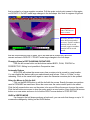
B-PLATES User Manual B-PLATES V3.0 Copyright 1995 Vacanti Yacht Design Installing the PROGRAM Run the Installation program found on the CD ROM and follow on screen directions. SPECIAL NOTES: B-PLATES does not have the ability to look for files in any directory besides its own. Therefore you must either store the desired PROLINES file in the B-PLATES directory when using PROLINES or copy the PROLINES file into the B-PLATES directory manually. PROLINES 6, 98, 7 for Windows Users: B-PLATES CANNOT read PROLINES 6,7 or PROLINES 98 data files. Please save any file that will be used in B-PLATES as a PROLINES 5 data file. This is accomplished by choosing: File, Save As… in PROLINES 6,7 or 98. Then select the File Type Pull Down at the bottom of the Dialog box. Choose the PROLINES 5/6 File type. Select PROLINES 5 when asked in the popup window. Using B-PLATES Note: Click means press the left mouse button once, quickly and release it. SELECT means press the left mouse button down and drag a highlight bar over the menu item. Then release the left mouse button to choose that item. 1) Select the FILE Menu 2) Select READ .PHL FILES (PROLINES files end with the extension .phl) 3) Select a hull file from the list of files by clicking on the file name ERROR 205, 207 – If these errors occur immediately after selecting a hull file name, it is caused by problems in the PROLINES Hull File. Usually there are two reasons for this error 1) You have left a chine break at the transom of the hull 2) You have caused a “fold” in the hull by overlapping vertex control points. Read the section below on hull development problems. 4) Accept the default names for session and plate names. 5) Select the CHECKLISTS Menu 6) Select the PLATE DEVELOPMENT ENSEMBLE. This choice allows you to determine which areas of the hull that B-PLATES will actually develop into plates. This choice provides considerable flexibility in using B-PLATES. It has its greatest value in allowing you to develop each plate on the hull in the most effective manner. For example, BPLATES can generate ruling lines that start at the top of each plate, at the bottom of each plate or alternately between the top and the bottom of each plate. This is significant, in that it actually corresponds to bending the plate onto the hull in 3 different ways. The plate may not be developable for all ruling directions. Choosing a different ruling direction for each plate allows the most effective plate development. Having the ability to determine which plates are developed at any time from the checklist provides two functions. The first is it allows changing the ruling line direction of each plate by simply selecting only the plate or plates that you wish to develop with a given ruling direction. Secondly, once you have developed a plate properly, remove it from the checklist so that it will not be affected by further changes in ruling direction. Initially, select all of the plates from the checklist by clicking on the letters ND (Not Developed) in each plate. Each letter set will be highlighted in color to show that that it has been selected. To exit this menu, click on the word EXIT. 6) Select the PLATES menu. 7) Select the DEVELOP PLATES menu item. B-PLATES will show a perspective view of the hull and will show the plates being developed by drawing ruling lines. WHICH PLATES GO WHERE ON THE HULL? B-PLATES plots the developed plates exactly in the order that they would appear on the hull if viewed in profile. In other words, the bottom plate on the screen is the bottom plate on the hull. The top plate on the screen is the plate along the sheer of the hull. The plates are NUMBERED from bottom to top. Plate Number 1 is the lowest or bottom plate. The highest numbered plate is the sheer plate. ARE THE PLATES CORRECTLY DEVELOPED? B-PLATES will draw ruling lines of correctly developed plates in violet and yellow. Green lines that lie 90 degrees to the ruling lines cross plate areas that do not develop properly. Plates that develop properly will have a realistic outline shape that is defined by a smooth curve. Plates that generate very jagged outlines and have a very warped or twisted look are not properly developed. PLATE DEVELOPMENT CHOICES When plates are developed for the first time in B-PLATES, the ruling lines are generated by alternately ruling from the top plate edge and the bottom plate edge. This may develop some plates correctly and others incorrectly. There are three steps to develop plates that did not develop with the default ALTERNATING ruling lines (Top and Bottom). 1) Take note of which plates have developed properly. Count from the bottom of the screen as plate 1 and increase to the top of the screen. From the CHECKLIST menu, choose the PLATE DEVELOPMENT ENSEMBLE item. This is a list of plates that you want B-PLATES to develop. Any plate that has developed properly can be removed from this list and it will remain in memory, but will not be affected by further plate development. A plate is selected for development when the letters ND (Not Developed) or DEV (Developed) are highlighted in blue. Click on the letters ND or DEV to cause that plate to be selected (Highlighted) or unselected (Not highlighted). Using your notes, choose to leave only those plates that still need to be developed properly on the checklist. Remove the highlight from the plates that are developed correctly. Click on the word EXIT to leave this menu. 2) Select the DEFAULTS menu. From the list select the OPERATIONAL item. From the pop-up list, click on the ruling lines entry once. It will change from ALTERNATE to TOP or BOTTOM. Clicking on the button several times will cause the button name to change among the choices of Alternate, Top or Bottom. If the first try to develop plates was set at “alternate” then choose either “top” or “bottom”. Click on QUIT to escape the menu. 3) Select the PLATES menu and select DEVELOP PLATES. B-PLATES will develop only those plates remaining on the checklist with the new ruling line direction. If the plates still do not develop properly, try the last ruling line direction setting as described in step 2 above. Select DEVELOP PLATES again from the PLATES menu if the ruling line direction is changed. ALL RULING LINE DIRECTIONS TRIED BUT THE PLATES DID NOT DEVELOP PROPERLY NOW WHAT DO I DO? The most common error: B-PLATES may fail to develop plates or even crash with a run time error 207 (math error) if you have done the following. If you have collected multiple vertices (2 or more) together by hand using the mouse or keys when designing your hull in PROLINES, you may have created a small fold in the hull without realizing it. For example, the design may have the ends of two chines brought together at the bow. On screen the hull may look fine, but vertex 3 may actually lie above vertex 4 by just 1 mm. This creates a tight fold in the plate, and even as small as this is, BPLATES will see this folded section, and will have problems developing the two plates. If you created chines by laying multiple vertices on top of each other using the mouse or keys, this folded hull error will also occur. There are two solutions in PROLINES. 1) Use the spreadsheet editor in PROLINES to look at the numerical values of the vertices. Force the common vertex locations to be EXACTLY the same. 2) Consider using the CREATE A CHINE BREAK function in PROLINES. Finally, consider setting the station tension to 1 (SPLINE TENSION in SPLINE MENU) if your hull is made of flat plates only. Save your corrections within PROLINES and return to B-PLATES. FAIRING THE HULL B-PLATES has excellent editing tools and a hull fairness indicator built in. If for whatever reason some plates will not develop at any of the three ruling line settings, you can edit the hull in BPLATES using the mouse. (Keyboard editing is in development) Select EDIT GAUSSIAN CURVATURE from the FAIRNESS menu. A special screen will pop up that allows selecting any view of the hull along with powerful editing tools. The standard vertex control points found in PROLINES will also be drawn. The hull will be rendered in colors that corresponds to the curvature of the hull in that area. Your task is to select the view that will give you the best change to see the unfairness that prevents B-PLATES from correctly developing the plates. Look at the hull in the region that did not develop correctly. Look for a rapid change in curvature from positive to negative and back again. Regions of the hull that have bright green colors surrounded by light red indicates a region that is pushed in or has a negative curvature. Pull the vertex control point nearest to this region out SLIGHTLY. Do NOT make large changes in the hull shape. Also look for regions of light red Vertex control point. Click here to move a vertex. Curvature indicator. Colors on the hull correspond to curvature. Positive numbers mean the hull is curved outward, negative numbers mean the hull is curved inward. that are surrounded by blue or green, this is an area that is pushed out. Move the nearest vertices in SLIGHTLY. DO NOT make large changes in the hull shape. Changing Views in EDIT GAUSSIAN CURVATURE: Click the left mouse button on the buttons marked BODY, PLAN, PROFILE or PERSPECTIVE. Editing is not possible in Perspective view. Automatic Redraw B-PLATES will redraw the screen every time a vertex point is moved to a new location. You can disable this feature while you make several small moves. Click on “A Rdrw” to stop redrawing. Click on the same button again to cause the Gaussian curvature plot to be updated. Using the Mouse to Fair the Hull Click on the MOUSE button to edit the hull with the mouse. Exactly the same conventions used in PROLINES are used here. Move the cursor over the vertex control point to be edited. Click the left mouse button once on the vertex to be moved. Move the mouse to move the vertex. Click the left button once more to drop the vertex point in a new location. Now click the left mouse button on a new vertex and move it or click the RIGHT mouse button to STOP EDITING. UNDO a VERTEX MOVE If a change in the hull shape produces a bad result, you can undo that change or up to 10 consecutive changes by clicking on the UNDO button. Hiding / Showing the Vertex Net If viewing the vertex net causes some confusion you can cause it to be hidden from view and then redisplayed later. Click on the REMOVE NET button. Later when you wish to redisplay the net the button will be labeled DRAW NET. Click the button to show the net once more. Hiding the net makes it easy to see the edges of the plates, which are drawn on the hull in black. EXIT the Gaussian Curvature Editing Screen When editing has been completed, click on the EXIT button. Any changes to the hull that have been made are in memory but have not yet been saved in a standard PROLINES .PHL file. Choose the SAVE FILE function in the FILE menu. (Not available in DEMO). DEVELOPING PLATES AFTER FAIRING Having faired the hull, it is time to try to develop plates once more. Choose DEVELOP PLATES from the PLATES menu. The plates last checked for development in the PLATE DEVELOPMENT ENSEMBLE will be developed using the ruling direction chosen last. If the newly faired plate is improved but still shows regions not developed properly, then change the ruling direction to one of the remaining two directions. The ruling direction is changed in the DEFAULTS menu, in the OPERATIONAL menu item. If necessary, repeat the fairing steps outlined above. There is no limit to how many times the design and fairing cycle are used. Viewing the Developed Plates Once the plates have been developed, all of the plates can be viewed as flat sections in the VIEWS menu. However, only those plates that have been selected for DISPLAY in the PLATE DISPLAY ENSEMBLE (CHECKLIST menu) will be drawn. It is possible to inspect the plates in great detail in this view by using the ZOOM function found in the VIEWS menu. Choose from the numbered list of plates (1 is the bottom plate near the keel / fairbody) the plate to be displayed in ZOOM mode. Click the left mouse button once at one corner of a window then drag the mouse (release the mouse button) and click the RIGHT mouse button to close the window. The region enclosed by the window will be drawn in detail. To exit the ZOOM function click once in the lower screen region and click once again outside the plate selection list. Choose any other view or function in B-PLATES to erase the zoomed screen that remains. OUTPUT PLATES The plates that will be exported to a 2-D (X and y only) DXF file are those selected in the DXF OUTPUT ENSEMBLE. Choose these plates from the CHECKLIST MENU. This option allows the export of all of the plates in a single file or the export of a single plate in a file. The files exported can contain the outer boundary, the ruling lines and station markers that can correspond to the location of frames. Choose the station spacing by selecting the STATION menu item from the DEFAULTS menu. DXF files are not available in the demo version of B-PLATES. PLATE NESTING and CNC Cutting There are excellent 3rd party programs available for the tasks of plate nesting and Computer Numerically Controlled cutting. Once you have exported a DXF file of the hull plates to a program like AutoCAD, CADKEY, Microstation or other major CAD program, it will be possible to nest plates and generate CNC code to create them automatically. Contact your CAD dealer for programs and cost. TESTING THE PLATES Before committing to full-scale construction of the plates, consider building a scale model of the hull by plotting or printing the plates on paper. Glue the paper to a stiff material such as plywood veneer or modeling board. Cut out the plates with appropriate tools. The smoother and more accurately the cut is made to follow the plate outline, the more likely the model will show excellent results.