1
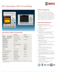
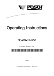
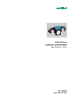
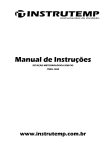
Hardware
User’s Manual
Comat AG Bernstrasse 4 CH-3076 Worb
www.comat.ch
[email protected]
Tel. +41 (0)31 838 55 77
Fax +41 (0)31 838 55 99
BaHw BoxX / 1.2004 E
Preface
Preface
Thank you for purchasing the Comat BoxX series intelligent controller from our company.
Whilst you may have a good knowledge and understanding of these products you are re-quested to
take some time to read this manual before operation. This will allow you to utilise the more
advantageous benefits of the product.
The Comat BoxX series intelligent controller uses function blocks for programming and a liquid
crystal display is provided for manual programming.
In the past the control function of a PLC required large sections of program and instruction sets
whereas the Comat BoxX series uses function blocks. When several function blocks are linked
together in a specific way then relatively complicated control functions can be implemented so that the
programming can be simplified.
The Comat BoxX series intelligent controller can be used very extensively for automation of
mechanical equipment, flow control, building management systems and many other fields.
This manual will describe in detail the functional characteristics and operating method of the Comat
BoxX series controller.
Note:
(1)
Copyright of this manual and patent of the device are the property of Comat AG.
No reproduction or duplication of all or part of the contents of this manual is permitted
without prior consent.
(2)
Our company reserves the right to make changes in design for improvement without
notification.
(3)
In the event that something is missing or there are discrepancies in this manual then please
contact us and we will endeavour to incorporate your comments in the next revision.
This issue replaces all previous issues.
Availability, errors and specifications subject to change without notice.
2
Comat BoxX, Hardware User’s Manual / 1.2004 E
Safety guide
Safety guide
This manual contains the precautions necessary to ensure your personal safety ands for the protection
of the product and the connected equipment. These precautions are highlighted with a triangle
“WARNING” symbol in this manual and are marked according to the danger levels as follows:
Danger:
This indicates that if appropriate precautions are not taken, serious incidents of personal
injuries or death or loss/damage to property may occur.
Caution:
This indicates that if appropriate precaution are not taken then injuries or losses of
properties will take place
Warning:
Only qualified personnel are allowed to debug and operate this equipment. The qualified
personnel are those who carry out commissioning, grounding according to the current
safety practices and standards.
Note:
Reminds you to pay particular attentions to the important information related to the products,
disposal of products or the specific part of documents.
Only when this product is transported, stored , and installed in a proper way and operated
and maintained according to the recommendations, can it implement the functions and
properly reliably.
Note:
1. It is prohibited to plug in or pull out the AF-C232 and LCD board when Comat BoxX machine is
powered.
2. The default of Comat BoxX password is 0001.
3. The default of Comat BoxX address is 000.
4. The outputs of the function blocks can not be connected together.
Comat BoxX, Hardware User’s Manual / 1.2004 E
3
Table of contents
Table of contents
CHAPTER I ................................................................................................................ 5
Brief introduction to Comat BoxX....................................................................................................... 5
1.1 Structure of Comat BoxX............................................................................................................. 5
1.2 Specifications and models ............................................................................................................ 7
1.3 Features of Comat BoxX .............................................................................................................. 8
CHAPTER II ..............................................................................................................10
Installation and wiring of Comat BoxX ............................................................................................ 10
2.1 Installation .................................................................................................................................. 10
2.1.1 Installation method .............................................................................................................. 10
2.1.2 Dimensions.......................................................................................................................... 11
2.2 Wiring of Comat BoxX .............................................................................................................. 12
2.2.1 Connection of power supply................................................................................................ 12
2.2.2 Connecting Comat BoxX input ........................................................................................... 13
2.2.3 Connecting of Comat BoxX output..................................................................................... 15
CHAPTER III .............................................................................................................16
Technical data...................................................................................................................................... 16
3.1 General data................................................................................................................................ 16
3.1.1 Ambient conditions ............................................................................................................. 16
3.1.2 Mechanical data................................................................................................................... 17
3.2 Electrical data ............................................................................................................................. 18
3.2.1 Electromagnetic compatibility ............................................................................................ 18
3.2.2 Power supply ....................................................................................................................... 18
3.3 Inputs.......................................................................................................................................... 19
3.3.1 Digital inputs ....................................................................................................................... 19
3.3.2 Analog inputs ...................................................................................................................... 19
3.4 Outputs ....................................................................................................................................... 20
3.4.1 Relay outputs....................................................................................................................... 20
3.4.2 Transistor outputs ................................................................................................................ 20
3.5 Voice unit AF-MUL................................................................................................................... 21
CHAPTER IV.............................................................................................................22
Operations of the keys on the LCD display....................................................................................... 22
4.1 Display of Comat BoxX status ................................................................................................... 23
4.2 Confirm password ...................................................................................................................... 23
4.3 Function...................................................................................................................................... 24
4.4 Set password, date and time ....................................................................................................... 25
4
Comat BoxX, Hardware User’s Manual / 1.2004 E
Chapter 1
Brief introduction to Comat BoxX
Chapter I
Brief introduction to Comat BoxX
1.1 Structure of Comat BoxX
The Comat BoxX intelligent controller is a new type of programmable controller. As it is programmed
by means of function blocks. It is simpler and easier to learn the programming of Comat BoxX than
conventional PLC programming (ladder diagram and instruction).
In the design concept of the products of the Comat BoxX series, the PLC is combined with a writer
where the program can be written directly with the functions keys on the LCD front panel. The
product is very compact and lightweight despite the many functions including local and remote
communication networking and monitoring.
Also there are telephone control, voice prompting and automatic dial functions by adding the
AF-MUL voice block.
At present the Comat BoxX is widely used in various industries in the agricultural and the home
automation market and can be used almost anywhere.
Comat BoxX, Hardware User’s Manual / 1.2004 E
5
Chapter 1
Brief introduction to Comat BoxX
1. Input of AC power
2. Input terminal
3. Communication interface
4. Operating keys
5. Output terminal (Output of relays or electronic transistor)
6. LCD display panel
Fig. 1.1
6
Comat BoxX, Hardware User’s Manual / 1.2004 E
Fig. 1.2
Chapter 1
Brief introduction to Comat BoxX
1.2 Specifications and models
Type
Power
Input
Output
AF-10MR-A
110-230VAC
6AC
4 relay
AF-10MR-D
24VDC
6DC or analog inputs
4 relay
AF-10MT-GD
24VDC
6DC or analog inputs
4 transistor- PNP
AF-20MR-A
110-230VAC
12AC
8 relay
AF-20MR-D
24VDC
12DC or analog inputs
8 relay
AF-20MT-GD
24VDC
12DC or analog inputs
8 transistor-PNP
AF-MUL
110-230VAC
Voice and Remote Unit
AF-MUL
12-24VDC
Voice and Remote Unit
AF-LCD
Removable panel for programming with LCD display
AF-CAP
Comat BoxX cover
AF-M232
Interface between Comat BoxX and Modem
AF-C232
Interface between Comat BoxX and PC modem
AF-BC
Bridge connector between Comat BoxX and AF-MUL
Quick II
Comat BoxX programming software
AF-Copy
Copy module
AF-USB
Interface cable
AF-AUD
Audio cable for AF-MUL
AF-ATL
WAV cable for AF-MUL
Comat BoxX, Hardware User’s Manual / 1.2004 E
7
Chapter 1
Brief introduction to Comat BoxX
1.3 Features of Comat BoxX
1. Removable programming panel with Liquid Crystal Display
There is an operating panel with LCD display on the front of the Comat BoxX (see note below).
The program can be edited with the operating keys on the LCD panel.
This panel can be removed for security purposes and be replaced with a cover (CAP).
Note:
The LCD panel can be plugged in or removed only after the power has been turned off.
2. Exquisite and compact design
Comat BoxX is an excellent choice to control your systems. Its performance and compact design,
offers you great opportunities of economical control solutions.
Type AF-10….: 90 x 71 x 58mm
Type AF-20….: 90 x 126 x 58mm
3. Large storage capacity
Control functions of Comat BoxX can be implemented with simple function blocks available in a
library.
The 20 pre-defined functions make programming easy and fast. The linking of function blocks
allows relatively complex control programs. A Comat BoxX has up to 127 function blocks for
program storage. A downloaded program into the EPROM can not be lost and does not require
battery backup.
4. Quick II programming software
QUICK II is a free-of-charge programming software
By using QUICK II, the program can be edited directly on the LCD panel or on a PC. The
program is loaded and written into the memory of Comat BoxX. QUICK II is a very friendly manmachine programming interface. It cannot only edit the function diagrams, but it also can run and
analyse the written program. It provides an off-line testing function to the user to avoid
inconveniences for on-line testing. QUICK II will not only guide you to implement or edit the
control programs, but also performs real-time monitoring for field environment and operation
conditions of Comat BoxX.
5. Real-time clock function
Comat BoxX intelligent controllers have an instant real-time clock function, and can execute
timed operations according to various schedules. You can set as many as up to 127 different time
intervals which makes the Comat BoxX most suitable for systems which require time control.
6. Digital and Analogue inputs
In addition to receiving switching inputs (Digital), Comat BoxX can also process analogue inputs.
This allows to monitor and control temperature, humidity, pressure, flow, level, etc., The values
can be transmitted to a remote to PC for data supervision.
7. Remote programming, supervision and control of data through a MODEM.
To implement programming, write and modify programs from a distant location, it is only
necessary to connect Comat BoxX over a MODEM with a telephone line. It is also possible to
perform data acquisition and real-time supervision and control over the MODEM.
8
Comat BoxX, Hardware User’s Manual / 1.2004 E
Chapter 1
Brief introduction to Comat BoxX
8. Security cipher code function
Comat BoxX is provided with a safety access code for the programs written by you. You can set
your own cipher code before you write programs. The programs can be modified only after the
correct access code is entered.
9. Telephone function
Comat BoxX is equipped with telephone and voice function blocks. It is possible to access Comat
BoxX directly through the normal telephone line.
Comat BoxX can dial out automatically, so as to implement notice or alarm functions. Moreover,
Comat BoxX can also receive the signals transmitted from a remote location through the telephone
line (or a cell phone) in order to control connected devices or machines.
Note:
It is necessary to configure AF-MUL multi-functional voice block for the
implementation of telephone and voice function.
10. Voice function
If connected to the AF-MUL Voice unit, Comat BoxX is able to broadcast alarms or messages
either over auxiliary speakers or a telephone line. This unique feature offers many additional
possibilities for the automation and control industry.
Comat BoxX, Hardware User’s Manual / 1.2004 E
9
Chapter 2
Installation and wiring of Comat BoxX
Chapter II
Installation and wiring of Comat BoxX
2.1 Installation
2.1.1 Installation method
Due to the compact size the device it is suitable for fitting inside machines and installation is quite
simple:
1. Use a standard DIN rail for installation of Comat BoxX as shown in Fig. 2.1.
2. Use the screw holes on Comat BoxX for installation onto a flat surface.
Fig. 2.1
Use standard DIN rail for installation
The LCD board of Comat BoxX is removable. Gently lever open with a screwdriver and the LCD can
easily be unplugged.
Fig. 2.2
Remove LCD board correctly
Caution:
Do not remove the LCD board with power on, otherwise the device will be damaged or endanger
personal safety.
10
Comat BoxX, Hardware User’s Manual / 1.2004 E
Chapter 2
Installation and wiring of Comat BoxX
2.1.2 Dimensions
Fig. 2.3 AF-10 Series installation dimensions (Unit: mm)
Fig. 2.4 AF-20 Series installation dimensions (Unit: mm)
Comat BoxX, Hardware User’s Manual / 1.2004 E
11
Chapter 2
Installation and wiring of Comat BoxX
2.2 Wiring of Comat BoxX
Use a screwdriver with a tip width of 3mm for wiring of Comat BoxX. The cross section of the wires
are determined according to the following ratings:
1 x 2.5 mm2 or 2 x 1.5 mm2.
2.2.1 Connection of power supply
1. AC Types:
AF-10MR-A: 110 – 230VAC; 50/60Hz;
AF-20MR-A: 110 – 230VAC; 50/60Hz
2. DC Types:
AF-10MR-D:
AF-10MT-GD:
AF-20MR-D:
AF-20MT-GD:
Current consumption:
26mA at 230VAC
50mA at 230VAC
12 - 24VDC
12 - 24VDC
12 - 24VDC
12 - 24VDC
Note:
Min. tension for AF-10 = 10.0V
Min. tension for AF-20 = 10.5V
3. Connection of power supply according for AC types Fig. 2.5 and DC types Fig. 2.6
Fig. 2.5 AC power supply
12
Fig. 2.6 DC power supply
Comat BoxX, Hardware User’s Manual / 1.2004 E
Chapter 2
Installation and wiring of Comat BoxX
2.2.2 Connecting Comat BoxX input
The inputs to Comat BoxX can be either digital such as on/off switches, photoelectric damper,
sunshine switch, etc., or analogue inputs such as pressure, level element, temperature, humidity,
flow, etc.
The specific requirements are as follows:
AF-10MR-A
AF-10MR-D
AF-10MT-GD
Type
AF- 20MR-A
AF-20MR-D
AF-20MT-GD
Demand
Switch status 0
< 40VAC
< 5VDC
Input current
> 0.24mA
> 1.5mA
Switch status 1
≥ 80VAC
≥ 15VDC
Input current
Typical 0.24mA
Typical 3mA
Proximity switch type with
direct input
2 lines
2 lines
3 lines
3 lines
4 lines
4 lines
Switching of incandescent lamps Lamps with a power
consumption of max. 1000W
may be connected directly to the
output terminals of the Comat
BoxX.
Lamps with higher power
consumption have to be
switched over an additional
relay.
Analog inputs
I1 - I6 / I1 – I12
Comat BoxX, Hardware User’s Manual / 1.2004 E
13
Chapter 2
Installation and wiring of Comat BoxX
Note:
1. AF-10MR-D, AF-10MT-GD, AF-20MR-D and AF-20MT-GD can all receive analogue inputs
through all input interfaces (I1-I6 or I1-I12). They are automatically set to analogue or digital
input. An analogue signal is recognised when the input terminal is connected to the AN function
block. It is important to set analogue inputs first when using SCADA software.
2. The analogue input requires 0V ~ +10V voltage signals and is divided equally in 0.1V increment
steps. When programming, all the block parameters related to analogue are based on the minimum
precision of class 1.
3. All inputs over 10.0V are recognised as digital inputs.
4. Digital inputs:
Change of status from „0“ to „1“ : Triggering time min. 50ms
Change of status from „1“ to „0“ : Triggering time min. 50ms
Connection of the units
Fig. 2.7
AC types
14
Fig. 2.8
DC types with analog inputs
Comat BoxX, Hardware User’s Manual / 1.2004 E
Chapter 2
Installation and wiring of Comat BoxX
2.2.3 Connecting of Comat BoxX output
The AF-10MR-A, AF-10MR-D, AF-20MR-A, AF-20MR-D, all have relay outputs. The contacts are
isolated from the power supply and inputs.
The AF-10-MT-GD (PNP), AF-20-MT-GD (PNP) are transistor output types, provided with short
circuit and overloading protection.
It is necessary to have a separate power supply for the load.
1. Requirement for the relay output
Various loads such as lamps, fluorescent tubes, motors, contactors, etc., can be connected to the
outputs of Comat BoxX. The max. ON output current that can be supplied by the Comat BoxX
controller is 8A for resistive load. The connection is shown as follows:
Fig. 2.9 Relay output
2. Requirements for the electronic transistor output
The maximum switch current should not exceed 2A; when the switch is ON (Q=1).
The connection is as the shown below:
Fig. 2.10 Transistor output
Note:
Output Q must be on the same potential as input I.
Comat BoxX, Hardware User’s Manual / 1.2004 E
15
Chapter 3
Technical data
Chapter III
Technical data
3.1 General data
3.1.1 Ambient conditions
Description
Standard
Ambient temperature working
Specification
With display: -25-55°C
Without display: 0-55°C
Ambient temperature transport /
storage
Relative humidity
-40-70° C
IEC 68-2-30
5-95 %
No condensation
Atmospheric pressure
16
Comat BoxX, Hardware User’s Manual / 1.2004 E
795-1080hPa
Chapter 3
Technical data
3.1.2 Mechanical data
Description
Standard
Specification
Protection
IEC 529
IP 20 (terminals) / IP 30 (electronics)
Vibration
IEC 68-2
10-57Hz, constant amplitude 0.15mm
57-150Hz, constant acceleration 2g
Shock
IEC 68-2-27
18 shocks, half-waves 15g / 22ms
Height of fall
IEC 68-2-31
Device: Height of fall 50mm
IEC 68-2-32
Device packed into box: 1m
Dimensions
Dimensions over all
Type: AF-10; AF-MUL:
B 71mm, T 58mm, H 90mm
Typ: AF-20: B 126mm, T 58mm, H 90mm
See dimension drawing
Case material
Terminals
ABS (Acrylnitril Butadien Styren)
VDE0609
Power supply, inputs, outputs:
Screw terminals with wire protection
2,8mm x 4.4mm for max. 1 x 4mm2 flex
With end spice M3, slotted head screw,
Screwdriver No. 1; 0.5Nm
Special terminals
AF-MUL miniature D-Sub 9 pi for RS 232
RJ 12 for telephone line
Fixation
DIN 50022
Top hat rail DIN TS 35 or screw fixing
2 x M3 (diameter of pitch circle 4,0mm)
Weight
AF-MUL: 210g; AF-10MR: 245g;
AF-10MT: 210g; AF-20MR: 380g
AF-20MT: 320g
Total weight complete version with LCD
Comat BoxX, Hardware User’s Manual / 1.2004 E
17
Chapter 3
Technical data
3.2 Electrical data
3.2.1 Electromagnetic compatibility
Description
Standard
Specification
Static discharge (ESD)
8kV air
EN 61000-4-2
6kV contact
Electromagnetic Field Emission
EN 55022 / 99
ok
Electromagnetic Field
Immission
EN 61000-4-8
Inductive field strength 3A/m ok
Emission on wiring
EN 55011
ok
Surge
EN 61000-4-5
AC 110-240V: Level 3 2kV
EN 61000-4-3
DC 24V:
Burst
EN 61000-4-4
AC 110-240V: Level 3 2kV
DC 24V:
3.2.2 Power supply
Description
Level 1 500
Level 1 500V
Specification / Type:
AF-10MT- GD
AF-10MR-A
AF-20MT-GD
AF-20MR-A
AF-10MR-D
AF-MUL
AF-20MR-D
Main voltage nominal
AC 110-240V
DC 24V
Main voltage working range
AC 85V-250V
AF-10: DC 10.0V-30V
AF-20: DC 10.5V-30V
AF-MUL: DC 18V-30V
Frequency range
50/60Hz 47-63Hz
Function reserve time (clock)
100hrs
100hrs
Power consumption
(with operating panel)
AF-10: 5VA/3W // 20-45mA
3W // 100-166mA
AF-20: 8VA/5W // 33-72mA
5W // 166-277mA
AF-MUL: 4VA/1,5W // 16-36mA
18
Comat BoxX, Hardware User’s Manual / 1.2004 E
Chapter 3
Technical data
3.3 Inputs
3.3.1 Digital inputs
Description
Input voltage
Specification / Type:
.../AC110-240V
.../ DC24V
0 signal (inactive)
0-40V AC
< 5V DC
1 signal (active)
80-250V AC
> 15V DC
0.25mA/230V AC
3mA/24V DC
Input current active
Delay time
change from 1 to 0
50ms, typical
change from 0 to 1
50ms, typical
3.3.2 Analog inputs
Description
Specification
Input resistance
50.2kΩ
Analog range
0-10V
Accuracy
1%
Resolution
Equivalent to software 0.1V steps
Analog input used as digital input
Input voltage
0 signal (inactive)
0-8V DC
1 signal (active)
12-60V DC
Comat BoxX, Hardware User’s Manual / 1.2004 E
19
Chapter 3
Technical data
3.4 Outputs
3.4.1 Relay outputs
Description
Specification
Output type
Relay µ; 4 x a / 8 x a
Contact material
AgSnO
Switching current
100mA-8A AC1; 8A, 30V DC1
Switching voltage
6V-250V
Switching power
2000VA; ...250W
Total current / device
24A
Contact resistance
100mΩ / 1A, 6V DC
Inrush current
30A / 10ms
Isolation contact / device
4kVrms, 1min
Isolation contact / contact
3kVrms, 1min
Isolation open contact
1kVrms, 1min
Switching frequency
2Hz
Life
mechanical cycles
10 x 106
electrical
2 x 10⁵ / 8A, 250V AC1
3.4.2 Transistor outputs
Description
Specification
Output type
PNP (+ potent. switch), FET semiconductor
Switching current
2A DC1 / υu ≤ 40° C
Inrush current
10A / 10ms
Total current / device
AF-10: 4A; AF-20: 8A
Switching voltage
5 ÷ 60V DC
Forward resistance / voltage drop
0,3Ω / U = I [A] x 0.3Ω =
Leakage current
< 100µA
Switching frequency
10Hz / DC1 load
Insulation
Not galvanically separated
Surge voltage limitation
Integrated / -Upeak < 80V
Inductive load
0.5Hz
20
Comat BoxX, Hardware User’s Manual / 1.2004 E
Chapter 3
Technical data
3.5 Voice unit AF-MUL
Description
Specification
Receive
CCITT-DTMF
Eingangswiderstand Telefonleitung
270-320Ω
Min. Anruf Signal
30VAC / 25Hz
Min. DTMF signal
≥ 20 dB (55mV/300Ω)
Call
CCITT-DTMF
Sendeleistung DTMF Signal
-12dBm - -4dBm (135mV-345mV/300Ω)
Sprachsendeleistung
-18dBm - -10dBm (70mV-170mV/300Ω)
Recording and replay
Max. 98 record blocks with a total of max. 8min
(Audio) Voice output 8 (loudspeaker)
Terminals 1-2; Ri = 1200Ω, 1mW
WAV recording
Terminals 3-4; 10kΩ
Power consumption
4.5W
Comat BoxX, Hardware User’s Manual / 1.2004 E
21
Chapter 4
Operations of the keys on the LCD display
Chapter IV
Operations of the keys on the LCD display
There are two methods of programming the Comat BoxX, one is to complete editing of the function
diagram directly by the LCD board using the keys, whilst the other is to do the same on the computer
using the programming software Quick II . Programming for Comat BoxX can be completed with
either of the two methods.
As shown in the following figure, the operation LCD board is a simple man-machine interface and the
;
;
;
; ;
program editing operation will be completed through the 8 keys on the right:
;
;
.
The following rules shall be observed for programming operation on this panel:
1. When the cursor appears as an under line („ _ ”), it may be moved:
and
keys;
Move the cursor along the lines with ; ;
Press
key to confirm selection of the input/output connection or the function block;
Press
key to exit the programming input.
2. When the cursor appears as „>“, the input/output or function block may be selected:
Select the input/output or function block with
and
keys;
Press
key to confirm the selection;
Press
key to return to the previous step.
Fig. 4.1
22
Comat BoxX, Hardware User’s Manual / 1.2004 E
Chapter 4
Operations of the keys on the LCD display
4.1 Display of Comat BoxX status
Connect the power line of Comat BoxX with the method as described in Chapter II.
After power is on, LCD displays a frame, which is the Switch-on Frame.
As shown in Fig. of Comat BoxX. 4.2 (10 points type):
The upper line I contains the status values of inputs I1 – I6 respectively I1 – I12. The lower line Q
contains the status values of outputs Q1 – Q4 respectively
Q1 – Q8. (In which „*“ indicates ON, i.e. status „1“ [] indicates OFF status, i.e. „O“.
Fig. 4.2 Status Display Frame
4.2 Confirm password
Pressing
and
simultaneously at the Status Display Frame as shown in Fig. 4.2, the user can
enter into the Confirm Password Frame, as shown in Fig. 4.3.
It is required by Comat BoxX to input the password value before the access is permitted. (Password
must contain 4 digits).
The cursor stays at a high digit of the password, where you can change the digit value (0-9)
with
and
keys (when you initially press
or
keys, the password value is 0).
Then by using
and
keys to change the password input position and input the password values
of the remaining digits. If a proper password is selected, it will enter the Edition Frame shown in Fig.
4.4. If the password is incorrect, consecutively three times, the Status Display Frame as shown in Fig.
4.2 will reappear.
Fig. 4.3
Note:
The Ex-works password is «0001».
Comat BoxX, Hardware User’s Manual / 1.2004 E
23
Chapter 4
Operations of the keys on the LCD display
4.3 Function
Entering the edition frame as shown in Fig. 4.4, the user may use
and
keys to move the
arrow “>” on the left.
Press
key to select the functions, with the following 4 options for selection:
Editor:
Make a new program (New Prg)
Insert Function Blocks (Insert FB)
Delete Function Blocks (Delete FB)
Clear the program (Clear Prg)
FAB/Rom: Read program (Rom Æ FAB) (Edit program)
Modify address (FAB_Addr)
Reset Modem (Modem)
Set..:
Setup RTC real time clock, date and password.
RUN:
Start running program.
Fig. 4.4
24
Comat BoxX, Hardware User’s Manual / 1.2004 E
Chapter 4
Operations of the keys on the LCD display
4.4 Set password, date and time
The SET Frame is shown in Fig. 4.21. The password, the date and the real time clock can be set via
this SET Frame. Before you can enter or modify your program you must type in a password. The
Ex Work password is “0001”. With <SET> you can generate your own password.
Set Real Time Clock (hour: minute : second)
Fig. 4.5 Set Password Frame
Note:
The password preset by the manufacture is «0001».
Comat BoxX, Hardware User’s Manual / 1.2004 E
25