1
Hardware Installation
Detector-Transmitter
Alignment
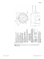
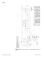
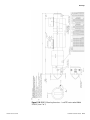
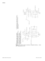
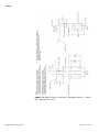
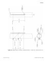
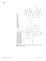
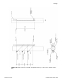
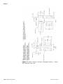
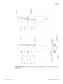
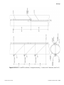
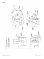
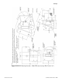
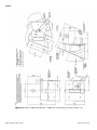
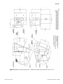
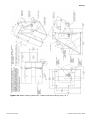
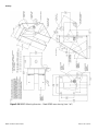
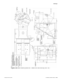
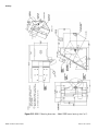
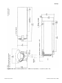
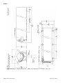
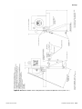
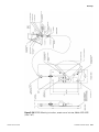
Refer to drawings 868502 and 868672 (868674 for water-cooled units) for
mounting dimensions of the detector-transmitter.
The source housing and detector are normally installed across the diameter
of the vessel. If mechanisms internal to the process vessel would interrupt
the radiation beam, you can move the installation slightly off center.
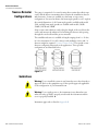
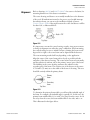
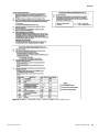
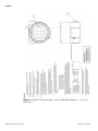
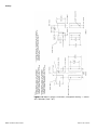
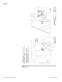
Contact Thermo Fisher if the angle between the source and detector will be
less than 130°, as illustrated below.
Figure 3–2.
It is important to mount the source housing securely, since any movement
or change in alignment can affect the gauge’s calibration. When mounting
the source housing, be sure to include a means of aiming the beam several
degrees left or right so the source beam can be aligned with the detector.
The exact mounting method will vary depending on the application.
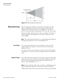
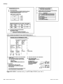
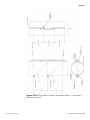
Align the center of the source beam path as closely as possible with the
centerline of the detector housing. The source beam is narrow horizontally,
and the radiation is uniform only in the primary (center) part of the beam.
The shielding in the source housing attenuates the radiation in the
secondary part of the beam. The sensitive area of the detector is the center
2-7/8 inches (73 mm) across the width of the detector’s housing. This area
should lie entirely within the primary beam.
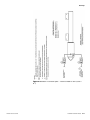
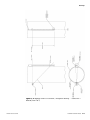
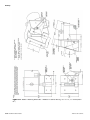
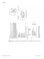
Figure 3–3.
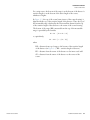
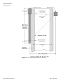
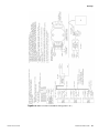
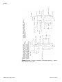
To determine the primary beam width, you will need the included angle of
the beam. For example, the included angle is typically 12°. In this case, the
primary beam width will be 1 foot wide 5 feet away from the source. At 10
feet away from the source, the beam width will be 2 feet wide, and so on.
This is illustrated in the figure below.
Thermo Fisher Scientific
LevelPRO Installation Guide
3-5