1
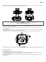
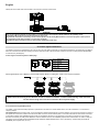
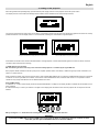
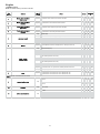
Infinity Wash M
instruction manual
manuale di istruzioni
Version 2.1
DIS128
∞Infinity Wash M
Serial number/numero di serie
Date of purchase/data di acquisto
Retailer/fornitore
Address/indirizzo
Suburb/cap/città
Capital city/provincial
State/stato
Tel./fax
Please note in the space provided above the relative service information of the model and the
retailer from whom you purchased your Infinity Wash M: this information will assist us in providing
spare parts, repairs or in answering any technical enquiries with the utmost speed and accuracy.
Prendete nota, nello spazio apposite, dei dati relative al modello e al rivenditore del vostro Infinity
Wash M: questi dati ci permetteranno di assistervi con la massima rapidità e precisione.
WARNING: the security of the fixture is granted only if these instructions are strictly followed;
therefore it is absolutely necessary to keep this manual.
ATTENZIONE: la sicurezza dell’apparecchio è garantita solo con l’uso appropriato delle presenti
istruzioni, pertanto è necessario conservarle.
User Manual Version 2.1
edition March 2012
English
Index
1.Packaging and transportation ..............................................................................................................................................................................6
1.1 Packaging......................................................................................................................................................................................................... 6
1.2 Trasportation .................................................................................................................................................................................................... 6
2. General information .............................................................................................................................................................................................6
2.1 Important safety information. ............................................................................................................................................................................6
2.2 Warranty conditions ..........................................................................................................................................................................................7
2.3 EC Norms ......................................................................................................................................................................................................... 7
3. Product specifications .........................................................................................................................................................................................7
3.1 Technical characteristics...................................................................................................................................................................................7
3.2 Dimensions.......................................................................................................................................................................................................7
3.3 Projector Components ......................................................................................................................................................................................8
4. Installation ............................................................................................................................................................................................................ 8
4.1 Mechanical installation......................................................................................................................................................................................8
4.2 Safety connection .............................................................................................................................................................................................9
5. Powering up ..........................................................................................................................................................................................................9
5.1 Connecting to mains power ..............................................................................................................................................................................9
6. Control signal connections................................................................................................................................................................................ 10
6.1 Connection through ArtNet.protocol ................................................................................................................................................................10
7. Turning on the projector ....................................................................................................................................................................................11
7.1 DMX address of the projector .........................................................................................................................................................................11
7.2 DMX functions ................................................................................................................................................................................................12
8. Display panel functions .....................................................................................................................................................................................14
8.1 Quick guide to menù .......................................................................................................................................................................................14
8.2 Rapid count ....................................................................................................................................................................................................14
8.3 Main functions ................................................................................................................................................................................................15
8.4 Measures........................................................................................................................................................................................................17
8.5 Display setup .................................................................................................................................................................................................. 17
8.6 Demo mode ....................................................................................................................................................................................................18
8.7 Special mode and electronic motor alignment ................................................................................................................................................. 18
9. Lamp installation and alignment ....................................................................................................................................................................... 20
9.1 Lamp installation.............................................................................................................................................................................................20
9.2 Aligning the lamp in the optical path................................................................................................................................................................21
9.3 Halogen lamp operations ................................................................................................................................................................................ 21
9.4 Turning back to discharge lamp (700W or 575W) ........................................................................................................................................... 22
10. Operating on inside groups .............................................................................................................................................................................23
10.1 How to open the projector .............................................................................................................................................................................23
10.2 How to extract the gobos and colour changer assembly. .............................................................................................................................. 23
10.3 Standard color wheel configuration ...............................................................................................................................................................24
10.4 How to replace filters ....................................................................................................................................................................................24
10.5 Standard effect wheel configuration .............................................................................................................................................................. 25
10.6 How to replace effects ..................................................................................................................................................................................25
10.7 Reassembly the groups on the projector .......................................................................................................................................................25
11. Maintenance...................................................................................................................................................................................................... 26
11.1 Periodic cleaning ..........................................................................................................................................................................................26
11.2 Periodic maintenance ...................................................................................................................................................................................26
11.3 Fuse replacement .........................................................................................................................................................................................26
12. Spare parts........................................................................................................................................................................................................26
12.1 Spare parts ...................................................................................................................................................................................................26
13. Error messages ................................................................................................................................................................................................27
14. Frequently asked questions ............................................................................................................................................................................28
5
English
Congratulations on having purchased a Coemar product. You have assured yourself of a fixture of the highest quality, both in the componentry and
in the technology used. We renew our invitation to you to complete the service information form on the previous page. This will assist in providing
prompt and accurate advice from your Coemar service centre, which you can thoroughly trust and to which you can submit any requests for service
or information. Following the instructions and procedures outlined in this manual will ensure the maximum efficiency of this product for years to
come.
1.Packaging and transportation
1.1 Packaging
Open the packaging and make sure that no part of the equipment has suffered any damage during the transportation. In case of damage to the
fixture, contact your currier and your supplier immediately by telephone, fax or email, and inform them you will formally notify them in writing
through registered letter.
Packing List
Make sure the packaging contains:
1 the Infinity Wash M projector.
2 the instruction manual.
3 the Cam-Lock support brackets.
1.2 Trasportation
The Infinity Wash M must be transported exclusively in its original packaging or in an appropriate flight case.
2. General information
2.1 Important safety information.
Fire prevention:
1.Infinity Wash M utilizes a Philips MSR 700 Gold Mini Fast Fit or a Philips MSR Gold 575 MiniFast Fit lamp, the use of any alternative lamp might
be risky and will make the warranty of the fixture null and void.
2. Never locate the fixture on any flammable surface.
3. Minimum distance from flammable materials: 0.5m.
4. Minimum distance from the closest illuminable surface: 0.5m.
5. Replace any blown or damaged fuses only with identical ones, both in size and value. Refer to the connection diagram if there is any doubt.
6. Connect the projector to mains power protected by a thermal magnetic circuit breaker.
Preventing electric shock:
1. Presence of high voltage inside of the fixture. Insulate the projector from mains supply before opening or performing any function which involves
touching the inside of the fixture, including lamp replacement.
2. For the connection to the mains, adhere strictly to the guidelines outlined in this manual..
3. The level of technology of Infinity Wash M requires the use of specialised personnel for all service applications; refer all work to your
authorised Coemar service centre.
4. A good earth connection is essential for the proper functioning of the projector. Never connect the fixture if there is no earth connection.
5. Mains cables must not come into contact with other cables.
6. Do not operate the projector with wet hands or in an area where water is present.
7. The fixture must never be located in an exposed position, or in areas of extreme humidity.
Protection against ultraviolet radiation(UV):
1. Never turn on the lamp if any of the lenses, filters, or the plastic housing are damaged; their shielding functions will only operate efficiently if they
are in perfect working order.
2. Never look directly in the direction of the lamp when it is operating.
Safety:
1. The projector must always be installed with bolts, clamps, or other fixing devices which are suitably rated to support the weight of the projector.
2. Always use a secondary safety fixing device with chain or steel wire of a suitable rating to sustain the weight of the unit in case of failure of the
principal fixing point.
3. The external surfaces of the unit, at various points, may reach 150°C. Never handle the unit until at least 10 minutes have elapsed since the lamp
was turned off
4. Always replace the lamp if any physical damage is evident.
5. Never install the fixture in an enclosed area lacking sufficient air flow; the room temperature must not exceed 35°C.
6. Wait at least 10 minutes after the unit has been turned off before attempting to replace or remove the lamp. Always use protection gloves while
replacing the lamp.
7. The projector contains electronic and electrical components which must under no circumstances be in contact with water, oil or any other liquid.
Failure to do so will compromise the proper functioning of the projector.
Projector movement.
The projector has a pan range of 540° in its base and a tilt range 262° in its yoke; do not obstruct the projector whilst it is moving.
Forced ventilation
On the body of the projector you will note several air vents housing several cooling fans, both in the basis and in the body. To avoid any problems
associated with overheating, never obstruct any of these vents, as this would seriously compromise the proper operation of the unit.
Protection rating against penetration by external agents:
The fixture is classified as an ordinary apparatus ; its protection grade against penetration by external agents, solid or liquid, is IP20.
6
English
2.2 Warranty conditions
1. The fixture is guaranteed for a period of 12 months from the date of purchase against manufacturing or materials defects.
2. The warranty does not extend to damage caused by inappropriate usage, use by inexperienced operators or inadequate maintenance.
3. The warranty is immediately void if the projector has been tampered or opened by unauthorised personnel.
4. The warranty does not extend to fixture replacement.
5. Both the serial number and the model of the projector are required for any advice or service from your authorised service centre.
2.3 EC Norms
The projector meets all fundamental applicable EC requirements.
3. Product specifications
3.1 Technical characteristics
700 W
Power
Maximum current
4,5 A
4A.
Cos ϕ = 0,9
Power factor
Lamp Wattage
575 W
90-260 Vac 50/60Hz Autosensing
700 W
Maximum room temperature
575 W
35°C/95°F
Weight
25 Kg./55 lbs
IP rating
IP20
3.2 Dimensions
7
English
3.3 Projector Components
D
E
Components description
C
B
F
A
L
A
B
C
D
E
F
G
H
I
L
Front lens assembly
Zoom assembly
Colour changer assembly
Lamp assembly
Body casing
Yoke
Base casing
Base
Camlock plate
Body
G
H
I
4. Installation
4.1 Mechanical installation
Infinity Wash M may be either floor or ceiling mounted. It may also be installed on a structure. The unit is provided with four rubber feet mounted
on its base, allowing it to be placed on a flat surface. For installations on a reticular structure, Coemar provides a set of Cam-lock support brackets,
which are included in the packaging. The Cam-lock bracket is one-fourth-turn supports. Before using it for supporting the projector, make sure that it
is correctly seated and firmly tightened into position).
8
English
For installations on a reticular structure, we recommend using specific “C” hooks, suitable for supporting the weight. Normally, the “C” hooks are
tightened in the central hole of the cam-lock brackets, as shown in the picture below.
WARNING !
Always make sure that both the structure and the fixing devices (screws, clamps etc.)
are suitable for holding the weight of the unit.
The structure must also be sufficiently rigid so as not to move or shake whilst the Infinity Wash M projector moves during its operation. Make sure
that the supporting structure is not subject to torsion.
Do not install the projector in locations readily accessible by unauthorised or untrained personnel who is not aware of these safety instructions.
4.2 Safety connection
If the Infinity Wash M is fixed to a structure, the use of a safety chain is recommended in order to meet the current relevant safety standards. The
safety chain must pass through the holes “A” and then fixed to the structure itself.
If using steel wires or chains which have not been manufactured by Coemar, make sure that they are suitable for holding the weight of the unit.
A
5. Powering up
5.1 Connecting to mains power
Mains cable characteristics
The mains cable provided is complying with the most recent standards.
NB: In case of cable replacement, similar cable with comparable thermal resistant qualities must be used exclusively (cable 3X 1,5 ø external 10
mm, rated voltage 300/500V, test voltage 2 KV, operation temperature -40°C + 180°C, Coemar cod. CV5311).
Connection to mains power
For connection to mains, use a connector of a suitable rating to sustain the maximum current: 200/208/230/240 Vac 8 amps constant current in
normal operation.
9
English
Identify the mains cable which exits the base of the unit and connect as shown below.
WARNING !
• The use of a thermal magnetic circuit breaker is recommended for each projector. Strictly adhere to all regulatory norms.
• Infinity Wash M cannot be powered through Dimmer power units.
• A good earth connection is necessary for the correct operation of the Infinity Wash M. Never connect the projector to main power if
the green/yellow earth cable provided is not correctly connected.
• All cable and plug connections must be carried out by qualified personnel only.
6. Control signal connections
The digital control signal is transmitted to the projector via a two pole cable screened as per international standards for the transmission of DMX512
data. The connection must be serial, utilising connectors XLR3 and XLR5, male and female, located on the base of Infinity Wash M labelled DMX
512 IN and OUT (see diagram)
Control signal connection by XLR3 e XLR5 plugs
Pin 1= GROUND
Pin 2= DATAPin 3= DATA+
Pin 4= NC
Pin 5= NC
When signal arrives from a DMX 512 console with Cannon XLR5 ( 5 poles) pins 4 and 5 must not be connected.
WARNING !
Make sure that screening and conductors are not in contact one another or with the metal housing of the connector.
Pin n# 1 and housing must never be connected to the unit power supply.
6.1 Connection through ArtNet.protocol
The ArtNet protocol allows enabled projectors to operate and to be seen as a normal network device, such as a standard P.C. connected to a
company network.
Infinity Wash M leaves the factory ready to be connected to an ArtNet network without any further settings. Just connect the projector by means of
the specific RJ45 connector located on the side of the DMX connectors and the relative patch to a common HUB Ethernet which will be connected
to an ArtNet controller. Each Coemar projector has its own IP address, therefore it is not necessary to set it when connecting it to the network.
Should it be necessary to modify the IP address for reasons related to the net, each Coemar projector allows customization. In order to modify the
net setting, access the MAIN FUNCTION/PROJECTOR CONTROL MODE/ARTNET ONLY menu ( alternatively, Artnet to DMX) /CUSTOM IP
ADDRESS (see complete menu, art. 8.3).
10
English
7. Turning on the projector
After having followed the preceding steps, proceed with the power supply and turn on the projector via the main power switch.
The display will show a short welcome message and the software version installed on the internal microprocessors:
The projector will perform the reset function on all motors. This operation will last a few seconds, thus allowing the digital control motors to correctly
position themselves. Then the display will turn on in a fixed mode, indicating the correct DMX 512 signal reception.
During the reset function the display will blink for a few seconds….
…then the DMX address of the projector will appear
If the address continues to blink and the “NO DMX SIGNAL” message appears, it means that the DMX signal has not been received. Check the
connection cable and the mixer functioning.
7.1 DMX address of the projector
NB: The following section is valid only in the case where Infinity Spot XL is controlled by the signal DMX 512.
Each projector utilises 18 address channels (16 bit) for its complete operation and is controlled by a DMX 512 signal (for further information, see
section 7.2, DMX functions).
When powered up initially, each projector will show A001, which indicates DMX address 001; a projector thus addressed will respond to commands
of channel 1 to 18 from your DMX 512 controller. A second unit must be addressed as A019, a third as A039 and so on. The operation must be
carried out every Infinity Wash M which has an address different from A001.
Altering DMX address
1. Press the + or – button until the display shows the required DMX address. The digits on the display will blink to indicate that the variation has not
been registered.
2. Press the enter key to confirm your selection. The digits on the display panel will cease to blink and the projector will now respond to the new
address.
NB: by holding the + or – button down the scrolling will be faster; thus allowing a faster selection
WARNING!
If you alter the DMX address with no DMX signal connected, the digits on the display panel will continue to flash
even after you have pressed ENTER button to confirm the address.
11
English
7.2 DMX functions
Note: the default setting is 16 bit/24 channels
dmx
c hannel
func tion
1
X axis, base mov ement
(pan) c oarse
2
dec imal
perc entag
e
proportional proportional coarse control of the base motor movement
0
- 255
0% - 100%
X axis, base mov ement
(pan) fine
proportional proportional fine control of the base motor movement
0
- 255
0% - 100%
3
Y axis, yok e mov ement
(tilt) c oarse
proportional proportional coarse control of the yoke motor movement
0
- 255
0% - 100%
4
Y axis, yok e mov ement
(tilt) fine
proportional proportional fine control of the yoke motor movement
0
- 255
0% - 100%
0
- 10
0% - 4%
11 - 25
4% - 10%
5
mov ement speed
type of
c ontrol
step
standard (fast)
step
ultra fast movement (best for programming positions)
proportional vector mode (from fast to slow)
26 - 127 10% - 50%
proportional tracking mode (from fast to slow)
128 - 247 50% - 97%
step
6
dimmer
effec t
smooth mode
248 - 255 97% - 100%
proportional gradual adjustment of luminous intensity from 0 to 100% (see channel 17)
step
shutter closed (zap off)
proportional
7
strobe, shutter
and zap effec t
step
proportional
step
8
zoom
proportional
0
0% - 100%
- 9
0% - 4%
4% - 26%
shutter open (zap off)
67 - 68
26% - 27%
sequenced pulse effect, slow closing, fast opening
(with variable speed from slow to fast)
69 - 125 27% - 49%
shutter open (zap off)
126 - 127 49% - 50%
sequenced pulse effect, fast closing, slow opening
(with variable speed from fast to slow)
128 - 184 50% - 72%
shutter open (zap off)
185 - 187 73% - 73%
proportional random strobe effect, non-synchronised, variable speed from slow to fast
step
- 255
10 - 66
proportional strobe effect with variable speed from slow to fast
step
0
shutter open (zap off)
188 - 244 74% - 96%
245 - 255 96% - 100%
proportional zoom control from narrow 13° to wide beam 26° (2X)
proportional zoom control from narrow 18° to wide beam 42° (3X)
0
- 255
0% - 100%
zoom 2X
0
- 128
0% - 50%
Note 1: zoom 2X / 3X is selectable from channel 9
9
zoom selec tion range
step
zoom 3X
10
11
no effec t
effec t wheel selec tion
step
step
129 - 255 51% - 100%
spare channel
0
- 0
0% - 0%
no effect
0
- 10
0% - 4%
effect 1
11 - 92
effect 2
93 - 174 36% - 68%
effect 3
175 - 255 69% - 100%
12
4%
36%
English
step
no effect
0
proportional proportional indexing of the effect through 360°
12
indexing effec t rotation through 360°
proportional
step
proportional
step
c olors selec tion
from the c olor wheel
13
proportional
- 10
0% - 4%
11 - 127
4% - 50%
continuous rotation of the effect in a clockwise direction with
proportional control over decreasing speed
128 - 190 50% - 75%
stop effect rotation
191 - 192 75% - 75%
continuous rotation of the effect in a counter-clockwise direction with
proportional control over increasing speed
193 - 255 76% - 100%
white beam
0
- 5
0% - 2%
color 1
6
- 14
2% - 5%
color 2
15 - 22
6% - 9%
color 3
23 - 30
9% - 12%
color 4
31 - 38
12% - 15%
color 5
39 - 45
15% - 18%
from white to white beam (color 1-2-3-4-5),
proportional positions
46 - 127 18% - 50%
rainbow effect from fast to slow in an counter-clockwise direction
128 - 190 50% - 75%
rainbow effect from slow to fast in a clockwise direction
191 - 255 75% - 100%
14
c yan
proportional
proportional control of the percentage of cyan color in the light beam
from 0 to 100%
0
- 255
0% - 100%
15
magenta
proportional
proportional control of the percentage of magenta color in the light beam
from 0 to 100%
0
- 255
0% - 100%
16
yellow
proportional
proportional control of the percentage of yellow color in the light beam
from 0 to 100%
0
- 255
0% - 100%
no effect
0
- 10
0% - 4%
zap effect synchronised with the strobe effect,
speed and mode selected by strobe channel 7
11 - 30
4% - 12%
zap effect, flicker and speed adjustable,
speed and mode selected by strobe channel 7
31 - 249 12% - 98%
black-out of the light beam during PAN/ TILT movement, colors wheel
and effects wheel
250 - 255 98% - 100%
17
17
zap effec t
(effect varies depending upon channel 7 strobe)
halogen dimmer c urv e
(effect varies depending upon channel 6 dimmer)
step
step
standard dimmer (mechanical)
0
- 10
0% - 4%
the mechanical dimmer works in sync with the dimming of the lamp
11 - 30
4% - 12%
the mechanical dimmer has no effect and is active only that the halogen lamp
(variable color temperature)
31 - 249 12% - 98%
black-out of the light beam during PAN/ TILT movement, gobos wheel, colors wheel
and effects wheel
250 - 255 98% - 100%
Note 2: when using halogen lamp, channel 17 allow the selection of the curve which can be a combination of the characteristic dimming lamp and/ or mechanical dimmer
lamp on/ off and
motors reset
18
step
park, no function
0
- 9
0% - 4%
lamp off
10 - 29
4% - 11%
pan and tilt reset (once only)
30 - 65
12% - 25%
all motor reset exept black out, pan and tilt (once only)
66 - 100 26% - 39%
all motor reset exept black out (once only)
101 - 135 40% - 53%
reset of all the motors (once only)
136 - 170 53% - 67%
LCD display off
171 - 185 67% - 73%
LCD display on
186 - 199 73% - 78%
lamp on
200 - 255 78% - 100%
Note 3: the LCD panel may be used to disable the switc hing off of the lamp v ia DMX
Note 4: turning off the lamp and all reset func tions are delayed by 6 sec onds to prev ent ac c idental ac tiv ation
Note 5: the lamp on/ off func tion c an only be effec ted if an opposite lev el is set
Projec tor:
InfinityWash M
T able number: 294
T able name: DMX 512 func tions
Edition: 3 Date: 20/ 06/ 2011
13
English
8. Display panel functions
By suitably using all the functions of Infinity Wash M, which can be activated through its display panel, it is possible to change some of the
parameters and to add some functions.
Changing the preset settings made by Coemar can vary the functions of the projector so that it will respond differently to the controller; therefore
carefully read about the functions described hereunder before carrying out any possible selection.
8.1 Quick guide to menù
In order to access the functions, just press the menu button: the screen you see hereunder, divided into four sections, will appear; the sections will
be shown cyclically, one by one, every time the + or – button is pressed. To select the desired function, press enter.
DISPLAY SETUP-allows the management
of:
-brightness
-positive or negative graphic
-backlight shutdown time.
-buttons shutdown time.
- 180° reading of the display
MEASURES- allows the reading of all
DISPLAY
SETUP
MAIN
FUNCTIONS
MEASURES
DEMO
MAIN FUNCTIONS: groups the main setup
functions of the fixture: pan/tilt
management, lamp management, fans
management, reset, motors test, ID code,
back to original settings and access to
“SPECIAL MODE “.
DEMO- allows the performing of the
demonstration program. 4 different demo
programs are available.
functional settings of the fixture:
temperatures, fans power, DMX channels
values, diagnostics, lamp status and life
and diagnostic version of the installed
software.
8.2 Rapid count
By the display panel of Infinity Wash M It is possible to rapidly change the various numbers displayed for the different functions in the following 3
manners:
1.Pressing the + or – buttons will cause the count to be quicker.
2.Pressing first + and then – and then holding them down simultaneously will cause the numbers to jump to the highest value.
3.Pressing first – and then + and then holding them down simultaneously will cause the numbers to jump to the lowest value.
14
English
8.3 Main functions
The projector gives the opportunity to change and customize some functional settings.
MAIN FUNCTIONS
PAN/TILT
See diagram in
at next page
It allows the complete management of the horizontal and vertical
movements..
CMY SETTING
-Standard
-Emulation
-Special
It allows to choose an alternative colour insertion curve.
DIMMER SETTING
-Tungsten
-Xenon
It allows to simulate dimming features of a Tungsten lamp or a Xenon lamp.
-Normal
-High
-NORMAL: fans are controleld by pcb in function of the internal temperature.
-HIGH:fans are always set at full power.
-On
-Standard
-STANDARD: the on/off state of the lamp’ s controller by DMX signal..
-ON: the lamp remains always on (please, see DMX chart).
-All
-Pan/Tilt only
-Effect Only
It perform the reset function of the fixture.
Keeping pressed ENTER and MENU buttons during reset ,
it will access SPECIAL MODE (see special mode menu).
FANS MODE CONTROL
LAMP STRIKE DMX
RESET
RECALL DEFAULT
SETTING
ZAP EFFECT ENABLE
ID CODE
<<Are you sure ?>>
-On
-Off
from 1 to #
Restores all the functional settings (excepts for
address, motors, tuning and odometers) to default
values.
Enables or disables the lamp’s “zap”
effect.
It allows to move and
check every single
motor without using
DMX signal. SAVE
ALL allows to store
the motors position
until next fixture’s
start up.
-Pan
-Tilt
Lets you set the ID code of the fixture
by using + or – buttons.
-Dimmer
-Shutter
TEST MOTORS
-Zoom
-DMX only
PROJECTOR CONTROL
MODE
-ARTnet only
-ARTnet to DMX
BALLAST SETTING
-Zoom select range
Default IP address
Custom IP address
Universe address
MAC address
It allows to configure
the fixture to be
controlled by
ARTnet protocol.
Default IP address
Custom IP address
Universe address
MAC address
It allows to control
the fixture setted in
a DMX chain by
ARTnet controller.
-Effect wheel
-Effect rotation
-Color wheel
-Cyan
-Magenta
-Yellow
-Lamp type
-575 W lamp power
-700 W lamp power
-Output frequency
-Hz value
-Reset Temp max
<<Are you sure ?>>
15
-Zap effect
-Save all
It resets the ballast’s
temperature value.
English
The following diagram explains the sub menu for the management of pan eand tilt, regarding the pan/tilt menu item descrive in the diagram at
previous page.
-Clockwise
-Counterclockwise
It inverts the horizontal beam direction, from
left to right or vice-versa by the same DMX
change.
PAN/TILT
PAN DIRECTION
CMY SETTING
PAN ANGLE
DIMMER SETTING
TILT DIRECTION
-Clockwise
-Counterclockwise
GOBOS
OPTO ENCODER
ENABLE
Pan/Tilt
-On
-Off
Pan only
-On
-Off
Tilt only
-On
-Off
Pan/Tilt
-On
-Off
- 540°
- 400°
IRIS
Panoramic working mode that reduces rotating angle from
540° to 400°.
It inverts the vertical moving beam direction,
from upwards to downwards or vice-versa by
the same DMX level change.
It allows to enable or disable the
optical sensors which check the
base’s or the yoke’s position (or
body) and perform the automatic
return if moved accidentally.
FANS MODE CONTROL
PAN/TILT MOVEMENT
ENABLE
LAMP STRIKE DMX
Pan only
-On
-Off
Tilt only
-On
-Off
RESET
RECALL DEFAULT
SETTING
ZAP EFFECT ENABLE
ID CODE
TEST MOTORS
PROJECTOR CONTROL
MODE
BALLAST SETTING
16
It allows to engage or disengage
the pan, the tilt or both movements.
It allows to start up the fixture into a
case or installed on a truss.
English
8.4 Measures
The internal microprocessor of the Infinity Wash M allows for several diagnostic and output parameters to be displayed.
MEASURES
TEMPERATURE
VOLTAGE
DMX INPUT MEASURE
DMX RATE
It shows the temperatures detected by the sensors in the base:
Tdriver, Tsens#1, Tsens#2, Tsens#3.
It measures main power voltage of the fans:
vmain, vboard, vfan1, vfan2, vfan3. Values over 28.5 V must be
considerated as abnormal.
Reading of the DMX value (0-255) received from each channel used by
the fixture on the DMX 512 line.
Reading of the typical value of the DMX signal called “RATE” (signal
update frequency in milliseconds).
It shows possible ongoing alarm messages.
ALARM STATUS
It shows lamp’s status on or with “zap effect” enabled.
LAMP STATUS
USAGE HOURS
SOFTWARE VERSION
BALLAST MEASURES
It shows fixture’s odometers: lamp life (r): lif e of the lamp (resettable),
lamp life: total life ao the lamps installed (not resettable), unit life:
fixture’s life.
It shows the actual installed software version:
sw LCD master: software installed on to LCD master board.
sw MOTOR slave: software installed on to MOTOR slave board .
It shows the operating information of the ballast:
Lamp type: installed lamp type (575 o 700 W).
Actual power: Instant power in W emitted from the ballast.
T1max, T2max: Max temperatures (resettable) detected by the ballast.
NStsk: lamp’s strike attempts with countdown.
8.5 Display setup
The display setup allows tot une the Infinity Wash M functions according to your needs. The following diagram shows the section features.
DISPLAY SETUP
DISPLAY REVERSE
-Standard
-Reverse
BACKGROUND
COLOR
-Standard
-Reverse
It allows 180° rotation of the display graphics in case of
upside-down installation of the fixture.
It allows visualization in negative or in positive of the display
graphics.
DISPLAY TIME OUT
-OFF
-# secs. (+/-)
It allows one to decide number of seconds before turning off
the display back light in case of inactivity. OFF value leaves
the backlight always on.
BUTTON TIME OUT
-OFF
-# secs. (+/-)
It allows setting up number of seconds buttons must be
pressed in order to activate functions. This function avoid
activation of features if buttons are pressed accidentally.
BRIGHTNESS
1~100% (+/-)
It allows setting of brightness of display back light..
17
English
8.6 Demo mode
Demo mode allows the fixture to perform up to 4 different demonstration programs Infinity Wash M.
DEMO
It performs a demonstrative program with all systems active.
DEMO FULL
DEMO FIX
DEMO COLOURS
DEMO EFFECT
It performs a demonstrative program without pan and tilt
movements.
It performs a demonstrative program using only colour
changer.
It performs a demonstrative program including only effects
features.
8.7 Special mode and electronic motor alignment
WARNING!
This section is for the exclusive use of qualified and experienced personnel.
SPECIAL MODE menu allows access to the electronic motor alignment section and to special functions, like lamp odometer reset, software upload
and download. To enter SPECIAL MODE reach the reset page in the MAIN FUNCTIONS menu, start reset choosing ALL and press simultaneously
enter and menu buttons for about 10 seconds.
WARNING!
The electronic tuning procedure is only possible when the DMX512 signal is on.
The display panel of Infinity Wash M allows the electronic motor alignment of the projector motors in the optical system; this procedure is
performed by Coemar at the factory during the testing: in order to obtain particular effects or in the case of internal components being replaced
(motors, electronic boards, sensors, etc.) it may be necessary to change this setting.
Altering the default settings performed by Coemar may radically alter the functioning of the projector. Carefully read all of the following functions
before trying to perform any operations.
Note: pressing the buttons + and – simultaneously the setting returns to 128 (default value).
18
English
SPECIAL MODE
MOTOR
ADJUSTMENT
PAN
TILT
DIMMER
SHUTTER
ZOOM
ZOOM LENS
EFFECT WHEEL
EFFECT INDEX
COLOR WHEEL
CYAN
MAGENTA
YELLOW
EXIT
Pan movement alignment.
Tilt movement alignment.
Dimmer alignment.
Shutter alignment.
Zoom lens alignment.
2nd zoom lens alignment.
Effect wheel alignment.
Radial alignment of the effects located on the
prism wheel..
Colour wheel alignment.
Cyan filter alignment.
Magenta filter alignment.
Yellow filter alignment.
It stores the settings and closes the procedure.
SPECIAL FUNCTIONS
It restores to 0 the resettabile lamp’s electronic
odometer visible also in MEASURES menu. It
must be restored each time the lamp being
changed in order to get a correct reading of
lamp’s life.
LAMP HOURS RESET
<<Are you sure ?>>
DOWNLOAD
LCD MASTER
<<Are you sure ?>>
It makes the fixture ready to transfer the LCD
software on to the PC.
DOWNLOAD
MOT. SLAVE
<<Are you sure ?>>
It make the fixture ready to transfer the MOTORS
software on to the PC..
UPLOAD
LCD MASTER
<<Are you sure ?>>
It makes the fixture ready to receive the LCD
software from the PC.
UPLOAD
MOT. SLAVE
<<Are you sure ?>>
It makes the fixture ready to receive the MOTORS
software from the PC.
19
English
9. Lamp installation and alignment
Infinity M utilizes a Philips MSR GOLD 700/2 Mini Fast Fit with PGJX28 base lamp.at maximum power of 700 W or a Philips MSR GOLD 575/2
Mini Fast Fit with adequate ballast setting.(menù MAIN FUNCTIONS/BALLAST SETTINGS). These lamps are available as a spare part at your
Coemar’s distributor or service centre.
Lamp
Philips MSR Gold 700/2 Mini Fast Fit
Coemar code
Power range
Philips MSR Gold 575/2 Mini Fast Fit
Q750W 100V TAL halogen
105830
700 W (full power), 400W (low power)
Lighting flow
50000 lm
Color temp.
7200°K
105831
BC10013B001
575 W (full power), 400 W (low power)
750W
35600 lm
21500lm
7400 °K
3200 °K
Base
PGJX28
Life
750 h.
200 h
WARNING !
Balast setting and lamp replacement must be done by qualified personnel.
Disconnect the unit from main power prior to attempting lamp’s installation or replacement.
The fixture internal temperature can reach 250° C after 5 minutes, and reach a peak of 350 °C; make sure that the lamp is cold before trying to
remove it. In any case the fixture can be opened only 10 minutes after turning off the lamp.
The lamp is of the mercury vapour type with discharge ignition. This type of lamp operates at high internal pressure, and a slight risk of explosion
exists if the lamp is operated beyond its recommended life. Therefore, we recommend to replace the lamp within the specified lamp life. Always
handle the lamp with care avoiding to touch it with bare hands.
9.1 Lamp installation
1. Use a suitable tool to loosen the 2 fixing screws A of the lamp holder cover at the rear of the projector body.
2. Remove the lamp holder cover “B”.
3. Insert the lamp into the holder and gently rotate it clockwise until it blocks.
4.Una volta in sede, ruotate la lampada in senso orario fino a bloccarla. The lamp used is made of quartz glass and must be handled with care;
always adhere to the instructions provided in the lamp packaging. Never touch the glass directly, use the polythene wrapping provided in the lamp
packaging. DO NOT USE UNDUE FORCE ON THE GLASS.
5. Insert the lamp holder cover in its original position and screw the 2 screws “A” back in.
-
WARNING !
Never use undue force if the procedure becomes difficult.
Never put pressure on the glass of the lamp.
Never touch the glass of the lamp with bare hands.
A
B
WARNING !
Each time you replace the lamp, we recommend the following operations.
• realign the lamp in the optical system in order to avoid dichroic filters overheating and consequent effects.
• reset the lamp odometer to obtain reliable information about the residual life of the lamp.
20
English
9.2 Aligning the lamp in the optical path
Aligning the lamp in the optical system is achieved via the 3 adjusters at the rear of the projector. This procedure should be undertaken to maximize
output, to avoid the possible overheating of the internal components due to the incorrect focusing of the beam onto components not predisposed to
high temperature. It is extremely important to obtain a uniform distribution of light on all beams.
Alignment procedure
Alignment is carried out by using the 3 screws A, B and C showed in the picture below. The lamp should be on, black-out and dimmer fully open,
and no colours selected. If the lamp is not correctly aligned, a hot-spot to the most central part of the beam possible and then flatten the beam to
maximum uniformity. The combined regulation of the three adjusters allows horizontal, vertical and axial regulation of the lamp.
9.3 Halogen lamp operations
Previous to install the lamp, you should ensure that your Infinity M has the software required to manage the new features.
Keep pressed, while turning on the unit, “+” and “-“ keys, the display shows a screen like this:
Version configuration
Situation
Action
A
INFINITY __M
-SW LCD:
2.10.00
-SW MOTORS:
2.04.00
-LDR LCD:
1.40
-LDR MOTORS:
1.40
-SW BALLAST:
1.70
The halogen lamp cannot be
installed because the ballast is not
suitable. (SW ballast version must
be successive to 1.70)
Replace the ballast with kit
BC10013B002 and upgrade
LCD and MOT software.
B
INFINITY __M
-SW LCD:
2.12.00
-SW MOTORS:
2.08.00
-LDR LCD:
1.40
-LDR MOTORS:
1.40
-SW BALLAST:
1.80
The ballast is suitable for the
halogen lamp but it is
recommendable update the ballast
software to version 3.70
Update ballast software using
DR1+.
In order to upgrade the software on your Infinity M, DR1+ device is strictly required.
Provide yourself with this product if you do not have it. After you have installed DR1 + Lite Interface on your PC and you have correctly connected
PC, DR1+ device to Infinity M (remember that in the case you are using a laptop PC you should drive USB patch trough a self-powered USB Hub),
you are ready to perform the software installation on Infinity M that can vary regarding the two cases mentioned in the previous chapter:
Case “A”: You’ll have to replace the ballast with KIT BC10013B002; this one will come with the correct hardware and software version (3.70), then
you’ll have to upgrade LCD and MOTORS software to LCD 2.13 and MOTORS 2.09. These software versions are available in the CD included in
this kit. Refer to DR1+ user manual to learn how to perform the software upgrade.
Case “B”: You’ll have to upgrade the ballast software to 3.70. This operation is slightly different respect LCD and MOTOR software upgrade.
1-Go with the mouse on the fixture you have to upgrade in the left column of DR1+ Lite Interface.
2-Keep pressed ALT+CTRL+SHIFT and click the right button of the mouse; a pop up menu will appear.
3-Keeping pressed ALT+CTRL+SHIFT Click on SEND COMMAND-SERVICE MENU-SHOW BALLAST. In the list you should now see the ballast
device you are going to upload the software on.
4-Upgrade the software ( you’ll find the 3.70 file in the CD ROM included) in the same way you did for LCD or MOT.
5-In order to return to fixtures list, repeat the operation in step 3 clicking HIDE BALLAST instead of SHOW BALLAST.
6- Check that software versions are updated LCD at 2.12 and MOT 2.09
21
English
WARNING !
• after the installation of this lamp and each time you replace it, we recommend the following operations.
• realign the lamp in the optical system in order to avoid dichroic filters overheating and consequent effects.
• reset the lamp odometer to obtain reliable information about the residual life of the lamp.
9.4 Turning back to discharge lamp (700W or 575W)
This is a very important chapter if you are going to replace the halogen lamp for the 700W (OEM configuration) or 575 W lamp. Please
read it carefully and ensure you have understood the topics.
The transition from discharge lamp (700 or 575W) to halogen lamp requires no settings, in fact the equipment recognizes the type of lamp and set
automatically. The reverse operation ( halogen to 700/575W) requires that the projector’s setting matches the type of lamp we are going to install;
for example, if your Infinity M was set to work with 700W lamp before the transition to halogen, you are going to install a 575W lamp and you forget
to set Infinity M, when you’ll turn the lamp on, the projector will be damaged. Follow these hints to change the lamp safely:
1 Install the discharge lamp.
2 Turn on Infinity M keeping pressed MENU ENTER e “+” and follow the instruction to change the lamp setting..
3 Turn on again the projector and look at the display, Infinity M will delay the turning on of the lamp to give you the opportunity to check the type of
lamp set .
.>>> WARNING:<<<
.>>> WARNING:<<<
Current MH lamp
setting is 700 W
PLEASE CHECK
CORRECT SETTING
Current MH lamp
setting is 575W
PLEASE CHECK
CORRECT SETTING
The system warns you that Infinity M has been set to work with 700 W
metal halide discharge lamp.
The system warns you that Infinity M has been set to work with 575 W
metal halide discharge lamp.
4 Check that the setting matches the lamp you’ve installed; if it doesn’t match, turn off immediately the unit and repeat the procedure described
above.
5 Once made the correct setting, turn on Infinity M, turn on the lamp and don’t forget to adjust it.
Dimmer mode explanation
Halogen dimmer curve channel
(see DMX chart above)
Dimmer/shutter status
Lamp status
time
Minimum power
0 seconds
off
5 minutes
Minimum power
10 seconds
off
5 minutes
off
0 seconds
Minimum power
10 seconds
off
5 minutes
Minimum power
10 seconds
off
5 minutes
Minimum power
10 seconds
off
5 minutes
Dimmer closed
Mechanical dimmer works in sync with the
dimming of the lamp
Shutter closed
Mechanical dimmer has no effect and is active
only that the halogen lamp (variable color
temperature)
Dimmer closed
Shutter closed
Dimmer closed
Black-out of the light beam during PAN/TILT
movement, gobos wheel, colors wheel and effect
wheel.
Shutter closed
22
English
10. Operating on inside groups
The fixture allows the extraction of both gobos and colour changer assemblies in order to facilitate inspection, gobos replacing and clearing of
colour filters and lenses.
WARNING !
The following procedures should be undertaken by qualified and experienced technical personnel.
Handle with extreme care !
Always disconnect al cables before proceeding and ensure that the unit is sufficiently cool.
10.1 How to open the projector
Using an appropriate screwdriver, remove screws “A” from the upper housing and remove this. In order to identify the upper housing to be removed,
position the unit so that the printing on the lamp holder group can be read (the printing must not upside down). Once this operation has been carried
out, block the movement of the body through the specific device and proceed with the removal of the upper housing.
A
10.2 How to extract the gobos and colour changer assembly.
1.Remove “B” screws of the connectors labeled “gobos” and “color changer” and gently remove the “C” connector.
2.Remove “D” screws of the two assembly, manually shift forward the zooms lenses.
3.Gently extract a few centimeters the gobos assembly, tilt it forward.
4.Now, gently extract the colour changer assembly.
5.Finally extract the gobos assembly partially extracted in the step above..
D
B
C
23
English
10.3 Standard color wheel configuration
40mm.
CODE
POS.
ROSCO STANDARD
N°
VT358
1
026 Bright red
1
VT352
2
022 Dark Amber
1
FC049
3
441 Full CT straw
1
VT356
4
089 Moss green
1
VT354
5
079 Just blue
1
10.4 How to replace filters
1. Facing the front side of the wheel, push up the filter to replace inserting your finger through the plate hole, then remove the filter.
2.Insert the new filter (facing the coated side downwards) making it slip under the spring until it locks; respect the coated side of the filter (bottom
side)..
NB:The wheel only accepts glass filters or gobos with a maximum diameter of 40 mm and no more thick than 1 mm.
24
English
10.5 Standard effect wheel configuration
CODE/CODICE
POS.
DESCRIPRION
N°PCS
VT281
1
Beam shape
1
LEPR25
2
Beam ‘O
1
LEPR32
3
Moon flower
1
10.6 How to replace effects
1.Lift and gently extract from the wheel the support which contains the effect you are going to replace.
2.Slide the new support under the spring, making sure that it enters in place through the two pins on the back of the support.
10.7 Reassembly the groups on the projector
In order to reassemble the projector, just follow backwards the procedure explained at the beginning of this chapter, Insert with care the colour
changer, then fix the group and its connector by their screws. Verify that the internal of the body is free from loose pieces ( washers, screws, etc..)
then fix the body cover.
25
English
11. Maintenance
11.1 Periodic cleaning
Lenses and filters
Even a fine layer of dust can reduce the luminous output and alter the compactness of the beam. Regularly clean all filters and lenses using a soft
cotton cloth, dampened with a specialist lens cleaning solution.
Fans and air passages
The fans and air passages must be cleaned approximately every 8 weeks; the length of the period between each cleaning will depend, of course,
upon the conditions in which the projector is operating. Suitable instruments for performing this type of maintenance are a brush and a common
vacuum cleaner or an air compressor.
If necessary, do not hesitate to carry this out even after a shorter period of time.
11.2 Periodic maintenance
Lamp
Check the lamp and replace it if there is any observable damage or deformation or if or if the time limit is close (check the resettable counter).
Mechanical parts
Periodically check the movement of all mechanical devices, and check driving belts, gears and lens guides. Replace them if necessary. Make sure
the projector is not mechanically damaged. If necessary, replace the worn parts. Check the tension of the belts and adjust them if necessary.
Electrical components
Check all electrical connections, in particular for correct earthing and correct attachment of all extractable connectors. Press the connectors if
necessary and reposition as before.
11.3 Fuse replacement
Check the conditions of the fuses using an appropriate instrument; if damaged, replace them with equivalent ones.
12. Spare parts
12.1 Spare parts
All the components of Infinity Wash M are available as replacement spares from your authorized Coemar service centre. Accurate description of
the fixture, model number and type will assist us in providing for your requirements in an efficient and effective manner.
26
English
13. Error messages
If you have to check a malfunction, Infinity Wash M has an auto diagnostic system that visualizes in the lower part of the display one or more
intermittent messages, preceded by “ERR”.
The following table will help you to understand these messages correctly. If the problem persists despite carrying out the suggested procedure,
contact your Coemar Customer Service Centre.
Error mesage
Description and suggested solution
ERR: Memory FAILURE
Internal memory writing error. Contact your authorized Coemar Service centre..
ERR: CFG data FAILURE
Configuration data error. The initial parameter setting has failed, the projector has loaded its factory default setting. Turn the
projector off and on again. Should the error reoccur, refer to your authorised Coemar service centre.
ERR: DMX address
DMX addressing error. The projector is not receiving all DMX channels needed to operate correctly. Check the DMX address
indicated on the display and the number of channels being output from the controller (some controllers do not exceed 12
channels)
ERR: DMX frame
DMX frame error. DMX signal present but frame too short; the controller has not enough channels to control the projector.
ERR: No Slave LINK
Communication error . The LCD board is not communicating properly with the main board. Check the cabling connecting the
boards or refer to your authorised Coemar service centre.
ERR: No Ballast LINK
Communication error. The LCD board is not communicating properly with the ballast. Check the cabling connecting the
boards or refer to your authorised Coemar service centre.
ERR: Ballast Temp. #1
Primary ballast temperature too high. Check that the ambient temperature does not exceed 40°C check also the proper
functioning of the fans.
ERR: Ballast Temp.#2
Secondary ballast temperature too high. Check that the ambient temperature does not exceed 40°C check also the proper
functioning of the fans.
ERR: Vinp line low
Too low main power input. Main power voltage is too low, it must be at least 90 Vac.
ERR: Vout lamp high
Too high lamp voltage . Lamp can be exhausted and so consume more power than normal. Replace the lamp and if needed,
refer to your authorised Coemar service centre.
ERR: Encoder PAN
PAN encoder not found. Check the sensor on the encoder wheel placed at the base to detect the position of the PAN
movement motor; check the motor and the relevant cabling
ERR: Encoder TILT
TILT encoder not found. Check the sensor of the encoder wheel placed on the fixture’s yoke to detect the position of the TILT
movement motor; check the motor and the relevant cabling
ERR: Sensors Line #2
Sensor line 2 error Control circuit error relating to position sensors for the motors (EFFECTS) posta nella forcella: il sensore
non rileva il magnete. The sensor does not detect the magnet. Check sensor and motor cabling of the Gobos assembly.
ERR: Sensors Line #5
Sensor line 5 error Control circuit error relating to position sensors for the motors of the colour changer assembly. The sensor
does not detect the magnet. Check sensor and motor cabling of the colour changer assembly.
ERR: EFFECT Wheel
Position error of the effect wheel. The sensor does not detect the magnet. Check the functioning and the correct positioning
of the magnetic sensor of the effect wheel.
ERR: EFFECT Index
Initial position error of the effect. The sensor does not detect the magnet. Check the functioning and the correct positioning
of the magnetic sensor placed on effect #1.
ERR: COLOR Wheel
Position error of the color wheel. The sensor does not detect the magnet. Check the functioning and the correct positioning
of the magnetic sensor of the colour wheel. Check the correct tightening of the transmission belt.
ERR: ZOOM
Zoom error. The sensor does not detect the magnet. Check the functioning and the correct positioning of the magnetic sensor
placed on the Zoom lens carriage. Check the correct tightening of the transmission belt.
27
English
14. Frequently asked questions
Question
Possible cause
Suggested solution
The projector is completely still.
-Projector not powered up:
The circuit breaker is switched off.
The protection fuse is blown.
Check that the mains power cable is
connected to power.
Set the circuit breaker to ON.
Disconnect the projector and replace the
fuse.
The projector resets correctly, but either
does not respond, or responds
incorerctly, to DMX signal.
Incorrect signal connection.
Incorrect DMX address.
Inspect the signal cable, rectify any
incorrect wiring, repair or replace any
damaged cables or connectors.
Check the DMX address.
The lamp functions intermittently or does
not turn on at all.
The projector is too hot.
Let the fixture cool down.
Check that the air vents above the
cooling fans are not obstructed and that
the fans are working correctly.
Ensure that the ambient temperature is
below 35°C
Projection brightness appears reduced
Lamp may be exhausted or not properly
aligned to optical path.
Replace the lamp if exhausted.
Align the lamp to optical path.
Information on disposal of the equipment
The equipment at the end of its useful life must be disposed of at an appropriate recycling center for
waste electrical and electronic equipment. The treatment and disposal of environmentally friendly, helps
prevent potential negative environmental and health and promote the reuse and / or recycling of
materials making up the equipment. Illegal disposal by the user includes the application of administrative
sanctions provided by law.
28
Coemar s.p.a.
via Inghilterra 2/A - 46042 Castel Goffredo (Mantova) Italy
ph. +39 0376/77521 - fax +39 0376/780657
[email protected]
Coemar si riserva il diritto di apportare modifiche senza preavviso.
Coemar reserves the right to effect modifications without notification