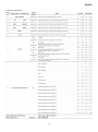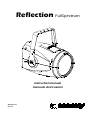
1
Reflection FullSpectrum
instruction manual
manuale di istruzioni
Version 1.0
DIS132
Reflection FullSpectrum
Serial number/numero di serie
Date of purchase/data di acquisto
Retailer/fornitore
Address/indirizzo
Suburb/cap/città
Capital city/provincial
State/stato
Tel./fax
Please note in the space provided above the relative service information of the model and the
retailer from whom you purchased your Reflection: this information will assist us in providing spare
parts, repairs or in answering any technical enquiries with the utmost speed and accuracy.
Prendete nota, nello spazio apposite, dei dati relative al modello e al rivenditore del vostro
Reflection questi dati ci permetteranno di assistervi con la massima rapidità e precisione.
WARNING: the security of the fixture is granted only if these instructions are strictly followed;
therefore it is absolutely necessary to keep this manual.
ATTENZIONE: la sicurezza dell’apparecchio è garantita solo con l’uso appropriato delle presenti
istruzioni, pertanto è necessario conservarle.
User Manual Version 1.0
edition January 2011
English
Index
1.Packaging and transportation ....................................................................................................................................................... 5
1.1 Packaging ................................................................................................................................................................................. 5
1.2 Trasportation ............................................................................................................................................................................. 5
2. General information ...................................................................................................................................................................... 5
2.1 Important safety information...................................................................................................................................................... 5
2.2 Warranty conditions. ................................................................................................................................................................. 5
2.3 EC norms. ................................................................................................................................................................................. 5
3. Product specifications .................................................................................................................................................................. 6
3.1 Technical characteristics ........................................................................................................................................................... 6
3.2 Dimensions ............................................................................................................................................................................... 6
3.3 Unit’s main components ............................................................................................................................................................ 7
4. Installation ..................................................................................................................................................................................... 7
4.1 Mechanical installation .............................................................................................................................................................. 7
4.2 Safety chain .............................................................................................................................................................................. 8
4.3 Adjusting unit’s tilt ..................................................................................................................................................................... 9
5. Powering up ................................................................................................................................................................................... 9
5.1 Operating voltage and frequency. ............................................................................................................................................. 9
5.2 Connection to mains power....................................................................................................................................................... 9
6. Control signal connections ........................................................................................................................................................ 10
6.1 Control signal connection by XLR5 plugs................................................................................................................................ 10
7. Turning on the projector ............................................................................................................................................................. 11
7.1 DMX address of the unit.......................................................................................................................................................... 11
7.2 DMX functions ......................................................................................................................................................................... 12
8. Display panel functions .............................................................................................................................................................. 15
8.1 Quick guide to menù ............................................................................................................................................................... 15
8.2 Rapid count ............................................................................................................................................................................. 15
8.3 Main function menu (Main functions) ...................................................................................................................................... 16
8.4 Tests and measures (Measures)............................................................................................................................................. 18
8.5 Display settings (Display Setup) ............................................................................................................................................. 19
8.6 User settings (Mode) ............................................................................................................................................................... 19
8.7 Connecting DR1 and DR1 Plus ............................................................................................................................................... 20
8.8 Electronic alignment of the leds. ............................................................................................................................................. 20
9. Error messages ........................................................................................................................................................................... 22
10.Accessories and spare parts ..................................................................................................................................................... 22
10.1 How to fix the optional accessories holder ............................................................................................................................ 23
11. Maintenance ............................................................................................................................................................................... 23
11.1 Periodic clearing.................................................................................................................................................................... 23
11.2 Special controls ..................................................................................................................................................................... 23
11.3 Fuses: ................................................................................................................................................................................... 24
12. F.A.Q. and answers ................................................................................................................................................................... 24
4
English
Congratulations on having purchased a Coemar product. You have assured yourself of a fixture of the highest quality, both in the
componentry and in the technology used. We renew our invitation to you to complete the service information form on the previous
page. This will assist in providing prompt and accurate advice from your Coemar service centre, which you can thoroughly trust and
to which you can submit any requests for service or information. Following the instructions and procedures outlined in this manual
will ensure the maximum efficiency of this product for years to come.
1.Packaging and transportation
1.1 Packaging
Open the packaging and make sure that no part of the equipment has suffered any damage during the transportation. In case of
damage to the fixture, contact your currier and your supplier immediately by telephone, fax or email, and inform them you will
formally notify them in writing through registered letter.
Packing List
Make sure the packaging contains:
1 Reflection
2 This instruction manual.
3-main power plugs
1.2 Trasportation
Reflection must be transported exclusively in its original packaging or in an appropriate flight case.
2. General information
2.1 Important safety information.
Fire prevention:
1.Never locate the fixture on any flammable surface.
2.Minimum distance from flammable materials: 0,5m.
3.Minimum distance from the closet illuminable surface: 0,5m.
4.Replace any blown or damaged fuse only with those of identical values. Refer to the schematic diagram if there is any doubt.
5. Connect the projector to mains power protected by a thermal magnetic circuit breaker.
Preventing from electric shock.
1. Presence of high voltage inside of the fixture. Insulate the projector from mains supply before opening or performing any function
which involves touching the inside of the fixture, including lamp replacement..
2. For the connection to the mains, adhere strictly to the guidelines outlined in this manual.
3. The level of technology of Reflection requires the use of specialised personnel for all service applications; refer all work to your
authorised Coemar service centre.
4. A good earth connection is essential for the proper functioning of the projector. Never connect the fixture if there is no earth
connection.
5.Mains cables must not come into contact with other cables.
6.Do not operate the projector with wet hands or in an area where water is present.
7.The fixture must never be located in an exposed position, or in areas of extreme humidity.
Safety.
1. The projector must always be installed with bolts, clamps, or other fixing devices which are suitably rated to support the weight of
the projector.
2. Always use a secondary safety fixing device with chain or steel wire of a suitable rating to sustain the weight of the unit in case of
failure of the principal fixing point.
3. The external surfaces of the unit, at various points, may reach 60°C. Never handle the unit until at least 10 minutes have elapsed
since the lamp was turned off
4. Never install the fixture in an enclosed area lacking sufficient air flow; the room temperature must not exceed 35°C.
5. The projector contains electronic and electrical components which must under no circumstances be in contact with water, oil or
any other liquid. Failure to do so will compromise the proper functioning of the projector.
2.2 Warranty conditions
1. The fixture is guaranteed for a period of 12 months from the date of purchase against manufacturing or materials defects.
2. The warranty does not extend to damage caused by inappropriate usage, use by inexperienced operators or inadequate
maintenance.
3. The warranty is immediately void if the projector has been tampered or opened by unauthorized personnel.
4. The warranty does not extend to fixture replacement.
5. Both the serial number and the model of the projector are required for any advice or service from your authorised service centre.
2.3 EC norms
The projector meets all fundamental applicable EC requirements.
5
English
3. Product specifications
3.1 Technical characteristics
Power
90-250 Vac 50/60Hz Autosensing
Maximum current
0,88 A @230 Vac, - 2,14 A @115Vac
Cos ϕ = 0,94
194 W
Power factor
Power
Maximum room temperature
35°C/95°F
Weight
12,5 Kg./27.5 lbs
Grado di protezione
IP20
The innovative core of Reflection consists of a reflection system with a source made of powerful leds in it which casts a compact
beam in infinite colors combination without any defect that any other classic multi lens led projector gives. Reflection has also an
automatic zoom system that allows to modify the beam width.
3.2 Dimensions
6
English
3.3 Unit’s main components
Components description
1- Yoke
6- Light source
2- Upper casing
7- Polycarbonate screen
3- Rear header and electronic sector
8- Yoke lock handle
4- Cooling sector
9- Lower casing
5- Mirror
4. Installation
4.1 Mechanical installation
Reflection may be floor mounted or hung from an appropriate structure in any position.
If hanging the fixture from a lighting truss or similar, we recommend the use of an appropriate clamp “B”, as shown in the following
diagram.
B
7
English
WARNING!
Always ensure that your support structure and fixing (bolts, clamps, etc…)
are rated to support the weight of the fixture.
Floor installation
If the fixture is floor mounted, we recommend the using of the standard yoke which can be opened for allow an adequate support
for the floor.
4.2 Safety chain
When hanging Reflection we recommend the use of a safety chain affine to the body and to the suspension device. The safety
chain should be either a metal rope or a metal chain, both suitably for the purpose.
In the case that the chain used is not producted by Coemar, ensure that it can bear the weight of the whole unit.
8
English
4.3 Adjusting unit’s tilt
In order to adjust the tilt of the unit laying on the floor or hanged on a truss, simply untight the side handle adjust the tilt and lock the
yoke again by tightening the handle again.
WARNING !
The unit never should be used upside-down; .the arrows printed on the back of the unit indicate its upper side, do not
use the unit if the arrows aim downwards. The unit allows an excursion angle of 150°.
5. Powering up
5.1 Operating voltage and frequency.
The unit may operates at voltages ranges from 90 to 250VaC at a frequency of 50 or 60 Hz. It is not needed to effect any setup
procedures: Reflection will automatically adjust its operation to suit any frequency or voltage within this range.
5.2 Connection to mains power
Mains cable characteristics
The mains cable provided is thermally resistant, complying to the most recent International standards.
Note: in case of cable replacement, similar cable with comparable thermal resistant qualities must be used exclusively (cable 3 X
1,5 ø external 10 mm, rated 300/500V, tested to 2 KV, operating temperature -40°C + 180°C, Coemar cod. CV5311).
Connection to mains power
Reflection is equipped with two power connectors, one as input and one as output, which can be used to connect more fixtures in
series (no more than 16 units @ 230V or 8 units @ 115V.).
The max absorption of Reflection is reported in the following table:
-230/240V 0,88 A constant during normal exercise.
-100/115V 2,14 A constant during normal exercise.
WARNING !
Never link more than 16 units at 230 V or 8 units at 115 V.
9
English
In the following figure you can see an example of series connection:
WARNING!
• The use of a thermal/magnetic circuit breaker is recommended. Strict adherence to regulatory norms is strongly
recommended.
•Reflection should not be powered through a dimmer as this may damage the internal switching power supply.
• Prior to connecting the device to mains power, ensure that the mains characteristics are within the recommended range
for use with Reflection.
• All cabling and connections should be carried out by suitably qualified personnel.
6. Control signal connections
6.1 Control signal connection by XLR5 plugs.
The digital control signal is transmitted to the projector via a two pole cable screened as per International standards for the
transmission of DMX 512 data. The connection must be serial, using connectors XL5 male and female located on the back of
Reflection labelled DMX512 IN e OUT (see diagram).
Pin 1= GROUND
Pin 2= DATAPin 3= DATA+
Pin 4 =nc
Pin 5 =nc
10
English
WARNING !
Make sure that screening and conductors are not in contact one another or with the metal housing of the connector.
Pin#1 and housing never must be connected to the power supply unit.
7. Turning on the projector
After having followed the preceding steps described, proceed with the power supply and turn on the projector connecting it to the
mains power.
The software version installed on the internal microprocessors will be shown on the display.
Reflection then, will promptly start the reset procedure; the operation will take some seconds allowing the correct positioning of the
motor. At the end of the procedure the display will stop blinking and will show the current DMX addressing.
During reset the display will blink for some seconds….
…then will appear DMX addressing of the unit
If the address continues to blink and the “NO DMX SIGNAL” message appears, it means that the DMX signal has not been
received. Check the connection cable and the mixer functioning.
7.1 DMX address of the unit
Each projector uses 12 DMX channels (16 bits mode) for its complete operation and is controlled by a DMX 512 signal (for further
information, see section 7.2, DMX functions).
DMX addressing
When powered up initially, each projector will show A001, which indicates DMX address 001; a projector thus addressed will
respond to commands of channels 1 to 12 from your DMX 512 controller (or from 1 to 8 at 8 bits), A second unit must be addressed
as A013 ( or A009), a third one as A025 (or A17) and so on. The operation must be carried out on every Reflection which has an
address different from A001..
Altering DMX address.
1. Press the + or – button until the display shows the required DMX address. The digits on the display will blink to indicate that the
variation has not been registered.
2. Press the enter key to confirm your selection. The digits on the display panel will cease to blink and the projector will now
respond to the new address.
Note: by holding the + or – button down the scrolling will be faster; thus allowing a faster selection
WARNING!
If you alter the DMX address with no DMX signal connected, the digits on the display panel will continue to flash
even after you have pressed ENTER button to confirm the address.
11
English
7.2 DMX functions
To set the configuration access the menu MAIN FUNCTIONS/DMX CHANNELS
12 channels configuration
12
English
13
English
8 channels configuration
14
English
8. Display panel functions
By suitably using all the functions of Reflection, which can be activated through its display panel, it is possible to change some of
the parameters and to add some functions.
Changing the preset settings made by Coemar can vary the functions of the projector so that it will respond differently to the
controller; therefore carefully read about the functions described here before carrying out any possible selection..
8.1 Quick guide to menù
In order to access the functions, just press the menu button: one after the other, all the voices of the menu will be cyclically shown
each time the key + or – will be pressed. To select the desired function, press enter.
8.2 Rapid count
By the display panel of Reflection It is possible to quickly change the various numbers displayed for the different functions in the
following 3 manners:
1.Pressing the + or – buttons will cause the count to be quicker.
2.Pressing first + and then – and then holding them down simultaneously will cause the numbers to jump to the highest value.
3.Pressing first – and then + and then holding them down simultaneously will cause the numbers to jump to the lowest value.
15
English
8.3 Main function menu (Main functions)
The projector gives the opportunity to change and customize some functional settings.
MAIN FUNCTIONS
DIMMER SETTING
-TUNGSTEN
-XENON
Dimmer behaviour, it simulates dimmer effect with tungsten
lamp or Xenon lamp.
It allows to choose primary colors
and emulate classic CMY filter
system in a large range of tones
without dmx signal.
See diagram below.
-RGB SETTING
COLOR SETTING
-CMY SETTING
It allows to change color
temperature of white light from
3200 °K to 9000 °K without dmx
signal.
See diagram below.
TEST
RED/CYAN
REFLECTION
A001
GREEN/MAGEN
RED DIMMER
BLUE/YELLOW
WHITE
REFLECTION
A001
ZOOM
ZOOM
STROBE
-Save all
It allows to cast primary colors
and check motor’s functioning
without dmx SIGNAL.
SAVE ALL stores all settings
until next power on.
See” *” for visualization.
REFLECTION
A001
STROBE
-On
-Off
It allows to provide the leds with a short current peak to get
the typical “blinder” feature.
- 8 channels
- 12 channels
It allows to select the 8 channels DMX mode without color
tones or 12 channels extended mode with selection and
color mixing.
DISABLE MAX
CALIBRATION
-On
-Off
It disabile the MAX alignment of the leds and sets them to
maximum value.
FANS MODE
-Silence
-Auto
-High
RESET
-enter
BOOSTER
Dmx Channel
RECALL DEFAULT
SETTING
ID CODE
<<Are you sure
Da 1 a n°
-SILENCE: fans and cooling pump work at minimum.
-AUTO: the work of fans and pump are regulated by PCB in function
of the temperature measured.
It start the reset procedure of the zoom motor.
Keep pressed ENTER and MENU buttons during reset to access to
SPECIAL MODE.
It resores all settings to the default settings with exception of
alignments, addressing and unit’s hours counter.
It sets the ID number of the unit. Use + and – buttons and ENTER to
confirm.
16
English
*Visualization examples
REFLECTION
A001
REFLECTION
A001
REFLECTION
SCARLET RED
LIGHT GREEN
WHITE
RGB
CMY
A001
8000 K
-RED TONE
SCARLET RED 24
RED SALMON 40
DEEP SALMON 42
LIGHT RED 26
-GREEN TONE
PRIMARY GREEN
TURQUOISE 92
BLUE GREEN 93
LIGHT GREEN 88
-BLUE TONE
PRIMARY BLUE 80
MEDIUM BLUE 83
BLUE INDIGO 59
CONGO BLUE 382
-WHITE TONE
WHITE 9000°K
WHITE 6500°K
WHITE 4500°K
WHITE 3200°K
-CYAN TONE
CYAN 4307
CYAN 4330
CYAN 4390
CYAN 2005
-MAGENTA
MAGENTA 4715
MAGENTA 4730
MAGENTA 4760
MAGENTA
-YELLOW TONE
YELLOW 4560
GALLO GOLD 316
YELLOW FLAME 18
ORANGE 23
-WHITE TONE
WHITE 9000°K
WHITE 7500°K
WHITE 4500°K
WHITE 3200°K
-Save all
17
English
8.4 Tests and measures (Measures)
The internal microprocessor of Reflection allows for several diagnostic and output paramenter to be displayed.
MEASURES
TEMPERATURE
VOLTAGE
DMX INPUT MEASURE
DMX RATE
ALARM STATUS
LED STATUS
LED FREQUENCY
USAGE HOURS
SOFTWARE VERSION
It shows temperature measured by the sensors in the unit:
Tboard, Tled, Tdriver, Tsens.
It shows the values in Volt of the mains power, the fans and pump: Valim,
Vrad, Vfan, Vpump.
It shows the DMX value(0-255) received on each DMX channel used by
the unit on the DMX chain.
Reading of the typical DMX value called RATE ( frequency of signal
updating in milliseconds).
It shows the error message of the alarm in progress.
RED: 80%
GREEN: 30%
BLUE: 10%
WHITE: 100%
It shows the luminous efficiency of the RGBW
leds.
It shows the led’s emission frequency. It may be useful if frequency must
be set due to flicker issues.
It shows the led’s life values in hours: led life (r): led module life
(resettable); led life:life of total modules installed on the unit since now
(not resettable); unit life: life of the projector.
It shows the actual software version installed on the unit : sw master
Reflection..
18
English
8.5 Display settings (Display Setup)
The fixture allows to set the display visualization preferences .
DISPLAY SETUP
DISPLAY REVERSE
-Standard
-Reverse
BACKGROUND
COLOR
-Standard
-Reverse
It allows to turn 180° the reading of the display if the unit is hanged
upside down.
It allows visualization in negative or in positive of the display graphics.
DISPLAY TIME OUT
-OFF
-n° sec. (+/-)
It allows one to decide number of seconds before turning off the display
back light in case of inactivity. OFF value leaves the backlight always
on.
BUTTON TIME OUT
-OFF
-n° sec. (+/-)
It allows setting up number of seconds buttons must be pressed in
order to activate functions. This function avoid activation of features if
buttons are pressed accidentally.
BRIGHTNESS
1~100% (+/-)
It allows setting of brightness of display back light..
8.6 User settings (Mode)
The fixture permits three functional modes: DMX, MASTER and SLAVE.
MODE
DMX only
A001
MASTER
PROGRAM 1
PROGRAM
selection
It restores to DMX the functioning
of the unit.
It sets the unit as MASTER and
launches a demo program.
PROGRAM 1
PROGRAM 4
PROGRAM ALL
SPEED
selection
0,1sec
60sec
WAIT
selection
0,1sec
210sec
Speed of program’s step
execution.
Wait time between the
program’s steps.
It sets the unit as SLAVE.
SLAVE
19
English
8.7 Connecting DR1 and DR1 Plus
All features are available in the menu can also be activated by DR1 (code CO9707) and DR1 Plus (cod.CO9709). DR1 and DR1
Plus is a tool designed for technicians who can operate the apparatus at the same time the programmer of the show, without
having to physically intervene on headlamps, but controlling functions remotely.
For example, DR1 and DR1 Plus eliminates the need to change a DMX address on the unit, (thus avoiding the technical climbing
on the structure) and can read hours of lamp life and other functions normally accessible from the display. DR1 and DR1 Plus also
allows updating the firmware of the projectors.
To enable a projector to work with DR1 or DR1 Plus, you must set each unit of the line with its own, unique identity number (ID).
WARNING !
-If you set as identification number "0 ", Reflection will not be recognized by DR1 and DR1 Plus
-Never assign the same ID to two or more units of a same DMX line. This causes the failure of the system. (DR1 and DR1
Plus will display an error message).
For more information see the manual for DR1 or DR1 Plus.
8.8 Electronic alignment of the leds.
The display panel of Reflection allows the electronic alignment of the leds, this procedure is performed by Coemar at the time of
testing, this procedure may be useful for special effects or in case of replacement of internal components (PCBs, leds, etc. ...).
Altering the settings made by Coemar may radically alter the functioning of the projector’s functions.
Carefully read the following prior to attempting any changes.
WARNING !
This chapter should be considered for the exclusive use of technicians and highly skilled staff.
To access alignement function:
Activate the reset holding down the MENU and ENTER for at least 10 seconds. Screen is then displayed "SPECIAL MODE"
WARNING !
The electronic alignment procedure is only possible with DMX512 signal .
20
English
See the folowing diagram to enter in the function’s details..
SPECIAL MODE
LED and MOTOR
ADJUSTMENT
WARNING!
This function is available only with DMX signal connected and
by perform the reset while keep pressed ENTER and MENU
buttons together for about 10 seconds.
min RED
min GREEN
Red leds alignment at minimum intensity.
Green leds alignment at minimum intensity.
min BLUE
Blue leds alignment at minimum intensity.
min WHITE
White leds alignment at minimum intensity.
max RED
Red leds alignment at maximum intensity.
max GREEN
Green leds alignment at maximum intensity.
max BLUE
Blue leds alignment at maximum intensity.
max WHITE
White leds alignment at maximum intensity.
ZOOM
EXIT
Zoom motor alignment.
It stores the settings and exits from the procedure.
SPECIAL FUNCTIONS
WORKING TIME RESET
<<Are you sure ?>>
It allows to rest the hours meter of the led module
also viewable in MEASURES menu. It should be
reset whenever the led module has been replaced
in order to give precise information on the
duration.
DOWNLOAD
SOFTWARE
<<Are you sure ?>>
It makes the unit ready for the storing of the
software on to the PC.
UPLOAD
SOFTWARE
<<Are you sure ?>>
It makes the unit ready to receive the software
from the PC.
Nota: Simultaneously pressing + and – buttons will return the calibration value to 128 (default).
UPLD Function (Upload)
this function allows to upgrade the firmware of Reflection only by DR1 or DR1 Plus and a Personal Computer. Read DR1 or DR1
Plus manual for further information.
DULD Function (Download)
this function allows to download the software from Reflection only by DR1 or DR1 Plus and by a Personal Computer. Read DR1 or
DR1 Plus manual for further information.
21
English
9. Error messages
If a malfunction occurs, Reflection has a self-diagnostic system that will show the error message on the display. The following
table will explain in detail the most common errors. If, despite of suggested intervention, the problem persists, call the Coemar
Service center near you.
Error message
Description and suggested solution.
Eeprom Failure
The initial configuration settings are faulty or have been loaded incorrectly. The unit has loaded its default
configuration. Turn the unit off and on again and if the error persists, it means that the Eeprom is defective.
Refer to your Coemar service center for the servicing.
CFG data Failure
The electronics of the unit found problems in loading data from Eeprom: it does not load custom settings but
default factory settings. Contact your Coemar Service Center near you.
DMX address
The unit is not receiving all the DMX channels necessary for its operation. Check the DMX address and the
control console operation. Note that some controllers may not generate all 512 channels of signal.
DMX signal present but frame too short; the controller has not enough channels to control the projector.
DMX frame
Internal FAN
The rear fan is damaged or stuck. Turn off the unit then turn it on again and if the error persist contact your
Coemar Service Center near you.
Radiator FAN
The internal cooling fan is damaged or stuck. Turn off the unit then turn it on again and if the error persist
contact your Coemar Service Center near you.
Pump FAILURE
The pump of the cooling system is damaged or stuck. Turn off the unit then turn it on again and if the error
persist contact your Coemar Service Center near you.
Over TEMPERATURE
The light source has reached the maximum allowable temperature and so the unit shuts off . Check for water
level in the cooling circuit , check fans and pump’s functioning.
10.Accessories and spare parts
Reflection is a very versatile fixture, optional accessories for its customization are available under request:
Coemar order code
Description
CO002
4 blades barndoor
BC10001A000
Accessories holder
CO001
Standard size gel frame
All the components of Reflection are available as spare parts from your Coemar dealer or Service. Accurate description of the
fixture, model number and type will assist us in providing for your requirements in an efficient and effective manner
22
English
10.1 How to fix the optional accessories holder
1 Open the upper casing of the unit by unscrewing the 4 screws, temporary remove the two side plates “A”.
2 Insert the gel frame holder in site as explained in the picture and fix again the two plates “A” .
3 Close the unit by repeating to the contrary the step 1 of this procedure.
11. Maintenance
11.1 Periodic clearing
Polycarbonate screen
Even a fine layer of dust can reduce the luminous output and alter the compactness of the beam. Regularly clean all filters and
lenses using a soft cotton cloth, dampened with a specialist lens cleaning solution.
Cleaning of the unit
Use a soft brush or a common vacuum cleaner or a source of compressed air for removing dust. For the cleaning of the housing
use a soft cloth and a non-aggressive cleaner. Check that the internal fans and heat exchanger must be perfectly clean.
11.2 Special controls
How to top up the water tank ( to perform every 1500 hours ):
1 Open the upper casing of the unit by unscrewing the 4 screws.
2 Locate the water tank which is site in the back-right of the unit, beside the mirror
3 Remove the cap from the tank and fill it up to the edge with bi-distilled water avoiding the formation of air bubbles.
4 Close tight the tank’s cap.
WARNING !
-Periodically check the water level in the expansion
tank; the tank must always be totally full.
-Check that the cap is well tightened.
-The lack of refrigerant can cause heavy damage to
the leds so to require their replacement.
23
English
Mechanical parts
Check the correct working of the mechanical parts and, if needed, replace them. Make sure the projector is not mechanically
damaged. If necessary, replace the worn parts.
Electrical components
Check all electrical connections, in particular for correct grounding and correct attachment of all extractable connectors. Press the
connectors if necessary and reposition as before.
11.3 Fuses:
Reflection has an automatic fuse that in most cases does not need to be replaced.
12. F.A.Q. and answers
The following list shows common issues that may be simply solved. If issues persist, the unit must be repaired by qualified
personnel or just contact your Coemar service near you.
Question
Possible cause
-Projector not powered on:
Reflection does not power on.
Suggested solution
1-Make sure the power cord is plugged in
or test the input voltage.
Reflection does not answer to DMX
signal.
DMX signal may not reach Reflection .
Inspect the cable connection, correct
poor connections or inefficient repair or
replace damaged cables.
Check DMX address of the unit.
I set Reflection as MASTER unit but it
does not perform any program.
1-There is another unit set as MASTER.
2-The DMX signal is present.
3-Any program has not been set.
1-Search for the other MASTER unit and
set it as SLAVE
2-Remove eventual DMX patch.
3-Set a program on the MASTER unit.
Reflection is not recognized by DR1 Plus.
ID set to 0 or another unit in the chain is
set with the same number..
Set an ID number different from 0 and
from any other unit in the chain.
Information on disposal of the equipment
The equipment at the end of its useful life must be disposed of at an appropriate recycling center for
waste electrical and electronic equipment. The treatment and disposal of environmentally friendly, helps
prevent potential negative environmental and health and promote the reuse and / or recycling of
materials making up the equipment. Illegal disposal by the user includes the application of administrative
sanctions provided by law.
24
Coemar s.p.a.
via Inghilterra 2/A - 46042 Castel Goffredo (Mantova) Italy
ph. +39 0376/77521 - fax +39 0376/780657
[email protected]
Coemar si riserva il diritto di apportare modifiche senza preavviso.
Coemar reserves the right to effect modifications without notification