1
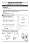
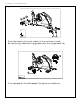
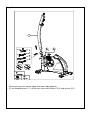
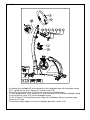
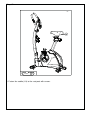
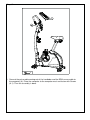
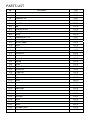
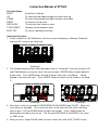
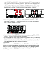
®
$VVHPEO\2SHUDWLQJ,QVWUXFWLRQV
IRU
3*0DJQHWLF%LNH
([SORGHGYLHZ
ASSEMBLY INSTRUCTIONS
Stage#1
1. Put on front stabilizer (H) and rear stabilizer (I) to the mainframe assembly.
Be noted: the front stabilizer has transportation wheel. Use carriage bolts(K-10),
curve washer (K-8) and crown nut (K-9) to fix the stabilizers tightly.
2. Fix the right pedal (D-15) and left pedal (D-16) tightly to the right/left crank.
Stage#2
1. Connect the tension control upper and lower cable together.
2. Fix the handlebar post ( C ) to the main frame with Screws (D-3) and washer (D-1).
Stage#3
0/
1. Assemble the handlebar (B) to the bracket on the handlebar post with handlebar clamp
(K-1), spring washer (K-3), washer (K-4) and screw (K-5).
2. Put out the hand pulse wire (B-3)from the hole on the handlebar post.
3. Fix the spring washer (K-3), washer (K-4) and metal bush (K-6) into the handlebar clamp.
Insert the plastic cover (K-2) to the handlebar clamp.
4. Fix the T-knob (K-7) to the plastic cover. Adjust the handlebar with your desired angle.
Fasten the T-knob.
5. Fix the water bottle holder(C-4) to the handlebar post with screws (C-3).
Stage#4
ǂǂ
0/
1. Settle the Seat Slider Seat(J-8) on the Seat Post (J) and tighten with the Flat washer(K-11) &
Seat Knob(J-5).
2. Assemble the Left & Right cover for slider (J-3 & J-4) and fix them with Screws (K-12).
Stage#5
Wrench
1. Fasten the saddle (J-9) to the seat post with screws.
Stage#6
1. Connect the pulse cable coming out of the handlebar and the RPM sensor cable to
the computer (A). Place the computer to the computer mast and fasten with Screws
(A-1). Then the assembly is done.
([SORGHGYLHZ
3$576/,67 No.
A
Description
Q'ty
Computer
1PCS
Screw
4PCS
Handlebar Set
1SET
B-1
Cap
2PCS
B-2
Hand Pulse
2PCS
B-3
Cap
1PCS
B-4
Hand pulse wire
1PCS
B-5
Foam grip
2PCS
B-6
Screw
2PCS
Handlebar post set
1SET
C-1
Sensor Upper
1PCS
C-2
Tension Upper
1PCS
C-3
Screw
2PCS
C-4
Bottle Holder
1PCS
Main Frame Set
1SET
D-1
Flat washer
4PCS
D-3
Screw
4PCS
D-4
Sensor Box
1PCS
D-5
Bearing
2PCS
D-6
Screw
1PCS
D-7
Sensor Bracket
1PCS
D-8
Flat washer
1PCS
D-9
C type ring
1PCS
D-10
Right front cover
1PCS
D-11
Right cover (Lower)
1PCS
D-12
Screw
10PCS
D-13
Cover for crank
2PCS
D-14
Right crank
1PCS
D-15
Pedal Right
1PCS
D-16
Pedal Left
1PCS
D-17
Nylok
2PCS
D-18
Left crank
1PCS
D-19
Screw
5PCS
D-20
Left front cover
1PCS
D-21
Screw
6PCS
D-22
Left upper cover
1PCS
D-23
Wave washer
1PCS
A-1
B
C
D
No.
Description
Q'ty
D-24
Flat washer
10PCS
D-25
Spring for idler
1PCS
D-26
Tension Lower
1PCS
D-27
Ring
2PCS
Flywheel Set
1SET
E-1
Washer
2PCS
E-2
Nut
5PCS
E-3
Bearing
1PCS
E-4
Flat washer
1PCS
E-5
Bearing
1PCS
E-6
One-way Bearing set
1PCS
E-7
Flywheel
1PCS
E-8
Axel for Flywheel
1PCS
E-9
Bearing
1PCS
E-10
Pulley
1PCS
E-11
Bearing
1PCS
E-12
Flat washer
1PCS
Idler set
1SET
F-1
Wave washer
2PCS
F-2
Idler wheel
1PCS
F-3
Hex screw
1PCS
F-4
Flat washer
1PCS
F-5
Flat washer
1PCS
F-6
Nylon Nut
1PCS
F-7
Flat washer
1PCS
F-8
Hex screw
1PCS
E
F
G
Axle Set
G-1
Bushing
1PCS
G-2
Pulley
1PCS
G-3
Axle
1PCS
G-4
Hex screw
3PCS
G-5
Belt
1PCS
H
Front Stabilzer Set
H-1
Screw
2PCS
H-2
End cap for front Stabilzer
1PCS
H-3
End cap for front Stabilzer
1PCS
I
Rear Stabilzer Set
I-1
End cap for front Stabilzer
2PCS
I-2
Adjustor
2PCS
No.
Hex screw
2PCS
J
Seat post
1SET
J-1
Sleeve
1PCS
J-2
Seat knob
1PCS
J-3
Left cover for slider
1PCS
J-4
Right cover for slider
1PCS
J-5
Seat knob
1PCS
J-6
Screw set for seat slider
1PCS
J-7
Cap
2PCS
J-8
Seat Slider Set
1PCS
J-9
Saddle
1PCS
Hardware Kit
1SET
K-1
Metal cover
1PCS
K-2
Plastic cover
1PCS
K-3
Flat washer
2PCS
K-4
2PCS
K-5
Spring washer
Screw
K-6
Bushing
1PCS
K-7
Screw for T-Knob
1PCS
K-8
Flat washer
4PCS
K-9
Nut
4PCS
K-10
Carriage Screw
4PCS
K-11
Flat washer
1PCS
K-12
Screw
4PCS
Magnetic Set
1SET
L
Q'ty
I-3
K
Description
1PCS
722/6
Wrench
ǂǂ
12.5HJXODU
:DVKHUǂ
12.0HWDOFRYHU
.&DUULDJH%ROW
0300
12.:DVKHU
ǂǂW
12.7VKDSHNQRE0/
12.ġ:DVKHU
ǂǂW
12.$FRUQ1XWIRU
0%ROW
.$OOHQ%ROW
0300
12.6SULQJ
:DVKHUǂ
12.%XVKLQJ
ǂ00
6FUHZGULYHU
%R[6SDQQHU
$OOHQ.H\
12.6FUHZV
0/
00
Instruction Manual of ST7603
Function Button
MODE
UP
To confirm all settings.
To select training mode and adjust function value up.
DOWN
RESET
RECOVERY
To select training mode and adjust function value down.
To clear the set-up value.
To test heart rate recovery status
TOTAL RESET
BODY FAT :
To power on the computer again.
To start or stop body fat testing.
Operation Procedure
1. Installs 2 pieces of 1.5V #3 batteries, then the screen will display as following “Drawing A”
and have “Bi” sound at the same time.
Drawing A
2. The calendar display will be in blinking mode shown as “Drawing B”, then you can press UP
and DOWN button to set up the value. You can also press RESET button to come back the
preset value. Press MODE button will skip to Month, Date, Hour, and Minute. Set-up
method is the same with year. Press “MODE” button to confirm set-up shown as “Drawing
C”.
Drawing B
Drawing C
3. Get access to the set-up mode of TIME/DISTANCE/CALORIES/Target PULSE. When you
are in each set- up mode. For instance the time set-up, when the time value is blinking,
you can press “UP and DOWN” button to adjust the number. Press “Mode” button for
confirmation and skip to next set-up. The set-up of DISTANCE & CALORIES is the same
as TIME set-up.
4. When you are in Target PULSE mode, the main screen will show ”AGE”, PULSE screen
show ”TARGET value (220-AGE)”. At the time you can press “SET” button to change the
value of AGE and TARGET shown as “Drawing D”. When the set-up is completed, press
“MODE” button to confirm and skip to TIME screen. Continuously press “MODE” button
will act this circle. If you do not enter the RPM and PULSE signal or manual set-up time
over 4 minutes in this mode, it will be skip to SLEEP mode shown as “Drawing E”.
Drawing D
Drawing E
5. After entering RPM value, and setting up the TIME, DISTANCE, CALORIES. In SCAN
mode shown as “Drawing F”. RPM/SPEED/TM/DIST/CAL/PULSE will skip to display in
every 6 seconds. The order is as follows.
Drawing F
6. You can also press “Mode” button to select single function display except RPM & SPEED
function. The RPM & SPEED function will switch display.
7. All function modes can set up, except the SPEED and RPM. When set-up is completed for
TIME, DISTANCE, CALORIES, TARGET, H.R., enter RPM, the monitor will count down till
00:00 is achieved, and come out 4 times “Bi” sound for 8 seconds, then the value will be
count up from 00:00 right away if you continue to exercise.
8. RECOVERY烉
(1)When the user presses “RECOVERY” button, the RECOVERY function is active. At this
time only PULSE and TIME is working, other functions will not be displayed, and the Sensor
Input is not available. TIME starts to count down from ”00烉
烉60”, Pulse signal will be blinking
according user’s heart rate BPM. When Time counts down to “0”, it will show F1~F6.
(2)LCD display as follows: (RECOVERY start condition & end condition)ˤ
(3)If the count down action to 00:00 is not completed and there is no pulse signal, the count
down action has to be done and shown F6.
(4)If you press the RECOVERY button prior to count down to 00:00, it will be end the function
and there will be no display at all.
FUNCTIONS烉
烉
SCAN:
Displays all function from RPMĺSPEEDĺDISTANCEĺCALORIESĺPULSE in
sequence.
RPM:
Displays the pedaling Rotation Per Minute. The RPM and SPEED will switch to
another display in every 6
seconds after exercise starts.
SPEED: Displays the user’s exercise speed.
TIME: 1.You can press Up / Down button to set target time between 00:00 to 99:00 for count
down function.
2.It can be set up by the user or accumulated automatically for count up function.
DISTANCE: 1.Your can press UP/Down button to set target distance between 00:00 to 99:00
for count down function.
2. It can be set up by the user or accumulated automatically for count up function.
CALORIES: 1.You can press Up / Down button to set target calories between 00:00 to 99:00
for count down function.
2. It can be set up by the user or accumulated automatically for count up function.
TARGET PULSE烉1. Presses Up / Down button to input your AGE, then the computer will set
up a pulse value
automatically. And when you exercise for a while, the screen will show the
pulse percentage 55%, 75% and 90% be blinking signal if you reach that
percentage of pulse value. This is to remind you the target percentage
you have achieved when you are exercising.
TEMPERATURE: Displays current room temperature .
CALENDAR:
You can set current calendar including year, month, date, and it will show up
after the monitor
CLOCK:
stops working for around 4 minutes.
Displays time from 00:00 to 23:59 (24 hours mode) together with Calendar
data after the monitor stops training for 4 minutes.
BODY FAT
In STOP mode, press the BODY FAT button to start body fat measurement.
The selected user (U1~U9) will blinking for 2 seconds.
Then start measuring.
During measuring, user have to hold both hands on the handgrip. And the LCD will display “--”
“--“ for 8 seconds until computer finish measuring.
LCD will display BODY FAT advice symbol, BODY FAT percentage, BMR, BMI for 30 seconds.
<REFERENCE>
B.M.I. (Body mass index) integrated
B.M.I
LOW
SCALE
RANGE
<20
BODY FAT:
SYMBOL
FAT%
SEX
MALE
FEMALE
LOW/MED
MEDIUM
MED/HIGH
20-24
24.1-26.5
>26.5
—
為
Ÿ
˓
LOW
LOW/MED
MEDIUM
MED/HIGH
<13%
<23%
13%-25.9%
23%-35.9%
26%-30%
36%-40%
>30%
>40%


![HomeSullivan 403276-24[2PC] Instructions / Assembly](http://vs1.manualzilla.com/store/data/006934331_1-1fec13b2018dab2b1ce49d19d32cc5e5-150x150.png)