1
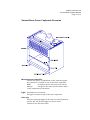
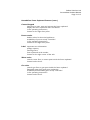
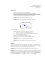
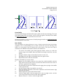
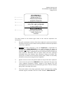
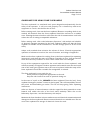
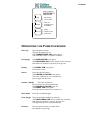
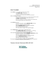
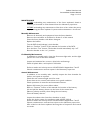
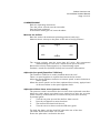
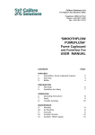
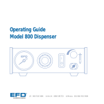
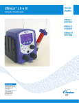
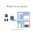
Calibre Solutions Ltd
145 Hepburn Rd, Waitakere 0602
Freephone: 0800 422 542
Phone: +64 9 813 1303
Fax: +64 9 813 1319
‘SMOOTHFLOW
STUDENT’
Fume Cupboard
and Fumeflow Fan
USER MANUAL
CONTENTS:
FEATURES
1.
2.
3.
Smoothflow Fume Cupboard Features
Sash Stop
Baffles
PREPARATION
4.
Warning!
5.
Guidelines for Safety
OPERATION
6.
Operating Instructions
7.
Faults
8.
Trouble shooting
MAINTENANCE
9.
Monthly
10.
Six Monthly
11.
Annually
DRAWINGS
COMMISSIONING & REPORTS
Calibre Solutions Ltd
Smoothflow Student Manual
Page 2 of 12
Smoothflow Fume Cupboard Features
Microprocessor controller
controls all aspects of operation via the control keypad
the controller is located on top of the fume cupboard
RCD*
protection device for the power sockets
battery*
energy for the mains power failure alarm
*refer maintenance instructions
Light illuminates the work area
the light is located on top of the fume cupboard
Sash stop
limits the opening height of the sash in normal operation
releases the sash to full height for service access
located on the left front pillar
Calibre Solutions Ltd
Smoothflow Student Manual
Page 3 of 12
Smoothflow Fume Cupboard Features (cont.)
Control keypad
input keys to start, stop and activate the fume cupboard
displays the fume cupboard status and alarms
*refer operating instructions
located on the right front pillar
Power outlet
double socket for electrical appliances
availability of power strictly controlled
*refer operating instructions
located on the right front pillar
Label important user information
spillage capacity
warning notice
fume cupboard serial number
located on the right corner of the sash
Water valve
controls water flow to water spout inside the fume cupboard
located under the sill
Gas valve
controls gas flow to gas spout inside the fume cupboard
flammable gases have push-turn mechanism
availability of flammable gases strictly controlled
*refer operating instructions
located under the sill
Calibre Solutions Ltd
Smoothflow Student Manual
Page 4 of 12
SASH STOP
The sash stop is located on the left front pillar
The sash stop limits the sash opening height to about 480mm.
With the opening restricted, less air flow is required to achieve fume capture.
The sash can be released for maximum opening for cleaning inside the fume
cupboard, or setting up equipment before the work starts.
ALWAYS lower the sash before commencing work
NEVER use the fume cupboard with the sash above the stop.
To release the sash:
Raise the sash until it reaches the upper stop position
1.
Insert a coin or key in the slot of the sash stop
2.
Twist the sash stop clockwise about a quarter turn and hold
3.
Raise the sash above the stop
Release the stop and withdraw the coin or key.
The stop will automatically reset when the sash is lowered
ALWAYS lower the sash before commencing work.
NEVER use the fume cupboard with the sash above the stop.
BAFFLES
There are two baffles in the fume cupboard. The baffles are easily removed to
facilitate cleaning of the entire fume chamber. This should be done as often as the
work requires, and at least monthly (refer maintenance instructions)
ALWAYS remove ALL chemicals and equipment from the fume cupboard.
ALWAYS wear personal protective equipment before handling baffles. Protective
equipment must be suitable for the chemicals used inside the fume cupboard. Refer
to Supervisor. Minimum requirements are overalls or coat with long sleeves;
suitable eye protection - glasses, goggles or mask; and suitable gloves.
Calibre Solutions Ltd
Smoothflow Student Manual
Page 5 of 12
Front Baffle
The front baffle hangs just behind the bypass grille and sash (see drawing). The clear
PVC baffle hangs from two hooks, one on each sash guide. Carefully lift the baffle
off both hooks at once to avoid fracture of a hook.
Replace the baffle by reverse action. Carefully hang the baffle on both hooks at once
to avoid fracture of a hook.
Rear Baffles
The rear baffles are sprung between a row of hooks inside the back of the fume
cupboard, and a corresponding row of hooks under the roof (see drawing). The
baffle is in two pieces, with a vertical join in the centre. The join cover strip is
attached to the RIGHT hand baffle. Remove this baffle first.
1.
2.
3.
4.
To remove the baffle, place both (gloved) hands, palms up, under the
bottom edge of the baffle. Raise the baffle and bring it forward, over the
hooks.
Bring the bottom edge of the baffle forward over the sill,
Disengage the top edge of the baffle from the upper hooks.
Repeat the action with the left baffle.
Replace the baffles by reverse action.
5.
Replace the left baffle (without cover strip) first. Hold the baffle with the
edge notch at the top left corner, and the slots offset towards the centre of
the fume cupboard (see diagram).
6.
Lift the baffle into the fume cupboard and engage the top edge of the baffle
in the upper hooks.
7.
Lift the bottom edge of the baffle over the sill,
8.
Carry the baffle to the back of the fume cupboard, and lift the bottom edge
onto the rear hooks.
9.
Check alignment in top and bottom hooks.
10.
Hold the right baffle with the edge notch at the top right corner, and the
cover strip towards the centre of the fume cupboard.
11.
Repeat actions 6 - 9 above with the right baffle.
Calibre Solutions Ltd
Smoothflow Student Manual
Page 6 of 12
1. ...................
2. ..................
3. ..................
4. ..................
5. ..................
WARNING
Spillage volume 20 L
Observe chemical limits
specified by Supervisor
No ignition sources in sump
ISOLATE FUME CUPBOARD
in case of spills or fire
Smoothflow
Fume Cupboard Serial No. XXX
Calibre Plastics Ltd
Auckland
The label located at the bottom right corner of the sash has important user
information.
1.
The spill containment volume of this fume cupboard is stated on the label.
The Supervisor may use this volume to limit quantities of chemicals permitted
in the fume cupboard.
2.
BEFORE the fume cupboard is used, the Supervisor is responsible for
carrying out a RISK ANALYSIS of the work. Consider the nature of
chemicals and processes to be used, to determine limiting quantities of
hazardous, flammable, oxidizing and corrosive substances allowed within the
fume cupboard. Remember that all liquids within the fume cupboard
(including water) may displace other substances during an incident. The
supervisor is to make a list of chemical quantity limits, which is to be readily
accessible to all persons using the fume cupboard.
3.
Ignition sources are not to be placed within the sump of the fume cupboard.
4.
In the event of a spill or fire, ISOLATE the fume cupboard. Press the (red)
“fume cupboard emergency isolator” button on the keypad. This will
immediately shut off the power and flammable gas outlets. The fan will keep
going. Refer operating instructions.
5.
The serial number of this fume cupboard may be requested when seeking
technical support, available Toll Free in New Zealand: 0800 422 542
Calibre Solutions Ltd
Smoothflow Student Manual
Page 7 of 12
GUIDELINES FOR USING FUME CUPBOARDS
The fume cupboard is a ventilated work space designed aerodynamically for the
safety of the operator. It will not work properly if it is cluttered up with excess
equipment or vessels, which affect the air flow.
Before starting work, clean out the fume cupboard. Remove everything which is not
needed. All chemicals from the fume cupboard should be removed to a suitable
store. Cleaning the internal surfaces will reduce the risk of contamination. It will also
reduce the risk of mixing incompatible substances.
Before starting work, refer to the Laboratory Supervisor’s risk analysis and schedule
of chemical quantities permitted in the fume cupboard. Make sure that the fume
cupboard is suitable for the intended use, and has enough space to do the work
safely.
Adopt work methods that minimise the release of fumes. Consider appropriate
quantities of substances involved, the rate of reaction, and design of apparatus.
Make sure the fume cupboard is working. Start up the fume cupboard (see operating
instructions), and check the status of all alarms, especially air flow. Look around the
room and close any windows or doors which could cause cross-draughts
Set up all the equipment required for the work inside the fume cupboard, with
sufficient quantity of reagents. Position apparatus and materials near the centre and
rear of the work space. Ignition sources are not to be placed within the sump of the
fume cupboard. Check that a suitable fire extinguisher is at hand.
The fume cupboard is now ready for use.
Wear protective equipment appropriate to the task.
Keep the sash lowered as much as practical during use.
In the event of a spill or fire, ISOLATE the fume cupboard. Press the (red) “fume
cupboard emergency isolator” button on the keypad. This will immediately shut off
the power and flammable gas outlets. The fan will keep going. Refer operating
instructions.
After use, dispose of waste substances with due regard for their potential to create
hazards, and within the rules of the local water authority. Refer also to the
Laboratory Supervisor, and the laboratory risk analysis.
Maintain the fume chamber in clean condition to avoid chemical contamination and
damage to the fume cupboard. Remove unused chemicals to a suitable store. Do not
use a fume cupboard for storage of chemicals. Lower the sash.
STUDENT
FUME CUPBOARD
EMERGENCY
ISOLATOR
RED
PRE-PURGE
POST-PURGE
AIRFLOW
GREEN
TEMPERATURE
SCRUBBER
READY
YELLOW
POWER & GAS
SPRAY BAR
OPERATING THE FUME CUPBOARD
Start up
Press the green button
The fan and light turn on
The TEMPERATURE LED will be green
The controller waits 7 seconds for airflow
Pre-purge
The AIRFLOW LED turns green
The PRE-PURGE LED will be amber for 50 seconds
then flash for another 10 seconds, then go out
Ready
The READY LED turns green
Four beeps sound
Active
Press the yellow button
The POWER & GAS LED turns green
The fume cupboard is now operational power & gas can be used
Isolate / Ready
Press the red button
Power & Gas turn off automatically
The POWER & GAS LED goes out
The READY LED turns green
Press the yellow button to re-activate, or
Shut down
Press the red button again
Post-purge
The fan and light continue to operate
The POST-PURGE LED will be amber for 4 minutes
then flash for another 1 minute, then go out.
The light and fan turn off automatically
Re-start
Press the green button to return from
post-purge to pre-purge
Calibre Solutions Ltd
Smoothflow Student Manual
Page 9 of 12
FAULT ALARMS
If the Power is cut, an alarm will sound a slow beep
The READY LED will flash red
Press the red button to mute the alarm
A long beep will sound as the controller shuts down.
When the Power is restored,
The fan will automatically turn on for 20 minutes then turn off;
An alarm will sound for 30 seconds, then turn off
The LED's will keep flashing.
Press the red button to reset the controller and stop the fan.
Press the green button for normal start up.
If the Airflow gets low
An alarm will sound , and the AIRFLOW LED will flash
Press the red button to mute the alarm
The fume cupboard will go into normal post-purge,
but the AIRFLOW LED will be red
Check out what caused the alarm.
Get it fixed before using the fume cupboard again.
If the Temperature inside the fume cupboard gets high
The TEMPERATURE LED will flash green as a warning
Turn down the heat inside the fume cupboard
If the temperature inside the fume cupboard gets higher
An alarm will sound , and the TEMPERATURE LED will flash
Press the red button to mute the alarm
The fume cupboard will go into normal post-purge,
but the TEMPERATURE LED will be red
Check out what caused the alarm.
Get it fixed before using the fume cupboard again.
The temperature sensor works even when the fume cupboard is turned off.
Press the red button to mute the alarm
TECHNICAL SUPPORT FREEPHONE 0800-422-542
Calibre Solutions Ltd
Smoothflow Student Manual
Page 10 of 12
TROUBLE SHOOTING
No power at power socket
Power is made available to the socket outlet only during “Active” status.
Refer operating instructions. After the pre-purge is complete and the Ready
LED lights up green, press the yellow button to activate the power outlet.
If the Power & Gas LED is lit up and there is still no power, check the RCD
breaker (the blue switch visible in the lid of the control box on top of the
fume cupboard).
When it is on, the switch lever is inclined toward the back of the fume
cupboard. If the switch will not latch on, there is an electrical fault in the
circuit. Call an electrician.
No gas at gas outlet
Gas is made available to the outlet only during “Active” status. Refer
operating instructions. After the pre-purge is complete and the Ready LED
lights up green, press the yellow button to activate the gas outlet.
If the Power & Gas LED is lit up and there is still no gas, check the RCD
breaker (the blue switch visible in the lid of the control box on top of the
fume cupboard).
When it is on, the switch lever is inclined toward the back of the fume
cupboard. If the switch will not latch on, there is an electrical fault in the
circuit. Call an electrician.
If the power socket is live but there is still no gas, the gas mains may be
isolated. Some laboratories have a master gas isolator.
Controller does not respond to keypad
If the control sequence has become corrupted, the controller needs to re-load
the program from memory, which happens automatically on power restore.
The mains isolator switch is visible in the lid of the control box on top of the
fume cupboard. The mains isolator is the switch on the left. When it is on,
the switch lever is inclined toward the back of the fume cupboard.
Turn off mains supply to the fume cupboard controller. Wait 5 seconds, then
turn the mains isolator on again. The processor will reboot, and signal a
power restore alarm (see operating instructions) Press the red button to reset
the controller, and start the fume cupboard as normal.
Calibre Solutions Ltd
Smoothflow Student Manual
Page 11 of 12
MAINTENANCE
BEFORE undertaking any maintenance of the fume cupboard, obtain a
summary of chemical or other hazards from the laboratory supervisor
BEFORE undertaking any maintenance of the duct or fan, isolate the power
supply and tag the fume cupboard “system under maintenance - do not use”
Monthly Maintenance
Remove all chemicals and equipment from the fume chamber.
Remove the rear baffles as described in Section 3 of this manual
Clean the fume chamber with dilute detergent
Replace the baffles
Test the RCD (earth leakage) circuit breaker
Refer to “Features” Section of this manual for location of the RCD.
Press the blue “Test” button. The breaker should immediately trip “off”
Reset the breaker to the “on” position.
Six Monthly Maintenance
In addition to monthly tasks, clean the fluorescent light tube, and the light
panel in the roof of the fume chamber.
Inspect and maintain fans, motors, drive belts and bearings
Check all plastic bolts, and replace if UV-brittle.
Perform smoke and velocity tests as AS/NZS 2243.8 Appendices F and E
Submit a maintenance and test report to the laboratory supervisor
Annual Maintenance
In addition to six monthly tasks, carefully inspect the fume chamber for
defects, and repair as required.
Check the sash counterweight cords for wear.
Ensure that service controls and outlets are in good condition.
Check operation of controller and automatic isolators.
Replace 9V battery for power failure alarm
Refer to “Features” Section of this manual for location of the battery.
Lift and pull the battery drawer on the front of the control box.
Observe polarity carefully when fitting the new battery.
Close the battery drawer.
Inspect the exhaust duct from fume chamber to stack
Assess the whole system for compliance with AS/NZS 2243.8
Perform smoke and velocity tests as AS/NZS 2243.8 Appendices F and E
Submit a maintenance, audit and test report to the laboratory supervisor.
Affix a label to the fume cupboard showing date of inspection and overall
test result.
Calibre Solutions Ltd
Smoothflow Student Manual
Page 12 of 12
COMMISSIONING
Refer the operating instructions
Turn the power on and reset the controller.
Start the fume cupboard.
If the airflow alarm goes off, mute the alarm.
Measure the airflow
Raise the sash to the maximum operating position (sash stop)
Measure the air velocity in the plane of the sash at six (6) positions
100+
100+
100mm
+
+
100mm
+100
+100
The average velocity must be more than 0.5 m/sec. We recommend
commissioning to 0.55 m/sec. Adjust the fan speed as below.
Record the velocity measurements in a commissioning report.
Conduct a smoke test (AS/NZS 2243.8) and record the observations.
Adjust the fan speed (Fumeflow T250 fan):
The Fumeflow T250 fan is usually installed above the roof.
There is a speed regulator in a plastic box beside the fan motor.
Adjust the speed regulator clockwise to increase speed, or anti-clockwise to
reduce speed.
When the correct speed is set for fume cupboard face velocity, apply a bead
of silicone sealant to the speed regulator shaft
Adjust the airflow alarm sensor (pressure switch):
The pressure switch is mounted in the lid of the fume cupboard controller.
Adjust the white plastic cross-head screw clockwise to raise the set point
(more sensitive) or anticlockwise to reduce the set point (less sensitive).
A practical guide:
1.
Turn the set point up until the Airflow alarm sounds
2.
Press the red button to mute the alarm.
3.
The Airflow LED should still be red.
4.
Turn the set-screw down until the LED turns green.
To check the alarm, pull the clear PVC pilot tube out of the duct.
The alarm should sound after 2-3 seconds.
Ensure the pilot tube is re-fitted in the duct.