1
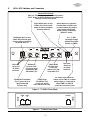
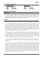
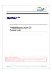
TC3005(LED/ELED/LASER)
165Mbps Fiber Optic Mode Converter/Repeater
TC3005
(LED/ELED/LASER)
User's Manual
Rev. 3.0
User's Manual
1.
Description
The TC3005 gives users the ability to convert Multimode fiber optic signals to Single Mode format for data
transmission (and vice-versa). These conversions can benefit users by extending transmission distances
and/or enabling dissimilar fiber optic devices to be used with different fiber types. The optic receiver detects
the incoming optical signal and regenerates it for transmission through the second optic transmitter. The
TC3005 is available in multiple configurations depending on your communication requirements. When both
sides have the same wavelength, the TC3005 works like an optical signal repeater.
2.
Data Rates
165Mbps*
*Contact factory for higher data rates.
3.
Optical Specifications
Transmitter:
LED; typical Launch Power:
ELED; typical Launch Power:
LASER; typical Launch Power:
-16 dBm* (850nm/1310nm, Multimode @62.5/125µm)
-16 dBm* (1310nm/1550nm, Single Mode @9/125µm)
-6 dBm* (1310nm/1550nm, Single Mode @9/125µm)
Receiver:
PIN DIODE; typical Sensitivity:
-33 dBm* (850nm/1310nm, Multimode @62.5/125µm)
-33 dBm* (1310nm/1550nm, Single Mode @9/125µm)
-36 dBm* (1310nm/1550nm, Single Mode @9/125µm)
Loss Budget:
LED; 850nm/1310nm, MM @62.5/125µm
ELED; 1310nm/1550nm, SM @9/125µm
LASER; 1310nm/1550nm, SM @9/125µm
Distance:
850nm, Multimode @62.5/125µm
1310nm, Multimode @62.5/125µm
1310nm, Single Mode @9/125µm
1550nm, Single Mode @9/125µm
Wavelength:
Note: Any two wavelength combinations are available on each unit.
16 dB
16 dB
25 dB
up to 3km*
up to 4km*
up to 40km*
up to 110km*
850nm Multimode (LED)
1310nm Multimode (LED)
1310nm Single Mode (ELED/LASER)
1550nm Single Mode (ELED/LASER)
Connector:
ST, FC, or SC
*Launch power, sensitivity and distance are listed for reference only. These numbers may vary. Contact
factory for higher loss budgets.
4.
Power Requirements
A. The TC3005 consumes very low power. The connector is a terminal block with polarity indicated on the
rear panel of the unit (see Figure 2). The input voltage is typically 12 VDC and current is @600mA. The
unit can be ordered with optional power options: 24 VDC@300mA, 48 VDC@150mA, or 115/230 VAC
with an external power adapter.
B . Should an external power adapter need to be replaced, use one that matches the above specifications.
You may order it from TC Communications.
C. There are two pairs of terminal block connectors on the rear panel (labeled "PWR A" and "PWR B").
Only one pair is required to power the unit. If both pairs are connected, the built-in power redundancy
feature will be utilized. When this feature is utilized, both "A" and "B" share the load. If one power source
fails, the other will assume the full load.
© COPYRIGHT 1992-2004. ALL RIGHTS RESERVED.
TC Communications, Inc. 17575 Cartwright Road - Irvine, CA 92614
Tel: (949) 852-1972 Fax: (949) 852-1948 Web Site: www.tccomm.com Email: [email protected]
−1−
TC3005
(LED/ELED/LASER)
User's Manual
Rev. 3.0
5.
LEDs, DIP Switches and Connectors
DIP Switch Functions
SW1,2,3 - Not Used; reserved for future functions.
SW4 - Down (or Right) Disables the audio buzzer
and Dry Contact Relay Alarm.
Alarm: When lit, it indicates
a broken fiber condition and
closure of alarm dry contact
relay (buzzer will sound).
Buzzer can be disabled by
"DISALM” switch.
Single Mode optic receive
status: SM received optic
power is above sensitivity
threshold when lit.
Multimode optic receive
status: MM received optic
power is above sensitivity
threshold when lit.
Vcc: +5 VDC
operating voltage
derived from either
PWR A or PWR B
MM
Tx
SM
Rx
MM RX
FIBER OPTIC
MODE CONVERTER
ON
1
2
3
Tx
Rx
SM RX
4
ALM
A
B PWR
Vcc
TCCOMM.COM
Made in U.S.A.
Single Mode
Receiver (Rx):
Connect to
remote unit's SM
Transmitter (Tx).
Multimode
Receiver (Rx):
Connect to local
equipment's MM
Transmitter (Tx).
Not Used.
Reserved
for future
functions.
Multimode Transmitter
(Tx): Connect to local
equipment's MM
Receiver (Rx).
Single Mode
Transmitter (Tx):
Connect to remote
unit's SM Receiver (Rx).
Not Used.
Reserved
for future
functions.
DC Power Input Status for
PWR A and/or PWR B: Lit when
power supply is connected to
either PWR A or PWR B
connector on the rear panel
Figure 1. TC3005's Front Panel
PWR
A
PWR
B
ALARM
+ + (12-14 VDC) @600mA
Figure 2. TC3005's Rear Panel
−2−
6.
TC3005
(LED/ELED/LASER)
User's Manual
Rev. 3.0
Dry Contact Relay Alarm
A terminal block connector on the rear panel (labeled
"ALARM") provides for the dry contact relay alarm (see Figure
2). Normally in the OPEN position, the loss of either optic signal
will trigger an alarm condition and force the switch to the
CLOSED position. This relay can be used in conjunction with
an external device to monitor the condition of the fiber optic
links. Note: If SW4 (DISALM) on the front panel is in the Down
position, the audio buzzer will not sound and the dry contact
relay will not activate.
7.
Dry Contact Relay
Alarm Switch
To remote alarm status indicator
Reply switch specifications
Max switch voltage: 100VDC
Switch current: 0.5Amp
Max carry current: 1.2Amp
Contact resistance: 0.2Ohm
Installation
TC3005
TC3005
Fiber Optic Mode Converter
Fiber Optic Mode Converter
MM Rx
SM Tx
MM Tx
SM Rx
SM Tx
MM Rx
SM Rx
MM Tx
Single Mode
fiber optic cable
Multimode
fiber optic
cable
Multimode
fiber optic
cable
Tx Rx
Multimode
850nm/1300nm
TRANSCEIVER
Rx Tx
Multimode
850nm/1300nm
TRANSCEIVER
Figure 3. Installation Diagram for Dual TC3005 Application
TC3005
Fiber Optic Mode Converter
MM Rx
SM Tx
MM Tx
SM Rx
Multimode
fiber optic
cable
Single Mode
fiber optic
cable
Tx Rx
Multimode
850nm/1300nm
TRANSCEIVER
Tx Rx
Single Mode
1300nm/1550nm
TRANSCEIVER
Figure 4. Installation Diagram for Single TC3005 Application
−3−
TC3005
(LED/ELED/LASER)
User's Manual
Rev. 3.0
8.
Troubleshooting
Typically, most problems encountered with the TC3005 are related to optic receiver overdrive. The
maximum optic power that can be received without distortion is referred to as the optic receiver's "saturation
level." When the incoming optic power is greater than the saturation level of the receiver, optic "overdrive"
can occur.
The TC3005's optic receivers have a typical saturation level of -14 dBm. If the user's equipment's launch
power is higher than -14dBm (i.e. -13dBm or greater) and the fiber run is very short and has low signal loss,
it is likely to overdrive the TC3005's Multimode receiver. The consequences of overdrive can be high error
rates or the device's failure to recognize the incoming optic signal at all.
The TC3005 has been adjusted at the factory so that the Single Mode transmitter will not overdrive the Single
Mode receiver even when short cables are used to connect them; hence, the overdrive condition happens
most frequently at the Multimode receiver optic.
If you suspect the Multimode receiver has an optic overdrive condition, a simple test will help verify it. At
the receiving optic in question, simply disconnect the optic connector and back it out of the receptacle (about
1/8 of an inch), creating a gap between the fiber connector and the receiver. Verify that the equipment is
still in "sync" with the optic signal and that the overdrive condition has been corrected. To resolve the
overdrive condition permanently, insert a 5dB or 10dB in-line attenuator into the problem link. In-line
attenuators can be purchased from Metrotek* at (914) 347-4112. The part numbers are:
Description:
Part Number:
ST@5dB
68-JJ-7-0513
ST@10dB
68-JJ-7-1013
FC@5dB
68-FF-0513
FC@10dB
68-FF-1013
The following diagram illustrates a TC3005 Mode Converter used to convert a 1300nm Single Mode optical
signal from an OC3 (155 Mbps) ATM SWITCH into a 1300nm Multimode optic signal to be received by the
HP7000.* In the reverse direction, the HP7000's Multimode optic signal is converted to Single Mode format
to be received by the OC3 ATM SWITCH. In-line attenuators are used to correct optic overdrive conditions
that exist on either side of the TC3005.
launch power:
-10 dBm
Receiving power:
-20 dBm
3005
1300nm SM
Tx
Rx
ATTN
10 dB
Rx
SM
Tx
MM
1300nm MM
Tx
Rx
ATTN
15 dB
OC3
ATM
SWITCH
Rx
1300nm MM Tx
HP7000
receiving power:
-22 dBm
launch power:
-7 dBm
Note: Launch power measurements are taken at 155Mbps and may vary due to the actual signal's duty cycle.
Figure 5. In-line Attenuator Placement Diagram
*HP (Hewlett Packard) and Metrotek are corporate names and are not affiliated with TC Communications, Inc.
−4−
TC3005
(LED/ELED/LASER)
User's Manual
Rev. 3.0
9.
Physical Characteristics
Rack Mountable Card
Height:
7.0" (17.7 cm)
Width:
1.2" (3.1 cm)
Depth:
5.8" (14.8 cm)
Weight:
8.5 oz. (188 gm)
Stand Alone Unit
Height:
1.4" (3.5 cm)
Width:
7.1" (18 cm)
Depth:
6.6" (16.6 cm)
Weight:
1.5 lbs. (512 gm)
10. Return Policy & Warranty
Return Policy
To return a product, you must first obtain a Return Material Authorization number from the Customer
Service Department. If the product’s warranty has expired, you will need to provide a purchase order to
authorize the repair. When returning a product for a suspected failure, please provide a description of the
problem and any results of diagnostic tests that have been conducted.
Warranty
Damages by lightning or power surges are not covered under this warranty.
All products manufactured by TC Communications, Inc. come with a five year (beginning 1-1-02)
warranty. TC Communications, Inc. warrants to the Buyer that all goods sold will perform in accordance
with the applicable data sheets, drawings or written specifications. It also warrants that, at the time of sale,
the goods will be free from defects in material or workmanship. This warranty shall apply for a period of
five years from the date of shipment, unless goods have been subject to misuse, neglect, altered or destroyed
serial number labels, accidents (damages caused in whole or in part to accident, lightning, power surge, floods,
fires, earthquakes, natural disasters, or Acts of God.), improper installation or maintenance, or alteration or
repair by anyone other than Seller or its authorized representative.
Buyer should notify TC Communications, Inc. promptly in writing of any claim based upon warranty, and
TC Communications, Inc., at its option, may first inspect such goods at the premises of the Buyer, or may
give written authorization to Buyer to return the goods to TC Communications, Inc., transportation charges
prepaid, for examination by TC Communications, Inc. Buyer shall bear the risk of loss until all goods
authorized to be returned are delivered to TC Communications, Inc. TC Communications, Inc. shall not be
liable for any inspection, packing or labor costs in connection with the return of goods.
In the event that TC Communications, Inc. breaches its obligation of warranty, the sole and exclusive
remedy of the Buyer is limited to replacement, repair or credit of the purchase price, at TC Communications,
Inc.’s option.
To return a product, you must first obtain a Return Material Authorization (RMA) number and RMA form
from the Customer Service Department. If the product’s warranty has expired, you will need to provide a
purchase order to authorize the repair. When returning a product for a suspected failure, please fill out RMA
form provided with a description of the problem(s) and any results of diagnostic tests that have been
conducted. The shipping expense to TC Communications should be prepaid. The product should be properly
packaged and insured. After the product is repaired, TC Communications will ship the product back to the
shipper at TC's cost to U.S. domestic destinations. (Foreign customers are responsible for all shipping costs,
duties and taxes [both ways]. We will reject any packages with airway bill indicating TC communications
is responsible for Duties and Taxes. To avoid Customs Duties and Taxes, please include proper documents
indicating the product(s) are returned for repair/retest).
−5−