1
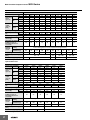
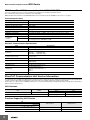
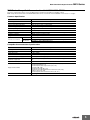
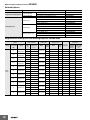
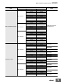
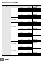
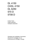
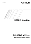
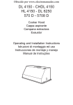
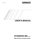
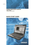
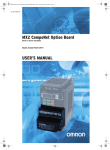
Multi-function Compact Inverter
MX2-Series
With Machine Automation Mentality
• Current vector Control.
• High Starting torque: 200% at 0.5 Hz.
• Double rating VT 120%/1 min and CT 150% /1 min.
• Speed range up to 1,000 Hz.
• Positioning functionality.
• Safety function *1 EN ISO13849-1:2008 (Cat.3/PLd)
IEC60204-1 Stop Category 0
• Fieldbus communications with optional unit *2:
EtherCAT, CompoNet and DeviceNet *3
• Modbus communications.
*1 When optional communication unit is mounted onto the MX2, the inverter will not
conform to the safety standards.
*2 Optional communication unit can be used with the inverter 3G3MX2 of unit version
1.1 or higher.
*3 DeviceNet communication unit will be available soon.
Performance Specifications
Inverter 3G3MX2
3-phase 200 V Class
Function name
Model name (3G3MX2-)
Applicable kW
motor
capacity
HP
Rated
output
capacity
[kVA]
200 V
240 V
3-phase 200 V
A2001
A2002
A2004
A2007
A2015
A2022
A2037
A2055
A2075
A2110
CT
0.1
0.2
0.4
0.75
1.5
2.2
3.7
5.5
7.5
11
15
VT
0.2
0.4
0.75
1.1
2.2
3.0
5.5
7.5
11
15
18.5
CT
1/8
1/4
1/2
1
2
3
5
7 1/2
10
15
20
VT
1/4
1/2
1
1 1/2
3
4
7 1/2
10
15
20
25
CT
0.2
0.5
1.0
1.7
2.7
3.8
6.0
8.6
11.4
16.2
20.7
VT
0.4
0.6
1.2
2.0
3.3
4.1
6.7
10.3
13.8
19.3
23.9
CT
0.3
0.6
1.2
2.0
3.3
4.5
7.2
10.3
13.7
19.5
24.9
VT
0.4
0.7
1.4
2.4
3.9
4.9
8.1
12.4
16.6
23.2
28.6
Rated input voltage
Rated input current
[A]
3-phase 200 V - 15% to 240 V + 10%, 50/60 Hz ± 5%
CT
1.0
1.6
3.3
6.0
9.0
12.7
20.5
30.8
39.6
57.1
62.6
VT
1.2
1.9
3.9
7.2
10.8
13.9
23.0
37.0
48.0
68.0
72.0
Rated output voltage
Rated output
current [A]
3-phase 200 to 240 V (The output cannot exceed the incoming voltage).
CT
1.0
1.6
3.0
5.0
8.0
11.0
17.5
25.0
33.0
47.0
60.0
VT
1.2
1.9
3.5
6.0
9.6
12.0
19.6
30.0
40.0
56.0
69.0
50
50
50
50
50
20
20
20
20
10
10
Short-time deceleration
braking torque (%)
(Discharge Resistor not
connected)
Braking
Resistor
circuit *
A2150
Regenerative
braking
Min. connectable
resistance [Ω]
Weight [kg]
Built-in Braking Resistor circuit (separate Discharge Resistor)
100
100
100
50
50
35
35
20
17
17
10
1.0
1.0
1.1
1.2
1.6
1.8
2.0
3.3
3.4
5.1
7.4
180 ×
296
220 ×
350
Dimensions (width × height)
[mm]
Dimensions (depth) [mm]
68 × 128
109
122.5
145.5
108 × 128
140 ×
128
140 × 260
170.5
170.5
155
175
* The BRD usage is 10%.
Sysmac is a trademark or registered trademark of OMRON Corporation in Japan and other countries for OMRON factory automation products.
Windows is registered trademarks of Microsoft Corporation in the USA and other countries.
EtherCAT® is a registered trademark and patented technology, licensed by Beckhoff Automation GmbH, Germany.
Other company names and product names in this document are the trademarks or registered trademarks of their respective companies.
1
Multi-function Compact Inverter
MX2-Series
3-phase 400 V Class
Function name
Model name (3G3MX2-)
Applicable kW
motor
capacity
HP
Rated
output
capacity
[kVA]
380 V
480 V
3-phase 400 V
A4004
A4007
A4015
A4022
A4030
A4040
A4055
A4075
A4110
CT
0.4
0.75
1.5
2.2
3.0
4.0
5.5
7.5
11
15
VT
0.75
1.5
2.2
3.0
4.0
5.5
7.5
11
15
18.5
CT
1/2
1
2
3
4
5
7 1/2
10
15
20
VT
1
2
3
4
5
7 1/2
10
15
20
25
CT
1.1
2.2
3.1
3.6
4.7
6.0
9.7
11.8
15.7
20.4
VT
1.3
2.6
3.5
4.5
5.7
7.3
11.5
15.1
20.4
25.0
CT
1.4
2.8
3.9
4.5
5.9
7.6
12.3
14.9
19.9
25.7
VT
1.7
3.4
4.4
5.7
7.3
9.2
14.5
19.1
25.7
31.5
Rated input voltage
Rated input current
[A]
3-phase 380 V - 15% to 480 V + 10%, 50/60 Hz ± 5%
CT
1.8
3.6
5.2
6.5
7.7
11.0
16.9
18.8
29.4
35.9
VT
2.1
4.3
5.9
8.1
9.4
13.3
20.0
24.0
38.0
44.0
Rated output voltage
Rated output
current [A]
3-phase 380 to 480 V (The output cannot exceed the incoming voltage).
CT
1.8
3.4
4.8
5.5
7.2
9.2
14.8
18.0
24.0
31.0
VT
2.1
4.1
5.4
6.9
8.8
11.1
17.5
23.0
31.0
38.0
50
50
50
20
20
20
20
20
10
10
Short-time deceleration
braking torque (%)
(Discharge Resistor not
connected)
Braking
Resistor
circuit *
Regenerative
braking
Min. connectable
resistance [Ω]
Weight [kg]
Built-in Braking Resistor circuit (separate Discharge Resistor)
180
180
180
100
100
1.5
1.6
1.8
1.9
1.9
Dimensions (width × height)
[mm]
Dimensions (depth) [mm]
108 × 128
143.5
170.5
100
70
70
70
35
2.1
3.5
3.5
4.7
5.2
140 ×
128
140 × 260
180 × 296
170.5
155
175
* The BRD usage is 10%.
1-phase 200 V Class
Function name
Model name (3G3MX2-)
Applicable kW
motor
capacity
HP
Rated
output
capacity
[kVA]
200 V
240 V
1-phase 200 V
AB001
AB002
AB004
AB007
AB015
AB022
CT
0.1
0.2
0.4
0.75
1.5
2.2
VT
0.2
0.4
0.55
1.1
2.2
3.0
CT
1/8
1/4
1/2
1
2
3
VT
1/4
1/2
3/4
1 1/2
3
4
CT
0.2
0.5
1.0
1.7
2.7
3.8
VT
0.4
0.6
1.2
2.0
3.3
4.1
CT
0.3
0.6
1.2
2.0
3.3
4.5
VT
0.4
0.7
1.4
2.4
3.9
4.9
Rated input voltage
Rated input current
[A]
1-phase 200 V - 15% to 240 V + 10%, 50/60 Hz ± 5%
CT
1.3
3.0
6.3
11.5
16.8
22.0
VT
2.0
3.6
7.3
13.8
20.2
24.0
Rated output voltage
Rated output
current [A]
3-phase 200 to 240 V (The output cannot exceed the incoming voltage).
CT
1.0
1.6
3.0
5.0
8.0
11.0
VT
1.2
1.9
3.5
6.0
9.6
12.0
50
50
50
50
50
20
Short-time deceleration
braking torque (%)
(Discharge Resistor not
connected)
Braking
Resistor
circuit *
Regenerative
braking
Min. connectable
resistance [Ω]
Weight [kg]
Built-in Braking Resistor circuit (separate Discharge Resistor)
100
100
100
50
50
35
1.0
1.0
1.1
1.6
1.8
1.8
Dimensions (width × height)
[mm]
Dimensions (depth) [mm]
* The BRD usage is 10%.
2
A4150
68 × 128
109
108 × 128
122.5
170.5
Multi-function Compact Inverter
MX2-Series
Function Specifications
Control
Function name
Enclosure ratings *1
Control method
Output frequency range *2
Frequency precision *3
Frequency setting resolution
Voltage/Frequency
characteristics
Overload current rating
Instantaneous overcurrent
protection
Acceleration/Deceleration time
Carrier frequency adjustment range
Starting torque
Multi-function input
Analog input
Pulse input
Multi-function output
2 points (P1/EDM, P2; selectable from 43 functions)
Relay output
1 point (1c contact: MC, MA, MB; selectable from 43 functions)
Protective functions
Communications Output signal
Input signal
Frequency settings
RUN/STOP command
Analog output (Frequency monitor) 1 point (AM terminal: Voltage 10 bits/0 to 10 V) (Frequency, current selectable)
Pulse output
1 point (MP terminal: 32 kHz max., 0 to 10 V)
RS-422
RJ45 connector (for Digital Operator)
RS-485
Control circuit terminal block, Modbus communication (Modbus-RTU)
USB
USB1.1, mini-B connector
Other functions
General specifications
200% of the value of heavy load rating (CT)
0.01 to 3600 s (linear/curve selection), acceleration/deceleration 2 setting available
2 to 15 kHz (with derating)
200%/0.5 Hz (sensorless vector control)
Starts at a frequency lower than that in deceleration via the STOP command, at a value set lower than
that during operation, or via an external input. (Level and time settable).
Overcurrent, overvoltage, undervoltage, electronic thermal, temperature error, ground fault overcurrent
at power-on status, rush current prevention circuit, overload limit, incoming overvoltage, external trip,
memory error, CPU error, USP error, communication error, overvoltage suppression during
deceleration, protection upon momentary power outage, emergency cutoff, etc.
Digital Operator
External analog input signal: 0 to 10 VDC/4 to 20 mA, Modbus communication (Modbus-RTU)
Digital Operator
External digital input signal (3-wire input supported), Modbus communication (Modbus-RTU)
7 points (Selectable from 59 functions)
2 points (Voltage FV terminal: 10 bits/0 to 10 V, Current FI terminal: 10 bits/4 to 20 mA)
1 point (RP terminal: 32 kHz max., 5 to 24 VDC)
External DC injection braking
AVR function, V/f characteristics switching, upper/lower limit, 16-step speeds, starting frequency
adjustment, jogging operation, carrier frequency adjustment, PID control, frequency jump, analog gain/
bias adjustment, S shape acceleration/deceleration, electronic thermal characteristics, level adjustment,
restart function, torque boost function, fault monitor, soft lock function, frequency conversion display,
USP function, motor 2 control function, UP/DWN, overcurrent control function, etc.
Ambient temperature
-10 to 50°C (However, derating is required).
Ambient storage temperature
-20°C to 65°C (short-time temperature during transport)
Humidity
20% to 90% RH (with no condensation)
Vibration
5.9 m/s2 (0.6G), 10 to 55 Hz
Location
Options
International standard
Specifications
Open type (IP20)
Phase-to-phase sinusoidal modulation PWM
0.10 to 400 Hz (or 1,000 Hz in the high-frequency mode; restrictions apply)
Digital command: ±0.01% of the max. frequency, Analog command: ±0.2% of the max. frequency (25°C±10°C)
Digital setting: 0.01 Hz, Analog setting: One-thousandth of the maximum frequency
V/f characteristics (constant/reduced torque)
Sensorless vector control, V/f control with speed feedback
Heavy load rating (CT): 150%/60 s
Light load rating (VT): 120%/60 s
EMC directive
Low voltage
EC
directive
directive
Machinery
directives
UL/cUL
At a maximum altitude of 1,000 m; indoors (without corrosive gases or dust)
DC reactor, AC reactor, radio noise filter, input noise filter, output noise filter, regenerative braking unit,
Braking Resistor, EMC noise filter, etc.
EN61800-3: 2004
EN61800-5-1: 2003
IEC60204-1 Stop Category 0, EN IEC61800-5-2 (STO), EN ISO13849-1: 2008 (PLd), ISO13849-1: 2006
(PLd)
UL508C
Note: 1. The applicable motor is a 3-phase standard motor. For using any other type, be sure that the rated current does not exceed that of the Inverter.
2. Output voltage decreases according to the level of the power supply voltage.
3. The braking torque at the time of capacitor feedback is an average deceleration torque at the shortest deceleration (when it stops from
50 Hz). It is not a continuous regeneration torque. Also, the average deceleration torque varies depending on the motor loss. The value
is reduced in operation over 50 Hz.
*1 Protection method complies with JEM 1030.
*2 To operate the motor at over 50/60 Hz, contact the motor manufacturer to find out the maximum allowable speed of revolution.
*3 For the stable control of the motor, the output frequency may exceed the maximum frequency set in A004 (A204) by 2 Hz max.
3
Multi-function Compact Inverter
MX2-Series
MX2-Series EtherCAT Communication Unit 3G3AX-MX2-ECT
This is the communication unit to connect the Multi-function Compact Inverter MX2 to EtherCAT network.
This communication unit passed the conformance test of EtherCAT.
Note: EtherCAT Communication Unit 3G3AX-MX2-ECT can be used with the inverter 3G3MX2 of unit version 1.1 or higher.
Common Specifications
Item
Specifications
Power supply
Supplied from the inverter
Protective structure
Open type (IP20)
Ambient operating temperature
−10 to +50°C
Ambient storage temperature
−20 to +65°C
Ambient operating humidity
20% to 90% RH (with no condensation)
Vibration resistance
5.9 m/s2 (0.6 G), 10 to 55 Hz
Application environment
At a maximum altitude of 1,000 m; indoors (without corrosive gases or dust)
Weight
100 g max.
International
standard
UL/cUL
UL508C
EC directive
EMC Directive
:EN61800-3: 2004
Low Voltage Directive :EN61800-5-1: 2003
EtherCAT Communications Specifications
Item
Specifications
Communications standard
IEC 61158 Type12, IEC 61800-7 CiA 402 drive profile
Physical layer
100BASE-TX (IEEE802.3)
Connector
RJ45 × 2 (shielded type)
ECAT IN
: EtherCAT input
ECAT OUT : EtherCAT output
Communications media
Category 5 or higher (cable with double, aluminum tape and braided shielding) is
recommended.
Communications distance
Distance between nodes: 100 m max.
Process data
Fixed PDO mapping
PDO mapping
Mailbox (CoE)
Emergency messages, SDO requests, SDO responses, and SDO information
Distributed clock
FreeRun mode (asynchronous)
LED display
L/A IN (Link/Activity IN) × 1
L/A OUT (Link/Activity OUT) × 1
RUN × 1
ERR × 1
CiA402 drive profile
Velocity mode
EtherCAT Communication Unit Version Information
As a Sysmac Device, the MX2-series Multi-function Compact Inverter is designed to provide optimal functionality and enhanced operability when
used in conjunction with a Machine Automation Control such as NJ series and the automation software Sysmac Studio.
Sysmac Device is a generic term for OMRON control devices such as an EtherCAT Slave, designed with unified communications specifications
and user interface specifications.
Unit Versions
Unit
Unit version
Model
EtherCAT Communication Unit for MX2-Series
Ver.1.0
3G3AX-MX2-ECT
Compatible Sysmac Studio version
Ver1.1
Supported
Supported
Version1.00 or higher*
Version1.00 or higher
* The function that was enhanced by the upgrade for Unit version1.1 can not be used. For detail, refer to "Function Support by Unit Version".
Function Support by Unit Version
Unit
Model
Unit version
Unit version 1.0
Unit version 1.1
Item
4
Store-function of back-up number of parameters
Not supported
Supported
Initializing function as parameters.
Not supported
Supported
Multi-function Compact Inverter
MX2-Series
MX2-Series CompoNet Communication Unit 3G3AX-MX2-CRT-E
This is the communication unit to connect the Multi-function Compact Inverter MX2 to CompoNet network.
Note: CompoNet Communication Unit 3G3AX-MX2-CRT-E can be used with the inverter 3G3MX2 of unit version 1.1 or higher.
Common Specification
Item
Specification
Power supply
Supplied from the inverter
Protective structure
IP20
Ambient operating temperature
− 10 to 55 °C (no icing or condensation)
Ambient storage temperature
− 20 to 65 °C (no icing or condensation)
Ambient operating humidity
20 to 90%RH
Vibration resistance
5.9m/s2 (0.6G), 10 to 55Hz
Application environment
At a maximum altitude of 1,000 m; indoors (without corrosive gases or dust)
Insulation resistance
500VAC (between isolated circuits)
Weight
Approx. 170g
UL/cUL
International standard
EC directive
UL508
EN61800-3: 2004 (2004/108/EC) Second environment, Category C3
EN61800-5-1: 2007 (2006/95/EC) SELV
CompoNet Communications Specifications
Item
Specification
Slave type
Word Slave Unit (Mixed)
Certification
CompoNet Conformance Tested
CompoNet Profile
AC Drive (0x02)
Node Address
0 to 63, set with inverter parameter P190 or the rotary switches.
Communication power supply
- (External power not required)
Baud rates supported
4 Mbps, 3 Mbps, 1.5 Mbps, 93.75 kbps. Automatically detecting baud rate of Master
Unit
Default Connection path
Supported, set with inverter parameter P046
Supported Assemblies
Basic Remote IO (Output assembly 20, Input assembly 70)
Extended Speed IO (21, 71)
Extended Speed and Torque Control (123, 173)
Special IO (100, 150)
Extended Control IO (101, 151)
Extended Control IO and Multi function IO monitor (101, 153)
Flexible Format (139, 159)
Extended Speed and Acceleration Control (110, 111)
EDS file
Depending on the MX2 inverter model
5
Multi-function Compact Inverter
MX2-Series
MX2-Series DeviceNet Communication Unit 3G3AX-MX2-DRT-E
This is the communication unit to connect the Multi-function Compact Inverter MX2 to DeviceNet network.
Note: DeviceNet Communication Unit 3G3AX-MX2-DRT-E can be used with the inverter 3G3MX2 of unit version 1.1 or higher.
Common Specification
Item
Specification
Power supply
Supplied from the inverter
Protective structure
IP20
Ambient operating temperature
− 10 to 55 °C (no icing or condensation)
Ambient storage temperature
− 20 to 65 °C( no icing or condensation)
Ambient operating humidity
20 to 90%RH
Vibration resistance
5.9m/s2 (0.6G), 10 to 55Hz
Application environment
At a maximum altitude of 1,000 m; indoors (without corrosive gases or dust)
Insulation resistance
500VAC (between isolated circuits)
Weight
Approx. 170g
UL/cUL
International standard
EC directive
UL508
EN61800-3: 2004 (2004/108/EC) Second environment, Category C3
EN61800-5-1: 2007 (2006/95/EC) SELV
DeviceNet Communications Specifications
Item
6
Specification
Certification
DeviceNet Conformance Tested
DeviceNet Profile
AC Drive (0x02)
Supported connections
Remote I/O: Master-Slave connection
Poll
Bit-Strobe
COS
Cyclic
Explicit Messages
Conform to DeviceNet specifications
Communication power supply
11 to 25VDC (MAX 50 mA, type 20 mA)
Unit device address range
MAC ID 0 to 63, set with inverter parameter P192
Baud rates supported
4 Mbps, 3 Mbps, 1.5 Mbps, 93.75 kbps. Automatically detecting baud rate of Master
Unit
Default Connection path
Supported, set with inverter parameter P046
Supported Assemblies
Basic Remote IO (Output assembly 20, Input assembly 70)
Extended Speed IO (21, 71)
Extended Speed and Torque Control (123, 173)
Special IO (100, 150)
Extended Control IO (101, 151)
Extended Control IO and Multi function IO monitor (101, 153)
Flexible Format (139, 159)
Extended Speed and Acceleration Control (110, 111)
In case the DeviceNet master is configured using user allocation, only the input /
output pairs can be configured.
EDS file
Depending on the MX2 Inverter model
Multi-function Compact Inverter
MX2-Series
Components and Functions
Inverter 3G3MX2
Modbus-RTU Termination resistor selector switch
OFF
(Factory default)
Safety function selector switch
Disable
(Factory default)
ON
Enable
USB connector (mini-B)
Connector for optional board
Connector for Digital Operator (RJ45)
EDM function selector switch
P1 terminal
(Factory default)
Multi-function contact terminal block
EDM output
Control circuit terminal block A
Control circuit terminal block B
CHARGE indicator
Main circuit terminal block
Name
Function
Modbus-RTU Termination resistor
selector switch
Use this Terminal Resistor selector switch for RS-485 terminals on the control circuit terminal block. When this switch is turned
ON, the internal 200 Ω Resistor is connected.
Safety function selector switch
Turn this switch ON when using the safety function. Turn OFF the power before turning this switch ON/OFF. For details, refer to
USER’S MANUAL (Cat.No.I570).
EDM function selector switch
Turn this switch ON when using the EDM output of the safety function. Turn OFF the power before turning this switch ON/
OFF.For details, refer to USER’S MANUAL (Cat.No.I570).
USB connector
Use this mini-B USB connector to connect a PC.
Even when the Inverter is being operated by a PC, etc., via USB connection, it can still be operated using the Digital Operator.
Connector for Digital Operator
Use this connector to connect the Digital Operator.
Connector for optional board
Use this connector to mount the optional board. (Communications Units and other options can be connected.)
Control circuit terminal blocks A
and B
These terminal blocks are used to connect various digital/analog input and output signals for inverter control, etc.
Multi-function contact terminal block
Use this SPDT contact terminal block for relay outputs.
Main circuit terminal block
Use this terminal block to connect an output to the motor and Braking Resistor, etc.
Also, use this terminal block to connect the inverter to the main power supply.
CHARGE indicator
(Charge indicator LED)
This LED indicator is lit if the DC voltage of the main circuit (between terminals P/+2 and N/-) remains approx. 45 V or above
after the power has been cut off. Before wiring, etc. confirm that the Charge LED indicator is turned OFF.
Note: This illustration shows the terminal block with the front cover removed.
EtherCAT Communication Unit 3G3AX-MX2-ECT
Status indicator
(L/A IN, L/A OUT,
RUN, ERR)
Rotary switches
for node address
setting (× 10, × 1)
FG cable
Communications connector
(IN, OUT)
7
Multi-function Compact Inverter
MX2-Series
CompoNet Communications Unit
3G3AX-MX2-CRT-E
DeviceNet Communications Unit
3G3AX-MX2-DRT-E
Rotary switches for
node address setting (× 10, × 1)
Underside
Underside
Option board connector
Option board connector
LED indicators (MS, NS)
LED indicators (MS, NS)
Fieldbus connector
Fieldbus connector
FG Cable
FG Cable
Connection Diagram
AX
MC
ON
ELB
MC
Single-phase
3-phase power
supply
Shorting
bar
If any source-logic external
output devices or external
power supply is used, refer
to User's Manual (I570)
R/L1 (L1) *1
S/L2
T/L3 (N) *1
U/T1
+1
SC
3~
W/T3
PSC
AX
M
V/T2
24 VDC
P24
MC
OFF
Motor
Shorting bar
DC reactor
Remove the short
bar when connecting
a DC reactor.
P/+2
SC
RB
Thermistor
S7/EB
N/−
S6
MC
S5/TH
Multi-function inputs
(7 contact inputs)
MA
S4/GS2
MB
S3/GS1
S2
10 VDC power supply
10 VDC
FS
(7 mA Max.)
Analog voltage input
0 to 10 V (10 bits)
FV
Analog current input
4 to 20 mA (10 bits)
FI
Pulse input
5 to 24 VDC
(32 kHz Max.)
Analog voltage
output 0 to 10 V
(10 bits)
Pulse output
0 to 10 VDC
(32 kHz Max.)
Multi-function
relay output
P2
S1
Power: 1/4 W min.
Resistance: 2 kΩ min.
Braking Resistor *2
Approx.
100 Ω
Multi-function
P1/EDM outputs (2 outputs)
PC
Approx.
10 kΩ
RS+
SC
Serial communication port
(RS-485/Modbus-RTU)
RP
SC
AM
MP
SC
RS−
Terminal
Resistor
Terminal Resistor
selector switch
When using a Regenerative Braking Unit
Regenerative Braking Resistor *2
Braking Unit *2
RB
SC
SC
SC
Optional board connector
Communications Option Unit *2
*1 Connect to terminals L1 and N on a single-phase, 200-V Inverter (3G3MX2-AB@@@).
*2 Optional.
8
N/−
P
P
N RB
Ground to 100 Ω or less for 200-V class
Ground to 10 Ω or less for 400-V class
Multi-function Compact Inverter
MX2-Series
Dimensions
(Unit: mm)
68
56
3G3MX2-AB001
3G3MX2-AB002
3G3MX2-AB004
3G3MX2-A2001
3G3MX2-A2002
3G3MX2-A2004
3G3MX2-A2007
4.5 dia.
8.8.8.8.
118
128
5
Power supply
1-phase
200 V
D
3-phase
200 V
D1
2.6
3G3MX2-AB007
3G3MX2-AB015
3G3MX2-AB022
3G3MX2-A2015
3G3MX2-A2022
3G3MX2-A4004
3G3MX2-A4007
3G3MX2-A4015
3G3MX2-A4022
3G3MX2-A4030
108
Model
W [mm]
H [mm]
3G3MX2-AB001
3G3MX2-AB002
D [mm] D1 [mm]
109
13.5
122.5
27
109
13.5
3G3MX2-A2004
122.5
27
3G3MX2-A2007
145.5
50
3G3MX2-AB004
3G3MX2-A2001
3G3MX2-A2002
68
128
Two, 4.5 dia.
96
8.8.8.8.
118
128
5
Power supply
D
Model
1-phase
200 V
3G3MX2-AB007
3G3MX2-AB015
3G3MX2-AB022
3-phase
200 V
3G3MX2-A2015
3G3MX2-A2022
3G3MX2-A4004
D1
3-phase
400 V
4.4
3G3MX2-A2037
3G3MX2-A4040
140
W [mm]
108
H [mm]
128
3G3MX2-A4007
3G3MX2-A4015
3G3MX2-A4022
3G3MX2-A4030
D [mm] D1 [mm]
170.5
55
143.5
28
170.5
55
Two, 4.5 dia.
128
8.8.8.8.
118
128
5
170.5
Power supply
55
4.4
Model
3-phase
200 V
3G3MX2-A2037
3-phase
400 V
3G3MX2-A4040
W [mm]
H [mm]
D [mm] D1 [mm]
140
128
170.5
55
9
Multi-function Compact Inverter
3G3MX2-A2055
3G3MX2-A2075
3G3MX2-A4055
3G3MX2-A4075
140
122
MX2-Series
Two, 6 dia.
8.8.8.8.
248
260
6
Power supply
155
73.3
Model
3-phase
200 V
3G3MX2-A2055
3G3MX2-A2075
3-phase
400 V
3G3MX2-A4055
3G3MX2-A4075
W [mm]
H [mm]
D [mm] D1 [mm]
140
260
155
W [mm]
H [mm]
D [mm] D1 [mm]
180
296
175
97
73.3
6
3G3MX2-A2110
3G3MX2-A4110
3G3MX2-A4150
180
Two, 7 dia.
160
8.8.8.8.
284
296
7
Power supply
175
97
Model
3-phase
200 V
3G3MX2-A2110
3-phase
400 V
3G3MX2-A4110
3G3MX2-A4150
Power supply
Model
W [mm] H [mm]
D [mm]
D1 [mm]
3-phase
200 V
3G3MX2-A2150
220
175
84
5
3G3MX2-A2150
220
192
Two, 7 dia.
8.8.8.8.
336
350
7
175
84
5
10
350
Multi-function Compact Inverter
MX2-Series
EtherCAT Communication Unit
3G3AX-MX2-ECT
Rotary switches for node
address setting
Status Indicator
67.6
44.8
28.4
60.0
27.9
FG cable
52.6
Communications
10.3 10.3
connector (IN)
Communications
connector (OUT)
26.4mm *
D*
28.2
FG cable
*After the EtherCAT Communication Unit is installed, dimension D of the inverter increases by 26.4 mm.
(Dimension D of the inverter varies depending on the capacity. Refer to the MX2-series USER'S MANUAL (Cat.No.I570))
CompoNet Communication Unit
44.8
3G3AX-MX2-CRT-E
67.6
60.0
28.4
60.7
52.6
26.4mm*
D*
9.4
31.3
* After the CompoNet Communication Unit is installed, dimension D of the inverter increases by 26.4 mm.
(Dimension D of the inverter varies depending on the capacity. Refer to the MX2-series USER'S MANUAL (Cat.No.I570))
DeviceNet Communication Unit
44.8
3G3AX-MX2-DRT-E
67.6
28.4
60.0
52.6
26.4mm*
D*
18.7
31.3
* After the DeviceNet Communication Unit is installed, dimension D of the inverter increases by 26.4 mm.
(Dimension D of the inverter varies depending on the capacity. Refer to the MX2-series USER'S MANUAL (Cat.No.I570))
11
MEMO
12
Ordering Information
System Configuration ....................................................................................14
Interpreting Model Numbers..........................................................................15
Ordering Information......................................................................................15
3G3MX2 Inverter Models .......................................................................................15
Communication Unit ..............................................................................................15
Related Options .....................................................................................................16
Recommended EtherCAT Communications Cables ...........................................21
Software..................................................................................................................22
Related Manuals .............................................................................................22
Multi-function Compact Inverter
3G3MX2
System Configuration
Programmable
Controller
CJ2/CJ1
Machine Automation
Controller
NJ-series
Built-in pulse I/O function type
CP1H/CP1L
Programmable
Controller
CS1
Programmable
Controller
CJ2/CJ1
EtherCAT
Position Control Unit with
EtherCAT interface
CJ1W-NC@81/NC@82
Sysmac Studio
CompoNet Master Unit
CJ1W-CRM21/
CS1W-CRM21
DeviceNet Master Unit
CJ1W-DRM21/
CS1W-DRM21-V1
CX-One
EtherCAT
CompoNet
DeviceNet
Modbus I/O
MX2-series
3G3MX2-@@@@@
USB
Digital operator extension cable
3G3AX-OPCN1/OPCN3
Digital operator
3G3AX-OP01
CX-One
Option communication unit
3G3AX-MX2-ECT
3G3AX-MX2-CRT-E
3G3AX-MX2-DRT-E
Input noise filter
3G3AX-NFI@@
AC reactor
3G3AX-AL@@@@@
Output noise filter
3G3AX-NFO@@
Regenerative braking units
3G3AX-RBU@@
DC reactor
3G3AX-DL@@@@
EMC-compatible noise filter
Schaffner products
Radio noise filter
3G3AX-ZLC@
Radio noise filter
3G3AX-ZLC@
Braking resistor
3G3AX-RB@@@@@
R
S
T
Power supply
(
14
3-phase 200VAC
3-phase 400VAC
1-phase 200VAC
)
M
3-phase
induction
motor
Multi-function Compact Inverter
3G3MX2
Interpreting Model Numbers
1
2
3G3MX2
2) Max. applicable motor capacity (CT)
1) Voltage class
B
1-phase 200 VAC (200-V class)
2
4
3-phase 200 VAC (200-V class)
3-phase 400 VAC (400-V class)
001
002
004
007
015
022
030
037
040
055
075
110
150
0.1 kW
0.2 kW
0.4 kW
0.75 kW
1.5 kW
2.2 kW
3.0 kW
3.7 kW
4.0 kW
5.5 kW
7.5 kW
11 kW
15 kW
Ordering Information
3G3MX2 Inverter Models
Rated voltage
3-phase 200 VAC
3-phase 400 VAC
1-phase 200 VAC
Enclosure ratings
IP20
IP20
IP20
Max. applicable motor capacity
CT: Heavy load
VT: Light load
Model
0.1kW
0.2 kW
3G3MX2-A2001
0.2 kW
0.4 kW
3G3MX2-A2002
0.4 kW
0.75 kW
3G3MX2-A2004
0.75 kW
1.1 kW
3G3MX2-A2007
1.5 kW
2.2 kW
3G3MX2-A2015
2.2 kW
3.0 kW
3G3MX2-A2022
3.7 kW
5.5 kW
3G3MX2-A2037
5.5 kW
7.5 kW
3G3MX2-A2055
7.5 kW
11 kW
3G3MX2-A2075
11 kW
15 kW
3G3MX2-A2110
15 kW
18.5 kW
3G3MX2-A2150
0.4 kW
0.75 kW
3G3MX2-A4004
0.75 kW
1.5 kW
3G3MX2-A4007
1.5 kW
2.2 kW
3G3MX2-A4015
2.2 kW
3.0 kW
3G3MX2-A4022
3.0 kW
4.0 kW
3G3MX2-A4030
4.0 kW
5.5 kW
3G3MX2-A4040
5.5 kW
7.5 kW
3G3MX2-A4055
7.5 kW
11 kW
3G3MX2-A4075
11 kW
15 kW
3G3MX2-A4110
15 kW
18.5 kW
3G3MX2-A4150
0.1 kW
0.2 kW
3G3MX2-AB001
0.2 kW
0.4 kW
3G3MX2-AB002
0.4 kW
0.55 kW
3G3MX2-AB004
0.75 kW
1.1 kW
3G3MX2-AB007
1.5 kW
2.2 kW
3G3MX2-AB015
2.2 kW
3.0 kW
3G3MX2-AB022
Communication Unit
Name
EtherCAT Communication Unit
Model
3G3AX-MX2-ECT
CompoNet Communication Unit
3G3AX-MX2-CRT-E
DeviceNet Communication Unit
3G3AX-MX2-DRT-E Available soon
15
Multi-function Compact Inverter
3G3MX2
Related Options
Name
Specifications
Regenerative Braking Units
3-phase 200 VAC
3-phase 400 VAC
Compact type
Braking Resistor
Standard type
Medium capacity type
Model
General purpose with Braking resistor
3G3AX-RBU21
High Regeneration purpose with Braking resistor
3G3AX-RBU22
General purpose with Braking resistor
3G3AX-RBU41
Resistor 120 W, 180 Ω
3G3AX-RBA1201
Resistor 120 W, 100 Ω
3G3AX-RBA1202
Resistor 120 W, 5 Ω
3G3AX-RBA1203
Resistor 120 W, 35 Ω
3G3AX-RBA1204
Resistor 200 W, 180 Ω
3G3AX-RBB2001
Resistor 200 W, 100 Ω
3G3AX-RBB2002
Resistor 300 W, 50 Ω
3G3AX-RBB3001
Resistor 400 W, 35 Ω
3G3AX-RBB4001
Resistor 400 W, 50 Ω
3G3AX-RBC4001
Resistor 600 W, 35 Ω
3G3AX-RBC6001
Resistor 1200 W, 17 Ω
3G3AX-RBC12001
Regenerative Braking Unit and Braking Resistor Combination
Inverter
Voltage
Max.applicable
motor capacity
(kW)
0.1
0.2
0.4
0.75
1.5
200-V
Class
2.2
3.7
5.5
7.5
Usage conditions
Model
3G3MX2-A2001
3G3MX2-AB001
3G3MX2-A2002
3G3MX2-AB002
3G3MX2-A2004
3G3MX2-AB004
3G3MX2-A2007
3G3MX2-AB007
%ED *1
[%]
Approximate
braking torque
[% *2 ]
3.0%
220%
Regenerative
braking unit
Model
Braking resistor
Number
of units
Restrictions
Connection
configuration
Allowable
continuous
braking
time(s)
Min.
connectable
resistance
[Ω]
Model
Number
of units
3G3AX-RBA1201
1
1
20
100
Built-in Inverter
10.0%
220%
3G3AX-RBB2001
1
1
30
100
3.0%
220%
3G3AX-RBA1201
1
1
20
100
Built-in Inverter
10.0%
220%
3G3AX-RBB2001
1
1
30
100
3.0%
220%
3G3AX-RBA1201
1
1
20
100
Built-in Inverter
10.0%
220%
3G3AX-RBB2001
1
1
30
100
3.0%
120%
3G3AX-RBA1201
1
1
20
50
Built-in Inverter
10.0%
120%
3G3AX-RBB2001
1
1
30
50
3G3MX2-A2015
3G3MX2-AB015
2.5%
110%
3G3AX-RBA1202
1
1
12
50
10.0%
215%
3G3AX-RBC4001
1
1
10
50
3G3MX2-A2022
3G3MX2-AB022
3.0%
150%
10.0%
150%
Built-in Inverter
3G3AX-RBB3001
1
1
30
35
3G3AX-RBC4001
1
1
10
35
Built-in Inverter
3.0%
125%
10.0%
125%
3G3MX2-A2037
3G3AX-RBB4001
1
1
20
35
3G3AX-RBC6001
1
1
10
35
Built-in Inverter
3.0%
120%
10.0%
120%
3G3MX2-A2055
3G3AX-RBB3001
2
2
30
20
3G3AX-RBC4001
2
2
10
20
Built-in Inverter
3.0%
125%
10.0%
125%
3.0%
90%
10.0%
90%
3G3MX2-A2075
3G3AX-RBB4001
2
2
20
17
3G3AX-RBC6001
2
2
10
17
3G3AX-RBC12001
1
1
10
17
3G3AX-RBC12001
1
1
10
17
3G3AX-RBC6001
3
14
10
4
3G3AX-RBB3001
5
7
30
10
3G3AX-RBC4001
5
7
10
10
Built-in Inverter
Built-in Inverter
11
3G3MX2-A2110
10.0%
15
16
125% 3G3AX-RBU23
3.0%
110%
10.0%
110%
3G3MX2-A2150
1
Built-in Inverter
Multi-function Compact Inverter
Inverter
Voltage
Max.applicable
motor capacity
(kW)
0.4
0.75
1.5
2.2
3.0
400-V
Class
4.0
5.5
7.5
11
15
Usage conditions
%ED *1
[%]
Model
3G3MX2-A4004
3G3MX2-A4007
3G3MX2-A4015
3G3MX2-A4022
3G3MX2-A4030
3G3MX2-A4040
3G3MX2-A4055
3G3MX2-A4075
3G3MX2-A4110
3G3MX2-A4150
Approximate
braking torque
[% *2 ]
3.0%
220%
10.0%
220%
3.0%
220%
10.0%
220%
3.0%
120%
10.0%
120%
2.5%
150%
10.0%
220%
2.5%
110%
10.0%
215%
3.0%
165%
10.0%
165%
3.0%
120%
10.0%
120%
3.0%
125%
10.0%
125%
3.0%
85%
10.0%
85%
10.0%
120%
3.0%
125%
10.0%
125%
Regenerative
braking unit
Model
Braking resistor
Number
of units
Built-in Inverter
Built-in Inverter
Built-in Inverter
Built-in Inverter
Built-in Inverter
Built-in Inverter
Built-in Inverter
Built-in Inverter
Built-in Inverter
3G3AX-RBU41
*3
1
Built-in Inverter
Model
Number
of units
3G3MX2
Restrictions
Connection
configuration
Allowable
continuous
braking
time(s)
Min.
connectable
resistance
[Ω]
3G3AX-RBA1201
2
3
20
180
3G3AX-RBB2001
2
3
30
180
3G3AX-RBA1201
2
3
20
180
3G3AX-RBB2001
2
3
30
180
3G3AX-RBA1201
2
3
20
180
3G3AX-RBB2001
2
3
30
180
3G3AX-RBA1202
2
3
12
100
3G3AX-RBC4001
2
3
10
100
3G3AX-RBA1202
2
3
12
100
3G3AX-RBC4001
2
3
10
100
3G3AX-RBB3001
2
3
30
100
3G3AX-RBC4001
2
3
10
100
3G3AX-RBB3001
2
3
30
70
3G3AX-RBC4001
2
3
10
70
3G3AX-RBB4001
2
3
20
70
3G3AX-RBC6001
2
3
10
70
3G3AX-RBB4001
2
3
20
70
3G3AX-RBC6001
2
3
10
70
3G3AX-RBC4001
4
15
10
34
3G3AX-RBB4001
4
5
20
35
3G3AX-RBC6001
4
5
10
35
*1 %ED shows the ratio that can be used for braking (deceleration time) among operating time of one task period.
*2 Approximate breaking torque is shown in % of rating torque of the motor (100%).
*3 Please remove the built-in resistor.
Connection configuration
TYPE
TYPE
Inverter
1
Resistor
only One
unit
Resistor
only Two
units in
parallel
Inverter
2
3
5
Resistor
only Two
units in
series
Resistor
only Two
parallel
units
connected
in series to
two other
parallel
units
R
Resistor
R
R
7
Resistor
only Five
units in
parallel
14
One
braking
unit Three
resistors
in parallel
Inverter
R
R
R
R
R
R
R
R
Inverter
Inverter
Braking unit
(Resistor
mounted
externally)
Voltage
detection
R
R
Inverter
R
R
R
R
15
One
braking
unit Two
resistors
in parallel
connected
in series to
two other
parallel
units
Inverter
Voltage
detection
R
R
R
R
Braking unit
(Resistor
mounted
externally)
17
Multi-function Compact Inverter
3G3MX2
Specifications of Inverter
Name
Voltage class
CT: Heavy load
0.1 kW
3-phase 200 VAC
Radio Noise Filter
1-phase 200 VAC
3-phase 400 VAC
3-phase 200 VAC
Input Noise Filter
1-phase 200 VAC
3-phase 400 VAC
* Only the CT rating is supported.
18
VT: Light load
Model
0.2 kW
0.2 kW
0.4 kW
0.4 kW
0.75 kW
0.75 kW
1.1 kW
1.5 kW
2.2 kW
2.2 kW
3.0 kW
3.7 kW
5.5 kW
5.5 kW
7.5 kW
7.5 kW
11 kW
11 kW
15 kW
15 kW
18.5 kW
0.1 kW
0.2 kW
0.2 kW
0.4 kW
0.4 kW
0.55 kW
0.75 kW
1.1 kW
1.5 kW
2.2 kW
2.2 kW
3.0 kW
0.4 kW
0.75 kW
0.75 kW
1.5 kW
1.5 kW
2.2 kW
2.2 kW
3.0 kW
3.0 kW
4.0 kW
4.0 kW
5.5 kW
5.5 kW
7.5 kW
7.5 kW
11 kW
11 kW
15 kW
15 kW
18.5 kW
0.1 kW
0.2 kW
3G3AX-ZCL2
3G3AX-ZCL1 (3G3AX-ZCL2)
3G3AX-ZCL1
3G3AX-ZCL2
3G3AX-ZCL2 (3G3AX-ZCL1)
3G3AX-ZCL1
0.2 kW
0.4 kW
0.4 kW
0.75 kW
3G3AX-NFI21
0.75 kW
1.1 kW
1.5 kW
2.2 kW
2.2 kW
3.0 kW
3.7 kW
5.5 kW
3G3AX-NFI24
5.5 kW
7.5 kW
3G3AX-NFI25
7.5 kW
11 kW
3G3AX-NFI26
11 kW
15 kW
3G3AX-NFI27
15 kW
18.5 kW
3G3AX-NFI28
0.1 kW
0.2 kW
0.2 kW
0.4 kW
3G3AX-NFI22
3G3AX-NFI23
3G3AX-NFI21
0.4 kW
0.55 kW
3G3AX-NFI22
0.75 kW
1.1 kW
3G3AX-NFI23
1.5 kW
2.2 kW
3G3AX-NFI23 *
2.2 kW
3.0 kW
3G3AX-NFI24
0.4 kW
0.75 kW
0.75 kW
1.5 kW
1.5 kW
2.2 kW
2.2 kW
3.0 kW
3.0 kW
4.0 kW
4.0 kW
5.5 kW
5.5 kW
7.5 kW
3G3AX-NFI41
3G3AX-NFI42
3G3AX-NFI43
7.5 kW
11 kW
3G3AX-NFI44
11 kW
15 kW
3G3AX-NFI45
15 kW
18.5 kW
3G3AX-NFI46
Multi-function Compact Inverter
Name
Specifications of Inverter
Voltage class
CT: Heavy load
0.1 kW
3-phase 200 VAC
EMC-compatible Noise Filter
1-phase 200 VAC
3-phase 400 VAC
3-phase 200 VAC
Output Noise Filter
1-phase 200 VAC
3-phase 400 VAC
VT: Light load
3G3MX2
Model
0.2 kW
0.2 kW
0.4 kW
0.4 kW
0.75 kW
0.75 kW
1.1 kW
1.5 kW
2.2 kW
2.2 kW
3.0 kW
3.7 kW
5.5 kW
5.5 kW
7.5 kW
7.5 kW
11 kW
11 kW
15 kW
15 kW
18.5 kW
0.1 kW
0.2 kW
0.2 kW
0.4 kW
0.4 kW
0.55 kW
0.75 kW
1.1 kW
1.5 kW
2.2 kW
2.2 kW
3.0 kW
0.4 kW
0.75 kW
0.75 kW
1.5 kW
1.5 kW
2.2 kW
2.2 kW
3.0 kW
3.0 kW
4.0 kW
4.0 kW
5.5 kW
5.5 kW
7.5 kW
7.5 kW
11 kW
11 kW
15 kW
15 kW
18.5 kW
0.1 kW
0.2 kW
0.2 kW
0.4 kW
0.4 kW
0.75 kW
0.75 kW
1.1 kW
1.5 kW
2.2 kW
2.2 kW
3.0 kW
3.7 kW
5.5 kW
5.5 kW
7.5 kW
7.5 kW
11 kW
Schaffner product will be
supported in future.
3G3AX-NFO01
3G3AX-NFO02
3G3AX-NFO03
3G3AX-NFO04
11 kW
15 kW
3G3AX-NFO05
15 kW
18.5 kW
3G3AX-NFO06
0.1 kW
0.2 kW
0.2 kW
0.4 kW
0.4 kW
0.55 kW
0.75 kW
1.1 kW
1.5 kW
2.2 kW
2.2 kW
3.0 kW
0.4 kW
0.75 kW
0.75 kW
1.5 kW
1.5 kW
2.2 kW
2.2 kW
3.0 kW
3.0 kW
4.0 kW
4.0 kW
5.5 kW
5.5 kW
7.5 kW
7.5 kW
11 kW
11 kW
15 kW
15 kW
18.5 kW
3G3AX-NFO01
3G3AX-NFO02
3G3AX-NFO03
3G3AX-NFO01
3G3AX-NFO02
3G3AX-NFO03
3G3AX-NFO04
19
Multi-function Compact Inverter
Name
3G3MX2
Specifications of Inverter
Voltage class
CT: Heavy load
0.1 kW
3-phase 200 VAC
DC Reactor
1-phase 200 VAC
3-phase 400 VAC
3-phase 200 VAC
AC Reactor
1-phase 200 VAC
3-phase 400 VAC
VT: Light load
0.2 kW
3G3AX-DL2002
0.2 kW
0.4 kW
3G3AX-DL2004
0.4 kW
0.75 kW
3G3AX-DL2007
0.75 kW
1.1 kW
3G3AX-DL2015
1.5 kW
2.2 kW
3G3AX-DL2022
2.2 kW
3.0 kW
3G3AX-DL2037
3.7 kW
5.5 kW
3G3AX-DL2055
5.5 kW
7.5 kW
3G3AX-DL2075
7.5 kW
11 kW
3G3AX-DL2110
11 kW
15 kW
3G3AX-DL2150
15 kW
18.5 kW
3G3AX-DL2220
0.1 kW
0.2 kW
3G3AX-DL2002
0.2 kW
0.4 kW
3G3AX-DL2004
0.4 kW
0.55 kW
3G3AX-DL2007
0.75 kW
1.1 kW
3G3AX-DL2015
1.5 kW
2.2 kW
3G3AX-DL2022
2.2 kW
3.0 kW
3G3AX-DL2037
3G3AX-DL4007
0.4 kW
0.75 kW
0.75 kW
1.5 kW
3G3AX-DL4015 *
1.5 kW
2.2 kW
3G3AX-DL4022
2.2 kW
3.0 kW
3.0 kW
4.0 kW
4.0 kW
5.5 kW
3G3AX-DL4055
5.5 kW
7.5 kW
3G3AX-DL4075 *
7.5 kW
11 kW
3G3AX-DL4110 *
11 kW
15 kW
3G3AX-DL4150
15 kW
18.5 kW
3G3AX-DL4220
0.1 kW
0.2 kW
0.2 kW
0.4 kW
0.4 kW
0.75 kW
3G3AX-DL4037
3G3AX-AL2025
0.75 kW
1.1 kW
1.5 kW
2.2 kW
2.2 kW
3.0 kW
3.7 kW
5.5 kW
3G3AX-AL2110
5.5 kW
7.5 kW
3G3AX-AL2110 *
7.5 kW
11 kW
3G3AX-AL2220
11 kW
15 kW
3G3AX-AL2220 *
15 kW
18.5 kW
0.1 kW
0.2 kW
0.2 kW
0.4 kW
0.4 kW
0.55 kW
3G3AX-AL2055
3G3AX-AL2330
3G3AX-AL2025
0.75 kW
1.1 kW
1.5 kW
2.2 kW
3G3AX-AL2055 *
2.2 kW
3.0 kW
3G3AX-AL2110
0.4 kW
0.75 kW
0.75 kW
1.5 kW
3G3AX-AL4025
1.5 kW
2.2 kW
2.2 kW
3.0 kW
3.0 kW
4.0 kW
4.0 kW
5.5 kW
3G3AX-AL4110
5.5 kW
7.5 kW
3G3AX-AL4110 *
7.5 kW
11 kW
3G3AX-AL4220
11 kW
15 kW
3G3AX-AL4220 *
15 kW
18.5 kW
* Only the CT rating is supported.
Note: When using the Inverter for light load rating, select the model with one size larger capacity (rated current).
20
Model
3G3AX-AL4055
3G3AX-AL4330
Multi-function Compact Inverter
3G3MX2
External Digital Operator
Name
Digital Operator
Connection cable
Cable length(m)
−
Model
3G3AX-OP01
1m
3G3AX-OPCN1
3m
3G3AX-OPCN3
Recommended EtherCAT Communications Cables
Category 5 or higher (100BASE-TX) straight cable with double shielding (aluminum tape and braided shielding) is recommended.
Cabel with Connectors
Wire Gauge and Number of Pairs: AWG22, 2-pair Cable
Item
Appearance
Cable with Connectors on Both Ends
(RJ45/RJ45)
Recommended manufacturer
OMRON
Cable with Connectors on Both Ends
(M12/RJ45)
OMRON
Cable
length(m)
Model
0.3
XS5W-T421-AMD-K
0.5
XS5W-T421-BMD-K
1
XS5W-T421-CMD-K
2
XS5W-T421-DMD-K
5
XS5W-T421-GMD-K
10
XS5W-T421-JMD-K
0.3
XS5W-T421-AMC-K
0.5
XS5W-T421-BMC-K
1
XS5W-T421-CMC-K
2
XS5W-T421-DMC-K
5
XS5W-T421-GMC-K
10
XS5W-T421-JMC-K
Note: The cable length 0.3, 0.5, 1, 2, 3, 5, 10 and 15m are available. For details, refer to Cat.No.G019.
Cables / Connectors
Wire Gauge and Number of Pairs: AWG24, 4-pair Cable
Item
Cables
RJ45 Connectors
Appearance
Recommended manufacturer
−
Tonichi Kyosan Cable, Ltd.
Model
NETSTAR-C5E SAB 0.5 x 4P *
−
Kuramo Electric Co.
KETH-SB *
−
SWCC Showa Cable Systems Co.
FAE-5004 *
−
Panduit Corporation
MPS588 *
* We recommend you to use above cable and connector together.
Wire Gauge and Number of Pairs: AWG22, 2-pair Cable
Item
Cables
RJ45 Assembly Connector
Appearance
−
Recommended manufacturer
Model
Kuramo Electric Co.
KETH-PSB-OMR *
OMRON
XS6G-T421-1 *
* We recommend you to use above cable and connector together.
Note: Connect both ends of cable shielded wires to the connector hoods.
21
Multi-function Compact Inverter
3G3MX2
Software
How to Select Required Support Software for Your Controller
The required Support Software depends on the Controller to connect. Please check the following table when purchasing the Support Software.
Item
Omron PLC System
Omron Machine Automation Controller System
Controller
CS, CJ, CP, and other series
NJ-series
Inverter
Inverter MX2-series
Inverter MX2-series with CompoNet Communication Unit
Inverter MX2-series with DeviceNet Communication Unit
Inverter MX2-series with EtherCAT Communication Unit
Software
FA Integrated Tool Package CX-One
Automation Software Sysmac Studio
FA Integrated Tool Package CX-One
Product name
Specifications
Number of
licenses
Media
1 license
*1
DVD
*2
Model
Standards
CXONE-AL01D-V4
−
The CX-One is a comprehensive software package
that integrates Support Software for OMRON PLCs
and components.
FA Integrated Tool
Package CX-One Ver. 4.@
CX-One runs on following OS.
OS: Windows XP (Service Pack 3 or higher), Vista or 7
Note: Except for Windows XP 64-bit version.
CX-One Version.4.@ includes CX-Drive Ver.2.@.
For details, refer to the CX-One catalog (Cat. No.
R134)
*1 Multi licenses are available for the CX-One (3, 10, 30, or 50 licenses).
*2 The CX-One is also available on CD (CXONE-AL@@C-V4).
Automation Software Sysmac Studio
Please purchase a DVD and required number of licenses the first time you purchase the Sysmac Studio. DVDs and licenses are available
individually. Each model of licenses does not include any DVD.
Product name
Specifications
The Sysmac Studio provides an integrated
development environment to set up, program, debug,
and maintain NJ-series Controllers and other Machine
Automation Controllers, as well as EtherCAT slaves.
Sysmac Studio
Standard Edition Ver.1.@@
Model
Media
−
(Media only)
DVD
SYSMAC-SE200D
−
1 license
*
−
SYSMAC-SE201L
−
Sysmac Studio runs on the following OS.
Windows XP (Service Pack 3 or higher, 32-bit version)/
Vista (32-bit version) / 7 (32-bit/64-bit version)
The Sysmac Studio Standard Edition DVD includes
Support Software to set up EtherNet/IP Units,
DeviceNet slaves, Serial Communications Units, and
Support Software for creating screens on HMIs (CXDesigner).
For details, refer to the Sysmac Integrated Catalogue
(P072).
* Multi licenses are available for the Sysmac Studio (3, 10, 30, or 50 licenses).
Related Manuals
Man. No.
I570
Model
Manual
3G3MX2
Multi-function Compact Inverter MX2-series USER'S MANUAL
I574
3G3AX-MX2-ECT
EtherCAT Communication Unit USER'S MANUAL
I581
3G3AX-MX2-DRT-E *
MX2 series DeviceNet Communication Unit USER'S MANUAL
I582
3G3AX-MX2-CRT-E
MX2 series CompoNet Communication Unit USER'S MANUAL
W487
CJ1W-NC@81/CJ1W-NC@82
CJ-series Position Control Unit Operation Manual
W463
CXONE-AL@@C/D-V@
CX-One FA Integrated Tool Package Setup Manual
W446
CXONE-AL@@C-V@/-AL@@D-V@
CX-Programmer Operation Manual
W453
CXONE-AL@C/D-V@/WS02-DRVC01 CX-Drive OPERATION MANUAL
W504
SYSMAC-SE2@@@
Sysmac Studio Version 1 Operation Manual
* MX2-series DeviceNet communication unit is available soon.
22
Standards
Number of
licenses
Read and Understand this Catalog
Please read and understand this catalog before purchasing the product. Please consult your OMRON representative if you have
any questions or comments.
Warranty and Limitations of Liability
WARRANTY
OMRON's exclusive warranty is that the products are free from defects in materials and workmanship for a period of one year
(or other period if specified) from date of sale by OMRON.
OMRON MAKES NO WARRANTY OR REPRESENTATION, EXPRESS OR IMPLIED, REGARDING NON-INFRINGEMENT,
MERCHANTABILITY, OR FITNESS FOR PARTICULAR PURPOSE OF THE PRODUCTS. ANY BUYER OR USER
ACKNOWLEDGES THAT THE BUYER OR USER ALONE HAS DETERMINED THAT THE PRODUCTS WILL SUITABLY MEET
THE REQUIREMENTS OF THEIR INTENDED USE. OMRON DISCLAIMS ALL OTHER WARRANTIES, EXPRESS OR
IMPLIED.
LIMITATIONS OF LIABILITY
OMRON SHALL NOT BE RESPONSIBLE FOR SPECIAL, INDIRECT, OR CONSEQUENTIAL DAMAGES, LOSS OF PROFITS,
OR COMMERCIAL LOSS IN ANY WAY CONNECTED WITH THE PRODUCTS, WHETHER SUCH CLAIM IS BASED ON
CONTRACT, WARRANTY, NEGLIGENCE, OR STRICT LIABILITY.
In no event shall the responsibility of OMRON for any act exceed the individual price of the product on which liability is asserted.
IN NO EVENT SHALL OMRON BE RESPONSIBLE FOR WARRANTY, REPAIR, OR OTHER CLAIMS REGARDING THE
PRODUCTS UNLESS OMRON'S ANALYSIS CONFIRMS THAT THE PRODUCTS WERE PROPERLY HANDLED, STORED,
INSTALLED, AND MAINTAINED AND NOT SUBJECT TO CONTAMINATION, ABUSE, MISUSE, OR INAPPROPRIATE
MODIFICATION OR REPAIR.
Application Considerations
SUITABILITY FOR USE
OMRON shall not be responsible for conformity with any standards, codes, or regulations that apply to the combination of
products in the customer's application or use of the products.
Take all necessary steps to determine the suitability of the product for the systems, machines, and equipment with which it will
be used.
Know and observe all prohibitions of use applicable to this product.
NEVER USE THE PRODUCTS FOR AN APPLICATION INVOLVING SERIOUS RISK TO LIFE OR PROPERTY WITHOUT
ENSURING THAT THE SYSTEM AS A WHOLE HAS BEEN DESIGNED TO ADDRESS THE RISKS, AND THAT THE OMRON
PRODUCTS ARE PROPERLY RATED AND INSTALLED FOR THE INTENDED USE WITHIN THE OVERALL EQUIPMENT OR
SYSTEM.
PROGRAMMABLE PRODUCTS
OMRON shall not be responsible for the user’s programming of a programmable product, or any consequence thereof.
Disclaimers
CHANGE IN SPECIFICATIONS
Product specifications and accessories may be changed at any time based on improvements and other reasons.
It is our practice to change model numbers when published ratings or features are changed, or when significant construction
changes are made. However, some specifications of the products may be changed without any notice. When in doubt, special
model numbers may be assigned to fix or establish key specifications for your application on your request. Please consult with
your OMRON representative at any time to confirm actual specifications of purchased products.
DIMENSIONS AND WEIGHTS
Dimensions and weights are nominal and are not to be used for manufacturing purposes, even when tolerances are shown.
PERFORMANCE DATA
Performance data given in this catalog is provided as a guide for the user in determining suitability and does not constitute a
warranty. It may represent the result of OMRON’s test conditions, and the users must correlate it to actual application
requirements. Actual performance is subject to the OMRON Warranty and Limitations of Liability.
OMRON Corporation
Industrial Automation Company
Control Devices Division H.Q.
Automation & Drive Division
Drive Department 1
Shiokoji Horikawa, Shimogyo-ku,
Kyoto, 600-8530 Japan
Tel: (81) 75-344-7173/Fax: (81) 75-344-7149
Regional Headquarters
OMRON EUROPE B.V.
Wegalaan 67-69-2132 JD Hoofddorp
The Netherlands
Tel: (31)2356-81-300/Fax: (31)2356-81-388
OMRON ELECTRONICS LLC
One Commerce Drive Schaumburg,
IL 60173-5302 U.S.A.
Tel: (1) 847-843-7900/Fax: (1) 847-843-7787
Authorized Distributor:
OMRON ASIA PACIFIC PTE. LTD.
No. 438A Alexandra Road # 05-05/08 (Lobby 2),
Alexandra Technopark, Singapore 119967
Tel: (65) 6835-3011/Fax: (65) 6835-2711
OMRON (CHINA) CO., LTD.
Room 2211, Bank of China Tower,
200 Yin Cheng Zhong Road,
PuDong New Area, Shanghai, 200120, China
Tel: (86) 21-5037-2222/Fax: (86) 21-5037-2200
OMRON Industrial Automation Global: www.ia.omron.com
© OMRON Corporation 2009 All Rights Reserved.
In the interest of product improvement,
specifications are subject to change without notice.
Cat. No. I916-E1-02
0412(0909)