1
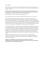
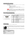
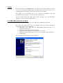
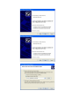
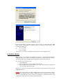
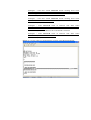
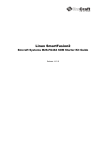
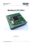
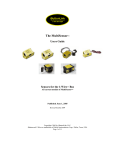
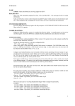
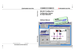
MOD-RFID1356
user's manual
All boards produced by Olimex are ROHS compliant
Rev. C, June 2015
Copyright(c) 2008, OLIMEX Ltd, All rights reserved
DISCLAIMER
© 2015 Olimex Ltd. Olimex®, logo and combinations thereof, are registered trademarks of
Olimex Ltd. Other product names may be trademarks of others and the rights belong to their
respective owners.
The information in this document is provided in connection with Olimex products. No
license, express or implied or otherwise, to any intellectual property right is granted by
this document or in connection with the sale of Olimex products.
Both the hardware and the software projects are kept private.
It is possible that the pictures in this manual differ from the latest revision of the board.
The product described in this document is subject to continuous development and
improvements. All particulars of the product and its use contained in this document are
given by OLIMEX in good faith. However all warranties implied or expressed including but
not limited to implied warranties of merchantability or fitness for purpose are excluded. This
document is intended only to assist the reader in the use of the product. OLIMEX Ltd. shall
not be liable for any loss or damage arising from the use of any information in this document
or any error or omission in such information or any incorrect use of the product.
This evaluation board/kit is intended for use for engineering development, demonstration,
or evaluation purposes only and is not considered by OLIMEX to be a finished end-product
fit for general consumer use. Persons handling the product must have electronics training
and observe good engineering practice standards. As such, the goods being provided are not
intended to be complete in terms of required design-, marketing-, and/or manufacturingrelated protective considerations, including product safety and environmental measures
typically found in end products that incorporate such semiconductor components or circuit
boards.
Olimex currently deals with a variety of customers for products, and therefore our
arrangement with the user is not exclusive. Olimex assumes no liability for applications
assistance, customer product design, software performance, or infringement of patents or
services described herein.
THERE IS NO WARRANTY FOR THE DESIGN MATERIALS AND THE
COMPONENTS USED TO CREATE MOD-RFID1356-BOX. THEY ARE CONSIDERED
SUITABLE ONLY FOR MOD-RFID1356-BOX.
INTRODUCTION:
MOD-RFID1356 is an RFID station, able to interact with ISO15693
compliant VICC transponders. All the complexity of RFID tag detection,
verification and decoding are handled by MOD-RFID1356. Custom
command requests can be initiated to facilitate VICC EEPROM read and
write operations.
MOD-RFID1356 supports two distinctive modes of operation, easily
switched by a single button press. It can emulate USB HID keyboard and
input the read TAG ID directly to any Windows application, including the
venerable Notepad. Or it can emulate USB CDC serial port for easy access
from custom user applications using standard code for COM port access.
FEATURES:
-
Supports ISO15693 compliant VICC transponders like EM4233.
Base RFID frequency 13,56MHz;
USB port connection to PC;
Two modes of operation, easily changed by pressing the button;
USB HID keyboard emulation mode;
USB CDC serial port emulation mode;
Simple command-line interface in USB CDC mode for configuration,
data acquisition and initiation of custom command requests;
Two LEDs indicating device status and tag presence;
Support for continuous and periodic RF scanning to better suit user
power requirements;
Ships with default mode USB HID and default configuration:
continuous read, scan always, LEDs activated;
ELECTROSTATIC WARNING:
The MOD-RFID1356 board is shipped in protective anti-static packaging.
The board must not be subject to high electrostatic potentials. General
practice for working with static sensitive devices should be applied when
working with this board.
REQUIREMENTS:
Cables: 1.8 meter USB A-B cable.
Software:
Software needed for USB HID keyboard mode:
- Notepad or other text editor.
Software needed for USB CDC mode:
- HyperTerminal or other terminal program.
SUPPORTED RFID TAGS/VICC:
MOD-RFID1356 supports RFID transponder tags with the following
characteristics:
- EM4233 64 bit read only tag
- 13.56MHz carrier frequency;
- 1 out of 4 transmission encoding (VCD to VICC);
- High data rate (26,48kbit/s) reception encoding using one subcarrier frequency.
CAVEAT: MOD-RFID1356 does not support reliably the anti-collision
algorithm as defined in the ISO15693 standard. It will work reliably only if
there is a single VICC in the vicinity or if there is no RF collision. If there is
an RF collision, supposedly because of two VICCs with almost identical
UIDs, it might not detect both of them.
UEXT CONNECTOR SCHEMATICS:
If you have to connect to the UART note that the UART baud rate is 57600.
pin
1
2
3
Abbrev.
NC
GND
RXD
4
TXD
5
6
7
8
9
10
NC
NC
NC
NC
NC
NC
UEXT
description
Not Connected
Ground
UART Receive Data (MOD-RFID1356BOX input)
UART Transmit Data (MODRFID1356-BOX output)
Not Connected
Not Connected
Not Connected
Not Connected
Not Connected
Not Connected
POWER SUPPLY:
Normally the device is supplied from USB.
MOD-RFID1356-BOX can be connected to external 6-9V DC power supply.
This can relief the USB hub power supply when device is in USB HID or
USB CDC mode. External power supply is mandatory for UART mode of
operation.
Note: If you want to use the board with external power supply, you have first to
switch to UART mode when your board is connected to the USB (USB HID or USB
CDC mode).
POWER SUPPLY CABLE CONNECTION
Connect to...
Pin
1
+6-9V DC
2
GND
LEDS:
In normal mode the GREEN LED is on whenever the RF antenna circuit is
active and scanning for RFID tags. The RED LED switches on whenever a
valid RF TAG ID is being scanned and decoded successfully.
The LEDs can be switched off to save power consumption. See the
“Command Line Interface” section for more information.
In boot loader mode the LEDs have other meaning. See the “Firmware
Upgrade” section for more information.
PC DRIVER INSTALLATION:
Drivers for the USB HID mode are integrated in Windows XP/Vista.
The driver for USB CDC mode is available from our website. Windows
installation steps are the following:
1. Download and unzip the file “MOD-RFID1356-drivers.zip” in a
temporary directory.
2. Plug the programmer in the USB port.
3. Point the Device Wizard to the temporary directory.
4. Windows will complain that drivers are not signed. Click “Continue”.
5. Click finish.
Screen shots of the steps are shown below:
Linux distributions normally include drivers both for USB HID and USB
CDC classes. Depending on which driver is loaded in the kernel, user
should look either for
/dev/ttyACMn
or
/dev/ttyUSBn
where "n" is a number, assigned by the kernel to the plugged device.
USB HID MODE:
When device is connected via USB to a host PC it will represent itself as
USB HID keyboard. When an RFID transponder is detected in the vicinity,
the module will type the HEX-representation of the transponder ID.
To use
1.
2.
3.
the device in this mode:
Open Notepad.
Plug in the device in the USB port of the PC.
Put an RFID tag in front of the device. The TAG ID will be entered in
the currently opened text file.
There is no need for OS driver because all major operating systems include
USB HID drivers.
NOTE: This mode does not allow configuration of device parameters. MODRFID1356 is shipped with default configuration for continuous read. If this
must be changed then device must be switched to USB CDC mode and
configured using the serial command line interface.
USB CDC MODE:
In this mode the device represents itself as USB CDC virtual serial port. It
provides a simple shell-like command line interface for configuring and
interacting with the module. The device echoes back the typed characters
and waits for Carriage Return (Enter) before processing the line input. See
“Command Line Interface” for more information on the supported
commands.
Any terminal software can be used to open the COM port, assigned by the
OS, and type in commands.
UART MODE:
This mode can be used when we want to attach the RFID1356-BOX to
another board via the UEXT connector. This would allow the other mode to
receive the IDs of the tags read by the reader. This setup of two boards
establishes a UART connection over the UEXT. It is imperative to notice
that when the board is in this mode the MOD-RFID1356-BOX CAN NOT
receive commands via the UART. This means the module cannot be
configured while in UART mode. It can only send the ID of the tag read.
The reader expects the peer to be configured with 57600 bps, 8bit
character, no parity, 1 stop bit. Again, all entered characters are echoed
back.
NOTE: This mode does not allow configuration of device parameters. MODRFID1356 is shipped with default configuration for continuous read. If this
must be changed then device must be switched to USB CDC mode and
configured using the serial command line interface.
SWITCHING OPERATING MODES:
The current mode of operation can be selected by pressing and holding the
button of the device. After two seconds the LEDs will start to blink and will
show the code for the next selected mode. When button is released, the
device will reboot and enter the selected mode. Selected mode is
remembered between power downs. The assigned codes are:
LED Status
Red
Green
Description
Previous State
State After Button Is
Released
blinks
off
USB CDC
USB HID
off
blinks
USB HID
USB CDC
blinks
blinks
USB CDC
UART
COMMAND LINE INTERFACE (USB CDC mode):
The command line interface, available in USB CDC mode, allows device
configuration and reading of successfully decoded TAG IDs. Just open the
serial port assigned to MOD-RFID1356 using HyperTerminal or similar
terminal program, and start typing commands.
Important: when MOD-RFID1356-BOX is in UART mode it can't receive
commands. It can only read tags and return the information.
For the impatient: type '?' and press enter to see a short help for the
supported commands. Any typed character will be echoed back; 'enter' will
force the module to process the input command line.
1. Command ?
This command prints a short help message, describing the available
commands and their arguments.
2. Command i
This command prints a short information about firmware version,
hardware board revision, and currently selected configuration.
3. Command b
This command forces the device to enter boot loader mode. After
executing this command the device will disconnect itself from USB,
switch to boot loader mode, and reconnect itself in anticipation of
receiving a firmware upgrade image. See the section “Firmware
Upgrade” for more information.
4. Command r
This command is only valid if device is in single read mode (see
below). It will trigger a single TAG read. If TAG ID is successfully
read, it will be printed. Otherwise if operation timeouts, zeros will be
printed.
5. Command msXX
Set single read mode. The XX parameter must be a decimal value,
indicating the TAG read timeout in seconds.
Example – setting single read mode with 15 seconds timeout:
ms15
6. Command mcFR
Set continuous read mode with frequency F (Hz). R is for
compatibility with other Olimex products and is otherwise ignored if
present. Both F and R must be single digit decimal numbers.
If F is 0 then RF antenna is constantly switched on and the device
scans continuously for tags. Otherwise if F is 1-5, the device will
switch the antenna on F times per second.
Example – continuous scanning:
mc0
Example – scan once per second:
mc1
7. Command mlE
Set LED mode. If E is 0, LEDs will be disabled. Otherwise if E is 1,
LEDs will be enabled.
Example – enabling LEDs:
ml1
Example – disabling LEDs to conserve power:
ml0
8. Command cT1,T2,FFCCDD...DD
Issue custom command request. T1 and T2 are timeouts in
milliseconds. T1 shows how much to wait in RF silence before
issuing timeout. T2 defines the total reception timeout, no matter
what is decoded from the RF field. Typical values for both are 50 to
100ms. After them is the hexadecimal representation of the request
which will be issued. FF is the request flags byte, CC is the comand
code, followed by zero or more data bytes. CRC is automatically
handled by MOD-RFID1356.
If answer was correctly received and decoded the response format
would be:
<FFAA...
where FF is the response flags byte, followed by one or more
response data bytes.
On error the following is returned:
!eXX
where XX is a decimal number code of the occurred error. In general
the VICC error code bytes are propagated, along with some
additional MOD-RFID1356 specific error codes. See the table below
for error code definitions.
Error
code
Description
1
Command code request not supported.
2
Request format not recognized.
3
Command option is not supported.
14
Generic error.
16
Specified block does not exist.
18
Specified block is locked.
19
Block write error.
20
Block lock error.
160
Power check failed.
256
VICC response timeout.
257
MOD-RFID1356 does not posses enough memory
to complete the requested operation.
258
VICC response has incorrect CRC.
Please consult the ISO15693 standard and your VICC datasheet for
more information about request and answer formats.
Example – read four 32-bit EEPROM words starting from word
number 2, addressed version, both timeouts set to 100ms,
addressing VICC UID with 7B8C0016010416E0:
c100,100,20237B8C0016010416E00204
Example – read four 32-bit EEPROM words starting from word
number 2, non-addressed version:
c100,100,00230204
Example – write EEPROM word at address 0xA with value
0x11223344, addressed version, addressing VICC UID with
7B8C0016010416E0:
c100,100,20217B8C0016010416E00A11223344
Example – write EEPROM word at address 0xA with value
0x11223344, non-addressed version:
c100,100,00210A11223344
Below is a screen shot of command line session using HyperTerminal:
FIRMWARE UPGRADE:
MOD-RFID1356 contains a built-in boot loader for easy firmware upgrade.
Device enters boot loader mode if the application FLASH section is
corrupted. To force the device to enter boot loader mode for manual
firmware update do the following:
1. Disconnect the device from USB.
2. Press and hold the button.
3. Power up the device by connecting it to USB.
4. Device now must be in boot loader mode, indicated by the LED light
sequence:
a. RED on, GREEN off.
b. RED off, GREEN on.
c. RED off, GREEN off.
Button can now be released. The device will stay in boot loader mode until
it is power cycled.
Boot loader implements the standard protocol XMODEM with CRC16 for
firmware update. User is free to use his favorite terminal client
(HyperTerminal, minicom, etc) to upload the firmware images taken from
our website. Boot loader uses an USB virtual serial port that is baudrate
agnostic.
As an alternative we provide a simple Windows GUI application for users
who don’t want to or cannot use terminal software.
After the firmware image is uploaded the target will blink the GREEN LED if
update was successful, otherwise it will blink the RED LED if firmware
image was invalid or update was unsuccessful. Device stays in this state
until it is power cycled.
ORDER CODE:
MOD-RFID1356 – assembled and tested (no kit, no soldering required)
How to order?
You can order to us directly or by any of our distributors. Check our web
https://www.olimex.com for more info.
Revision history:
REV.A
- created
May 2008
REV.B
- created
February 2013
REV.C
- created
June 2015
For product support, hardware information and error reports mail to: [email protected]. Note that we are
primarily a hardware company and our software support is limited.
Please consider reading the paragraph below about the warranty of Olimex products.
Warranty and returns:
Our boards have lifetime warranty against manufacturing defects and components.
During development work it is not unlikely that you can burn your programmer or development board. This is
normal, we also do development work and we have damaged A LOT of programmers and boards during our
daily job so we know how it works. If our board/programmer has worked fine then stopped, please check if you
didn't apply over voltage by mistake, or shorted something in your target board where the programmer was
connected etc. Sometimes boards might get damaged by ESD shock voltage or if you spill coffee on them during
your work when they are powered.
Please note that warranty do not cover problems caused by improper use, shorts, over-voltages, ESD shock etc.
If the board has warranty label it should be not broken. Broken labels void the warranty, same applies for boards
modified by the customer, for instance soldering additional components or removing components – such boards
will be not be a subject of our warranty.
If you are positive that the problem is due to manufacturing defect or component you can return the board back
to us for inspection.
When we receive the board we will check and if the problem is caused due to our fault and we will
repair/replace the faulty hardware free of charge, otherwise we can quote price of the repair.
Note that all shipping back and forth have to be covered by the customer. Before you ship anything back you
need to ask for RMA. When you ship back please attach to it your shipping address, phone, e-mail, RMA# and
brief description of the problem. All boards should be sent back in antistatic package and well packed to prevent
damages during the transport.