1
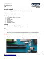
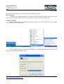
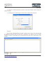
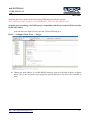
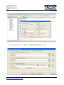
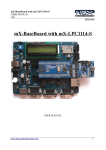
mX-LPC2148-S
USER MANUAL
v1.0
30/11/2010
mX-LPC2148-S
USER MANUAL
http://shop.ngxtechnologies.com
1
mX-LPC2148-S
USER MANUAL
v1.0
30/11/2010
Table of Contents
Introduction .........................................................................................................................................3
Features.................................................................................................................................................3
Hardware..........................................................................................................................................3
Software ..........................................................................................................................................3
Getting Started .....................................................................................................................................4
Hardware .........................................................................................................................................4
Software ..........................................................................................................................................4
Setup.....................................................................................................................................................4
Hardware..........................................................................................................................................4
Software...........................................................................................................................................5
Validating mX-LPC2148-S Board........................................................................................................5
Programming mX-LPC2148-S ............................................................................................................9
Appendix............................................................................................................................................10
mX-LPC2148-S Board Utilities.....................................................................................................10
USB Virtual COM Port Installation For Windows XP..................................................................10
USB Boot-loader ...........................................................................................................................12
Schematics..........................................................................................................................................15
Sample Code.......................................................................................................................................15
Information.........................................................................................................................................16
Revision History......................................................................................................................16
Legal.........................................................................................................................................16
Disclaimers ..............................................................................................................................16
Trademarks ..............................................................................................................................16
http://shop.ngxtechnologies.com
2
mX-LPC2148-S
USER MANUAL
v1.0
30/11/2010
Introduction
The mX-LPC2148-S is an add on board to the mX-BaseBoard. The mX-S signifies it as a
stamp module for mX-BaseBoard. The stamp board features LPC2148 from NXP, based on ARM
7TDMI.
Features
The mX-LPC2148-S is mounted on a board with connecting pins.
Hardware
•
•
32 Khz crystal for RTC
12 Mhz for Controller
•
•
2x16 with contrast control & back light
SD Card connector
•
•
•
•
•
•
Power Jack
Power Switch
Reset Button
ISP Button
External interrupt Button
Buzzer
•
•
Audio Jack
20 pin JTAG header
•
•
•
•
•
•
•
PS/2 keyboard
VGA connector
Serial Connector 0
Serial Connector 1
Preset for ADC
On board EEPROM
GPIO brought to male header pins
Note: Features are dependent on the stamp.
Software
Precompiled firmware to test the peripherals on the mX-BaseBoard with stamp is preloaded
and available here.
http://shop.ngxtechnologies.com
3
mX-LPC2148-S
USER MANUAL
v1.0
30/11/2010
Getting Started
Before starting you would need the following things handy and ready.
Requirement
The requirement is put in two sections.
Hardware
•
•
•
•
•
•
Power adapter – rating 7.5 V, 1 AMP
SD card
USB mini cable
Serial cable
PS/2 Keyboard
Headphones / Speaker
Software
•
•
PC with Linux OS / Windows XP OS
Use minicom as terminal software / HyperTerminal
Setup
Hardware
The mX-LPC2148-S board should be mounted on the board with a particular alignment.
Note: Improper mounting of the stamp board on mX-BaseBoard may damage the stamp board and /
the mX- BaseBoard.
The GND pin on stamp board should be aligned with the pin 1 of P9 female header on
BaseBoard. Refer to the marking as shown in the image below.
http://shop.ngxtechnologies.com
4
mX-LPC2148-S
USER MANUAL
v1.0
30/11/2010
Software
•
•
PC with WINDOWS XP
Hyperterminal
The mX-LPC2148-S comes with a USB bootloader and the binaries from NGX Technologies to
validate the mX-BaseBoard.
Validating mX-LPC2148-S Board
Once you have all these accessories connected to the mX-BaseBoard you can run a simple
test to verify the proper working of all the peripherals. It is highly recommended that you test all the
peripherals as soon you receive the BaseBoard. The mX-LPC2148-S is shipped with the preloaded
bootloader firmware and binaries to test all the peripherals.
When you receive the mX-LPC2148-S board, it will be loaded will firmware for all
peripherals. On connecting the power supply a default message will appear on LCD. The interfaces
are activated in the following manner: LED D1 on stamp, Ext Int, LCD, keyboard, UART0, UART
1, DAC, ADC, EEPrROM, Virtual COM port on USB.
LED
The LED D1 on the stamp board blinks for a few times.
User Interface Switch (Ext Int)
The Switch SW6 is connected to one of the external interrupt line of controller. To test this
interface simply press the switch and you should hear the beep sound on the buzzer. This confirms
that both the interrupt line and the buzzer module are working fine.
LCD display
A default message “NGX TECHNOLOGIES” will be displayed and later status of SD/MMC
and I2C is displayed. The back light of LCD can be controlled by connecting jumper to appropriate
http://shop.ngxtechnologies.com
5
mX-LPC2148-S
USER MANUAL
v1.0
30/11/2010
pins of JP5. The contrast of LCD can be varied using the POT R19.
PS/2 keyboard
To enable PS/2 connect jumper to J2. Connect a PS/2 keyboard to this connector. Now press
any key on the keyboard. The user can see which key he/she has pressed on the LCD.
UART0 & UART1
Open the hyper terminal as shown in the below image. To test the UART you can use either
a full modem or half modem cable.
Click on hyper terminal a “Connection Description” window opens. Enter a name under the
name tab e.g. BlueBoard and click OK.
http://shop.ngxtechnologies.com
6
mX-LPC2148-S
USER MANUAL
v1.0
30/11/2010
A “Connect To” window opens where you have to select the COM port. In this example it is
COM1.Click OK.
A “COM1Properties” window appears. Set the values as shown below.Click OK.
Click OK.
Next an empty “BlueBoard-Hyper Terminal” window opens as shown. Now make sure that
the BlueBoard is powered and the serial port is connected to the respective port to be tested
(UART0 or UART1). By pressing any key from keyboard the same will be echoed back on the
terminal.
For UART0 -- (J4)
For UART1 -- (J5)
http://shop.ngxtechnologies.com
7
mX-LPC2148-S
USER MANUAL
v1.0
30/11/2010
UART0 can also be used for serial programming. If the selected bootloader mode is Manual
then Half modem cable should be used, else if it is in Auto mode use full modem cable. Note that
after programming in auto mode the serial cable should be disconnected.
Audio jack (DAC)
Connect a headset to the audio jack (U4) connector. You should hear some random sound.
The sound is heard only for few seconds after power ON or RESET.
ADC
The ADC is connected to a potentiometer (R14). To test the ADC turn the potentiometer, as
the position varies the output number on the LCD varies.
USB
Before moving ahead with this section, refer to USB Virtual COM Port Installation for
Windows XP section.
Connect the USB cable to USB connector. The USB enumeration can be checked in device
manager. The mX-LPC2148-S enumerates as a Virtual COM port. To test the Virtual COM port we
can test it as we tested the UART0/1 of mX-LPC2148-S.
JTAG connector
To enable debugging on the board connect jumper to P8 and connect the JTAG to debug
port. We have successfully tested the mX-LPC2148-S with JTAG interface using a Wiggler Clone
JTAG. To test this feature you need to have the necessary software support on your PC.
http://shop.ngxtechnologies.com
8
mX-LPC2148-S
USER MANUAL
v1.0
30/11/2010
Buzzer
Connect jumper to JP1, when the board is turned on or RESET you will hear a beep after
few seconds. This is how the user can confirm the status of the Buzzer.
SD/MMC connector
Insert a SD card in the SD card holder (U1), the status of the SD card will be displayed on
LCD upon power cycle or reset of the mX-LPC2148-S. If the SD card is inserted properly “SD card
– OK” is displayed on LCD else it displays “SD card- Not OK”. The board was tested with a
Kingston’s 1GB SD card.
Note: The SD/MMC card being tested should be formatted with FAT file system (Not FAT32 or
NTFS format).
I2C (EEPROM)
On the board at U8 a EEPROM with I 2C interface is present. The firmware tests it and
diplays “I2C FLASH – PASS”.
Before moving ahead with this section, refer to USB Virtual COM Port Installation for
Windows XP section.
Connect the USB cable to USB connector. The USB enumeration can be checked in device
manager. The mX-LPC2148-S enumerates as a Virtual COM port. To test the Virtual COM port we
can test it as we tested the UART0/1 of mX-LPC2148-S.
Programming mX-LPC2148-S
mX-LPC2148-S can be programmed through NGX prallel port JTAG, NGX USB JTAG or
through serial port using ‘Flash Magic’. ‘Flash Magic’ is a freeware windows utility used download
the hex file format onto the board. Flash Magic can be downloaded from here
http://www.flashmagictool.com/. If your PC does not have a serial port; use a USB to serial
converter to download the hex file using the Flash Magic utility. For programming with JTAG your
system should have a parallel port or you can use the USB to JTAG from NGX Technologies and
the supporting IDE which can communicate to the processor core over JTAG interface. We have
successfully tested mX-LPC2148-S with wiggler clone JTAG and USB JTAG with CrossWorks
IDE. A LINUX utility to download the hex file can be found here
http://www.pjrc.com/arm/lpc2k_pgm/.
Programming mX-LPC2148-S Through ISP
The mX-LPC2148-S can be programmed through ISP in Manual Mode
To program in Manual mode you need a half serial cable (which just has TX, RX and GND
wire connected). connect the serial cable to UART0 (J4) and power the board.
To make the board enter programming mode
• Hold down SW5 (ISP) and SW4 (RESET), then release SW5 first and finally SW4
http://shop.ngxtechnologies.com
9
mX-LPC2148-S
USER MANUAL
v1.0
30/11/2010
• The controller enters the bootloader mode if during reset the SW5 pin is low
Programming and Debugging with JTAG
The mX-LPC2148-S can be programmed and debugged either using parallel port or USB
JTAG.
•
NGX Parallel Port JTAG using H-JTAG (refer here)
•
NGX USB JTAG
Appendix
mX-LPC2148-S Board Utilities
For working with mX-LPC2148-S board there are certain tools that need to be installed. The
tools required are:
Flash Magic Tool.
The flash magic tool can be downloaded from the following link:
http://www.flashmagictool.com/
H-JTAG
http://www.hjtag.com/
For LINUX machines you may use http://www.pjrc.com/arm/lpc2k_pgm/
Tool chain
To be able to generate the hex or the binary file the user needs to install the tool chain for
ARM based microcontrollers. Any toolchain can be used as long as it is able to generate the
necessary files for downloading onto the mX-LPC2148-S. Here are few toolchain suggestions:
GNUARM Toolchain: http://winarm.scienceprog.com/winarm-tools/prepare-gnuarm-compilertoolchain-for-windows.html
Crossworks IDE: http://www.rowley.co.uk/arm/
IAR Systems: http://www.iar.com
Build your own GCC compier http://www.forum.ngxtechnologies.com/viewtopic.php?f=3&t=5
Debug with OpenOCD http://www.forum.ngxtechnologies.com/viewtopic.php?f=3&t=12
USB Virtual COM Port Installation For Windows XP
The USB in mX-LPC2148-S might not get enumerated if it does not find the appropriate
driver for it. To check USB enumeration status Right Click on “My Computer” icon and select
Manage. A “Computer Management” window opens. In this select Device Manager as shown
below:
The device uses the usbser.sys driver. This driver file is not unpacked in Windows by default
and needs to be extracted from a Windows .cab file which should be in the C:\WINDOWS\Driver
Cache\i386 directory for Windows XP SP2. Change directory to C:\WINDOWS\Driver
http://shop.ngxtechnologies.com
10
mX-LPC2148-S
USER MANUAL
v1.0
30/11/2010
Cache\i386 expand the CAB file by running the below command in Command-Prompt
expand sp2.cab -f:usbser.sys C:\WINDOWS\system32\drivers
Note: On some systems like the XP home edition; extraction of driver files from cab files might not
be supported. In such situation the user can download the usbser.sys file from http://blueboardlpc214x.googlecode.com/files/usbser.sys and copy it to C:\WINDOWS\system32\drivers folder
Next, download the usbser.inf file from http://blueboard-lpc214x.googlecode.com/files/usbser.inf
Place it in any convenient folder. Plug in the device
A Hardware Update Wizard opens up. Select the second option as shown and Click Next.
Note: If the wizard does not open up automatically then the user needs to go the ‘Device Manager’
window and right click on the device and select ‘update driver’
http://shop.ngxtechnologies.com
11
mX-LPC2148-S
USER MANUAL
v1.0
30/11/2010
Set the new hardware Wizard to search a specific location for the driver, and specify the
folder containing usbser.inf
The Wizard will prompt for the location of usbser.sys. Specify its location
(i.e. C:\WINDOWS\system32\drivers) and Click Next.
The installation should now complete and indicate the device has been installed. The device
should now get enumerated under “Ports(COM & LPT)” option in ‘Device Manager’ window.
To test the USB interface open Hyper Terminal by selecting the COM port specified by the
system. The COM port number assigned to the USB serial device is not fixed and can change. To
know the current COM port number the user needs to look into the ‘Device Manager’ page under
“Ports(COM & LPT)” . After selecting the appropriate COM PORT, press any key on keyboard; a
message will be displayed in the hyper terminal window as shown below. This confirms that the
USB interface on the mX-LPC2148-S is fine.
USB Boot-loader
The mX-LPC2148-S comes pre-loaded with the USB boot-loader firmware. With the USB
boot-loader you can simply drag and drop your compiled binary file onto the device as you would
with any USB flash drive and it will update itself accordingly. Serial port is not required for
flashing. To make the board enter boot-loader mode follow the steps below.
How To Enter USB Boot Loader Mode
After loading USB boot-loader firmware to the mX-LPC2148-S, hold down SW6 (USBBL)
and SW4 (RESET), then release SW6 first and finally SW4. Now the pre-loaded USB boot-loader
allows you to enumerate the board as a Mass Storage Device. Drag the compiled binary file and
http://shop.ngxtechnologies.com
12
mX-LPC2148-S
USER MANUAL
v1.0
30/11/2010
drop onto the device and reset the board using SW4 and the firmware executes
Note: USB boot-loader firmware is provided as NGX_LPC2148_BT_LDR.hex only.
Steps involved in making your KEIL project compatible with the pre-loaded USB boot-loader
in mX-LPC2148-S
1) As shown in the figure below Open the µVision IDE and go to
Flash --> Configure Flash Tools --> Target
2) Change the start address of on-chip IROM1 memory from 0 to 0x2000 as shown in figure
below. This is the area where user program is placed and has to run when the controller is
reset.
http://shop.ngxtechnologies.com
13
mX-LPC2148-S
USER MANUAL
v1.0
30/11/2010
3) Here in fig. as below Go to Flash --> Configure Flash Tools --> User
http://shop.ngxtechnologies.com
14
mX-LPC2148-S
USER MANUAL
v1.0
30/11/2010
Insert the user command in Run #1 ticking the check box. After compile and build the entire
project, from elf it creates a hex file along with the hex file there will be another file with the
extension .axf. This user command is used to convert .axf file to .bin. Here in fig. above
firmware.axf is converted to firmware.bin which is used for drag drop programming with the USB
boot-loader that allows you to enumerate the board as a Mass Storage Device.
Note: The location of .axf file in the user command must be same where its located in the project
folder. In the fig. above the default location of .axf file is folder obj in the project folder so the user
commands goes like .\obj\firmware.axf
Schematics
Refer to the documentation here.
Sample Code
Download the zipped file here.
http://shop.ngxtechnologies.com
15
mX-LPC2148-S
USER MANUAL
v1.0
30/11/2010
Information
Revision History
version: v1.0 author: Milind Kakati
Legal
NGX Technologies Pvt. Ltd. provides the enclosed product(s) under the following conditions:
This evaluation board/kit is intended for use for ENGINEERING DEVELOPMENT, DEMONSTRATION, EDUCATION OR
EVALUATION PURPOSES ONLY and is not considered by NGX Technologies Pvt. Ltd to be a finished end-product fit for general
consumer use. Persons handling the product(s) must have electronics training and observe good engineering practice standards. As
such, the goods being provided are not intended to be complete in terms of required design-, marketing-, and/or manufacturingrelated protective considerations, including product safety and environmental measures typically found in end products that
incorporate such semiconductor components or circuit boards. This evaluation board/kit does not fall within the scope of the
European Union directives regarding electromagnetic compatibility, restricted substances (RoHS), recycling (WEEE), FCC, CE or
UL and therefore may not meet the technical requirements of these directives or other related directives.
The user assumes all responsibility and liability for proper and safe handling of the goods. Further, the user indemnifies NGX
Technologies from all claims arising from the handling or use of the goods. Due to the open construction of the product, it is the
user’s responsibility to take any and all appropriate precautions with regard to electrostatic discharge.
EXCEPT TO THE EXTENT OF THE INDEMNITY SET FORTH ABOVE, NEITHER PARTY SHALL BE LIABLE TO THE
OTHER FOR ANY INDIRECT, SPECIAL, INCIDENTAL, OR CONSEQUENTIAL DAMAGES.
NGX Technologies currently deals with a variety of customers for products, and therefore our arrangement with the user is not
exclusive. NGX Technologies assumes no liability for applications assistance, customer product design, software performance, or
infringement of patents or services described herein.
Please read the User’s Guide and, specifically, the Warnings and Restrictions notice in the User’s Guide prior to handling the product.
This notice contains important safety information about temperatures and voltages.
No license is granted under any patent right or other intellectual property right of NGX Technologies covering or relating to any
machine, process, or combination in which such NGX Technologies products or services might be or are used.
Disclaimers
Information in this document is believed to be reliable and accurate. However, NGX Technologies does not give any representations
or warranties, expressed or implied, as to the completeness or accuracy of such information and shall have no liability for the
consequences of use of such information.
NGX Technologies reserves the right to make changes to information published in this document, at any time and without notice,
including without limitation specifications and product descriptions. This document replaces and supercedes all information supplied
prior to the publication hereof.
Trademarks
All referenced trademarks, product names, brands and service names are the property of their respective owners.
http://shop.ngxtechnologies.com
16