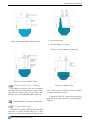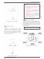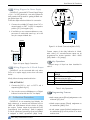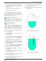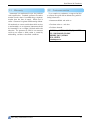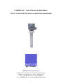
1
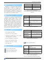
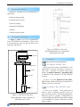
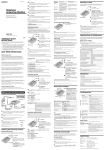
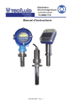
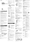
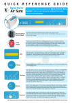
CAPVEL-LP : User Manual & Datasheet
Contact level transmitter based on capacitance measurement
R
SAPCON
Instruments Pvt.Ltd.
ISO 9001:2008, ISO 14001 and ISO 22000 Certified Company
Address: 131, Palshikar Colony, Indore - 452004 (India)
Phone: +91-731-4757575 Fax: +91-731-2475475
email: [email protected] web: www.sapconinstruments.com
1
User Manual & Datasheet
Contents
1
2
3
4
Introduction . . . . . . . . . . . . . . . . .
Operating Principle . . . . . . . . . . . . .
Features . . . . . . . . . . . . . . . . . . .
Specifications . . . . . . . . . . . . . . . .
4.1 General Specifications . . . . . . . . . .
4.2 Mechanical Specifications . . . . . . . .
4.3 Electrical Specifications . . . . . . . . .
4.4 Output Specifications . . . . . . . . . .
5 Application Note . . . . . . . . . . . . . .
6 Dimensional Layout . . . . . . . . . . . . .
7 Guidelines . . . . . . . . . . . . . . . . . .
7.1 Tank Mounting Installations . . . . . .
7.1.1 For Regular Metallic Tank . . . . .
7.1.2 For Regular Non Meatallic tanks . .
7.1.3 Tanks contain Stirrer or Agitator . .
7.2 Mounting with Process connections . .
7.2.1 Threaded Mountings . . . . . . . .
7.2.2 Flange Mountings . . . . . . . . . .
7.3 Electrical Connections . . . . . . . . . .
7.3.1 Wiring Diagram for Power Supply .
7.3.2 Wiring Diagram for 4-20 mA Output
8 Calibration Procedure . . . . . . . . . . . .
8.1 Key Operations . . . . . . . . . . . . .
8.2 Programming Features . . . . . . . . .
8.3 Programming Procedure . . . . . . . .
8.3.1 Programming Steps . . . . . . . . .
8.3.2 Indirect Calibration . . . . . . . . .
9 Error Indication & Remedies . . . . . . . .
10 Handling Precaution . . . . . . . . . . . .
11 Warranty . . . . . . . . . . . . . . . . . .
12 Customer service . . . . . . . . . . . . . .
R
SAPCON
Instruments Pvt.Ltd.
.
.
.
.
.
.
.
.
.
.
.
.
.
.
.
.
.
.
.
.
.
.
.
.
.
.
.
.
.
.
.
.
.
.
.
.
.
.
.
.
.
.
.
.
.
.
.
.
.
.
.
.
.
.
.
.
.
.
.
.
.
.
.
.
.
.
.
.
.
.
.
.
.
.
.
.
.
.
.
.
.
.
.
.
.
.
.
.
.
.
.
.
.
.
.
.
.
.
.
.
.
.
.
.
.
.
.
.
.
.
.
.
.
.
.
.
.
.
.
.
.
.
.
.
.
.
.
.
.
.
.
.
.
.
.
.
.
.
.
.
.
.
.
.
.
.
.
.
.
.
.
.
.
.
.
.
.
.
.
.
.
.
.
.
.
.
.
.
.
.
.
.
.
.
.
.
.
.
.
.
.
.
.
.
.
.
.
.
.
.
.
.
.
.
.
.
.
.
.
.
.
.
.
.
.
.
.
.
.
.
.
.
.
.
.
.
.
.
.
.
.
.
.
.
.
.
.
.
.
.
.
.
.
.
.
.
.
.
.
.
.
.
.
.
.
.
.
.
.
.
.
.
.
.
.
.
.
.
.
.
.
.
.
.
.
.
.
.
.
.
.
.
.
.
.
.
.
.
.
.
.
.
.
.
.
.
.
.
.
.
.
.
.
.
.
.
.
.
.
.
.
.
.
.
.
.
.
.
.
.
.
.
.
.
.
.
.
.
.
.
.
.
.
.
.
.
.
.
.
.
.
.
.
.
.
.
.
.
.
.
.
.
.
.
.
.
.
.
.
.
.
.
.
.
.
.
.
.
.
.
.
.
.
.
.
.
.
.
.
.
.
.
.
.
.
.
.
.
.
.
.
.
.
.
.
.
.
.
.
.
.
.
.
.
.
.
.
.
.
.
.
.
.
.
.
.
.
.
.
.
.
.
.
.
.
.
.
.
.
.
.
.
.
.
.
.
.
.
.
.
.
.
.
.
.
.
.
.
.
.
.
.
.
.
.
.
.
.
.
.
.
.
.
.
.
.
.
.
.
.
.
.
.
.
.
.
.
.
.
.
.
.
.
.
.
.
.
.
.
.
.
.
.
.
.
.
.
.
.
.
.
.
.
.
.
.
.
.
.
.
.
.
.
.
.
.
.
.
.
.
.
.
.
.
.
.
.
.
.
.
.
.
.
.
.
.
.
.
.
.
.
.
.
.
.
.
.
.
.
.
.
.
.
.
.
.
.
.
.
.
.
.
.
.
.
.
.
.
.
.
.
.
.
.
.
.
.
.
.
.
.
.
.
.
.
.
.
.
.
.
.
.
.
.
.
.
.
.
.
.
.
.
.
.
.
.
.
.
.
.
.
.
.
.
.
.
.
.
.
.
.
.
.
.
.
.
.
.
.
.
.
.
.
.
.
.
.
.
.
.
.
.
.
.
.
.
.
.
.
.
.
.
.
.
.
.
.
.
.
.
.
.
.
.
.
.
.
.
.
.
.
.
.
.
.
.
.
.
.
.
.
.
.
.
.
.
.
.
.
.
.
.
.
.
.
.
.
.
.
.
.
.
.
.
.
.
.
.
.
.
.
.
.
.
.
.
.
.
.
.
.
.
.
.
.
.
.
.
.
.
.
.
.
.
.
.
.
.
.
.
.
.
.
.
.
.
.
.
.
.
.
.
.
.
.
.
.
.
.
.
.
.
.
.
.
.
.
.
.
.
.
.
.
.
.
.
.
.
.
.
.
.
.
.
.
.
.
.
.
.
.
.
.
.
.
.
.
.
.
.
.
.
.
.
.
.
.
.
.
.
.
.
.
.
.
.
.
.
.
.
.
.
.
.
.
.
.
.
.
.
.
.
.
.
.
.
.
.
.
.
.
.
.
.
.
.
.
.
.
.
.
.
.
.
.
.
.
.
.
.
.
.
.
.
.
.
.
.
.
.
.
.
.
.
.
.
.
.
.
.
.
.
.
.
.
.
.
.
.
.
.
.
.
.
.
.
.
.
.
.
.
.
.
.
.
.
.
.
.
4
4
4
4
4
4
4
4
5
5
5
5
5
5
6
6
6
7
7
8
8
8
8
8
9
9
10
10
10
12
12
2
User Manual & Datasheet
List of Tables
List of Figures
1
2
3
4
5
6
7
8
9
10
11
12
13
CAPVEL-LP Back View . . . . . .
CAPVEL-LP Side View . . . . . .
Mounting-Regular Metallic Tanks .
For Non Metallic Tanks . . . . . .
Incorrect Method of Mounting . .
In Agitator Tank . . . . . . . . . .
Threaded Connection . . . . . . .
Flange Connection . . . . . . . . .
Electrical TOP Panel . . . . . . .
Input Supply Connections . . . . .
4-20 mA Connections(Active PLC)
Low Level Calibration . . . . . . .
High Level Calibration . . . . . . .
R
SAPCON
Instruments Pvt.Ltd.
.
.
.
.
.
.
.
.
.
.
.
.
.
5
5
6
6
6
6
7
7
7
8
8
9
9
1
2
3
4
5
6
General Specifications . . . .
Mechanical Specifcations . .
Electrical Specifications . . .
Output Specifications . . . .
Key Operations . . . . . . .
Error Indications & Remedies
.
.
.
.
.
.
.
.
.
.
.
.
.
.
.
.
.
.
.
.
.
.
.
.
4
4
4
4
8
11
3
User Manual & Datasheet
1
Introduction
CAPVEL-LP is a capacitance based continuous
level transmitter. It consist of a sensing rod and
electronic insert. In case of non metallic tank or
tank contains turbulant liquid there is provision to
give still well tube. CAPVEL-LP is compact and
easy to install measuring device and is suitable for
all conductive and non conductive liquids.
.
2
Operating Principle
CAPVEL-LP is composed of specially developed
Capacitance Change Gauging circuit.
It uses
fast RISC based processor to perform all the
complicated jobs of evaluating the Level out of
the capacitance.This capacitance is formed by the
sense Rod and the metallic container wall. Where
containers are non-metallic or not-uniformally wide
or having turbulent fluid, a metallic stilling well is
provided. The amount of capacitance is proportional to the level of material between the sense rod
and metallic wall of stilling tube or container.
3
Features
• Power Supply (24-50 VDC)
• 4-20 mA Loop Powered (2-Wire)
• Temperature Durablility (Up to 60 C) (High
Temperatur Model on demand)
Accuracy
Resolution
Response Time
Measurement Span
±2% of Full Scale*
±0.5% of Total Span
3 sec. (typical)
15 To 3000 pf above
zero
Table 1: General Specifications
* as per results obtained under standard operating
conditions
Enclosure
Cable Entry
Operating
Pressure
Mounting
Dimensions
Gland type
IP-65, Cast Aluminium
2 x 1/2”BSP/NPT,Brass
Suitable up to 10 bar
1-1/2” BSP/NPT Threaded /
Flange mounting available on demand
Refer figure 1 and 2
Single/Double compression gland,
PG-13.5
Table 2: Mechanical Specifcations
Internal Enclosure
Supply
Operating
Temeprature
Current
Consumption
Certificates
• Internal Temeperature Compensation
ABS plastic
24 − 50 V DC
0 ◦ to +80 ◦ (Probe)
0 ◦ to +60 ◦ (Electronics)
20mA maximum
CE / CMRI (Flame proof)
Table 3: Electrical Specifications
• Easy two point calibration setting
• suitable for wide range of liquids
• Low cabling cost
4
Specifications
4.1 General Specifications
4.2 Mechanical Specifications
4.3 Electrical Specifications
4.4 Output Specifications
Analog
Digital
Sensor
Indication
Digital
Indication
4-20 mA (Galvanically isolated/ not
isolated)
2-Wire Loop Power
RS-485 (Optional)
Two LED’s for status indication
Data(+) and Data(-)*
(With RS-485 Model)(Optional)
Table 4: Output Specifications
* Device is compatible with GSM/GPRS system.
R
SAPCON
Instruments Pvt.Ltd.
4
User Manual & Datasheet
5
Application Note
CAPVEL-LP is suitable for the following sets of
applications
• Water treatment plants
• Pharmaceutical & Dairy
• Fuel level sensing
• Breweries & Distilleries
• Utilities
• Vehicle tracking system
6
Dimensional Layout
In figure 1 and 2 you can see dimensional
layout of CAPVEL level transmitter. Figure 1 and
2 are showing back view and the side view of the
instrument respectively.
Figure 2: CAPVEL-LP Side View
(Threaded Mounting, Rod Construction)
(Dimensions are in mm)
85
85
CAST AL HOUSING
7
Guidelines
7.1 Tank Mounting Installations
MOUNTING FLANGE
PROBE LENGTH
REFERENCE ROPE
SENSING ROPE
7.1.1 For Regular Metallic Tank
Always mount the sensor perpendicular to the
liquid surface and keep the sensor rod closer to
tank wall.
Generally for metallic tanks single
sensor rod (without reference / grounding tube)
is sufficient if the material is of high dielectric
constant.
In case of oil, diesel (Material of low dielectric)and tank diameter is big, keep the distance of
sensing rod closer to tank wall.
WEIGHT SS
Figure 1: CAPVEL-LP Back View
(Flange Mounting, Rope Construction)
(Dimensions are in mm)
R
SAPCON
Instruments Pvt.Ltd.
7.1.2 For Regular Non Meatallic tanks
In case of non metallic / lined tanks there is
always a need of reference elecrode.It can be in
form of reference probe or still well grounding tube.
Reference probe is generally recommended for
corrosive liquids while still well tube will be suitable
to avoid turbulance of liquid. It will help to provide
better readings.
5
User Manual & Datasheet
Figure 3: Mounting-Regular Metallic Tanks
1. Infront of the Inlet
2. Not Perpendicular to Liquid
Figure 5: Incorrect Method of Mounting
Figure 4: For Non Metallic Tanks
7.1.3 Tanks contain Stirrer or Agitator
If the agitator is present in the tank, preferably
mount the sensor in centre between agitator blade
and side wall. Always prefer to have sensor with
still well rod to avoid turbulance.(Refer Figure 6)
7.2 Mounting with Process connections
Figure 6: In Agitator Tank
tube. Please ensure a matching socket is available
to tighten threads in the tank.
To install CAPVEL-LP , insert the thread end of
probe into the aperture at the top of the tank.(Refer
Figure 7)
7.2.1 Threaded Mountings
CAPVEL-LP is available with BSP/NPT threaded
connection of various size.Generally 1-1/2” BSP
consider as a standard mounting size with still well
R
SAPCON
Instruments Pvt.Ltd.
6
User Manual & Datasheet
NOTE:
• When Installing threaded connection
please ensure to have matching socket
available at site.
• When Installing a threaded flange, ensure
that it matches the mounting threads of
the sensor unit.
• Tighten the thread by RELEVANT
TOOL. When tightening the thread, hold
the upper part of the unit and make sure
that the seal is leak proof.
7.3 Electrical Connections
Figure 7: Threaded Connection
There are 02 PUTs available including supply,
output and ground connection in CAPVEL-LP . As
this is a loop powered model, there is no seperate
terminals required for external power supply. Refer
figure 9 for details.
7.2.2 Flange Mountings
NOTE: Please refer to the connection diagram
for your model before connecting the device.
CAPVEL-LP is also available with a flange
connection as per your requirement. The material is
of MS / SS is available. The flange size is available
from 1-1/2” to various sizes depending on the tank
construction.(Refer Figure 8)
Figure 9: Electrical TOP Panel
Figure 8: Flange Connection
R
SAPCON
Instruments Pvt.Ltd.
7
User Manual & Datasheet
7.3.1 Wiring Diagram for Power Supply
CAPVEL-LP comes with DC Power Supply Range
of (24 − 50 VDC).As this is a two wire system the
same terminal will be used for getting 4-20mA output.(Refer figure 10).
Follow the steps mentioned below for connection1. Connect the available DC supply from PLC or
external supply to PUT 1 and 2 for respective
positive (V+) and negative (V-).
2. If available you can connect multimeter or output source in series with same loop, as it will
carry the output 4-20mA also.
Supply 24-50v DC
(@800 Ohm)
4-20mA
capacitance
20PF -3000PF
SENSOR
24-50 V DC
V+
PIN
NO.
SUPPLY 24-50 V DC @ 800 Ohm
PLC
SUPPLY SOURCE
4-20mA O/P
V+ V-
V-
Figure 10: Input Supply Connections
7.3.2 Wiring Diagram for 4-20 mA Output
CAPVEL-LP can be connected with only active
PLCs as it require supply source from the same
device.
Figure 11: 4-20 mA Connections(Active PLC)
Current output of the fault indication is 21mA,
with a delay of 5 seconds.Current output can be
programmed for inverse operation: 4mA =100%
(full), 20mA = 0% (empty).
8.1 Key Operations
General usage of Keys has been described in
table 5.
Enter
Esc
Kindly follow the steps mentioned below :
FOR ACTIVE PLC
1. Connect the PLC’s + and - to PUT 1 and 2
respectively.(Refer fig 11)
2. You can also connect a Multimeter or a Digital
indicator in series with the PLC for display.
8
Calibration Procedure
CAPVEL-LP is not measuring level directly, its
basic element is to measure two different level as
HIGH and LOW,between this the device is giving
the output. Current output is proportional to the
(capacitance) level percentage. 4mA is assigned
to the 0 capacitance percentage (low level).20mA
is assigned to 100% capacitance (High Level).
R
SAPCON
Instruments Pvt.Ltd.
Up
Down
To enter in to PROGRAMMING
MODE
To EXIT from programming mode
without saving the data.
To set HIGH CALIBRATION point.
To set LOW CALIBRATION point.
Table 5: Key Operations
8.2 Programming Features
• 4mA output current (Direct) assignment to the
minimum (0%) level.
• 20mA output current (Direct) assignment to
the maximum (100%) level.
• 4 mA output current (indirect) assignment to
the minimum (0%) level by means of an intermediate level.
8
User Manual & Datasheet
• 20 mA output current (Indirect) assignment to
the maximum (100%)level by means of an intermediate level.
• Fault indication by current output: 21mA.
10. Sensor will exit from programming mode without saving the mA counts.
11. Now the CAPVEL-LP has been calibrated over
a required SPAN.
• Reset to the Factory Default.
After connecting power supply, both the LED’s
will glow simultaneously for few microsecond. It
shows the device has got the sufficient power to run
and both the LED’s are healthy.
8.3 Programming Procedure
As CAPVEL-LP is two wire system, it does not
include any display because of the power consumtion
limitations. You can look in to the LED’s status to
find the calibration settings.
8.3.1 Programming Steps
CAPVEL-LP can be easily programmed by the
two point calibration settings.Although the device
is factory set but it is always recommended to calibrate the instrument in the original service material.
Follow the below steps to calibrate CAPVELLP over a required span :-
Figure 12: Low Level Calibration
1. Press ENTER key up to 5 sec to go in to programmming mode.
2. Now, For low level calibration,set the material
level at desired set point and press DOWN key.
3. The right LED will blink to save 4mA count.
4. Immediately both the LEDs will blink and sensor will exit from programming mode.AUTO
EXIT FUNCTION
5. Similarly for HIGH LEVEL CALIBRATION
fill the material at desired high level point.
6. Press ENTER for 5 seconds to go in to programming mode.
7. Press UP key once, the LEFT key will blink to
save the 20mA count.
Figure 13: High Level Calibration
8. Both the LED will blink and sensor will exit
from programming mode.
9. You can press ESC key any where, if you do not
want to save the mA count.
R
SAPCON
Instruments Pvt.Ltd.
9
User Manual & Datasheet
8.3.2 Indirect Calibration
If the tank is partially filled, there is a provision
in CAPVEL-LP of INDIRECT ASSIGNMENT of
minimum and maximum level to the output current
with partially filled tanks.
mA by %x = 16 * x/100+4
Indirect assignment requires the output current to
be measured with higher accuracy. A current meter
should be inserted in the 4 ... 20 mA loop before
starting calibration. Assuming a tank filled up to
15% approximately and the task is to accomplish
indirect assignment of low level to 4 mA the procedure is the following. Since the current output at
the level of 20% is Iout= (16 mA x 0.20) +4 mA =
7.2 mA the current output should be changed with
the keys up/ Down, until the value of 7.2 appears
on the current meter.
This procedure should be repeated with another,
higher level for indirect assignment of 20 mA to the
maximum level.
Obviously for the sake of greater accuracy (it
is not even sure whether the assumption of 20% is
correct) the direct assignment should be carried out
as soon as possible.
Please follow the below steps to set Partial Low
Level for partially filled tanks :-
2. Press ESC key and keep it pressed, then release
both the keys.
3. LEFT LED will blink. Now CAPVEL-LP is in
Indirect Programming mode.
4. Set output current with UP and DOWN keys
to the required values.
5. Please note that the current meter should be
inserted in 4 − 20mA loop.
6. Press ENTER key, Left LED will blink to save
the 20mA count.
7. Both the LED will blink and device will exit
from programming mode.
9
Error Indication & Remedies
CAPVEL-LP has some external mode of checks
to identify malfunctions or incorrect operating conditions. The LED indicates the error messages
as per the operating condition. Also if an error is identified CAPVEL-LP changes its analog
output to 21 mA. (Refer Table 6)
10
Handling Precaution
1. Press DOWN key and keep it pressed, there
will not be any change in LED’s state.
1. Install the instrument as per given in mounting
arrangement diagrams.
2. Press ESC key and keep it pressed, then release
both the keys.
2. Do not Mount the instrument from side of the
tank (Always avoid horizontal positions).
3. RIGHT LED will blink. Now CAPVEL-LP is
in Indirect Programming mode.
3. Mounting threads should tightened properly.
4. Set output current with UP and DOWN keys
to the required values.
5. Please note that the current meter should be
inserted in 4 − 20mA loop.
6. Press ENTER key, Right LED will blink to save
the 4mA count.
4. Always choose a still well option in case of turbulance in tank.
5. Ensure the proper connection settings.
6. Do not remove electronics from probe unless
needed or to change it.
7. Both the LED will blink and device will exit
from programming mode.
Now follow the below steps to set Partial High
Level for partially filled tanks :1. Press UP key and keep it pressed, there will not
be any change in LED’s state.
R
SAPCON
Instruments Pvt.Ltd.
10
User Manual & Datasheet
CODE ERROR Description
1
Calibration Error
2
Probes are OPEN
circuited
3
Probes
are
SHORT Circuited
4
OVER
tance
5
Under
CAPACITANCE
6
Internal Reference
got open circuited
7
Internal Reference
got short circuited
8
Hardware Failure
Capaci-
LED Blinking
Alternatively
LED 1 and
LED 2 two
times Blinking.
LED 1 and
LED2 Blinking
in 1 sec
LED 1 and
LED2 continue
ON
LED 1 Two
Times Blinking
with
500ms
Delay
LED2
TWO
times blinking
then
500ms
delay
LED1
Thee
times blinking
then
500ms
Delay
LED2
three
times blinking
then
500ms
delay
Alternate LED1
and
LED2
blinking in 1
seconds.
Current Output
21mA
Error on SERIAL
21mA
PrOP
Check the probes
with multimeter
21mA
PrSC
Check the probes
with Multi Meter
21mA
PrHI
Tank and Probe
Dimensions
are
not matched
21mA
PrLO
Tank and Probe
Dimensions
are
not macthed
–
RFOP
Internal Fault in
sensor
–
RFSC
Internal Fault in
sensor
21mA
-
Contact services
ECAL
TROUBLE
SHOOTING
Calibration
is
wrong,please recalibrate correctly
Table 6: Error Indications & Remedies
R
SAPCON
Instruments Pvt.Ltd.
11
User Manual & Datasheet
11
Warranty
Instrument is manufactured as per the purchase
order specification. Standard guarantee for twelve
months from the date of commissioning or eighteen
months from the date of supply. Which ever is
earlier. Guarantee is against manufacturing defects.
We undertake to correct such defects which are due
to workmanship, at our expenses, Instrument should
be forwarded to us on freight paid basis with seals
unbroken. The guarantee is valid for our customer
and does not extent to third parties or caused by
mishandling, accident or abnormal conditions.
R
SAPCON
Instruments Pvt.Ltd.
12
Customer service
If you require any assistance or support feel free
to contact us at given below address along with following information :
• Instrument Model and serial no.
• Purchase order no. and date.
• Problem observed.
R
SAPCON
INSTRUMENTS (P) LIMITED
131, PALSHIKAR COLONY
INDORE (M.P.) 452004
0731-4757575
[email protected]
12