1
US006294988B1
(12) United States Patent
(10) Patent N0.:
(45) Date of Patent:
Shomura
(54) ENGINE MANAGEMENT SYSTEM
(56)
References Cited
(75) Inventor: Nobuyuki Shomura, Hamamatsu (JP)
(73)
Us PATENT DOCUMENTS
Assigneei Suzuki Motor chrphratihm
*
Notice:
US 6,294,988 B1
*Sep. 25, 2001
5,160,926 * 11/1992 Schweitzer, III .................. .. 340/538
shiluoka-Ken (JP)
5,329,273 *
This patent issued on a continued pros-
5,463,567 * 10/1995 B
t 1.
*
OCH e -a
_
_
_
7/1994 Patton ........... ..
5,642,284
6/1997
5,650,930 * 7/1997 Hagenbuch
153w)’ and 1S sublefzt to the twenty Year
ligfgttxztirm Provlslohs of 35 U-S-C-
5,754,964 *
5,890,080 *
a
~
.
.
_
SubJect to any disclaimer, the term of this
patent is extended or adjusted under 35
( ) y
y
73/1173
701/35
5/1998 Rettig et a1.
.. 701/35
3/1999 Coverdill et a1. .................... .. 701/29
5,941,915
*
8/1999
5,968,107
*
10/1999
*
6,012,004
U.S.C. 154 b b 0 da s.
701/35
Parupalli et a1.
ecutloh apphcatloh ?led under 37 CFR
.
340/517
Federic et a1. ......................... .. 701/1
Vogan et a1.
. 701/102
1/2000 Sugano et al. ....................... .. 701/33
* cited by examiner
(21) Appl. No.: 09/249,584
(22) Filed;
(30)
Feb 11, 1999
Primary Examiner—Donnie L. Crosland
(74) Attorney, Agent, or Firm—Darby & Darby
Foreign Application Priority Data
Apr. 28, 1998
(JP) ............................................... .. 10118588
(57)
ABSTRACT
(51)
(52)
Int. c1.7 ............................... .. B60Q 1/00; G01L 3/26
US. Cl. ....................... .. 340/438; 340/441; 73/1172;
Ah ehgihe thehegetheht systethstetes the operating time
Wheh e Wehhhg about the ehg_1he_eeehtS> and Stores the
701/29; 701/35; 701/99; 702/187
operating trme'when the warning is cancelled and ‘stores
(58)
Field Of Search ................................... .. 340/438, 439,
Venous ehglhe lhfotthetteh at the Occurrence of a Weththg of
340/440, 459, 460462, 525, 82515, 82516,
from the occurrence of a Warning to the end of the Warning.
309.15, 441; 701/29, 35, 32, 30, 99, 33,
101, 115; 702/184, 187; 73/1172, 117.3
l_'___‘_—__‘ __'__l
14 Claims, 8 Drawing Sheets
zzulsnelllewsmtet_r—-—--1
2,7
ZZbJL _ _ g'llqlil §w_'t§h_ - _i'__ 7 7 _ '1. |
Comanunication
F'—__.'_'—__'T_"'_"I
220
-—- ————— --'_—
‘LP'LE’ESEtLeEE'ELF
l
_ ___
Number of engine
16’
revolutions detector
(crank angle sensor)
|
n
evice
iI : i
i
I 1
i
L-
5
-
~ 28
l
I
17f Thiettte wetting sense‘ i
_
CPU
__
Input
18% Intake pressure sensor l
19v[Atmospheric pressure sensor Ir
-
20
mu“
2‘ s
_
RAM I ROM
(cooling water temperature)
i
stepping motor, solenoid valve.
em
14\
Intake air
temperature
sensor
I
Shift position sensor i
26+
”\’l2
24
Air amount adjusting actuator.
t
30
buzzer. tachometer
B circuit
Memory.tEEPROM,
e c.
sensor
Engine tilt angle sensor l
Indicators. monitor lamp, N 23
Output
Eng'ne temperature
v
l0
C°mmIu/"}';c°t'°"
29"’
19m“
Fuel pump (relay)
I
25
19mm" 0°“
lm‘zeu
U.S. Patent
Sep. 25,2001
Sheet 1 of 8
F/GJ
US 6,294,988 B1
U.S. Patent
Sep. 25,2001
Sheet 4 of 8
US 6,294,988 B1
F/G.4
Warning [1] (e. g., overrev)
M1 = 1
M1 = 2
Mi = 3
Memory block i-ll) Memory block l-(2) Memory block l-(3)
At the time At the time of At the time At thetime of At the time At the time of
of occurence cancellation iofoccurence cancellation of occurence cancellation
Operating time
Engine information 1
Engine information 2
Engine information n
warning [2] (e. 9.. oil pressure)
=1
M2 = 2
M2 = 3
Memory block 2-(1) emory block 2-(2)Memory block 2-(3)
At the time At the time of At the time t the time of At the time At the time of
of occurence cancellation ofoccurence cancellation of occurence cancellation
Operating time
Engine information 1
Engine information 2
Engine information o
I
l
|
Warning [n] (e. 9.. over heat)
U.S. Patent
Sep. 25,2001
Sheet 5 0f 8
US 6,294,988 B1
F/G.5
Effect the algorithm
at regular intervals
Add a unit time to a time (Z) N 512
and store the result
Is there
Q! rotational
input 7
814
NO
Store Z
at the start of use
~
315
t
H ._. 1
~Si6
t
Sum up the total operating time (Y) N 817
for storage
i
Detect the number of engine revolutions
and add the time to the storage for ~Si8
the detected speed range
U.S. Patent
Sep. 25,2001
Sheet 6 of8
US 6,294,988 B1
F/ G. 6
( Stort J
Compute X
X=AXo+BXb+CXc
A’ 52‘
+Dxd+Exe+Fxf+Gxg
Read the total operating time (Y) ~S22
Stop indication
N 829
i
Cieor the summed time (A to G)
classified according to number of N530
engine revolutions
I
Cleor time (Z)
831
U.S. Patent
Sep. 25,2001
Sheet 7 of 8
US 6,294,988 B1
Fl6.7
22$3a.52:
E3@525
Time
U.S. Patent
Sep. 25,2001
US 6,294,988 B1
Sheet 8 0f 8
F/G.8
( Start )
Read the total operating time (Y) N S31
i
Select a set value for number of N 832
engine revolutions from time (Y)
X =
cl
/'\
833
_Number of'\
engine revolutions
>X1
YES
/
Two
835
Cancel indication
‘
Indication
~534
i
S39~
Z=0
S40
Z=Z+l
~S36
, Number of’
engine revolutions YES
< X-—e /
S4]
N0
,i
Cancel the number
lowering control
of engine revolutions
i
533
I
Start the number of
engine revolutions
lowering control
US 6,294,988 B1
1
2
ENGINE MANAGEMENT SYSTEM
tional hour meter is costly and other reasons, outboard
BACKGROUND OF THE INVENTION
to maintain them, needing high cost for exact management.
Moreover, outboard motors, from their product’s nature,
are driven continuously under high load at high number of
motors mostly had no hour meter and hence it Was difficult
(1). Field of the Invention
The present invention relates to an engine management
engine revolutions, more frequently compared to the engines
system Which is suitable for appropriately and precisely
for tWo or four-Wheel vehicles having a transmission device.
Despite such use conditions, it Was dif?cult to grasp the
performing maintenance, failure management, running-in
process and other management of outboard motors, multi
purpose engines, engines for jet-skis and other various
engines.
exact time, exact distance of sailing and perform exact
10
impossible to manage and perform the running-in process in
(2). Description of the Prior Art
a good enough manner.
Conventional outboard motors have had a Warning system
of informing the user of an anomaly, mentioned beloW, When
it occurred, by a Warning buZZer, a Warning lamp (LEDs,
SUMMARY OF THE INVENTION
15
etc.) or by loWering the number of engine revolutions, so as
to promote the user to manage it (the dealer’s checkup,
as Warnings, sailing distance, running-in management and
examples of anomalies include, overrev, oil pressure
20
undervoltage, and so on.
In this conventional art, the system is adapted to promote
the user to take a quick action by loWering the number of
engine revolutions or any other Way, but, as the product’s
nature of outboard motors, the engine is enabled to continue
engine during overheat Warning or oil ?oW Warning may
cause damage to the engine depending upon the degree of
the overheat (degree of reduction of the amount of cooling
Water) and/or the time of running in the state. When an
engine Which Was used to sail for emergency under Warning
conditions, not limited only to overheat or oil ?oW Warning,
occurs; and
a Warning cancellation information storing means for
storing the operating time When the Warning is can
30
con?gurations, only the alarms of Warnings (by lamp
indication, buZZing sound, loWering the number of engine
revolutions) Was provided as stated above.
an engine information storing means for storing various
35
of the Warning.
engine management system, comprises:
40
ing the operating time When a Warning about the engine
occurs;
storing the operating time When the Warning is can
45
celled; and,
an engine information storing means for storing various
pieces of engine information at the occurrence of a
Warning or from the occurrence of a Warning to the end
of the Warning.
50
In accordance With the fourth aspect of the invention, an
engine management system comprises:
an occurrence frequency storing means for storing the
numbers of occurrences of various Warnings.
In accordance With the ?fth aspect of the invention, the
55
engine management system having any one of the above ?rst
to fourth feature, further comprises a means for transferring
the various stored information to a display device by a
is used in place.
HoWever, the information obtained from an hour meter
depends upon user’s utility or hoW the user used the vehicle.
For example, use of the hour meter only gives the informa
tion of time, so the same result Will be obtained When the
vehicle sails for one hour at 1000 rpm and When it sails for
one hour at 6000 rpm, despite the fact that the distance of
movement and exhaustion and deterioration of parts and oils
differ manifold.
Because of the above fact that the time measurement
cannot provide exact information and because the conven
a Warning occurrence information storing means for stor
a Warning cancellation information storing means for
forWard movement, this speed meter produces ?uctuations
in measurement, depending upon the pressure detecting
position, the hull shape, forWard/backWard movement and
turning and other factors, so that it cannot measure the total
distance of movement. Therefore, in general, an hour meter
pieces of engine information at the occurrence of a
Warning or from the occurrence of a Warning to the end
In accordance With the third aspect of the invention, an
An outboard motor (for jet ski, and multi-purpose engines
etc.), differing from motorcycle or four-Wheel vehicles
(because it has no Wheels), has no means for detecting
absolute distance of movement. Though it has a speed meter
Which is operated making use of Water pressure during
celled
In accordance With the second aspect of the invention, an
engine management system, comprises:
needs to be checked up, or When a defective engine is
checked up, if information about under What kind of Warn
ings the engine Was used and in What conditions (time,
temperature, etc.) it Was used to sail under the Warning state
is knoWn, it is possible to perform ef?cient and exact
maintenance of it. HoWever, in the conventional
a Warning occurrence information storing means for stor
ing the operating time When a Warning about the engine
revolution regulation), in case of emergency (such as being
HoWever, in some cases, continuation of operating the
the like.
In order to achieve the above object, the present invention
is con?gured as folloWs:
In accordance With the ?rst aspect of the invention, an
engine management system, comprises:
25
running at a loW speed (high-speed running is prohibited by
drifted).
The present invention has been devised in order to elimi
nate the above problems and it is therefore an object of the
invention to provide an engine management system Which
can manage an engine by grasping exact running states such
replacement of consumables, and/or supplying of oils). The
loWering, reduction of oil (for tWo-cycle oil), oil ?oW (from
clogging in the 2-cycle oil piping), overheat, battery’s
maintenance from the reasons described above, so that it Was
communication netWork, Wherein the stored pieces of infor
60
mation can be displayed on the display device.
In accordance With the sixth aspect of the invention, an
engine management system comprises:
a means for storing the operating time classi?ed according
to number of engine revolutions and/or engine load,
and is characteriZed in that the engine is managed based
65
on the stored time.
In accordance With the seventh aspect of the invention, an
engine management system comprises:
US 6,294,988 B1
4
3
a storing means whereby the operating time to be stored
is given a Weight according to the predetermined run
Warning to the end of the Warning are stored in memory, it
is possible to estimate the user’s action and the duration of
the Warning from the time of occurrence of the Warning and
the time of the end of the Warning. Further, from the diverse
information about the engine during the occurrence of a
ning condition of the engine, and the operating time is
summed up separately based on the number of engine
revolutions and based on the engine load so that the
summations are stored, and is characteriZed in that
When the stored operating time reaches a set value, the
corresponding management item is indicated.
In accordance With the eighth aspect of the invention, the
engine management system having the above seventh fea
Warning, the judgment of the presence of damage to the
engine and the handling (repair, replacement, etc.) can be
improved.
In accordance With the fourth feature of the invention,
10
since the numbers of occurrences of various Warnings are
ture is characteriZed in that When either the time obtained by
stored in memory, it is possible to offer advice about the Way
giving Weights to the operating time classi?ed according to
number of engine revolutions and engine load, or the
engine’s operating time, ?rst reaches the set value, the
predetermined management item is indicated.
etc., if the engine has had certain kinds of Warnings many
of manipulating the boat, propeller matching, maintenance
15
In accordance With the ninth aspect of the invention, the
engine management system having the above seventh or
eighth feature is characteriZed in that concerning manage
times.
In accordance With the ?fth feature of the invention, since
various information can be transferred to a display device
through communication netWork so that the stored pieces of
information can be displayed on the display device, this
ment items of Which the interval for maintenance or replace
con?guration provides for simplifying the layout of the
ment varies depending upon the total operating time, the set
management unit and the display device, in addition to the
operation and effectiveness of the above ?rst through fourth
value is sWitched based on the total operating time.
In accordance With the tenth aspect of the invention, an
features.
In accordance With the siXth feature of the invention, since
the system has a means for storing the operating time
engine management system, comprises:
a means Wherein upper limits of the recommended num
ber of engine revolutions or upper limits of the recom
25
mended load are preset for the running-in process based
on the total operating time, or based on a distance
related value and Whereby the number of engine revo
lutions or load is judged to eXceed the upper limit; and
a means for performing the predetermined indication
When the upper limit is eXceeded.
In accordance With the eleventh aspect of the invention,
classi?ed according to number of engine revolutions and/or
engine load, and manages the engine based on the stored
time, the timing of maintenance and replacement of con
sumable parts, Which Were dif?cult to manage can be knoWn
and hence can be performed easily and Without any cost.
In accordance With the seventh feature of the invention,
the system includes a storing means Whereby the operating
time to be stored is given a Weight according to the prede
the engine management system having the above tenth
termined running condition of the engine, and the operating
feature, further comprises a control means for loWering the
number of engine revolutions When the engine continues to
be run for more than a certain period of time With the speed
or load eXceeding the predetermined value.
In accordance With the tWelfth aspect of the invention, the
time is summed up separately based on the number of engine
35
item (such as the timing of maintenance, the timing of
replacement of consumable and/or degraded parts) is indi
cated (by lighting of a lamp, buZZer sound, LCD display
etc.). Thus, since the eXhaustion and degradation not only
engine management system having the above eleventh fea
ture is characteriZed in that When the engine has continued
to run at an number of engine revolutions loWer than the
predetermined rate for canceling the number of engine
revolutions loWering control, to thereby meet the predeter
mined condition, the number of engine revolutions loWering
control is cancelled.
In accordance With the ?rst feature of the invention, since
revolutions and based on the engine load so that the sum
mations are stored. In this system, When the stored operating
time reaches a set value, the corresponding management
depends on the time of operation but also depends on the
number of engine revolutions, load and temperature, this
con?guration of giving Weights enhance the precision of the
45
timing of replacement.
the operating time When a Warning about the engine
occurred and the operating time When the Warning Was
In accordance With the eighth feature of the invention,
When either the time obtained by giving Weights to the
operating time classi?ed according to number of engine
cancelled are stored in memory, it is possible to estimate the
user’s action and the duration of the Warning from the time
of occurrence of the Warning and the time of the end of the
(including the time of being left other than the operating
time), ?rst reaches the set value, the predetermined man
Warning. Accordingly, the judgment of the presence of
damage to the engine can be made easily and the handling
the timing of replacement can be changed taking into
revolutions and engine load, or the engine’s use time
agement item (the timing of replacement) is indicated. Thus,
(repair, replacement, etc.) can be simpli?ed.
In accordance With the second feature of the invention,
since the various pieces of information about the engine are
account not only the operating time but also the time of
55
being left. As a result, this con?guration provides enhance
ment of the precision of the timing of replacement in
stored at the occurrence of a Warning or from the occurrence
addition to the above operation and effects of the seventh
of a Warning to the end of the Warning, from the diverse
information about the engine during the occurrence of a
con?guration.
Warning, the judgment of the presence of damage to the
engine can be made easily and the handling (repair,
In accordance With the ninth feature of the invention,
concerning management items of Which the interval for
maintenance or replacement varies depending upon the total
replacement, etc.) can be simpli?ed.
operating time, the set value is sWitched based on the total
In accordance With the third feature of the invention, since
the operating time When a Warning about the engine
operating time. Accordingly, it is possible to vary the timing
of replacement of items, of Which the interval for replace
occurred, the operating time When the Warning is cancelled,
65
ment varies, such as engine oil etc., based on the total
and the various pieces of information about the engine at the
operating time. Because, for example, engine oil needs to be
occurrence of the Warning or from the occurrence of the
changed after a shorter interval, for the ?rst time. Thus, this
US 6,294,988 B1
5
6
con?guration provides the above effect in addition to the
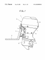
As shoWn in FIG. 1, outboard motor 2 is mounted to a
transom beam 4 of a hull 3 by means of a bracket 5.
Outboard motor 2 has a drive shaft housing 6 Which extends
vertically in the rear of bracket 5 and is of a holloW body
overally having a horiZontal section of a fusiform. Formed
over drive shaft housing 6 is an engine holder 7, on Which
engine 1 lidded With a cover la is mounted. A gear casing 8
is linked under drive shaft housing 6. This gear case 8
above operation and effects of the seventh or eighth con
?guration.
In accordance With the tenth feature of the invention, the
system, includes: a means Wherein upper limits of the
recommended number of engine revolutions or upper limits
of the recommended load are preset for the running-in
process based on the total operating time, or based on a
rotatably supports a propeller shaft having a propeller 9
distance-related value and Whereby the number of engine
directed horiZontally to the rear.
revolutions or load is judged to exceed the upper limit; and
a means for performing the predetermined indication (With
a lamp or buZZer) When the upper limit is exceeded. As a
result, the running-in process of the engine, Which Was
dif?cult to manage, can be simply and exactly effected
Without any cost, thus making it possible to improve the
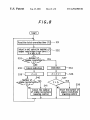
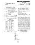
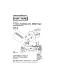
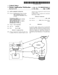
The engine control system in accordance With this
embodiment uses an electronically controlled fuel injection
system, and the engine management system is also con?g
15
durability of the product.
the system having the above tenth feature, further includes
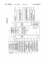
sure inside the surge tank (intake pressure sensor 18), the
a control means for loWering the number of engine revolu
atmospheric pressure (atmospheric pressure sensor 19), the
engine temperature (cooling Water temperature sensor 20),
and the intake temperature (intake temperature sensor 21)
tions When the engine continues to be run for more than a
certain period of time With the speed or load exceeding the
predetermined value. Therefore, in addition to the action and
effect of the above tenth con?guration, this control means
can gradually loWer the number of engine revolutions by
are detected by corresponding sensors so that the detected
25
results are input to control unit 11 through an input circuit
12. If engine 1 is a tWo-cycle engine, signals from an oil ?oW
sWitch 22a and from an oil level sWitch 22b are supplied to
control unit 11. If engine 1 is of a four-cycle type, a signal
from oil pressure sWitch 22c is input into control unit 11.
In accordance With the tWelfth feature of the invention, in
the system having the above eleventh, When the engine has
In control unit 11, a CPU (central processing unit) 13
including a microcomputer, RAM and ROM, calculates the
intake amount based on the data, and performs additional
compensations for the intake amount, thereafter calculates
the optimal injected amount of fuel, Which is in turn output
continued to run at an number of engine revolutions loWer
than the predetermined rate for canceling the number of
engine revolutions loWering control, to thereby meet the
predetermined condition, for example, When the engine is
has been run for a time longer the set time, the system judges
that the operator has recogniZed the running-in process and
returned the throttle, and cancels the number of engine
revolutions loWering control.
perform engine management, the rotational speed of engine
1 (crank angle sensor 16), the degree of the throttle valve
opening (throttle valve opening sensor 17), the intake pres
In accordance With the eleventh feature of the invention,
performing the ignition cutting, controlling the phase lag
and/or injection.
ured of sensors, an electronic control unit 11, indicators, etc.
As shoWn in FIG. 2, in order to control fuel injection and
35
to a fuel injector 10 via an output circuit 14. Fuel injector 10
injects an optimal amount of fuel corresponding to the intake
amount by duty control.
Control unit 11, in addition to the above fuel injection
BRIEF DESCRIPTION OF THE DRAWINGS
control, performs Warning detection, storage of the operating
FIG. 1 is an illustrative vieW shoWing an engine of the
embodiment in accordance With the invention;
FIG. 2 is a block diagram of the control system of an
from control unit 11 are supplied to indicators 23 such as
time and control of the running-in process. Other outputs
monitor lamps, buZZer, tachometer etc., an air amount
adjusting actuators 24 such as stepping motors, solenoid
valves etc., a fuel pump relay 25, and an ignition device 26
including an ignition coil 26a, etc.
engine of the embodiment;
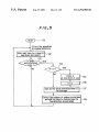
FIG. 3 is a ?oWchart for illustrating the control of
embodiment 1;
45
embodiment 1;
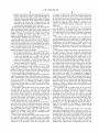
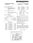
FIG. 5 is a ?oWchart for illustrating the running time
accumulation control in accordance With embodiment 2;
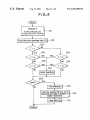
FIG. 6 is a ?oWchart for illustrating the control of
Weighted summed time in accordance With embodiment 2;
FIG. 7 is a chart for illustrating the control during the
supplied to a poWer circuit 29.
Control unit 11, in addition to ROM (read only memory)
and RAM (random access memory) for storing the programs
to be effected by CPU 13 and the determined data, may have
running-in process; and
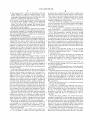
FIG. 8 is a ?oWchart for illustrating the control of the
55
running-in process.
after removable of the poWer source. The examples of such
memory include an EEPROM (electrically erasable pro
grammable ROM) Which may have the program content
The embodiments of the invention Will hereinafter be
described in detail With reference to the accompanying
erased and neW information implanted therein and can retain
data during the poWer being off.
draWings.
FIG. 1 is an illustrative vieW shoWing an outboard motor
2 having an electronically controlled fuel injection type
engine (internal-combustion engine) 1 in accordance With
control system of the engine 1.
a memory 30 Which stores data Without being affected by the
battery poWer source. This memory 30 may be a storage
capable of retaining data by virtue of a backup poWer source
DESCRIPTION OF THE PREFERRED
EMBODIMENTS
the embodiment. FIG. 2 is a block diagram shoWing the
Control unit 11 also has a communication interface 28
through Which signals such as operating instructions etc., are
transferred via a transceiver 27 from the helm arranged in
front of the operator, and thereby the signals are input into
CPU 13. PoWer from the battery and/or the magneto is
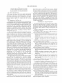
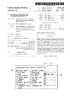
FIG. 4 is an illustrative diagram shoWing data storage in
65
NoW, overall scheme of the control of the engine man
agement system in accordance With embodiment 1 Will be
described.
1) The system stores the operating time at the occurrence of
a Warning and the operating time at the cancellation of the
Warning.
US 6,294,988 B1
7
8
2) The system stores a variety of information about the
unoperated for a long period of time after a Warning of oil
engine (number of engine revolutions, degree of the
level, oil pressure and/or overheat and hence offer a proper
advice based on the aforementioned diverse pieces of data.
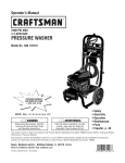
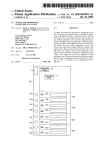
Next, FIG. 3 shoWs a control ?oWchart for a speci?c
Warning management of embodiment 1 and FIG. 4 shoWs an
throttle opening, boost pressure, Wall temperature, intake
temperature, atmospheric pressure, etc.) from the occur
rence of a Warning to the end of the Warning.
3) The system overWrites the information concerning 1) and
2) so that the latest, multiple number of data, depending
example of information storage scheme.
As shoWn in FIG. 4, Warnings [1] to [n] correspond to
overrev, oil pressure, oil level, oil ?oW, battery undervoltage,
upon the storage capacity, of Warnings can alWays be
stored. The system also changes the storing interval
(sampling time) of the diverse information of 2) depend
ing upon the storage capacity.
overheat and the like, respectively. Variables x1 to xn, M1 to
10 Mn are de?ned as folloWs:
‘x1 to xn’ correspond to Warnings [1] to [n] and take a
4) The system stores the number of occurrences of Warnings.
value of 0 (xi=0 (i=1, . . . , n) before the corresponding event
The above stored contents can be displayed on the service
tool (personal computer etc.) through communication net
Work When the engine failure is repaired at the checkup site
such as automobile dealer etc., Whereby it is to provide the
15
occurs and a value of 1 (xi=1) during the event is occurring.
M1 to Mn correspond to memory blocks for storing
Warning information. There are a plural number of (for
example, three) memory blocks for storing each kind of
information, and the information of each Warning is stored
folloWing effects and advantages.
Actually, from the operating time at the occurrence of a
Warning and the cancellation of the Warning, the duration of
or overWritten into the cell in the next block When the
the Warning can be knoWn so that it is possible to determine
Whether the user took a quick action to the Warning or
continued to run the engine at a loW speed Without taking
Warning is cancelled, so that the latest plural number of data
can remain. In preparation for a sudden shutdoWn of the
poWer source, Whenever each Warning is stored, the memory
block is stored into the aforementioned memory 30 (see FIG.
2) Which is able to keep the data even after the deactivation
any action. Further, since the sites in the engine Which might
possibly be damaged can be located from the types of
Warnings and the engine information recorded during the
running of the engine, it is possible to offer advice about the
user’s action (Written in the user’s manual etc.,) upon the
of the poWer source.
25
As shoWn in the ?oWchart in FIG. 3, in the Warning
management of embodiment 1, When the poWer is activated,
Warning or Whether the user’s action Was proper or not, as
x1 to xn are initialiZed (x1=0, x2=0, . . . , xn=0) so as that
Well as to facilitate early detection and replacement of
no Warning is given.
The process of storing the information of Warnings such
consumable and/or degraded parts.
As a practical example, if a Warning of overheat occurred
as time of the occurrence and cancellation of each of
When the total operating time Was at 30 hrs. 12 min., and Was
canceled at 30 hrs. 14 min., the record can be understood as
Warnings [0] through [n] is effected, folloWing the How
(partial ?oW) Within each of the regions {B1} to {En} in
a temporal (about tWo minutes in this case) cooling perfor
FIG. 3.
In the determining process of the partial ?oW {B1}, it is
mance degradation (due to air suction by excessive rise of
the PT (PoWer Trim and Tilt), due to temporal clogging of
35
is occurring (Step (S) 1).
the Water inlet port With a polyvinyl ?lm or other object or
If Warning [1] is occurring (Slzyes), it is checked Which
due to other reasons), or as that the user took a proper action
upon the Warning.
memory block, M1, M2 or M3, the data is to be Written in
(S2a, S2b).
In the case Where a Warning of overheat occurs at 500 hrs.
12 min. and is cancelled at 501 hrs. 32 min., this situation
indicates that the engine Was operated at a loW speed for a
If the data should be Written into memory block M1 (S2a:
yes), the partial ?oW process {A} in the ?oWchart of FIG. 3
long time (about 1.5 hours in this case). Therefore, it is
highly probable that the engine has been damaged. In
addition, in vieW of the occurrence of the Warning after a
long use, this situation should be recogniZed such that
determined Whether Warning [1] (of, for example, overrev)
45
clogging of the cooling Water path With salt etc., degradation
of Water pump, thermostat, piston, cylinder, harness and
other parts, should be checked for replacement. Moreover,
since the diverse pieces of information about the engine
is effected. On the other hand, if the data should not be
Written into memory block M1 but should be Written into
memory block M2 (S2bzyes), or should be Written into
memory block M3 (S2b1no), the same process as in {A} is
performed and the data is stored into memory block M2 or
M3, respectively.
Here, in the partial How {A}, it is checked ?rst Whether
x1 is equal to 0 (x1=0) (S3).
have been stored from the occurrence of the Warning to the
If x1=0 and a Warning occurs (S3:yes), each piece of
end of it, it is also possible to predict Whether the engine has
been damaged, from the highest Wall temperature and the
number of engine revolutions during the above 1.5 hours.
information is Written into the cell at the time of occurrence
in FIG. 4. Speci?cally, the total operating time is stored as
the time of occurrence (S341), and each piece of engine
information is stored as the information at the time of
The dealer can offer advice to the user about the usage and
maintenance, based on the types of Warnings With their
numbers of occurrence. For example, if an engine is found
to have had many overrev, it is possible for the dealer to
55
occurrence (S3b), and then x1 is incremented by 1 (x1=x1
+1) (S3c).
On the other hand, if S3=no, x=1, Which means that a
Warning is occurring (that is, the Warning once occurred has
advise the user about Whether a proper propeller is selected
and/or Whether the engine is operated in a right manner
not been cancelled yet), so that the total operating time is
(about the Way of raising the PTT and other operation).
stored (overWritten as the time of cancellation) (S3a) Then
the engine information is stored (overWritten as the infor
mation at the time of cancellation) (S3e). This storing is
repeated or updated (overWritten) until the Warning is can
If the engine is found to have had an increased number of
over-Warnings, it is determined that there is a chance of
degradation of the cooling system performance, so that
checkup as Well as replacement of consumable and degraded
parts can be performed.
Other than the above, upon troubles such as engine burn
etc., it is possible to con?rm that the engine has been
celled so that the latest information can be stored.
65
Accordingly, since the latest information is overWritten
and stored until the Warning is cancelled, the latest infor
mation data Will remain as the data at the time of cancella
US 6,294,988 B1
9
10
tion even if the power is abruptly shut doWn. Here, the
deactivation of the power is determined as the cancellation.
NeXt> the memory block hhthher at which the data Was
Stored is Stored ihto the memory (S4)-
In contrast to this, embodiment 2 of the invention com
putos the total operating time in the following manner;
(1) The system computes the sum of the time during Which
engine 1 runs. The system is one shoWn in FIG. 3. In this
Since the memory block number is stored at S4 even if an
abrupt poWer shutdoWn occurs, X1 to Xn Will be set into the
number of engine revolutions detector (during running).
case, time is summed up When the signal is input from the
cancelled state (X1 to Xn=0) When the poWer is activated
neXt. Every time the operation is started, the memory
(2) In parallel, the sum of time classi?ed according to the
engine’s speed during running is recorded.
number is loaded (S5) so that the memory locations in the
memory block neXt to the loaded memory block are set to be 10
accessible for storage (S6). Here, in this embodiment, since
three memory blocks for each Warning are provided, the data
is stored into block M1 after the storage into block M3 (S7).
(rpm)’ at 2000 to 3000 (rpm) at 3000 to 4000 (rpm)> at 4000
to 5000 (rpm) at 5000 to 6000 (rpm)> and at 6000 (rpm) or
That is, the memory block is sWitched in the sequential order
of 1_>2_>3_>1_
For example, the time is classi?ed, according to number
.
.
of engme revolutlons’ at 0 to 1000 (rpm)’ at 1000 to 2000
above'
_
_
_
_
_
15 (3) The time of operation is classi?ed and stored according
On the other hand, if the judgment is negative at S1, it is
judged Whether X1 is equal to 0 (X1=()) (59)' When X1=1
(S9:no), this indicates that the Warning had occurred up to
the previous judgment and is cancelled at this time. In this
case, X1 is initialiZed so that X1=0 (S10), and M1 is
to the ehgihe’s hhthher of ehgihe revohltiohs ahd the
engine’s load. The load on the engine is calibrated based
Oh the degree of the throttle Opening, the boost, etc» With
relation to the number of engine revolutions. Stored
eXample of the time of operation is shoWn in Table 1.
TABLE 1
Number of engine revolutions
00-1000
Throttle opening
Opening
10002000
20003000
30004000
40005000
5000
6000
6000
0—20%
20—40%
40—60%
60-80%
80—100%
incremented by 1 (M1=M1+1) so that the memory block
(4) The operating time is summed and stored. When the total
number istvaried (S11 t0_ $13)- That iS, the memory blOek iS
SWltehed 1h the seqhehtlal 0rde_r 0f_1'>2'>3'>1~
_
time has reached the set time of maintenance or the set
time of replacement of consumable and degraded parts,
Accordingly, until the Warning is canceled, the data is
thiS Will be indicated by lighting of a lamp (LPD), buzzer
sound and/or on a display device (LCD etc.).
40 (5) For some maintenance items, consumable and degraded
overWritten into the same memory block.
The above description is made as to the process for
Warning [1], after the partial ?oW {B1} is ?nished, a similar
partial ?oW {B2} of the process of storing the information
parts, judgement from only the operating time is not
as to occurrence and cancellation of Warning [2] is effected
in the same manner as the processing of the above partial
?oW {B1}. When this process is completed, the process for
enough good> so that the Operatmg tune 1S Cahbrated by
giving a Weight to respective operating time (by thulti'
plying a eOef?eieIlt) based on the number of engine
Warning [3] is effected by the partial ?oW {B3}. In this Way, 45
revolutions, load (the degree of throttle opening, boost)
a similar How is effected for each Warning [1] to [n] While
and/or operated temperature. When the thus calibrated
variables Xn and Mn are varied.
time has reached the set time, the item Will be displayed.
Thus, as ShOWn in FIG- 4, the Warning iHfOIIIIatiOIl at the
latest, the second to the last and the third to last can remain
for each Warhihg-
_
_
Next; embodhheht 2 W111 be desenbed _
In this embodiment 2, the operating time is stored so as to
inform the user or others of the timing of maintenance and
(6) In addition to (5) above, for the items Which Will degrade
not only from running but also from being left, the
50
passage of time in addition to the operating time also
needs to be considered for the time calibration. When
either of the tW0 has ?rst reaehed the Set time, the item
related should be displayed.
the timing of replacement of consumable and degraded
(7) When the interval for maintenance and the interval for
elements.
55 replacement change depending upon the total operating
Differing from the tWo-Wheel and four-Wheel vehicles, an
time, the set value is varied depending upon the operating
outboard motor has no Wheel, and hence has no Way to
detect the absolute distance of movement. Though it has a
time.
_
_
speed meter Which is operated making use of Water pressure
Next an example of the engme management _system _1n
during movement, this speed meter produces ?uctuations in
accordance Wlth embotilment 2_ Wm be desttnhed wlth
measurement, depending upon the pressure detecting 60 reference to the application to indication of the timing of oil
position, the hull shape, forWard/backWard movement and
turning and other factors, so that it cannot measure the total
ehahglhg- FIGS- 5 and 6 Shows the Operatloh hOW of thls
ehgihe thahagetheht
distance of movement. Therefore, in general, an hour meter
In this ease, as ShOWh in Table 2 belOW, the summed time
is used in place. This hour meter typically computes the sum
(A to G) for each range of number of engine revolutions is
of the time during Which the main poWer source (the ignition 65 multiplied by a Weighting coef?cient (Which is previously
sWitch) is turned on, and sums the time When the hour meter
is energiZed even if engine 1 produces no rotation.
determined), and the Weighted time is summed up to com
pute a summation X.
US 6,294,988 B1
11
12
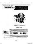
revolutions range (computing the summed time A to G for
each number of engine revolutions range (see Table 2)), and
TABLE 2
the results are stored (S18). Then the operation returns to
S12.
Number of engine
revolutions range
Summed time
Coe?icient
0-1000 (rpm)
1000-2000
A
B
a
b
Axa
Bxb
2000-3000
C
c
Cxc
3000-4000
D
d
Dxd
4000-5000
E
e
Exe
5000-6000
F
f
Fxf
6000-
G
g
Gxg
Total
10
The indication of the timing of oil changing is performed
folloWing the ?oWchart shoWn in FIG. 6. That is, the
summed operating time A to G computed for each number
of engine revolutions range in accordance With the ?oWchart
shoWn in FIG. 5, is given a Weight according to Table 2
above, and the thus Weighted values are summed up to
compute a total X (S21). For example, X=A><a+B><b+
C><c+ . . . G><g is computed.
X
Next, by reading the total operating time (Y), it is deter
mined Whether this total operating time (Y) has reached the
In this embodiment 2, When the above summation X
15
reaches the set value or more, the user is informed of the
timing of the engine oil to be changed, by lighting an oil
change sign or displaying it on a liquid crystal display (in a
stepwise manner). When the user recognizes the indication
and performs the canceling operation and/or replacement,
the system detects the completion of this process and clears
the display and storage and restart summing the time for the
next indication about the timing for changing oil. Since the
degradation of the oil, even With the same total operating
time, varies depending upon the frequency of use, load, use
temperature and use time, the timing of oil changing is
not reached the set time y, the set values x1 and z1 are used
(S23 and S25). If the total operating time has reached, the set
values x2 and z2 are used (S24 and S26).
20
X has not reached x1 or x2, the time Z reaches z1 or z2 (S24
or S26zyes), an indication of oil changing is output (S27).
This indication is performed by means of a symbol mark
25
Subsequently, after the output of the indication, the user
more reliable and exact manner compared to the conven
30
the summed time A to G for each number of engine
revolutions range and time Z are cleared (S28 to S31). If
these values need to be used for other control, they can be
stored in another memory.
If the cancellation has not been done, the indication
35
continues to be output (S28zno).
The indication for the oil changing timing does not need
revolutions range.
to be done at short intervals, so that the indication can be
made during the loW speed mode, or during the CPU
It should be noted that the indication of the oil changing
timing does not need to be made at short intervals so that the
indication can be made during the loW speed mode, or
during the CPU operating time such as When the main poWer
operating time such as When the main poWer is turned on.
40
is turned on.
Next, the operation ?oWs Will be described.
As shoWn in the ?oWchart in FIG. 5, computation of the
total time for each number of engine revolutions range is
(H=0).
50
on the presence or absence of the input from the number of
a rotational input (from the engine’s running) (S13). If there
55
60
after shipment (start) is recorded.
When the engine is in operation (S13:yes) and When the
engine has been already started at that time (S14:no), the
total operating time (Y) is summed up and the sum is stored
(S17). Then the number of engine revolutions is detected
and the time is added up for each detected number of engine
As stated above, an outboard motor has no total distance
meter, so that it needs a record of the use time for achieving
liable to be run erroneously in a high load range Without
making any running-in process. On the other hand, the
rotational input) (S13:yes), it is judged Whether H is equal
to 0, that is, Whether the operation is at starting stage (S14).
If the engine has is just started operating, the time ‘Z’ When
the operation is started is stored at the beginning (S15), and
variable H is set into 1 (S16). That is, the use starting time
Next, embodiment 3 Will be described.
This embodiment 3 is to indicate and manage the running
in process, making use of the memory of the total operating
time.
a proper running-in process. Further, in general, an outboard
motor is used With the throttle opened to a high degree (or
in a high load range), more often compared to the tWo-Wheel
and four-Wheel vehicles. Therefore, the outboard motor is
engine revolutions detector, it is determined Whether there is
is no rotational input, the engine remains unoperated so that
the operation returns to S12.
On the other hand, if the engine is operated (there is a
In the above embodiment 2, a speci?c example of indi
cation of the engine oil changing timing Was described.
Other than this, supply or replacement of various elements
such as gear oil, engine oil ?lter, Water pump impeller, etc.,
can be indicated in a similar manner.
45
commenced after the activation of the poWer source such as
battery (S11). In this case, a variable H is initialized at zero
For storing the time after the poWer activation, a unit time
is added to time ‘Z’ at regular intervals (S12). Then, based
lamp, liquid crystal display or the like.
recognizes the timing for changing oil and performs the
canceling operation (for example, turn the cancellation
sWitch on) (S28zyes), the indication output is stopped and
Without memorizing the previous time of changing oil, in a
(b) The interval for the ?rst oil changing is set shorter.
(c) Taking into account the degradation from a prolonged
time of being left, the display of oil changing is indicated
by selecting the earlier one from the operating time and
the time of being left.
When the total X reaches x1 or x2 (S23 or S24zyes), an
indication of oil changing is output (S27). Even if the total
indicated
This con?guration
also taking
alloWs
into the
account
user the
to manage
folloWing
oil (a)
changing
to
tional con?guration.
(a) Giving Weights based on the used number of engine
set time y. Based on this result, the set value for oil changing
is altered (S22). That is, if the total operating time (Y) has
engine of tWo-Wheel or four-Wheel vehicle has a transmis
sion device. So, if it is run in a high load range, the speed
of the vehicle becomes higher than required, so that there is
little chance that the engine is continued to be run in the high
load range.
As shoWn in FIG. 7, depending upon the running time (A
to D) from the start of use of the engine, the upper limit of
the recommended number of engine revolutions and the
65
upper limit of the recommended engine load (substituted by
or calibrated from the degree of the throttle opening, boost
pressure, air amount, or the like) are set, and if the engine is
US 6,294,988 B1
13
14
run exceeding the predetermined value, an indicator (lamp,
LCD etc.) and/or buZZer is used for Warning. Alternatively,
stored at the occurrence of a Warning or from the occurrence
of a Warning to the end of the Warning, from the diverse
information about the engine during the occurrence of a
if the engine continues to run exceeding the set value for a
injection are controlled so as to gradually loWer the number
Warning, the judgment of the presence of damage to the
engine can be made easily and the handling (repair,
of engine revolutions to thereby promote the user running-in
replacement, etc.) can be simpli?ed.
time longer than the set period of time, the ignition and
In accordance With the third feature of the invention, since
the operating time When a Warning about the engine
process.
Further, When the number of engine revolutions is gradu
occurred, the operating time When the Warning is cancelled,
ally decreased so as to remind the user of the running-in
process and the user recogniZes the running-in process and
10
returns the throttle so that the engine continues to run at a
loWer speed than the set value Without the necessity of the
speed loWering control (ignition cutting, phase lag, injection
cutting, etc.), the speed loWering control Will be cancelled.
This con?guration is to prevent engine’s inability to avoid
15
and the various pieces of information about the engine at the
occurrence of the Warning or from the occurrence of the
Warning to the end of the Warning are stored in memory, it
is possible to estimate the user’s action and the duration of
the Warning from the time of occurrence of the Warning and
the time of the end of the Warning. Further, from the diverse
information about the engine during the occurrence of a
emergency due to the running-in process. In this case,
hoWever, if the engine of the boat continues to be driven for
Warning, the judgment of the presence of damage to the
sailing exceeding the set value for a certain time, the speed
improved.
engine and the handling (repair, replacement, etc.) can be
loWering control Will be performed again.
In accordance With the fourth feature of the invention,
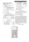
In the management control of embodiment 3, as shoWn in
the ?oWchart in FIG. 8, variable Z is set into 0 (Z=0) When
since the numbers of occurrences of various Warnings are
stored in memory, it is possible to offer advice about the Way
the operation is started. First, the total operating time (Y) at
of manipulating the boat, propeller matching, maintenance
present is read out (S31) so as to select the set value X (X=a,
etc., if the engine has had certain kinds of Warnings many
b, c or d (see FIG. 7)) for number of engine revolutions in
order to perform indication and the number of engine
25
times.
In accordance With the ?fth feature of the invention, since
various information can be transferred to a display device
revolutions loWering control (S32). If the number of engine
through communication netWork so that the stored pieces of
information can be displayed on the display device, this
revolutions is greater than the set value X (S33zyes), an
indication (lamp, LCD, etc.) indicates that the number of
con?guration provides for simplifying the layout of the
engine revolutions exceeds the recommended number of
engine revolutions (S34). On the other hand, if the number
of engine revolutions is equal to or loWer than the set value
management unit and the display device, in addition to the
operation and effectiveness of the above ?rst through fourth
features.
In accordance With the sixth feature of the invention, since
the system has a means for storing the operating time
(S33: no), the indication is cancelled (S35).
If the number of engine revolutions exceeds the set value,
variable Z is incremented by 1 (i.e., Z=Z+1) (S36). When Z
engine revolutions Was judged to exceed the set value in
classi?ed according to number of engine revolutions and/or
engine load, and manages the engine based on the stored
time, the timing of maintenance and replacement of con
succession, the number of engine revolutions loWering con
sumable parts, Which Were dif?cult to manage can be knoWn
trol is performed (S37 to S38).
and hence can be performed easily and Without any cost.
In accordance With the seventh feature of the invention,
the system includes a storing means Whereby the operating
time to be stored is given a Weight according to the prede
has become greater than Z1 (Z>Z1) after the number of
35
When the speed is loWer than the set value, variable Z is
initialiZed into Zero (Z=0) (S39). When the number of
engine revolutions becomes loWer by ‘e’ than the set value
X for number of engine revolutions loWering control, the
system judges that the pilot has recogniZed the number of
engine revolutions loWering control and returned the
throttle, and cancels the loWering control (S40 and S41).
termined running condition of the engine, and the operating
time is summed up separately based on the number of engine
revolutions and based on the engine load so that the sum
45
In embodiment 3 above, the control based on the upper
limit of the recommended number of engine revolutions Was
described, but a similar control can be performed based on
the upper limit of the recommended load (the load calculated
item (such as the timing of maintenance, the timing of
replacement of consumable and/or degraded parts) is indi
cated (by lighting of a lamp, buZZer sound, LCD display
etc.). Thus, since the exhaustion and degradation not only
from the degree of the throttle opening, boost pressure,
intake air amount, etc.).
The preferred examples of the invention have been illus
trated in the description of the above embodiments, but the
depends on the time of operation but also depends on the
number of engine revolutions, load and temperature, this
con?guration of giving Weights enhance the precision of the
timing of replacement.
present invention should not be limited to these. For
example, the engines applied to the invention include those
mations are stored. In this system, When the stored operating
time reaches a set value, the corresponding management
55
for Water-surface boats as Well as under-Water boats.
As has been described, in accordance With the ?rst feature
of the invention, since the operating time When a Warning
about the engine occurred and the operating time When the
In accordance With the eighth feature of the invention,
When either the time obtained by giving Weights to the
operating time classi?ed according to number of engine
revolutions and engine load, or the engine’s use time
(including the time of being left other than the operating
time), ?rst reaches the set value, the predetermined man
Warning Was cancelled are stored in memory, it is possible
to estimate the user’s action and the duration of the Warning
from the time of occurrence of the Warning and the time of
agement item (the timing of replacement) is indicated. Thus,
the timing of replacement can be changed taking into
the end of the Warning. Accordingly, the judgment of the
account not only the operating time but also the time of
presence of damage to the engine can be made easily and the
being left. As a result, this con?guration provides enhance
ment of the precision of the timing of replacement in
handling (repair, replacement, etc.) can be simpli?ed.
In accordance With the second feature of the invention,
since the various pieces of information about the engine are
65
addition to the above operation and effects of the seventh
con?guration.
US 6,294,988 B1
15
16
In accordance With the ninth feature of the invention,
concerning management items of Which the interval for
maintenance or replacement varies depending upon the total
operating time, the set value is sWitched based on the total
Weighted operating reaches said predetermined value before
said total Weighted operating time.
5. The method according to claim 1, Wherein said prede
termined value for said predetermined management item
varies depending upon the total Weighted operating time of
operating time. Accordingly, it is possible to vary the timing
of replacement of items, of Which the interval for replace
said engine.
ment varies, such as engine oil etc., based on the total
6. The method according to claim 4, Wherein said prede
termined value for said predetermined management item
varies depending upon the total Weighted operating time of
operating time. Because, for example, engine oil needs to be
changed after a shorter interval, for the ?rst time. Thus, this
con?guration provides the above effect in addition to the
above operation and effects of the seventh or eighth con
said engine.
7. A system for providing a predetermined management
item relating to an engine comprising:
?guration.
In accordance With the tenth feature of the invention, the
system, includes: a means Wherein upper limits of the
recommended number of engine revolutions or upper limits
of the recommended load are preset for the running-in
means for storing a Weighted operating time for each of a
plurality of running conditions of said engine, said
15
Weighted operating times being a product of a respec
tive predetermined Weighting coefficient and a respec
process based on the total operating time, or based on a
distance-related value and Whereby the number of engine
tive operating time;
revolutions or load is judged to exceed the upper limit; and
a means for performing the predetermined indication (With
a lamp or buZZer) When the upper limit is exceeded. As a
means for summing said Weighting operating times to
produce a total Weighted operating time; and
means for indicating a corresponding predetermined man
result, the running-in process of the engine, Which Was
dif?cult to mange, can be simply and exactly effected
Without any cost, thus making it possible to improve the
durability of the product.
agement item When said total Weighting operating time
25
In accordance With the eleventh feature of the invention,
the system having the above tenth feature, further includes
condition of said engine includes one or more of the fol
a control means for loWering the number of engine revolu
loWing: the number of engine revolutions, the throttle open
ing of said engine and the operating temperature of said
tions When the engine continues to be run for more than a
certain period of time With the speed or load exceeding the
predetermined value. Therefore, in addition to the action and
effect of the above tenth con?guration, this control means
can gradually loWer the number of engine revolutions by
performing the ignition cutting, controlling the phase lag
and/or injection.
engine.
10. The means according to claim 7, Wherein the prede
termined management item is indicated if a total non
35
In accordance With the tWelfth feature of the invention, in
the system having the above eleventh, When the engine has
continued to run at an number of engine revolutions loWer
11. The means according to claim 7, Wherein said prede
termined value for said predetermined management item
varies depending upon the total Weighted operating time of
12. The means according to claim 10, Wherein said
engine revolutions loWering control, to thereby meet the
predetermined condition, for example, When the engine is
predetermined value for said predetermined management
item varies depending upon the total Weighted operating
time of said engine.
has been run for a time longer the set time, the system judges
What is claimed is:
1. A method for providing a predetermined management
Weighted operating reaches said predetermined value before
said total Weighted operating time.
said engine.
than the predetermined rate for canceling the number of
that the operator has recogniZed the running-in process and
returned the throttle, and cancels the number of engine
revolutions loWering control.
reaches a predetermined value.
8. The means according to claim 7, Wherein the running
condition includes the number of revolutions of said engine.
9. The means according to claim 7, Wherein the running
13. An engine management system for an engine, com
45
prising:
means for storing data relating to said engine Wherein an
upper limit of a recommended number of engine revo
item relating to an engine, comprising the steps of:
storing a Weighted operating time for each of a plurality
of running conditions of said engine, said Weighted
operating times being a product of a respective prede
termined Weighting coef?cient and a respective oper
lutions or an upper limit of a recommended load are
preset in said means for storing for a running-in process
of said engine based on a total operating time of said
engine, or based on a distance-related value of said
engine and Whereby the number of engine revolutions
or load of said engine is judged to exceed said upper
ating time;
limit;
summing said Weighting operating times to produce a
total Weighted operating time; and
indicating a corresponding predetermined management
item When said total Weighting operating time reaches
a predetermined value.
2. The method according to claim 1, Wherein the running
condition includes the number of revolutions of said engine.
3. The method according to claim 1, Wherein the running
means for performing a predetermined indication When
said upper limit is exceeded; and
control means for loWering the number of engine revo
lutions When the engine continues to be run for more
than a certain period of time With a speed or load
exceeding a predetermined value.
14. The engine management system according to claim
condition of said engine includes one or more of the fol
13, farther including means for canceling said control means
loWing: the number of engine revolutions, the throttle open
ing of said engine and the operating temperature of said
for loWering When the engine has continued to run at a
engine.
4. The method according to claim 1, Wherein the prede
termined management item is indicated if a total non
number of engine revolutions loWer than a predetermined
65 rate.