1
This document is available at HTTP://WWW.FALCOM.DE .
FALCOM
A2D-3,A2D-3JP3,
A3D &A3DJP3
(Programming Manual)
Version 1.17
A2D-3, A2D-3JP3, A3D & A3DJP3 PROGRAMMING MANUAL
VERSION 1.17
Contents
0
INTRODUCTION............................................................................................... 3
0.1
0.2
0.3
SECURITY ....................................................................................................................................... 3
SAFETY STANDARDS .............................................................................................................. 6
RELATED DOCUMENTS.................................................................................................................... 6
1
GENERAL DESCRIPTION ............................................................................. 8
1.1
1.2
1.3
1.4
1.5
1.6
1.7
SUPPORTED GPS PROTOCOLS BY THE GPS RECEIVERS µ-BLOX, JP3, AND JP2 ..................... 9
SUMMARY SCHEMATICS A2D-3 AND A2D-3JP3....................................................................... 11
SUMMARY SCHEMATICS A3D AND A3DJP3 .............................................................................. 12
DETAILED START-UP INFORMATION ............................................................................................ 13
DOWNLOADING EXECUTABLE FILES ............................................................................................ 14
UPGRADING PREVIOUS MONITOR VERSIONS ............................................................................... 15
MON186 COMMANDS ................................................................................................................. 16
2
PROGRAMMING GUIDE ............................................................................. 22
2.1
2.2
2.3
2.4
2.5
2.6
2.7
SERIAL SUPPORT FUNCTIONS....................................................................................................... 22
ENVIRONMENT SUPPORT FUNCTIONS .......................................................................................... 26
TIME AND DATE SUPPORT FUNCTIONS ....................................................................................... 27
GSM SUPPORT FUNCTIONS ......................................................................................................... 29
GPS SUPPORT FUNCTIONS ........................................................................................................... 31
FLASH FUNCTIONS ..................................................................................................................... 33
FUNCTIONS FOR IO SIGNALS ...................................................................................................... 35
3
MON186 SYSTEM SERVICES .................................................................... 37
3.1
3.2
3.3
3.4
3.5
3.6
3.7
3.8
3.9
SERIAL SUPPORT FUNCTIONS....................................................................................................... 37
ENVIRONMENT SUPPORT FUNCTIONS .......................................................................................... 38
TIME AND DATE SUPPORT FUNCTIONS ....................................................................................... 39
MEMORY MANAGEMENT FUNCTIONS ......................................................................................... 40
PROCESS MANAGEMENT FUNCTIONS ......................................................................................... 41
CONSOLE CHARACTER INPUT AND OUTPUT FUNCTIONS .......................................................... 42
FILE FUNCTIONS........................................................................................................................... 43
AUXILIARY IO FUNCTIONS ......................................................................................................... 44
MISCELLANEOUS FUNCTIONS ...................................................................................................... 44
4
HARDWARE SUPPORT................................................................................ 45
4.1
4.2
A2D-3 AND A2D-3JP3 HARDWARE SETTINGS .......................................................................... 45
A3D AND A3DJP3 HARDWARE SETTINGS................................................................................. 48
5
DEBUG INTERFACE.................................................................................... 51
6
TECHNICAL DATA ...................................................................................... 53
This document is a property of FALCOM GmbH and may not be copied or circulated without
permission.
Page 1
A2D-3, A2D-3JP3, A3D & A3DJP3 PROGRAMMING MANUAL
VERSION 1.17
Version history
Version number
1.00
1.02
1.03
1.04
1.10
1.11,1.12
1.13
1.14
1.15
1.16
1.17
Author
R. Georgi
R. Georgi
R. Georgi
R. Georgi
R. Georgi
R. Georgi
R. Georgi
B. Kirchner
R. Georgi
R. Georgi
B. Kirchner
Changes
Initial version
Additional hardware information
Schematic A2(D)-3
Chapter 3./4. Scope changed
Additional functions (LIBA1 Release 1.02 for A2D-3)
Update and bugfixes
Update Hardware revision A2D-3REV6
Update A3(D), additional functions (LIBA2 R 1.12)
Update Hardware description of A3D (Page 46)
Bug fixes
- Update gps_init() for JP3
- Supported GPS protocols added
- Differences between the provided GPS receivers
- Related documents added
Registered Trade Mark: Windows and Hyperterminal are
registered trade marks of Microsoft Corporation.
This document is a property of FALCOM GmbH and may not be copied or circulated without
permission.
Page 2
A2D-3, A2D-3JP3, A3D & A3DJP3 PROGRAMMING MANUAL
VERSION 1.17
0 Introduction
This manual is focussed on the GSM data solutions of the FALCOM A2D3, A2D-3JP3, A3D and A3DJP3 series from FALCOM GmbH. It contains
information about programming purposes of the integrated controller of the
A2D-3, A2D-3JP3, A3D and A3DJP3. Please consult also the user manuals
of the FALCOM A2D embedded GSM module and the FALCOM A2D-1
GSM modem and phone. It does not contain special information about the
GSM related accessories, as there are the dial-handset, the hands free set,
the external battery pack and the mobile data terminals, which are also sold
by FALCOM.
Information furnished herein by FALCOM GmbH is believed to be
accurate and reliable. However, no responsibility is assumed for its use.
Also the information contained herein is subject to change without
notice.
Users are advised to proceed quickly to the “Security” chapter and read
the hints carefully.
0.1 Security
IMPORTANT FOR THE EFFICIENT AND SAFE OPERATION OF
YOUR GSM MODEM READ THIS INFORMATION BEFORE USE!
Your GSM modem is one of the most exciting and innovative electronic
products ever have developed. With it you can stay in contact with your
office, your home, emergency services, and others, wherever service is
provided.
GENERAL
Your modem utilises the GSM standard for cellular technology. GSM is
a newer radio frequency (« RF ») technology than the current FM
technology that has been used for radio communications for decades. The
GSM standard has been established for use in the European community
and elsewhere.
Your modem is actually a low power radio transmitter and receiver. It
sends out and receives radio frequency energy. When you use your
modem, the cellular system handling your calls controls both the radio
frequency and the power level of your cellular modem.
EXPOSURE TO RF ENERGY
There has been some public concern about possible health effects of
using GSM modem. Although research on health effects from RF energy
has focused for many years on the current RF technology, scientists have
begun research regarding newer radio technologies, such as GSM. After
existing research had been reviewed, and after compliance to all
This document is a property of FALCOM GmbH and may not be copied or circulated without
permission.
Page 3
A2D-3, A2D-3JP3, A3D & A3DJP3 PROGRAMMING MANUAL
VERSION 1.17
applicable safety standards had been tested, it has been concluded that
the product is fit for use.
If you are concerned about exposure to RF energy there are things you
can do to minimise exposure. Obviously, limiting the duration of your
calls will reduce your exposure to RF energy. In addition, you can reduce
RF exposure by operating your cellular modem efficiently by following
the below guidelines.
EFFICIENT MODEM OPERATION
For your modem to operate at the lowest power level, consistent with
satisfactory call quality :
If your modem has an extendible antenna, extend it fully. Some models
allow you to place a call with the antenna retracted. However your
modem operates more efficiently with the antenna fully extended.
Do not hold the antenna when the modem is « IN USE ». Holding the
antenna affects call quality and may cause the modem to operate at a
higher power level than needed.
ANTENNA CARE AND REPLACEMENT
Do not use the modem with a damaged antenna. If a damaged antenna
comes into contact with the skin, a minor burn may result. Replace a
damaged antenna immediately. Consult your manual to see if you may
change the antenna yourself. If so, use only a manufacturer-approved
antenna. Otherwise, have your antenna repaired by a qualified technician.
Use only the supplied or approved antenna. Unauthorised antennas,
modifications or attachments could damage the modem and may
contravene local RF emission regulations or invalidate type approval.
DRIVING
Check the laws and regulations on the use of cellular devices in the area
where you drive. Always obey them. Also, when using your modem
while driving, please : give full attention to driving, pull off the road and
park before making or answering a call if driving conditions so require.
When applications are prepared for mobile use they should fulfil roadsafety instructions of the current law!
ELECTRONIC DEVICES
Most electronic equipment, for example in hospitals and motor vehicles
is shielded from RF energy. However RF energy may affect some
malfunctioning or improperly shielded electronic equipment.
VEHICLE ELECTRONIC EQUIPMENT
Check your vehicle manufacturer’s representative to determine if any
electronic equipment on board is adequately shielded from RF energy.
This document is a property of FALCOM GmbH and may not be copied or circulated without
permission.
Page 4
A2D-3, A2D-3JP3, A3D & A3DJP3 PROGRAMMING MANUAL
VERSION 1.17
MEDICAL ELECTRONIC EQUIPMENT
Consult the manufacturer of any personal medical devices (such as
pacemakers, hearing aids, etc...) to determine if they are adequately
shielded from external RF energy.
Turn your modem OFF in health care facilities when any regulations
posted in the area instruct you to do so. Hospitals or health care facilities
may be using RF monitoring equipment.
AIRCRAFT
Turn your modem OFF before boarding any aircraft.
Use it on the ground only with crew permission.
Do not use in the air.
To prevent possible interference with aircraft systems, Federal Aviation
Administration (FAA) regulations require you to have permission from a
crew member to use your modem while the plane is on the ground. To
prevent interference with cellular systems, local RF regulations prohibit
using your modem whilst airborne.
CHILDREN
Do not allow children to play with your modem. It is no toy. Children
could hurt themselves or others (by poking themselves or others in the
eye with the antenna, for example). Children could damage the modem,
or make calls that increase your modem bills.
BLASTING AREAS
To avoid interfering with blasting operations, turn your unit OFF when
in a « blasting area » or in areas posted : « turn off two-way radio ».
Construction crew often use remote control RF devices to set off
explosives.
POTENTIALLY EXPLOSIVE ATMOSPHERES
Turn your modem OFF when in any area with a potentially explosive
atmosphere. It is rare, but your modem or its accessories could generate
sparks. Sparks in such areas could cause an explosion or fire resulting in
bodily injury or even death.
Areas with a potentially explosive atmosphere are often, but not always,
clearly marked. They include fuelling areas such as petrol stations ;
below decks on boats ; fuel or chemical transfer or storage facilities ; and
areas where the air contains chemicals or particles, such as grain, dust, or
metal powders.
Do not transport or store flammable gas, liquid or explosives, in the
compartment of your vehicle which contains your modem or accessories.
Before using your modem in a vehicle powered by liquefied petroleum
gas (such as propane or butane) ensure that the vehicle complies with the
This document is a property of FALCOM GmbH and may not be copied or circulated without
permission.
Page 5
A2D-3, A2D-3JP3, A3D & A3DJP3 PROGRAMMING MANUAL
VERSION 1.17
relevant fire and safety regulations of the country in which the vehicle is
to be used.
NON-IONISING RADIATION
As with other mobile radio transmitting equipment, users are advised that
for satisfactory operation and for the safety of personnel, it is
recommended that no part of the human body be allowed to come too
close to the antenna during operation of the equipment.
The radio equipment shall be connected to the antenna via a nonradiating 50Ohm coaxial cable.
The antenna shall be mounted in such a position that no part of the
human body will normally rest close to any part of the antenna. It is also
recommended to use the equipment not close to medical devices as for
example hearing aids and pacemakers.
0.2 SAFETY STANDARDS
THIS CELLULAR MODEM COMPLIES WITH ALL APPLICABLE
RF SAFETY STANDARDS.
This cellular modem meets the standards and recommendations for the
protection of public exposure to RF electromagnetic energy established
by governmental bodies and other qualified organisations, such as the
following :
¾ Directives of the European Community, Directorate General V in
Matters of Radio Frequency Electromagnetic Energy.
0.3 Related documents
¾ ETSI GSM 07.05: “Use of Data Terminal Equipment - Data Circuit terminating
Equipment interface for Short Message Service and Cell Broadcast Service“
¾ ETSI GSM 07.07: “AT command set for GSM Mobile Equipment”
¾ ITU-T V.25ter: “Serial asynchronous automatic dialling and control”
The below related documents could be found on: www.falcom.de > Service >
Manuals
¾ “a2dman.pdf”: AT command set
¾ Zod_dg.pdf: User manual for GPS protocols of the GPS receiver JP2
¾ SiRFmessages.pdf:
Input/Output
Receivers with SiRFstarIIe-chip-set.
Messages
for
Falcom
GPS-
This document is a property of FALCOM GmbH and may not be copied or circulated without
permission.
Page 6
A2D-3, A2D-3JP3, A3D & A3DJP3 PROGRAMMING MANUAL
VERSION 1.17
¾ A2-3dev.zip: Sources (examples) and libraries for programming FALCOM
A2D-3, FALCOM A2D-3JP3, FALCOM A3D and FALCOM A3DJP3. It also
includes a “getting started” document for the developer-KIT.
This document is a property of FALCOM GmbH and may not be copied or circulated without
permission.
Page 7
A2D-3, A2D-3JP3, A3D & A3DJP3 PROGRAMMING MANUAL
VERSION 1.17
1 General Description
MON186 is the operating system for FALCOM A2D-3, A2D-3JP3, A3D
and A3DJP3 with the Am186ES controller.
MON186 is a basic monitor. It supports download of executable images to
ROM or RAM, and rudimentary debugging. For developers just getting
started, however, MON186 running on FALCOM A2D-3, A2D-3JP3, A3D
and A3DJP3 modems provides a powerful tool to allow quick prototyping
and benchmarking of simple algorithms, before a major investment is made
in x86 development tools. Its minimal DOS emulator allows the developer
to download and run small .EXE files which were developed and tested
using standard compilers on a PC running DOS.
NOTE! THIS DESCRIPTION APPLIES TO BOARDS OPERATING AT
FACTORY DEFAULT SETTINGS. PLEASE SEE "DETAILED
STARTUP INFORMATION" BELOW IF THIS PROCEDURE DOES
NOT WORK FOR YOU.
The GSM modems FALCOM A3D and FALCOM A3DJP3 can contain the
following components:
Feature
GSM Core
GPS Core (option)
CPU Core
Flash/ SRAM/ EEPROM/ RTC
MMC Card support (option)
External Serial Interfaces
IO’s
Hands-Free-Kit (option)
Backup Battery
Communication via Internet
(option)
Hardware Extensions Support
A3D
WM2C2
FALCOM JP21)
AM186ES
1MB/ 256KB/ 4KB/Yes
Yes
3 RS232/ 1RS485
8digital IO’s or
6 digital IO’s + 2 analogue
inputs
Integrated (Full Duplex,
Echo-Cancellation)
1200mAh Li-Ion +
Yes (i-Chip, ConnectOne)
A3DJP3
WM2C2
JP32)
AM186ES
1MB/ 256KB/ 4KB/Yes
Yes
3 RS232/ 1RS485
8digital IO’s or
6 digital IO’s + 2 analogue
inputs
Integrated (Full Duplex,
Echo-Cancellation)
1200mAh Li-Ion +
Yes (i-Chip, ConnectOne)
Yes
(System
Bus
Yes
(System
Bus
Connector)
Connector)
Power Management
Enhanced (Co-Processor)
Enhanced (Co-Processor)
Voltage Range
8-36 V DC
8-36 V DC
Cradle
Yes (same like A2D-3)
Yes (same like A2D-3)
DOS like Monitor
Yes
Yes
1) FALCOM JP2: Chipset CONEXANT (For further information about the
GPS protocols, please refer to the related document „Zod_dg.pdf“)
This document is a property of FALCOM GmbH and may not be copied or circulated without
permission.
Page 8
A2D-3, A2D-3JP3, A3D & A3DJP3 PROGRAMMING MANUAL
VERSION 1.17
2) FALCOM JP3: Chipset SiRF starII (For further information about the
GPS protocols, please refer to the related document „SiRFmessages.pdf“)
The GSM modems FALCOM A2D-3 and FALCOM A2D-3JP3 can contain
the following components:
Feature
A2D-3
A2D-3JP3
GSM Core
GPS Core (option)
CPU Core
Flash/SRAM/EEPROM/RTC
External Serial Interfaces
IO’s
Power Management
Voltage Range
Cradle
DOS like Monitor
WM2C
µ-blox3)
AM186ES
IMB/256KB/4KB/Yes
2 RS232
4 digital IO’s
Enhanced (Co-Processor)
10,8...31,2 VDC
Yes
Yes
WM2C
JP34)
AM186ES
IMB/256KB/4KB/Yes
2 RS232
4 digital IO’s
Enhanced (Co-Processor)
10,8...31,2 VDC
Yes
Yes
3) µ-blox: Chipset SiRF starI (For further information about the GPS
protocols, please refer to the related document „SiRFmessages.pdf“)
4) JP3: Chipset SiRF starII (For further information about the GPS
protocols, please refer to the related document „SiRFmessages.pdf“)
1.1 Supported GPS protocols by the GPS receivers µ-Blox, JP3, and
JP2
µ -Blox and JP3
(Chipset from SiRF)
GPGGA
GPGSV
GPGSA
GPRMC
GPVTG
GPGLL
JP2
(Chipset from Conexant)
GPGGA
GPGSV
GPGSA
GPRMC
GPVTG
PRWIZCH
This document is a property of FALCOM GmbH and may not be copied or circulated without
permission.
Page 9
A2D-3, A2D-3JP3, A3D & A3DJP3 PROGRAMMING MANUAL
VERSION 1.17
ATTENTION: The Libraries (refer to A2-3dev.zip)
provided by Falcom GmbH support the NMEA GPS
protocols of µ-blox GPS MS1, FALCOM JP2 and
FALCOM JP3. An example of GPS init (gps.c) could be
found in the A2-3dev.zip.
By using other libraries (customer’s libraries) please
refer to the corresponding manual (SiRFmessages.pdf or
Zod_dg.pdf).
This document is a property of FALCOM GmbH and may not be copied or circulated without
permission.
Page 10
A2D-3, A2D-3JP3, A3D & A3DJP3 PROGRAMMING MANUAL
VERSION 1.17
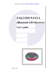
1.2 Summary schematics A2D-3 and A2D-3JP3
For a quick overview please have a look at the schematic of the FALCOM
A2D-3 and A2D-3JP3. Detailed information you will find in chapter 6
„Technical Data“.
INTERFACE B (DB15)
INTERFACE C (RJ45)
INTERNAL (GSM)
INTERNAL (GPS)5) /DEBUG (DB9)
COM1
COM2
COM3
COM4
5) GPS embedded into A2D-3: µ- blox (Chipset SiRF starI)
GPS embedded into A2D-3JP3: JP3 (Chipset SiRF starII)
This document is a property of FALCOM GmbH and may not be copied or circulated without
permission.
Page 11
A2D-3, A2D-3JP3, A3D & A3DJP3 PROGRAMMING MANUAL
VERSION 1.17
1.3 Summary schematics A3D and A3DJP3
For a quick overview please have a look at the schematic of the A3D and
A3DJP3. Detailed information you will find in chapter 6 „Technical Data“.
Controller
AM186ES-25
Memory Devices
COM2
RTC
I2 C
256K RAM
1M FLASH
COM1
Power Panagemenet and
I/O controler
System Bus
EEPROM
UART 1
16C752B
Power Supply
Wakeup Logic
Extension Connector
INTERFACE (DB9) RS232
INTERFACE (RJ45) RS232
INTERNAL (GSM)
INTERNAL (GPS)6)
INTERFACE (DB15) RS232
INTERFACE (DB15) RS485
GSM
COM3
GPS
COM4
UART 1
16C752B
COM5
COM6
COM1
COM2
COM3
COM4
COM5
COM6
6) GPS embedded into A3D: JP2 (Chipset CONEXANT)
GPS embedded into A3DJP3: JP3 (Chipset SiRF starII)
This document is a property of FALCOM GmbH and may not be copied or circulated without
permission.
Page 12
A2D-3, A2D-3JP3, A3D & A3DJP3 PROGRAMMING MANUAL
VERSION 1.17
1.4 Detailed start-up information
Set up your PC terminal program for 9600 Baud, at 8 bits per character, no
parity and one stop bit. Set the terminal program flow control to hardware
flow control. Connect the supplied serial cable of the PC to the FALCOM
A2D-3, A2D-3JP3, A3D or A3DJP3
When the modem is reset, the 2 LEDs will go on. This first LED pattern will
hold for four seconds. After four seconds MON186 will start a default
modem application or display its sign on screen to the terminal and updating
the LED display. At this point, you can press '?' followed by <ENTER> for
MON186's help screen. When power is supplied, the initial LED pattern
indicates that MON186 is waiting for an ‘@‘ character to be received from
the terminal. If it receives an ‘@‘, it will automatically adjust to the baud
rate of the ‘@‘ character and display the MON186 welcome message and
prompt. If it receives any character other than an ‘@‘ it will restart the
terminal check and let the user try again to press an ‘@‘.
If the user does not press an ‘@‘ during the initial LED pattern (nominally
four seconds), MON186's next action depends on whether the user has
installed a start-up program in the flash or not. If the user has used the ‘W‘
command to store an application program in the flash and the set "auto-run"
variable to mark it for running at start-up time, then that DOS program will
be executed. Otherwise, MON186 will display the welcome message and
prompt with the standard baud rate settings. If the baud rate does not match
that one of the terminal, the user will see nothing or garbled characters. (See
the „Downloading EXE files" sections for information about installing user
programs. )
At the factory, the baud rate is set to 9600 and the setting is 8N1. You can
change this default by setting the COM "baud rate" variable on a common
value.
The automatic baud rate detection is very useful in the following
circumstances:
¾ If a user program is installed, but the user wishes to invoke the monitor
instead.
¾ If the programmed baud rate does not match the terminal baud rate.
¾ If the programmed CPU speed does not match the actual CPU speed.
(The bit clock is divided down from the CPU clock.)
¾ If the user does not want to wait 4 seconds for booting of the monitor
The automatic baud rate detection is designed to detect baud rates from
1200 to 115200, but how well it works depends on the CPU type and speed.
The algorithm may also fail at higher baud rates if you run the CPU at
slower frequencies than the default 18.432 MHz.
This document is a property of FALCOM GmbH and may not be copied or circulated without
permission.
Page 13
A2D-3, A2D-3JP3, A3D & A3DJP3 PROGRAMMING MANUAL
VERSION 1.17
MON186 supports downloading of Intel extended hex files into RAM or
ROM. The hex file should contain type 2 extended address records, which
specify the load address in the 1MB address range and the last record in the
file should be a type 1 EOF record.
A file which is being downloaded to RAM for execution should be located
between 410h and the start of the monitor data at the end of the RAM, and a
file which is being downloaded to ROM for execution should be located
between the start of the ROM and F0000h. The monitor ‘I‘ command will
show the size and location of the free RAM, and some information about the
size and location of the flash ROM.
It is impermissible for the file to have some sections download to RAM and
others download to ROM, because MON186 relocates itself to some RAM
locations while running. MON186 will report a range error on the download
of such a file.
If you are downloading into ROM, you should first make sure that the target
download area is empty by using the ‘X‘ command to erase the flash
sectors. Unless you are storing multiple programs into flash, the easiest way
to do this is to use ‘XZ‘ to erase all the application sectors.
There is no specific command to download hex files. Simply start
transferring with your terminal program in “ASCII“ or "raw ASCII" mode.
MON186 will echo the first record as it receives it, but when it parses it and
determines that it is a hex file record, it will switch into a file transfer mode.
The type 1 EOF record at the end of the file will switch back to command
mode.
If an error is encountered during the download, an error message will be
printed, and MON186 will stay in download mode until it receives an
Escape character (1Bh), at which time it will print a more detailed error
message and then return to command mode.
1.5 Downloading executable files
MON186 can download and run DOS executable files, enabling customers
to use affordable, readily available, and familiar PC-based compilers and
assemblers to develop initial test and benchmarking code. MON186
provides a minimal subset of DOS int 21h functionality, which is fully
described in the section, "MON186 system services" chapter 3. Most
compilers are capable of generating EXE files which work within this
environment, as long as the user does not use library functions which
require file-based I/O.
Unlike some prior versions, MON186 V3.37 does not support direct
downloading of EXE files. It supports AMD LPD extensions to the Intel hex
file format instead and a supplied conversion program will convert EXE
This document is a property of FALCOM GmbH and may not be copied or circulated without
permission.
Page 14
A2D-3, A2D-3JP3, A3D & A3DJP3 PROGRAMMING MANUAL
VERSION 1.17
files into this extended hex file format. There are several reasons for this
change:
(1) Unlike hex files, exe files do not have error checking
(2) Some terminal programs, e.g. Hyperteminal® which comes with
Windows® xx, will not transmit binary data unchanged.
(3) The added overhead of transferring a hex file is mitigated
by the fact that MON186 allows baud rates up to 115200.
(4) The hex files can be stored to Flash (using the ‘W‘ command) and later
moved to RAM and executed (using the ‘L‘ command).
To convert your EXE file into a HEX file, use the MAKEHEX utility
supplied on this archive in the TOOL subdirectory. For example, to convert
FOOBAR.EXE into FOOBAR.HEX, simply type MAKEHEX FOOBAR
(assuming MAKEHEX.EXE is in your path).
Once you have converted your EXE file, simply download it to MON186 as
described in the previous section. Once it is downloaded, you can set
parameters for the program (if it expects a command line) with the ‘N‘
command, and then start execution with the ‘G‘ command.
Alternatively, use the ‘W‘ command before you start downloading the file,
to program it into flash. Since flash is non-volatile, the program can then be
run multiple times, even after power has been cycled.
1.6 Upgrading previous monitor versions
(1) Use the 'XZ' command to erase all application flash sectors.
(2) Upload A2MON3xx.HEX, the upgrade file, to the board. It is not
necessary to type any command to do this, the MON186 automatically
recognises a file download when it sees the colon which starts the file.
(3) Use the 'G' command to go to the new monitor, which is running out of
user flash ROM space. This will automatically go to the correct
address.
(4) Press in the first 4 seconds an '@' to establish communication with the
new monitor. You are now running out of the application ROM based
copy of the monitor.
(5) Type 'Z' <enter> to initiate the upgrade. You will be asked if this
is really what you want to do. Answer 'Y' to perform the upgrade, but
do not do this if your power is not stable, or if little children are
near the On/Off button. If the upgrade is aborted before it finishes
you may need to send your board back to factory to have the flash
reprogrammed.
This document is a property of FALCOM GmbH and may not be copied or circulated without
permission.
Page 15
A2D-3, A2D-3JP3, A3D & A3DJP3 PROGRAMMING MANUAL
VERSION 1.17
(6) Your monitor is now upgraded, but you are still running out of the
application ROM copy of the monitor. To run out of the new boot
copy of the monitor press '@‘<ENTER> then within 4 seconds
‘@’<ENTER> again to establish communication with the boot copy
of the monitor.
(7) You can now use the 'XZ' command to remove the application copy of
the monitor, and then download any desired hex file to application
ROM.
1.7 MON186 commands
The first step in understanding how to use MON186 commands is to
understand the command parameters. Different commands take different
parameters but these parameters are very commonly used:
byte
-- 1 or 2 hexadecimal digits
WORD
-- 1-4 hexadecimal digits
DECIMAL
-- 1-9 decimal digits
ADDRESS
-- An address may be entered in typical x86 segment:
offset format, e.g. F800:0 to refer to the base of the monitor, or a
LINEAR address may be entered as 5 hex digits, e.g. F8000. If the
linear address approach is used, MON186 treats the first 4 digits as the
segment, and the last digit as the offset. Most commands which do not
alter memory also support SHORT addresses. A short address is
where only the offset is specified (between 1 and 4 hex digits). The
current value of the DS register is implicitly used for the segment.
Commands which alter memory require a full address.
RANGE
-- An address range may be specified in two different
ways, either as <address> <space> <address>, where the address of
the start of the range and the address immediately after the end of the
range are specified, or as <address> L <length>, where the address of
the start of the range and the length of the range are explicitly
specified. The following commands are identical, and dump 1024
bytes starting at 16K:
D 400:0 400:400
D 0:4000 400:400
D 04000 L 400
d04000l400
As the last command shows, spaces only matter where the parser would
have trouble distinguishing the end of one number from the start of the next
one, and all commands may be entered in upper or lower case.
This document is a property of FALCOM GmbH and may not be copied or circulated without
permission.
Page 16
A2D-3, A2D-3JP3, A3D & A3DJP3 PROGRAMMING MANUAL
LIST
VERSION 1.17
-A list is a collection of bytes. Each byte may be specified
with one or two hex digits, with the bytes separated by spaces, and
ASCII data may be specified in single or double quotes. The following
command will place an ASCII string, complete with carriage return
and two line feeds, at 16K:
E 04000 "This is a quoted string" 0D A,0A
Note that (other than the mandatory 5 digits for a linear address) numbers
do not require leading zeros. Also note that commas are optional.
They may be used instead of or in conjunction with spaces.
Fat characters
command name and syntax (commands must be
completed and executed with <ENTER> key)
Angle brackets <> indicate required parameters.
Square brackets [] indicate optional parameters.
Vertical bar
| indicates the user should choose one of the parameters
<Break>
When MON186 receives an RS232 break (usually invoked
by pressing Alt-B or Ctrl-Break on the terminal application) it will break
into the debugger. This is useful in some cases when your application
appears 'hung' -- you can find out where it is executing. Note, however, that
<Break> can also be used to debug MON186 itself, and you should be
careful how many times you press it without pressing "G" to continue
program execution. Please note that too many breaks will cause a stack
overflow within MON186 itself. This break detection will be allowed or
restricted depending on the setting of the BOOT environment parameter.
B <address>
Sets a breakpoint by saving the value at a location, and
then inserting an int 3 instruction (CCh) at that location. Only one
breakpoint is active at a time -- setting one removes previous breakpoints.
Breakpoints may only be set in RAM, not in ROM. When the int 3 at the
breakpoint is executed, the code at the breakpoint is automatically restored.
At this point, you may set another breakpoint if you desire and use the G or
T commands to continue execution.
C <range> <address> Compares two memory ranges. Each differing byte
will be displayed on a single line as:
<addr in range> <byte in range> <comparison byte> <comparison address>
D[WA] [range]
Dumps a memory range, in hexadecimal
bytes/words and/or ASCII. If the range is not specified, it will dump 128
bytes starting where the most recent dump command has been finished.
E <address> [list]
Enter memory. If the list (at least one byte) is
specified, the entire list will be stored in memory at <address>. If no list is
specified, the command will prompt for entry of a list of bytes at
incrementing addresses. When all data has been entered, respond to the
This document is a property of FALCOM GmbH and may not be copied or circulated without
permission.
Page 17
A2D-3, A2D-3JP3, A3D & A3DJP3 PROGRAMMING MANUAL
VERSION 1.17
prompt with a single dot ‘.‘ on a line or with the escape key this function
can be finished.
F <range> <list>
Fills a memory range with a list of bytes. The
entire range is filled, and the list is replicated as many times as it takes to fill
it. The size of the list does not need to fit evenly in the range: the last copy
of the list is truncated to fit.
G [=[address]] "Go", e.g. start execution. If an address is given, it will be
stored in CS:IP before execution is starting. The equal sign is permitted for
compatibility with DOS DEBUG.
I[W[word]]
The "Info/Input" command by itself will show information
about the system. A typical screen shoot you will find below. The line
os release listen the running monitor version. The line system time shows
the current date and time. The line “remote port” lists the current monitor
connection with the corresponding serial settings. The “Rom/Ram/Free”
size displays the code size, the data size of the monitor itself and the
available free ram size. The line flash device shows the detected flash
device and the size of the flash. The last line shows the current monitor code
base start, the boot monitor code base start and flash sectors usable for
storing programs.
OS release:
A3x86 Monitor V3.44(FIFO) released 25.01.2002
System time:
Thu 27.Jun.2002 11.39.46
Remote port:
COM1 9500,8N1,H
Rom/Ram/Free size: 087E0 03730 3C4B0
Flash device:
29LV800B 1024KB
Mon/Boot/App base: F0000 F0000 - 8000 9000 A000 B000 C000 D000 E000
For input ports ‘I‘ followed by a word will input from a byte-wide port and
display the results, and ‘IW‘ followed by a word will input from a wordwide port and display the results.
J
The J command causes the automatic baud rate detection to be
invoked. Once you have entered this command, you may change the
terminal's baud rate. Once you are set up properly, simply press "a" to reestablish connection with the monitor. Note that automatic baud rate
detection may not be reliable at baud rates which are relatively high to the
CPU frequency and bus width. At a CPU frequency of 18.432MHz, the
Am186ES parts can reliably detect 115200 kBaud.
L[G] [decimal] The “Load“ command loads a previously stored hex file
from flash to RAM. If no parameters are given, a list of currently stored
programs is displayed. If a decimal number is given, the corresponding
program is copied from flash to RAM. Programs are loaded to flash using
the W command, and may be made bootable with the "AutoRun" setting.
The ‘LG‘ command is equivalent to the ‘L‘ command immediately followed
by a ‘G‘ command, e.g. load and run the program.
This document is a property of FALCOM GmbH and may not be copied or circulated without
permission.
Page 18
A2D-3, A2D-3JP3, A3D & A3DJP3 PROGRAMMING MANUAL
LG 1
L
VERSION 1.17
-- loads programm 1 in RAM and starts execution
-- list installed programms
M <range> <address>
Moves a block of memory from one address
to another. Overlapping blocks are handled correctly. The following
command sequence shows how the monitor can be executed out of RAM:
M F0000 L F000 00400 -- moves monitor to base of RAM
G 00400
-- starts execution
I
-- shows new monitor CS and free memory
N <arguments>
In DOS DEBUG, this command names the COM
or EXE file to load or save, and also gives command line arguments.
MON186 has no knowledge of the file name, so only requires command line
arguments (if needed by the program). We recommend you to design your
test program so that it does not rely on command line arguments as it is easy
to forget to use the ‘N‘ command.
O[W] <word> <byte>|<word>
Outputs the second parameter (byte or word) to the port given in the first
parameter. Use ‘OW‘ for word-wide outputs, ‘O‘ for byte-wide outputs.
P[ABCX] [VariableName DecimalValue|String Value]
Sets, shows or clears permanent environment parameters. The monitor
stores these values in a 32 kBit serial eeprom. Use ‘PC‘ to clear all
environment parameter at once. Use ‘PX’ to perform an internal cleanup
and compress operation. Use ‘P VariableName‘ to clear a specific setting.
For its own configuration MON186 uses the following variables:
BOOT = cpuspeed,autorun,feature
cpuspeed -- This defines the speed of the CPU to the monitor. This is
required for correct default baud rate set up and to correct internal
timer tick correctly, which is used by benchmark programs and also
governs the speed of the LED patterns.
autorun -- When this is non-zero, it selects which EXE program to load
from the flash and run at boot time. A value beetween 8000 - F000
starts directly a program downloaded to this address in the flash.A
value greater than 0 starts a EXE program loaded to the flash with the
‘W‘ command.
feature -- This defines a special string with following meaning. When the
character ‘L‘ is defined, the monitor will use the LEDs to show
current status. When this is not set, the monitor will not change the
LEDs. When the character ‘B‘ is defined, the monitor enter itself after
receiving a break on the serial port. With the character ‘Q’ you can
skip the autobaud test on the COM1 on every boot operation. To
perform a check and cleanup operation of the environment settings on
every boot process you can set the character ‘E’.
This document is a property of FALCOM GmbH and may not be copied or circulated without
permission.
Page 19
A2D-3, A2D-3JP3, A3D & A3DJP3 PROGRAMMING MANUAL
VERSION 1.17
COM1 = baudrate[,mode,muxvalue,handshake][,buffer size]
COM2 = baudrate[,mode,muxvalue,handshake][,buffer size]
baudrate -- Sets the default baudrate for the serial port (1200 - 115200). The
detection of the baudrate at startup overwrites this setting und the
monitor uses the detected value instead.
mode -- Sets the default line setting for the serial port
( 7E1,7O1,8N1,8E1,8O1 ).
handshake - Sets the used flow control of serial operation. That means with
‘X‘ the monitor uses XonXoff software flow control and with ‘H‘ the
monitor uses RtsCts hardware flow control.
buffer size - Sets the size of the buffer for the serial port. The default value
is 1024 Byte and can be set from 256 .. 8192 Byte.
P BOOT “18432000,1,l”
P COM1 “57600,8N1,0,H”
-- set autorun after boot to programm 1
-- set COM1 to 57600 baud, 8N1 with handshake
R [RegisterName | ("F" FlagName)]
The "Register" command with no parameters will display the current state
of all registers and flags. ‘R‘ can also be used to set the value of any
register or flag bit:
To examine a register: R AX
This will print the current value of the AX register and prompt you for
a new value.
To change a register without examining it: R AX 5000
This will change the value of AX to 5000h.
To examine the flags: R F
This will print the current flag values, and prompt you for a two letter
code to change them. Flag names are the same as DOS debug uses.
Don't worry if you get the flag name wrong, MON186 will show you
the names it expects.
To change a flag without examining it: R F DN
This will set the direction flag, so the direction is now "down".
NOTE: As discussed previously, in most situations, spaces are optional.
These commands could be entered as RAX, RAX5000, RF, and
RFDN, respectively.
S <range> <list>
„Search“ a given range for a list of bytes. The
starting address of each occurrence of the list within the range is displayed.
There will be no display if the list is not found within the range.
T [=address] [word] This command uses the x86 trap flag to trace
execution. Unlike breakpoints, traces may be performed in ROM as well as
This document is a property of FALCOM GmbH and may not be copied or circulated without
permission.
Page 20
A2D-3, A2D-3JP3, A3D & A3DJP3 PROGRAMMING MANUAL
VERSION 1.17
RAM. An optional starting address may be used to set CS:IP before the
trace starts, and an optional number of steps to trace may be entered as well.
The default is 1 step.
W [file name] [base] The “Write“ command initiates a download of a
hex file (generated by running the host program MAKEHEX on a DOS
executable) to the flash. The file name is given so that the program can be
identified later if multiple programs are stored in the flash. Programs are
stored starting at the base segment reference of the flash. Use the ‘L‘
command later to move a program into RAM for execution, or use the
"AutoRun" setting to cause the monitor to load and run a program at boot
time.
W test-program
-- store program test-program
... upload an application hexfile as text, ascii or raw file ...
X <sector number> | Z
The "eXterminate" command will erase one
of the sectors in the application area of the flash or, if ‘XZ‘ is given, will
erase all of them. The ‘I‘ command can be used to retrieve information
about the sectoring of the flash part. Use 0 to refer to the first sector, 1 to the
next one, etc.
U [hh.mm.ss] [dd.mm.yyyy]
The “U“ command sets the current system time and date to the real time
clock or shows the current value.
Z
The “Z“ command upgrades the boot monitor. It may be issued
under two circumstances, either from a monitor which is running at the
upgrade location (normally E0000h, but depends on flash type), to upgrade
the boot monitor in the same flash part, or from a monitor which is running
at the boot monitor location (F0000h) to replace a dead monitor in a
different flash part (on boards which support a CS switch from one flash to
another).
This document is a property of FALCOM GmbH and may not be copied or circulated without
permission.
Page 21
A2D-3, A2D-3JP3, A3D & A3DJP3 PROGRAMMING MANUAL
VERSION 1.17
2 Programming guide
We choose Paradigm C++ 5.00.025 as programming environment for the
FALCOM A2D-3, A2D-3JP3, A3D and A3DJP3. That package includes all
necessary tools to build application for the FALCOM A2D-3, A2D-3JP3,
A3D and A3DJP3. The standard „C“ functions are contained in the standard
libraries of Paradigm C++. The different programming environment for the
hardware related parts of the FALCOM A2D-3, A2D-3JP3, A3D and
A3DJP3 are included in an additional library. That library „LIBA2.LIB“
contains hardware related serial, date, time and environment functions and
the syntax of those additional functions are listed below. For an overview of
the Paradigm C++ standard function please look at the online helps or try to
refer to it in a programming training course.
2.1 Serial support functions
The functions init_stream(), ComGetch(), ComPutch(), ComGets(),
ComPuts(), ComString(), ComStringCR(), ComGet() can be used to
communicate with those serial devices. The functions ComGetConfig(),
ComSetConfig(), ComLine() should be used for reading the current state of
the com port or changing the com port configuration. Please note that after
every function which returns the state of the com port (LineState), an
existing error condition will be cleared.
Parameter definitions:
#define PORT_COM1
#define PORT_COM2
#define PORT_COM3
#define PORT_COM4
#define PORT_COM5
#define PORT_COM6
0
1
2
3
4
5
// control values for set in ComLine()
#define LINE_SET
#define LINE_CLEAR
#define LINE_FLUSH
#define LINE_BREAK
#define LINE_UPDATE
#define LINE_RESET
#define LINE_MASK
#define LINE_DCD
#define LINE_DSR
#define LINE_CTS
#define LINE_DTR
#define LINE_RTS
#define LINE_RI
0x8000
0x0000
0x4000
0x2000
0x1000
0x0800
0x00FF
0x0080
0x0020
0x0010
0x0008
0x0004
0x0002
This document is a property of FALCOM GmbH and may not be copied or circulated without
permission.
Page 22
A2D-3, A2D-3JP3, A3D & A3DJP3 PROGRAMMING MANUAL
#define LINE_DEVICE
0x0001
// return values for line state
#define LINE_STS_MASK
#define LINE_ERROR
#define LINE_TRNS_NOTREADY
#define LINE_RECV_BREAK
#define LINE_TRNS_BLOCKED
#define LINE_RECV_FRAME
#define LINE_RECV_PARITY
#define LINE_RECV_OVER
#define LINE_RECV_READY
#define LINE_MASK
#define LINE_DCD
#define LINE_DSR
#define LINE_CTS
#define LINE_DTR
#define LINE_RTS
#define LINE_RI
#define LINE_DEVICE
0xFF00
0x8000
0x4000
0x2000
0x1000
0x0800
0x0400
0x0200
0x0100
0x00FF
0x0080
0x0020
0x0010
0x0008
0x0004
0x0002
0x0001
VERSION 1.17
// serial parameter values for config in ComGetConfig(), ComSetConfig()
#define MODE_BIT_MASK
0x0003
#define MODE_BIT_5
0x0000
#define MODE_BIT_6
0x0001
#define MODE_BIT_7
0x0002
#define MODE_BIT_8
0x0003
#define MODE_STOP_MASK
0x0004
#define MODE_STOP_1
0x0000
#define MODE_STOP_2
0x0004
#define MODE_PAR_MASK
0x0018
#define MODE_PAR_NONE
0x0000
#define MODE_PAR_ODD
0x0008
#define MODE_PAR_EVEN
0x0018
#define MODE_BAUD_MASK
0x00E0
#define MODE_BAUD_1200
0x0000
#define MODE_BAUD_2400
0x0020
#define MODE_BAUD_4800
0x0040
#define MODE_BAUD_9600
0x0060
#define MODE_BAUD_19200
0x0080
#define MODE_BAUD_38400
0x00A0
#define MODE_BAUD_57600
0x00C0
#define MODE_BAUD_115200
0x00E0
// flow control values for config
#define MODE_FLOW_MASK
#define MODE_FLOW_H
#define MODE_FLOW_X
#define MODE_MUX_MASK
0x0300
0x0100
0x0200
0x0C00
This document is a property of FALCOM GmbH and may not be copied or circulated without
permission.
Page 23
A2D-3, A2D-3JP3, A3D & A3DJP3 PROGRAMMING MANUAL
VERSION 1.17
// mux control values for config (only for A1-3)
#define MODE_MUX_DB9
0x0000
#define MODE_MUX_GPS
0x0400
#define MODE_MUX_GSM
0x0800
#define MODE_MUX_WS
0x0C00
Definition of the com_stream structure:
typedef struct com_stream {
ulong timemark;
uchar port;
uint line;
uint state;
int count;
uchar p[400];
};
Initialize com_stream structure to zero and set the port number in it:
void init_stream(struct com_stream *d,char port);
Parameter
com_stream *d
Char
port
com_stream structure
ComPort
Get Parameter of com port:
uint ComGetConfig( byte com,uint *config,uint *timeout );
Parameter
Result
byte
uint*
uint*
uint
com
config
timeout
line
ComPort
ComConfig, see MODE_xxx parameter
Timeout
LineState, see LINE_xxx parameter
Set Parameter of com port. Communication speeds grater then 57600 in
Applications are not recommended:
uint ComSetConfig( byte com,uint config,uint time );
Parameter
Result
byte
uint
uint
uint
com
config
time
line
ComPort
ComConfig, see MODE_xxx parameter
Timeout
LineState, see LINE_xxx parameter
Get a character from com port:
uint ComGetch( byte com );
Parameter
Result
byte
uint
com
line
ComPort
LineState (HighByte) and InputData (LowByte)
Put a character to com port:
This document is a property of FALCOM GmbH and may not be copied or circulated without
permission.
Page 24
A2D-3, A2D-3JP3, A3D & A3DJP3 PROGRAMMING MANUAL
VERSION 1.17
uint ComPutch( byte com,byte xch );
Parameter
Result
byte
byte
uint
com
xch
line
ComPort
OutputData
LineState, see LINE_xxx parameter
Read data from com port:
int ComGets( byte com,char *p,int num,uint *state );
Parameter
Result
byte
char*
int
uint*
int
com
p
num
state
count
ComPort
Buffer
Size of result buffer
LineState, see LINE_xxx parameter
Input character count
Write data to com port:
int ComPuts( byte com,char *p,int num,uint *state );
Parameter
Result
byte
char*
int
uint*
int
com
p
num
state
count
ComPort
Buffer
number of output characters
LineState, see LINE_xxx parameter
Output character count
Put a string to com port:
int ComString( byte com,const char *p);
Parameter
Result
byte
char*
int
com
p
line
ComPort
Buffer
LineState, see LINE_xxx parameter
Put a string + <cr> + <lf> to com port:
int ComStringCR( byte com,const char *p);
Parameter
Result
byte
char*
int
com
p
line
ComPort
Buffer
LineState, see LINE_xxx parameter
Set the state of the com port:
uint ComLine( byte com,uint line );
Parameter
Result
byte
uint
uint
com
line
line
ComPort
LineState, see LINE_xxx parameter
LineState, see LINE_xxx parameter
This document is a property of FALCOM GmbH and may not be copied or circulated without
permission.
Page 25
A2D-3, A2D-3JP3, A3D & A3DJP3 PROGRAMMING MANUAL
VERSION 1.17
The function ComGetLine() is used to read characters from an com port.
The function reads back a maximal number of characters and uses a timeout
in system ticks to finish the reading of input characters. With the echo
setting you can enable/disable the output of the prompt at beginning and the
echo of input characters. That function also supports minimal line editing
functionality ( ESC,BACKSPACE,ENTF ).
int
ComGetLine(
*prompt,bool echo );
Parameter
Result
byte
char*
int
long
char*
BOOL
int
byte
com
p
num
time
prompt
echo
numch
com,char
*p,int
num,long
time,char
com port value
data buffer
maximum number of char to read
timeout in ms (0=forever)
output prompt
print prompt and echo the input characters
number of read characters
The function ComGet () is used to read characters from a com port. The
function reads back a maximal number of characters and uses a timeout in
system ticks to finish the reading of input characters. The function stops if
an end of line condition <CR,LF> is detected or a timeout occurs.
int ComGet( byte com,char *p,int num,long time)
Parameter
Result
byte
char*
int
long
int
com
p
num
time
numch
com port value
data buffer
maximum number of char to read
timeout in ms (0=forever)
number of read characters
2.2 Environment support functions
The functions SetEnviron(), GetEnviron() and EnvironString() can be
used to communicate with a serial eeprom device. To handle different data
types these functions use a parameter type which can be ENV_CLEAR
(delete a entry), ENV_VALUE (integer data), ENV_STRING (string arrays)
and ENV_DATA (binary arrays).
Parameter definitions:
enum {
ENV_CLEAR,ENV_STRING,ENV_DATA,ENV_VALUE
} EnvType;
Write an environment entry:
int SetEnviron( int type,char *entry,void *env,int num )
This document is a property of FALCOM GmbH and may not be copied or circulated without
permission.
Page 26
A2D-3, A2D-3JP3, A3D & A3DJP3 PROGRAMMING MANUAL
Parameter
Result
int
char*
char*
int
int
type
entry
env
num
count
VERSION 1.17
EnvType
EnvName
EnvData
Number of data to write
Output character count
Read an environment entry:
int GetEnviron( int type,char *entry,void *env,int num );
Parameter
Result
int
char*
char*
int
int
typ
entry
env
len
num
EnvType
EnvName
EnvData
Maximum number of data to read
Input character count
Read or write a string environment entry:
int EnvironString( char *entry,char *env,int num );
Parameter
Result
BOOL
char*
char*
int
int
int
int
write
entry
env
num>0:
num=0:
num<0:
count
TRUE to write, FALSE to read
EnvName
EnvData
read max. ‘len’ characters from environment variable
write data to environment variable
erase environment variable
Output or Input character count
To read a complete initialisation use the get_environ() function. That
function separates strings from an environment setting, which is joined with
semicolons. The fields in the environment to read will set in the position
parameter. Each bit in the position parameter corresponds with a string field
in the environment string. The written strings in the environment will be
given back through a pointer to a string array. If you want to read a non
existing or empty field the default string will be used instead. The number
of values to read at one go is limited to 16 entries.
char **get_environ( uint position,char *sName,char *sDefault );
Parameter
Result
uint
char*
char*
char**
position
sName
sDefault
Result
Values to read
EnvName
Default String
Array of Strings
2.3 Time and Date support functions
The functions GetTime(), SetTime() can be used to communicate with the
real time clock. The functions add_timer() and kill_timer() can be used to
install or remove software timer with a given activity interval.
This document is a property of FALCOM GmbH and may not be copied or circulated without
permission.
Page 27
A2D-3, A2D-3JP3, A3D & A3DJP3 PROGRAMMING MANUAL
VERSION 1.17
Parameter definitions:
typedef struct time_t {
byte Hundredths;
byte Seconds;
byte Minutes;
byte Hour;
byte Day;
byte Month;
uint Year;
byte DayOfWeek;
ulong TotalTime;
};
Get current system time:
ulong GetTime( struct time_t *t );
Parameter
Result
struct time_t *t
ulong Ticks
SystemTime
ticks of the day, value in hundredth seconds.
Set current system time:
void SetTime( struct time_t *t );
Parameter
Result
struct time_t *t
nothing
SystemTime
The function gettimeofday() returns the time in ms since last power on.
ulong gettimeofday(void)
Parameter
Result
nothing
Time in milliseconds
The function dosleep() can be used for realisation of time delays. During
these wait time the function DoIdle() will be called internally to support
other system activities.
void dosleep( ulong time )
Parameter
Result
ulong
nothing
time
Wait time in milliseconds
The function add_timer() can be used to install software timer functions.
The corresponding function will be called upon expiration of the given timer
value. The given timer count variable reflects the actual value of a timer and
can also be manipulated to change the actual wait time. Depending of the
timer function call the timer will be restarted or stopped. If the timer
function returns with a TRUE value the timer will be restarted in other cases
the timer will be stopped. The function kill_timer() can also be used to stop
This document is a property of FALCOM GmbH and may not be copied or circulated without
permission.
Page 28
A2D-3, A2D-3JP3, A3D & A3DJP3 PROGRAMMING MANUAL
VERSION 1.17
a timer function. Please note that these timer needs a periodically call to the
timer idle function idle_timer(). By calling the system idle loop DoIdle()
that will be done automatically. To achive a good accuracy of the timer
DoIdle() should also be called in time consuming calculation loops.
int add_timer(bool (*func)(void),ulong *timer,ulong value)
Parameter
Result
bool (*func)(void)
ulong
*timer
ulong
value
int
id
timer function
timer count variable or NULL
timer count cycle in milliseconds
timer id or error condition
int kill_timer(bool (*func)(void),ulong *timer)
Parameter
Result
bool (*func)(void)
ulong
*timer
int
error
timer function
timer count variable or NULL
error condition
2.4 GSM support functions
The function gsm_init() initialises the gsm engine. The parameter env
points to the environment name that contains baud rate, device number and
pin number and a set of commands used for initialisation of the gsm engine.
The parameter init also contains a set of AT commands for initialisation
purposes. The parameter start decides if a cold or warm start of the gsm
engine will be done (the main functionality in case of a cold start is timer
setting and update mode check).
void gsm_init( bool start,char **config,char *init );
Parameter
Result
bool
char**
char*
char*
char*
char*
nothing
start
config
config[0]
config[1]
config[2]
init
Cold/warm start of the gsm engine.
gsm configuration, see below
gsm baudrate setting
gsm device
gsm pin number
AT command set for initialisation
The function gsm_cmd() gives a command to the gsm engine and read back
the response. If you give an valid answer string and the response of the gsm
engine is not the expected response, this function delivers an empty
response back.
bool gsm_cmd( char *str,char *answer,int max_size,bool last,ulong wait )
Parameter
Result
char*
char*
int
bool
ulong
bool
cmd
answer
max_size
last
wait
success
AT command to the gsm engine
Expected answer from the gsm engine or string array
Size of given string array or expected modem response
Get the first or last answered string
Timeout for the AT command in millisecond
String compare of answer and modem response
This document is a property of FALCOM GmbH and may not be copied or circulated without
permission.
Page 29
A2D-3, A2D-3JP3, A3D & A3DJP3 PROGRAMMING MANUAL
VERSION 1.17
The function gsm_sms_send() is used to send short messages with the
contents from the parameter sms to the specified receiver pointed to recv.
int gsm_sms_send( char *recv,char *sms,ulong wait );
Parameter
Result
char*
char*
ulong
bool
recv
sms
wait
success
Phone number of the receiver
String to send
Timeout value for the at command
The function gsm_sms_list() is used to read selected messages from the
SIM card storage.
// information of the sms message
typedef struct pSMS {
byte index;
byte type;
byte send[16];
byte sms[160];
DWORD time;
};
// type of the sms message
#define SMS_REC_UNREAD
#define SMS_REC_READ
#define SMS_STO_UNSENT
#define SMS_STO_SENT
#define SMS_ALL_LIST
0
1
2
3
4
int gsm_sms_list( int type,struct pSMS *sms, int max_msg );
Parameter
Result
int
type
struct pSMS *sms
int
max_msg
int
count
String type of the SMS
SMS storage array, must held max SMS index
Size of SMS storage array
Number of messages
The parameters for the gsm functions commonly are taken from „GSM“
environment entry. The function gsm_environ() can be used to change
these parameters. The baud, pin or a cmd string will be set to the gsm
environment in case that string is not NULL. Change the gsm environment
setting:
void gsm_environ( char *entry,char *baud,char *pin,char *cmd );
Parameter
Result
char*
char*
char*
char*
nothing
entry
baud
pin
cmd
GSM environment entry (use the define GSM_ENVIRON)
Baud rate setting
Pin number
Additional AT command set in the initialisation
This document is a property of FALCOM GmbH and may not be copied or circulated without
permission.
Page 30
A2D-3, A2D-3JP3, A3D & A3DJP3 PROGRAMMING MANUAL
VERSION 1.17
The function gsm_baudrate() is used to changed the baud rate setting of the
port COM1 and of the local flow rate to the gsm engine.
int gsm_baudrate( char *baud );
Parameter
Result
char*
int
baud
succeed
Baud rate setting
The function gsm_softon() handles softon/off functionality of the gsm
engine. Following actions can be handled with that function.
enum {
GSM_RESET,GSM_SOFTON,GSM_SOFTOFF,GSM_UPDATE
} GsmResetType;
void gsm_softon( int action );
Parameter
Result
int
nothing
action
Softon action (reset,softon,softoff,update)
2.5 GPS support functions
The FALCOM A2D-3, A2D-3JP3, A3D and A3DJP3 offer different gps
capabilities. An external gps receiver could be connected by the RJ45 port
or as an option the A2D-3, A2D-3JP3, A3D and A3DJP3 can be assembled
with an internal GPS receiver. This section contains functions that handle
with internal or external GPS receiver. Generally the GPS receiver is used
with standard NMEA protocol settings. In the library the GARMIN GPS35
as external GPS receiver and the µBLOX GPS-MS1, JP2 and JP3 as
internal GPS receiver will be supported. The functions gps_init(),
gps_cmd(), gps_cmd() can be used to initialise the GPS receiver and
gps_position(),gps_lastposition(), gps_is_valid() can used to get protocols
from the GPS receiver.
typedef enum {
GPS_AUTODETECT=-1,
GPS_CONFIG=0,
GPS_GARMIN_G35,
GPS_SIRF,
GPS_JUPITER
} GpsReceiver;
// Auto detect and store result in
// “GPS_DEVICE” environment variable
// set new NMEA protocol only
// explicit device GARMIN
// explicit device uBLOX or JP3 (SIRF)
// explicit device JP2 (CONEXANT)
The parameter unit specified autodetection of the GPS receiver or using a
fixed GPS receiver during the initialisation process. All supported GPS
receiver chipsets are enumerated in GpsReceiver.
The parameter config is used for configuration of the specific gps receiver
and sets up of the following topics. The parameter config[0] changed the
default NMEA protocol of the GPS receiver. The parameter config[1]
This document is a property of FALCOM GmbH and may not be copied or circulated without
permission.
Page 31
A2D-3, A2D-3JP3, A3D & A3DJP3 PROGRAMMING MANUAL
VERSION 1.17
changed the earth datum setting especially for the GARMIN GPS35
receiver. If a parameter passed as a NULL string the factory settings of the
gps receiver will not be changed. The function gps_init() initialises the GPS
device. With the first call of gps_init() the GPS receiver will be detected.
The parameter and a timer function for reading :
int gps_init(int unit, char **sConfig);
Parameter
Result
int
char**
char*
char*
int
unit
config
config[0]
config[1]
gps_dev
gps startup or receiver option
gps configuration, see below
gps protocol setting
gps earth date
detected GPS device
The function gps_cmd() passes a command sequence to the gps receiver. If
parameter bin is set to 0, the necessary checksum will be added
automatically.
void gps_cmd(char *cmd,bool bin);
Parameter
char*
bool
cmd
bin=0
bin=1
Result
command sequence
nmea mode :
Set up nmea sequence from cmd and send it to the gps.
binary mode sends cmd in raw mode to gps. cmd[0]
contains the number of bytes to send. cmd[1] contains the
first byte to transmit.
nothing
Use the functions gps_position() to get the current gps position and
gps_lastposition() to get the last validated gps position.
char *gps_position(char *def);
Parameter
Result
char*
char*
def
default value – returned if no position string available
position string from gps.
char *gps_lastposition(char *def)
Parameter
char*
Result
char*
def
default value – returned if no valid position string
available
position string from gps.
The function gps_is_valid() checks the validity of the gps protocol. The
parameter gps specified the nmea sequence of the gps receiver. The
parameter valid points to an array for gps protocol information. In case of
passing an NULL pointer the compiled in standard for that array will be
used. The gps protocol information is used to decide if a protocol is valid or
not. The function returns GPS_VALID if a valid gps protocol string could
be determined. It’s necessary to call stream_gps_data() in your
communications main loop or idle loop. If there is a dead end while
This document is a property of FALCOM GmbH and may not be copied or circulated without
permission.
Page 32
A2D-3, A2D-3JP3, A3D & A3DJP3 PROGRAMMING MANUAL
VERSION 1.17
streaming gps data you should call the function gps_cold_start() to restart
the gps receiver.
typedef struct gps_array {
char *prot;
char *sign;
int valid_pos;
} GpsValidArray;
enum {
GPS_ERR_PROT=-3,GPS_ERR_VALID,GPS_UNVALID,
GPS_VALID
} GpsValidFlag;
int gps_is_valid( char *gps,struct gps_array **valid );
Parameter
Result
char*
gps
nmea squence from the gps
struct gps_array** valid gps protocol information
( there can be used gps_array valid_prot )
int
succeed
2.6 FLASH functions
The AMD186ES controller is an industry standards compatible controller.
The memory system of this controller contains a 256Kbyte SRAM in the
range from 0x00000-0x3FFFF and an FLASH ROM in the range from
08x0000-0xFFFFF. That means that from the physical flash device only a
512Kbyte block is accessible direct to the memory space of the controller.
The Mon186 uses these 512Kbyte for storage user applications, for it’s own
memory storage and for updating itself. A user could use the other space of
the flash device for data logging, large parameter fields, etc. These memory
spaces are responsive by a banking scheme with the address outputs A19A21. To support these additional memory blocks in an application the
functions flash_device(), flash_erase(), flash_read() and flash_write() can
be used. The flash devices are based on a segmented block architecture. The
common size of flash sectors are 64Kbyte and each flash sector can only
erased at one go. The last flash sector of the device is used to store the
Mon186 and can not be used for data storage. Please note that by erasing the
last flash sector the A2D-3, A2D-3JP3, A3D and A3DJP3 will be damaged
and must be repaired in the factory. To report flash parameters a struct
DevTypeStruct is used. This struct contains all useful parameters to dial
with the flash memory.
typedef struct {
char *DevName;
int FlashID;
int DevSize;
int BlkSize;
int SegLast;
int SegSize;
// Device name
// ID that the device reports
// Size of device in KB.
// Sector size in KB
// Monitor Boot Segment
// Number of segmented blocks.
This document is a property of FALCOM GmbH and may not be copied or circulated without
permission.
Page 33
A2D-3, A2D-3JP3, A3D & A3DJP3 PROGRAMMING MANUAL
int *Sectors;
} DevTypeStruct;
VERSION 1.17
// Segmented blocks of top/bottom devices
The first step is the identification of the flash device. The device
information will be stored in a given parameter type.
BOOL flash_device( DevTypeStruct *type );
Parameter
Result
DevTypeStruct *type
BOOL
succeed
Flash device parameter report
To erase a flash sector use the flash_erase() function. The sector number
must be within the range 0 to SegLast-1 of the device. For a valid operation
the function returns with a TRUE result.
BOOL flash_erase( int sector );
Parameter
Result
int
BOOL
sector
suceed
Flash sector to erase
To read or write the flash device the function flash_read() or flash_write()
could be used. Please note that the maximum size for reading is 64 kByte
and a boundary conflict outside 512 kByte will not be detected. A good
practice is to read or write data inside one sector boundary.
int flash_read( int sec,int offs,void *data,int num );
Parameter
Result
int
int
void*
int
int
sec
offs
data
num
count
Flash sector (0 to SegLast-1)
Flash offset (from sector begin in byte)
Buffer
Max number of bytes to read
Bytes read from the flash
int flash_write( int sec,int offs,void *data,int count );
Parameter
Result
int
int
void*
int
int
sec
offs
data
num
count
Flash sector (0 to SegLast-1)
Flash offset (from sector begin in byte)
Buffer
Count
Bytes written to the flash
This document is a property of FALCOM GmbH and may not be copied or circulated without
permission.
Page 34
A2D-3, A2D-3JP3, A3D & A3DJP3 PROGRAMMING MANUAL
VERSION 1.17
2.7 Functions for IO signals
The FALCOM A2D-3, A2D-3JP3, A3D and A3DJP3 support up to four
(A2D-3 and A2D-3JP3) / eight(A3D and A3DJP3)7) digital IO signals. The
state of the digital IO signals can tested and set by using the SetAux(),
GetAux() functions. Additionally you can control signals to the GPS
receiver and GSM modem.
7) The FALCOM firmware GPS/Alarm supports only 4 IOs.
The following defines can be used for accessing signals through these
functions:
#define AUX_LINE_SIGNALS 0x0000
#define AUX_LINE_MASK
0x0001
#define
#define
#define
#define
#define
#define
#define
#define
AUX_LINE8
AUX_LINE7
AUX_LINE6
AUX_LINE5
AUX_LINE4
AUX_LINE3
AUX_LINE2
AUX_LINE1
/* general digital ports */
/* direction of digital ports */
0x0080
0x0040
0x0020
0x0010
0x0008
0x0004
0x0002
0x0001
#define AUX_PWR_SIGNALS
0x0002
/* general power mode */
#define
#define
#define
#define
#define
#define
#define
#define
#define
#define
#define
AUX_PWR_GPS
AUX_PWR_GSM
AUX_PWR_CHRG
AUX_PWR_MAIN
AUX_PWR_HANDSET
AUX_PWR_AUDIO2
AUX_PWR_FAIL
AUX_PWR_IGN
AUX_PWR_MUTE
AUX_PWR_RESET
AUX_PWR_ON
0x2000
0x1000
0x0800
0x0400
0x0200
0x0100
0x0080
0x0040
0x0020
0x0010
0x0001
/*
/*
/*
/*
/*
/*
/*
/*
/*
/*
/*
#define AUX_GSM_SIGNALS
0x0003
/* gsm power mode */
#define
#define
#define
#define
#define
0x0010
0x0008
0x0004
0x0002
0x0001
/*
/*
/*
/*
/*
#define AUX_GPS_SIGNALS
0x0004
/* gps power mode */
#define AUX_GPS_RESET
#define AUX_GPS_RUN
#define AUX_GPS_PWR
0x0004
0x0002
0x0001
/* gps reset (emul. pwr off/on)*/
/* push to fix mode (µblox MS1)*/
/* activate gps power */
AUX_GSM_AUDIO1
AUX_GSM_SIMCHG
AUX_GSM_RESET
AUX_GSM_SOFTON
AUX_GSM_PWR
activate gps power */
activate gsm power */
activate charger power */
activate controller power */
activate headset power */
activate audio handsfree amp*/
input power fail */
ignition signal */
mute signal */
modul button */
setup power mode */
handset activated */
activate gsm simchng */
activate gsm reset */
activate gsm softon */
activate gsm power */
/* power management events only for A3D */
#define AUX_PWR_WAKEUP
0x0005 /* wakeup events */
#define AUX_PWR_WUSA
#define AUX_PWR_WRTC
0x0020
0x0010
/* under voltage */
/* wakeup by RTC interrupt */
This document is a property of FALCOM GmbH and may not be copied or circulated without
permission.
Page 35
A2D-3, A2D-3JP3, A3D & A3DJP3 PROGRAMMING MANUAL
#define
#define
#define
#define
VERSION 1.17
AUX_PWR_WIOPORT 0x0008 /* wakeup by digital IO port */
AUX_PWR_WSERIAL 0x0004 /* wakeup by serial data */
AUX_PWR_WCHARGING
0x0002 /* wakeup by bat.charge */
AUX_PWR_WIGNITION
0x0001 /* wakeup by ignition */
#define AUX_LINE_WAKEUP
0x0006
#define AUX_LINE_WAKEUP_LH
#define AUX_LINE_WAKEUP_HL
#define AUX_PWR_CLKDIV
#define AUX_MASK_CLKDIV
/* wakeup mask for digital IO */
0x00ff
0xff00
0x0007
0x0007
/* low to high mask */
/* high to low mask */
/* setup clock divider */
/* mask for clock divider */
The AUX_LINE_SIGNALS defines can be used for accessing the external
digital IO lines. The AUX_LINE_MASK define decides the operating of the
digital IO lines as output signals. The other defines can be used for
accessing signals to the GSM engine, the GPS receiver and for the power
managment. The AUX_POWER_SIGNALS controls the power on/off
capabilities of the unit.
void SetAux(unsigned char action, int data);
Parameter
Result
unsigned char action
int
value
nothing
external action
output value
int GetAux(unsigned char action);
Parameter
Result
unsigned char action
int
value
external action
input value
The WriteAux() function sets the LED timing:
void WriteAux( uint8 *t,int num );
Parameter
uint8 *
t
int
nothing
num
Result
LED timing pattern list. Each LED time interval (50 ms)
is cyclic displayed the next pattern of this list.
Count of pattern in the LED timing pattern list.
This document is a property of FALCOM GmbH and may not be copied or circulated without
permission.
Page 36
A2D-3, A2D-3JP3, A3D & A3DJP3 PROGRAMMING MANUAL
VERSION 1.17
3 MON186 system services
3.1 Serial support functions
The A2D-3 and A2D-3JP3 handle serial ports COM1-COM4 and the A3D
and A3DJP3 COM1-COM6 for the connection with different serial IO
devices. The serial lines connected are shown in the following table:
COM1
COM2
COM3
COM4
COM5/COM6
serial interface on the DB15 (DB9 on A3D and A3DJP3)
serial interface on the RJ45
internal serial interface gsm modem
serial interface internal gps receiver or debug port
serial interfaces on DB15 (only A3D and A3DJP3)
The functions ComPutch(), ComGetch(), ComRead(), ComWrite(),
ComString() can be used to communicate with that serial devices. The
functions ComGetConfig(), ComSetConfig(), ComLine() should be used
for reading the current state of the com port or changing the com port
configuration. The MON186 supports the COM service 00h - Init com port,
01h - Get com port state, 02h - Get character from com port, 03h – Put
character to com port, 04h - Get string from com port, 05h - Put string to
com port and 06h – Init com port with a string configuration.
INT22 service 00h:
Parameter
Result
AH = 00h
AL = ComPort
CX = ComConfig
DX = Timeout
AX = LineState
INT22 service 01h:
Parameter
Result
AH = 01h
AL = ComPort
CX = LineState
AX = LineState
CX = ComConfig
DX = Timeout
INT22 service 02h:
Parameter
Result
AH = 02h
AL = ComPort
AX = LineState
CL = InputData
INT22 service 03h:
Init com port
COM service 00h
handle of com port
new configuration setting
new timeout setting
current state of com port
Get com port state
COM service 01h
handle of com port
set line state of com port
current state of com port
configuration setting
timeout setting
Get character from com port
COM service 02h
number of com port
current state of com port
char read from com port
Put character to com port
This document is a property of FALCOM GmbH and may not be copied or circulated without
permission.
Page 37
A2D-3, A2D-3JP3, A3D & A3DJP3 PROGRAMMING MANUAL
Parameter
Result
AH = 03h
AL = ComPort
CL = OutputData
AX = LineState
INT22 service 04h:
COM service 03h
handle of com port
character writes to com port
current state of com port
Get string from com port
Parameter
AH = 04h
AL = ComPort
ES:BX = Buffer
CX = Count
COM service 04h
handle of com port
string buffer
size of maximum characters to read
Result
AX = LineState
CX = ReadCount
current state of com port
size of characters read from com port
INT22 service 05h:
Parameter
Result
Parameter
Result
Put string to com port
AH = 05h
AL = ComPort
ES:BX = Buffer
CX = Count
AX = LineState
CX = WriteCount
INT22 service 06h:
VERSION 1.17
COM service 05h
handle of com port
string buffer
size of characters to write
current state of com port
size of characters written to com port
Init com port with string configuration
AH = 00h
AL = ComPort
ES:BX = ComConfig
AX = LineState
COM service 00h
handle of com port
configuration string com port
current state of com port
3.2 Environment support functions
The FALCOM A2D-3, A2D-3JP3, A3D and A3DJP3 have got a non
volatile memory for storage of settings, Parameters, low volume data, etc.
This device is a serial EEPROM with a capacity of 4096 Byte and with a
guaranteed write cycles of one million. The functions SetEnviron(),
GetEnviron() and EnvironString() can be used to communicate with that
device. To handle that different data types these functions use a type
Parameter EnvType wich can be ENV_CLEAR (delete an entry),
ENV_VALUE (integer data), ENV_STRING (string arrays) and
ENV_DATA (binary arrays). The other parameters are the name and the
data of an environment entry. The third function is used for an easy
handling of ascii strings. You should note, that during a writing operation to
the device a preview entry with the same name will be overwritten. The
Mon186 supports the DOS service 2Eh - Set environment and 2Fh - Get
environment to read and write data to the environment memory.
INT21 service 2Eh:
Get environment data
This document is a property of FALCOM GmbH and may not be copied or circulated without
permission.
Page 38
A2D-3, A2D-3JP3, A3D & A3DJP3 PROGRAMMING MANUAL
Parameter
AH = 2Eh
AL = EnvType
DS:DX = EnvName
ES:BX = EnvData
CX = Count
CF = 0
AX = Size
Result
CF = 1
AX = ErrorCode
INT21 service 2Fh:
Parameter
AH = 2Fh
AL = EnvType
DS:DX = EnvName
ES:BX = EnvData
CX = Count
CF = 0
AX = Size
Result
CF = 1
AX = ErrorCode
VERSION 1.17
DOS service 2Eh
type ENV_CLEAR means delete entry
type ENV_VALUE means write integer data
type ENV_DATA means write binary data
type ENV_STRING means write ascii data
environment entry name (max 63 chars)
environment entry data (max free space of device)
maximum size of data
operation successful
size of written data
operation failed
Set environment data
DOS service 2Fh
type ENV_VALUE means read integer data
type ENV_DATA means read binary data
type ENV_STRING means read ascii data
environment entry name (max 63 chars)
environment entry data (max free space of device)
size of data
operation successful
size of read data
operation failed
3.3 Time and Date support functions
On the FALCOM A2D-3, A2D-3JP3, A3D and A3DJP3 a real time clock
and calendar device is used. The functions SetTime() and GetTime() can be
used to communicate with that device. The real time clock is a low power
device with a common CR1220 lithium backup battery with a typical life
time of 2 years. The MON186 supports the DOS service 2Ah - Get date,
2Bh - Set date, 2Ch - Get time, 2Dh - Set time to read and write data to the
real time device.
INT21 service 2Bh:
Parameter
Result
Set real time clock date
AH = 2Bh
CX = Year
DH = Month
DL = Day
CF = 0
AL = 0
DOS service 2Bh
year ( 1980 .. 2079 )
month ( 1 .. 12 )
day ( 1 .. 31 )
operation successful
CF = 1
AL = ErrorCode
operation failed
This document is a property of FALCOM GmbH and may not be copied or circulated without
permission.
Page 39
A2D-3, A2D-3JP3, A3D & A3DJP3 PROGRAMMING MANUAL
INT21 service 2Ah:
Parameter
Result
AH = 2Ah
CF = 0
AL = 0
CX = Year
DH = Month
DL = Day
BL = Weekday
CF = 1
AL = ErrorCode
INT21 service 2Dh:
Parameter
Result
AH = 2Dh
CF = 0
AL = 0
DL = Msec
DH = Sec
CL = Minutes
CH = Hour
CF = 1
AL = ErrorCode
INT21 service 2Ch:
Parameter
Result
VERSION 1.17
Get real time clock date
DOS service 2Ah
operation successful
year ( 1980 .. 2079 )
month ( 1 .. 12 )
day ( 1 .. 31 )
day of week ( 0 .. 6 )
operation failed
Set real time clock time
DOS service 2Dh
operation successful
hundreds of second ( 0 .. 99 )
seconds ( 0 .. 59 )
minutes ( 0 .. 59 )
hour ( 0 .. 23 )
operation failed
Get real time clock time
AH = 2Ch
DL = Msec
DH = Sec
CL = Minutes
CH = Hour
CF = 0
AL = 0
DOS service 2Ch
hundreds of second ( 0 .. 99 )
seconds ( 0 .. 59 )
minutes ( 0 .. 59 )
hour ( 0 .. 23 )
operation successful
CF = 1
AL = ErrorCode
operation failed
3.4 Memory management functions
For handling with bigger memory junks in the global heap the C library
functions _fmalloc(), _ffree() and _frealloc() or farmalloc(), farrealloc(),
farfree() and farcalloc should be used. Those functions are implemented
by he standard DOS service memory functions listed below. The MON186
supports the DOS service 48h - Memory allocation, 49h Free allocated
memory and 4Ah – Memory reallocation for a proper memory management.
INT21 service 48h:
Parameter
AH = 48h
BX = Size
Memory allocation
DOS service 48h
block size in paragraph
This document is a property of FALCOM GmbH and may not be copied or circulated without
permission.
Page 40
A2D-3, A2D-3JP3, A3D & A3DJP3 PROGRAMMING MANUAL
Result
CF = 0
AX = Segment
operation successful succeeded
segment prefix
CF = 1
BX = Size
AX = ErrorCode
operation failed
maximum block size in paragraph
INT21 service 49h:
Parameter
Result
Parameter
Result
Free allocated memory
AH = 49h
ES = Segment
CF = 0
DOS service 49h
segment präfix
operation successful succeeded
CF = 1
AX = ErrorCode
operation failed
INT21 service 4Ah:
VERSION 1.17
Memory reallocation
AH = 4Ah
ES = Segment
BX = Size
CF = 0
AX = Segment
DOS service 4Ah
segment prefix
block size in paragraph
operation successful succeeded
segment prefix
CF = 1
BX = Size
AX = ErrorCode
operation failed
maximum block size in paragraph
3.5 Process management functions
The MON186 supports the DOS service 4Ch and 00h - Exit process for the
realisation of a process termination.
INT20:
Parameter
nothing
INT21 service 00h:
Parameter
AH = 00h
INT21 service 4Ch:
Parameter
AH = 4Ch
AL = ReturnCode
Process termination
old DOS termination service
Process termination
DOS service 00h
Process termination
DOS service 4Ch
dos return value
This document is a property of FALCOM GmbH and may not be copied or circulated without
permission.
Page 41
A2D-3, A2D-3JP3, A3D & A3DJP3 PROGRAMMING MANUAL
VERSION 1.17
3.6 Console character input and output functions
The higher level stdio functions in the standard library are putch(), getch(),
printf(), scanf(), etc. . These functions use standard dos calls to read and
write to the console. By implementing those low level console functions you
are able to use standard functions for input and output purposes. The
MON186 supports the DOS service 01h - Character input with echo, 02h Character output, 06h - Character raw input, 07h,08h - Character raw input,
09h - String output, 0Ah - String input, 0Bh - Console input state and 0Ch Flush buffer and console input function.
INT21 service 01h:
Parameter
Result
AH = 01h
AL = Input
INT21 service 02h:
Parameter
AH = 02h
DL = Output
INT21 service 06h:
Parameter
Character input with echo
DOS service 01h
input character
Character output
DOS service 02h
output character
Character raw input
AH = 06h
DL = FFh
DL = Output
ZF = 0
AL = Input
DOS service 06h
read character
output character
character in buffer
input character
ZF = 1
buffer empty
INT21 service 07h:
Character raw input
Result
Parameter
Result
AH = 07h
AL = Input
INT21 service 08h:
Parameter
Result
AH = 08h
AL = Input
INT21 service 09h:
Parameter
AH = 09h
DS:DX = Buffer
INT21 service 0Ah:
Parameter
AH = 0Ah
DS:DX = Buffer
DOS service 07h
input character
Character raw input
DOS service 08h
input character
String output
DOS service 09h
output buffer
String input
DOS service 0Ah
input buffer
This document is a property of FALCOM GmbH and may not be copied or circulated without
permission.
Page 42
A2D-3, A2D-3JP3, A3D & A3DJP3 PROGRAMMING MANUAL
INT21 service 0Bh:
Parameter
Result
AH = 0Bh
AL = State
INT21 service 0Ch:
Parameter
AH = 0Ch
AL = InputFunction
VERSION 1.17
Console input state
DOS service 0Bh
state of input console
Flush buffer and console input function
DOS service 0Ch
input function ( 01h,06h,07h,08h,0Ah )
3.7 File functions
The MON186 supports the DOS service 3fh - Read from file and 40h Write to file for a minimal file support with the file handle console and aux
port.
HANDLE_STDIN
HANDLE_STDOUT
HANDLE_STDERR
HANDLE_AUX
Redirect to console
Redirect to console
Redirect to console
LED port handle
INT21 service 3Fh:
Read from file
Parameter
Result
AH = 3Fh
BX = Handle
DS:DX = Buffer
CX = Count
CF = 0
AX = Size
DOS service 3Fh
file handle
data buffer
size of data
operation successful succeeded
size of read data
CF = 1
AX = ErrorCode
operation failed
INT21 service 40h:
Parameter
Result
AUX output state
AH = 40h
BX = Handle
DS:DX = Buffer
CX = Count
CF = 0
AX = Size
DOS service 40h
file handle
data buffer
size of data
operation succeeded
size of read data
CF = 1
AX = ErrorCode
operation failed
This document is a property of FALCOM GmbH and may not be copied or circulated without
permission.
Page 43
A2D-3, A2D-3JP3, A3D & A3DJP3 PROGRAMMING MANUAL
VERSION 1.17
3.8 Auxiliary IO functions
The MON186 supports the DOS service 03h - AUX input and 04h - AUX
output for special ports and signals. These functions can be used to read or
to set following values:
INT21 service 03h:
Parameter
Result
AH = 03h
AL = Port
AX = Input
INT21 service 04h:
Parameter
AH = 04h
AL = Port
DX = Output
AUX input state
DOS service 03h
port
input from port
AUX output state
DOS service 04h
port
output to port
3.9 Miscellaneous functions
At last, the MON186 supports some kind of utility functions DOS service
25h – Set an interrupt handler, 35h - Get an interrupt handler and 30h – Get
system information.
INT21 service 25h:
Parameter
AH = 25h
AL = Number
DS:DX = Handler
INT21 service 35h:
Parameter
Result
AH = 35h
AL = Number
ES:BX = Handler
INT21 service 30h:
Parameter
Result
AH = 30h
AL = Version
AH = Revision
CX = Device
DX = System
Set interrupt handler
DOS service 25h
interrupt number
interrupt handler
Get interrupt handler
DOS service 35h
interrupt number
interrupt handler
Get system information
DOS service 30h
dos version
device code
system version
This document is a property of FALCOM GmbH and may not be copied or circulated without
permission.
Page 44
A2D-3, A2D-3JP3, A3D & A3DJP3 PROGRAMMING MANUAL
VERSION 1.17
4 HARDWARE SUPPORT
4.1 A2D-3 and A2D-3JP3 hardware settings
PORT_WDI
0x0100
/* watchdog trigger and
output for IO signals */
IO signal 1
IO signal 2
IO signal 3
IO signal 4
RUN_GPS
PWR_ON
0x01
0x02
0x04
0x08
0x20
0x40
/* restart GPS receiver */
/* lock power supply */
UART_CSA
UART_CSB
0x0500
0x0600
/* UART channel A base */
/* UART channel B base */
CHA RTS .. RI
CHB RTS
CHB DTR
CHB DSR
CHB CTS
CHB CD
CHB RI
DB9 signals
Reset A2D
Mute
SIM button
Reset button
Power fail
Ignition
/* UART chan A IO value */
/* UART chan B IO value */
IOB186ES
0xff00
/* AM186ES register base */
GPIO0
GPIO1
GPIO2
GPIO3
GPIO4
GPIO5
GPIO6
GPIO10
GPIO11
GPIO12
GPIO13
GPIO14
GPIO15
GPIO16
GPIO17
GPIO18
GPIO19
GPIO20
GPIO21
GPIO24
GPIO25
GPIO26
DCD line DB9
/* AM186ES GPIO port */
DTR line DB9
/CS UART channel a
/CS UART channel b
DSR line DB9
RI line DB9
/RESET GPS receiver (A2D-3REV6)
tone signal output
IO signal 1 (input only A2D-3REV6)
IO signal 2 (input only A2D-3REV6)
IO signal 3 (input only A2D-3REV6)
IO signal 4 (input only A2D-3REV6)
flash address A20
flash address A21
/CS WDI (output IO signal A2D-3REV6)
RTS line DB9
CTS line DB9
led green
led orange
ENABLE RS485
FLASH_LED device A2D
SOFTON device A2D
This document is a property of FALCOM GmbH and may not be copied or circulated without
permission.
Page 45
A2D-3, A2D-3JP3, A3D & A3DJP3 PROGRAMMING MANUAL
GPIO29
GPIO30
GPIO31
ENABLE device A2D
SDA ( I2C data )
SCL ( I2C clock )
INT 08h
INT 12h
INT 13h
INT 0Ch
INT 14h
INT 11h
INT 0Dh
INT 0Fh
TIMER0
TIMER1
TIMER2
RTC
COM1
COM2
COM3
COM4
VERSION 1.17
/* Interrupt types */
This document is a property of FALCOM GmbH and may not be copied or circulated without
permission.
Page 46
A2D-3, A2D-3JP3, A3D & A3DJP3 PROGRAMMING MANUAL
VERSION 1.17
Table1: J2 bus expander for memory or other IO extensions
( Hirose FX8-80S-SV )
1
3
5
7
9
11
13
15
17
19
21
23
25
27
29
31
33
35
37
39
41
43
45
47
49
51
53
55
57
59
61
63
65
67
69
71
73
75
77
79
GND
A1
A2
A3
A4
A5
A6
A7
A8
A9
A10
A11
A12
A13
A14
A15
A16
A17
A18
A19
A20
A21
/WR
/RD
18.432MHz
9.216MHz
ARDY
SRDY
SDA
SCL
MIC+
MICSPK+
SPKVBB
VIN3V
VCC5V
VCC3V
VCC3V
GND
2
4
6
8
10
12
14
16
18
20
22
24
26
28
30
32
34
36
38
40
42
44
46
48
50
52
54
56
58
60
62
64
66
68
70
72
74
76
78
80
GND
D0
D1
D2
D3
D4
D5
D6
D7
D8
D9
D10
D11
D12
D13
D14
D15
/RES
/UCS
/LCS
/WLB
/WHB
HOLD
HLDA
NMI
WDI
PWR_ON
MUTE
IGN
DBG TxD
DBG RxD
VCC5V
VCC3V
VCC3V
GND
Technical papers of the main components can be found on the
manufacturer’s homepages:
AM186ES
ST16C2450
PCF8593
24LC32
www.amd.com
www.exar.com
www.philips.com
www.microchip.com
This document is a property of FALCOM GmbH and may not be copied or circulated without
permission.
Page 47
A2D-3, A2D-3JP3, A3D & A3DJP3 PROGRAMMING MANUAL
VERSION 1.17
4.2 A3D and A3DJP3 hardware settings
PORT_WDI
0x0100
/* watchdog trigger and
output for IO signals */
IO signal 1
IO signal 2
IO signal 3
IO signal 4
IO signal 5
IO signal 6
IO signal 7
IO signal 8
0x01
0x02
0x04
0x08
0x10
0x20
0x40
0x80
UART1_CSA
UART1_CSB
UART1_CSA
UART1_CSB
0x0120
0x0140
0x0160
0x0180
/* UART channel A base */
/* UART channel B base */
/* UART channel A base */
/* UART channel B base */
CHA RTS .. RI
CHB RTS
CHB DTR
CHB DSR
CHB CTS
CHB CD
CHB RI
DB9 signals
Reset A2D
Mute
SIM button
Reset button
Power fail
Ignition
/* UART chan A IO value */
/* UART chan B IO value */
IOB186ES
0xff00
/* AM186ES register base */
GPIO0
GPIO1
GPIO2
GPIO3
GPIO4
GPIO5
GPIO6
GPIO10
GPIO11
GPIO12
GPIO13
GPIO14
GPIO15
GPIO16
GPIO17
GPIO18
GPIO19
GPIO20
GPIO21
GPIO24
GPIO25
GPIO26
DCD line DB9
/* AM186ES GPIO port */
DTR line DB9
/Enable MMC
Handset available
DSR line DB9
RI line DB9
Power On Handset
tone signal output
IO signal 1 (input only)
IO signal 2 (input only)
IO signal 3 (input only)
IO signal 4 (input only)
flash address A20
flash address A21
/Chip Select address decoder (COM3 to COM6, MMC)
RTS line DB9
CTS line DB9
led green
led orange
Direction RS485
Enable speaker
Soft On device A2D
This document is a property of FALCOM GmbH and may not be copied or circulated without
permission.
Page 48
A2D-3, A2D-3JP3, A3D & A3DJP3 PROGRAMMING MANUAL
GPIO29
GPIO30
GPIO31
/Chip Select ADC
SDA ( I2C data )
SCL ( I2C clock )
INT 08h
INT 12h
INT 13h
INT 0Ch
INT 14h
INT 11h
INT 0Dh
INT 0Dh
INT 0Dh
INT 0Dh
TIMER0
TIMER1
TIMER2
RTC
COM1
COM2
COM3
COM4
COM5
COM6
VERSION 1.17
/* Interrupt types */
This document is a property of FALCOM GmbH and may not be copied or circulated without
permission.
Page 49
A2D-3, A2D-3JP3, A3D & A3DJP3 PROGRAMMING MANUAL
VERSION 1.17
Table1: J2 bus expander for memory or other IO extensions
( Hirose FX8-80S-SV )
1
3
5
7
9
11
13
15
17
19
21
23
25
27
29
31
33
35
37
39
41
43
45
47
49
51
53
55
57
59
61
63
65
67
69
71
73
75
77
79
GND
A1
A2
A3
A4
A5
A6
A7
A8
A9
A10
A11
A12
A13
A14
A15
A16
A17
A18
A19
A20
A21
/WR
/RD
18.432MHz
ARDY
SRDY
SDA
SCL
MIC+
MICSPK+
SPKVBB
VIN3V
VCC5V
VCC3.3V
VCC3.3V
GND
2
4
6
8
10
12
14
16
18
20
22
24
26
28
30
32
34
36
38
40
42
44
46
48
50
52
54
56
58
60
62
64
66
68
70
72
74
76
78
80
GND
D0
D1
D2
D3
D4
D5
D6
D7
D8
D9
D10
D11
D12
D13
D14
D15
/RES
/UCS
/LCS
/WLB
/WHB
HOLD
HLDA
NMI
WDI
PWR_ON
TxDG
RxDG
MUTE
IGN
DBG TxD
DBG RxD
VCC5V
VCC3.3V
VCC3.3V
GND
Technical papers of the main components can be found on the
manufacturer’s homepages:
AM186ES
TL16C752
PCF8593
24LC32
www.amd.com
www.ti.com
www.philips.com
www.microchip.com
This document is a property of FALCOM GmbH and may not be copied or circulated without
permission.
Page 50
A2D-3, A2D-3JP3, A3D & A3DJP3 PROGRAMMING MANUAL
VERSION 1.17
5 DEBUG INTERFACE
For the A2D-3 and A2D-3JP3 is a development kit available. That package
includes a C++ programming book, training course and the Paradigm
DEBUG/RT debug tool. By using this package you are ready to work with a
powerful source debugging environment. In that chapter you will find the
first steps to work with that tool. For installing that package please follow
the next steps:
1.
Install the Paradigm Locate and DEBUG/RT on your computer. For the
steps to install that package please have a look at the documentation of the
Paradigm tools.
2.
Install the PDREMOTE/ROM on the A2D-3, A2D-3JP3, A3D or A3DJP3 .
The porting of that target hardware is done in the „A2KIT186.ZIP“ on the
additional floppy disk included in that development kit. „PDREM2.HEX“ is
compiled for using COM2 as debug port and „PDREM4.HEX“ is working
on COM4. The „PDREM5.HEX” is the debug kernel for the COM5 on an
A3D device. Unzip that archive in your project tree. Start a terminal
program on your computer. Power On the A2D-3, A2D-3JP3, A3D or
A3DJP3 and put in within the first four seconds an ‘@’ character. The file
„PDREM2.HEX“ or „PDREM4.HEX“ should be downloaded on the A2D3, A2D-3JP3, A3D or A3DJP3 using the following commands:
Welcome to AMD186 Monitor ( ? <Enter> for help )
mon186: xz
; erase all flash locations
Erasing flash sector(s) ... 8000 9000 E000
mon186:02000002E0001C
; download „PDREM4.HEX“ as
; text file in the terminal program
Begin file download ... Press ESC to abort
................................................
Device programmed successfully
mon186: p BOOT "18432000,E000,l"
; set autostart entry
mon186: p
BOOT=18432000,E000,l
mon186:@
; reboot the A2(D)-3
Finally you can reboot the A2D-3, A2D-3JP3, A3D or A3DJP3 or jump to
PDREMOTE/ROM with the command „G E0000“. The steps 1 and 2 are
obsolete if you order the FALCOM A2D-3, A2D-3JP3, A3D or A3DJP3
developer kit. The A2D-3, A2D-3JP3, A3D or A3DJP3 modem in that kit is
prepared and tested with the paradigm tools.
This document is a property of FALCOM GmbH and may not be copied or circulated without
permission.
Page 51
A2D-3, A2D-3JP3, A3D & A3DJP3 PROGRAMMING MANUAL
3.
VERSION 1.17
Test the communication between host computer and the A2D-3, A2D-3JP3,
A3D or A3DJP3 target with the „RTTEST“ tool. Please choose the right
com port setting depending on your system and the nominal baud rate of
57600 baud. By pressing two times the F2 key you will see following
screen.
The white characters are the response from the PDREMOTE/ROM on the
A2D-3, A2D-3JP3, A3D or A3DJP3. With the F11 key you can run a cyclic
confidence test in order to test the communication between the device and
the host computer. If that test will hang or report some errors you should
recompile the PDREMOTE/ROM with a smaller baud rate setting.
4.
The next final step is to start the Paradigm DEBUG/RT. The setting for the
communication parameter is defined in the „PDRT186.INI“. Relating the
settings of the communication ports, tested with the test tool before, you
should change the parameter in the „PDRT186.INI“. As an example of the
configuration of the file "PDRT186.INI" see the next lines:
; This file is used by Paradigm DEBUG for initialisation purposes.
; Refer to the Paradigm DEBUG manual for a complete list of commands
; that can be placed in .INI files.
DEVICE = COM2
SPEED = 57600
TIMEOUT = 18
FLAGS =
;Communications device : COMn (n=1-4) or CUSTOM
;COM baud rate : 9600, 19200, 38400, 57600, or 115200
;serial timeout (in DOS ticks, 18 per second)
;Default command line options
After that initial setting the DEBUG/RT will start properly and
communicate with the target system. The PDREMOTE/ROM is capable to
drive DEBUG/RT interrupt controlled. Before you start your debug session
you should enable that in the setting „Debug controls“ and „Enable dynamic
mode“. For the first test in the „A2KIT186.ZIP“ the example project
„TIME“ is included in the „SAMPLE“ folder. Based on that example you
should have a good starting-point to build and test your own applications
with that development kit.
This document is a property of FALCOM GmbH and may not be copied or circulated without
permission.
Page 52
A2D-3, A2D-3JP3, A3D & A3DJP3 PROGRAMMING MANUAL
VERSION 1.17
6 Technical data
∗
∗
∗
Dimensions:
Weight:
Power supply:
∗
Temperature limits:
115mm x 54mm x 33mm ( B x W x H )
200g
10,8...31,2 V DC
265 mA at 12V ( max. )
85 mA at 12V ( idle )
0,5 mA at 12V ( shutdown )
-25°C to +70°C ( Storage )
-20°C to +55°C ( Operating )
•
Hardware settings:
CpuSpeed
Memory
Serial Device
IO Device
∗
Interface A:
RJ11 power supply, Cable reference
∗
Interface B:
RS232 / V24 and 4 IO ports, 15 pin D-Sub
18.432 MHz
1Mb Flash, 256Kb RAM
GSM modem A2D, GPS receiver GPSMS1
PCF8593 (RTC, timer and alarm functions)
24LC32 (32Kbit serial E2PROM)
Cable reference for connector 9 pin D-Sub ( modem cable )
DB15
pin 4 to
pin 1
pin 6
pin 7
pin 9,10
pin 3
pin 8
pin 2
pin 5
DB9
pin 1
pin 2
pin 3
pin 4
pin 5
pin 6
pin 7
pin 8
pin 9
DCD
TXD
RXD
DTR
GND
DSR
RTS
CTS
RI
This document is a property of FALCOM GmbH and may not be copied or circulated without
permission.
Page 53
A2D-3, A2D-3JP3, A3D & A3DJP3 PROGRAMMING MANUAL
VERSION 1.17
Electrical parameter general IO ports
Iout max = 200 mA
Vout <= 31,2V
Rin = 470KΩ
VinH >= 4,5V
VinL <= 1,2V ( or left open )
CAUTION:
Please connect the IO signals to supply voltage through a resistor
(1K: to 100K:) for input current limiting during power-on
∗
Interface C:
RJ 45 8 pin shielded ( Audio,RS232 )
∗
Interface D:
Antenna 50Ω FME female GSM, long cable
∗
Interface E:
Antenna 50Ω FME female GPS, short cable (option)
Antenna description:
Frequency range:
LNA gain:
Power requirements:
GPS antenna with LNA (low noise amplifier)
1575,42 ± 1,023 MHz
≥ 25 dB
3.3V..5V max. 50mA
∗ SIM interface:
SIM card holder for small SIM cards (3V only)
∗ Digital interface:
V.24 (D-Sub 9pin)
∗ Data protocol:
•
•
•
•
•
•
•
•
∗ Short Message Service:
•
•
•
•
asynchron, non-/transparent GSM 07.01, 07.02, 04.21
2400 bps V22 bis
2400 bps V26 ter
4800 bps V32
9600 bps V32
9600 bps V34
2400 bps V110
4800 bps V110
9600 bps V110
GSM 03.40, 07.05
SMS mobile originated
SMS mobile terminated
CMS
CBS
This document is a property of FALCOM GmbH and may not be copied or circulated without
permission.
Page 54
A2D-3, A2D-3JP3, A3D & A3DJP3 PROGRAMMING MANUAL
∗ Audio interface:
VERSION 1.17
• Electret microphone
• Loudspeaker 150Ω
• Ground
This document is a property of FALCOM GmbH and may not be copied or circulated without
permission.
Page 55
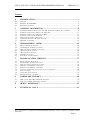


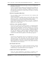


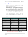
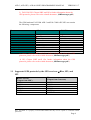
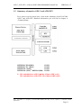


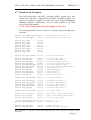

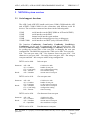
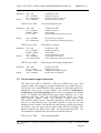


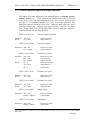


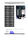
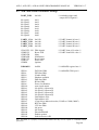


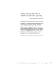


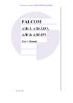


![E^YB?= ce``_bd VY\Uc V_b @QbQTYW] 4UReW BD](http://vs1.manualzilla.com/store/data/005839928_1-81490c34e940fa2480ecad1c81f1b8b0-150x150.png)