1
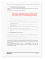
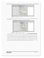
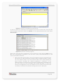
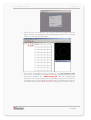
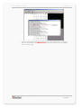
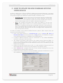
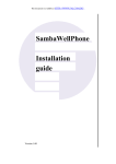
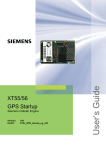
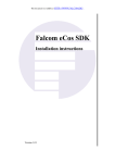
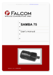
THIS DOCUMENT IS AVAILABLE AT HTTP://WWW.FALCOM.DE/
Falcom STEPPII
Getting Started
Version 1.02
STEPP II GETTING STARTED
VERSION 1.02
Index of contents
0
INTRODUCTION .......................................................................3
0.1
USED ABBREVIATIONS ...............................................................................................................3
0.2
RELATED DOCUMENTS ..............................................................................................................3
1
GETTING STARTED ...................................................................4
1.1
OVERVIEW OF STEPPII STARTER KIT ...........................................................................................4
1.1.1
1.2
Installing the STEPPII Starter Kit steps ...............................................................................6
TERMINAL EMULATOR SETUP ......................................................................................................6
1.2.1
Evaluating the STEPPII locally, using SiRFDemo software ......................................... 11
2
HOW TO UPDATE THE NEW FIRMWARE INTO THE STEPPII
DEVICE ..................................................................................14
Version history:
Version number
Author
Changes
1.00
Fadil Beqiri
Initial version
1.01
Fadil Beqiri
New manual layout
Note added.
1.02
Fadil Beqiri
The steps to update the new firmware into the STEPP II
changed.
This confidential document is the property of FALCOM GmbH and may not be copied or circulated without permission.
Page 1
STEPP II GETTING STARTED
VERSION 1.02
Cautions
Information furnished herein by FALCOM are accurate and reliable. However, no
responsibility is assumed for its use.
Please, read carefully the safety precautions.
If you have any technical questions regarding this document or the product
described in it, please contact your vendor.
General information about FALCOM and its range of products are available at the
following Internet address: http://www.falcom.de/
Trademarks
Some mentioned products are registered trademarks of their respective companies.
Copyright
The STEPPII user’s guide is copyrighted by FALCOM GmbH with all rights reserved. No
part of this user’s guide may be produced in any form without the prior written
permission of FALCOM GmbH.
FALCOM GmbH.
No patent liability is assumed with respect to the use of the information contained
herein.
This confidential document is the property of FALCOM GmbH and may not be copied or circulated without permission.
Page 2
STEPP II GETTING STARTED
VERSION 1.02
0 INTRODUCTION
This guide explains the basic steps for getting started with STEPPII terminal. The STEPPII
GSM/GPRS/GPS device allows a quick and uncomplicated configuration and
evaluation by the user via local RS232-interface (directly connected to the serial
port) or remotely via air interface.
With WindowsTM Hyperterminal application (utility that is pre-installed on all versions of
Windows 98, 98SE, Windows ME, Windows NT, Windows 2000 and Windows-XP) it is
possible to request GPS position data, and to execute a range of configurations.
The Falcom STEPPII can also be configured using the Configurator 2.0 software. The
software description can be found in a separated manual, file name
is
“Stepp_configurator.pdf” delivered on the CD.
0.1 Used abbreviations
Abbreviation
Description
GPS
Global Positioning System
NMEA
National Maritime Electronics Association
GSM
Global Standard for Mobile Communications
GPI
General Propose Input
CRLF
Carriage Return/Line Feed
bps
Bit per Second
0.2 Related documents
1. SiRF binary and NMEA protocol specification;
www.falcom.de/Service/Manuals/SiRF
2. SiRFDemo software and SiRFflash programming utility;
www.falcom.de/Service/Manuals/SiRF
3. stepp_II_hardware_manual.pdf
4. “Stepp Configurator” Configuration software
5. steppII_software_2.1.X.pdf
6. steppII_software_1.6.6.pdf
This confidential document is the property of FALCOM GmbH and may not be copied or circulated without permission.
Page 3
STEPP II GETTING STARTED
VERSION 1.02
1 GETTING STARTED
1.1 Overview of STEPPII Starter Kit
The SteppII device can be obtained as a single unit or as part of a starter kit. The
device has two antenna plugs, one for GSM and one for GPS. The device has a slot
where a GSM SIM should be inserted. The SIM card should be used for GSM
communication to the device. The device also has a Molex Micro-Fit 3.0 socket and
an AMP INFOPORT Series III header. The Molex socket gives access to the power
input and signals such as the inputs, outputs The AMP header gives access to signals
such as the microphone, the speaker and the RS232 serial connection.
The STEPPII Starter Kit provides an environment for evaluating and configuring the
STEPPII device. The kit can be used to emulate the final hardware setup used when
the device is installed. Connecting the device to the evaluation board gives easy
access to the device.
Image 2 gives an overview of the variety of components contained in Falcom’s
STEPPII Starter Kit:
•
•
•
•
Falcom STEPPII device with built-in bracket
•
•
•
•
•
•
•
16-pin configuration cable with MOLEX plug connection
GSM/GPS antenna
AC/DC adapter (European standard 220 AC/12V DC)
Evaluation box (This Eval-Board is not the same one to previous STEPP
evaluation board)
Cable with 15-pin AMP and DB15 plug connection
Audio cable
1,5m power cable
Modem cable set with DB9 plug connection
Handsfree loudspeaker and microphone
CD with
Configuration software Stepp Configurator
Hardware description
Software description
This confidential document is the property of FALCOM GmbH and may not be copied or circulated without permission.
Page 4
STEPP II GETTING STARTED
VERSION 1.02
Image 1: Scope of items in STEPPII Starter Kit.
The evaluation box has the following connection ports (see image 3):
•
•
•
Input for power supply (10 to 32V DC),
•
Configuration cable with 16-pin Molex connection to connect with 16-pin
Molex Connector of STEPPII Terminal,
•
8-pin RJ45 audio (MIC N1 and MIC P1, see hardware description
(“steppII_hardware_manual”) OUTPUT for alarm channel,
•
MIC/SPK INPUT/OUTPUT (SPK2 and MIC2, see hardware description
(“steppII_hardware_manual”) – connections for voice channel,
•
•
4 LEDs to signalise the status of the digital outputs 1 to 4 of the STEPPII,
•
•
Potentiometer to test analogue inputs 1 and 2,
DB9 serial interface for PC COM Port,
Audio cable with DB15 plug connection to connect with 15-pin AMP
connector of STEPPII Terminal,
9 switches to test the digital inputs 1 to 4, as well as IGN (ignition) and to
switch ON/OFF various device functions such as V+, ACCU OFF, MIC intern
and BOOT on the STEPPII Terminal (see “steppII_hardware_manual” for
detailed information),
MIC 1 INPUT alarm microphone.
Image 2: Connections of evaluation box
Descriptions on the output pins and the hardware of the connections on the STEPPII
are provided in “steppII_hardware_manual.pdf” chapter “Hardware Interfaces”.
This confidential document is the property of FALCOM GmbH and may not be copied or circulated without permission.
Page 5
STEPP II GETTING STARTED
VERSION 1.02
1.1.1 Installing the STEPPII Starter Kit steps
In general, be sure not to turn on the STEPPII terminal module while it is out of the
operating range of voltage and temperature stated described in the hardware
manual.
The kit can be set up using the procedure below.
WARNING:
PLEASE DO NOT USE THE PREVIOUS STEPP EVAL-BOARD (STARTER-KIT FOR
STEPP) FOR STEPPII TERMINAL. THE STEPPII EVAL-BOARD HAS A BUILT-IN LI-ION
BATTERY WHICH IS DIRECTLY LINKED TO THE “ACCU ON/OFF” SWITCHES
PLACED IN THE EVAL-BOARD AND TO THE VBAT+ PIN OF STEPPII. THIS PIN (ON
THE STEPPII) HAS IN NO CASE TO BE CONNECTED NEITHER TO THE OPERATING
VOLTAGE NOR TO THE GND, ELSE YOU WILL DAMAGE YOUR TERMINAL.
1. Connect both antenna plugs to the corresponding plugs on the STEPPII
device,
2. Connect the AMP connector on the cable to the AMP header on the STEPPII
device. Connect the DB15 plug on the other end of the cable to the
respective socket on the evaluation board,
3. Connect a Molex plug on the cable to the socket on the STEPPII device.
Connect the plug on the other end of the cable to the respective socket on
the evaluation board,
4. Connect the speaker and microphone to the respective sockets on the
evaluation board,
5. Use the serial cable to connect the evaluation board to a serial port on the
PC,
6. Insert the SIM card into the SIM interface of the STEPPII,
7. Connect the power module to the evaluation board and to the ac power
supply.
1.2 Terminal emulator setup
Please ensure that the STEPPII terminal is properly connected to the Eval-Board and
to the host device. Make sure that the STEPPII terminal is powered on and the GSM
LED indicator on the front side of device flashes.
If the STEPPII device is supposed to be configured using the Stepp Configurator,
please refer to a separate manual named “
The example below is based on the Windows™ Hyperterminal, because it is a
supplement tool which is also licensed by purchased Windows™. The STEPPII can also
be configured by using any other Terminal-Program. The instructions below describe
how to use the STEPPII (operating with Firmware V1.6.2 or V2.0XX) with a PC running
Windows 2000.
On the first time power-up you can use a terminal software which allows the
communication with a modem via RS232 serial port. On Windows 2000, starts the
HyperTerminal program.
This confidential document is the property of FALCOM GmbH and may not be copied or circulated without permission.
Page 6
STEPP II GETTING STARTED
VERSION 1.02
Figure 3: Using Microsoft Windows™ Hyper Terminal
Assign the name for a new session on the displayed window (e.g STEPP_II).
Figure 4: Assign the name for a new session
Choose the correct COM Port and baud rate settings (9600bps, 8 bit, no parity bit, 1
stop bit).
To control the STEPPII operating with firmware version “V2.1X”, use the
following pre-defined factory settings:
57600
8
No
1
None
bps
Data bits
Parity bit
Stop bit
Flow control.
To control the STEPPII operating with firmware “STEPPII Firmware V1.6.6”,
use the following pre-defined factory settings
9600
bps
8
Data bits
No
Parity bit
1
Stop bit
None
Flow control.
This confidential document is the property of FALCOM GmbH and may not be copied or circulated without permission.
Page 7
STEPP II GETTING STARTED
VERSION 1.02
Figure 5: COM Port transmission settings
If a connection to the STEPPII terminal is established, the transmitted protocols will be
displayed.
Please note that, if the embedded GPS reciver of the STEPPII device
(operating with 2.1.X firmware) is unable to calculate a valid position
due to the satellites on view (less then 3 satellites), please, change the
location of the GPS antenna and restart your STEPPII device. In order to
evaluate the GPS receiver, if valid positions are being received, see
section 1.2.1.
Figure 6: COM Port transmission settings
To sent a command to the STEPPII terminal while the GPS messages are being
displayed on the terminal program, the default configurations of terminal program
have to be changed. To do this, click the property button. Then select the Settings
tab sheet, and then click on ASCI setup... button to start the ASCI Setup dialog box.
This confidential document is the property of FALCOM GmbH and may not be copied or circulated without permission.
Page 8
STEPP II GETTING STARTED
VERSION 1.02
Figure 7: Connections properties.
On the appeared dialog box select the check box captioned ”send line ends with
line feeds”, click on OK button and close the opened dialog box.
Figure 8: Change the default setting
Now open a text file (txt extended file) and write “$PFAL,Config.Set.PIN=3333”
command which has to be sent to the STEPPII terminal (e.g see the figure below).
The value “3333” of PIN parameter has to correspond to the PIN number of your SIM
Card, which is provided by your mobile phone service provider. Please note that,
after the command is written, press the enter key to complete the command
(<CR><LF>), else the command will be ignored from the STEPPII terminal. Save the
opened file, for example “example .txt” and then close it. Please, remember file
directory. Note that, this command is available using the “2.1.X” firmware, only. Using
the “1.6.6” firmware another command has to be written into the text file.
This confidential document is the property of FALCOM GmbH and may not be copied or circulated without permission.
Page 9
STEPP II GETTING STARTED
VERSION 1.02
Figure 9: Write the command on the text file.
In order to sent the command to the terminal you have to tranfer the saved text file
with included command. Click the Transfer on the Hyperterminal menu and select
Send text file... .
Figure 10: Start the transfer program.
Select the saved text file “example.txt” from its directory and click the open button.
Now the command(s) included in the text file is (are) automatically sent to the
connected STEPPII terminal.
Note that, after the text file is sent to the device and it is accepted from
the device as well (command is written without single mistake), it writes
the user defined value onto the internal FLASH and it will be displayed
upon request. Sending the “$PFAL.Config.Show” command to the
STEPPII terminal, it responds only changed configuration (changed from
the user) while the GPS messages are being displayed. To find the
received configurations from the STEPPII use the vertical and horizontal
scroll bars of terminal. The default settings will not be displayed.
This confidential document is the property of FALCOM GmbH and may not be copied or circulated without permission.
Page 10
STEPP II GETTING STARTED
VERSION 1.02
Figure 11: Sending the command
More information how to test the Falcom STEPPII operating with firmware V2.0RC1
can
be
found
in
a
separated
manual.
Sections
on
the
“steppII_software_2.1.X_manual.pdf” user manual describe how to configure and
poll the current state of the STEPPII remotely via a TCP connection.
1.2.1 Evaluating the STEPPII locally, using SiRFDemo software
After you have connected the STEPPII to one of theavailable ports on your PC,
please, install the SiRFdemo software which is available on the CD or download it
from FALCOM’s Website:
www.falcom.de/service/downloads/SiRF/SiRFdemo.zip
1.
Run the SiRFdemo software by double clicking the SiRFdemo.exe file. The
SiRFdemo program will be automatically installed onto your computer.
2.
To start the SiRFdemo software, either double-click on the SiRFdemo.exe
installed file or if you have created a shortcut on your desktop, doubleclick the SiRFdemo.exe.
3.
The SiRFdemo software will appear as follow:
Before running the software, make sure that your PC is recognizing
STEPPII properly. In order to receive the valid positions for the current
location of the device, please, place the GPS antenna to the sky (no
obstacles).
On the activated Data Source Setup window, select the COM (e.g.
COM1) for SiRFdemo program. Using V2.1.X firmware set the baud
rate to 57600 bps. See figure below. Using STEPPII 1.6.6 firmware set
the baud rate to 9600 bps.
This confidential document is the property of FALCOM GmbH and may not be copied or circulated without permission.
Page 11
STEPP II GETTING STARTED
VERSION 1.02
Click the icon on toolbar by the up-down button (marked button in
figure below) the program will automatically detect the selected
COM port and starts evaluating.
The output messages can be viewed in the Development Data
screen. For a description of NMEA messages please download from
FALCOM’s Website the “SiRFmessages.pdf” file. The valid/invalid
protocols can be recognized in the $GPRMC protocol as shown in
the figure below. The capital letter A means, incoming protocols are
valid and the capital letter V means, incoming protocols are invalid.
This confidential document is the property of FALCOM GmbH and may not be copied or circulated without permission.
Page 12
STEPP II GETTING STARTED
VERSION 1.02
For more detailed information about the using of SiRFdemo software,
please download the SiRFdemo.pdf manual, which is also available
on our web page.
This confidential document is the property of FALCOM GmbH and may not be copied or circulated without permission.
Page 13
STEPP II GETTING STARTED
VERSION 1.02
2 HOW TO UPDATE THE NEW FIRMWARE INTO THE
STEPPII DEVICE
In order to allow users of Falcom STEPPII to utilize newly released firmware, a program
has to be available to update the on-board Flash-Memory. The new firmware and
an update program are distributed electronically via Internet or CD.
Important note: Please write down the important existing configuration
settings for the Falcom STEPPII using the current firmware. The update
procedure of a new firmware erases the whole internal flash memory
and the presettings stored on it will be absolutely erased, too.
Note: The update procedure from which the STEPPII is set into the
update mode (BOOT switch is set to HIGH) untill the update of the new
firmware is completed should take maximally 2 minutes. If this period of
time is exceeded and the STEPPII is still in the update mode, the update
procedure will be aborted and an error message will be appeared by
the used update software.
In order to update a new Falcom STEPPII firmware, please, follow step-by-step the
instructions described below:
•
drivers &
Point your web browser to www.falcom.de, go to support
firmware
STEPPII and download the “stepp_x.s“ file. The SiRFflash program
to update the firmware is available on the delivered CD.
•
If Falcom STEPPII terminal is still not connected to the STEPPII-STARTERKIT,
connect it, else go to the next step.
•
The update procedure takes place if the target system (Falcom STEPPII ) is
reset in the internal update mode. Therefore, if the terminal is powered on,
power it down (means, turn off the switches ACCU OFF, V+ and BOOT, on the
STEPPII EVAL-BOARD).
•
Make sure that all switches ACCU OFF, V+, IGN and BOOT others located on
the EVALBOARD are turned off (in the direction of marked name)
•
Start “SiRFflash.exe” program from the CD by double clicking the icon. The
Dialog Window shown below appears.
•
Make sure that the serial port of EVAL-BOARD is properly connected to one of
the available COM ports on your PC (e.g. COM1).
This confidential document is the property of FALCOM GmbH and may not be copied or circulated without permission.
Page 14
STEPP II GETTING STARTED
VERSION 1.02
•
Please, refer to the figure below for the following points. Select the Program
flash radio button in the Activity selection box
•
Select the Line where your Falcom STEPPII is connected (i.e COM1) and Baud
rate (115200) in the Communication settings box.
•
Select the Chip select (CSN0) and Chip offset (0) in the Flash location settings
box.
•
Choose the download file (the new firmware “*.S” is included in the
steppII_x.zip file) by using the Browse button into the File selection box.
•
Select Erase whole chip, in the Programming options box.
•
Now, turn on the switch BOOT (set the system into update mode), and then
turn on the switches ACCU OFF and V+. The system is now in the update
mode (from now just 2 minutes are available before the system (STEPPII)
perform internally a reset).
•
Press Execute button to start the flash update programming.
•
The current positions of the programming progress will be displayed in the
Progress bar and the Total, Erase and Burn process will be shown in the Timing
box.
Note: Do not interrupt this procedure. A partially reprogrammed flash
memory could lead to invalid operation of the terminal and permanent
damage of the components.
•
If an error is generated by clicking the Execute button or during flash
programming, check cables and retry the operation or click the help button
to get the troubleshooting described in the help file of SirfFlash program.
If download has been completed successfully, power down the Falcom
STEPPII (turn off the switches ACCU OFF, V+ and BOOT). Your Falcom STEPPII
is ready to run with the new firmware. The Falcom STEPPII with the new
firmware is automatically started at the next power up (turn on the switches
ACCU OFF, V+). A complete configuration has to be done.
For further evaluation of the updated firmware in the FLSH memory of target
device, please refer to the corresponding documentation, which is
included on the delivered CD.
This confidential document is the property of FALCOM GmbH and may not be copied or circulated without permission.
Page 15