1
ZEROAIR
Version 1.0
User's Manual
August 1983
[
'
Assistance and Information:
K. Ford
Design Aids Engineer
Solar Programs Office
Sir Charles Tupper Building
Riverside Drive
Ottawa K1A OM2
(613) 998-3641
This document is not a departmental publication.
Do not cite as a reference or catalogue in a library.
1
i
1
1.
INTRODUCTION
The ZEROAIR computer program was developed by Enermodal Engineering
Limited to simulate the performance of solar space heating systems using airbased solar collectors and no storage unit. The program can accept data of
all PUSH approved air-based collectors (Amherst 200, Solartech Solair, and
Watershed A-100) and any other parallel plate air-based collector.
1
ZEROAIR is the only computer program capable of simulating zero
storage air-based solar space heating systems. Performance calculation s
use a one-hour time step to ensure maximum accuracy.
'\
In general, this type of system is best suited to buildings that
can be allowed to fluctuate in temperature (e.g. warehouses). Buildings that
require precise temperature control and have high internal heat gains during
the day are not suited to this type of.solar heating system. Because there is no
storage of heat (other than in the building structure and its contents),
the solar heating system can supply very little of the nighttime heating load.
As such the system should be sized to meet under 40% of the heating load.
A larger system would be inefficient and therefore expensive.
The ZEROAIR computer program will provide an accurate estimate of the
thermal performance of zero storage solar space heating systems provided
that the user supplies system parameters within the program limitations . All
users should read and understand this manual before using the program.
2
2. THE ZEROAIR COMPUTER PROGRAM
2.1 System Operation
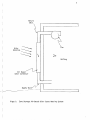
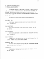
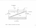
A zero storage air-based solar space heating system is shown in
Figure 1. The system consists of air-based solar collectors, supply and
return ductwork, fan and control system. In many cases the collectors can
be mounted directly on the south wall of a building with no need for collector
support racks or supply and return ductwork. If collector air is blown
directly into the building it may be necessary to install a ceiling fan to
mix the building air.
The control system for this type of system is quite simple. There
are only two modes of operation: system on and system off. If the temperature
of the collector is greater than that of the building, air is circulated
through the collectors. The fan would continue to operate until the collector
temperature drops below the building temperature or the maximum allowable
building temperature is exceeded. On spring and fall days when the solar
gain exceeds the heating load, the system will constantly cycle on and off
so as not to exceed the maximum building temperature.
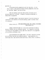
2.2 Using the ZEROAIR Program
Using the ZEROAIR computer program is relatively easy. The program
has been written so that the user enters the system description interactively
with the computer. The program makes some fundamental checks on the suitability
of the input parameters. If a parameter appears unrealistic, a warning is
printed although the program accepts the value.
Before the program can be run hourly weather data (solar radiation
on a horizontal surface and ambient temperature) must be available. This
data can be obtained from Atmospheric Environment Service. The first step in
the program execution is to calculate solar radiation on the collector surface
and store it in a scratch file. During the simulation the program accesses
the scratch file. If collector slope and orientation remain the same on
successive runs, the same scratch file is used. If the values are changed,
the scratch file is automatically recalculated.
3
Return
Duct
\~
Solar
-----Radiation ~
an
~
Building
Air Based
Solar Collector
Supply
Figure 1:
Duct~
Zero Storage Air-Based Solar Space Heating System
4
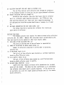
When the user accesses the program, a series of questions concerning
the program will have to be answered. These questions are shown in Section 2.3.
When the questions have been answered, the user has the choice of several
commands
C or CHANGE
D or DEFAULT
L or LIST
Mor MODIFY
R or RUN
S or STOP
T or TITLE
CHANGE
DEFAULT
LIST
MODIFY
RUN
The use of these commands is discussed below.
this command is used to change the program input data. A list of
the input data and their meanings is given in Section 3.1. The
command is of the form
C or CHANGE Parameter # = New Value
e.g. C C3 = 50
Several changes can be made on one line with or without the equal sign
e.g. C C4 = 0.0, Tl 3
this command is used to re-initialize all the input parameters to
their default values. There are no options with this parameter.
this command is used to list either all the input parameters, all
the parameters of one section or an individual parameter.
Lor LIST ALL - lists all parameters
L C- lists all collector parameters
L C3- lists collector slope
this command is used to modify the default collector characteristics
i.e. to change the collector type.
this command is used to run the program. If the option ''P'' is
used a copy of the output will be sent to the printer. If a
simulation period other than one year is required, the first day
of the simulation followed by the length of the simulation should
be entered
e.g. RUN or R P 31,28 - this would execute the program starting
January 31st and run for 28 days. A copy of the output would be
sent to the printer.
5
STOP
TITLE
this command stops the program.
this command is used to insert a title into the program output.
The same title will be printed on every successive run unless it
is changed
e.g. TITLE or T THIS IS RUN NUMBER 1.
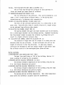
2.3 Tutorial Session
8
3.
SYSTEM INPUT PARAMETERS
The following sections describe the parameters used in the ZEROAIR
computer program. The default value for each parameter is included with the
definitio n.
3.1 Definition of Input Parameters
There are three separate sections of input data:
C - collector data
T - collector test data
L - building heating load data
The parameters for each of these sections are discussed below.
Collector Data
Cl NUMBER OF COLLECTORS (2)
The number of collector s in the solar heating system.
C2 NUMBER OF COLLECTORS IN SERIES (1)
The number of collector s that are connected in series as opposed
to parallel.
C3 COLLECTOR SLOPE (DEGREES) (45)
The angle that the collector is tilted from the horizontal in
degrees. This parameter must be between 0 and 90. If this parameter
is different from the value on the scratch weather file, the weather
data will automatically be reprocessed.
C4 COLLECTOR ORIENTATION (SOUTH=O EAST=+, DEG) (0)
The number of degrees that the collector is oriented off due south
(east is positive, west is negative). This parameter must be between
-90 and 90. If this parameter is different from the value on the scratch
weather file, then the weather data will automatically be reprocessed.
9
C5 COLLECTOR FLOW RATE PER UNIT AREA (L/(SEC*M2) (10)
The air flow rate per unit collecto r area through the collecto rs
for the proposed system in litres per sec per square metre of collecto r.
C6 PERCENT COLLECTOR LOOP AIR LEAKAGE (5)
Percent of the collecto r flow rate that leaks into the collecto r
loop (i.e. collecto r under negative pressur e). For a collecto r loop
under positive pressure (air leaks out) use a negative percentage. A
well designed and installe d system should have a leakage rate of under
10%.
C7 FAN POWER CONSUMPTION PER UNIT AREA (W/M2) (10)
The energy required to operate the collecto r fan in watts per
square metre of collecto r.
Collector Test Data
The program contains test results for three air-based solar collecto rs
(effecti ve Jan. 24, 1983): Amherst 200, Solartech Solair and Watershed A-100.
These test results can be updated or other test results added.
T1 GROSS AREA OF ONE COLLECTOR (M2) (2)
The gross or outside area of one collecto r in square metres.
T2 NUMBER OF COLLECTORS IN SERIES WHEN TESTED (1)
Number of collecto rs connected in series when it was tested,
typicall y one.
T3 FR-TAU-ALPHA (TEST) (0.5)
The FR(Ta)e of the collecto r when tested by a certifie d laboratory
(based on gross collecto r area).
T4 FR-UL (W/M C) (TEST) (4.0)
The FRUL of the collecto r when tested by a certifie d laboratory
(based on gross collecto r area) in W/(m°C).
T5 INCIDENT ANGLE MODIFIER (-0.1)
Coefficient that reduces collecto r solar transmission for incident
angles off the normal. The value for this coeffic ient, b0 , is obtainable
from collecto r data sheets and is usually negative. If test results are
not availab le use -0.10 for single glazed collecto rs and -0.17 for double
glazed collecto rs.
10
T6 COLL. TEST FLOW RATE PER UNIT AREA (L/SEC*M2) (10.)
The air flow rate through the collector at test conditions in
litres per second per square metre of collector.
T7 TRANSMISSION-ABSORPTION PRODUCT (0.9)
The (,a) effective of the collector. This can be estimated as 1.01
times Ta for a single glazed _collector where ' is the glazing solar
transmission and a is absorber solar absorptivity.
TS RATIO OF COLLECTOR APERTURE TO GROSS AREA (0.9)
The ratio of the collector aperture area (i.e. window area) to the
gross area. Typically this value is usually close to 0,9, actual values
can be obtained from collector data sheets.
T9 COLLECTOR FLOW CHANNEL HEIGHT (MM) (6)
The spacing between the upper and lower absorber plate in millimetres.
For a curved upper absorber use the average spacing. In general decreasing
the flow channel height increases the collector FR although this will
result in a higher collector pressure drop.
T10 COLLECTOR FLOW CHANNEL LENGTH PER COLLECTOR (M) (1)
The distance or length that the air stream is in contact with the
absorber plate for one collector. In most collectors this will be the
length of collector in the flow direction. In some cases, however,
collectors are designed so that the contact length is much shorter than
the collector such as in the overlapped glass plate collector.
Heating Load Data
L1 BUILDING HEAT LOSS COEFFICIENT (W/C) (300.)
The heat loss coefficient or "UA" of the building. Section 3.3
gives a method of estimating this parameter.
L2 MINIMUM DAYTIME BUILDING TEMPERATURE (C) (20.)
The minimum allowable temperature of the building during the day
(i.e. the furnace thermostat set point).
L3 MINIMUM NIGHTTIME BUILDING TEMPERATURE (C) (16.)
The minimum allowable temperature of the building during the night
(i.e. the furnace thermostat set point at night).
L4 MAXIMUM ALLOWABLE BUILDING TEMPERATURE (C) (25)
The maximum desired building temperature. That is the temperature
above which the building's occupants would be uncomfortable.
11
L5 BUILDING THERMAL CAPACITANCE (MJ/C)
The thermal or heat capacitance of the building. Most buildings
have a thermal capacitance of 0.1 MJ/C for every square metre of floor
area, although full warehouses would be slightly higher.
L6 DAILY INTERNAL HEAT GAIN (KJ/DAY) (3000)
The average daily internal heat gains from lights, people and
solar gains through windows in KJ.
L7 HOURLY INTERNAL HEAT GAIN PROFILE (PERCENT)
24 hourly values of the percent of the daily internal heat gain
occurring within that hour. The first value is for the hour 12 midnight
to 1 a.m.
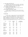
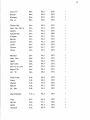
3.2 Weather Data
At present there is weather data for 46 cities that can be used by
the program. These cities are tabulated below. The solar radiation data as
supplied by Atmospheric Environment Service is of two types: derived or
measured. Measured data is as recorded by their monitoring equipment (with
missing data estimated from the previous day's values). Derived data is
predicted by using other meteorological data such as rainfall, cloud cover etc.
Province
Latitude
( Deg.)
Year
Solar Rad.
Derived/Measured
Victoria
Prince George
Vancouver
Summerland
B.C.
B.C.
B.C.
B.C.
48.7
53.9
49.2
49.6
1971
1974
1971
1971
D
M
M
D
Frobisher Bay
Resolute
N.W.T.
N.W.T.
63.8
74.7
1975
1971
D
M
Edmonton
Medicine Hat
Alta.
Alta.
53.6
50.0
1971
1971
M
D
Urani urn City
Swift Current
Saskatoon
Sask.
Sask.
Sask.
59,6
50.3
52.2
1971
1971
1971
D
D
D
City
12
Churchill
Brandon
Winnipeg
The Pas
Man.
Man.
Man.
Man.
58.8
49.9
49.9
53.8
1975
1971
1971
1971
D
D
M
M
Thunder Bay
Sault Ste. Marie
Sudbury
Kapuskas i ng
Kingston
Muskoka
Windsor
London
Toronto
Ottawa
Ont.
Ont.
Ont.
Ont.
Ont.
Ont.
Ont.
Ont.
Ont.
Ont.
48.4
46.5
46.5
49.4
44.2
45.0
42.3
43.0
43.7
45.4
1971
1971
1971
1966
1971
1971
1971
1971
1971
1971
D
D
D
M
D
D
D
D
M
M
Montreal
Sept. I1 es
Quebec
Sherbrooke
Riviere du Loop
Bagotville
Val D'Or
Que.
Que.
Que.
Que.
Que.
Que.
Que.
45.5
50.2
46.8
45.4
47.8
48.3
48.0
1971
1974
1971
1971
1971
1971
1971
M
M
D
D
D
D
D
Fredericton
Charlo
Chatham
Moncton
St. John
N.B.
N.B.
N.B.
N.B.
N.B.
45.9
48.0
47.0
46.1
45.3
1971
1971
1971
1971
1971
M
D
D
D
D
Charlottetown
P.E.I.
46.3
1971
D
Truro
Halifax
Sydney
Yarmouth
N.S.
N.S.
N.S.
N.S.
45.4
44.7
46.2
43.8
1971
1971
1971
1971
D
M
D
D
13
Nfld.
Nfld.
Nfld.
Nfld.
St. John's
Gander
Stephenville
Goose
47.6
49.0
48.5
53.3
1971
1971
1971
1971
M
D
D
M
3.3 Estimation of Building Heat Loss Coefficient
For new homes the building heat loss coefficient can be estimated by
adding up the heat loss from each building wall, window and door and including
an estimate of air infiltration . The ASHRAE Handbook of Fundamentals and many
heating textbooks show how this can be done. This calculation is normally
done for every house in order to size the furnace.
1f heating bills are available it is easy to estimate the building
heat loss coefficient (UAb) using the formula
UA
b
=
11600 FC nf
DD HV
(in W/"C)
where FC is the fuel consumption in litres of oil, cubic metres of
gas or kWhr of electricity ,
nf is the seasonal furnace efficient, typically 0.6 for oil
and natural gas and 1.0 for electricity ,
HV is the heating value of fuel
oil = 25 1/GJ
natural gas= 27 m3 /GJ
electricity = 278 kWhr/GJ
DD is the yearly total of degree-days below 18"C in "C-days
Vancouver - 3000
- 4000
Toronto
- 4600
Ottawa
Fredericton - 4600
- 5900
Winnipeg
Yellowknife - 8600
Typical values for the building heat loss coefficient are
100 W/"C super insulated home
250 W/"C average home
500 W/"C poorly insulated home.
14
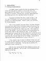
4. DESCRIPTION OF PROGRAM OUTPUT
4.1 Thermal Analysis Results
The thermal analysis of the system is printed in monthly intervals
with a yearly summary printed at the end. The results are an estimate of
the system performance of a properly designed and installed system. The
program cannot account for improperly insulated ductwork, fan motor failure
or other system faults.
The definition of the seven monthly output values follow.
SOLAR AVAIL. (GJ)
Total solar radiation incident on the collector over the time
period in gigajoules.
SOLAR COLLECT (GJ)
Solar energy converted to heat by the solar collector over the
time period.
SOLAR DELIVER (GJ)
Solar energy delivered to the building that reduces the auxiliary
energy consumption.
SPACE HT LOAD (GJ)
The auxiliary heat required over the time period to space heat the
building if there was no solar heating system.
AUX. HEATING (GJ)
Auxiliary energy required to space heat the building over the time
period when the solar heating system is used.
FAN POWER (GJ)
The electrical energy required to operate the collector fan over
the time period.
15
MAX. TEMP (C)
The maximum building temperature over the time period. If this
value is equal to the maximum allowable building temperature, then heat
must have been "dumped" from the building.
After the monthly totals have been printed, the yearly sum of
the seven quantities is printed. A summary of energy use and savings is
then printed in gigajoules.
The ENERGY SAVING is the percent reduction in auxiliary energy use
attributable to the addition of the solar heating system i.e. percent solar.
It is defined as
Energy Saving (%)
= 100
(Space Heating Load - Aux. Heating + Fan Power)
Space Heating Load
AVERAGE SYSTEM EFFICIENCY (%) is the solar contribution divided by
the solar radiation over the simulation period. It is important to note that
if the daily air flow schedule is very short this value will be low regardless
of the collector performance curve.
SOLAR CONTRIBUTION PER SQUARE METRE is the solar contribution divided
by the collector area over the simulation period. A good application of a
zero storage solar space heating system would have a value of over 1.0 GJ/m 2 /yr.
16
5. PROGRAM ALGORITHM
5.1 Overview of Program Operation
The ZEROAIR computer program calculates the performance of zero
storage solar space heating systems on an hour-by-hour basis. The
basic assumption of the program is that for the purpose of calculating
performance all variables, including solar radiation, ambient temperature
and building heat loss can be considered constant for each hour.
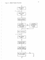
The program calculation flow chart is shown in Figure 2. The
first step in the program is the input and modification of the program
parameters in an interactive manner. Section 3 gives a full description
of the input parameters.
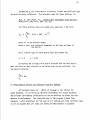
After all the parameters have been entered, the program calculates
the collector heat removal factor for the test values of flow rate and flow
path length using the method given in Section 5.2. This value is compared
to the value of FR found from the collector FRTa term. The two values are
printed at the terminal. At the test condition, the calculated value of FR
will be either higher or lower than the test value. If the difference
between the values is greater than 20% the program prints a warning and returns
to the input mode. The collector heat removal factor is then adjusted for the
system flow rate, flow path length and duct air leakage. The algorithm for
adjusting the collector characteris tics is given in Section 5.3.
If the collector slope or azimuth is different from the value used
to calculate the solar radiation in the scratch file then the solar radiation
on a tilted surface is recalculate d. The algorithm for performing this
calculation is given in Section 5.4.
When the solar radiation and the input parameters are correct, the
program begins the simulation. The first step is to calculate the building
heat loss for that hour
17
Figure 2:
ZEROAIR Program Flow Chart
t
Read Default
Data
2
Modify Input
Data
Correct Collector
Characteristics
Is solar
radiation on a
til ted surface
available?
Calculate
solar radiation
on tilted
surface
N
y
Start Simulation
1
Read Weather
Data
Calculate Space
Heating Load
Calculate New
Building Temp(Tbg'
Can solar energy
be collected?
,.1}
N
..-l,..
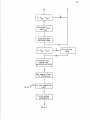
18
Is Tbg
N
Tmax ?
<
y
Calculate Q ol
and Qfanc
Calculate New
Building Temp.
Is Tbg
<
Tmin 7
y
Calculate aux.
energy for
existing building
Add energy flows
to old values
N
Go to 1
Is the simulation
over?
y
Print system
performance
Go to 2
Calculate Aux.
Energy
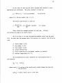
19
If there was no other energy input to the building, the building temperature
would become
Provided that this new value is below the maximum allowable temperature and
heat can be collected, the solar heat delivered to the building can be
calculated
where K is the incidence angle modifier factor
= 1 + b0 (1/cose - 1.)
The new building temperature is then
If this building temperature is greater than the maximum allowable temperature,
then all the solar heat for that hour is not usable. The amount of solar heat
that is usable is given by
I (T" - TI )
)
I
QI = Q (Tmax - Tbg
bg
bg
s
s
If the building temperature is below the minimum allowable temperature then
auxiliary energy is used to raise the temperature.
The building heating load (i.e. how much auxiliary energy is required
to heat the building without the solar heating system) is calculated in the
same manner as above, but without any solar gains. It should be noted that the·
yearly building heating load is not the sum of the hourly building heat losses
from the solar heated building. The solar building will be at a higher
temperature and thus have higher heat losses than the building with no solar
system. Since we are interested in the energy savings as a result of installing
20
a solar heating system, our base energy consumption should be that of the
existing or non-solar building.
The hourly values of the above energy flows are summed and monthly
and yearly totals printed. A full description of the output is given in
Section 4.
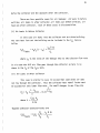
5.2 Algorithm for the Calculation of FR
Two separate algorithms are used for the calculation of FR, one for
parallel plate solar collectors and one for fibre matrix solar collectors.
It is important to note that a correction on FR for the number of collectors
in series is not necessary provided that the mass flow per unit area is kept
constant.
i)
FR for Parallel Plate Solar Collectors
FR is given by:
F
R
where F'
= m Cp (1 - exp(-F'UL/(m Cp)
U
L
=
U0 /(U 0 + UL)
All of the variables are constant except form (mass flow rate per
unit area) and U0 (the total plate to fluid heat transfer coefficient). m
is given each hour by the air flow rate schedule, thus, a new value of U0
must be calculated for each hour. U0 depends on the collector design.
The equations for U0 given below were taken from:
Hollands, K.G.T. and Shewen, E.C., Journal of Solar Energy Engineering,
Vol. 103, No. 4, November, 1981. "Optimization of Flow Passage
Geometry for Air-Heating, Plate-Type Solar Collectors".
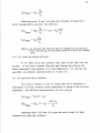
21
where h is the radiative heat transfer coefficient between the
r upper and lower absorber plates
if we assume that the inside of the air channel is painted black:
where T1 and T2 are the temperatures of the upper and lower absorber
plates
hpf is the convective heat transfer coefficient between the
plate and the air stream
hpf
for Re
<
= Nu • k/(2.b)
where K is the conductivity of air
b is the spacing between the upper and lower absorber plates
Nu is the Nusselt number.
2000 (Reynolds number)
Nu
= 5.385
+ 0.148 • Re • b • n/L
where n is the number of air flow passage channels (typically equal
to 1)
L is the collector flow path length
for 2000 < Re < 10000
Nu
for 10000
<
Re
= 0.00044
100000
Nu = 0.03
Re
1·2
+ 9.37
Re
0·471
b • n/L
~
where Re
2
Re
0·74
+ 0.788 • Re
0·74
• b • n/L
mL
= .::....::::....::.
]1
if Re is greater than 100000 the program sets Re equal to 100000.
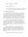
ii)
FR for Fibre Matrix Collectors (see Figure 3)
The estimation of FR for fibre matrix collectors requires a different
formulation for FR. FR can be though of as the ratio of the actual useful
Solar Radiation
(I)
~
I
.
hpf
•
T
a
Glazings
UL
T"
~
Air Flow In
~~II
--<!"~
F"b
.
1 re Matnx
Air Flow Out
~
Tfi
•
Tfo
Back Insulation
Figure 3:
Schematic of Fibre Matrix Solar Collector
N
N
23
energy to the useful energy if the absorber plate were at the fluid inlet
temperature (Tfi). For a ventilation collector FR is:
F
r
=
Ta. I
- UL (Tave - Tfi)
UL(Tfi - Tfi)
Ta.I-
Ta. I
where Tav is the average temperature that the collector loses heat
e at. This temperature is normally the average plate
temperature, however, a fibre matrix collector has inlet
air blowing across the lower glazing thus loses heat from
a lower temperature. For a fibre matrix collector Tave is:
Tave
= (hr Tplate + hpf Tfi)/(hr + hpf)
where hpf is the convective heat transfer coefficient between the
lower glazing and the air stream
hr is the radiative heat transfer coefficient between the fibre
matrix and the lower glazing. Because of the nature of the
fibre matrix, hr is a weighted average of the value of hr
for each layer of fibres with the top layer having a weighting
of 1 and the bottom layer having a weighting of 0. By
integrating the values for hr over the depth of the matrix,
hr can be approximated by:
)
T )/1.222
cr(T2+T2
2 (T 1 + 2
1
2
2
hr2 = cr(Tf 0 + T2 ) (Tfo + T2)/1.222
Tl is the temperature of the top of the fibre matrix
T2 is the temperature of the lower glazing
where hrl
=
The average fibre matrix plate temperature can be calculated by:
where U0 is the fibre matrix to air heat transfer coefficient
Tfm is the average fluid temperature.
24
Estimating U0 for fibre matrix collectors is much more difficult than
for parallel plate collectors. The reference used for these equations is:
Kays, W. and London, A.L., Compact Heat Exchangers Second Edition,
McGraw-Hill, New York, 1964, pg. 129.
For fibre matrices Kays and London give equations of the form:
U0
=X
· mCp
213
I (Rey • Pr )
where Pr is the Prandtl number
where x and y are constants dependent on the type and shape of
the matrix.
For a similar type of fibre matrix Kays and London give:
X
= 1.3
y
= 0.45
By knowing the average fibre matrix diameter and the fibre matrix
mass, the ratio of heat transfer to collector area can be calculated. For
the Amherst collector
5.3 Algorithm to Correct for Collector Loop Air Leakage
All ductwork leaks air. While air leakage is not critical for
indoor ductwork, it can seriously decrease performance for outdoor ductwork.
The collector performance characteristics can be modified to account for this
decrease in performance. The algorithm used in the program is taken from
reference 1 with extensions for the case of air leaking out of the collector loop.
It will be assumed that air leaks are evenly divided between the ductwork
25
before the collector and the ductwork after the collector.
There are four possible cases for air leakage: air leaks in before
collector, air leaks in after collector, air leaks out before collector, air
leaks out after collector. Each of these cases is discussed below.
(i) Air Leaks In Before Collector
In this case air leaks into the collector and out of the building.
The extra heat lost out the building can be included in the FRUL term as
follows
where LR is the ratio of the leakage rate to the collector flow rate
In this case the full air flow goes through the collector so there is no
change in the FR or the FRTa term.
(ii)
Air Leaks In After Collector
This case is similar to case (i) except that some of the air does
not flow thorugh the collector. Thus the collector heat removal factor must
be adjusted for this lower flow rate. For small changes in mass flow rate
1
1 - L
F' = F
R
R
(
where X =
R)[l - (1-X) 1-LR]
X
FRUL A
c
.n cp
Thus the collector characteris tics are
F U
R Lleaks
= F U
{R)
R L FR
+ LR m Cp
Ac
26
Combining cases (i) and (ii) gives the collector characteris tics
for air leakage before and after the collector
(1 - LR) + 2L
mCp
R A
c
where L is one half the ratio of the air leakage rate to collector
R flow rate and F' is calculated based on one half the leakage
R
rate
(iii)
Air Leaks Out Before Collector
If air leaks out of the collector loop, then air must leak into the
building. In this case a reduced flow rate goes through the collector and
the air exhausted to the outdoors is at room temperature. This case has the
same effect on collector characteris tics as in case (ii).
(iv)
Air Leaks Out After Collector
This case is similar to case (i) except that the air exhausted to
the outdoors is at the collector outlet temperature as opposed to the building
temperature. The collector characteris tics for this case are
Combining cases (iii) and (iv) gives the case of equal air leaks
out before and after the collector.
27
F'
FU
R Ll eaks
=
FR-raleaks
=
FRUL (__!) (1 - LR) +
Fr
2LR
mCp
Ac
F'R
FR-ra(-) (1 - LR)
FR
where LR is one half the ratio of the air leakage rate to collector flow
rate and FR is calculated based on one half the leakage rate
5.4 Algorithm to Process Weather Data
Most Canadian weather stations measure only total solar radiation on
a horizontal surface. Most solar collectors, however, are tilted toward the
sun to increase the incident solar radiation. The program determines hourly
values of total solar radiation (beam, diffuse and reflected) on a tilted
surface and stores the values in a scratch file. The algorithm for converting
horizontal solar radiation to tilted solar radiation is similar to the method
used in "Solar Engineering of Thermal Processes" by Duffie and Beckman (2).
In order to estimate the solar radiation on a tilted surface it is
necessary to split the total measured horizontal solar radiation into its
two components: beam and diffuse. It is possible to estimate the amount of
diffuse solar radiation from the ratio of the measured solar radiation to the
extraterrestrial solar radiation. If this ratio is low then the solar radiation
must be mostly diffuse; if this ratio is high the solar radiation must be
mostly beam.
When the beam and diffuse solar radiation components are known,
standard geometric relations can be used to estimate the solar radiation
components on a tilted surface. When estimating solar radiation on a tilted
surface a third component is introduced: reflected radiation. Reflected
radiation can be estimated from the beam radiation and the ground albedo or
reflectivity.
The program equations and execution procedure are given below.
28
At the start of each day the solar constant and the earth's solar
declination are calculated. The solar constant is given by:
Sc
= 4871.0 (1.
+
in KJ/(hr·m2 )
0.33 cos(2nN/365)
where N is the day number (Jan 1 is 1).
The earth's declination is given by:
0
= 23.45 * 2n sin (~{284
~0
+ N)/365)
360
(in radians)
These values are assumed constant for each day.
calculations are made on an hourly basis.
file.
order.
All other
The first step is to read the measured weather values from the data
For each hour the weather data file contains six values in the following
1)
2)
3)
4)
5)
6)
month number (1-12)
day number (1-31)
hour number (1-24)
ground reflectivity
solar radiation on a horizontal surface (in Watts/m 2 )
ambient temperature (in °C)
The extraterrestrial solar radiation on a horizontal surface is
calculated by:
where cos(ez) is cosine of the zenith angle (angle between the beam and
the vertical)
cos(ez)
= cos{~) cos(o) cos w +
sin~
sino
29
is the latitude of the location
w is the hour angle.
~
The diffuse solar radiation (Hd) can be estimated using a correlation
by Orgill and Hollands (3).
if 0.75 < KT
= 0.1769 H
if 0.35
Hd = (1.55699 - 1.84013 • KT) H
if 0.0 ~ KT
Hd = (1. - 0.248857 • KT) H
Hd
~
~
KT
~
0.35
0.75
where H is the measured hourly solar radiation
KT is the ratio of measured solar radiation to the extraterres trial
solar radiation
= H I Hex
The beam radiation (Hb) is simply the total measured solar radiation
minus the diffuse radiation.
The next step is to calculate the ratio of beam radiation on the
tilted surface to that on the horizontal surface (Rb).
where cos(eT) is the cosine of the angle of incidence of beam radiation,
between the beam and the normal to the surface.
cos(eT) = sin(o) sin(~) cos(s) - cos(o) cos(~) cos(s) cos(w) +
cos(o) sin(~) sin(s) cos(y) cos(w) cos(o) sin(s)
sin(y) sin(w)
y is the azimuth angle measured from south (east is positive, west
is negative)
30
Thus, the beam solar radiation on the tilted surface is
The diffuse solar radiation component on the tilted surface is
estimated using the radiation view factor from the collector to the sky
with correction factors for non-uniform distribution of diffuse radiation.
The correction factors for anisotropic diffuse radiation are
taken from Temps and Coulson (4) and Klucher (5). The resulting equation is:
where F
= 1 - (Hd/H) 2
The reflected solar radiation on the tilted surface (Hr) is
H
r
where
p
= (1- cos(s)) PH
2
is the ground reflectivity
The total solar radiation on the tilted surface (HT) is the sum of
the beam diffuse and reflected solar radiation components.
Hourly values of total solar radiation on a tilted surface, ambient
temperature, day number and hour number are written to the scratch file.
When all the data has been processed and written to the scratch file, the
file is rewound to be ready for the system simulation.
31
6.
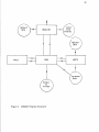
PROGRAM STRUCTURE
The program structure is described in this section. Only those
individuals interested in modifying the program need read this section.
of
1)
2)
3)
4)
The program flow chart is shown in Figure 4. The program consists
a mainline and three subroutines:
MAINLINE - contains the interactive front-end for reading and modification
of system data,
WEATH - subroutine for converting measured horizontal solar radiation
to the tilted surface,
ZERO - subroutine to calculate system performance on an hourly basis,
FRCALC - subroutine to calculate the collector heat removal factor FR
for a given flow rate.
Six file definitions must be made before the program can be run:
Terminal (Read) - (Unit 5) is the device used for data input. The program
will send all questions and prompts to this device.
Printer- (Unit 7) is the device that receives the printed output (i.e. a
printer). If a send and receive printer is being used unit 7
need not be defined.
Weather Data - (Unit 1) is the file containing the TRNSYS compatible weather
data. The data must be written in the format (2X, I2, 2X, 12,
2X, 12, F3.1, !3, F6.1) and contain month number, day number,
hour number, ground reflectivity, ambient temperature (°C),
and solar radiation on a horizontal surface (W/m 2 ).
Processed Data - (Unit 19) is the file that is created by the program
containing the solar radiation on the tilted surface and
ambient temperature.
Terminal (Write) - (Unit 6) is the device that receives questions from the
program concerning the input of data.
Default Data - (Unit 4) is the file containing program default data.
The ZEROAIR program is written in FORTRAN 77. In order to compile
this program on your system, it must be able to handle this improved version
of FORTRAN.
32
HAINLINE
FRCALC
ZERO
Input
from
Terminal
WEATH
Processed
Data
Output
to
Printer
Figure 4:
ZEROAIR Program Structure
33
7.
REFERENCES
1.
Mitchell, J.C. et al., FCHART 4.0 User's Manual, University of
Wisconsin-Madison, EES Report 50, September 25, 1980.
2.
Duffie and Beckman, Solar Engineering of Thermal Processes, John Wiley
and Sons, New York,
3.
Orgill, J.F. and Hollands, K.G.T., Solar Energy, Vol. 19, No. 2,
"Correlation Equation for Hourly Diffuse Rad1ation on a Horizontal
Surface".
4.
Temps, R.C. and Coulson, K.L., Solar Energy, Vol. 19, No. 2, "Solar
Radiation Incident upon Slopes of Different Orientation".
5.
Klucher, T.M., Solar Energy, Vol. 23, No. 2, "Evaluation of Models to
Predict Insulat1on on Tllted Surfaces".
34
8.
A
Ac
Afm
b
cbg
Cp
F'
FR
FRTa
FRUL
H
Hb
HbT
Hd
HdT
Hex
hpf
hr
Hr
HT
I
KT
L
LR
m
n
N
Nu
Qbg
Qig
Q5
Rb
NOMENCLATURE
total collector area
area of one collector
surface area of fibre matrix
collector channel height
thermal capacitance of the building
specific heat
U0 /(U 0 + UL)
collector heat removal factor
collector transmission-absorption coefficient
collector heat loss coefficient
measured hourly solar radiation
beam hourly solar radiation
beam hourly solar radiation on a tilted surface
diffuse hourly solar radiation
duffuse hourly solar radiation of a tilted surface
extraterrestrial hourly solar radiation
plate to fluid convective heat transfer coefficient
radiative heat transfer coefficient
reflected hourly solar radiation
solar radiation on the tilted surface
total incident solar radiation
clearness index
length of collector in flow direction
ratio of collector loop air leakage to collector flow rate
mass flow rate
number of air flow passage channels
day number of the year
Nusselt Number
building heat loss
internal heat gains due to lights, people and windows
solar heating contribution
ratio of beam radiation on tilted surface to horizontal surface
35
Re
s
sc
T1' T2
Ta
Tave
\g
Tfi
Tfm
Tfo
Tin
Tplate
UL
uo
X
y
Reynolds Number
collector slope
solar constant
temperature of upper and lower plates of the air channel
ambient temperature
average temperature that collector losses heat from
temperature of building
collector fluid inlet temperature
average collector fluid temperature
collector fluid outlet temperature
inlet temperature to the building
average temperature of the collector absorber plate
collector heat loss coefficient
total plate to fluid heat transfer coefficient
matrix constant
matrix constant
Greek Symbols
$
solar absorptivity
solar declination
azimuth angle
latitude
'11
3.14159
a
6
y
Jl
p
a
w
<a
hale
absolute viscosity
density
Stefan-Boltzman constant
hour angle
transmission-absorption product
effective transmission-absorption product
36
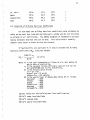
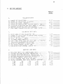
INPUT DATA WORKSHEET
9.
Default
Value
COLLECTOR DAT c,
c:.
,-.'
C2
OF COC-LECTOF:::;; ........ ........ ........ ... .
Nl;MBER 0~ COL~ECTORS IN SERIES .... ~ ........ .... .
~7
COLLECTOR SLOPE CDEGREES) .......
C4
C5
C6
C7
~;Ur1FE':f':
~··· ·······~~···
COLLECTOR ORIENTATION (SQUTH=O~EAST=+~ DES.) ....
CO~LECTOR FLOW RATE PER UN!T AREA (L/CSEC* M2ll ..
PERCENT COLLECTOR LOOP PIR LEAKAGE ........ ..... .
FAN POWER CONSUMPTION PER UNIT AREA IWIM2l ....•.
COLLECTC!R TEST
T
GROSS AREA
T1
T2
NUMBER
T?
F~:-TA!J-A~.. F'HA
T4
FR-·U~-
0~
COLLECTORS IN SERIES WHEN TESTED ..... .
•••••••• .••••.•• ••••.••• •••••
(TEST) ..••..•• ••..•••. .••••..• •
(TE:~:T;·
( VJ / ( ~12:t:C: ·~ )
T6
ANGLE MODIFIER ........ ........ ....... .
COLL. TEST FLOW RATE PER !JNIT ARE~ CL/CSEC*M2> ..
T7
TRANS!~ISSION-ABSORPTION
T~
I ·-'
!~CIDENT
PRODUCT . . . . . . . . . . . . . . . .
RATIO OF APERTURE TO GROSS AREA ........ ....... .
COLLECTOR CHANNEL HEIGHT CMM> •. ~········ ••••..••
., 10 COLLECTOR FLOW CHANNEL LENGTH !M) ........ ...... .
L_4
BUILDING HEAT LOSS COEFFICIE~T CW!Cl ........ ....
MINII'11Y·' DAYTIME BU!l_[IIN13 TEMf''E<;:ATURE iC}.... ....
MINit·1Ut·1 NIGHTII'iE BUILDHKi TEt•iF'EF:r-,TUf::E (C)..... ..
MAX Ir1Ut1 ALLOl•IAE:LE BUILDING TEr~PEF:ATUF:E i Cl. . . . . .
L5
BUILDING THEF:Mr-1L
Lt.
L7
25.
()!)
~
----
00 - - - 10. 1X - - - - -
5.00
----
10.0(! - - - - -
2. i)(i
!. ~ OC:
• 50
-------4, (:\(' - -
·--. 10 - - - - -
----10. oc
•':11-,
~
,,_,
-----
---~-. oc
---• C·(!
HEATING LOAD DATA
''-•
L1
L·C·
L3
----
l..C:O - - - -
D~TA
ONE COJ_LECTOR CM2> .•.•...• •....•..
0~
2C. OCi
CAF'A*::IT~.\!',JCE
~M.J/C)
•••
~
•. , •...
~.
D"'! LY I NTERt>JAL HEAT 13?> H'' 01 ..' /DAY) . . . . . . . . . • . . . . .
HOURLY INTERNAL HEAT GAIN PROFILE (PEPCENTl .....
00
00
00
..::.._1
00
2 . .-,t:"
1 50
4.
3. (:.(I
6. 75
e
._1 •
11
·~·5
10
(:,(I
.
--,
:7:.'5
2 70
"l 60
'
.
.
4''1
.-,
..;:. 40
/:.. 90
C•
,_,.
.
.
(:.. ·:~o
2. 10
~
._r •
4<:.
300.(•0 - - - - ;::·, 0(' - - - - i..O.. ·: 1•) - - - - 22. 00 - - - - 15.00----3C•. 00 - - - - 100.0~
. 00
4
~;(,
ZEROAIR
Version 1.0
User's Manua1
August 1983
Assistance and Information:
K. Ford
Design Aids Engineer
Solar Programs Office
Sir Charles Tupper Building
Riverside Drive
Ottawa KIA OMZ
(613) 998-3641
This document is not a departmental publication.
Do not cite as a reference or catalogue in a library.
User Iesponsibility
Users are responsible for the validity of the information generated by ZEROAIR,
Version 1.0. Consequently the program should not be used by those who do not
comprehend the technical field to which this program applies. Neither Public
Works Canada nor any person acting on behalf of the department makes any
warranty or assumes any responsibility for accuracy, completeness or usefulness
of any information generated by this program.