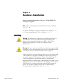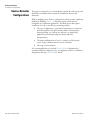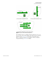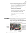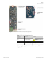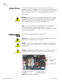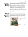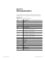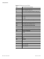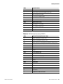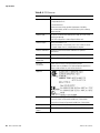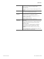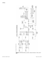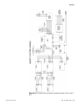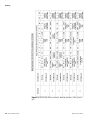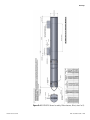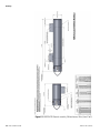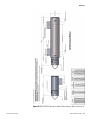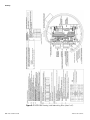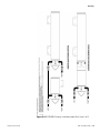
1
Nitus Gamma Backscatter Sensor Installation Guide P/N 717926 Revision A Part of Thermo Fisher Scientific Nitus Gamma Backscatter Sensor Installation Guide P/N 717926 Revision A © 2010 Thermo Fisher Scientific Inc. All rights reserved. “HART” is a registered trademark of the HART Communication Foundation. “FOUNDATION fieldbus” and “Fieldbus Foundation” are registered trademarks of Fieldbus Foundation. All other trademarks are the property of Thermo Fisher Scientific Inc. and its subsidiaries. Thermo Fisher Scientific Inc. (Thermo Fisher) makes every effort to ensure the accuracy and completeness of this manual. However, we cannot be responsible for errors, omissions, or any loss of data as the result of errors or omissions. Thermo Fisher reserves the right to make changes to the manual or improvements to the product at any time without notice. The material in this manual is proprietary and cannot be reproduced in any form without expressed written consent from Thermo Fisher. This page intentionally left blank. Revision History Thermo Fisher Scientific Revision Level Date Comments A 12-2010 Initial release (per ECO 7586). Nitus Installation Guide v This page intentionally left blank. Contents Information & Guidelines .................................................................................. ix Safety Considerations .............................................................................ix Warnings, Cautions, & Notes ................................................................ix Thermo Fisher Scientific Chapter 1 Product Overview ............................................................................................. 1-1 Associated Documentation.................................................................. 1-1 Chapter 2 Handling & Storage .......................................................................................... 2-1 ESD Procedures .................................................................................. 2-1 Unpacking, Inspection, & Storage ...................................................... 2-2 Packing, Shipping, Transporting, & Receiving.................................... 2-2 Chapter 3 Hardware Installation...................................................................................... 3-1 Licensing............................................................................................. 3-1 Source-Detector Configurations.......................................................... 3-2 Guidelines........................................................................................... 3-4 General ............................................................................................ 3-4 System Power Requirements ............................................................ 3-4 Detector-Transmitter .......................................................................... 3-5 Alignment ........................................................................................ 3-6 Measurable Range ............................................................................ 3-7 Remote Mounting of Electronics ..................................................... 3-7 The Source Head ................................................................................ 3-8 Compensation for Small Curvature of Vessel ................................... 3-9 Multiple Detectors / Source Housings............................................... 3-10 Chapter 4 Wiring.................................................................................................................. 4-1 Overview............................................................................................. 4-1 Preparation.......................................................................................... 4-1 Wiring Drawings ............................................................................. 4-2 General Procedure............................................................................... 4-2 The CPU Board .................................................................................. 4-3 Erasing System Memory................................................................... 4-4 AGC and Pre-Amp Boards.................................................................. 4-4 System Power...................................................................................... 4-6 CPU Power Supply Board................................................................ 4-6 AGC Power Supply Board ............................................................... 4-7 Optional EMC Surge Protection Board .............................................. 4-8 Nitus Installation Guide vii Contents Serial Communications ....................................................................... 4-9 RS485 Wiring.................................................................................. 4-9 Initial Setup for Party-Line Communications................................ 4-9 RS232 Wiring................................................................................ 4-10 Using Serial Communications........................................................ 4-10 HART Communications................................................................... 4-10 FOUNDATION Fieldbus Communications ......................................... 4-11 Contact Closure Inputs ..................................................................... 4-11 Current Output ................................................................................ 4-11 Auxiliary Input Wiring...................................................................... 4-12 Cascade Mode Wiring (Level Applications Only).............................. 4-13 Temperature Compensation Wiring (Density Applications Only) .... 4-13 Chapter 5 Service & Support .............................................................................................5-1 Getting Help....................................................................................... 5-1 Warranty............................................................................................. 5-2 Appendix A Ordering Information .......................................................................................A-1 Appendix B Specifications...................................................................................................B-1 Appendix C Drawings............................................................................................................ C-1 Index ..........................................................................................................INDEX-1 viii Nitus Installation Guide Thermo Fisher Scientific Information & Guidelines This section contains information that must be read and understood by all persons installing, using, or maintaining this equipment. Safety Considerations Failure to follow appropriate safety procedures or inappropriate use of the equipment described in this manual can lead to equipment damage or injury to personnel. Any person working with or on the equipment described in this manual is required to evaluate all functions and operations for potential safety hazards before commencing work. Appropriate precautions must be taken as necessary to prevent potential damage to equipment or injury to personnel. The information in this manual is designed to aid personnel to correctly and safely install, operate, and / or maintain the system described; however, personnel are still responsible for considering all actions and procedures for potential hazards or conditions that may not have been anticipated in the written procedures. If a procedure cannot be performed safely, it must not be performed until appropriate actions can be taken to ensure the safety of the equipment and personnel. The procedures in this manual are not designed to replace or supersede required or common sense safety practices. All safety warnings listed in any documentation applicable to equipment and parts used in or with the system described in this manual must be read and understood prior to working on or with any part of the system. Failure to correctly perform the instructions and procedures in this manual or other documents pertaining to this system can result in equipment malfunction, equipment damage, and / or injury to personnel. Warnings, arnings, Cautions, & Notes Warnings, cautions, and notes are used throughout this manual to alert users to potential hazards or important information. Failure to heed the warnings and cautions in this manual can lead to injury or equipment damage. Warning Warnings notify users of procedures, practices, conditions, etc. which may result in injury or death if not carefully observed or followed. The triangular icon displayed with a warning varies depending on the type of hazard (general, electrical, radiation). ▲ Thermo Fisher Scientific Nitus Installation Guide ix Caution Cautions notify users of operating procedures, practices, conditions, etc. which may result in equipment damage if not carefully observed or followed. ▲ Note Notes emphasize important or essential information or a statement of company policy regarding an operating procedure, practice, condition, etc. ▲ x Nitus Installation Guide Thermo Fisher Scientific Chapter 1 Product Overview Refer to the Nitus user guide for descriptions of instrument functions and features. Associated Documentation Thermo Fisher Scientific In addition to this guide, the following documents must be read and understood by all persons installing, using, or maintaining this equipment: ● Nitus for Level and Density Applications, p/n 717925 ● Gamma Radiation Safety, p/n 717904 ● LevelPRO installation manual, p/n 717760 – for transmission applications ● LevelPRO HART® operation manual, p/n 717817 – for HART communications ● LevelPRO with FOUNDATION™ fieldbus application guide, p/n 717915 or DensityPRO with FOUNDATION™ fieldbus application guide, p/n 717917 – for FOUNDATION fieldbus communications Nitus Installation Guide 1-1 This page intentionally left blank. Chapter 2 Handling & Storage This chapter addresses procedures for handling electrostatic discharge (ESD) sensitive equipment, as well as procedures for unpacking, inspecting, and storing of the system. Caution This system is an ESD sensitive instrument. Use proper ESD protective equipment and procedures. Failure to comply with ESD procedures can result in circuit damage. ▲ ESD SD Procedures The instrument contains electronic components that can be damaged from discharges of static electricity: Do not touch the circuit board components. Ordinarily, handling the circuit boards by their edges will not damage the circuits. Observe the following when installing, setting up, servicing, troubleshooting, or repairing the instrument: 1. Use an antistatic bag. Most instrument subassemblies are shipped in a special antistatic bag. When not installed, keep the assembly in the bag as often as possible. 2. Remove ESD sensitive subassemblies only under the following conditions: a. When at a designated static-free workstation or when the bag is grounded at a field site. b. After the conductive area of the container has been neutralized. c. After making firm contact with an antistatic mat and / or firmly gripping a grounded individual. 3. Personnel handling ESD sensitive devices should be neutralized to a static-free workstation by means of a grounding wrist strap that is connected to the station or to a good grounding point at the field site. 4. Do not allow clothing to make contact with ESD sensitive devices. Thermo Fisher Scientific Nitus Installation Guide 2-1 Handling & Storage Unpacking, Inspection, & Storage 5. Avoid touching edge connectors and components. 6. Avoid partially connecting ESD sensitive devices. These devices, especially the power supply connector, can be damaged by floating leads. 7. Ground test equipment. 8. Avoid static charges during troubleshooting. Unpacking, Inspection, & Storage Note Inspection, adjustment, installation, and maintenance of the instrument must be performed by experienced personnel only. ▲ 1. Upon receipt, inspect the instrument for damage that may have occurred while in transit. If there is evidence of rough handling or damage, file a damage claim with the transportation company immediately. Notify Thermo Fisher and / or your sales representative as soon as possible. 2. Carefully inspect the packing material prior to discarding it to ensure that all equipment and instruction paperwork has been removed. 3. Use the original packing material and container for storage if necessary. 4. If storing the instrument, the storage environment should be protected, free from extremes of temperatures and high humidity, and fall within the environmental constraints listed in the specifications. Packing, Shipping, Transporting, & Receiving 2-2 Nitus Installation Guide All personnel involved in the packing, shipping, or receiving of hazardous material must be trained in accordance with the United States Department of Transportation (DOT) and OSHA hazardous materials regulations or in accordance with the Canadian Nuclear Safety Commission (CNSC) regulations. Thermo Fisher Scientific Chapter 3 Hardware Installation Read the Gamma Radiation Safety Guide (p/n 717904) PRIOR TO installing the equipment. Note Copies of the drawings referenced in this manual are provided in Appendix C. ▲ For detector-transmitter housing layout details, refer to drawing 0-0704096. For mounting dimensions, refer to drawing 0-0704-078. Licensing icensing Warning The instrument is a nuclear device regulated by federal and / or state authorities. You are responsible for knowing and following the pertinent safety and regulatory requirements. Refer to the Gamma Radiation Safety Guide (p/n 717904) for a summary of these requirements. ▲ Warning Moving or removing an installed source housing or any assembly that includes a source housing requires a person who is specifically licensed to install and commission Thermo Scientific source housings. ▲ In the United States, your general license permits you to own and install all of the instrument’s components, including the source housing. However, you may not commission the instrument (remove the lock and open the source housing shutter for the first time) without a specific license authorizing radiation commissioning of the instrument. In Canada, you are only allowed to remove the instrument from the shipping container if your CNSC license has a condition authorizing mounting / dismounting of devices. For assistance obtaining a license and / or commissioning / decommissioning the instrument, contact Thermo Fisher. Thermo Fisher Scientific Nitus Installation Guide 3-1 Hardware Installation Source-Detector Configurations Source-Detector Configurations The gauge is comprised of a source head that contains the radioisotope and the detector-transmitter that contains the scintillation detector and electronics. With its multiple source-detector configurations, Nitus provides significant installation flexibility. Figure 3–1 illustrates typical source-detector configurations for different applications. The main factors that require consideration for the source-detector mounting include: ● The type of application – point density measurement, continuous level measurement, both point density and level measurement, density profiling, etc. (At least two detectors are required for applications performing both point density and level measurements.) ● The shape and dimension of vessel – vertical vessel, horizontal vessel, or pipe (diameter must be at least 24 inches). ● The range of measurement. It is recommended that you consult Thermo Fisher to determine the optimal installation configuration for your application. Refer to installation arrangement drawing 0-0704-098 for details. 3-2 Nitus Installation Guide Thermo Fisher Scientific Hardware Installation Source-Detector Configurations Figure 3–1. Typical source-detector configurations The scintillation detector is available in lengths ranging from 1 foot to 12 feet. For a tall or narrow tank, multiple sources and / or detectors might be required. Contact Thermo Fisher for assistance. The specific sourcedetector configuration depends on the application. Refer to installation arrangement drawing 0-0704-098 for details. Thermo Fisher Scientific Nitus Installation Guide 3-3 Hardware Installation Guidelines Guidelines Warning Do not install the system in any hazardous area other than those approved. Refer to the equipment tag for the specific approvals applicable to the configuration of your instrument. ▲ Warning Do not apply power to the instrument in any hazardous area unless the safety ground is properly wired inside the instrument and the cover is properly installed. ▲ Instrument approvals are listed in Appendix B. General Review the following guidelines when planning gauge installation: 1. Ensure the correct power source is available. See “System Power Requirements” later in this chapter. 2. You will need to supply the necessary brackets and hardware required for mounting the gauge to the vessel. 3. There should be enough clearance to install and service the source head and the detector. Refer to the appropriate dimensional drawings in the drawing appendix. 4. Position the source head so the radioactive source identification tag is visible. Mount it so the tag is upright. 5. The gauge should not be mounted where process overflow or other material can collect in the beam path. The source head shutter mechanism must be kept free of debris. 6. If the handheld terminal will be used for configuration, the connection must be located in a safe area. 7. The source head is designed to work up to approximately 1100°C. However, the detector can only work up to 75°C and therefore must be non-contacting for hot vessels. 8. As the measurement is independent of process pressure, there is no limitation on pressure. System stem Power Requirements 3-4 Nitus Installation Guide Ensure the correct power source is available. One of the following input power sources is required: 115 or 230 Vac ± 15%, 50/60 Hz. The maximum power requirement is 12 VA. Thermo Fisher Scientific Hardware Installation Detector-Transmitter DetectoretectorTransmitter Warning Do not install the system in any hazardous area other than those approved. Refer to the equipment tag for the specific approvals applicable to the configuration of your instrument. ▲ Warning Do not apply power to the instrument in any hazardous area unless the safety ground is properly wired inside the instrument and the cover is properly installed. ▲ Warning For hazardous location installations, the cable entries must be sealed per the installation layout drawing 0-0704-096. ▲ Warning For non-hazardous location installations, the enclosure cable entries must be sealed with a compound to protect against the passage of gas or vapors. The sealing compound should not be affected by the surrounding atmosphere or liquids. The sealing compound must have a thickness of at least 5/8” (16 mm). ▲ Warning Use proper lifting procedures during installation to avoid injury. Refer to drawing 0-0704-078 for weights and dimensions of the detector housing. ▲ Figure 3–2. Detector (integrated model) Thermo Fisher Scientific Nitus Installation Guide 3-5 Hardware Installation Detector-Transmitter Alignment Refer to drawings 0-0704-096 and 0-0704-078 for mounting dimensions of the detector-transmitter. The source head and detector are installed on the same side of the vessel. To ensure good measurement sensitivity, it is recommended that the detection area of the detector be symmetric to the source head center (where the source is located), as shown in the figure below. An easy way to ensure proper alignment is to center the two mounting tabs on the detector to the source center. Refer to drawing 0-0704-098 for details. For applications where this symmetric arrangement cannot be achieved (e.g. profiling measurement or limitation on installation space), contact Thermo Fisher for proper arrangement. Figure 3–3. Alignment of detector and source head For horizontal installations, the detector can be mounted above or below the source. For vertical installations, it may be mounted to the left or right. In both cases, the detector must be mounted parallel or tangential to the vessel wall. Refer to drawing 0-0704-098 for details. The standard mounting for Nitus detectors uses angle brackets that are welded on the outer wall of the vessel. The minimum bracket length is determined by the customer insulation thickness and bolt length. Note If welding is not practical, other mounting arrangements are available. Contact Thermo Fisher for assistance. ▲ The Nitus detector can be used with the Thermo Scientific LevelPRO source for transmission measurement. Transmission measurement is normally recommended for pipe applications where the minimum pipe diameter is 24 inches (60.96 cm). Multiple detectors can be used for a large range of measurement. Contact Thermo Fisher for additional information. 3-6 Nitus Installation Guide Thermo Fisher Scientific Hardware Installation Detector-Transmitter Measurable Range Before beginning the installation, verify that the measurable range (the range over which the process level or density can be measured) of the proposed installation meets the requirements of your application. The top and bottom of the measurement range depend on the sourcedetector configuration, detector length, and the position of the source relative to the detector’s detection length. Detection length refers to the part of the detector that senses radiation. Note The detection length of the detector is between the upper mounting bolts and the lower mounting bolts, as shown in installation arrangement drawing 0-0704-098. ▲ Note The Nitus system measures the average density of the area that is between the source and the detector. ▲ Remote Mounting of Electronics For convenience, the transmitter electronics can be mounted separately from the detector. The maximum distance between the electronics and the detector assembly is 50 feet (15.24 m). Conduits that provide good sealing are required for the installation. Refer to installation layout drawing 0-0704-096 for details. Note Remote electronics is standard with the water-cooled option. ▲ Note The gauge must be purchased as a remote unit to have a separate electronics. The integrated unit cannot be broken apart. ▲ Thermo Fisher Scientific Nitus Installation Guide 3-7 Hardware Installation The Source Head The Source Head Warning In the United States, you may uncrate and mount the source housing, but you may not remove the shipping bolt unless you are licensed to commission the gauge. In Canada, you must have a license condition permitting mounting / dismounting, and without this condition, users may not remove the source from the shipping crate. ▲ Warning The Nitus source head weighs approximately 180 lb (81.8 kg). Safety of personnel must be addressed prior to handling. Use proper lifting procedures to avoid injury. ▲ The source head mounting plate is a 12 x 14 inch (4.724 x 5.52 cm) rectangular shape. It has six 0.5” mounting holes on the top and bottom flanges (three per side). It is recommended to have six studs welded on the vessel outer wall for the source head mounting. The stud length needs to be determined by the diameter of the vessel. Unistruts can also be used to hold the source head, especially under circumstances when the point of measurement interest might change. The exact mounting method will vary depending on the application. Figure 3–4. Source head It is extremely important to have the source head in direct contact with the vessel outer wall, so any insulation layers on the vessel must be removed. The source needs to be installed securely, since any movement or change in alignment can affect the gauge’s calibration. 3-8 Nitus Installation Guide Thermo Fisher Scientific Hardware Installation The Source Head Compensation for Small Curvature of Vessel For small diameter vessels, it may be necessary to compensate the curvature of the vessel outer wall to ensure measurement accuracy. The standard method of compensation is to use angled shims. As shown in the figure below, two angled shims are installed under the source head mounting plate on both sides to block unwanted flux. Shim Vessel wall Figure 3–5. Using shims for vessel curvature compensation The need for compensation is determined when the source head is ordered. Typically, shims are required if the vessel OD is less than 8 feet (2.44 m). Thermo Fisher Scientific Nitus Installation Guide 3-9 Hardware Installation Multiple Detectors / Source Housings Multiple Detectors / Source Housings Certain applications may require the use of multiple detectors and / or multiple source heads to span the desired measurable range. If multiple sources and detectors are used for continuous level measurement for a large span, the uppermost unit should be mounted so that the top of its detection length is even with the top of the measurable range. The remaining units should be mounted so that the top of each detector’s detection length is aligned with or slightly overlaps the bottom of the detection length of the detector mounted just above it. A maximum of eight detectors can be daisy-chained together, allowing for a level measurement span of up to 32 feet (9.75 m). Note It is practical to space the pairs so that there is minimum interference between subsequent pairs. Consult Thermo Fisher for assistance. ▲ If one source and multiple detectors are used for density profiling measurement, position the detectors around the source as closely as possible to ensure good sensitivity. Improved profiling resolution can be achieved by adding detectors to the system. Drawing 0-0704-098 provides mounting dimensions for several configurations. 3-10 Nitus Installation Guide Thermo Fisher Scientific Chapter 4 Wiring Overview erview Wiring should be performed in the following order: 1. Power to the gauge 2. Remote computer terminal or HHT to the gauge via the serial communication ports 3. Optional wiring: a. 4–20 mA current output b. Contact closure inputs c. Remote display d. Auxiliary 4–20 mA current input e. FOUNDATION fieldbus f. EMC surge protection option g. Wiring to cascade multiple units (level applications only) h. Temperature compensation (density applications only) Preparation Review the following carefully prior to connecting any wiring. Warning Remove all power from the unit before making any connections. Electrocution can result if power is present. ▲ Warning All wiring must be done by qualified individuals in accordance with applicable codes such as the NEC (National Electric Code) ANSI / NFPA 70 specifications or the Canadian Electrical Code Part 1. ▲ Warning Do not apply power to the unit in any hazardous area unless the safety ground is properly wired inside the unit and the cover is properly installed. ▲ Thermo Fisher Scientific Nitus Installation Guide 4-1 Wiring General Procedure Warning For hazardous location installations, the cable entries must be sealed per the installation layout drawing 0-0704-096. ▲ Warning For non-hazardous location installations, the cable entries into the enclosure must be sealed with a compound to protect against the passage of gas or vapors. The sealing compound should not be affected by the surrounding atmosphere or liquids. The sealing compound must have a thickness of at least 5/8” (16 mm). ▲ Warning If metal conduit is used, the conduit must be grounded. ▲ Warning Connect the AC wiring earth ground to the internal safety ground terminal, as shown in the wiring diagram. ▲ Wiring iring Drawings The installation layout drawing 0-0704-096 provides general guidance for routing the cables to the unit. The installation wiring drawing 0-0704-095 shows the function of each connector pin on the CPU board and power board. In addition, the drawing shows cable requirements for connecting the sensor to the transmitter, power requirements, and grounding locations. The label on the top of the detector-transmitter chassis also shows connector pin information for wiring the power boards, including the contact closure inputs and the current output. It provides instructions for wiring the RS485 and RS232 serial port connectors. Additional instructions for wiring of the FOUNDATION fieldbus connectors are also shown in drawing 0-0704-095. General Procedure Follow this general procedure to access the detector electronics for wiring. 1. Ensure all source housing shutters are in the OFF position. 2. Ensure all power to the gauge is turned off. 3. Remove the housing access cover by loosening the screw on the cover retaining bracket and sliding the bracket off of the housing cover. Unscrew the housing access cover. Two lugs on the top of the cover aid with removal. 4-2 Nitus Installation Guide Thermo Fisher Scientific Wiring The CPU Board 4. Remove the cable conduit plugs from the hole(s) that will be used. As shown in installation layout drawing 0-0704-096, lay one conduit for the power cables and a second conduit for signal cables, if applicable. Route the cables into the detector housing and connect input power and signal wires as shown in wiring drawing 0-0704-095. 5. The ground line of the AC input power needs to be connected to the internal safety ground lug of the Nitus housing. 6. Pull each cable through the correct conduit fitting and into the enclosure. Leave approximately 6 inches (150 mm) for strain relief. Secure the conduit, making sure it is completely sealed. 7. Continue through the remaining sections in this chapter for wiring instructions specific to the power supply, serial and HART communications, etc. 8. When the wiring is complete, replace the detector housing cover, and secure the cover retaining bracket. The CPU Board The CPU board is the system’s main board. The gauge is shipped from the factory with all CPU jumpers configured properly for your system configuration. Should you need to replace the CPU board, note the jumper settings for connectors J7 (current output configuration) and J11 (system configuration) before replacing the board. After installing the new board, verify that the jumpers are set properly for your system configuration. Figure 4–1 shows the location of connectors and jumpers. Figure 4–1. Connectors and jumpers on the CPU board Thermo Fisher Scientific Nitus Installation Guide 4-3 Wiring AGC and Pre-Amp Boards Erasing ing System Memory Move the jumper to pins 1 and 8 of the J11 connector to erase system memory. Caution Placing a jumper across pins 1 and 8 on the J11 connector erases system memory. All user-entered parameters are erased and reset to factory defaults. ▲ If you are going to erase memory by placing a jumper across pins 1 and 8, first remove power from the detector-transmitter. Note the location of the jumpers on the J11 connector. Place a jumper across pins 1 and 8, apply power, and leave power on for approximately 30 seconds to erase memory. Remove power and restore the configuration jumpers to their original settings. AGC and PreAmp Boards The instrument is equipped with an Automatic Gain Control (AGC) adaptive system. The fundamental principle of AGC is that the average output signal level will be fed back to adjust the gain to an appropriate level for a range of input signal levels. AGC is used to adjust the voltages applied to the photomultiplier tubes (PMTs) to control the system for optimal performance. The pre-amp board picks up the PMT pulse signals and amplifies the working pulses. Note The gauge is shipped from the factory with the AGC and pre-amp boards configured properly for your system. If replacement becomes necessary, consult Thermo Fisher before removing the board from the system. ▲ Warning Remove all power from the unit before making any connections. Electrocution can result if power is present. ▲ 4-4 Nitus Installation Guide Thermo Fisher Scientific Wiring AGC and Pre-Amp Boards Figure 4–2. Connectors on the AGC (left) and pre-amp (right) boards Table 4–1. AGC and Pre-Amp board connections AGC Board Connector Connects to J10 J2 on pre-amp board J11 J1 on pre-amp board J9 J2 on AGC power supply board Comment Caution High voltages are present at these terminals. Power input Refer to wiring drawing 0-0704-056 for cable information and other wiring details. Thermo Fisher Scientific Nitus Installation Guide 4-5 Wiring System Power System Power The system is designed to operate on 115 or 230 Vac (± 15%). The maximum input power requirement is 12 VA. The maximum length of the cable that can be used to supply power varies depending on the wire gauge. Refer to wiring drawing 0-0704-056 for cable information and other wiring details. Warning All wiring must be done by qualified individuals in accordance with applicable codes such as the NEC (National Electric Code) ANSI / NFPA 70 specifications or the Canadian Electrical Code Part 1. For intrinsically safe systems, refer to ANSI / ISA RP 12.6. ▲ Note To meet the requirements of CSA 1010.1, an external switch or circuit breaker must be installed to allow the power source to be disconnected from the gauge. In addition, protective bonding (grounding) must always be provided. ▲ CPU U Power Supply Board The CPU power supply (PS) board is shown below. Warning Remove all power from the unit before making any connections. Electrocution can result if power is present. ▲ Caution The AC selector switch is shown in the figure below. Applying 230 Vac with the selector switch in the 115 Vac position will damage the equipment. ▲ Caution For reliable operation and to maintain safety approval, the fuse on the CPU PS board must only be replaced with an approved fuse. ▲ Figure 4–3. CPU power supply board 4-6 Nitus Installation Guide Thermo Fisher Scientific Wiring System Power Table 4–2. CPU power supply board connections CPU PS Board Connector Connects to J17 Power input J3 J9 on CPU board J1 J1 on AGC power supply board Comment Power to CPU board For additional details, refer to wiring drawing 0-0704-056. AGC C Power Supply Board The AGC power supply (PS) board is shown below. Warning Remove all power from the unit before making any connections. Electrocution can result if power is present. ▲ Caution The AC selector switch is shown in the figure below. Applying 230 Vac with the selector switch in the 115 Vac position will damage the equipment. ▲ Caution For reliable operation and to maintain safety approval, the fuse on the AGC PS board must only be replaced with an approved fuse. ▲ Figure 4–4. AGC power supply board Thermo Fisher Scientific Nitus Installation Guide 4-7 Wiring Optional EMC Surge Protection Board Table 4–3. AGC power supply board connections AGC PS Board Connector Connects to Comment J1 J1 on CPU power supply board Power input J2 J9 on AGC board Power to AGC board For additional details, refer to wiring drawing 0-0704-056. Optional EMC Surge Protection Board To eliminate the possibility of unwanted electromagnetic signals either going from Nitus into other customer equipment or from other customer equipment into Nitus, an EMC protection system has been developed. J3 is the connector to the J3, J10, and J13 on the CPU board. J4 on the surge protection board is connected to the TB1 on the top of the electronics chassis, which is designed for customer wiring. Refer to drawings 0-0704-056 and 0-0704-095 in the drawing appendix for the wiring requirements. Figure 4–5. Connectors on the optional EMC surge protection board 4-8 Nitus Installation Guide Thermo Fisher Scientific Wiring Serial Communications Serial Communications The gauge provides one RS232 single drop and one RS485 multi-drop serial interface. Screw terminal connectors for both ports are located at J3 on the CPU board. The RS485 connector includes the +8 Vdc required to power the Thermo Scientific 9734 handheld terminal (HHT) as well as the +DATA and –DATA connections. An RJ11 (phone jack) connector is also provided for the RS485 port at J4 on the CPU board. The HHT can be connected directly to the RJ11 connector in safe areas. Both ports provide independent access to the measurement readings and software functions. They are always active and can be used to display measurements. The setup menus, however, may only be accessed by one port at a time. RS485 Wiring Connecting the serial (COM) port on a PC to the RS485 port on the gauge requires the RS485/RS232 converter (p/n OTO515D). 1. Connect J3-12 (+DATA) and J3-11 (–DATA) to the corresponding connections on the RS485/RS232 converter. 2. Connect the converter to the PC using the supplied DB9 serial cable. 3. Refer to drawings 0-0704-056 and 0-0704-095 for additional details. Initial Setup for PartyLine Communications To communicate with multiple gauges via a RS485 party-line, each unit must be assigned a unique unit identification number so it can be addressed individually. All gauges are assigned unit number 0 (zero) by default. To assign a unique unit number to each gauge, you must be able to communicate with each one individually. Disconnect each gauge from the party-line in turn and communicate with the disconnected gauge directly. Alternately, you can remove power from all gauges except one and assign a unit number to the powered gauge. If you have trouble using another device on the RS485 chain, verify that it is properly terminated for its position on the chain. To terminate a device, connect a 120-ohm resistor between its RS485 + / - data terminals. Never terminate more than the first and last device in the chain. Thermo Fisher Scientific Nitus Installation Guide 4-9 Wiring HART Communications RS232 Wiring The serial port on a PC (COM1 or COM2) can be connected directly to the RS232 port on the gauge. This requires five wires: ground, transmit (TX), receive (RX), request-to-send (RTS), and clear-to-send (CTS). The connections between the RS232 port (J3 on the CPU board) and the PC serial port are summarized in the table below for standard DB9 and DB25 PC serial port connectors. Figure 4–6. Using Serial Communications J3 on CPU Board PC Serial Port DB9 Connector PC Serial Port DB25 Connector J3-2 (RX) Pin 3 Pin 2 J3-3 (TX) Pin 2 Pin 3 J3-4 (RTS) Pin 8 Pin 5 J3-5 (CTS) Pin 7 Pin 4 J3-6 (GND) Pin 5 Pin 7 To communicate with the gauge from a PC requires that the PC be running a terminal emulation software. The default communication settings for the gauge’s RS485 and RS232 ports and for the HHT are: 7 data bits, Even parity, 1 stop bit, 9600 baud. Refer to the Nitus user guide for additional details about setting up and using serial communications. HART Communications The HART communication protocol is supported over the 4–20 mA current output with the HART interface board. The HART interface board is an optional daughter board that is wired via a cable to J6 on the CPU board. Communication with the gauge is via the 275 or 375 Field Communicator from Emerson Electric Co. Refer to the LevelPRO HART operation manual (p/n 717817). Note HART communication protocol allows you to configure and calibrate the gauge in most applications; however, due to limitations of the protocol, the complete range of functions is only available when using the Thermo Scientific Model 9734 handheld terminal and the RS485 port. ▲ 4-10 Nitus Installation Guide Thermo Fisher Scientific Wiring Foundation Fieldbus Communications FOUNDATION Fieldbus Communications Contact Closure Inputs The FOUNDATION fieldbus communication protocol is supported over connector TB2 on the top of the electronics chassis. The interface board is an optional daughter board that is wired via a cable to J6 on the CPU board. Communication with the gauge is via the 375 or 475 Field Communicator from Emerson Electric Co. Refer to the LevelPRO with FOUNDATION fieldbus application guide (p/n 717915) or the DensityPRO with FOUNDATION fieldbus application guide (p/n 717917) for detailed instructions. The contact closure inputs are dry contact inputs between ground and Switch 1 and ground and Switch 2 at J13 on the CPU board. The gauge can be configured via software settings to execute a command or other function upon a user-provided contact opening or closing. Refer to the Nitus user manual for instructions on assigning commands to the contact closure inputs. When operating in “cascade” mode, where multiple units are wired together to act as a single detector, contact closure Switch 2 is dedicated to performing the cascading function. Refer to drawings 0-0704-056 and 0-0704-095. Current Output Following are the configurations available for the 4–20 mA current output: ● Isolated, loop-powered (default) ● Non-isolated, self-powered ● Isolated, self-powered output (requires optional piggyback board p/n 886595-1) All three configurations can drive an 800 ohm maximum load over the full current output range. The current output is programmable between 3.8 and 20.5 mA. The fault low condition for the current output is 3.6 mA or less, and the fault high condition is 20.8 mA or greater. The default current output configuration is isolated, loop-powered. A jumper is placed across pins 4 and 5 of the J7 connector on the CPU board. For this configuration, pins 6 and 7 of the J10 connector are for the 4–20 mA output connections. Thermo Fisher Scientific Nitus Installation Guide 4-11 Wiring Auxiliary Input Wiring Figure 4–7. 4–20 mA loop powered configuration To configure the current output as non-isolated, self-powered, move the jumper to pins 3 and 4 of the J7 connector. For this configuration, pins 6 and 9 of the J10 connector are for the 4–20 mA output connections. Figure 4–8. 4–20 mA non-isolated, self-powered configuration To configure the current output as isolated, self-powered, a piggy-back board must be installed on the J7 connector (no jumpers used). For this configuration, pins 6 and 8 of the J10 connector are for the 4–20 mA output connections. Auxiliary Input Wiring 4-12 Nitus Installation Guide There is an auxiliary connection on connector J10 for applications requiring an outside 4–20 mA signal be input into the Nitus and used as a form of compensation adjustment (vapor density, pressure, etc.). The outside 4–20 mA signal should be wired so that the positive connection of the loop is connected at J10 pin 1 and the negative side connected to J10 pin 2. The special equation is then utilized to incorporate this input into the Nitus program. Refer to the Nitus user guide for information on special equations. Thermo Fisher Scientific Wiring Cascade Mode Wiring (Level Applications Only) Cascade Mode Wiring (Level Applications Only) For applications requiring a detector length greater than 12 feet (3.66 m), up to eight units can be wired together to act as one continuous detector. In this situation, the last unit in the line is referred to as the primary unit. All wiring for the serial ports, relays, etc. is done in the primary unit. Remaining units are referred to as secondary units. All secondary units must be powered in the same manner as the primary unit. Each secondary unit must be wired such that the cascade “out” from one goes into the cascade “in” of the next unit in line. These totaled signals are accumulated in the primary unit, which outputs the actual level indication. All programming for secondary units must be set at default conditions for the cascade to work properly. Refer to drawings 0-0704-056 and 0-0704-095 in the drawing appendix for the wiring requirements. Temperature Compensation Wiring (Density Applications Only) For applications that require temperature compensation, the instrument can accept a temperature input to compensate the density measurement for changes in process temperature. This requires the Thermo Scientific temperature compensation board (p/n 886609), which is shown below. Refer to drawings 0-0704-056 and 0-0704-095 for additional details. Figure 4–9. Temperature compensation board Thermo Fisher Scientific Nitus Installation Guide 4-13 This page intentionally left blank. Chapter 5 Service & Support Getting Help The local representative is your first contact for support and is well equipped to answer questions and provide application assistance. You can also obtain support by contacting Thermo Fisher directly. Process Instruments 14 Gormley Industrial Avenue Gormley, Ontario L0H 1G0 CANADA Unit 702-715, 7/F Tower West Yonghe Plaza No. 28 Andingmen East Street, Beijing 100007 CHINA +1 (800) 437-7979 +1 (713) 272-0404 direct +1 (713) 4573 fax +1 (905) 888-8808 +1 (905) 888-8828 fax +86 (10) 8419-3588 +86 (10) 8419-3580 fax A-101, 1CC Trade Tower Senapati Bapat Road Pune 411 016 Maharashtra, INDIA Ion Path, Road Three Winsford, Cheshire CW7 3GA UNITED KINGDOM 1410 Gillingham Lane Sugar Land, TX 77478 USA +91 (20) 6626 7000 +91 (20) 6626 7001 fax +44 (0) 1606 548700 +44 (0) 1606 548711 fax www.thermoscientific.com Thermo Fisher Scientific Nitus Installation Guide 5-1 Service & Support Warranty Warranty Thermo Scientific products are warranted to be free from defects in material and workmanship at the time of shipment and for one year thereafter. Any claimed defects in Thermo Scientific products must be reported within the warranty period. Thermo Fisher Scientific Inc. (Thermo Fisher) shall have the right to inspect such products at Buyer’s plant or to require Buyer to return such products to Thermo Fisher plant. In the event Thermo Fisher requests return of its products, Buyer shall ship with transportation charges paid by the Buyer to Thermo Fisher plant. Shipment of repaired or replacement goods from Thermo Fisher plant shall be F.O.B. Thermo Fisher plant. A quotation of proposed work will be sent to the customer. Thermo Fisher shall be liable only to replace or repair, at its option, free of charge, products which are found by Thermo Fisher to be defective in material or workmanship, and which are reported to Thermo Fisher within the warranty period as provided above. This right to replacement shall be Buyer’s exclusive remedy against Thermo Fisher. Thermo Fisher shall not be liable for labor charges or other losses or damages of any kind or description, including but not limited to, incidental, special or consequential damages caused by defective products. This warranty shall be void if recommendations provided by Thermo Fisher or its Sales Representatives are not followed concerning methods of operation, usage and storage or exposure to harsh conditions. Materials and / or products furnished to Thermo Fisher by other suppliers shall carry no warranty except such suppliers’ warranties as to materials and workmanship. Thermo Fisher disclaims all warranties, expressed or implied, with respect to such products. EXCEPT AS OTHERWISE AGREED TO IN WRITING BY Thermo Fisher, THE WARRANTIES GIVEN ABOVE ARE IN LIEU OF ALL OTHER WARRANTIES, EXPRESSED OR IMPLIED, AND Thermo Fisher HEREBY DISCLAIMS ALL OTHER WARRANTIES, INCLUDING THOSE OF MERCHANTABILITY AND FITNESS FOR PURPOSE. 5-2 Nitus Installation Guide Thermo Fisher Scientific Appendix A Ordering Information A complete Nitus system consists of any number of integrated detectortransmitter(s) and sources as applicable to the application, and a type of communication. Table A–1. 6000 series gamma source head Thermo Fisher Scientific Code Vessel Orientation H Horizontal V Vertical Code Vessel Outer Diameter XXXX Vessel outer diameter in ft (minimum 2.0 ft) Code Source Type and Size CS10 10 mCi/270 MBq Cs-137 stainless steel, doubly encapsulated, Special Form certified from a Competent Authority CS20 20 mCi/740 MBq Cs-137 stainless steel, doubly encapsulated, Special Form certified from a Competent Authority CS50 50 mCi/1.85 GBq Cs-137 stainless steel, doubly encapsulated, Special Form certified from a Competent Authority CS100 100 mCi/3.7 GBq Cs-137 stainless steel, doubly encapsulated, Special Form certified from a Competent Authority Code Source Housing Material CS Carbon steel SS Stainless steel Code Actuators S Standard manual handle Code Temperature H < 600°C Code Mounting Pattern S Standard 4 corner hole Nitus Installation Guide A-1 Ordering Information Table A–2. IP2010 detector for level (IP2010L) A-2 Nitus Installation Guide Code Detector/Transmitter Enclosure Type CS Carbon steel detector, CSA/US, ATEX SS Stainless steel detector, CSA/US, ATEX CW Carbon steel water-cooled jacketed steel detector, CSA/US, ATEX SW Stainless steel water-cooled jacketed steel detector, CSA/US, ATEX Code ECC Option N No selection E1 ECC – 1 μCu E2 ECC – 2 μCu Code Carbon Steel Detector/Transmitter Length 00 to 12 00 = no selection, 01 to 12 for lengths 1 ft to 12 ft Code Carbon Steel Water-Cooled Detector/Transmitter Length 00 to 12 00 = no selection, 01 to 12 for lengths 1 ft to 12 ft Code Stainless Steel Detector/Transmitter Length 00 to 12 00 = no selection, 01 to 12 for lengths 1 ft to 12 ft Code Stainless Steel Water-Cooled Detector/Transmitter Length 00 to 12 00 = no selection, 01 to 12 for lengths 1 ft to 12 ft Code Electronics Packaging Type I Integrated R Remote Code Input Power A 115 Vac B 230 Vac Code Certification C CSA/CUS A ATEX Code 4–20 mA Output Type L Isolated, loop-powered S Isolated, self-powered N Non-isolated, self-powered Thermo Fisher Scientific Ordering Information Code Communications N No selection A Thermo Scientific 9734 HHT RS485 & RS232 cable B HART communication module C FOUNDATION fieldbus module D 9734 HHT RS485 & RS232 cable with HART E 9734 HHT RS485 & RS232 cable with FOUNDATION fieldbus Code Optional Accessories L Lg SS tag (3.3” x 2.5”) wired R RJ-11 modular connector jack D Thermo Scientific Model 9723 backlit LCD A 3/4" NPT to metric adapter Table A–3. IP2010 detector for density (IP2010D) Thermo Fisher Scientific Code Detector/Transmitter Enclosure Type CS Carbon steel detector, CSA/US, ATEX SS Stainless steel detector, CSA/US, ATEX CW Carbon steel water-cooled jacketed steel detector, CSA/US, ATEX SW Stainless steel water-cooled jacketed steel detector, CSA/US, ATEX Code Input Power A 115 Vac B 230 Vac Code 4–20 mA Output Type S Isolated, self-powered Code Electronics Packaging Type I Integrated R Remote Code Certification C CSA/CUS A ATEX Code Temperature Compensation N No selection T Temperature compensation board Nitus Installation Guide A-3 Ordering Information A-4 Nitus Installation Guide Code Communications N No selection A Thermo Scientific 9734 HHT RS485 & RS232 cable B HART communication module C FOUNDATION fieldbus module D 9734 HHT RS485 & RS232 cable with HART E 9734 HHT RS485 & RS232 cable with FOUNDATION fieldbus Code Optional Accessories L Lg SS tag (3.3” x 2.5”) wired R RJ-11 modular connector jack D Thermo Scientific Model 9723 backlit LCD A 3/4" NPT to metric adapter Thermo Fisher Scientific Appendix B Specifications Results may vary under different operating conditions. Table B–1. System performance specifications Level measurement 0.5% of span, target density should be between 0 and 3 g/cc Density measurement From ± 0.0001 g/cc depending on application; density range 0–3 g/cc Table B–2. Gamma ray source Thermo Fisher Scientific Source name 6000 series Source type Cs-137 stainless steel, doubly encapsulated Size 10–1000 mCi Cs-137 (source size dependent upon application) Source housing Carbon steel or stainless steel construction with tungsten core Two-position rotary shutter, lockable in open and closed positions. ANSI/HPS rating ANSI-94-554-565-R6 Fire proof rating Fire proof, passed 2000 °F (1093 °C) testing for 4 hours Vibration test MIL 810F, Method 514.6, Transportation Reliability Shutter tested for 1 million cycles with no failures Shock test Multiple drops from 1 meter height on concrete surface Weight 180 lb (81.8 kg) Size 12 x 14 in (4.724 x 5.52 cm) Mounting Source head designed to match vessel radius. Standard 4 corner hole feature for ease of mounting. Source head must be in contact with actual vessel wall. Will not work over insulation. No air gap allowed. A minimum vessel diameter of 2 ft required. Nitus Installation Guide B-1 Specifications Table B–3. IP2010 detector Detector name IP2010 System architecture Available in two options: - Integrated electronics - Remote electronics Surface mount technology provides high degree of reliability. All user data doubly stored in non-volatile memory with no battery backup required. Detection type PVT plastic scintillator with wide dynamic range. PVT resists shock and moisture damage. Dual PMT configuration to reduce Signal-to-Noise ratio. Detector lengths Density measurement: 2 ft Level measurement: 1 ft increments, from 1 to 4 ft with one source. For lengths longer than 4 ft, multiple detectors required. Detector stabilization Electronic control without heater stabilization for optimum performance. Power 120/230 Vac, 50-60 Hz, 500 mA max Operating temperature -40°C to +75°C (-40°F to 167°F) ambient Enclosure construction Carbon steel or stainless steel polyurethane painted. Optional water-cooled detector for higher temperature applications. Water-cooled available only with remote electronics. Approvals Current outputs 4–20 mA isolated, loop-powered into 800 ohms, field scalable 4–20 mA isolated, self-powered into 800 ohms, field scalable 4–20 mA non-isolated self-powered into 800 ohms, field scalable B-2 Nitus Installation Guide Serial outputs RS485 half duplex; RS232 full duplex Contact closure outputs Two – 115 Vac/28 Vdc SPDT @ 10 amps (230 Vac SPDT @ 8 A) Thermo Fisher Scientific Specifications Inputs Signal from another Thermo Scientific LevelPRO detector. Additional input for gas density compensation or buildup available. Dry contact closure. Temperature compensation circuitry with 100 ohm platinum RTD 2 or 3-wire Mounting hardware Integral bolt-on bracket. Can be mounted up to 6” from the vessel wall. Insulation allowed between detector and wall. Thermo Scientific Model 9723 Local remote display. Backlit LCD with two lines, 16 alphanumeric characters. Hazardous enclosure is FMRC and CSA approved: Class I, Div. 1, Groups E, F, G; Class III, Div. 1. Display powered from electronics. Maximum separation from electronics 300 ft (91.4 m). Programming Menu driven Emerson 375/475 Field Communicator: For gauge configuration and calibration. Communicates with any Nitus via the current loop. BEL202FSK standard. Thermo Scientific HHT: For gauge configuration and calibration. Communicates with any Nitus via RS485 connector. Provides upload/download of gauge configuraiton to/from PC via RS232 interface. Comm PC interface software: For interfacing with up to 32 Nitus units over RS485. RS485/RS232 converter provided. Thermo Fisher Scientific Nitus Installation Guide B-3 This page intentionally left blank. Appendix C Drawings Note Information presented in this chapter has been regenerated from original drawings. Every effort is made to maintain document accuracy. However, in order to enhance legibility, the documents may have been restructured and some information may have been intentionally excluded. Therefore, the drawings within this manual may not be exact duplicates of the original drawings. ▲ Note Drawings in this manual are included for reference only and may not be the current version. Contact the factory if you need a copy of the latest revision. ▲ Table C–1. Thermo Fisher Scientific Drawing Rev. Description Page 0-0704-056 A Wiring schematic, detector electronics, Nitus C–2 0-0704-078 A General assembly, EXd enclosures, Nitus C–5 0-0704-095 A Drawing, installation wiring, Nitus C–8 0-0704-096 A Drawing, installation layout, Nitus C–9 0-0704-097 A Schematic, cascade wiring, Nitus C–10 0-0704-098 A Drawing, installation arrangement, Nitus C–11 Nitus Installation Guide C-1 Drawings Figure C–1. 0-0704-056: Wiring schematic, detector electronics, Nitus (sheet 1 of 3) C-2 Nitus Installation Guide Thermo Fisher Scientific Drawings Figure C–2. 0-0704-056: Wiring schematic, detector electronics, Nitus (sheet 2 of 3) Thermo Fisher Scientific Nitus Installation Guide C-3 Drawings Figure C–3. 0-0704-056: Wiring schematic, detector electronics, Nitus (sheet 3 of 3) C-4 Nitus Installation Guide Thermo Fisher Scientific Drawings Figure C–4. 0-0704-078: General assembly, EXd enclosures, Nitus (sheet 1 of 3) Thermo Fisher Scientific Nitus Installation Guide C-5 Drawings Figure C–5. 0-0704-078: General assembly, EXd enclosures, Nitus (sheet 2 of 3) C-6 Nitus Installation Guide Thermo Fisher Scientific Drawings Figure C–6. 0-0704-078: General assembly, EXd enclosures, Nitus (sheet 3 of 3) Thermo Fisher Scientific Nitus Installation Guide C-7 Drawings Figure C–7. 0-0704-095: Drawing, installation wiring, Nitus (sheet 1 of 1) C-8 Nitus Installation Guide Thermo Fisher Scientific Drawings Figure C–8. 0-0704-096: Drawing, installation layout, Nitus (sheet 1 of 1) Thermo Fisher Scientific Nitus Installation Guide C-9 Drawings Figure C–9. 0-0704-097: Schematic, cascade wiring, Nitus (sheet 1 of 1) C-10 Nitus Installation Guide Thermo Fisher Scientific Drawings Figure C–10. 0-0704-098: Drawing, installation arrangement, Nitus (sheet 1 of 7) Thermo Fisher Scientific Nitus Installation Guide C-11 Drawings Figure C–11. 0-0704-098: Drawing, installation arrangement, Nitus (sheet 2 of 7) C-12 Nitus Installation Guide Thermo Fisher Scientific Drawings Figure C–12. 0-0704-098: Drawing, installation arrangement, Nitus (sheet 3 of 7) Thermo Fisher Scientific Nitus Installation Guide C-13 Drawings Figure C–13. 0-0704-098: Drawing, installation arrangement, Nitus (sheet 4 of 7) C-14 Nitus Installation Guide Thermo Fisher Scientific Drawings Figure C–14. 0-0704-098: Drawing, installation arrangement, Nitus (sheet 5 of 7) Thermo Fisher Scientific Nitus Installation Guide C-15 Drawings Figure C–15. 0-0704-098: Drawing, installation arrangement, Nitus (sheet 6 of 7) C-16 Nitus Installation Guide Thermo Fisher Scientific Drawings Figure C–16. 0-0704-098: Drawing, installation arrangement, Nitus (sheet 7 of 7) Thermo Fisher Scientific Nitus Installation Guide C-17 This page intentionally left blank. Index 4 4-20 mA current output configuration, 4-11–4-12 A AGC board, 4-4–4-5 AGC power supply board, 4-7–4-8 Automatic Gain Control (AGC) board, 4-4–4-5 auxiliary current input, 4-12 C Canadian Nuclear Safety Commission (CNSC), 2-2, 3-1 Canadian Standards Association (CSA), 4-6 cascade mode, 4-11, 4-13 CNSC. See Canadian Nuclear Safety Commission. commissioning, 3-1, 3-8 communications handheld terminal (HHT), 4-9–4-10 HART protocol, 4-10 RS232 serial port, 4-9–4-10 RS485 serial port, 4-9–4-10 wiring and connections, 4-9–4-10 contact closure input, 4-11 contact information, 5-1 CPU board jumper settings, 4-3–4-4 erasing system memory, 4-4 CPU power supply board, 4-6–4-7 CSA. See Canadian Standards Association. D Department of Transportation, 2-2 detector-transmitter accessing detector electronics, 4-2–4-3 determining sensitive length, 3-7 installation, 3-5–3-7 system ordering information, A-1–A-4 Thermo Fisher Scientific DOT. See Department of Transportation. E electrostatic discharge (ESD), 2-1–2-2 EMC surge protection board, 4-8 ESD. See electrostatic discharge F FOUNDATION fieldbus board, 4-11 H handheld terminal (HHT), 3-4, 4-1, 4-10 handling the instrument, 2-1–2-2 hardware installation, 3-1–3-10 HART, 4-10 hazardous locations, 3-5 HHT. See handheld terminal. I I/O. See inputs, outputs. inputs auxiliary current, 4-12 contact closure, 4-11 installation commissioning, 3-1 detector-transmitter, 3-5–3-7 determining measurable range, 3-7 determining source beam alignment, 3-6 drawings, C-1–C-17 hardware, 3-1–3-10 hazardous locations, 3-5 multiple detectors/source housings, 3-10 planning, 3-4 remote mounting of electronics, 3-7 safety, 3-1, 3-4, 3-5 source housing, 3-8 system power requirements, 3-4 Nitus Installation Guide INDEX-1 Index system wiring, 4-1–4-13 installing commissioning, 3-1 detector-transmitter, 3-5 determining measurable range, 3-7 determining source beam alignment, 3-6 drawings, C-1–C-17 guidelines, 3-4 hardware, 3-1–3-10 in hazardous locations, 3-5 multiple detectors/source housings, 3-10 planning, 3-4 remote mounting of electronics, 3-7 safety, 3-1, 3-4, 3-5 source housing, 3-8 system power requirements, 3-4 system wiring, 4-1–4-13 power supply, 4-6 AGC power supply board, 4-7–4-8 CPU power supply board, 4-6–4-7 pre-amp board, 4-4–4-5 R radiation beam. See source. receiving the instrument. See handling the instrument. remote electronics, 3-7 RS232 serial port wiring and connections, 4-9–4-10 RS485 serial port party-line setup, 4-9 wiring and connections, 4-9–4-10 S licensing, 3-1, 3-8 safety, ix–x, 3-1, 3-4, 3-5, 4-1, 4-2, 4-6 shipping the instrument. See handling the instrument. source aligning the beam, 3-6 mounting the source housing, 3-4, 3-8 specifications, B-1–B-3 storage. See handling the instrument. storing. See handling the instrument. M U Model 9734. See handheld terminal (HHT). mounting. See installing or installation. unpacking. See handling the instrument. J jumper settings CPU board, 4-3–4-4 L W O ordering information, A-1–A-4 OSHA, 2-2 outputs 4-20 mA current, 4-11–4-12 P party-line communications, 4-9 power system requirements, 3-4 INDEX-2 Nitus Installation Guide wiring, 4-1–4-13 AGC power supply board, 4-7–4-8 auxiliary current input, 4-12 cascade mode, 4-13 communications, 4-9–4-10 CPU power supply board, 4-6–4-7 drawings, 4-2, C-1 EMC surge protection board, 4-8 system power, 4-6–4-8 Thermo Fisher Scientific Thermo Fisher Scientific 81 Wyman Street P.O. Box 9046 Waltham, Massachusetts 02454-9046 United States www.thermofisher.com