1
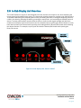
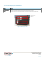
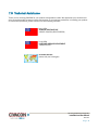
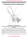
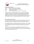
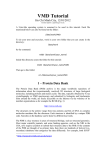
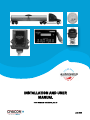
Table of Contents
INSTALLATION AND USER
MANUAL
PART NUMBER H53162PA, Rev. 6
June 2014
This page intentionally left blank for printed publication.
ii
Table of Contents
Dear Customer:
We‟ve developed this manual to help you with your everyday AutoTemp needs. We hope you‟ll find this guide
both helpful and easy to use.
We‟d like to point out some things to keep in mind when using this resource online:
First, make sure you have the latest version of Adobe Acrobat Reader so you can quickly access the section of
the manual you need. (Earlier versions of Adobe won‟t allow you to use all the features we‟ve built into this
document.) Go to http://get.adobe.com/reader/ to download the free app or update your current version of
Adobe.
To navigate through this document, simply go to the Table of Contents page and click on any item you want to
read about. You‟ll be immediately redirected to that portion of the manual. Anywhere a figure is mentioned (the
text will have a box around it), you can click on the box and be immediately redirected to that specific figure.
We appreciate any feedback you can provide to make this manual better for the user. Whether we didn‟t
make something as clear as we thought, or even if something is misspelled, please let us know so we can
continuously improve the quality of this manual. Naturally, we would also like to hear from you on the things
you like! Please address your comments to our technical support team.
This document and all the information herein is the property of CIVACON.
It is proprietary and shall not be copied, and is not to be used directly or indirectly
in any way detrimental to the interest of CIVACON.
All copyright and intellectual property rights are reserved.
© 2011
4304 N. Mattox Rd.
Kansas City, MO 64150
This page intentionally left blank for printed publication.
ii
Table of Contents
1.0
AutoTemp System Product Description ....................................................................................................................... 1
2.0
In-Cab Display Unit Overview ..................................................................................................................................... 2
2.1
In-Cab Display Unit Installation .......................................................................................................................................3
2.2 In-Cab Display Unit Button Functions ..............................................................................................................................4
2.2.1
Pre-Heat Button .....................................................................................................................................................4
2.2.2
Limits Button ..........................................................................................................................................................5
2.2.3
New Load Button ...................................................................................................................................................5
2.2.4
Setup Button ..........................................................................................................................................................5
2.2.4.1
Setup Menu Options ....................................................................................................................................6
2.2.5
OK Arrow ................................................................................................................................................................7
2.2.6
Up and Down Arrows .............................................................................................................................................8
2.2.7
Print Arrow .............................................................................................................................................................8
2.2.8
End Load Button.....................................................................................................................................................9
2.2.9
Link Button .............................................................................................................................................................9
2.2.10 Snooze Button ......................................................................................................................................................10
2.3
Messages .......................................................................................................................................................................11
2.4
Log Output .....................................................................................................................................................................12
2.5 Log Format ....................................................................................................................................................................13
2.5.1
Alarm/Temperature Records Format ..................................................................................................................15
2.5.2
Action Records Format ........................................................................................................................................15
2.5.3
Status Records Format .........................................................................................................................................16
3.0
Temperature Monitoring Unit Overview ....................................................................................................................17
3.1
Temperature Monitoring Unit Installation ....................................................................................................................18
3.2
Temperature Monitoring Unit Display ...........................................................................................................................19
3.3 Temperature Monitoring Unit Button Functions ...........................................................................................................19
3.3.1
Linking with In-Cab Display Unit ..........................................................................................................................19
3.3.2
Linking with Ball Valve .........................................................................................................................................20
3.3.3
Resetting ..............................................................................................................................................................20
3.3.4
Send Current Temperature ..................................................................................................................................20
3.4
Temperature Monitoring Unit Normal Operation .........................................................................................................21
3.5
Temperature Monitoring Unit/In-Cab Display Unit Link Operation ..............................................................................21
3.6
Temperature Monitoring Unit Battery ..........................................................................................................................22
3.7 Internal Jumpers and Switch..........................................................................................................................................22
3.7.1
Valve Disable Jumper(s) (V/J4) .............................................................................................................................22
3.7.2
Switch ...................................................................................................................................................................23
3.7.3
Thermocouple (T/J8) ............................................................................................................................................24
4.0
Wireless Valve Controller and Ball Valve Overviews ...................................................................................................26
4.1
Wireless Valve Controller / Ball Valve Installation ........................................................................................................27
4.2 Wireless Valve Controller Lights ....................................................................................................................................28
4.2.1
Normal Operation Lights ......................................................................................................................................28
i
4.2.2
4.2.3
Link Mode Lights ..................................................................................................................................................28
Erasing the Wireless Valve Controller ..................................................................................................................28
4.3 Temperature Control Algorithm Conditions ..................................................................................................................29
4.3.1
Normal Operation Temperature ..........................................................................................................................29
4.3.2
Pre-Heat Operation Temperature ........................................................................................................................29
4.4
Wireless Valve Controller Linking Process .....................................................................................................................30
5.0
Quick Reference Instructions ......................................................................................................................................31
6.0
Warranty ....................................................................................................................................................................33
7.0
Technical Assistance ...................................................................................................................................................34
List of Figures
Figure 1. AutoTemp System Components ............................................................................................................................. 1
Figure 2. In-Cab Display Unit, Part No. 3601T ....................................................................................................................... 2
Figure 3. Mounting the Unit ................................................................................................................................................. 3
Figure 4. Printer Connected to In-Cab Display Unit ..............................................................................................................12
Figure 5. Printer Connected to Cable for Computer Use ......................................................................................................12
Figure 6. Log Printout Example, Start ...................................................................................................................................13
Figure 7. Log Printout Example, End ....................................................................................................................................14
Figure 8. Temperature Monitoring Unit, Part No. 3602T ......................................................................................................17
Figure 9. Solid-State Temperature Sensor, With and Without K-Type Thermocouple ..........................................................17
Figure 10. Temperature Monitoring Unit Mounting Locations .............................................................................................18
Figure 11. Valve Disable Jumper Placement (J4) ..................................................................................................................22
Figure 12. Switch .................................................................................................................................................................23
Figure 13. Two-Pin Head for Shorting Jumper Placement (J8) to Enable Thermocouple.......................................................24
Figure 14. Connection for Thermocouple .............................................................................................................................25
Figure 15. Electronic Wireless Valve Controller, Part No. 3603T..........................................................................................26
Figure 16. Electronically Actuated Ball Valve, Part No. 3604T .............................................................................................26
Figure 17. Components Joined with Three-Pin Connector.................................................................................................... 26
Figure 18. Mounted Wireless Valve Controller and Ball Valve ...........................................................................................27
ii
1.0 AutoTemp System Product Description
This manual describes the system operation and wireless linking process for AutoTemp, a patent-pending
temperature control system for tank trucks or trailers. The AutoTemp system can be used solely as a
temperature-monitoring system or as a temperature-monitoring and closed-loop control system. The
AutoTemp system allows drivers to easily monitor product temperature from an In-Cab Display Unit while
driving, eliminating the time-consuming “stop-and-check” process with traditional temperature gauges.
The AutoTemp system (Figure 1) uses a solid-state digital temperature sensor to monitor tank shell
temperature and wirelessly transmit the reading to an in-cab receiver every 15 minutes. The In-Cab Display
Unit (receiver) is used to set the system temperature control settings and provides an interface with the tank
truck operator. The system can also alert the driver the second a temperature issue occurs.
The Temperature Monitoring Unit communicates with the Wireless Valve Controller to open and close the
flow through the electronically actuated ball valve and maintain coolant temperature within set limits. The
client is assured of product integrity through constant monitoring, while the company owner is safeguarded
against potentially expensive temperature control issues.
The AutoTemp system logs each time-stamped temperature reading and can produce detailed reports in
seconds, either with the addition of a hand-held thermal printer that can be used on the spot, or by
connecting the display unit to a printer. Either way, both the driver and customer can have an accurate,
in-transit report for their records.
Temperature
Monitoring Unit
In-Cab
Display Unit
Wireless Valve
Controller
Ball Valve
Figure 1. AutoTemp System Components
AutoTemp Temperature Control System
Installation and User Manual
June 2014
Page 1
2.0 In-Cab Display Unit Overview
The In-Cab Display Unit (Figure 2) was designed to be both intuitive and simple to use, while displaying the
current activity and settings of the system. The face panel includes buttons for creating a link (pairing) with a
Temperature Monitoring Unit, adjusting alarm limits, pre-heating the trailer, marking the beginning or end of
a load in the data log, dumping the data log, entering the setup menu, and controlling the audible portion of
alarms. The face panel buttons can also allow the driver to view the radio signal strength and adjust the
contrast of the display. Upper level functions can be accessed simply by pushing the desired button or arrow;
lower level functions can be accessed by pushing and holding down the Snooze/Shift button while selecting
the desired function. For example, to print, push and hold the Snooze/Shift button while pushing the
Down/Print arrow.
Information
Display Area
Alarm Light
12V Power
Plug-In
Control Buttons
Figure 2. In-Cab Display Unit, Part No. 3601T
AutoTemp Temperature Control System
Installation and User Manual
June 2014
Page 2
2.1 In-Cab Display Unit Installation
Step
In-Cab Display
Unit
Action
Apply the provided Velcro® strips to the unit and press into place.
Attach the unit in a convenient location in the cab for easy access by the driver.
Suggested Velcro
placement
Figure 3. Mounting the Unit
AutoTemp Temperature Control System
Installation and User Manual
June 2014
Page 3
2.2 In-Cab Display Unit Button Functions
2.2.1 Pre-Heat Button
To select between pre-heat on/off, temperature adjustments, and normal operation:
Step
Action
Display current
Pre-Heat state /
temperature setting
Press and release the PRE-HEAT/LIMITS button.
° PRE-HEAT displays, along with the current Pre-Heat state (OFF or END).
° If the current temperature is at or above the Pre-Heat set point, END will
be displayed and the Pre-Heat End Alarm will sound.
° If the current temperature is not at or above the Pre-Heat set point, OFF
will be displayed.
If temperature
displayed IS correct
and Pre-Heat is OFF
Press and release the UP/OK or DOWN/PRINT arrows to turn on Pre-Heat mode.
° If the current temperature is at or above the Pre-Heat set point, Pre-Heat
cannot be turned on.
If temperature
displayed IS NOT
correct
Press and release the PRE-HEAT/LIMITS button again to select the Pre-Heat
temperature setting.
Press the UP/OK or DOWN/PRINT arrows to adjust the Pre-Heat temperature
setting.
Return to Pre-Heat
ON/OFF
Press and release the PRE-HEAT/LIMITS button twice more.
Press and release the PRE-HEAT/LIMITS button one more time to select the
Pre-Heat temperature setting while Pre-Heat is ON.
Adjust the temperature setting using the UP/OK or DOWN/PRINT arrows while
Pre-Heat is ON.
Exit Pre-Heat
Press and release the PRE-HEAT/LIMITS button again to exit and shut OFF PreHeat function.
Note(s)
When Pre-Heat mode is ON, the Ball Valve will open.
Once the desired temperature is reached, END will be displayed, the Pre-Heat
End Alarm will sound, and the Ball Valve will close.
Pre-Heat temperature may be adjusted while END is displayed, but the
adjustment will not take effect until the next Pre-Heat cycle.
When Pre-Heat is in the ON or END condition, normal temperature regulation will
not occur.
When Pre-Heat is OFF and there is no activity for 30 seconds, the In-Cab Display
Unit will return to normal operation, including temperature regulation.
AutoTemp Temperature Control System
Installation and User Manual
June 2014
Page 4
2.2.2 Limits Button
To select between the high/low alarm limits and normal operation:
Step
Action
Activate limits
Press and hold down the SNOOZE/SHIFT button while pressing the PRE-HEAT/LIMITS
button.
Push the UP/OK or DOWN/PRINT arrows to adjust settings.
Cycle through
limits
Press and hold down the SNOOZE/SHIFT button while pressing the PRE-HEAT/LIMITS
button once for each selection.
° When high or low limits are selected, a „>‟ will appear next to the selection.
° The „>‟ will flash if there is an alarm affected by the selected limit.
° If no adjustment is made for 30 seconds, the selection will revert to normal
operation.
2.2.3 New Load Button
To mark the log memory and define one end of the log data for printing:
Step
Place New
Load mark
Action
Press the NEW LOAD/SETUP button twice.
° A beep will sound and a New Load mark will be placed in the log memory.
° See Section 2.2.8 for End of Load instructions.
2.2.4 Setup Button
To select the Setup menu:
Step
Select Setup
menu
Action
Press and hold down the SNOOZE/SHIFT button while pressing the NEW
LOAD/SETUP button.
° Each press of the button advances to the next menu item and stores the value of
the current menu item.
° After all menu items have been shown, the control returns to normal operation.
AutoTemp Temperature Control System
Installation and User Manual
June 2014
Page 5
2.2.4.1 Setup Menu Options
Option
Action
Brightness
Use the UP/OK or DOWN/PRINT arrows to adjust display brightness from 0 (Off) to
9 (Full).
Auto-Print
Use the UP/OK or DOWN/PRINT arrows to select auto-print on or off.
° When auto-print is on, the most recent log will automatically print when the END
LOAD/LINK button is pressed.
Display
C° / F°
Use the UP/OK or DOWN/PRINT arrows to select the temperature units used for
display and log printing.
Select “F” for Fahrenheit or “C” for Centigrade .
Time Zone
Use the UP/OK and DOWN/PRINT arrows to increase or decrease the time zone
offset from GMT.
° The allowed range is +/- 12 hours in one-hour increments.
° Once the time zone offsets, the readings in the log will all be shifted to the new time
zone.
° Original factory setting is GMT – 6, Central Standard Time.
TIME ZONE
EST
CST
MST
PST
EDT
CDT
MDT
PDT
GMT OFFSET
GMT - 5
GMT - 6
GMT - 7
GMT - 8
GMT – 4
GMT – 5
GMT – 6
GMT - 7
NOTE: System DOES NOT automatically adjust for Daylight Savings Time.
Time Set
Use the UP/OK and DOWN/PRINT arrows to increase or decrease the clock time by
minutes.
° Time adjustment is limited to +/- 20 minutes around the original factory setting.
° The In-Cab Display Unit uses a high-stability, temperature-compensated clock that
drifts a maximum of +/- 2 minutes per year over the full temperature range of
-40° F to +185° F (-40°C to +85°C).
° The adjustment range can compensate for up to 10 years of clock drift.
AutoTemp Temperature Control System
Installation and User Manual
June 2014
Page 6
Option
Action
Print Old Log
Press the UP/OK and DOWN/PRINT arrows to select a log segment.
° A count of log segments is displayed (0 = Current), along with a segment mark
code.
° Log segments are separated by log marks:
Mark
E
N
B
What it means
End Load
New Load
Basic Record
END
End of Log
What it does
Marks the end of a load.
Starts a new load record.
Occurs when the first or last record in
memory is not a mark.
Last segment in memory.
° END is displayed for the last segment of log memory.
° Time displayed reflects the time the mark or record was logged.
2.2.5 OK Arrow
The UP/OK arrow will allow you to exit from the Setup menu and resume normal operation.
Step
Exit Setup
menu
Action
Press and hold down the SNOOZE/SHIFT button while pressing the UP/OK arrow.
° This action will store the current menu item value.
AutoTemp Temperature Control System
Installation and User Manual
June 2014
Page 7
2.2.6 Up and Down Arrows
Step
Adjust
selected item
Action
Press the UP/OK or DOWN/PRINT arrows to adjust the selected item.
° The value increases or decreases once for each button press.
° If an Up or Down arrow is held for one second, the function will auto repeat at a rate
of three steps per second.
° If a limit or preheat setting is changed and no further adjustment occurs for two
seconds, the current setting will be stored in memory.
Note (s)
If both the UP/OK and DOWN/PRINT arrows are pressed at the same time, the sent
and received signal strength for the last exchange will be displayed in the High and
Low limit positions. Displayed as negative numbers, -40 is stronger than -60. The
device type that sent the message is shown in the temperature position: 3 =
Temperature Monitoring Unit, 2 = Ball Valve.
If no specific item is selected, the UP/OK and DOWN/PRINT arrows can adjust the
contrast of the display. (The changes are subtle, so it may take a few tries to get the
contrast you want.)
2.2.7 Print Arrow
To send log data to the printer:
Step
Action
Print log
Press and hold down the SNOOZE/SHIFT button while pressing the DOWN/PRINT
arrow.
° Log data will be sent to the printer port.
° The control will scan the log memory for an End Load (E) / New Load (N) mark pair
and print the data between the two marks.
Note(s)
If a New Load (N) mark is found before an End Load (E) mark, it is assumed there is a
current load and the data from the present time to the New Load (N) mark is printed.
If two End Load (E) marks are found with a New Load (N) mark, it is assumed the
New Load button was not used and the data between the two End Load (E) marks is
printed.
Normal use assumption is that log data between New Load and End Load will be printed while a load is in
the trailer. Log data is also stored while the trailer is empty. Any portion of the log data may be accessed with
the Print Old function in the Setup menu. (See Section 2.4, Log Output, for details on connection and log
format.)
AutoTemp Temperature Control System
Installation and User Manual
June 2014
Page 8
2.2.8 End Load Button
To define one end of the log memory for printing:
Step
Mark End
Load for
printing
Action
Press the END LOAD/LINK button twice.
° The control will beep and place an End Load (E) mark on the log memory.
° The mark defines the end of the log for printing. (See Section 2.5, Log Format, for
images.)
2.2.9 Link Button
To link the In-Cab Display Unit to the Temperature Monitoring Unit:
Step
Action
Start linking
process
Press and hold down the SNOOZE/SHIFT button while pressing the END LOAD/LINK
button.
° The In-Cab Display Unit will display “LINKING.”
° The In-Cab Display Unit will next scan available frequencies for the one with the
least interference on it and randomly pick a channel to form a link association.
If In-Cab
Display Unit
detects
another unit
also in linking
process
In-Cab Display Unit will stop its link process and display the message, “LINK FAILED.”
Press and hold down the SNOOZE/SHIFT button while pressing the END LOAD/LINK
button again to try another channel for the unit.
° If the selected channel is busy, give the other In-Cab Display Unit time to finish its
linking process and try to link again.
° “Link Failed” will also be displayed if the link process is not completed within five
minutes of initiating the linking process. The In-Cab Display Unit will then revert to
its previous settings.
When linking
process is
complete
Abort linking
process
In-Cab Display Unit will display the ID number of the Temperature Monitoring Unit.
° The unit memorizes the ID number, frequency, and channel.
Manually verify this ID number with the ID label on the Temperature Monitoring Unit.
Remove power from the In-Cab Display Unit by unplugging the unit from the 12V
power port.
° The In-Cab Display Unit will revert to its previous settings when it is powered on.
AutoTemp Temperature Control System
Installation and User Manual
June 2014
Page 9
2.2.10 Snooze Button
The snooze feature allows the driver to silence an alarm when needed.
Step
Silence
audible alarm
Extend snooze
and silent
modes
Action
Press and release the SNOOZE/SHIFT button.
° The In-Cab Display Unit will go silent and snooze for 30 minutes.
° The alarm light will continue to flash.
Press and release the SNOOZE/SHIFT button again.
° The snooze period will be extended for an additional 30 minutes.
° The alarm light will continue to flash.
Indefinitely
silence
audible alarm
Press and hold the SNOOZE/SHIFT button for 15 seconds.
° The alarm light will continue to flash.
Reactivate
audible alarm
Press the SNOOZE/SHIFT button once to cancel silent mode.
° The audible alarm will immediately sound.
Note(s)
The snooze feature only works when there is an active alarm.
Any change in alarm condition will cancel Snooze or Silent modes, e.g., when the
temperature comes back into limit or when a new alarm is created, such as when the
In-Cab Display Unit loses communication with the Temperature Monitoring Unit.
AutoTemp Temperature Control System
Installation and User Manual
June 2014
P a g e 10
2.3 Messages
Messages are projected in the information display area. Multiple messages may be displayed by rotating
each message for one second.
Message
What it shows
ID XXXX
The ID number of the last Temperature Monitoring Unit that formed a linkage association
with the In-Cab Display Unit.
ID Lost
There has been no communication with the Temperature Monitoring Unit for over 30
minutes1 and the link is lost2.
(Link Lost)
Linking
Link button has been pressed and the In-Cab Display Unit is searching for a Temperature
Monitoring Unit in link mode.
Low Battery
The battery in the associated Temperature Monitoring Unit is low and should be replaced
soon.
Link Failed
Another nearby In-Cab Display Unit is in link mode or already using the same frequency
and channel3, five minutes have elapsed without establishing a link action, or Bluetooth
and Wi-Fi equipment are nearby4.
Valve Lost
The In-Cab Display Unit has received no messages from the Ball Valve for over 30
minutes5.
Note(s)
1 Alarm
condition. If the In-Cab Display Unit has just been powered on, it will wait for 20
minutes before activating an alarm to allow the Temperature Monitoring Unit time to send a
message.
2 Briefly press the green button on the face of the Temperature Monitoring Unit to force a
radio transmission to restore the link.
3 Bluetooth and Wi-Fi could interfere during the linking process if they are less than three
feet way; there are no issues with either of these at any time except during linking.
4 Wait about 10 seconds and then attempt to link again by pressing and holding down the
SNOOZE/SHIFT button while pressing the END LOAD/LINK button.
5 Ball Valve typically transmits once per minute.
Several things can cause a Link Lost condition:
1) The Temperature Monitoring Unit is out of range (beyond approximately 80 feet).
2) Something is blocking the signal, e.g., the In-Cab Display Unit and trailer are at extreme angles to each
other; something has been placed on either unit that blocks the signal; or portions of a loading rack are
nearby.)
3) Interference from Bluetooth or Wi-Fi, both of which use the same frequency band and transmit at much
higher powers. These signals can completely swamp a receiver with too much power, regardless of the
frequency in use. Try repeating the link process so the In-Cab Display Unit will choose a frequency not
currently in use.
AutoTemp Temperature Control System
Installation and User Manual
June 2014
P a g e 11
2.4 Log Output
The log can be printed using the DB9 serial connector on the side of the In-Cab Display Unit (Figure 4). The
connector is configured to drive a serial, hand-held thermal printer (CIVACON Part #3605T).
The log can also be printed directly to a computer by using a “null” modem in-cable (Pins 2 and 3 crossed)
(Figure 5). The serial port is configured at 38400 baud, 8 data bits, no parity, and 1 stop bit (38400, 8N1).
Pin 5 is ground. Pin 3 is transmit data and uses RS-232 signal levels that are pre-set from the factory.
DB9 Serial
Connector
Figure 4. Printer Connected to In-Cab Display Unit
“Null” Modem
In-Cable
Figure 5. Printer Connected to Cable for Computer Use
AutoTemp Temperature Control System
Installation and User Manual
June 2014
P a g e 12
2.5 Log Format
The log begins with a start time mark and the most recent trailer ID, followed by column headings. The next
entries are the four data records: (1) action, (2) ID, (3) alarm, and (4) status.
Every record has a time and date stamp (see Figure 6). Time is in hours : minutes in 24-hour format and
noted time zone. The date is in a mm/dd/yy format. The end of the log (Figure 7) is also indicated in the
printout.
The temperature units (C° or F°) are shown in the TMP column.
Action
Temperature
Transmitter ID
Alarm
Figure 6. Log Printout Example, Start
AutoTemp Temperature Control System
Installation and User Manual
June 2014
P a g e 13
Status
Figure 7. Log Printout Example, End
AutoTemp Temperature Control System
Installation and User Manual
June 2014
P a g e 14
2.5.1 Alarm/Temperature Records Format
Active alarms can mean a number of things:
Alarm
What it means
L
Temperature below low limit.
H
Temperature above high limit.
B
Low battery, Temperature Monitoring Unit.
Z
Audible alarm in snooze mode.
S
Audible alarm silenced.
2.5.2 Action Records Format
Item
Format
Line 1
Status, time, and date.
Line 2
ID; identifies the trailer used when status was reported.
Line 3
Alarm, high/low temperatures, time, and date.
Reported
Action
What it means
End Load
Indicates the end of a load. Trailer ID is also reported.
New Load
Indicates the beginning of a load. Trailer ID is also reported.
Power On
In-Cab Display Unit turned on.
Clock Adj
User adjusted clock setting. Time and date reflect the update.
AutoTemp Temperature Control System
Installation and User Manual
June 2014
P a g e 15
2.5.3 Status Records Format
Item
Format
Line 1
Status, time, and date.
Line 2
Temperature, time, and date.
Line 3
End record status.
Reported
Status
What it means
Linked
A new link between In-Cab Display Unit and Temperature Monitoring Unit created.
Sender Lost
No communication received from Temperature Monitoring Unit for over 30 minutes.
Valve Lost
No communication received from Ball Valve for over 30 minutes.
AutoTemp Temperature Control System
Installation and User Manual
June 2014
P a g e 16
3.0 Temperature Monitoring Unit Overview
The Temperature Monitoring Unit (Figure 8) is attached to the tank shell and sends a temperature reading
to the In-Cab Display Unit every 15 minutes. The unit takes a temperature reading by means of either a
solid-state temperature sensor soldered into the unit (normal use), or a K-type thermocouple (Figure 9)
connected to the unit and inserted into a thermal well or placed at the bottom of the tank shell (high-heat or
rugged conditions). The Temperature Monitoring Unit spends most of its time asleep to conserve battery life,
waking only very briefly to take a reading.
Temperature
Readout
Function Selection
Button
Figure 8. Temperature Monitoring Unit, Part No. 3602T
K-Type Thermocouple
Solid-State Sensor
Figure 9. Solid-State Temperature Sensor, With and Without K-Type Thermocouple
AutoTemp Temperature Control System
Installation and User Manual
June 2014
P a g e 17
3.1 Temperature Monitoring Unit Installation
Step
Temperature
Monitoring Unit
(with Solid-State
Temperature Sensor
or K-Type
Thermocouple)
Action
Use screws to securely mount the Temperature Monitoring Unit in place. (Mounting
holes are pre-drilled; see Figure 10.)
° The Solid-State Temperature Sensor is installed in the unit (standard use).
If used, place the K-Type Thermocouple into a thermal well or at the bottom of the
tank shell (high-heat or rugged use).
° Apply enough epoxy to fully coat the back side of the thermocouple to keep it in
place (see Figure 10).
° Follow manufacturer‟s instructions for mixing and using the epoxy.
Mounting hole
Suggested epoxy
placement
Figure 10. Temperature Monitoring Unit Mounting Locations
AutoTemp Temperature Control System
Installation and User Manual
June 2014
P a g e 18
3.2 Temperature Monitoring Unit Display
The Temperature Monitoring Unit Display projects the current temperature in degrees Fahrenheit (letter “F”)
or degrees Centigrade (letter “C”); it may also display an “L” when the link process is active or when resetting
is required. The display remains off between readings to conserve battery power.
When a battery is installed or the Temperature Monitoring Unit is reset, the display will perform a display test
sequence, illuminating each display bar light one at a time. The test sequence is followed by the first three
digits of the In-Cab Monitoring Unit identification number (ID), then the last three digits of the six-digit ID
number. If the test sequence stalls for an extended time, check to see if the temperature-sensing element is
disconnected or defective; in these instances, the display will read “ERR.”
3.3 Temperature Monitoring Unit Button Functions
The Temperature Monitoring Unit has a single green button on its face that performs three functions:
(1) links between the In-Cab Display Unit and the Temperature Monitoring Unit; (2) pairs with the Wireless
Valve Controller during installation; and (3) resets the Temperature Monitoring Unit. The green button must
be held for at least one tenth of a second to be considered a valid button press and send new information.
3.3.1 Linking with In-Cab Display Unit
Linking with an In-Cab Display Unit is essential for the AutoTemp Temperature Control System to function
properly.
Step
Link
Temperature
Monitoring Unit
with
In-Cab Display
Unit
Action
Press and hold down the SNOOZE/SHIFT button while pressing the
END LOAD/LINK button.
Press and hold down the green button on the face of the Temperature Monitoring
Unit until an “L” is displayed, usually within 10 seconds.
Release green button to start the linking process.
AutoTemp Temperature Control System
Installation and User Manual
June 2014
P a g e 19
3.3.2 Linking with Ball Valve
If an optional Wireless Valve Controller is used, it is essential to link it to other components during
installation for proper operation of the AutoTemp Temperature Control System.
Step
Action
Link
Temperature
Monitoring Unit
with Wireless
Valve Controller
Press and hold down the SNOOZE/SHIFT button while pressing the
END LOAD/LINK button.
Press and hold down the green button on the face of the Temperature Monitoring
Unit until an “L” is displayed, usually within 10 seconds.
Release green button to start the linking process.
3.3.3 Resetting
The Temperature Monitoring Unit may need to be reset if the identification sticker on the Temperature
Monitoring Unit is missing or is illegible, as the Temperature Monitoring Unit will only operate with the In-Cab
Display Unit it was originally linked to. Resetting may also be necessary if the unit becomes stuck or
otherwise ceases to operate properly. While both of these scenarios are rare, there is a simple solution that
can be used if needed:
Step
Reset the
Temperature
Monitoring Unit
Note(s)
Action
Press and hold down the green button on the face of the unit for 10 seconds.
The battery can also be removed and re-installed to reset the Temperature Monitoring
Unit, although this is usually not necessary.
3.3.4 Send Current Temperature
To send the current temperature to the In-Cab Display Unit:
Step
Access current
temperature
Note(s)
Action
Press and release the green button on the face of the Temperature Monitoring Unit.
If the green button on the Temperature Monitoring Unit is pressed and released in
less than two seconds, the unit will display the current temperature and attempt to
send it to the associated In-Cab Display Unit. This function is useful for quickly clearing
a “Link Lost” condition in the In-Cab Display Unit (see Section 2.0, In-Cab Display Unit
Overview).
AutoTemp Temperature Control System
Installation and User Manual
June 2014
P a g e 20
3.4 Temperature Monitoring Unit Normal Operation
In normal operation, the Temperature Monitoring Unit wakes every 15 minutes to take a temperature
reading and battery voltage measurement; it then attempts to send the results to the associated In-Cab
Display Unit. When the In-Cab Display Unit acknowledges the transmission or the Temperature Monitoring
Unit times out because of a non-responsive In-Cab Display Unit, the Temperature Monitoring Unit will go back
to sleep. The Temperature Monitoring Unit is typically awake for less than one-half second per reading.
If the In-Cab Display Unit does not immediately acknowledge the transmission, the Temperature Monitoring
Unit will attempt repeated transmissions of approximately one second each, for up to 50 attempts. The Unit
will then go into a scanning mode for approximately four seconds as it continues to search for the associated
In-Cab Display Unit. If the Temperature Monitoring Unit fails to find the In-Cab Display Unit, it goes back to
sleep.
3.5 Temperature Monitoring Unit/In-Cab Display Unit Link Operation
A linking association (pairing) must be formed between a Temperature Monitoring Unit and an In-Cab
Display Unit to ensure the In-Cab Display Unit only displays data from the correct Temperature Monitoring
Unit. To accomplish this pairing, a specific radio channel is randomly assigned to the unit.
Step
Action
Create a
linking
association
Press and hold down the green button on the face of the Temperature Monitoring Unit
until an “L” is displayed, usually within 10 seconds.
° The linking association will begin once the button is released.
° The Temperature Monitoring Unit will scan for an In-Cab Display Unit in Link mode for
up to two minutes.
° The first temperature and battery measurements will be sent to the In-Cab Display Unit
immediately after the link process is complete, and the Temperature Monitoring Unit
will return to normal operation.
° When the In-Cab Display Unit is found, the “L” will blink and a series of numbers will be
displayed as the phases of the link process progress.
° If the link process does not complete within two minutes, the Temperature Monitoring
Unit will revert to normal operation under its previous pairing and the “L” will go out.
Note(s)
Once a Temperature Monitoring Unit has been linked to a Ball Valve, it must always be
used with a Ball Valve (although not necessarily the one it was linked to originally) unless
it is changed back to the “No Valve” condition using the internal Valve Disable Jumper
(see Section 3.7.1).
If a Ball Valve is used on the trailer, the Temperature Monitoring Unit must be linked
(paired) with it. This pairing is typically done at installation.
If the green button on the face of the Temperature Monitoring Unit is pressed and
released in less than two seconds, the Unit will display the current temperature and
attempt to send it to the associated In-Cab Display Unit. This function is useful for quickly
clearing a “Link Lost” condition in the In-Cab Display Unit (see Section 2.0, In-Cab
Display Unit Overview).
AutoTemp Temperature Control System
Installation and User Manual
June 2014
P a g e 21
3.6 Temperature Monitoring Unit Battery
The battery operating the Temperature Monitoring Unit is a 3.6V extended temperature-range lithium cell
that is only available from the CIVACON (generic Type II). Battery life typically exceeds five years.
3.7 Internal Jumpers and Switch
The Temperature Monitoring Unit contains three internal configuration controls, along with two jumpers and
a switch.
3.7.1 Valve Disable Jumper(s) (V/J4)
As the name implies, Valve Disable Jumpers (Figure 11) prevent the Temperature Monitoring Unit from
forming a valve link.
Step
Action
Erase Valve
Link
Place a Valve Disable Jumper on this two-pin header.
Reset the
Temperature
Monitoring Unit
Press and hold the green button on the face of the unit for 10 seconds.
Note(s)
To enable Control Valve links, remove the jumper and reset the Temperature
Monitoring Unit (Step 2 above).
Figure 11. Valve Disable Jumper Placement (J4)
AutoTemp Temperature Control System
Installation and User Manual
June 2014
P a g e 22
3.7.2 Switch
The switch (Figure 12) allows the user to select the display units on the Temperature Monitoring Unit.
Step
Flip switch
Action
Choose “F” for degrees Fahrenheit.
Choose “C” for degrees Centigrade.
The switch setting will take effect the next time a temperature is displayed.
Figure 12. Switch
AutoTemp Temperature Control System
Installation and User Manual
June 2014
P a g e 23
3.7.3 Thermocouple (T/J8)
The Temperature Monitoring Unit comes with a solid-state temperature sensor for standard use. However,
the Unit can optionally use a K-type thermocouple to take temperature readings for special applications,
such as high temperatures or rugged duty.
Step
Action
Enable
thermocouple
Place a shorting jumper on this two-pin header (Figure 13).
° This action will disable the solid-state temperature sensor the next time the
Temperature Monitoring Unit resets.
Reset the
Temperature
Monitoring Unit
Press and hold the green button on the face of the unit for 10 seconds.
Enable
Solid-State
Temperature
Sensor
Remove the jumper and reset the Temperature Monitoring Unit (Step 2 above).
Figure 13. Two-Pin Head for Shorting Jumper Placement (J8) to Enable Thermocouple
AutoTemp Temperature Control System
Installation and User Manual
June 2014
P a g e 24
Figure 14. Connection for Thermocouple
AutoTemp Temperature Control System
Installation and User Manual
June 2014
P a g e 25
4.0 Wireless Valve Controller and Ball Valve Overviews
The optional Wireless Valve Controller and Ball Valve (Figure 15 and Figure 16) work in conjunction with one
another and with both the Temperature Monitoring Unit and the In-Cab Display Unit. When present, the
Wireless Valve Controller opens and closes the Ball Valve in the trailer‟s heat exchange inlet line to regulate
the flow of coolant to the trailer.
The Wireless Valve Controller is in the “erased” condition when shipped from the factory and automatically
starts a “Link” (pairing) operation when powered. The Wireless Valve Controller may take up to two minutes
to actuate the Ball Valve in response to a change in conditions. The two units are connected with a three-pin
connector (Figure 17).
Figure 15. Electronic Wireless Valve Controller,
Part No. 3603T
Figure 16. Electronically Actuated Ball Valve,
Part No. 3604T
Figure 17. Components Joined with Three-Pin Connector
AutoTemp Temperature Control System
Installation and User Manual
June 2014
P a g e 26
4.1 Wireless Valve Controller / Ball Valve Installation
Step
Action
Wireless Valve
Controller
Use two long screws to mount the Wireless Valve Controller to the trailer or truck
through the pre-drilled holes.
Ball Valve
Properly support the Ball Valve with a bracket or other mounting hardware.
Figure 18. Mounted Wireless Valve Controller and Ball Valve
AutoTemp Temperature Control System
Installation and User Manual
June 2014
P a g e 27
4.2 Wireless Valve Controller Lights
The Wireless Valve Controller comes equipped with red and green lights. In all modes, the red light will slowly
blink for a few seconds at power on to indicate the Wireless Valve Controller is initializing. The red light
blinks off briefly while the controller is searching for an In-Cab Display Unit. The red light becomes steady
when the Ball Valve is ready.
4.2.1 Normal Operation Lights
During normal operation, the red and green lights provide Wireless Valve Controller status:
Light
Function
Red light
Stable to indicate unit is on.
Green light
On when the Ball Valve is open.
Off when the Ball Valve is closed.
4.2.2 Link Mode Lights
Light
Function
Red light
Alternates blink with green light when trying to link.
Red light turns off when link is successful.
Green light
On to indicate a successful link.
4.2.3 Erasing the Wireless Valve Controller
Step
Erase
Wireless Valve
Controller
Action
Power on the Wireless Valve Controller and wait a few seconds until the red light
becomes steady.
Place a strong magnet on the face of the Wireless Valve Controller just to the left of
the connector until the green light starts to flash (about two seconds).
Remove the strong magnet until both the red and green lights blink in unison (about
two seconds).
Place a strong magnet back on the face of the Wireless Valve Controller, just to the
left of the connector, until the red and green light start to flash in alternation (about
two seconds).
° The Wireless Valve Controller in now erased.
To abort the erase process, remove power from the Wireless Valve Controller.
AutoTemp Temperature Control System
Installation and User Manual
June 2014
P a g e 28
4.3 Temperature Control Algorithm Conditions
4.3.1 Normal Operation Temperature
Condition
Result
Temperature
limits set at
least 15° F
apart
Ball Valve opens when the temperature is less than 5° above the lower limit.
Ball Valve closes when the temperature is greater than 5° below the upper limit.
Temperature
limits set less
than 15° F
apart
Temperature range splits into thirds.
Ball Valve opens if temperature is at or below lowest one-third.
Ball Valve closes if temperature is at or above highest one-third.
4.3.2 Pre-Heat Operation Temperature
Condition
Result
Ball Valve
open
In-Cab Display Unit is in Pre-Heat Mode.
Pre-Heat is ON.
Temperature is below Pre-Heat set point.
Ball Valve
closed
Pre-Heat set point is reached.
AutoTemp Temperature Control System
Installation and User Manual
June 2014
P a g e 29
4.4 Wireless Valve Controller Linking Process
During the linking process, the Wireless Valve Controller and Temperature Monitoring Unit memorize each
other‟s internal ID numbers. The Wireless Valve Controller will only accept temperature readings,
temperature limits, and commands that have been tagged with the Temperature Monitoring Unit‟s internal
ID number. The Temperature Monitoring Unit then passes the associated Wireless Valve Controller internal
ID number to the In-Cab Display Unit during the linking process. Each component works in-sync with the
other to form a cohesive, fully functioning system.
Step
Action
Create a
linking
association
Make sure there are no other Wireless Valve Controllers or In-Cab Display Units
operating in the vicinity.
o These can interfere and cause the linking process to fail.
Power on an erased Wireless Valve Controller.
After approximately five seconds, the red and green lights will blink back and forth
to indicate the Wireless Valve Controller is erased and has entered Link mode.
Link with the
Temperature
Monitoring Unit
Ensure the Wireless Valve Controller is in Link mode.
° Press and hold down the green button on the Temperature Monitoring Unit until
an “L” appears on the display.
° This will activate the “Link” (pair) mode.
° The “L” will blink several times as the linking process progresses.
° If the linking process is successful, the “L” on the Temperature Monitoring Unit
will go out and the Wireless Valve Controller will display a solid green light (the red
light will be off).
Complete linking
process
Unplug the Wireless Valve Controller for five seconds, then plug it back in.
Red light will blink for a few seconds, then go to solid.
° Indicates the link process completed successfully.
Note (s)
Normally, a Wireless Valve Controller is only linked once when it is installed. However, the controller can be erased and re-linked if necessary, typically when the
associated Temperature Monitoring Unit is replaced or the linking process fails due
to valve defect.
AutoTemp Temperature Control System
Installation and User Manual
June 2014
P a g e 30
5.0 Quick Reference Instructions
In-Cab Quick Instructions:
The Basics
Step
Action
Set temperature
limits
Press and hold down the SNOOZE/SHIFT button while pressing the PREHEAT/LIMITS button.
Press the UP/OK or DOWN/PRINT arrows to adjust settings.
Start a load
Press the NEW LOAD/SETUP button twice and release.
End a load
Press the END LOAD/LINK button twice and release.
Link trailer
Press and hold down the SNOOZE/SHIFT button while pressing the END LOAD/LINK
button.
Print log
Press and hold down the SNOOZE/SHIFT button while pressing the DOWN/PRINT
arrow.
Silence alarm
Press and release the SNOOZE/SHIFT button to silence the alarm for 30 minutes.
Press and release the SNOOZE/SHIFT button to reset snooze mode and extend
alarm silence for 30 minutes each time the button is pressed.
Press and hold down the SNOOZE/SHIFT button for 15 seconds to indefinitely
silence the alarm.
Set pre-heat
temperature
Press and release the PRE-HEAT/LIMITS button.
Press and release the UP/OK or DOWN/PRINT arrows to turn on Pre-Heat mode.
Press and release the UP/OK or DOWN/PRINT arrows again to select the Pre-Heat
setting.
AutoTemp Temperature Control System
Installation and User Manual
June 2014
P a g e 31
In-Cab Quick Instructions:
Linking
Step
Action
Start linking
process
Press and hold down the SNOOZE/SHIFT button while pressing the LINK button.
If the In-Cab
Display Unit
detects
another unit also
in the linking
process
In-Cab Display Unit will stop its link process and display the message, “LINK
FAILED.”
Press and hold down the SNOOZE/SHIFT button while pressing the END
LOAD/LINK button again to try another channel.
When the linking
process is
complete
In-Cab Display Unit will display the ID number of the Temperature Monitoring Unit.
Manually verify this ID number with the ID label on the Temperature Monitoring
Unit.
Abort the linking
process
Remove power from the In-Cab Display Unit by unplugging the unit from the 12V
power port.
AutoTemp Temperature Control System
Installation and User Manual
June 2014
P a g e 32
6.0 Warranty
All CIVACON parts and products are thoroughly inspected and tested from the time the raw material is
received at its plant until the product is assembled. CIVACON guarantees that all products are free from
defects in materials and workmanship for a period of one year from the date of shipment. Any product that
may prove defective within said one year period will, at CIVACON‟s discretion, be promptly repaired or
replaced, or credit will be given for future orders. This warranty shall not apply to any product that has been
altered in any way or has been repaired by any party other than an authorized service representative. The
warranty shall further not apply to a product failure caused by misuse or when the product is used under
conditions for which it was not expressly designed. CIVACON shall have no liability for labor costs, freight
costs, or any other costs or charges in excess of the amount of invoice for the products.
THIS WARRANTY IS IN LIEU OF ALL OTHER WARRANTIES, EXPRESS OR IMPLIED, AND, SPECIFICALLY, THE
WARRANTIES OF MERCHANTABILITY AND FITNESS FOR A PARTICULAR PURPOSE.
WARNING!
CIVACON products should be used in compliance with all applicable federal, state, and local
laws and regulations. Product selection should be based on physical specifications and
limitations, compatibility with the environment, and the material to be handled.
CIVACON MAKES NO WARRANTY OF FITNESS
FOR A PARTICULAR USE.
AutoTemp Temperature Control System
Installation and User Manual
June 2014
P a g e 33
7.0 Technical Assistance
Thank you for choosing CIVACON for your product transportation needs. We appreciate your business and
strive to provide quality customer service and support. If you need any assistance in installing your product
or have further questions, please contact us at the following numbers:
In the USA:
TECHNICAL ASSISTANCE LINE
1-800-5 CIVACON (800-524-8226)
In the USA:
CUSTOMER SERVICE DEPARTMENT
1-888-526-5657
OUTSIDE THE USA,
please call your local agent.
AutoTemp Temperature Control System
Installation and User Manual
June 2014
P a g e 34