1
EDAN INSTRUMENTS, INC.
Digital Ultrasonic Diagnostic
Imaging System
Manual Ver: 1.3
Release Date: April. 2009
Part Number: MS1R-102259-V1.3
P/N: MS1R-102259-V1.3
Copyright
© Copyright EDAN INSTRUMENTS, INC. 2008-2009. All rights reserved.
Statement
This manual will help you understand the operation and maintenance of the product better. It is
reminded that the product shall be used strictly complying with this manual. User’s operation
failing to comply with this manual may result in malfunction or accident for which Edan
Instruments, Inc. (hereinafter called EDAN) can not be held liable.
EDAN owns the copyrights of this manual. Without prior written consent of EDAN, any
materials contained in this manual shall not be photocopied, reproduced or translated into other
languages.
Materials protected by the copyright law, including but not limited to confidential information
such as technical information and patent information are contained in this manual, the user shall
not disclose such information to any irrelevant third party.
The user shall understand that nothing in this manual grants him, expressly or implicitly, any
right or license to use any of the intellectual properties of EDAN.
EDAN holds the rights to modify, update, and ultimately explain this manual.
Responsibility of the Manufacturer
EDAN only considers itself responsible for any effects on safety, reliability and performance of
the equipment if:
Assembly operations, extensions, re-adjustments, modifications or repairs are carried out by
persons authorized by EDAN, and
The electrical installation of the relevant room complies with international standards, and
The equipment is used in accordance with the instructions for use.
Upon request, EDAN may provide, with compensation, necessary circuit diagrams, and other
information to help qualified technician to maintain and repair some parts, which EDAN may
define as user serviceable.
Using This Guide
This guide is designed to give key concepts on safety precautions.
I
WARNING
:
A WARNING label advises against certain actions or situations that could result in personal
injury or death.
CAUTION
:
A CAUTION label advises against actions or situations that could damage equipment, produce
inaccurate data, or invalidate a procedure.
NOTE:
A NOTE provides useful information regarding a function or a procedure.
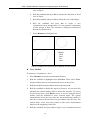
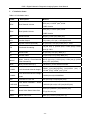
Revision History
Date
2008/10/23
2008/12/30
2009/04/24
ECO#
ECO-DUS-8001
ECO-DUS-8003
ECO-DUS-9003
Version
Description
V1.1
Added two obstetrical formulas.
Revised buttons’ function.
Added EMI& acoustic output affecting factors.
Revised specifications.
Added some precautions during puncture function.
Revised the auto-serial number when saving images.
Revised the labeling symbols.
Added daily check list.
Revised Probe Cleaning and Disinfecting.
V1.2
Added the Rx only information.
Revised the intended use.
Revised the symbols.
Revised the Configuration.
Revised the Life Period.
Revised the Cleaning and Disinfecting information.
Revised the Measurement Accuracy.
V1.3
Added the 3-Aixs (LWH) method, inputting focus, DICOM
function, file browsing, file sending, and transducer power
values;
Revised the preface and contact information, the range of
parameters, and the Cleaning and Disinfecting
information.
Add the silica gel pads.
II
Table of Contents
Chapter 1 Introduction................................................................................................................. 1
1.1. Intended Use..................................................................................................................... 1
1.2. Features ............................................................................................................................ 1
1.3. Model ............................................................................................................................... 1
1.4. Contraindication............................................................................................................... 2
1.5. General Safety Precaution Information............................................................................ 2
1.5.1. General Information ................................................................................................ 2
1.5.2. Biohazard Considerations ....................................................................................... 3
1.5.3. Electrical Safety ...................................................................................................... 4
1.6. Labeling Symbols............................................................................................................. 6
1.7. Electrical Safety Classifications....................................................................................... 7
1.8. Standards Compliance...................................................................................................... 8
Chapter 2 System Overview......................................................................................................... 9
2.1. Appearance....................................................................................................................... 9
2.1.1. Front Panel .............................................................................................................. 9
2.1.2. Rear Panel ............................................................................................................. 10
2.1.3. Right View (Dual Probe Sockets) ......................................................................... 11
2.2. Technical Specifications................................................................................................. 12
2.2.1. Power Supply ........................................................................................................ 12
2.2.2. Machine Specifications ......................................................................................... 12
2.2.3. General Technical Specifications .......................................................................... 12
2.2.4. Probe Specifications.............................................................................................. 13
2.3. Configuration ................................................................................................................. 14
2.3.1. Standard Configuration ......................................................................................... 14
2.3.2. Options .................................................................................................................. 14
Chapter 3 Transportation and Storage ..................................................................................... 17
3.1. Moving the System ........................................................................................................ 17
3.2. Storage............................................................................................................................ 17
3.3. Transportation ................................................................................................................ 17
Chapter 4 Installation Instructions ........................................................................................... 18
4.1. Environmental Requirements......................................................................................... 18
4.2. Unpacking Inspection..................................................................................................... 18
4.3. Connecting Procedure .................................................................................................... 18
4.3.1. Connecting or Disconnecting Transducers............................................................ 19
4.3.2. Rear Panel Connections ........................................................................................ 20
Chapter 5 System Control .......................................................................................................... 23
5.1. Powering the Device ...................................................................................................... 23
5.2. Examining ...................................................................................................................... 24
5.3. Screen Layout............................................................................................................... 24
5.4. Control Panel................................................................................................................ 26
5.4.1. Trackball................................................................................................................ 26
5.4.2. “0~9” Numeric Keys............................................................................................. 26
5.4.3. Alphabetic Keys .................................................................................................... 26
5.4.4. Function Controls.................................................................................................. 27
III
5.4.5. Adjustment Controls ............................................................................................. 33
5.4.6. Imaging Functions................................................................................................. 34
5.4.7. Additional Control Functions................................................................................ 35
5.5. Menu .............................................................................................................................. 36
5.6. Dialog Box Operation .................................................................................................... 38
5.7. Presetting........................................................................................................................ 39
5.7.1. Entering and Exiting ............................................................................................. 39
5.7.2. Displaying / Modifying the Preset Parameter ....................................................... 40
5.7.3. General Presetting ................................................................................................. 40
5.7.4. Presetting Exam .................................................................................................... 42
5.7.5. Presetting Formula ................................................................................................ 43
5.7.6. Presetting Post Processing..................................................................................... 45
5.7.7. Editing Comment Library ..................................................................................... 47
5.7.8. Presetting Data ...................................................................................................... 48
5.7.9. Presetting DICOM ................................................................................................ 48
5.7.10. Maintenance ....................................................................................................... 49
5.8. Printing........................................................................................................................... 49
Chapter 6 Operation ................................................................................................................... 51
6.1. Selecting an Examination Type...................................................................................... 51
6.2. Entering New Patient ..................................................................................................... 51
6.3. Entering or Editing Patient Information......................................................................... 51
6.4. Activating a Transducer ................................................................................................. 52
6.5. Selecting an Imaging Mode ........................................................................................... 52
6.6. Measurement and Calculation........................................................................................ 52
6.6.1. B-mode Generic Measurements............................................................................ 53
6.6.2. M-mode Generic Measurements ........................................................................... 62
6.6.3. General Report ...................................................................................................... 64
6.7. CINE Review ................................................................................................................. 65
6.8. File Management............................................................................................................ 66
6.8.1. Saving Images ....................................................................................................... 66
6.8.2. Opening Images .................................................................................................... 67
6.8.3. Browsing Images................................................................................................... 68
6.8.4. File Manager ......................................................................................................... 69
6.8.5. Sending Image / File ............................................................................................. 71
6.9. Puncture Function .......................................................................................................... 72
6.9.1. To Select the Angle of Needle Guide Line............................................................ 73
6.9.2. To Display or To Hide the Needle Guide Line...................................................... 73
6.9.3. To Adjust the Needle Guide Line.......................................................................... 73
Chapter 7 Obstetric Measurement and Calculation................................................................ 75
7.1. Abbreviations ................................................................................................................. 75
7.2. Obstetric Measurement and Calculation ........................................................................ 75
7.3. Fetus Growth Measurement ........................................................................................... 76
7.4. EDC Calculation ............................................................................................................ 77
7.4.1. EDC Calculation by LMP ..................................................................................... 77
7.4.2. EDC Calculation by BBT...................................................................................... 78
IV
7.5. EFW Calculation............................................................................................................ 78
7.5.1. Select a Formula in Preset..................................................................................... 78
7.5.2. Measurement Items ............................................................................................... 79
7.6. Results ............................................................................................................................ 79
7.6.1. Growth Curve........................................................................................................ 79
7.6.2. Obstetric Report .................................................................................................... 80
7.7. Others ............................................................................................................................. 83
Chapter 8 Cardiology Measurement and Calculation............................................................. 84
8.1. M-mode Cardiac Measurement and Calculation............................................................ 84
8.1.1. LV.......................................................................................................................... 89
8.1.2. Mitral Valve........................................................................................................... 91
8.1.3. Aortia..................................................................................................................... 92
8.1.4. LVMW, LVMWI ................................................................................................... 92
8.2. B-mode Cardiac Measurement and Calculation ............................................................ 93
8.2.1. LV.......................................................................................................................... 98
8.2.2. RV (Right ventricle internal diameter)................................................................ 100
8.2.3. PA (Aortic Pulmonary Artery)............................................................................. 100
8.3. Cardiac Report ............................................................................................................. 100
8.4. Others ........................................................................................................................... 103
Chapter 9 Gynecology Measurement and Calculation.......................................................... 104
9.1. Measurement and Calculation...................................................................................... 104
9.1.1. UT ....................................................................................................................... 105
9.1.2. Endo .................................................................................................................... 105
9.1.3. OV-V ................................................................................................................... 105
9.1.4. FO........................................................................................................................ 105
9.1.5. CX-L ................................................................................................................... 106
9.1.6. UT-L/CX-L.......................................................................................................... 106
9.2. Gynecologic Report ..................................................................................................... 106
9.3. Others ........................................................................................................................... 109
Chapter 10 Small Parts Measurement and Calculation .........................................................110
10.1. Measurement and Calculation................................................................................... 110
10.2. Small Parts Report......................................................................................................111
10.3. Others ........................................................................................................................ 112
Chapter 11 Urology Measurement and Calculation ...............................................................113
11.1. Measurement and Calculation...................................................................................... 113
11.2. Urologic Report............................................................................................................ 114
11.3. Others ........................................................................................................................... 116
Chapter 12 Orthopedics Measurement & Calculation...........................................................117
12.1. Measurement and Calculation................................................................................... 117
12.2. Orthopedics Report ................................................................................................... 117
12.3. Others ........................................................................................................................ 118
Chapter 13 Inspection and Maintenance .................................................................................119
13.1. Life Period................................................................................................................. 119
13.2. Daily Checklist.......................................................................................................... 119
13.3. Cleaning and Disinfection......................................................................................... 119
V
13.3.1. System Surface Cleaning ................................................................................. 120
13.3.2. Probe and Probe Holder Cleaning and Disinfecting ........................................ 121
13.3.3. Needle Guide Cleaning and Disinfecting......................................................... 124
13.3.4. Trackball Cleaning ........................................................................................... 124
13.3.5. Disinfectants..................................................................................................... 124
13.4. Maintenance .............................................................................................................. 125
Chapter 14 Troubleshooting..................................................................................................... 126
14.1. Checkup..................................................................................................................... 126
14.2. Troubleshooting ........................................................................................................ 126
Chapter 15 Warranty and Service Policy ............................................................................... 127
Appendix A: Ultrasound Intensity and Safety ....................................................................... 129
A1: Ultrasound in Medicine................................................................................................. 129
A2: Ultrasound Safety and the ALARA Principle ............................................................... 129
A3: Probe Acoustic Output Parameters List ........................................................................ 131
A3.1 : Test of Probe C361-1 ........................................................................................ 131
A3.2 : Test of Probe L741/E741 .................................................................................. 132
A3.3 : Test of Probe C341............................................................................................ 133
A3.4 : Test of Probe C321-1 ........................................................................................ 134
A3.5 : Test of Probe E611-1/6.0MHz under B-MODE................................................ 135
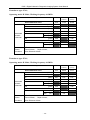
A4: Transducer Power Values .............................................................................................. 136
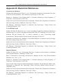
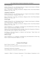
Appendix B: Obstetrical References ....................................................................................... 140
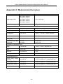
Appendix C: Measurement Accuracy ..................................................................................... 143
Appendix D: EMC Information-Guidance and Manufacture’s Declaration ...................... 144
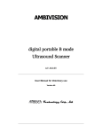
Appendix E: Order List............................................................................................................ 148
VI
DUS 3 Digital Ultrasonic Diagnostic Imaging System User Manual
Chapter 1 Introduction
1.1. Intended Use
The DUS 3 Digital Ultrasonic Diagnostic Imaging System is intended for diagnostic ultrasound
imaging analysis in gynecology rooms, obstetrics rooms, examination rooms, intensive care units,
and emergency rooms. The DUS 3 is intended for use by or on the order of a physician or
similarly qualified health care professional for ultrasound evaluation of Fetus; Abdomen;
Pediatrics; Small Organ; Neonatal Cephalic; Cardiology; Peripheral Vessel; Musculo-skeleton
(both Conventional and Superficial); Urology (including prostate); Transrecta and Transvagina
1.2. Features
This portable device, Digital Ultrasonic Diagnostic Imaging System (DUS 3), is a high-resolution
linear/convex scanning diagnostic apparatus.
Applied technologies:
Tissue Specific Imaging (TSI), Tissue Harmonic Imaging (THI), Digital Beam-Forming (DBF),
Dynamic Receiving Focusing (DRF), Real-time Dynamic Aperture (RDA), Dynamic Frequency
Scanning (DFS), and Dynamic Apodization.
Display modes:
B, B+B, 4B, B+M, and M.
Measurement and calculation functions:
B-mode generic measurement and calculation: Distance, circumference, area, volume, ratio, %
stenosis, and angle;
M-mode generic measurement and calculation: Time, slope, and heart rate.
File management:
It supports local disk and removable disk storage. USB 1.1 interface enables fast image uploading
to your computer in the real-time mode. It has huge storage capacity.
Operation:
The folding keyboard designed with trackball is easy and convenient for various types of
operation.
In addition, 10" non-interlaced progressive display and diverse probes are adopted to provide a
clear and stable image.
1.3. Model
DUS 3
-1-
DUS 3 Digital Ultrasonic Diagnostic Imaging System User Manual
1.4. Contraindication
The equipment is not applicable to the diagnosis of the pneumatic organs that contain gas
such as lung, stomach, intestines, etc.
It is recommended not to examine the parts with wounds or acute inflammation to avoid
cross infection.
Patients in the following situations are not allowed to be examined with E611-1 probe:
vaginal infection (such as trichomonal vaginitis, colpomycosis, venereal disease etc.), the
unmarried, vagina deformity, menstrual period, postmenopausal vagina atrophy, difficulty in
per vagina ultrasonic examination, colporrhagia, Pyrilamine placenta previa, etc.
1.5. General Safety Precaution Information
1.5.1. General Information
NOTE: This equipment is not intended for home use.
WARNING
CAUTION
: This equipment is not intended for treatment.
:
Federal (U.S.) law restricts this device to sale by or on the order of a
physician.
CAUTION
: The pictures and interfaces in this manual are for reference only.
The reliability of the device and the safety of operators and patients are considered during
product design and production. The following safety and preventive measures should be carried
out:
1.
The device should be operated by qualified operators or under their instructions.
2.
DO NOT alter parameters of the device at will. If it is necessary, please consult EDAN or
authorized representatives for service.
3.
The device has already been adjusted to its optimum performance. DO NOT adjust any
pre-set control or switch, unless it is listed in the manual.
4.
If the device breaks down, please shut down the machine immediately and contact EDAN or
authorized representatives.
5.
Only accessories supplied or recommended by EDAN can be used. Otherwise, the
performance and electric shock protection can not be guaranteed. If electrical or mechanical
equipment from other companies need to be connected to the device, please contact EDAN
or authorized representatives before connection.
6.
EXPLOSION HAZARD-Equipment is not suitable for use in the presence of a flammable
-2-
DUS 3 Digital Ultrasonic Diagnostic Imaging System User Manual
anesthetic mixture with air or with oxygen or nitrous oxide.
7.
Operating, storage and transportation environment of the device:
Operating environment:
Temperature: +5 °C ~ +40 °C
Relative humidity range: 25% RH ~ 80% RH
Atmospheric pressure range: 860 hPa ~ 1060 hPa
Maximum altitude: 3 Km
Storage and transportation environment:
Temperature: -40 °C ~ +55 °C
Relative humidity range: 25% RH ~ 93% RH
Atmospheric pressure range: 700 hPa ~ 1060 hPa
Maximum altitude: 3 Km
1.5.2. Biohazard Considerations
WARNING
:
1. This device is not suitable for intracardiac use or direct cardiac contact.
2. For neonatal head imaging, EDAN recommends that you exercise special care
during neonatal cephalic scanning to avoid possible damage to the posterior region
of the eye. The ultrasound energy emitted by the transducer easily penetrates the
fontanels of the infant.
3. EDAN makes every effort to manufacture safe and effective transducers. You must
take all necessary precautions to eliminate the possibility of exposing patients,
operators, or third parties to hazardous or infectious materials. These precautions
should be considered in the use of any application that may indicate the need for
such care, and during endocavity scanning; or when scanning patients with open
wounds.
Ultrasound may be harmful to human body. This device should be used for valid reasons,
for the shortest period of time, and at the lowest mechanical and thermal indices necessary to
produce clinically acceptable images. According to the ALARA (As Low As Reasonably
Achievable) principles, acoustic output should be set to the lowest level required to satisfactorily
perform the examination. Long time exposure should be avoided. For the parameters of sound
output, please refer to appendix A.
The DUS 3 complies with the requirements of applicable International Electrotechnical
Commission (IEC) standards in terms of safety and acoustic output levels.
-3-
DUS 3 Digital Ultrasonic Diagnostic Imaging System User Manual
1.5.3. Electrical Safety
WARNING
:
1. To ensure grounding reliability, only connect the system to a hospital-grade power
receptacle.
2. The AC power connector plug for the ultrasound system is a three-prong grounded
plug and should never be adapted to any two-prong (non-grounded) outlet, either by
modifying the plug or by using an adapter.
3. To avoid electrical shock, never modify the ultrasound system’s AC power circuits. To
ensure grounding reliability, connect the system only to an equivalent outlet.
4. SHOCK HAZARD-Do not attempt to connect or disconnect a power cord with wet
hands. Make certain that your hands are clean and dry before touching a power cord.
5. The equipment should be installed by a qualified service engineer. Do not try to
access the interior of the main unit. Only authorized service personnel could remove
the unit cover.
6. Before use, you must make sure that there is no visible evidence of damage on the
equipment, cables and probes which may affect patient safety or diagnostic capability.
The recommended inspection interval is once per week or less. If damage is evident,
replacement is recommended before use.
7. Equipment connected to the DUS 3 and located in the patient zone must be powered
from a medically-isolated power source or must be a medically-isolated device.
Equipment powered from a non-isolated source can Cause your system to exceed
leakage current limits. Enclosure leakage current created by an accessory or device
connected to a non-isolated outlet may add to the enclosure leakage current of the
imaging system.
8. Use an extension cord or multi-socket outlet setup to provide power to the ultrasound
system or to the system’s peripheral devices, may compromise the system grounding
and cause your system to exceed leakage current limits.
9. To avoid electrical shock and damage to the system, turn off and disconnect the
device from the AC power source before cleaning and disinfecting.
10. When more than one medical device is connected to the patient, leakage current of
the devices is summed together. Take caution.
11. Don’t touch the signal input or output connector and the patient simultaneously.
12. Periodically have the integrity of the system ground checked by a qualified service
engineer.
-4-
DUS 3 Digital Ultrasonic Diagnostic Imaging System User Manual
CAUTION
:
1. To avoid the possibility of electrostatic shock and damage to the system, avoid using
aerosol spray cleaners on the monitor screens.
2. DO NOT use spray cleaners on the system, as this may force cleaning fluid into the
system and damage electronic components. It is also possible for the solvent fumes
to build up and form flammable gases or damage internal components.
3. DO NOT use any fluid onto the system surface, as fluid seepage into the electrical
circuitry may cause excessive leakage current or system failure.
4. To ensure proper grounding and leakage current levels, it is the policy of EDAN to
have an authorized EDAN representative or an EDAN approved third party perform all
on-board connections of documentation and storage devices to the DUS 3.
5. The device and accessories are to be disposed of according to local regulations after
their useful lives. Alternatively, they can be returned to the dealer or the manufacturer
for recycling or proper disposal.
NOTE:
Please use the standard power cord as the input line of the network power supply for the
adapter to reduce risk.
Electromagnetic Compatibility (EMC)
Operating the DUS 3 in close proximity to sources of strong electromagnetic fields, such
as radio transmitter stations or similar installations may lead to interference visible on the
monitor screen. However, the device has been designed and tested to withstand such
interference and will not be permanently damaged.
EMI Limitations
Ultrasound machines are susceptible to Electromagnetic Interference (EMI) from radio
frequencies, magnetic fields, and transients in the air of wiring. Ultrasound machines also
generate EMI. The DUS 3 complies with limits as stated on the EMC label. However, there is no
guarantee that interference will not occur in a particular installation.
Possible EMI sources should be identified before the unit is installed.
Electrical and electronic equipment may produce EMI unintentionally due to one of the following
defects:
High frequency electrotome
Transformer
Defibrillator
Wireless LAN equipment
Medical lasers
Scanners
-5-
DUS 3 Digital Ultrasonic Diagnostic Imaging System User Manual
Cauterizing guns
Computers
Monitors
Fans
Gel warmers
Microwave ovens
Light dimmers
Portable phones
The presence of a broadcast station or broadcast van may also cause interference.
If you find strong interference shows on the screen, please check the sources.
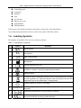
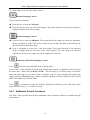
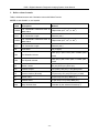
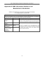
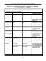
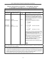
1.6. Labeling Symbols
Descriptions of symbols of the device are shown as below.
Table 1-1 Descriptions of Symbols
No.
Symbol
Serial Number
1
2
Definition
P/N
Part Number
3
Date of Manufacture
4
Manufacturer
5
Consult Instructions for Use
6
Symbol for “Caution, Consult Accompanying Documents”
7
Biological Risks
8
It indicates that the equipment should be sent to special agencies according
to local regulations for separate collection after its useful life and that this
equipment is put on the market after 13 August 2005.
9
General symbol for recovery / recyclable
10
Rx only (U.S.)
Federal (U.S.) law restricts this device to sale by or on the order of a
physician.
11
Authorized Representative in the European Community
12
The symbol indicates that the device complies with the European Council
Directive 93/42/EEC concerning medical devices.
-6-
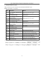
DUS 3 Digital Ultrasonic Diagnostic Imaging System User Manual
13
Type B, Applied Part
14
Alternating Current (a.c.)
15
ON (AC power supply)
16
OFF (AC power supply)
17
Equipotentiality
18
VGA
VGA output, External Monitor
19
Fuse
20
Probe socket
21
Net work port
22
Foots witch
To identify a foot switch or the connection for a foot switch.
23
Protective earth (ground)
24
Recording on an information carrier
25
Trademark
26
USB (Universal Serial Bus) Connection
27
Dangerous voltage
28
Variability, for rotating movement
Rotate clockwise to increase the value, and counterclockwise to decrease
the value.
29
Variability
Adjust right to increase the value, and left to decrease the value.
1.7. Electrical Safety Classifications
According to the type of protection against electric shock:
Equipment without internal power source,
Class I equipment.
According to the degree of protection against electric shock: Type B.
According to the degree of protection against harmful ingress of liquid:
IPX0, general equipment. But the probe can protect against splashing water, IPX4.
According to the degree of safety of application in the presence of a flammable gas:
-7-
DUS 3 Digital Ultrasonic Diagnostic Imaging System User Manual
Equipment not suitable for use in the presence of a flammable gas.
According to the mode of operation: Continuous operation.
According to the grade of EMC: Group I,Class A
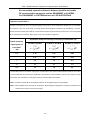
1.8. Standards Compliance
The DUS 3 is in compliance with the following standards.
Table 1-2 International Standards
Standard
Description
IEC 60601-1:1988+A1+A2
Medical electrical equipment; Part 1: General requirements for
safety
EN 60601-1:1990+A1+A2
IEC/EN 60601-1-2:2001+A1
Medical electrical equipment-Part 1-2: General requirements for
safety-Collateral standard: Electromagnetic compatibility
-Requirements and tests
IEC/EN 60601-1-4
Medical electrical equipment - Part 1-4: General requirements for
safety - Collateral standard: Programmable electrical medical
systems
IEC/EN 60601-2-37
Medical electrical equipment-Part 2-37: Particular requirements for
the safety of ultrasonic medical diagnostic and monitoring
equipment
IEC/EN 61157
Requirements for the declaration of the acoustic output of medical
diagnostic ultrasonic equipment
-8-
DUS 3 Digital Ultrasonic Diagnostic Imaging System User Manual
Chapter 2 System Overview
2.1. Appearance
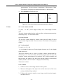
2.1.1. Front Panel
9
1
2
8
3
4
5
6
7
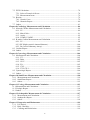
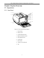
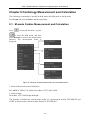
Figure 2-1 Front Panel Schematic Diagram
1
Probe holders
2
Display screen
3
Contrast adjustment knob
4
Brightness adjustment knob
5
Gain adjustment knob
6
Control panel
7
Power switch
8
Trough for the coupling gel
9
Grip
-9-
DUS 3 Digital Ultrasonic Diagnostic Imaging System User Manual
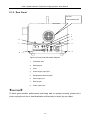
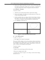
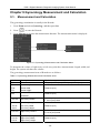
2.1.2. Rear Panel
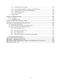
Air Fan:
Heat emission fan
1
2
8
3
7
4
6
5
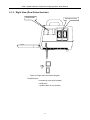
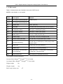
Figure 2-2 Rear Panel Schematic Diagram
CAUTION
1
Footswitch port
2
Network port
3
Fuse
4
Power supply input port
5
Equipotential earth terminal
6
VGA output port
7
Remote port
8
Video output port
:
To have good aeration performance and being able to operate normally, please don’t
cover or plug the air fan or heat dissipation orifice partly or wholly by any object.
- 10 -
DUS 3 Digital Ultrasonic Diagnostic Imaging System User Manual
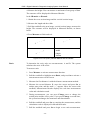
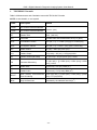
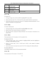
2.1.3. Right View (Dual Probe Sockets)
Probe Holder
Transducer Ports
Figure 2-3 Right View Schematic Diagram
Peripheral port:
2 transducer ports (dual sockets)
2 USB ports
1 probe holder (for two probes)
- 11 -
DUS 3 Digital Ultrasonic Diagnostic Imaging System User Manual
2.2. Technical Specifications
2.2.1. Power Supply
Power supply: a.c. 100~240V, 50Hz/60Hz, 110VA
2.2.2. Machine Specifications
Main unit dimensions: 353 mm (W) × 315 mm (L) × 253 mm (H)
Packaging dimensions: 500 mm (W) × 460 mm (L) × 465 mm (H)
Net weight: 11.5 Kg
2.2.3. General Technical Specifications
Table2-1 General Technical Specifications
Model
DUS 3
Monitor
10-inch non-interlaced progressive scanning black and white monitor
Resolution
800×575 pixels
Display Modes
B, B+B, 4B, B+M, and M
Image Gray Scale
256 levels
Image Magnification
×1.0, ×1.2, ×1.4, ×1.6,×2.0, ×2.4,×3.0, ×4.0 in distance (real time)
Storage
JPEG: 1000 frames; or BMP: 128 frames; or CIN: 128 frames
Depth Shift
B, B+B, 4B, B+M, M-modes in real time, in increments of 10 mm
Frame
Coefficient
Correlation
8 levels to adjust (0~7), (B, B+B, 4B, B+M-modes, ineffective when
freezing)
Image Conversion
Up/Down flip, Left/Right flip
Language Conversion
Chinese, English, French, Spanish, etc. (The language options varies with
language software installed.)
Acoustic power
16 levels to adjust (0~15)
Dynamic range
30dB~90dB (in 4 dB increments)
Focus position
16 levels to adjust
Focus number
Max. 4
Software packages
Abdomen, obstetric, small parts, gynecology, orthopedics, cardiology, and
urology
- 12 -
DUS 3 Digital Ultrasonic Diagnostic Imaging System User Manual
B-mode Measurement
Distance, circumference, area, volume, ratio, % stenosis, and angle
M-mode Measurement
Distance, time, slope, heart rate (2 cycles)
Annotations
Patient name, age, sex, time, date, hospital name, doctor name, comment
(full-screen character editing)
Body Mark
> 80 types
USB port
USB 1.1
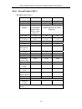
2.2.4. Probe Specifications
Supported probe type: convex, linear, micro-convex, endocavity (transvaginal, endorectal).
This device can detect the probe automatically.
The applications of the probes:
C361-1: Abdomen, Gynecology, Fetal / Obstetrics, and Pediatrics;
C341: Abdomen, Gynecology, Fetal / Obstetrics, and Pediatrics;
C321-1: Abdomen, Gynecology, Fetal / Obstetrics, Pediatrics and Cardiology;
E611-1 (Transvaginal / Transrectal): Gynecology, Fetal / Obstetrics, and Urology;
E741 (Transrectal): Rectum and the surrounding viscera, uterus, ovary and prostate;
L741: Small parts (galactophore, thyroid gland, prostate), Neonatal Cephalic, Peripheral Vascular,
Musculo-skeletal (both Conventional and Superficial).
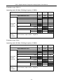
The probe specifications are as follows.
Table2-2 Probe Specifications
Specifications
Standard
Probe
Probe
Central frequency
Optional Probe
R60/3.5MHz
convex array
transducer
L43/7.5MHz
High frequency
linear array
transducer,
Endorectal
transducer
R20/3.5MHz
Microconvex array
transducer
R10/6.5MHz
Endocavity
transducer
R40/3.5MHz
convex array
transducer
C361-1
L741, E741
C321-1
E611-1
C341
3.5 MHz
7.5 MHz
3.5 MHz
6.5 MHz
3.5 MHz
Length of probe
cable
2200±50 mm
- 13 -
DUS 3 Digital Ultrasonic Diagnostic Imaging System User Manual
2.3. Configuration
2.3.1. Standard Configuration
1 DUS 3 main unit
1 convex array transducer: C361-1 (2.5/3.5/5.0MHz)
1 power cord (European Standard)
1 earth wire
1 probe holder
2 pieces of fuse, φ5×20, T1.6AL/250V
1 bottle of coupling gel 250mL
1 user manual
2 packing list
2.3.2. Options
The Digital Ultrasonic Diagnostic Imaging System supports the following options:
(1) Transducers
Convex array transducer C341 (2.5/3.5/5.0MHz);
Linear array transducer L741 (6.0/8.0/10.0MHz);
Endorecta transducer E741 (6.0/8.0/10.0MHz);
Endocavity transducer E611-1 (5.0/6.5/8.0MHz);
Micro-convex array transducer C321-1 (2.5/3.5/5.0MHz).
(2) Others
Ultrasonic Imaging Management System software specifications
Operating system: support WINDOWS 2000, WINDOWS XP, and WINDOWS VISTA.
Software function: image gathering, storage and playback; patient data management;
worksheet editing and printing, system analysis.
Video printer and USB printer are shown below.
Table2-3 Printers
Options
Recommended Models
Video printer
SONY UP-895MD
SONY UP-897MD
- 14 -
DUS 3 Digital Ultrasonic Diagnostic Imaging System User Manual
MITSUBISHI P93W
USB printer
HP DeskJet D2368 (parallel port / USB 1.1)
HP DeskJet D2468 (parallel port / USB 1.1)
HP DeskJet D2568 (parallel port / USB 1.1)
HP DeskJet D4368 (parallel port / USB 1.1)
HP LaserJet P2015 (parallel port / USB 1.1)
The video printer output: 110 × 82 mm; The USB printer output: A4 paper, 210 × 297 mm.
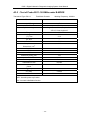
Puncture
Table2-4 Needle Guide Bracket Kit
Model
Name
Description
BGK-CR60
Needle Guide Bracket Kit
For the R60 probe, 4 vessels: 14G, 18G, 20G, 22G
BGK-CR40
Needle Guide Bracket Kit
For the R40 probe, 4 vessels: 14G, 18G, 20G, 22G
BGK-CR20
Needle Guide Bracket Kit
For the R20 probe, 4 vessels: 14G, 18G, 20G, 22G
BGK-CR10
Needle Guide Bracket Kit
For the R10 probe, 4 vessels: 14G, 18G, 20G, 22G
BGK-LA43
Needle Guide Bracket Kit
For the L43 probe, 4 vessels: 14G, 18G, 20G, 22G
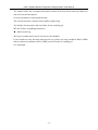
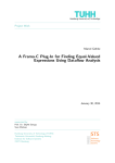
The puncture frame of BGK-CR60 is shown below.
Figure 2-4 Puncture Frame of BGK-CR60
DICOM 3.0
Footswitch
Single-pedal footswitch
MT-802 Mobile trolley
- 15 -
DUS 3 Digital Ultrasonic Diagnostic Imaging System User Manual
The mobile trolley has a compact and mobile console with four wheels and four brakes for
safe and convenient transport.
It can be assembled or disassembled easily.
The external structure complies with usability engineering.
Two holders for the probes and one holder for the coupling gel.
MT-802 Trolley Assembling Instruction
Hand carried bag
The bag is portable and it can be carried over the shoulder.
It can contain not only the main unit but also two probes (an array transducer R60/3.5MHz
and an endocavity transducer R10/6.5MHz) and one bottle of coupling gel.
It is watertight.
- 16 -
DUS 3 Digital Ultrasonic Diagnostic Imaging System User Manual
Chapter 3 Transportation and Storage
3.1. Moving the System
Digital Ultrasonic Diagnostic Imaging System is designed to be portable and easily transported
between sites. Power off the system and secure all accessories before moving it to another
location.
CAUTION
:
1. DO NOT park, or leave unattended, on a slope. Even when the wheel brakes are
engaged, the system may slide down a ramp.
2. Switch off the ultrasound system. Unplug the power cord from the power source and
secure the power cable.
3. Put the probes in the probe holder, or remove them and place them in the protective
carrying cases.
4. Disconnect and secure the footswitch and the connecting cable.
5. Raise the brakes away from the front and back caster wheels.
6. Push the handle to roll the system forward and maneuver it to its new location and
lock the wheel caster brakes.
7. Connect optional system accessories, such as the single-pedal footswitch.
8. Secure the system and complete the system setup, and then perform all the daily
checklist items before using it.
3.2. Storage
DO NOT place the device near the ground, walls or roof.
Keep good indoor ventilation. Avoid strong and direct sunlight, and erosive gas.
3.3. Transportation
To prepare the system for shipment over long distance or rough terrain, repack the system in the
factory packing and crate.
To prepare the system for transport over distances: load the system into a vehicle using a lift gate.
To prevent lateral movement of the system, secure the system with cargo straps. To prevent
sudden jarring of the system during transport, provide shock cushions beneath the system.
It is suitable for transportation by air, railway, highway and ship. Avoid splashing with rain and
snow, inversion, and collision.
- 17 -
DUS 3 Digital Ultrasonic Diagnostic Imaging System User Manual
Chapter 4 Installation Instructions
4.1. Environmental Requirements
Keep the device away from equipment with strong electric field, strong magnetic and high
voltage field, and protect the display screen from direct exposure to strong sunlight. Keep good
ventilation.
4.2. Unpacking Inspection
After unpacking the device, customers should follow the PACKING LIST to check the product
carefully and to make sure that no damage has occurred during transportation. Then, install the
device according to the installation requirement and method.
WARNING
:
1. DO NOT use the device if it is found to be damaged or defective.
2. DO NOT drop or collide with the probe, otherwise you shall give up using it.
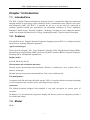
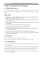
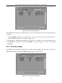
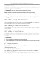
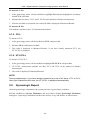
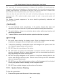
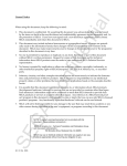
Note: there are two standby silica gel pads for the system. If necessary, stick them on the
rear surface of the keyboard to avoid abrasion, as shown below.
Silica gel pad
4.3. Connecting Procedure
1.
Take the main unit and accessories out of the package.
2.
Connect the transducers to the main unit correctly.
- 18 -
DUS 3 Digital Ultrasonic Diagnostic Imaging System User Manual
3.
Connect the printer and load the recording paper.
4.
Connect the power cable
1) Connect the earth wire between the main unit and the common grounding terminal firmly.
2) Plug one end of the power cable to the power socket of the main unit, the other end to the
special power output socket of the hospital.
5.
Switch on the main unit.
Press the power switch on the left side of the panel. You can operate the main unit after the
main interface appears.
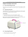
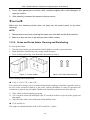
4.3.1. Connecting or Disconnecting Transducers
NOTE:
Ensure that the system is shut down before connecting and disconnecting transducers.
Flip images horizontally to change the scan direction or vertically to change the image orientation.
The scan direction mark located at the side of probe indicates the beginning direction of scanning.
The scan direction mark is as shown below.
Scan Direction Mark
Figure 4-1 Probe Scan Direction Mark Schematic Diagram
There is information about Model and SN on the probe.
To connect a transducer:
1.
Place the transducer’s carrying case on a stable surface and open the case.
2.
Carefully remove the transducer and unwrap the probe cable.
3.
DO NOT allow the transducer head to hang free. Impact to the transducer head could result
in irreparable damage.
4.
Turn the connector locking handle to the OPEN position.
5.
Align the connector with the transducer port and carefully push into place.
6.
Turn the locking handle on the transducer connector clockwise to the LOCK position. This
ensures the connector in position and ensures the best possible contact.
7.
Place the transducer in the transducer holder.
- 19 -
DUS 3 Digital Ultrasonic Diagnostic Imaging System User Manual
To disconnect a transducer:
1. Turn the locking handle on the connector housing counterclockwise to the OPEN position.
2. Firmly grasp the transducer connector and carefully remove it from the system port.
3. Store each transducer in its protective carrying case.
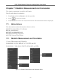
Locked
Figure 4-2 Transducer Ports
WARNING
Unlocked
Figure 4-3 Locked and Unlocked Positions of the Probe Connectors
:
DO NOT touch the pin of probe connector.
CAUTION
:
DO NOT plug or pull out the connector when the device is activated. This is to avoid
uncontrollable damage to the probe and the main unit.
NOTE:
Once the probe is connected to the main unit, please do not reinstall it frequently. This is
to avoid poor contact between the probe and the main unit.
4.3.2. Rear Panel Connections
Video connections are located on the rear panel of the DUS 3.
WARNING
:
Accessory equipment connected to the analog and digital interfaces must be certified
according to the respective IEC/EN standards (e.g. IEC/EN 60950 for data processing
equipment and IEC/EN 60601-1 for medical equipment). Furthermore, all configurations
shall comply with the valid version of the standard IEC/EN 60601-1-1. Therefore,
anybody, who connects additional equipment to the signal input or output connector to
configure a medical system, must make sure that it complies with the requirements of the
valid version of the system standard IEC/EN 60601-1-1. If in doubt, consult our technical
service department or your local distributor.
- 20 -
DUS 3 Digital Ultrasonic Diagnostic Imaging System User Manual
CAUTION
:
To ensure proper grounding and leakage current levels, it is the policy of EDAN to have
an authorized EDAN representative or EDAN approved third party perform all on-board
connections of documentation and storage devices to the DUS 3.
Figure 4-4 Rear Panel Connections
Peripheral port:
1 remote port
1 video output port
1 foot switch port
1 VGA output port (15 pin)
1 Network port (DICOM 3.0)
1 power supply input port
2 fuses, φ5×20, T1.6AL/250V
1 equipotential earth terminal
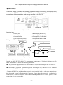
Equipotential Bonding
Rear panel
Equipotential bonding conductor
Equipotential terminal
Other device
VGA output
Equipotential terminal
Figure 4-5 Equipotential Bonding
Any use of other devices with the system is at the user’s risk and may void the system warranty.
In order to fulfill IEC/EN 60601-1-1 requirements, connections of peripheral equipment to the
DUS 3 must adhere to one of the following conditions:
The peripheral equipment itself is a medical device approved according to IEC/EN 60601-1.
Non-medical peripheral equipment approved according to any other EN or IEC standard
must use the following setup for connection:
-Connect the DUS 3 to an independent protective earth terminal with an earth wire connection to
the ultrasound system’s Equipotential Connector. Ensure that the protective earth wire is
connected to a qualified protective earth connection independent of the existing system’s earth
connection (via the power cable).
- 21 -
DUS 3 Digital Ultrasonic Diagnostic Imaging System User Manual
-The peripheral equipment is located at least 1.5 meters (1.8 meters in Canada and the U.S.A)
outside the patient environment. A patient environment is defined as the area in which medical
examination, monitoring, or treatment of the patient takes place.
-The peripheral equipment is connected to a main outlet outside the patient environment but still
within the same room as the ultrasound system.
WARNING
:
1. Equipotential bonding: When the device is running with other instruments jointly,
consideration should be given to equipotentiality.
2. Doctors and patients might be exposed to the hazardous and uncontrollable effects of
compensating current caused by unbalanced equipotentiality between indoor medical
device and touchable conducting parts. The safest solution is to build a unified
equipotential network, to which the medical device is connected, using an angular
plug.
Printer Installation
This system supports video printer and USB printer.
To install the video printer:
1. Power off the main unit and the printer.
2. Connect the VIDEO IN (video input) of the video printer with the
Reference
VIDEO OUT (video output) of the main unit.
3. Connect the REMOTE of the video printer with the REMOTE of the
1. Figure 2-2 Rear
main unit.
Panel Diagram.
4. Power on the main unit and run the printer.
To install the USB printer:
1. Power off the main unit and the printer.
2. Connect the printer with the main unit by using a USB cable.
3. Power on the main unit and run the printer.
2. Chapter 5.7.3,
General
Presetting.
If the printer can not work normally, check the printer presetting.
NOTE:
If you want to use the multiple portable socket-outlet to supply power to the whole DUS 3
system, you are suggested to calculate the system power consumption when building a
DUS 3 system so as to match the system power consumption with the power sustained
by the Multiple portable socket-outlet.
- 22 -
DUS 3 Digital Ultrasonic Diagnostic Imaging System User Manual
Chapter 5 System Control
5.1. Powering the Device
To power on the device
Before powering on this device, check as below:
1. Check all the cables and make sure there is no scrape or crack.
2. Check the control panel and the monitor and make sure there is no crack.
3. Check the probe and the connection and make sure there is no scrape or crack.
4. Check the power socket and the switch and make sure there is no damage.
To power on:
1. Connect one end of power cable at the rear panel of the device, and the other end to the
standard three-pin power supply socket.
2. Switch on, and then the power indicating light on the panel is on, and a startup interface
appears.
To shut down the device:
After using it, switch off power supply. The power indicating light on the panel is off.
NOTE:
Please unplug the AC power cord from the power socket if the device is to remain idle for
a long time.
CAUTION
:
1. You are forbidden to unplug or plug the power cord before switching off the system.
2. Wait approximately five seconds between powering the system off and then on again.
This allows the system to complete its shutdown sequence.
To restart the device:
If there is any trouble described as below, please switch off the device and then power on the
device to restart.
1.
The device displays wrong information and it lasts a long time.
2.
The device displays abnormally.
3.
The device can not execute an operation.
- 23 -
DUS 3 Digital Ultrasonic Diagnostic Imaging System User Manual
5.2. Examining
Apply an appropriate amount of coupling gel (medical ultrasound coupling agent) to the body
area to be examined, and then contact the area with the acoustic window of the probe firmly. A
cross-sectional image of tissues is displayed on the screen. Adjust the brightness, contrast, gain,
TGC, acoustic output, dynamic range, and focus combination properly. Adjusting the
monitor’s contrast and brightness is one of the most important factors for proper image quality. If
theses controls are set incorrectly, the gain, TGC, dynamic range, focus combination and even
acoustic output may have to be changed more often than necessary to compensate. Meanwhile,
properly move the probe to obtain an optimal image of the target area. Or if necessary, adjust
sweeping speed to get satisfying images in the M-mode.
CAUTION
:
1. Please be gentle when contacting the target area with a probe. This is to avoid
making the probe damaged or the patient disturbed.
2. Please choose a proper probe for the target area with an appropriate frequency to
begin the diagnostic operation.
3. Adjust the total gain (Gain) knob slowly.
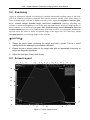
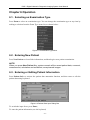
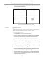
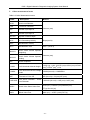
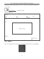
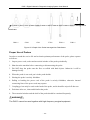
5.3. Screen Layout
1
2
3
4
5
6
7
8
9
10
11
24
12
23
22
21
13
20
19
14
18
17
16
Figure 5-1 Typical Image Screen
- 24 -
15
DUS 3 Digital Ultrasonic Diagnostic Imaging System User Manual
1
Manufacturer logo
2
Hospital name
3
Patient name
4
Patient ID
5
Type of current probe
6
G, AP, IP, FR
7
Transmitting frequency
8
TSI
9
THI
10
The freeze symbol
11
Time and date
12
Menu window
13
Measured Results window
14
Depth of current image
15
The USB connecting symbol
16
Operation prompt instruction window
17
The cine review symbol
18
Examination type
19
Body mark
20
Probe symbol
21
Focus (Current Focus Position and Number)
22
Gray bar
23
Image window
24
Probe direction
- 25 -
DUS 3 Digital Ultrasonic Diagnostic Imaging System User Manual
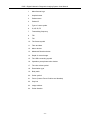
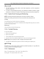
5.4. Control Panel
Power Indicator
TGC Buttons
Figure 5-2 Control Panel Schematic Diagram
Trackball
5.4.1. Trackball
The trackball is easy and convenient to operate. It can achieve the following functions:
Move the measurement cursor during measurement.
Move to select menu items in menu-based operations.
Move the comment cursor in the comment status.
Move the M Mark in the B/M-mode.
Realize single frame playback in the frame-by-frame playback status.
Move the zoomed window in the zoom status.
NOTE:
1. Please be gentle when running the trackball.
2. Please keep the surface of trackball clean.
5.4.2. “0~9” Numeric Keys
Numbers are used for calibrating time, data settings, age notation, and comment adding etc.
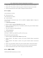
5.4.3. Alphabetic Keys
The system supports some language-specific characters through the use of SHIFT with a
combination of keys on the keyboard. Press any of these keys in the annotation mode and
comment mode to display the corresponding character on the cursor position.
Table 5-1 German and French Characters
- 26 -
DUS 3 Digital Ultrasonic Diagnostic Imaging System User Manual
German Characters
French Characters
Symbol
Key Combination
Symbol
Key Combination
ä
SHIFT-A
è
SHIFT-Z
ö
SHIFT-S
à
SHIFT-X
ü
SHIFT-D
ó
SHIFT-C
β
SHIFT-F
é
SHIFT-V
ñ
SHIFT-G
ç
SHIFT-B
ø
SHIFT-H
å
SHIFT-N
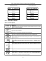
5.4.4. Function Controls
Table 5-2 Function Controls
Key
Description
Space key
Press this key in the annotation mode and comment mode to introduce a blank
space on the cursor position.
+ Alphabetic key combination
Press SHIFT and alphabetic key corresponding language’s special character.
Alphabetic Shift key
It is used to switch the characters between lowercase and uppercase.
Entering key
In annotation mode and comment mode, press this key to move the cursor to
insert a blank line.
Delete key
In annotation mode and comment mode, press this key to delete text word by
word.
Arrow key
In annotation mode and comment mode, press these arrow keys to move the
comment cursor.
Press it to clear all the measurements, calculations, comments, or body marks
on the screen.
New Patient key
Press this key to cancel all the recent patient data, comment, measurement,
calculation and worksheet, except saved images.
- 27 -
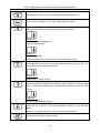
DUS 3 Digital Ultrasonic Diagnostic Imaging System User Manual
Patient information annotation key
Press this key to open or to close the Patient Data Input Dialog box.
Examine Menu key
Press this key to display or to exit the examination type menu.
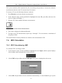
System Control key
Press this key to enter or to exit the file management system;
Reference
Chapter 6.8, File Management.
Or to do the presetting.
Reference
Chapter 5.7, Preset.
When entering the file menu, you can not use other function keys.
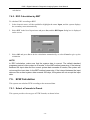
Snapshot key
Press this key to save the current image. But after entering the file menu, you
can’t use this to save the current image.
Reference
Chapter 6.8.1, Saving Images.
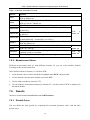
Probe Switch key
Diverse probes are available for this device. Press this key to select a proper
type of connected probe with the corresponding information in the top right
corner.
Reference
Figure 5-1 Typical Image Screen.
Frequency Shift Key
Press this key to switch to the proper operating frequency for the activated
probe.
When you change the frequency, the G changes simultaneously.
Image up/down Flip key
Press this key to flip the image vertically.
- 28 -
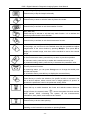
DUS 3 Digital Ultrasonic Diagnostic Imaging System User Manual
Image left/right Flip key
Press this key to flip the image horizontally.
Cine key
Press this key to enter or exit the frame-by-frame cine mode.
Comment key
Press this key to activate or exit the annotation function.
Body Mark Key
Press this key to activate or exit the body mark function. It is to indicate the
examine position and the scan direction.
Measure key
Press this key to activate or exit the measurement function.
In the real-time status, press this key to activate a zoom window in the middle
of the image, you can move it to the desired area with the trackball and adjust
magnification of the zoom window by pressing Multiple. Then press Set to
display the zoomed image, and then roll the trackball to move the zoomed
image
Back key
In the measurement status, press this key to return to previous operation.
In comment mode, press the key to delete the entered text one by one.
In parameter setting status, press the key to decrease the parameter value.
Change
This key has dual functions.
In measuring status, you can press Change once to change the settled point
and the active point.
In annotation status, press this key to display the comment library.
Set key
Press this key to confirm the selection of a specific function or command. Use
this to anchor calipers, select a menu item or image graphics. Or press it to
increase the parameter value in the parameter setting status.
Freeze key
Press this key to switch between the frozen and real-time states. When an
image is frozen, the system inserts “
” next to the system time clock and the
clock pauses. When unfreezing the system, all the measurements,
calculations, body marks, and comments are erased.
Print key
Press this key to do the video printing.
/
Footswitch
Pedaling on the footswitch is equivalent to pressing Freeze.
- 29 -
DUS 3 Digital Ultrasonic Diagnostic Imaging System User Manual
Comment function
The comment library is for positions and anatomical structures.
To activate the comment function:
Press Comment, and there is a cursor “І” displayed in the image area for annotating by the
following ways:
Enter text directly onto the image using the keyboard.
Insert system-defined or user-defined comment phrases by pressing Change to display the
comment library.
During commenting, you can use Delete to cancel the undesired text word by word, or you can
use Back to cancel the undesired text one by one.
Generic
Abd 1
Abd 2
OB
Cardiac
Sml
- 30 -
DUS 3 Digital Ultrasonic Diagnostic Imaging System User Manual
Lesion 1
Lesion 2
Figure 5-3 System-defined Comment Library
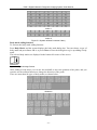
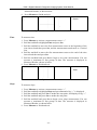
Body mark adding function
To activate the body mark adding function:
Press Body Mark, and the system displays the body mark dialog box. You can choose a type of
body mark and press Set to add it, or press Close to close the dialog box to give up adding a body
mark.
The selected body marks are displayed in the bottom left corner of the screen.
Reference
Figure 5-1 Typical Image Screen.
After adding a body mark, you can use the trackball to move the position of the probe, and you
can also use the rotation function to change the direction of the probe.
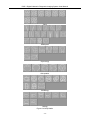
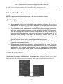
There are more than 80 types of body marks, as shown below:
Abdomen
Obstetric
- 31 -
DUS 3 Digital Ultrasonic Diagnostic Imaging System User Manual
Twins
Small parts
Gynecology
Orthopedics
Cardiology
Urology
Figure 5-4 Body Marks
- 32 -
DUS 3 Digital Ultrasonic Diagnostic Imaging System User Manual
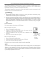
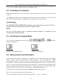
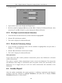
5.4.5. Adjustment Controls
Focus Position adjustment button
Press the button to switch the position of the current focus. 16 segments of the adjustable
electronic focus are provided by the device. By adjusting the focal point, a clear image can be
obtained. The current focal point is as shown in the FOCUS position on the left of the screen.
Image Processing adjustment button
Press the button to do the image processing that has 8 levels, ranging from 0 to 7.
Depth adjustment button
Press this button to adjust the scanning depth, in increments of 10 mm. The current depth is
displayed in the bottom right corner of the image.
Multiple function button
This button has three functions:
In the zoom status, press this button to adjust the magnification, 1.0, 1.2, 1.4, 1.6, 2.0, 2.4,
3.0 or 4.0.
When a body mark is added, the rotation function is automatically activated. You can press
this button to adjust the scanning direction.
When an arrow is added (press Comment to activate the comment function, and then press
Set to add an arrow), the rotation function is automatically activated. You can press this
button to adjust the arrow direction.
- 33 -
DUS 3 Digital Ultrasonic Diagnostic Imaging System User Manual
Adjustment knobs near the screen:
Contrast: rotate this knob to adjust the contrast.
Brightness: rotate this knob to adjust the brightness.
Gain: rotate this knob to adjust the total gain (overall gain), 0 ~ 98, in increments of 2.
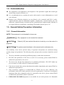
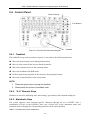
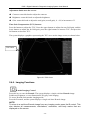
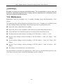
Time Gain Compensation (TGC) buttons:
Press the buttons to adjust the TGC. Press the upper buttons to adjust the near field gain, and the
lower buttons to adjust the far field gain; press the right buttons to increase TGC, and press the
left buttons to decrease TGC.
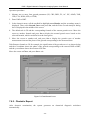
The system displays a graphics representing the TGC curve on the image screen, as shown below.
TGC curve
Figure 5-5 TGC Curve
5.4.6. Imaging Functions
B-mode Imaging Control
Press this key to enter the B-mode. The system displays a single real-time B-mode image.
B indicates brightness, or two-dimensional (2D) gray scale imaging.
To access B-mode from another imaging mode:
Press the B control, and the system displays a single real-time B-mode image.
NOTE:
To return to a real-time B-mode image from any imaging mode, press the B control. This
also deletes all measurements, calculations, comments, and body marks that are
displayed on the screen.
- 34 -
DUS 3 Digital Ultrasonic Diagnostic Imaging System User Manual
To exit B-mode, press any other mode control.
2B-mode Imaging Control
This key has two functions:
Press this key to enter the 2B-mode.
Press this key to active one of the dual images. The probe direction of the activated image is
brighter than that of the frozen image.
4B-mode Imaging Control
Press this key to enter the 4B-mode. The system divides the image area into four quadrants:
the first quadrant is on the top left, the second on the top right, the third on the bottom left,
and the fourth on the bottom right.
Press it repeatedly to active one of the four images. The probe direction of the activated
image is brighter than the direction of the frozen images. The four images are obtained
respectively and only one image at a time is displayed in real-time.
B/M-mode and M-mode Display Control
Press
to cycle among the B/M mode or the M mode.
Press it once to enter B/M mode, the B mode and M mode images are displayed on the screen at
the same time(Abbreviated as B/M or B+M).The left image is a real-time image of B mode,
while the right image is a real-time image of M mode. There is a line constituted by points with
regular spacing on B-mode image, which is called the M Mark. Roll the trackball to move the M
Mark. Press Set to locate the M Mark.
Press
a second time to enter the M mode. It displays an M-mode sweep. The slope of this
mode has four levels: 3, 6, 15 and 25 seconds.
5.4.7. Additional Control Functions
The DUS 3 also provides the following additional control functions, which are available through
status menus.
- 35 -
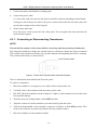
DUS 3 Digital Ultrasonic Diagnostic Imaging System User Manual
Table 5-3 Additional Control Functions
Control function
Angle (sector
scan width)
Description
angle/
Adjusts the sector angle for curve transducers, and the scan width for linear
transducers.
F. Number
Adjusts the focus number.
A. Power
Adjusts the acoustic power.
Scan Mode
Selects the scan mode, High density or High FPS (frame rate, in frames per
second)
Dynamic Range
Controls the overall contrast resolution of B-mode and M-mode images.
Edge Enhance
Improves the contour enhancement of the image for distinguishing the
edges of a structure in B-mode.
Smooth
Adjusts the smooth level.
Persist
Selects the number of frames for frame averaging.
Line Average
Adjusts the line average level.
Rejection
Adjusts the rejection level.
Gray Map
Selects the post-processing gray curve map.
THI
Selects the THI type, tissue harmonic imaging / general.
TSI
Selects the TSI type, general/muscle/fatty/fluid.
M Sweep
Adjusts the scrolling speed level of the M-mode sweep.
M Mark
Adjusts the M Mark of the B/M mode.
These functions can be set using Set and Back.
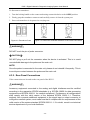
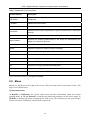
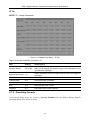
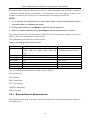
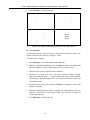
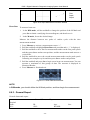
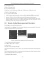
5.5. Menu
Menus are displayed on the right of the screen. Only one menu can be activated at a time. The
types are as shown below:
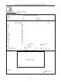
System status menu
In B-mode or B/M-mode, the system status menu provides information about the current
imaging mode. In 2B and 4B-mode, it indicates the status and parameters of the active image. In
M-mode, it indicates the status and parameters of M sweep. The following are the system status
menus of B-mode, B/M-mode, and M-mode respectively.
- 36 -
DUS 3 Digital Ultrasonic Diagnostic Imaging System User Manual
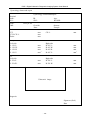
Figure 5-6 System Status Menu
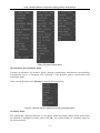
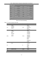
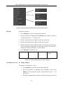
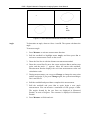
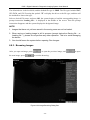
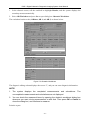
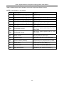
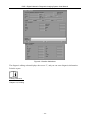
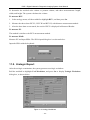
Measurement and calculation menu
Executes an operation. For instance, begin a distance measurement, and then the corresponding
measurement cursor is displayed. The following is the B-mode generic measurement and
calculation menu.
After entering B-mode, press Measure to display the menu below.
Figure 5-7 B Mode Generic Measurement and Calculation Menu
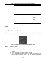
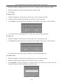
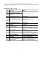
Secondary menu
The symbol “►” indicates that there is a secondary menu associated with the menu option. Roll
the trackball to highlight the menu option with “►”, the system displays a secondary menu for
the selected option.
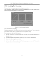
- 37 -
DUS 3 Digital Ultrasonic Diagnostic Imaging System User Manual
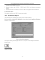
Example: The secondary menu of Cir/Area contains Ellipse and Trace, as shown below.
After entering B-mode, press Measure to display the menu below, and highlight the option
Cir/Area, the system displays the secondary menu Ellipse and Trace.
Figure 5-8 Secondary Menu
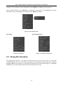
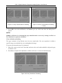
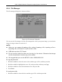
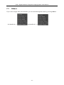
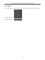
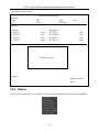
File menu
Needle guide menu
Figure 5-9 File Menu
Figure 5-10 Needle Guide Menu
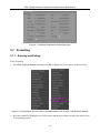
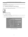
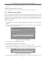
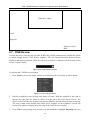
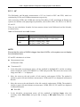
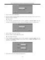
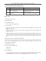
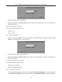
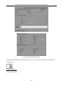
5.6. Dialog Box Operation
The dialog box may have a few tabs, as shown below. You can select one tab at a time with
trackball and Set. Also, you can modify the parameter following the prompt instruction, and then
highlight OK and press Set to save the modified parameters and close the dialog box; or highlight
Cancel to give up the modification and close the dialog box directly.
- 38 -
DUS 3 Digital Ultrasonic Diagnostic Imaging System User Manual
Figure 5-11 Obstetric Examination Preset Dialog Box
5.7. Presetting
5.7.1. Entering and Exiting
Enter presetting:
1. Press File, highlight Preset, and then press Set to display the preset menu, as shown below.
Figure 5-12 Preset Menu (the left—with no DICOM installed, and the right—with DICOM installed)
2. Roll the trackball to highlight one of the options and then press Set to display the menu of the
corresponding option.
- 39 -
DUS 3 Digital Ultrasonic Diagnostic Imaging System User Manual
To exit presetting:
Highlight Return and press Set. Then the system restarts automatically. The system runs with the
new modified parameters after being restarted.
5.7.2. Displaying / Modifying the Preset Parameter
Select a type of presetting and press Set to display the corresponding dialog box, and you can
modify the parameter following the prompt instruction.
Reference
Chapter 5.6, Dialog box operation.
5.7.3. General Presetting
1. In preset menu, move the cursor to highlight General and press Set to display general
presetting dialog box, as shown below.
2. Roll the trackball to highlight an item and then press Set. Then use the keyboard to enter text.
Figure 5-13 General Presetting
- 40 -
DUS 3 Digital Ultrasonic Diagnostic Imaging System User Manual
Table 5-4 General Presetting Information
Item
Setting
Allows you to
Hospital Name
Input freely
Set hospital name displayed on the top left of the
screen and diagnosis report, with a maximum of
32 characters.
Default Exam
Abdomen, obstetric, small
parts, gynecology, urology.
orthopedics, or cardiology.
Preset the examination type.
Language
Chinese, English, French,
Spanish, etc.(The language
options varies with language
software installed.)
Set the overlay language
Video Mode
PAL
Set video mode.
SnapShot Type
BMP/JPG
Set the snap shot type.
Keyboard
Sound
√/ Null
Turn on or off the keyboard sound.
Report Printer
Report printer
Select the printer type.
Print
Image
Select whether to print image
in report.
Select whether to print image in report when
printing by USB printer.
Date Format
Set freely
YYYY/MM/DD, MM/DD/YYY or DD/MM/YYYY.
Date
Set freely
Set the system date.
Time
Set freely
Set the system time, format: H/M/S.
SnapShot
Device
USB-Disk/Fixed
Set the snap shot device.
System Sleep
√/ Null
Select whether the device enters sleep mode
when no operation is done for certain minutes.
Waiting time
Set freely
Set the system waiting time to enter sleep mode
(5-60 min).
Refresh Speed
1~10
Set the grade of glint speed of system dormancy.
Report
You must restart the system to validate the change, including Language, Video Mode,
Keyboard Sound, and Report Printer. After you perform those presets, and press Return, the
system pops up a dialog box to prompt you whether to restart the system, as shown below.
- 41 -
DUS 3 Digital Ultrasonic Diagnostic Imaging System User Manual
5.7.4. Presetting Exam
Examination types include abdomen, obstetric, small parts, gynecology, orthopedics, cardiology,
and urology. Take obstetric examination preset for example, in the preset menu, move the cursor
to highlight Obstetric and press Set to display obstetric examination presetting dialog box.
Parameter Tab
Figure 5-14 Obstetric Presetting -- Parameter Tab
Table 5-5 Obstetric Presetting Information – Parameter
Item
Setting
Allows you to
Display
B, M, B+B, 4B, B+M
Set display mode type.
Depth
40~240 mm (C361-1)
Set examine depth.
A Power
0~15
Set acoustic power, 16 levels.
Focuses Num
1/2/3/4
Set the number of focuses.
Scan Density
High density/high frequency
Set scanning density.
Scan Angle
0/1/2/3
Set scanning angle.
THI
Tissue harmonic imaging /
General
Set THI.
Line Persist
0~7
Set image line correlation.
H Reverse
√/ Null
Set the attribute of Horizontal reversal.
Probe
Display all the probe type
this device supports
Set the probe type to use.
Freq
F1/F2/F3
Set the frequency of probe.
Post Process
Gray map (L, A, B, C, D, S)
Select a default gray map.
IP
0~7
Set the image parameter.
M speed
1/2/3/4
Set the M-mode sweeping speed.
Gain
0~98
Set the gain of image, in 2 increments.
TSI
General/muscle/fatty/fluid
Set the type of TSI.
V Reverse
√/ Null
Set the attribute of Vertical reversal.
- 42 -
DUS 3 Digital Ultrasonic Diagnostic Imaging System User Manual
IP Tab
NOTE: IP----Image Parameter
Figure 5-15 Obstetric Presetting -- IP Tab
Table 5-6 Obstetric Presetting Information – IP
Item
Setting
Allows you to
Dynamic Range
30~90 dB
Select the default dynamic range for the examination, in decibels
(dB). During imaging, the dynamic range can be adjusted in 4 dB
increments to the image.
Edge Enhancement
0~7
Select the default amount of edge enhancement to be applied to
the image.
Smooth
0~7
Set image smoothing.
Frame Persist
0~7
Set image frame correlation.
Line Average
0~7
Set image line softening attribute.
AGC
0~3
Set Automatic Gain Control.
Rejection
0~7
Set image noise restrain attribute.
5.7.5. Presetting Formula
In the preset menu, move the cursor to highlight Formula and press Set to display formula
presetting dialog box, shown as below.
- 43 -
DUS 3 Digital Ultrasonic Diagnostic Imaging System User Manual
Figure 5-16 Formula Presetting
Table 5-7 Formula Presetting Information
Parameter
GS
BPD
References
Tokyo
Hellman
Rempen
China
Tokyo
Hadlock
Merz
Rempen
Osaka
China
Parameter
References
CRL
Tokyo
Hadlock
Hansmann
China
Robinson
EFW
Tokyo
Hadlock1
Hadlock2
Hadlock3
Hadlock4
Shepard
Campbell
Merz1
Merz2
Hansmann
Osaka
FL
Tokyo
Hadlock
China
Jeanty
Merz
Osaka
Hadlock
Merz
AC
HC
Hadlock, Merz
HUM
Jeanty
FTA
Osaka
THD
Hansmann
CER
BSA
Goldstein
Oriental, Occidental
- 44 -
DUS 3 Digital Ultrasonic Diagnostic Imaging System User Manual
5.7.6. Presetting Post Processing
The preset items include gray map, rejection and gamma correction.
In the preset menu, roll the trackball to highlight menu Post-Proc and press Set, and then display
post processing presetting dialog box, as shown below:
Figure 5-17 Post Processing Presetting
Gray transformation presetting
The gray transformation (Gray Trans) curve has nine infection round nodes. You can reposition
them within a specific range to recalculate the curve and update the image.
To preset gray map (take map L for instance):
1. Move the cursor to one of the nine round nodes. Press Set, move the node with trackball to
adjust the curve.
2. Press Set to complete the adjustment, and the Gray Curve is renewed simultaneously.
3. Adjust other nodes using the same method.
4. Roll the trackball to Linear, and press Set. Then the gray map curve turns a 45°line, and the
Gray Curve is renewed simultaneously.
- 45 -
DUS 3 Digital Ultrasonic Diagnostic Imaging System User Manual
Figure 5-18 Gray Transformation Presetting
Figure 5-19 Gray Transformation Presetting
---Linear
5. Press OK to save the modification, or Cancel to give up. At the same time, the dialog box is
closed.
NOTE:
Linear is effective for changing the gray transformation curve only, having no effect on
the resistance or gamma correction.
Gray resistance presetting
The gray resistance (Gray Resist) curve has one round node. You can reposition it within a
specific range to recalculate the curve and update the image.
To preset rejection (take map L for instance):
1. Move the cursor to the node. Press Set, and move the node with trackball to adjust the gray
resistance curve.
2. Press Set to complete the adjustment, and the result curve is renewed simultaneously.
Figure 5-20 Gray Resistance Presetting
- 46 -
DUS 3 Digital Ultrasonic Diagnostic Imaging System User Manual
3. Press OK to save the modification, or Cancel to give up. At the same time, the dialog box is
closed.
Gamma correction presetting (γ correction):
γ correction has four levels: 0, 1, 2 and 3. You can select any one of the four levels.
5.7.7. Editing Comment Library
There are eight tabs of comment library: generic, abdomen 1, abdomen 2, obstetric, cardiac, small
parts, lesion 1 and lesion 2. Each tab has a few sets of comments defined at factory, and you can
create up to 6 items user-defined comments for each tab. Creating a comment library for a patient
report saves your time, especially for recurring examinations. You can quickly add a comment by
using the comment library.
Operation procedure:
1. Press File, Roll the trackball to highlight Preset and then press Set to activate the presetting
function.
2. Roll the trackball to highlight Comment and then press Set. Then the Comment Preset dialog
box is displayed, as shown below:
Figure 5-21 Comment Library Presetting
To create text for text list, take Generic for instance:
1. Press Generic to open the generic comment library.
2. Roll the trackball to highlight one of the custom comments, and press Set.
3. Roll the trackball to highlight the left side frame of User-defined, and press Set. Then the
cursor turns to “”׀, as shown below. You can enter comment with the keyboard.
Figure 5-22 User-defined Comment Library
4. Roll the trackball to highlight the right side frame of User-defined, and press Set. Then the
- 47 -
DUS 3 Digital Ultrasonic Diagnostic Imaging System User Manual
cursor turns to “”׀, as shown below. You can enter some detailed and help information about
the new created comment with the keyboard.
Figure 5-23 User-defined Detailed Information of Comment Library
5. Roll the trackball to highlight Add to add the new created comment to Generic.
6. Press OK to save the modification, or Cancel to give up and close the dialog box.
To delete text from text list:
1. Press Generic to open the Generic.
2. Roll the trackball to highlight the created comment, and press Set.
3. Press Del to delete the created comment.
4. Press OK to save the modification, or Cancel to give up and close the dialog box.
5.7.8. Presetting Data
The secondary menu of preset data is as shown below:
You can use this option to return to the factory default data.
5.7.9. Presetting DICOM
If you have installed the DICOM software, do the DICOM presetting as shown below.
Figure 5-24 DICOM Presetting
- 48 -
DUS 3 Digital Ultrasonic Diagnostic Imaging System User Manual
Table 5-8 DICOM Presetting Information
Item
Description
System AE Title
The same as the title set in the AE Title of Local
Institution Name
Set the name of the institution
Local
Server 1/2
Verify
AE Title
Set the local AE title
Host Name
Set the local host name
IP Address
Set the local IP address
Port
Set the local port
Alias
Set the alias of the local system
Package
Size
Set the PDU transmission package size, from 4K to 64K, and the
AE Title
Set the server AE title, the same as the System AE Title displays
Host Name
Set the server host name
IP Address
Set the server IP address
Port
Set the server port
Alias
Set the alias of the server
Package
Size
Set the PDU receiving package size, from 4K to 64K, and the
default value is 16K.
default value is 16K.
After presetting the server information, press Verify to verify the server’s
connection.
Current Server
To choose the current server
Press OK to save the presetting and exit, or Cancel to exit without saving the presetting.
NOTE:
Do not set a same IP Address for the local system and the server.
Ensure that you have turned on the server before verifying it.
5.7.10.
Maintenance
The maintenance can be only done by EDAN authorized personnel.
5.8. Printing
Video printer printing:
1.
2.
Connect the VIDEO IN (video input) of the video printer to the VIDEO OUT (video output)
of the main unit.
Connect the REMOTE of the video printer to the REMOTE of the main unit.
- 49 -
DUS 3 Digital Ultrasonic Diagnostic Imaging System User Manual
3.
Check the printer, referring to the printer user manual.
4.
Run the printer.
5.
Press Print on the keyboard to begin printing.
USB printer printing:
1. Connect the USB printer via the USB port.
2. Check the printer, referring to the printer user manual.
3. Check the Report Printer and Print Report Image in general preset.
4. Enter the desired worksheet to edit the examination and diagnosis information.
5. Run the printer.
6. Press Print of the worksheet dialog box. Printer begins to print.
NOTE:
1. Before printing, make sure there is enough paper for printing.
2. Before printing, make sure the presetting printer type is correct.
3. Before printing, make sure the printer power cord and the USB cable are connected
well.
4. DO NOT cut off the printer power supply or the USB cable during printing.
5. If the printer can not work normally, please restart the printer and the DUS 3.
- 50 -
DUS 3 Digital Ultrasonic Diagnostic Imaging System User Manual
Chapter 6 Operation
6.1. Selecting an Examination Type
Press Exam to select an examination type. You can change the examination type at any time by
making a selection from the Exam Type menu list, as shown below:
Figure 6-1 Examination Type Menu
6.2. Entering New Patient
Press New Patient to clear all the information, and then begin a new patient examination.
NOTE:
When you press New Patient Key, system cancels all the recent patient data, comment,
measurement, calculation and worksheet, except saved images.
6.3. Entering or Editing Patient Information
Press Patient Info. to activate the patient data annotation function, and then enter or edit the
patient data using keyboard.
Figure 6-2 Patient Data Input Dialog Box
To switch the input focus: press Enter;
To enter the patient information, use the keyboard;
- 51 -
DUS 3 Digital Ultrasonic Diagnostic Imaging System User Manual
To exit: focus on OK or Cancel, and then press Enter or Set.
6.4. Activating a Transducer
While multiple transducers can be connected to the ultrasound system, only one can be activated
at a time.
Press Probe repeatedly to cycle through the transducers currently connected to the system. The
type of the activated transducer is displayed in the top right corner of the screen.
WARNING
:
For TRANSDUCER ASSEMBLIES intended for intra-corporeal use (e.g.: E741, E611-1),
DO NOT activate the transducers outside the patient’s body.
NOTE:
You can use the preset menu to determine which transducer is activated for the
corresponding examination type.
6.5. Selecting an Imaging Mode
You can select an imaging mode by pressing
begin an examination.
,
,
,
Reference
Reference
Chapter 5.4.6, Imaging functions.
Chapter 5.2, Examining.
, or
, and then
6.6. Measurement and Calculation
Measurement and calculation functions are contained in each examination type and imaging
mode. B-mode generic measurements include distance, trace circumference, ellipse
circumference, trace area, ellipse area, two-axis volume, three-axis volume, % stenosis, and angle
measurements. M-mode generic measurements include distance, time, slope, and heart rate (2
cycles). You can perform the measurement and calculation in real-time/freezing/zooming/CINE
Review playback state. Distance and circumference is presented in mm; area, in mm2, cm2, or dm2;
volume, in mm3, cm3, dm3, mL or L; time in ms or s, and heart rate in bpm, etc.
To activate the measurement function, press Measure, and then the light is on.
There is one type of mark in B-mode measurement: “+”.
There are three types of marks in M-mode measurement: “+”, big “+”, and a line.
- 52 -
DUS 3 Digital Ultrasonic Diagnostic Imaging System User Manual
The measurement results are displayed in real-time. After measurement, the outcome is displayed
in Measured Results with a serial number. You can measure one to four groups of data. If you
continue to measure, the earliest group is automatically covered by the newest one.
NOTE:
1. If you perform the measurement in the frozen status, all the measurements will be
canceled when you unfreeze the image.
2. During measurement, press Back to delete the former operation.
3. After a complete measurement, press Back to erase a measurement at a time.
The generic measurement and calculation include four sets of measurement calipers, four sets of
ellipses, four sets of measurement results at most.
The examinations and results are as shown beolw.
Table 6-1 Examination Items and the Results
Examination
Obstetric
Cardiology
Gynecology
Small parts
Urology
Orthopedics
Abdominal
Specific measurement labels
GS, CRL, BPD, HC, AC, FL, AFI, TAD,
APAD, CER, FTA, HUM, OFD, THD, and
EFW
LV, RV, Mitral, Aorta, etc.
UT, Endo, OV-Vol, FO, CX-L, UT-L/CX-L
THY
RUV and PV
HIP
None
Result
Fetus growth analysis curve
and standard obstetric report
Cardiac report
Gynecology report
THY report
Urology report
HIP report
General report
The system-defined examinations are abbreviated as follows:
Abd: Abdominal
OB: Obstetric
SML: Small Parts
GYN: Gynecology
ORTHO: Orthopedics
UROL: Urology
6.6.1. B-mode Generic Measurements
The default measurement of B-mode is distance measurement. B-mode measurement menus are
as shown below:
- 53 -
DUS 3 Digital Ultrasonic Diagnostic Imaging System User Manual
Figure 6-3 B Mode Generic Measurement and Calculation Menu
Distance
To measure distance:
1.
Press Measure to activate measurement function.
2.
Roll the trackball to highlight menu Distance, press Set to activate a
measurement cursor “+” on the screen.
3.
Roll the trackball and press Set to anchor the start point.
4.
Roll the trackball and press Set to anchor the end point.
5.
Roll the trackball and press Set to begin a new distance measurement.
You can measure a maximum of four groups of data. The outcome is
displayed in Measured Results, as shown below.
6.
Press Measure to finish and exit.
Dist1
Figure 6-4 Distance Measurement and the Results
Circumference/Area z
Ellipse Method
To measure Circumference / Area:
1.
Press Measure to activate measurement function.
2.
Roll the trackball to highlight menu Cir/Area. Then select
Ellipse, and press Set to activate a measurement cursor “+” on
the screen.
3.
Roll the trackball and press Set to anchor the start point of fixed
- 54 -
DUS 3 Digital Ultrasonic Diagnostic Imaging System User Manual
axis of ellipse.
4.
Roll the trackball and press Set to anchor the end point of fixed
axis of ellipse.
5.
Roll the trackball, and press Set to define the size of the ellipse.
6.
Roll the trackball and press Set to begin a new
circumference/area measurement. You can measure a maximum
of four groups of data. The outcome is displayed in Measured
Results, as shown below.
7.
Press Measure to finish and exit.
Ellipse1
LAxis
SAis
Circ
Area
Figure 6-5 Ellipse Circumference/Area Method and the Results
z
Trace Method
To measure Circumference / Area:
1.
Press Measure to activate measurement function.
2.
Roll the trackball to highlight menu Cir/Area. Then select Trace,
and press Set to activate a measurement cursor on the screen.
3.
Roll the trackball and press Set to anchor the start point.
4.
Roll the trackball to outline the region of interest. As you move the
trackball, the system displays dots to outline the structure. To correct
an error in the trace, press Back to move in reverse along the traced
outline. Roll the trackball to move forward again. The system
automatically closes the loop when the last measurement marker is
moved very near to the start point. Or press Set to close the loop. The
system draws a line from the position of the active measurement
marker to the beginning of the loop.
5.
Roll the trackball and press Set to begin a new circumference/area
- 55 -
DUS 3 Digital Ultrasonic Diagnostic Imaging System User Manual
measurement. You can measure a maximum of four groups of data.
The outcome is displayed in Measured Results, as shown below.
6.
Press Measure to finish and exit.
Trace1
Circ
Area
Figure 6-6 Trace Circumference/Area Method and the Results
Volume
z
2-Axis volume method
V= (π/6) × A × B2, (A: the length of major axis. B: the length of minor
axis)
Two-axis volume method can be used to perform volume measurement by
calculating only 1 set of measured data.
Operating Method:
The two-axis volume method is similar to the generic B-mode Cir/Area
measurement ellipse method. You can measure a maximum of four groups
of data.
z
3-Axis method
V= (π/6) × A × B × M,
(A: the length of major axis. B: the length of minor axis. M: the length
of the third axis.)
Three-axis method can be used to perform volume measurement by
calculating 2 sets of measured data, EA and the length of the third axis. To
complete volume measurement, first measure EA by ellipse method, and
then measure the length of the third axis with the distance measurement
method, and the value of volume is displayed automatically.
To measure volume:
In the B-mode
1.
Obtain a cross-section image and freeze the system.
2.
Measure the lengths of the major axis and the minor axis of the cross
section with the ellipse method.
3.
Unfreeze the system to acquire a new image (vertical-section image),
and then freeze it.
- 56 -
DUS 3 Digital Ultrasonic Diagnostic Imaging System User Manual
4.
Measure the length of the third axis in the vertical section image with
the distance measurement method. You can measure a maximum of
one group of data. The outcome is displayed in Measured Results.
In the 2B-mode or 4B-mode
To measure volume:
1.
Obtain the cross-section image and the vertical-section image.
2.
Measure the lengths of the major axis and the minor axis of the cross
section with the ellipse method.
3.
Roll the trackball to the next image (vertical section image), measure
the length of the third axis with the distance measurement method.
The outcome is displayed in Measured Results, as shown below.
4.
Press Measure to finish and exit.
LAxis
SAxis
3rdAxis
Volume
Figure 6-7 3-Axis Volume Method and the Results
z
3-Axis (LWH) method
V= (π/6) × L × W × H,
(L: the length. W: the width. H: the height.)
Three-axis (LWH) method can be used to perform volume measurement
by calculating 3 sets of distance data, L, W, and H. Measure the three data
in the method of B-mode generic distance measurement, and then the
value of volume will be displayed automatically.
To measure volume:
In the B-mode
1. Obtain a cross-section image and freeze the system.
2. Measure the length and the width.
3. Unfreeze the system to acquire a new image (vertical-section image),
and then freeze it.
- 57 -
DUS 3 Digital Ultrasonic Diagnostic Imaging System User Manual
4. Measure the height. You can measure a maximum of one group of data.
The outcome will be displayed in Measured Results.
In the 2B-mode or 4B-mode
1. Obtain the cross-section image and the vertical-section image.
2. Measure the length and the width.
3. Roll the trackball to the next image, vertical section image, measure the
height. The outcome will be displayed in Measured Results, as shown
below.
4. Press Measure to finish and exit.
Length
Width
Height
Volume
Figure 6-8 3-Axis (LWH) Volume Method and the Results
Ratio
To determine the ratio, take two measurements: A and B. The system
calculates the ratio: A/B or B/A.
To measure ratio:
1. Press Measure to activate measurement function.
2. Roll the trackball to highlight menu Ratio, and press Set to activate a
measurement cursor on the screen.
3. Measure the first distance A with the distance measurement method.
4. Measure the second distance B, move the cursor and press Set to
anchor start point, and the mark “+” appears. Move the cursor with
trackball, Measurement Results displays the real time measurement
value and calculation result.
5. During measurement, you can press Change once to change the
settled point and the active point; if you press Change a second time,
the system interchanges the numerator and denominator.
6. Roll the trackball and press Set to complete the measurement, and the
calculation result is displayed in Measured Results.
7. Roll the trackball and press Set to begin a new ratio measurement.
- 58 -
DUS 3 Digital Ultrasonic Diagnostic Imaging System User Manual
You can measure a maximum of four groups of data. The outcome is
displayed in Measured Results.
8. Press Measure to finish and exit.
Dist11
Dist12
Ratio1
Figure 6-9 Ratio Measurement and the Results
% Stenosis
z
Distance stenosis
To determine the distance stenosis, take two distance measurements: A
and B. The system calculates the stenosis: (A-B)/A * 100%.
To measure distance stenosis:
1. Press Measure to activate measurement function.
2. Roll the trackball to highlight menu % Stenosis, and select Distance,
and then press Set to activate a measurement cursor on the screen.
3. Measure the first distance with the distance measurement method.
4. Measure the second distance, move the cursor and press Set to anchor
start point, and the mark “+” appears. Move the cursor with trackball,
Measurement Results displays the real time measurement value and
calculation result.
5. During measurement, you can press Change to change the start point
and the end point; if you press Change again, the system interchanges
the numerator and denominator.
6. Roll the trackball and press Set to complete the measurement, and the
calculation result is displayed in Measured Results.
7. Roll the trackball and press Set to begin a new stenosis measurement.
You can measure a maximum of four groups of data. The outcome is
displayed in Measured Results.
- 59 -
DUS 3 Digital Ultrasonic Diagnostic Imaging System User Manual
8. Press Measure to finish and exit.
Dist11
Dist12
DSR1
Figure 6-10 Distance Stenosis Measurement and the Results
z
Area stenosis
To determine the area stenosis, take two area measurements: A and B. The
system calculates the stenosis: (A-B)/A * 100%.
To measure area stenosis:
1. Press Measure to activate measurement function.
2. Roll the trackball to highlight menu % Stenosis, and select Area, and
then press Set to activate a measurement cursor on the screen.
3. Measure the first area with the ellipse method.
4. Measure the second area, move the cursor and press Set to anchor
start point, and the mark “+” appears. Move the cursor with trackball,
Measurement Results displays the real time measurement value and
calculation result.
5. During measurement, you can press Change to change the start point
and the end point.
6. Roll the trackball and press Set to complete the measurement. You can
measure a maximum of one group of data. The outcome is displayed
in Measured Results.
7. Press Measure to finish and exit.
- 60 -
DUS 3 Digital Ultrasonic Diagnostic Imaging System User Manual
A1
A2
ASR
Figure 6-11 Area Stenosis Measurement and the Results
Angle
To determine an angle, draw two lines: A and B. The system calculates the
angle.
To measure angle:
1. Press Measure to activate measurement function.
2. Roll the trackball to highlight menu Angle, and then press Set to
activate a measurement cursor on the screen.
3. Draw the first line A with the distance measurement method.
4. Draw the second line B, move the cursor and press Set to anchor start
point, and the mark “+” appears. Move the cursor with trackball,
Measurement Results displays the real time measurement value and
calculation result.
5. During measurement, you can press Change to change the start point
and the end point; if you press Change again, the system interchanges
line A and line B.
6. Roll the trackball and press Set to complete this measurement.
7. Roll the trackball and press Set to again begin a new angle
measurement. You can measure a maximum of four groups of data.
The angles formed by the two lines are displayed in Measured
Results, in units of degrees. The outcome is displayed in Measured
Results.
8. Press Measure to finish and exit.
- 61 -
DUS 3 Digital Ultrasonic Diagnostic Imaging System User Manual
Dist11
Dist12
Angle1
Dist21
Dist22
Angle2
Figure 6-12 Angle measurement
Others
Roll the trackball to highlight Others to select the desired measurements and calculations.
6.6.2. M-mode Generic Measurements
M-mode measurement and calculation include distance, time, slope and heart rate (2 cycles).
These are for B/M and M Display Mode Only. The default measurement of B/M and M-mode is
heart rate measurement. M-mode measurement menus are as shown below:
Figure 6-13 M Mode Generic Measurement and Calculation Menu
Distance
To measure distance:
1.
2.
3.
4.
5.
Press Measure to activate a measurement cursor “+”.
Roll the trackball to highlight Distance and press Set.
Roll the trackball and press Set to anchor the start point, and a big “+” is
displayed.
Roll the trackball and press Set to anchor the end point.
Roll the trackball and press Set to begin a new distance measurement. You can
measure a maximum of four groups of data. The outcome is displayed in
- 62 -
DUS 3 Digital Ultrasonic Diagnostic Imaging System User Manual
6.
Measured Results, as shown below.
Press Measure to finish and exit.
Depth1
Figure 6-14 Distance Measurement and the Results
Time
To measure time:
1. Press Measure to activate a measurement cursor “+”.
2. Roll the trackball to highlight Time and press Set.
3. Roll the trackball to move the first measurement cursor at the beginning of the
time interval and then press Set, and the measurement mark turns to a vertical
line.
4. Roll the trackball to move the first measurement cursor at the end of the time
interval and then and press Set.
5. Roll the trackball and press Set to begin a new time measurement. You can
measure a maximum of four groups of data. The outcome is displayed in
Measured Results, shown as below.
6. Press Measure to finish and exit.
Time1
Figure 6-15 Time Measurement
Slope
To measure slope:
1.
2.
3.
4.
5.
Press Measure to activate a measurement cursor “+”.
Roll the trackball to highlight Slope and press Set and a big “+” is displayed.
Roll the trackball and press Set to anchor the start point, and displays a big “+”.
Roll the trackball and press Set to anchor the end point.
Roll the trackball and press Set to begin a new slope measurement. You can
measure a maximum of four groups of data. The outcome is displayed in
Measured Results, as shown below.
6. Press Measure to finish and exit.
.
- 63 -
DUS 3 Digital Ultrasonic Diagnostic Imaging System User Manual
Time
Depth
Slope1
Figure 6-16 Slope Measurement and the Results
Heart Rate
To measure heart rate:
1.
In the B/M-mode, roll the trackball to change the position of the M Mark and
press Set to obtain a satisfying electrocardiogram, and then freeze it.
2.
In the M-mode, freeze the desired image.
Measure the distance between two peaks of cardiac cycles with the time
measurement method.
1. Press Measure to activate a measurement cursor “+”.
2. Roll the trackball to highlight Heart Rate and press Set and a “+” is displayed.
3. Roll the trackball to move the first measurement maker on the first peak systole
and then press Set to anchor start position, and the measurement mark turns to a
vertical line.
4. Roll the trackball to move the second measurement maker on the peak systole
following two complete cycles and then press Set to anchor end position.
5. Roll the trackball and press Set to begin a new heart rate measurement. You can
measure a maximum of four groups of data. The outcome is displayed in
Measured Results.
6. Press Measure to finish and exit.
Figure 6-17 Heart Rate Measurement
NOTE:
In B/M-mode, you should define the M Mark position, and then begin the measurement.
6.6.3. General Report
General ultrasound report:
General Ultrasound Report
Hospital:
Name:
SN 1:
ID:
SN 2:
Age:
Ref MD:
- 64 -
Sex:
DUS 3 Digital Ultrasonic Diagnostic Imaging System User Manual
Ultrasonic image
Exam:
Diagnosis:
Signature (Seal)
Date
6.7. CINE Review
Activate the device and enter the real-time B, B/B, 4B, or B/M scanning mode. Enable the system
to collect images before CINE Review playback. The cine function includes frame-by-frame
playback and motion playback. Then the cine review symbol is displayed on the bottom of the
screen, as shown below:
Figure 6-18 CINE Review Symbol
To perform the CINE Review playback:
1.
Press Freeze to freeze the image, and the system displays the cine menu, as shown below:
Figure 6-19 Cine Review Menu
2.
Roll the trackball to start playing back frame by frame. Roll the trackball to the right to
advance the cine data one frame at a time, or to the left to move the data in reverse. The
arrow on the CINE Review Symbol indicates the direction toward which the data is moving.
The loop of data wraps around when either end is reached. As the trackball is moved, the
current cine number is displayed on the right of the CINE Review Symbol.
3.
Press Cine to stop playing back, and then roll the trackball to highlight Play/Stop and press
- 65 -
DUS 3 Digital Ultrasonic Diagnostic Imaging System User Manual
Set to enter the motion playback mode.
4.
During playing back, press Play/Stop to play or to stop.
5.
Press Cine to go back to the frame-by-frame mode.
6.
Press Freeze to exit the CINE Review playback.
The default setting is to load images by serial numbers forward.
NOTE: The FPS is adjustable, from 5 to 50, in increments of 5.
6.8. File Management
Press File to display the file menu, as shown below:
Figure 6-20 File Menu (the left—with no DICOM installed, the right—with DICOM installed)
6.8.1. Saving Images
You can use Snapshot, Save Cine or Save As to save files.
The snapshot types include BMP, DCM (if DICOM is installed), and JPG, and the storage disk
can be a fixed one or a removable one. You can use the Set to set the types before saving images.
The system provides two ways to save images: using File >> Save As… or press Snapshot. After
connecting the removable disk, the USB indicator on the panel is on.
When obtaining a satisfying image:
1. Press File and select Save As… to display the File Save As dialog box. Use the keyboard to
enter an image name of up to ten characters.
- 66 -
DUS 3 Digital Ultrasonic Diagnostic Imaging System User Manual
Figure 6-21 File Saving Dialog Box
You should choose the driver and the file type; you can enter the file name for the image with the
keyboard.
2. Press Snapshot directly to save the image. At the same time, the saving information is
automatically displayed in the middle of image area.
These images are automatically numbered in sequence. For instance, if the latest number comes
to YYMM0020, and then you press Snapshot, the current image is saved as numbered
YYMM0021.
6.8.2. Opening Images
Press File in the real-time/freezing mode, and the system displays the file menu. Then select
Open and press Set to display an Open File dialog box, as shown below.
Figure 6-22 File Opening Dialog Box
- 67 -
DUS 3 Digital Ultrasonic Diagnostic Imaging System User Manual
The default driver is the local disk, and the default file type is .BMP. The file types include BMP,
JPG, DCM, and CIN. Pressing the symbol “▼” to display the driver or the file type, and then roll
the trackball to choose the type.
Select a desired File name, and press OK, the system begins to load the corresponding image. A
prompt instruction Loading file… is displayed in the middle of the screen. Then the prompt
instruction disappears and the system displays the designated image.
NOTE:
1. Images that have not yet been saved in the saving zone can not be loaded.
2. When saving or loading image is still in process (prompt instruction Saving file… or
Loading file…), please do not perform any other operation. This is to avoid damaging
the device.
3. You should freeze the system before opening Cine Images.
6.8.3. Browsing Images
After you open an image, press
the next image; press
to open the previous image, and
to exit the browsing.
Figure 6-23 Image Browsing Dialog Box
- 68 -
to open
DUS 3 Digital Ultrasonic Diagnostic Imaging System User Manual
6.8.4. File Manager
The file manager dialog box is shown as below.
Figure 6-24 File Manager Dialog Box
You can use the file manager to do the file management. After you open an image, you can do the
image viewing as shown in section 6.8.3.
NOTE:
z
When you are copying & pasting a file, cutting & pasting a file, importing a file or
exporting a file, do not pull in or pull out the U disk.
z
USB disk must be in FAT format.
z
Do not use the u-disk for other use, but only for this device. Otherwise the storage
and the transmission function may not be stable.
z
We suggest that you use the NETAC U disk: U200/U205/U210.
To copy & paste a file:
1. Roll the trackball to select the source driver and the type of file, and then press Set.
2. Roll the trackball to highlight the source file, and press Set, and then press Copy.
3. Roll the trackball to select the destination driver and press Set.
4. Press Paste.
To cut & paste a file:
1. Roll the trackball to select the driver and the type of file, and then press Set.
- 69 -
DUS 3 Digital Ultrasonic Diagnostic Imaging System User Manual
2. Roll the trackball to highlight the file that will be cut, and press Set, and then press Cut.
3. Roll the trackball to select the destination driver and press Set.
4. Press Paste.
To delete a file:
1.
Roll the trackball to select the driver and the type of file, and then press Set
2.
Roll the trackball and then press Set to select the file you want to delete.
3.
Press Delete, a prompt instruction is displayed in the middle of the screen, as shown below:
4.
Press Yes to delete the designated file, or No to give up the deleting operation.
To delete all:
1. Roll the trackball to select the driver and the type of file, and then press Set.
2. Press Del All, a prompt instruction is displayed in the middle of the screen, as shown below:
3. Press Yes to delete the all the files, or No to give up the deleting operation.
To rename a file:
1. Roll the trackball to select the driver and the type of file, and then press Set.
2. Roll the trackball and press Set to select the file you want to rename,.
3. Press Rename to open the dialog box, as shown below, and enter the new name of the file
using the keyboard, with a maximum of eight characters.
- 70 -
DUS 3 Digital Ultrasonic Diagnostic Imaging System User Manual
4. Press OK to rename the designated file, or Cancel to give up the renaming operation.
To import from U-disk:
You can use the Import From U-Disk button to import all the files from U-disk to the local disk.
To export to U-disk:
You can use the Export To U-Disk button to export all the files from local disk to U-disk.
6.8.5. Sending Image / File
If you have installed the DICOM software, and the DICOM presetting has been performed
correctly, you can send images / files.
Figure 6-25 File Menu (with DICOM Function)
To send DCM Image
1. Highlight the secondary menu DCM Image, and then press Set.
2. If the server is running normally, the current image will be sent to the server.
3. The system displays a prompt indicating the successful transmission.
To send Cine Images
1. Freeze the system.
2. Press File to enter the file menu.
3. Highlight the secondary menu Cine Images, and then press Set.
4. If the server is running normally, the current Cine images will be sent to the server.
5. The system displays a prompt indicating the successful transmission.
To send DCM file
1. Highlight the secondary menu DCM File, and then press Set.
2. The system pops up the File Opening Dialog Box for selecting a DCM file to be transmitted.
- 71 -
DUS 3 Digital Ultrasonic Diagnostic Imaging System User Manual
3. If the server is running normally, the selected file will be sent to the server.
4. The system displays a prompt indicating the successful transmission.
6.9. Puncture Function
NOTE: Use proper disinfection techniques at all times to perform a biopsy.
Always follow these basic precautions:
WARNING
:
1. Disinfect the needle guide before the first use and after each subsequent use.
2. Always handle transducers and needle guide adaptors with care. Do not use a
transducer or an adaptor if it has been dropped or struck against a hard surface
until it is inspected by an EDAN customer engineer.
3. The displayed needle guide pathway on the EDAN video monitor is intended for
reference during biopsy procedures. A variety of factors outside EDAN’s control,
such as changing tissue density, bending of the needle, off-axis pressure by the
person holding the transducer, may cause deflection of a needle outside of the
displayed video pathway even when the transducer, needle guide, and the
system software are all performing as intended and within manufacturing
specification. The specialist performing a biopsy procedure must be aware of
potential external factors when executing an invasive procedure.
4. The caliper must be placed along the needle path. If not, the displayed
measurements may be incorrect.
5. EDAN needle guides are designed and manufactured to attach firmly to
designated transducers and should not require excessive force to assemble or
disassemble. If it appears that excessive force or manipulation is required to
assemble or disassemble needle guide components, please contact your EDAN
customer engineer before using it.
To enable the puncture function:
In real-time B mode imaging, highlight Needle Guide and then press Set. Prompt information
Needle guide line must be calibrated prior to each puncture is displayed on the screen. Press
Close and enter the puncture function and a needle guide menu is displayed, shown as below.
Figure 6-26 Needle Guide Menu
- 72 -
DUS 3 Digital Ultrasonic Diagnostic Imaging System User Manual
To exit puncture function:
Press Return of the needle guide menu to exit puncture function, the needle guide menu is closed
and the needle guide line in image disappears.
WARNING
: DO NOT freeze the system when doing puncture.
NOTE: There are no more than 3 needle guide lines for each puncture frame.
z
If image depth ≤ 8 cm, the distance between the two nods of the needle guide line
indicates 0.5 cm.
z
If image depth > 8 cm, the distance between the two nods of the needle guide line
indicates 1 cm.
6.9.1. To Select the Angle of Needle Guide Line
If the puncture frame has several kind of angle, you can highlight Guideline in the needle guide
menu and press Set to make a choice, and the system displays the angle.
6.9.2. To Display or To Hide the Needle Guide Line
Highlight Display in the needle guide menu, and press Set repeatedly to display or to hide the
needle guide line.
6.9.3. To Adjust the Needle Guide Line
Needle guide line has been verified when the device is produced. The value is saved in Factory
data. But after a period of use, the needle guide line needs to be adjusted since the real value may
be changed.
WARNING
:
1. Prior to each puncture, calibrate the needle guide line.
2. If the needle position is not the same as the needle guide line position, do not do the
puncture.
To verify the needle guide line:
Move the needle guide line horizontally
Highlight Position, press Set to increase the value and Back to decrease the value, and the value
is displayed in the menu option.
To adjust the angel of needle guide line:
Enter Angle option to adjust the angle. Operation procedure is the same as that of the Position.
To save the verified value:
After verifying the position and the angle, highlight Verify and press Set, and the system saves
- 73 -
DUS 3 Digital Ultrasonic Diagnostic Imaging System User Manual
the verified value. After restarting the system, the verified value is activated.
To save the factory data:
Highlight Load Factory and press Set to load the factory data.
To select the bracket:
If the probe has different brackets, you can use the Bracket sel option to select the bracket.
- 74 -
DUS 3 Digital Ultrasonic Diagnostic Imaging System User Manual
Chapter 7 Obstetric Measurement and Calculation
The obstetric examination is usually in the B-mode.
Enter B-mode obstetric examination:
1.
Press Exam and select Obstetric, and then press Set.
2.
Press
3.
Press Measure to activate the measurement function. The measurement menu is displayed.
7.1.
to enter the B-mode.
Abbreviations
The abbreviations used in this manual are shown as below:
EDC: Estimated Date of Confinement
MA: Menstrual Age
LMP: Last Menstrual Period
BBT: Basal Body Temperature
EFW: Estimated Fetal Weight
7.2.
Obstetric Measurement and Calculation
1. Items of Measurement and Calculation
B-OB MEAS: GS, CRL, BPD, HC, AC, FL, EFW, and AFI.
B-OB MEAS 2: TAD, APAD, CER, FTA, HUM, OFD, and THD.
Figure 7-1 Obstetric Measurement and Calculation Menu
- 75 -
DUS 3 Digital Ultrasonic Diagnostic Imaging System User Manual
2. Items of input
LMP and BBT
7.3.
Fetus Growth Measurement
Fetus growth is usually measured by the following parameters.
B-OB MEAS: the default measurement is distance measurement.
Table 7-1 Obstetric Measurement
Label
Description
Channel
GS
Gestational Sac Diameter
1
CRL
Crown Rump Length
1
BPD
Biparietal Diameter
1
HC
Head Circumference
1
AC
Abdominal Circumference
1
Ellipse or Trace
Circumference (mm)
FL
Femur Length
1
Distance (mm)
1
Calculating AFI
requires 4 sets of
distance measurement
data, AF1, AF2, AF3,
and AF4.
1
According to the
selected formula,
described as follows.
(g or Kg)
AFI
EFW
Amniotic Fluid Index
Estimated Fetal Weight
Method
Results display
Distance (mm)
MA will be displayed
only
when
the
measured parameter
value is in the valid
range of the preset
formula.
B-OB MEAS 2: the default measurement is TAD measurement.
Table 7-2 Obstetric Measurement 2
Label
Description
Channel
TAD
Transverse
Diameter
APAD
Antero Posterior Diameter
of the Abdomen
1
CER
Cerebellum Diameter
1
FTA
Fetus Trunk cross section
Area
1
HUM
Humerus Length
1
OFD
Occipital Frontal Diameter
1
THD
Thorax Diameter
1
Abdominal
Method
Results display
1
Distance (mm)
Ellipse or Trace Area
(mm2 or dm2)
Distance (mm)
- 76 -
MA will be displayed
only
when
the
measured parameter
value is in the valid
range of the preset
formula.
DUS 3 Digital Ultrasonic Diagnostic Imaging System User Manual
The system calculates MA automatically after measuring each parameter. Activate the obstetric
measurement function, take GS measurement for instance:
To measure GS (use the Maximum diameter method):
1. Press Measure to activate obstetric measurement.
2. In the obstetric menu, roll the trackball to highlight the menu GS, press Set, and move the
cursor to image and display “+”.
3. Measure GS, in the method of distance measurement.
Reference
Chapter 6.6.2, B-mode Generic Measurements.
4. The result is displayed in Measured Results.
5. To begin a new GS measurement, repeat steps 1 through 3. You can measure a maximum of
one group of data.
The measurements of other parameters are similar to the measurement of GS.
7.4. EDC Calculation
7.4.1. EDC Calculation by LMP
To calculate EDC according to LMP
1.
In the obstetric menu, roll the trackball to highlight the menu Input, and the system displays
the secondary menu automatically, as shown below:
2.
Select LMP and press Set, and the LMP input dialog box is displayed on the screen.
3.
Select OK and press Set to do the calculation automatically, or select Cancel to give up the
- 77 -
DUS 3 Digital Ultrasonic Diagnostic Imaging System User Manual
calculation.
7.4.2. EDC Calculation by BBT
To calculate EDC according to BBT
1. In the obstetric menu, roll the trackball to highlight the menu Input, and the system displays
the secondary menu automatically.
2. Select BBT in the list of input items and press Set, and the BBT input dialog box is displayed
on the screen.
3. Select OK and press Set to do the calculation automatically, or select Cancel to give up the
calculation.
NOTE:
In EDC calculation, make sure that the system date is correct. The default standard
pregnancy period in the system is 40 weeks. In the LMP method measuring, if the interval
between the input date and the current system date exceeds 40 weeks, the system will
not accept the input date. In the BBT method measuring, if the interval between the input
date and the current system date exceeds 266 days, the system will not accept the input
date.
7.5.
EFW Calculation
This system can calculate EFW according to the measured data.
7.5.1. Select a Formula in Preset
This system provides eleven types of EFW formula, as shown below.
- 78 -
DUS 3 Digital Ultrasonic Diagnostic Imaging System User Manual
Table 7-3 Obstetric Calculation Formula
Options
Formula
Tokyo
EFW = 1.07* (BPD^3)+3.42*APTD*TTD*FL
EFW: g; Others: cm
Osaka
EFW = 1.25674* (BPD^3)+3.50665*FTA*FL+6.3
EFW: g; FTA: cm2; Others: cm
HADLOCK1
EFW = 10^{1.304+ (0.05281*AC)+ (0.1938*FL)- (0.004*FL*AC)}
HADLOCK2
EFW = 10^{1.335- (0.0034*AC*FL)+ (0.0316*BPD)+ (0.0457*AC) +
(0.1623*FL) }
HADLOCK3
EFW = 10^{1.326- (0.00326*AC*FL)+ (0.0107*HC)+ (0.0438*AC) +
(0.158*FL) }
HADLOCK4
EFW
=
10^{1.3596(0.00386*AC*FL)+
(0.00061*BPD*AC) + (0.0424*AC)+ (0.174*FL) }
Shepard
EFW = 10^{-1.7492+ (0.166*BPD)+ (0.046*AC) - (2.646*AC*BPD/1000)}
EFW: Kg; Others: cm
Merz1
EFW = (-3200.40479+ (157.07186*AC)+{15.90391* (BPD^2)}
Merz2
EFW = 0.1* (AC^3)}
Hansmann
EFW = (-1.05775*BPD+0.0930707* (BPD^2) + {0.649145*THD) 0.020562* (THD^2) +0.515263
Campbell
EFW = EXP{-4.564+ (0.282*AC)-[0.00331* (AC^2)]}
EFW:
g;
Others: cm
(0.0064*HC)+
EFW:
g;
Others: cm
EFW:
Kg;
Others: cm
7.5.2. Measurement Items
Different measurement items go with different formula. So you can select suitable formula
according to the measurement item.
Take Osaka formula for instance, to calculate EFW:
1. In the obstetric menu, roll the trackball to highlight menu EFW, and press Set.
2. Use the distance measurement method to measure BPD.
3. Use the ellipse method to measure FTA.
4. Use the distance measurement method to measure FL, and the result of EFW is displayed in
Measured Results.
7.6.
Results
Obstetric results include Growth Curve and OB Worksheet.
7.6.1. Growth Curve
You can define the fetus growth by comparing the measured parameter value with the fetus
growth curve.
- 79 -
DUS 3 Digital Ultrasonic Diagnostic Imaging System User Manual
Operation procedure:
1. Measure one or more fetus growth parameter (GS, CRL, BPD, FL, AC, HC, APAD, TAD,
CER, FTA, HUM, OFD, or THD).
2. Enter LMP or BBT.
3. In the obstetric menu, roll the trackball to highlight menu Results, and the secondary menu is
displayed. Then select Growth Curve and press Set, and the Fetus Growth Analysis dialog
box is displayed in the middle of the screen.
4. The default tab is GS and the corresponding formula of the current growth curve. Move the
cursor to another formula and press Set to display the normal growth curve based on the
selected formula, which can define how the fetus grows.
5. Move the cursor to another tab, and press Set to display the growth curve of another
measurement item and the phase of the growth corresponding to the measured data.
Take Rempen formula to GS for example, the signification of the growth curve is as shown below,
and the x-coordinate shows the phase of the growth corresponding to the entered LMP or BBT,
and the y-coordinate shows the measured GS data.
Move the cursor to Close, and press Set to exit.
Figure 7-2 Fetal Growth Curve
7.6.2. Obstetric Report
After obstetric examination, the system generates an obstetrical diagnosis worksheet
automatically.
- 80 -
DUS 3 Digital Ultrasonic Diagnostic Imaging System User Manual
1. In the obstetric menu, roll the trackball to highlight Results, and the system displays the
secondary menu automatically.
2. Select OB Worksheet and press Set to open dialog box Obstetric Worksheet.
The worksheet has three tabs, OB data, OB 1, and OB 2, as shown below:
Figure 7-3 Obstetric Worksheet
The diagnosis editing column displays the cursor “І”, and you can enter diagnosis information.
NOTE:
1. The system displays the completed measurements and calculations. The
uncompleted measurements and calculations are not displayed.
2. You can check the measured items by opening the obstetric worksheet dialog box
whenever you want, during measurement or after that. Then press OK or Cancel to
close the dialog box, and continue to measure.
Print the report:
- 81 -
DUS 3 Digital Ultrasonic Diagnostic Imaging System User Manual
Printing reference
Chapter 5.8, Printing.
Obstetrical ultrasound report
Obstetrical Ultrasound Report
Hospital:
Name:
ID:
SN 1:
SN 2:
Measurement and Calculation Data
Grow Parameter
GS
mm
CRL
mm
BPD
mm
HC
mm
AC
mm
FL
mm
TAD
mm
APAD
mm
CER
mm
FTA
mm2
HUM
mm
OFD
mm
THD
mm
LMP:
EFW
Fetal Presentation
Placental Pos.
Age:
Ref MD:
GA
Average GA:
GA:
Formula
g
FHR
Placental
AFI
Grade
EDC
Average EDC:
EDC:
mm (
┼
) cm
Ultrasonic image
Diagnosis:
Signature (Seal)
Date
- 82 -
DUS 3 Digital Ultrasonic Diagnostic Imaging System User Manual
7.7.
Others
If you want to begin other measurements, you can switch through the menu by pressing Others.
B-OB MEAS >>
; B-OB MEAS 2 >>
- 83 -
.
DUS 3 Digital Ultrasonic Diagnostic Imaging System User Manual
Chapter 8 Cardiology Measurement and Calculation
The cardiology examination is usually in the B-mode, the B/M-mode or the M-mode.
Press Exam and select Cardiac, and then press Set.
8.1. M-mode Cardiac Measurement and Calculation
Press
to enter the M-mode, or press
to enter the B/M mode, and then
press Measure to activate the measurement
function. The measurement menu is
displayed.
Figure 8-1 M Mode Cardiac Measurement and Calculation Menu
1. Items of Measurement and Calculation
M-CARDIAC MEAS: LV, Mitral, Heart Rate, LVET, and LVMW.
2. Items of input
Heart Rate, LVET, and Height &Weight.
The formulas of B/M-mode and M-mode cardiac LV measurement include TEICHHOLZ and
CUBE, as shown below, and the default formula is TEICHHOLZ.
- 84 -
DUS 3 Digital Ultrasonic Diagnostic Imaging System User Manual
1. CUBE formula:
Table 8-1 Measurement and Calculation Items with CUBE formula
NOTE: d: end diastolic; s: end systolic
Label
Description
Method
LVIDd
Left Ventricle Internal Diameter
LVIDs
Left Ventricle Internal Diameter
ET
Ejection Time
Time
HR
Heart Rate
M-mode heart rate measurement or key in (bpm)
EDV
End Diastolic Volume
EDV (mL) = LVIDd3 (mm3)/1000
ESV
End Systolic Volume
ESV (mL) = LVIDs3 (mm3)/1000
SV
Stroke volume
SV (mL) = EDV (mL)-ESV (mL)
CO
Cardiac Output
CO (L/min) = SV (mL) x HR (bpm)/1000
EF
Ejection fraction (M-mode)
EF (No unit) = SV (mL)/ EDV (mL) x 100%
Fractional Shortening
FS (No unit) = [{ LVIDd (mm)- LVIDs (mm)}/ LVIDd
(mm) ]x 100%
SI
Stroke Index
SI (No unit) = SV (mL)/ BSA (m2)
CI
Cardiac Index
CI (No unit) = CO (L/min)/ BSA (m2)
MVCF
Mean Velocity Circumferential
Fiber Shortening
MVCF (No unit) = { LVIDd (mm)- LVIDs (mm)}/
{LVIDd (mm) x ET (ms)/1000}
BSA
Body Surface Area
Calculate by the selected formula (m2)
FS
Distance (mm)
(ms or s)
The formulas of BSA calculation:
Oriental: BSA=Weight0.425*Height0.725*73.58/10000
Occidental: BSA=Weight0.425*Height0.725*71.84/10000
Height: height
cm.
Weight: weight
kg.
BSA: body surface area
m2.
- 85 -
DUS 3 Digital Ultrasonic Diagnostic Imaging System User Manual
1.
TEICHHOLZ formula:
Table 8-2 Measurement and Calculation Items with TEICHHOLZ formula
NOTE: d: end diastolic; s: end systolic
Label
Description
Method
LVIDd
Left Ventricle Internal Diameter
LVIDs
Left Ventricle Internal Diameter
ET
Ejection Time
Time
HR
Heart Rate
M-mode heart rate measurement or key in (bpm)
EDV
End Diastolic Volume
EDV (mL) = {7 × LVIDd 3 (cm)3}/{2.4+ LVIDd (cm)}
ESV
End Systolic Volume
ESV (mL) = {7 × LVIDs 3 (cm)3}/{2.4+ LVIDs (cm)}
SV
Stroke volume
SV (mL) = EDV (mL)-ESV (mL)
CO
Cardiac Output
CO (L/min) = SV (mL) × HR (bpm)/1000
EF
Ejection fraction (M-mode)
EF (No unit) = SV (mL)/ EDV (mL) ×100%
FS
Fractional Shortening
FS (No unit) = [{ LVIDd (mm)- LVIDs (mm)}/ LVIDd
(mm)] ×100%
SI
Stroke Index
SI (No unit) = SV (mL)/ BSA (m2)
CI
Cardiac Index
CI (No unit) = CO (L/min)/ BSA (m2)
MVCF
Mean Velocity Circumferential
Fiber Shortening
MVCF (No unit) = {LVIDd (mm)- LVIDs (mm)}/ {LVIDd
(mm) x ET (ms)/1000}
BSA
Body Surface Area
Calculate by the selected formula (m2)
Distance (mm)
- 86 -
(ms or s)
DUS 3 Digital Ultrasonic Diagnostic Imaging System User Manual
2.
Other measurement items:
Table 8-3 Other Measurement Items
Label
Description
Method
AOD
Aortic root Diameter
LAD
Left Atrium Diameter
CA
Cardiac cycle apex A
CE
Cardiac cycle apex E
EF SLP
Ejection Fraction Slope
ACV
AC Decreasing Velocity
DEV
Deceleration Velocity
DCT
Deceleration Time
MAVO1
Aortic Valve Volume Opened,
beginning
MAVO2
Aortic Valve Volume Opened,
ending
AA
Aortic Amplitude
LVMW
Left Ventricular Muscle Weight
LVMW (g) =1.04* ({IVSTd (cm)+LVIDd (cm)+LVPWd
(cm)}3-LVIDd3 (cm)3)-13.6
LVMWI
Left Ventricular Muscle Weight
Index
LVMWI (No unit) = LVMW/BSA
A/E
The ratio of CA to CE
A/E (No unit) = CA (mm)/CE (mm)
LAD/AOD
Left Atrium Diameter / Aortic
root Diameter
LAD/AOD (No unit) = LAD (mm) / AOD (mm)
AVSV
Aortic Valve Stoma Valve flow
QMV
Mitral Valve Flow
Distance (mm)
Slope (mm/s)
Time
(ms or s)
Distance (mm)
AVSV (mL) = MAVO1 (cm)+MAVO2 (cm)*
ET (s)*50+AA (cm)
QMV (mL) = 4*DEV (cm/s)*DCT (s)
- 87 -
DUS 3 Digital Ultrasonic Diagnostic Imaging System User Manual
3.
Calculation items:
Table 8-4 Calculation Items
Label
EDV
Description
End Diastolic Volume
Method
EDV (mL) = LVIDd3 (mm3)/1000
CUBE formula
ESV (mL) = LVIDs 3 (mm3)/1000
ESV
End Systolic Volume
SV
Stroke volume
SV (mL) = EDV (mL)-ESV (mL)
CO
Cardiac Output
CO (L/min) = SV (mL) × HR (bpm)/1000
EF
Ejection fraction (M-mode)
EF (No unit) = SV (mL)/ EDV (mL) × 100%
FS
Fractional Shortening
FS (No unit) =[ {LVIDd (mm)- LVIDs (mm)}/ LVIDd
(mm) ]x 100%
SI
Stroke Index
SI (No unit)= SV (mL)/ BSA (m2)
CI
Cardiac Index
CI (No unit)= CO (L/min)/ BSA (m2)
MVCF
Mean Velocity Circumferential
Fiber Shortening
MVCF (No unit)= { LVIDd (mm)- LVIDs (mm)}/ {LVIDd
(mm) × ET (ms)/1000}
BSA
Body Surface Area (m2)
Calculate by to the selected formula
LVMW
Left Ventricular Muscle Weight
LVMW (g)=1.04*[{IVSTDd (cm)+LVIDd
LVPWd3 (cm)}3-LVIDd3 (cm)3]-13.6
LVMWI
Left Ventricular Muscle Weight
Index
LVMWI (No unit)=LVMW/BSA
A/E
The ratio of CA to CE
A/E (No unit)= CA (mm)/CE (mm)
LAD/AOD
Left Atrium Diameter / Aortic
root Diameter
LAD/AOD (No unit)= LAD (mm)/AOD (mm)
AVSV
Aortic Valve Stoma Valve flow
QMV
Mitral Valve Flow
CUBE formula
AVSV (mL)=MAVO1 (cm)+MAVO2 (cm)*
ET (s)*50+AA (cm)
QMV (mL)=4*DEV (cm/s)*DCT (s)
- 88 -
(cm)
+
DUS 3 Digital Ultrasonic Diagnostic Imaging System User Manual
8.1.1. LV
The B/M-mode and M-mode measurements of LV are based on ESV and EDV, which are
calculated by LVIDs and LVIDd measurements respectively.
After measuring LVIDs and LVIDd and entering Heart Rate, LVET, and Height & Weight, the
system can calculate some physiological parameters, such as ESV, EDV, SV, EF, FS, CO, MVCF,
SI, and CI.
There are two calculation formulas for heart antrum volume in the B/M-mode and the M-mode,
as shown below.
Table 8-5 TEICHHOLZ and CUBE Formula
Item
Formula
TEICHHOLZ
EDV (mL)= 7 x LVIDd3 (cm3)/{2.4 + LVIDd (cm)}
ESV (mL)= 7 x LVIDs3 (cm3)/{2.4 + LVIDs (cm)}
CUBE
EDV (mL) = LVIDd3 (mm)3 / 1000
ESV (mL) = LVIDs3 (mm)3 / 1000
NOTE:
Ensure that the value of LVIDd is bigger than that of LVIDs, or the system can not display
the calculation items.
SV and EF calculation is as below.
z
Measurement items:
LVIDs and LVIDd
z
To measure LV:
1. In the M-cardiac measurement menu, roll the trackball to highlight LV, and the secondary
menu is displayed. Select TEICHHOLZ or CUBE and press Set. Then move the cursor to the
image area and a “+” is displayed.
2. Move the cursor to the end systolic of left ventricle, and measure LVIDs. The method is
similar to generic M-mode distance measurement. LVIDs and ESV are displayed in Measured
Results.
3. Move the cursor to the end diastolic of the left ventricle, and measure LVIDd. The method is
similar to generic M-mode distance measurement. LVIDd, EDV, SV, EF, and FS are displayed
in Measured Results.
Enter HR
1. In the M-cardiac measurement menu, roll the trackball to highlight Input, select the
secondary menu Heart Rate and press Set to display a HR input dialog box, as shown
below.
- 89 -
DUS 3 Digital Ultrasonic Diagnostic Imaging System User Manual
2. Input a suitable value in the HR box .
3. Roll the trackball to highlight OK and press Set, and after measuring LV, the result of CO is
displayed in Measured Results.
Enter LVET
1. In the M-cardiac measurement menu, roll the trackball to highlight Input, select the
secondary menu LVET and press Set to display an ET input dialog box, as shown below.
2. Input a suitable value in the LVET box.
3. Roll the trackball to highlight OK and press Set.
Enter Height and Weight
1. In the M-cardiac measurement menu, roll the trackball to highlight Input, select the
secondary menu Height & Weight and press Set to display a Height and Weight entering
dialog box, as shown below.
2. Input suitable values in the Height and Weight boxes.
- 90 -
DUS 3 Digital Ultrasonic Diagnostic Imaging System User Manual
3. Roll the trackball to highlight OK and press Set.
The measurements and calculations of all the LV parameters are as below.
z
Measurement or input items:
Input or measurement: HR, LVET and patient’s Height & Weight;
Measurement: LVIDs and LVIDd
z
To calculate all the LV parameters:
1. Input or measure HR, LVET, and Height & Weight.
2. Measure LVIDs and LVIDd following the prompt instruction.
3. All the LV parameters, ESV, EDV, SV, FS, EF, CO, MVCF, SI and CI are displayed in
Measured Results.
8.1.2. Mitral Valve
Mitral Valve calculation is as below.
z
Measurement items:
EF slope, ACV, A/E, DEV, and DCT
z
Mitral Valve measurement:
In the M-cardiac measurement menu, roll the trackball to highlight Mitral to display the
secondary menu.
To measure EF slope, ACV, and A/E
1. Roll the trackball to highlight EF Slope, ACV, or A/E, and press Set.
2. The method of measuring EF Slope and ACV is similar to the generic M-mode slope
measurement method.
3. To measure A/E, measure the breadth from apex A to point C and the breadth from apex E to
point C respectively. The method is similar to the generic M-mode distance measurement
method.
4. After the measurement the result of EF SLP, ACV and A/E are displayed in Measured Results
respectively.
To measure Valve Volume (QMV)
Calculation formula:
QMV (mL) = 4*DEV (cm/s)*DCT (s)
Measurement operation procedure:
1. Roll the trackball to highlight Valve Volume, and press Set.
- 91 -
DUS 3 Digital Ultrasonic Diagnostic Imaging System User Manual
2. Measure DEV. The method is similar to the generic M-mode slope measurement method.
3. Measure DCT. The method is similar to the generic M-mode time measurement method.
4. After the measurement, the result of QMV is displayed in Measured Results.
8.1.3. Aortia
Aortia calculation is as below.
z
Measurement items:
LAD/ AOD and Valve Volume
z
Aortia calculation
In the M-cardiac measurement menu, roll the trackball to highlight Aortia to display the
secondary menu.
LAD/AOD measurement
1. Roll the trackball to highlight LAD/AOD and press Set.
2. Measure LAD and AOD respectively. The method is similar to the generic M-mode distance
measurement method.
3. The result is displayed in Measured Results.
AVSV measurement
The calculation formula:
AVSV (mL) = MAVO1 (cm)+MAVO2 (cm)*ET (s)*50+AA (cm)
The measurement operation procedure:
1. Roll the trackball to highlight Valve Volume and press Set.
2. Measure MAVO1. The method is similar to the generic M-mode distance measurement
method.
3. Measure MAVO2. The method is similar to the generic M-mode distance measurement
method.
4. Measure AA. The method is similar to the generic M-mode distance measurement method.
5. Measure LVET. The method is similar to the generic M-mode time measurement method.
6. After the measurement, the result of AVSV is displayed in Measured Results.
8.1.4. LVMW, LVMWI
LVMW and LVMWI calculations are as below.
- 92 -
DUS 3 Digital Ultrasonic Diagnostic Imaging System User Manual
z
Measurement items:
LVPWd, IVSTd and LVIDd
z
The calculation formula
LVMW (g) = 1.04*[{IVSTd (cm) +LVIDd (cm) +LVPWd (cm)}3-LVIDd3 (cm)3]-13.6
LVMWI = LVMW (g)/BSA (m)2
z
To calculate LVMW, LVMWI
1. In the M-cardiac measurement menu, roll the trackball to highlight LVMW, and press Set.
2. Measure LVPWd, IVSTd and LVIDd respectively following the prompt instruction.
3. After the measurements, the result of LVMW is displayed in Measured Results. The system
displays LVWMI if you have keyed in Height and Weight before the measurement. If you
measured LV before, the system renovates the LV results.
8.2.
B-mode Cardiac Measurement and Calculation
Press Exam to select cardiology and press Set.
In the B-mode, press Measure, the system enables B-mode cardiac measurement. The B-mode
cardiac measurement menus are as shown below:
Figure 8-2 B Mode Cardiac Measurement and Calculation Menu
1. Items of Measurement and Calculation
B-CARDIAC MEAS: RV, LV, and PA.
2. Items of input
Heart Rate, LVET, and Height & Weight.
The default measurements are LVLs, LVALs, LVLd, and LVALd measurements with single-plane
ellipse.
The formulas of B-mode cardiac LV measurement include Single plane ellipse, Dual plane ellipse,
Bullet, and Modified Simpson, as shown below:
1. Single plane ellipse formula:
- 93 -
DUS 3 Digital Ultrasonic Diagnostic Imaging System User Manual
Table 8-6 Measurement and Calculation Items with Single Plane Ellipse Formula
NOTE: d: end diastolic; s: end systolic
Label
Description
Method
LVLd
Left Ventricle Long-axle Diameter
Distance (mm)
LVALd
Left Ventricle Area of Long-axle
Ellipse Area (mm2, cm2, or dm2)
LVLs
Left Ventricle Long-axle Diameter
Distance (mm)
LVALs
Left Ventricle Area of Long-axle
Ellipse Area (mm2, cm2, or dm2)
HR
Heart Rate
Key in (bpm)
End Diastolic Volume
EDV (mL)= (8/3/π)×{LVALd (mm2)}2/LVLd
(mm) /1000
ESV
End Systolic Volume
ESV (mL)= (8/3/π)×{LVALs (mm2)}2/LVLs
(mm) /1000
SV
Stroke volume
SV (mL)=EDV (mL)-ESV (mL)
CO
Cardiac Output
CO (L/min)= SV (mL) × HR (bpm)/1000
EF
Ejection fraction (B-mode)
EF (No unit)= SV (mL)/ EDV (mL) x 100%
SI
Stroke Index
SI (No unit)= SV (mL)/ BSA (m2)
CI
Cardiac Index
CI (No unit)= CO (L/min)/ BSA (m2)
BSA
Body Surface Area
Calculate by the selected formula (m2)
EDV
- 94 -
DUS 3 Digital Ultrasonic Diagnostic Imaging System User Manual
2. Dual plane ellipse formula:
Table 8-7 Measurement and Calculation Items with Dual Plane Ellipse Formula
NOTE: d: end diastolic; s: end systolic
Label
Description
Method
LVALd
Left Ventricle Area of Long-axle
LVAMd
Left Ventricular Fractional Area of
Mitral Valve
LVIDd
Left Ventricle Internal Diameter
LVALs
Left Ventricle Area of Long-axle
LVAMs
Left Ventricular Fractional Area of
Mitral Valve
LVIDs
Left Ventricle Internal Diameter
Distance (mm)
HR
Heart Rate
Key in (bpm)
EDV
End Diastolic Volume
EDV (mL)= (8/3/π)×{LVALd (mm2)}2/LVLd
(mm) /1000
ESV
End Systolic Volume
ESV (mL)= (8/3/π)×{LVALs (mm2)}2/LVLs
(mm) /1000
SV
Stroke volume
SV (mL)=EDV (mL)-ESV (mL)
CO
Cardiac Output
CO (L/min)= SV (mL) × HR (bpm)/1000
EF
Ejection fraction (B-mode)
EF (No unit)= SV (mL)/ EDV (mL) x 100%
SI
Stroke Index
SI (No unit)= SV (mL)/ BSA (m2)
CI
Cardiac Index
CI (No unit)= CO (L/min)/ BSA (m2)
BSA
Body Surface Area
Calculate by the selected formula (m2)
Ellipse Area (mm2, cm2, or dm2)
Distance (mm)
- 95 -
Ellipse Area (mm2, cm2, or dm2)
DUS 3 Digital Ultrasonic Diagnostic Imaging System User Manual
3. Bullet volume formula:
Table 8-8 Measurement and Calculation Items with Bullet Formula
NOTE: d: end diastolic; s: end systolic
Label
Description
Method
LVAMd
Left Ventricular Fractional Area of
Mitral Valve
Ellipse Area (mm2, cm2, or dm2)
LVLd
Left Ventricular Length
Distance (mm)
LVAMs
Left Ventricular Fractional Area of
Mitral Valve
Ellipse Area (mm2, cm2, or dm2)
LVLs
Left Ventricular Length
Distance (mm)
HR
Heart Rate
Key in (bpm)
EDV
End Diastolic Volume
EDV (mL)= (5/6)×LVLd (mm)×LVAMd (mm2)
/1000
ESV
End Systolic Volume
ESV (mL)= (5/6)×LVLs (mm)× LVAMs (mm2)
/1000
SV
Stroke volume
SV (mL)=EDV (mL)-ESV (mL)
CO
Cardiac Output
CO (L/min)= SV (mL) × HR (bpm)/1000
EF
Ejection fraction (B-mode)
EF (No unit)= SV (mL)/ EDV (mL) x 100%
SI
Stroke Index
SI (No unit)= SV (mL)/ BSA (m2)
CI
Cardiac Index
CI (No unit)= CO (L/min)/ BSA (m2)
BSA
Body Surface Area
Calculate by the selected formula (m2)
- 96 -
DUS 3 Digital Ultrasonic Diagnostic Imaging System User Manual
4. Modified SIMPSON formula:
Table 8-9 Measurement and Calculation Items with Modified SIMPSON Formula
NOTE: d: end diastolic; s: end systolic
Label
Description
Method
LVAMd
Left Ventricular Fractional Area of
Mitral Valve
Ellipse Area (mm2, cm2, or dm2)
LVLd
Left Ventricular Length
Distance (mm)
LVAPd
Left Ventricular Fractional Area of
Papillary Muscles
Ellipse Area (mm2, cm2, or dm2)
LVAMs
Left Ventricular Anterior Wall
LVLs
Left Ventricular Length
Distance (mm)
LVAPs
Left Ventricular Fractional Area of
Papillary Muscles
Ellipse Area (mm2, cm2, or dm2)
HR
Heart Rate
Key in (bpm)
EDV
End Diastolic Volume
ESV
End Systolic Volume
SV
Stroke volume
SV (mL)=EDV (mL)-ESV (mL)
CO
Cardiac Output
CO (L/min)= SV (mL) x HR (bpm)/1000
EF
Ejection fraction (B-mode)
EF (No unit)= SV (mL)/ EDV (mL) x 100%
SI
Stroke Index
SI (No unit)= SV (mL)/ BSA (m2)
CI
Cardiac Index
CI (No unit)= CO (L/min)/ BSA (m2)
BSA
Body Surface Area
Calculate by to the selected formula (m2)
*1
*1
- 97 -
DUS 3 Digital Ultrasonic Diagnostic Imaging System User Manual
5. Other measurement and calculation items:
Table 8-10 Other Measurement and Calculation Items
Label
Description
Method
LVET
Left Ventricular Ejection Time
Time (ms)
FS
Fractional Shortening
FS (No unit)={ LVIDd (mm)- LVIDs (mm)}/
LVIDd (mm) x 100%
MVCF
Mean Velocity Circumferential Fiber
Shortening
MVCF (No unit)= { LVIDd (mm)- LVIDs
(mm)}/ {LVIDd (mm) x ET (ms)/1000}
8.2.1. LV
LV measurement is as below.
Single plane ellipse
z
Measurement items:
LVLs, LVALs, LVLd, and LVALd.
z
To measure LV:
1. In the B-cardiac measurement menu, roll the trackball to highlight LV. Then select S-P
Ellipse and press Set.
2. During end systolic, measure LVLs and LVALs respectively. The system calculates and
displays ESV value.
3. During end diastolic, measure LVLd and LVALd respectively, the method of former one is
similar to the generic B-mode distance measurement method and the second one, the generic
B-mode ellipse area measurement method. The system calculates and displays EDV, SV, and
EF.
Dual plane ellipse, Bullet, and Modified SIMPSON
The operations in these methods are similar to those in the single plane ellipse method. Please
refer to the corresponding B-mode generic measure method for details, and you can use the
prompt instruction to help you.
CO calculation is as below.
z
Measurement and input items:
Measure LV;
Key in: HR
z
To calculate CO:
1. In the B-cardiac measurement menu, roll the trackball to highlight Input, select the secondary
menu Heart Rate and press Set to display a HR input dialog box, as shown below.
- 98 -
DUS 3 Digital Ultrasonic Diagnostic Imaging System User Manual
2. Input a suitable value in the HR box.
3. Roll the trackball to highlight OK and press Set. After measuring LV, CO are displayed in
Measured Results.
MVCF calculation is as below.
z
Measurement and input items:
Measure: LV;
Key in: LVET
z
To calculate MVCF:
1. Move the cursor to Input, select the secondary menu LVET and press Set to display an ET
input entering dialog box, as shown below.
2. Input a suitable value in the LVET box.
3. Roll the trackball to highlight OK and press Set. After measuring LV, MVCF are displayed in
Measured Results.
CI and SI calculations are as below.
z
Measurement and input items:
Measure: LV and HR;
Key in: Height and Weight
z
To calculate CI and SI:
1. In the B-cardiac measurement menu, roll the trackball to highlight Input, select the secondary
menu Height & Weight and press Set to display a Height and Weight entering dialog box,
- 99 -
DUS 3 Digital Ultrasonic Diagnostic Imaging System User Manual
as shown below.
2. Input suitable values in the Height and Weight boxes.
3. Roll the trackball to highlight OK and press Set. BSA is displayed in Measured Results. After
measuring LV and HR, SI and CI are also displayed in Measured Results.
8.2.2. RV (Right ventricle internal diameter)
1. In the B-cardiac measurement menu, roll the trackball to highlight RV.
2. Measure RV with distance method.
3. The result is displayed in Measured Results.
8.2.3. PA (Aortic Pulmonary Artery)
1. In the B-cardiac measurement menu, roll the trackball to highlight PA, and press Set to
display a “+” in the image area.
2. Measure PA with distance measurement method.
3. The result is displayed in Measured Results.
Other parameters:
If you want to do other cardiac parameter measurement, please enter B/M-mode or M-mode
cardiac measurement.
The result of ventricle volume measurement is more exact in two-dimension. You can get the
two-dimension heart image of end diastolic and end systolic exactly and conveniently in the
B/M-mode. So we suggest that you can do the cardiac measurement and calculation in the
B/M-mode.
8.3. Cardiac Report
After the cardiac examination, the system generates a cardiology examination and diagnosis
worksheet. Roll the trackball to highlight Worksheet, and press Set to display Cardiac
Worksheet dialog box, as shown below.
- 100 -
DUS 3 Digital Ultrasonic Diagnostic Imaging System User Manual
Figure 8-3 Cardiac Worksheet
The diagnosis editing column displays the cursor “І”, and you can enter diagnosis information.
Print the report:
Printing reference
Chapter 5.8, Printing.
- 101 -
DUS 3 Digital Ultrasonic Diagnostic Imaging System User Manual
Cardiac ultrasound report
Cardiac Ultrasound Report
Hospital:
Name:
ID:
SN 1:
SN 2:
Height
mm
HR
bpm
Measurement and Calculation Data
AOD
mm
LAD
mm
IVSTd
mm
IVIDd
mm
AA
mm
EF
EF SLP
A/E
MVCF
CO
CI
LVMWI
AVSV
Age:
Ref MD:
Weight
BSA
%
mm/s
L/Min
Sex:
g
mm2
LAD/LCD
LVPWd
LVIDs
RV
PA
mm
mm
mm
mm
mm
FS
ACV
ET
SV
SI
LVMW
QMV
%
mm/s
ms
mm3
g
mm3
Ultrasonic image
Diagnosis:
Signature (Seal)
Date
- 102 -
DUS 3 Digital Ultrasonic Diagnostic Imaging System User Manual
8.4. Others
If you want to begin other measurements, you can switch through the menu by pressing Others.
B CARDIAC MEAS >>
;
M CARDIAC MEAS >>
.
- 103 -
DUS 3 Digital Ultrasonic Diagnostic Imaging System User Manual
Chapter 9 Gynecology Measurement and Calculation
9.1.
Measurement and Calculation
The gynecology examination is usually in the B-mode.
1.
Press Exam and select Gynecology, and then press Set.
2.
Press
3.
Press Measure to activate the measurement function. The measurement menu is displayed.
to enter the B-mode.
Figure 9-1 Gynecology Measurement and Calculation Menu
To determine the volume of right ovary or left ovary, take three measurements: length, width, and
height. The system calculates the volume.
The gynecology measurement items of B-mode are as follows.
Table 9-1 Gynecology Measurement and Calculation Items
Label
Description
Method
UT
Uterus
UT (mm) = UT-L (mm)+UT-W (mm)+UT-H (mm)
UT-L
UT-W
UT-H
Uterus Length
Uterus width
Uterus Height
Distance (mm)
Endo
Uterus EndoThickness
L. OV-Vol
Left Ovary Volume
L. OV-V (mL) = 0.523 x L. OV-L (mm) x L. OV-W (mm) x
L. OV-H (mm)/1000
L. OV-L
L. OV-W
L. OV-H
Left Ovary Length
Left Ovary Width
Left Ovary Height
Distance (mm)
R. OV-Vol
Right Ovary Volume
R. OV-V (mL) = 0.523 x R. OV-L (mm) x R. OV-W (mm) x
R. OV-H (mm)/1000
R. OV-L
R. OV-W
R. OV-H
Right Ovary Length
Right Ovary Width
Right Ovary Height
Distance (mm)
membrane
Distance (mm)
- 104 -
DUS 3 Digital Ultrasonic Diagnostic Imaging System User Manual
L. FO-L
L. FO-W
Left Follicle Length
Left Follicle Width
R. FO-L
R. FO-W
Right Follicle Length
Right Follicle Width
CX-L
Cervix Length
UT-L/CX-L
The ratio of Uterus Length
And Cervix Length
UT-L/CX-L Ratio
9.1.1. UT
To measure UT:
1. In the gynecology menu, roll the trackball to highlight UT and press Set.
2. Measure the three data, UT-L, UT-W and UT-H, in the method of distance measurement.
3. After the three data are measured, the result of UT is displayed in Measured Results. You can
measure a maximum of one group of data.
9.1.2. Endo
To measure endometrium:
1. In the gynecology menu, roll the trackball to highlight Endo and press Set.
2. Measure Endo, in the method of distance measurement.
3. The result of Endo is displayed in Measured Results. You can measure a maximum of one
group of data.
9.1.3. OV-V
The measurement of OV-Vol includes L.OV-Vol and R.OV-Vol.
To measure L.OV-Vol:
1. In the gynecology menu, roll the trackball to highlight OV-Vol, and then highlight the
secondary menu L.OV-Vol, press Set.
2. Measure the three data, L.OV-L, L.OV-W and L.OV-H, in the method of distance
measurement.
3. After the three data are measured, the result of L.OV-Vol is displayed in Measured Results.
To measure R.OV-Vol:
The method is similar to the L.OV-Vol measurement method.
9.1.4. FO
The measurement of FO includes L. FO and R. FO.
- 105 -
DUS 3 Digital Ultrasonic Diagnostic Imaging System User Manual
To measure L. FO:
1. In the gynecology menu, roll the trackball to highlight FO, and then highlight the secondary
menu L. FO, press Set.
2. Measure the two data, L. FO-L and L. FO-W, in the method of distance measurement.
3. After the two data are measured, the result of L. FO is displayed in Measured Results.
To measure R. FO:
The method is similar to the L. FO measurement method.
9.1.5. CX-L
To measure CX-L:
1. In the gynecology menu, roll the trackball to CX-L, and press Set.
2. Measure CX-L with distance method.
3. The result is displayed in Measured Results, if you have already measured UT-L, the
UT-L/CX-L is displayed.
9.1.6. UT-L/CX-L
To measure UT-L/CX-L:
1. In the gynecology menu, roll the trackball to highlight UT-L/CX-L, and press Set.
2. UT-L/CX-L measurement includes two data: UT-L and CX-L, in the method of distance
measurement.
3. The result is displayed in Measured Results.
NOTE:
During measurement, if you have already measured any one of the items, UT-L or CX-L,
when you finished the other one, the UT-L/CX-L is displayed automatically.
9.2. Gynecologic Report
After the gynecologic examination, the system generates a gynecologic worksheet.
Roll the trackball to highlight Worksheet, and press Set to display Gynecologic Worksheet
dialog box. Gynecologic worksheet has three tabs, uterus, ovary, and follicle, as shown below.
- 106 -
DUS 3 Digital Ultrasonic Diagnostic Imaging System User Manual
Figure 9-2 Gynecology Worksheet
The diagnosis editing column displays the cursor “І”, and you can enter diagnosis information.
Print the report:
Printing reference
Chapter 5.8, Printing.
- 107 -
DUS 3 Digital Ultrasonic Diagnostic Imaging System User Manual
Gynecology ultrasound report
Gynecology Ultrasound Report
Hospital:
Name:
SN 1:
Route:
LMP:
Uterine:
UT:
UT-L/CX-L:
Endo:
Ovary:
Left side
L. OV-L:
L. OV-W:
L. OV-H:
L. OV-V:
FO:
Left side
L. FO-L:
L. FO-W:
ID:
SN 2:
Age:
Ref MD:
Gravida:
Para:
Abortus:
Ectopic:
Tae/Tpe/Tre
mm
mm
mm
CX-L:
mm
mm
mm
mm
mm3
Right side
R. OV-L:
R. OV-W:
R. OV-H:
R. OV-V:
mm
mm
mm
mm3
mm
mm
Right side
R. FO-L:
R. FO-W:
mm
mm
Ultrasonic image
Diagnosis:
Signature (Seal)
Date
- 108 -
DUS 3 Digital Ultrasonic Diagnostic Imaging System User Manual
9.3.
Others
If you want to begin other measurements, you can switch through the menu by pressing Others.
- 109 -
DUS 3 Digital Ultrasonic Diagnostic Imaging System User Manual
Chapter 10 Small Parts Measurement and Calculation
The abbreviations used in this manual are as shown below:
THY: Thyroid gland
THY-V: Thyroid gland Volume
10.1. Measurement and Calculation
The small parts examination is usually in the B-mode.
1. Press Exam and select Small Parts, and then press Set.
2. Press
to enter the B-mode.
3. Press Measure to activate the measurement function. The measurement menu is displayed in
Measured Results. The default measurement is distance measurement.
Figure 10-1 Small Parts Measurement and Calculation Menu
To determine the right thyroid gland volume or left thyroid gland volume, take three
measurements: length, width, and height. The system calculates the volume.
The measurement items of small parts of B-mode are as follows.
Table 10-1 Small Parts Measurement and Calculation Items
Label
Description
Method
THY
Thyroid Gland
/
L. THY-V
Left Thyroid Gland Volume
L. THY-V (mm3) = 0.497 × L. THY-L (mm) × L. THY-W
(mm) × L. THY-H (mm)
L. THY-L
L. THY-W
L. THY-H
Left Thyroid Gland Length
Left Thyroid Gland Width
Left Thyroid Gland Height
Distance (mm)
R. THY-V
Right Thyroid Gland Volume
R. THY-V (mm3) = 0.497 x R. THY-L (mm) × R. THY-W
(mm) × R. THY-H (mm)
R. THY-L
R. THY-W
R. THY-H
Right Thyroid Gland Length
Right Thyroid Gland Width
Right Thyroid Gland Height
Distance (mm)
The measurements of THY include L.THY-V and R.THY-V.
To measure L.THY-V:
1. In the small parts menu, roll the trackball to highlight THY-V, and then highlight the
- 110 -
DUS 3 Digital Ultrasonic Diagnostic Imaging System User Manual
secondary menu L.THY-V, press Set.
2. Measure the threes data: L.THY-L, L.THY-W and L.THY-H, with distance measurement
method.
3. After the three data are measured, the result of L.THY-V is displayed in Measured Results.
To measure R. THY-V:
The method is similar to the L.THY-V measurement method.
10.2. Small Parts Report
After the small parts examination, the system generates a THY worksheet.
Roll the trackball to highlight THY Worksheet, and press Set to display Small Parts Worksheet
dialog box, as shown below.
Figure 10-2 Small Parts Worksheet
The diagnosis editing column displays the cursor “І”, and you can enter diagnosis information.
Print the report:
Printing reference
Chapter 5.8, Printing.
- 111 -
DUS 3 Digital Ultrasonic Diagnostic Imaging System User Manual
Thyroid ultrasound report
Thyroid Ultrasound Report
Hospital:
Name:
SN 1:
Thyroid
Left side
L. THY-L:
L. THY-W:
L. THY-H:
L. THY-V:
ID:
SN 2:
mm
mm
mm
mm3
Age:
Ref MD:
Right side
R. THY-L:
R. THY-W:
R. THY-H:
R. THY-V:
Sex:
mm
mm
mm
mm3
Ultrasonic image
Diagnosis:
Signature (Seal)
Date
10.3. Others
If you want to begin other measurements, you can switch through the menu by pressing Others.
- 112 -
DUS 3 Digital Ultrasonic Diagnostic Imaging System User Manual
Chapter 11 Urology Measurement and Calculation
The abbreviations used in this manual are as shown below:
RUV: Residual urine volume
PV: prostate volume
11.1. Measurement and Calculation
The urology examination is usually in the B-mode.
1.
Press Exam and select Urology, and then press Set.
2.
Press
3.
Press Measure to activate the measurement function. The measurement menu is displayed.
to enter the B-mode.
Figure 11-1 Urology Measurement and Calculation Menu
Table 11-1 Urology Measurement and Calculation Items
Label
Description
Method
RUV
Residual Urine Volume
(mL or L)
RUV (mL) = 0.7x RUV-L (mm) × RUV-W (mm) × RUV-H (mm)
/1000
RUV-L
RUV-W
RUV-H
Residual Urine Length
Residual Urine Width
Residual Urine Height
Distance (mm)
PV
Prostate Volume
(mm3, cm3, or dm3)
PV (mm3) = 0.52 x PV-L (mm) × PV-W (mm) × PV-H (mm) /1000
PV-L
PV-W
PV-H
Prostate Length
Prostate Width
Prostate Height
Distance (mm)
PPSA
Predicted
Prostate
Specific Antigen Density
PPSA (ng/mL) = 0.12 × PV
SPSA
Serum
of
Prostate
Specific Antigen
Key in SPSA (ng)
PSAD
Prostate
Specific
Antigen Density
PSAD (ng/mL) = SPSA (ng)/ PV (mL), (0.01ng ≤SPSA≤100ng)
- 113 -
DUS 3 Digital Ultrasonic Diagnostic Imaging System User Manual
To determine the residual urine volume or prostate volume, take three measurements: length,
width, and height. The system calculates the volume.
To measure RUV:
1. In the urology menu, roll the trackball to highlight RUV, and then press Set.
2. Measure the threes data: RUV-L, RUV-W and RUV-H, with distance measurement method.
3. After the three data are measured, the result of RUV is displayed in Measured Results.
To measure PV:
The method is similar to the RUV measurement method.
To measure PSAD:
Measure PV and input SPSA. The SPSA input dialog box is as shown below:
Input the SPSA with the keyboard.
11.2. Urologic Report
After the urologic examination, the system generates a urologic worksheet.
Roll the trackball to highlight Urol Worksheet, and press Set to display Urologic Worksheet
dialog box, as shown below.
Figure 11-2 Urology Worksheet
- 114 -
DUS 3 Digital Ultrasonic Diagnostic Imaging System User Manual
The diagnosis editing column displays the cursor “І”, and you can enter diagnosis information.
Print the report:
Printing reference
Chapter 5.8, Printing.
Urology ultrasound report:
Urology Ultrasound Report
Hospital:
Name:
ID:
Age:
Sex:
SN 1:
SN 2:
Ref MD:
Rectal digital examination:
Boundary infiltration:
Clinical stage:
Route:
Tae/Tpe/Tre
Prostate:
Symmetry: Symmetry/Asymmetry
Boundary capsule: Clearness/Blur
Inner echo: homogeneity/heterogeneity
Stage: I,II,III,IV
Bladder:
RUV-L
mm
RUV-W
mm
RUV-H
mm
RUV
mm3
Prostate:
PV-L
PV-W
PV-H
PV
PPSA:
SPSA:
PSAD:
mm
mm
mm
mm3
ng/ml
ng
ng/ml
Ultrasonic image
Diagnosis:
Signature (Seal)
Date
- 115 -
DUS 3 Digital Ultrasonic Diagnostic Imaging System User Manual
11.3. Others
If you want to begin other measurements, you can switch through the menu by pressing Others.
- 116 -
DUS 3 Digital Ultrasonic Diagnostic Imaging System User Manual
Chapter 12 Orthopedics Measurement & Calculation
The orthopedics measurement includes distance and HIP.
Figure 12-1 Orthopedics Measurement and Calculation Menu
12.1. Measurement and Calculation
The abbreviations used in this manual are as shown below.
Table 12-1 Orthopedics Measurement and Calculation Items
Label
Description
Method
HIP
The Angle of Hipbone (/)
α
The Angle of BL and ARL (°)
β
The Angle of BL and IL (°)
HIP
12.2. Orthopedics Report
After the orthopedics examination, the system generates a HIP worksheet.
Roll the trackball to highlight HIP Worksheet, and press Set to display HIP Worksheet dialog
box, as shown below.
Figure 12-2 HIP Worksheet
- 117 -
DUS 3 Digital Ultrasonic Diagnostic Imaging System User Manual
The diagnosis editing column displays the cursor “І”, and you can enter diagnosis information.
Print the report:
Printing reference
Chapter 5.8, Printing.
HIP ultrasound report:
HIP Ultrasound Report
Hospital:
Name:
SN 1:
ID:
SN 2:
Age:
Ref MD:
Sex:
HIP:
α:
β:
Type:
Ultrasonic image
Diagnosis:
Signature (Seal)
Date
12.3. Others
If you want to begin other measurements, you can switch through the menu by pressing Others.
- 118 -
DUS 3 Digital Ultrasonic Diagnostic Imaging System User Manual
Chapter 13 Inspection and Maintenance
13.1. Life Period
The manufacturer suggests that the useful life of the DUS 3 is five years, dating from the
manufacturing date marked on the rear panel label.
WARNING
:
DO NOT use this device when its life period is exceeded..
: The equipment should be sent to the special agencies according to local
regulation for separate collection after its useful life.
13.2. Daily Checklist
Check before the system is switched on:
Visually inspect all the transducers. DO NOT use any damaged transducer.
Visually inspect all the transducer assembly cables and associated connectors.
Visually inspect all the power cords. DO NOT turn on the power if a cord is frayed or
split, or shows signs of wear.
Verify that the trackball is clean and free from gel or contaminants.
Check after the system is switched on:
Visually check the on-screen display and lighting. Verify that the monitor displays the
current date and time. There isn’t any error message.
Verify that the transducer identification and indicated frequency on the screen are correct
for the activated transducer.
Ensure that there isn’t obvious abnormal noise, discontinuous image or dark area.
Ensure that it isn’t smelly or too hot.
Ensure that the ultrasound window isn’t too hot, checking with you hand.
Verify that the buttons and knobs on the keyboard are good to operate.
13.3. Cleaning and Disinfection
All exterior parts of the device, including the control panel, probes, and puncture needle, should
be cleaned and/or disinfected as necessary or between uses with a recommended cleaner or
disinfectant. Clean each part to remove any surface particles. Disinfect the parts to kill vegetative
organisms and viruses.
- 119 -
DUS 3 Digital Ultrasonic Diagnostic Imaging System User Manual
You must take all necessary precautions to eliminate the possibility of exposing patients,
operators or third parties to hazardous or infectious materials. Use universal precautions during
cleaning and disinfection. You should treat all parts of the device that come in contract with
human blood or other body fluids as they were known to be infectious.
After use, clean the outer shell of the device with soft and dry cloth gently. Medical cotton ball
immerged with a 75% medical alcohol solution should be used to wipe probes gently and
thoroughly.
The cleaning of internal components of the device should be performed by authorized and
qualified personnel.
WARNING
:
1. To avoid electrical shock and damage to the system, always shut down and
disconnect the device from the AC power source before cleaning and disinfection.
2. To avoid infection, always use protective gloves when performing cleaning and
disinfecting procedures.
3. To avoid infection, ensure that the solution expiration date has not passed.
CAUTION
:
1. Be careful when cleaning the display screen. Since the display screen is easily
scratched or damaged, we should wipe it with a soft and dry cloth.
2. To avoid the possibility of electrostatic shock and damage to the system, avoid the
use of aerosol spray cleaners on the monitor.
3. DO NOT clean the internal base of the device.
4. DO NOT clean the system with chlorinated or aromatic solvents, acidic or basic
solutions, isopropyl alcohol or strong detergents such as ammoniated products as
they may damage the surface of the system.
5. DO NOT use spray detergents on the system or it may force cleaning fluid into the
system and damage electronic parts. Solvent fumes build up and form flammable
gases or damage internal parts.
6. DO NOT pour any fluid onto the system surface, as fluid seepage into the electrical
circuitry may cause excessive leakage current or system failure.
7. DO NOT leave residual detergent on the surface of the device.
13.3.1. System Surface Cleaning
To clean the system surface:
1. Power off the system and disconnect it from power supply.
- 120 -
DUS 3 Digital Ultrasonic Diagnostic Imaging System User Manual
2. Use a clean gauze pad or lint-free cloth, moistened lightly with a mild detergent, to
wipe the surface.
3. After cleaning, reconnect the system to power source.
CAUTION
:
Make sure the cleaning solution does not seep into the control panel or any other
openings.
NOTE:
1. Take particular care when cleaning the areas near track ball and the slide controls.
2. Make sure they are free of gel and any other visible residue.
13.3.2. Probe and Probe Holder Cleaning and Disinfecting
To clean probe holder:
1. Turn the probe holder upwards and then lift the holder out of the system enclosure.
2. Wash the holder with flowing water, using a mild detergent.
3. After cleaning and drying,, turn the holder downwards to lock it.
Figure 13-1 Probe Holder
Figure 13-2 Probe Holder Pothook
Probe cleaning and/or disinfection:
C361-1, L741, C321-1 and C341:
Every time before using it, layers of medical ultrasound coupling gel should be applied evenly on
the area of the acoustical window of the probe, and the instrument is ready for operation. Be
careful not to generate any air bubble. Disinfection should be performed each time after use.
1) Wipe off the residual coupling gel gently.
2) Use a medical cotton ball immerged with 75% medical alcohol to wipe the probe gently and
thoroughly.
3) Wipe the probe with a soft cloth soaked with distilled water.
E741 and E611-1:
The single-use sheath should be used on E741 and E611-1 probe.
- 121 -
DUS 3 Digital Ultrasonic Diagnostic Imaging System User Manual
CAUTION
:
We recommend that the single-use sheath should be CE marked or FDA 510(k) cleared.
Every time before using it, layers of medical ultrasound coupling gel should be applied evenly on
the area of the acoustical window of the probe. Then put on a single-use sheath, and the
instrument is ready for operation. Be careful not to generate any air bubble. Disinfection should
be performed each time after use.
1)
2)
3)
4)
Remove the sheath gently, and discard it.
Wipe off the residual coupling gel gently.
Use a medical cotton ball immerged with 75% medical alcohol to wipe the probe gently and
thoroughly.
Wipe the probe with a soft cloth soaked with distilled water.
Prohibition
The use of diluent paint, vinyl oxide or other organic solvents is prohibited. These solvents will
damage the protective film of the probe surface.
Do not immerse the transducer connector. If the cable connector is immersed, do not plug the
connector into the system. Rinse the connector under running water and dry it thoroughly. If
necessary, contact EDAN for service.
Prohibit infiltration of any type of liquid into the device or the probe.
WARNING
:
1. Do not sterilize the transducer using techniques such as autoclave, ultraviolet,
gamma radiation, gas, steam, or heat. Otherwise, severe damage will result.
2. The coupling gel adapted to the probe is a medial ultrasound coupling gel.
3. DO NOT immerse the power cord and connector of the probe into solutions.
Transducers can be submerged to, but not including, the strain relief of the
transducer array. Do not immerse or soak any part of a transducer in any cleaning
material not listed in the recommended list of disinfectants. The probe has a
watertight structure, IPX4. The following figure defines how much of the transducer
can be submerged.
- 122 -
≥ 5mm
DUS 3 Digital Ultrasonic Diagnostic Imaging System User Manual
Disinfectant
C361-1
C341
L741
E741
E611-1
C321-1
Figure 13-3 Depth of the Probe Immerged into Disinfectant
Proper Use of Probes
In order to extend the service life and to obtain optimum performance of the probe, please operate
as follows:
1. Inspect power cord, socket and acoustical window of the probe periodically.
2. Shut down the machine before connecting or disconnecting the probe.
3. DO NOT drop the probe onto the floor or collide with hard objects. Otherwise it will be
damaged easily.
4. When the probe is not used, put it in the probe holder.
5. Heating the probe is strictly forbidden.
6. Pulling or bending the power cord of the probe is strictly forbidden; otherwise internal
connecting lines of the power cord may rupture.
7. Coupling gel can only be used on the head of the probe, and it should be wiped off after use.
8. Each time after use, clean and disinfect the probe.
9. The acoustical window and the shell of the probe should be examined frequently.
WARNING
:
The DUS 3 cannot be used together with high-frequency surgical equipment.
- 123 -
DUS 3 Digital Ultrasonic Diagnostic Imaging System User Manual
CAUTION
:
1. DO NOT disinfect or clean probes under high temperature, and the temperature
should be below 45°C.
2. In order to avoid damaging the device, the disinfection method is limited to regular
maintenance of devices in hospitals. Disinfecting instruments should be cleaned first.
13.3.3. Needle Guide Cleaning and Disinfecting
NOTE: Use proper disinfection techniques at all times to perform a biopsy.
Disinfect the needle guide before the first use and after each subsequent use.
Cleaning
You should preclean a Needle Guide before disinfecting.
To clean a Needle Guide, use a brush or cloth that has been damped with soap and water or with a
specialized soap and precleaner.
Disinfecting
Always disinfect the Needle Guide after use.
13.3.4. Trackball Cleaning
To clean the trackball:
1. Remove the front panel bezel.
2. Remove the trackball.
3. Clean trackball with a tissue and isopropyl alcohol.
4. Clean the inside of the trackball assembly with a cotton swab and isopropyl alcohol.
NOTE: Make sure to clean the X and Y encoders and the idler wheel.
5. Assemble the trackball and front panel bezel till the assembly parts completely dry.
CAUTION
:
DO NOT drop or place foreign objects inside the trackball assembly or it may affect the
trackball operation and damage the system.
13.3.5. Disinfectants
Probe: 75% medical alcohol, Cidex (2.4%), Cidex OPA (0.55%).
Needle guide: 75% medical alcohol, Cidex (2.4%).
- 124 -
DUS 3 Digital Ultrasonic Diagnostic Imaging System User Manual
WARNING
:
Be sage to choose the cleaners and disinfectants. The concentration in the air must not
exceed an applicable specified limit. Comply with the manufacturer’s instructions when
using the cleaners and disinfectants.
13.4. Maintenance
Maintenance must be performed every 12 months, including safety and functionality of the
system.
The following safety checks should be performed at least every 12 months by a qualified person
who has adequate training, knowledge, and practical experience to perform these tests.
Inspect the safety-related labels for legibility.
Inspect the fuse to verify compliance with rated current and breaking characteristics.
Verify that the device functions properly as described in the instructions for use.
Test the protection earth resistance according to IEC/EN 60601-1: Limit: 0 ~ 0.1 Ω.
Test the earth leakage current according to IEC/EN 60601-1: Limit: NC 500μA ~ SFC
1000μA.
Test the patient leakage current according to IEC/EN 60601-1: Limit: NC 100μA ~SFC
500μA.
Test the Covers leakage current according to IEC/EN 60601-1: Limit: NC100μA ~ SFC
500μA.
The leakage current should never exceed the limit.
The data should be recorded in an equipment log. If the device is not functioning properly or any
of the above tests fail, please contact the maintenance person of EDAN.
- 125 -
DUS 3 Digital Ultrasonic Diagnostic Imaging System User Manual
Chapter 14 Troubleshooting
14.1. Checkup
Check whether the power supply works properly and the power cord is well connected and
plugged into the power socket.
Check whether the probe is properly connected to the main unit.
14.2. Troubleshooting
Changing the cartridge fuse (by the professional personnel of EDAN).
Troubleshooting (see table 14-1)
Table 14-1 Troubleshooting Examples
Serial No.
Problem
Solution
When the power switch is on,
the indicator light keeps off
and without image displayed.
1.
2.
3.
4.
Strip-shape or
snowflake-shape disturbance
occurs on the display screen.
1. Inspect the power supply.
2. Check whether it is disturbed by the ignition action
of any other device.
3. Check the disturbance of electric or magnetic field
in the surrounding environment.
4. Check whether the plug and socket of power
supply and probe are properly connected.
3
Image is not displayed clearly
on the screen.
1.
2.
3.
4.
5.
4
Near-field image is not clear.
Adjust the total gain and the upper TGC
5
Far-field image is not clear.
Adjust the total gain and the lower TGC
1
2
Check power supply.
Check wires and plugs.
Check whether the cartridge fuse is melted.
Check the brightness control knob.
Adjust overall gain (Gain).
Adjust TGC.
Adjust the brightness and contrast potentiometer.
Adjust focus (the number and the position).
Clean the light filter of the display screen.
- 126 -
DUS 3 Digital Ultrasonic Diagnostic Imaging System User Manual
Chapter 15 Warranty and Service Policy
Warranty
EDAN warrants that EDAN’s products meet the labeled specifications of the products and will be
free from defects in materials and workmanship that occur within warranty period. The warranty
period begins on the date the products are shipped to distributors.
The warranty is void in cases of:
¾ Damage caused by handling during shipping.
¾ Subsequent damage caused by improper use or maintenance.
¾ Damage caused by alteration or repair by anyone not authorized by EDAN.
¾ Damage caused by accidents.
¾ Replacement or removal of serial number label and manufacture label.
If a product covered by this warranty is determined to be defective because of defective materials,
components, or workmanship, and the warranty claim is made within the warranty period, EDAN
will, at its discretion, repair or replace the defective part(s) free of charge. EDAN will not provide
a substitute product for use when the defective product is being repaired.
Service Policy
All repairs on products must be performed or approved by EDAN. Unauthorized repairs will void
the warranty. In addition, whether or not covered under warranty, any product repair shall be
exclusively be performed by EDAN certified service personnel.
If the product fails to function properly — or if you need assistance, service, or spare parts —
contact EDAN’s service center. A representative will assist you in troubleshooting the problem
and will make every effort to solve it over the phone or Email, avoiding potential unnecessary
returns.
In case a return can not be avoided, the representative will record all necessary information and
will provide a Return Material Authorization (RMA) form that includes the appropriate return
address and instructions. An RMA form must be obtained prior to any return.
Freight policy:
Under warranty: the service claimer is responsible for freight & insurance charges when a retrun
is shipped to EDAN for service including custom charges. EDAN is responsible for freight,
insurance & custom charges from EDAN to service claimer.
Out of warranty: the service claimer is responsible for any freight, insurance & custom charges
for product.
- 127 -
DUS 3 Digital Ultrasonic Diagnostic Imaging System User Manual
Contact information:
If you have any question about maintenance, technical specifications or malfunctions of devices,
contact your local distributor.
Alternatively, you can send an email to EDAN service department at: [email protected].
- 128 -
DUS 3 Digital Ultrasonic Diagnostic Imaging System User Manual
Appendix A: Ultrasound Intensity and Safety
A1: Ultrasound in Medicine
The use of diagnostic ultrasound has proved to be a valuable tool in medical practice. Given its
known benefits for non-invasive investigations and medical diagnosis, including investigation of
the human fetus, the question of clinical safety with regards to ultrasound intensity arises.
There is no easy answer to the question of safety surrounding the use of diagnostic ultrasound
equipment. Application of the ALARA (As Low As Reasonably Achievable) principle serves as a
rule-of-thumb that will help you to get reasonable results with the lowest possible ultrasonic
output.
The American Institute of Ultrasound in Medicine (AIUM) states that given its track record of
over 25 years of use and no confirmed biological effects on patients or instrument operators, the
benefits of the prudent use of diagnostic ultrasound clearly outweigh any risks.
A2: Ultrasound Safety and the ALARA Principle
Ultrasound waves dissipate energy in the form of heat and can therefore cause tissue warming.
Although this effect is extremely low with Transcranial Doppler, it is important to know how to
control and limit patient exposure. Major governing bodies in ultrasound have issued statements
to the effect that there are no known adverse effects from the use of diagnostic ultrasound,
however, exposure levels should always be limited to As Low As Reasonably Achievable (the
ALARA principle). You can control the ultrasonic power or patient exposure to ultrasound in any
of the following three ways:
z
Adjust the pulse strength (amplitude)
z
Adjust the duration of the pulse (pulse duration)
z
Adjust the pulse rate (pulse repetition frequency or PRF)
To change these settings for your system, use the following controls:
Amplitude
The power setting directly influences the amplitude of the pulse burst. A higher setting increases
the amplitude, resulting in a higher ultrasound output at the transducer.
Sample Volume
The Sample volume is the axial length of the area from which the Doppler signals are obtained.
The larger the sample volume, the longer the duration of the pulse burst, and consequently the
higher the ultrasound output and power.
Spectrum Velocity Scale
The higher the scale setting, the higher the pulse repetition frequency (number of pulses per
second), and consequently higher ultrasound output. More pulses per second are equivalent to a
- 129 -
DUS 3 Digital Ultrasonic Diagnostic Imaging System User Manual
higher power output.
Proper use of these instrument settings can minimize patient exposure, and optimize the results
and efficiency of the equipment.
Always apply the ALARA principle; use power levels that are: As Low As Reasonably
Achievable.
Imaging Functions Affecting Acoustic Output
In addition to the level of voltage transmitted, adjustment of the following imaging functions and
/or controls may affect the acoustic output.
Item
Affection
Probe
Acoustic output is changed as changing probes.
Imaging mode
There are different parameters applied in B mode and M mode,
so acoustic output will be changed as changing between B
mode and M mode. Generally, the acoustic output of M mode is
lower than the B mode.
Field of view (scan
angle or scan width)
Frame rate may be changed as changing the scan angle of the
scan width, and the acoustic output will be changed.
Image depth
Pulse repeated frequency will be changed as changing the
image depth, and the acoustic output will be changed.
Focus number
Frame rate and focus position will be changed as changing the
focus number, and acoustic output will be changed.
Focus position
Acoustic output will be changed as changing the focus position
even the beam power level and the beam aperture have not
been changed. Generally, the acoustic output will be higher as
getting nearer to probe.
Freeze
When freezing the system, it will stop transmitting ultrasonic
wave.
Transmission power
The output of probe will be changed as changing the
transmission power, and acoustic output will be changed.
Multi-frequency
The character of the wave focus will be changed as changing
the frequency, and acoustic output will be changed.
Line density
The acoustic output will be changed as changing the number of
the scanning line (line density).
Presets
Presets contain all the parameters above, so any change of the
presetting will change acoustic output.
Restart, or power on/off
System will return to the default set when restarting, or
powering on/off the system, and acoustic output will be
changed.
- 130 -
DUS 3 Digital Ultrasonic Diagnostic Imaging System User Manual
A3: Probe Acoustic Output Parameters List
A3.1 : Test of Probe C361-1
Transducer Type: C361-1
Test Item
p-, MPa
2
I spta, mW/cm
System
settings
B (3.5 MHz)
B (2.5 MHz)
B (5.0 MHz)
2.06
1.461
1.89
16.25
15.32
10.89
Single Focus=40mm, Depth=40mm
AP=15; Scan Angle=30°
Z p, mm
40
40
44
W pb6, (║), mm
(┴), mm
2.4
5.1
2.7
5.4
2.2
4.3
prr, kHz
--
--
--
srr, Hz
93
93
93
Output beam
Dimensions,
cm2
3.15
1.92
1.92
f awf, MHz
1.92
2.7
3.9
APF, %
0
0
0
Maximum
power, mW
50.88
52.93
26.62
I ob, mW/cm2
26.5
27.57
13.86
Power-up
mode
B mode
B mode
B mode
Initialization
mode
B mode
B mode
B mode
Acoustic
output freeze
Yes
Yes
Yes
Z tt (mm)
--
--
--
AIF, %
Z ts (mm)
Inclusive
modes
contact
--
--
--
Note: APF: Acoustic power-up fraction, AIF: Acoustic initialization
fraction
- 131 -
DUS 3 Digital Ultrasonic Diagnostic Imaging System User Manual
A3.2 : Test of Probe L741/E741
Transducer Type: L741/E741
Test Item
p-, MPa
2
I spta, mW/cm
System
settings
B (6.0 MHz)
B (8.0 MHz)
B (10.0 MHz)
3.22
2.56
1.99
21.98
13.55
4.1
Single Focus=40mm, Depth=40mm
AP=15; Scan Angle=30°
Z p, mm
28
31
32
W pb6, (║), mm
(┴), mm
1.2
1.3
1.1
1.0
1.1
1.0
prr, kHz
--
--
--
srr, Hz
93
93
93
Output beam
Dimensions,
cm2
0.48
0.48
0.48
f awf, MHz
6.53
7.4
8.4
APF, %
0
0
0
Maximum
power, mW
7.77
4.37
1.29
I ob, mW/cm2
16.19
9.1
2.69
Power-up
mode
B mode
B mode
B mode
Initialization
mode
B mode
B mode
B mode
Acoustic
output freeze
Yes
Yes
Yes
Z tt (mm)
--
--
--
AIF, %
Z ts (mm)
Inclusive
modes
contact
--
--
--
Note: APF: Acoustic power-up fraction, AIF: Acoustic initialization
fraction
- 132 -
DUS 3 Digital Ultrasonic Diagnostic Imaging System User Manual
A3.3 : Test of Probe C341
Transducer Type: C341
Test Item
p-, MPa
2
I spta, mW/cm
System
settings
B (3.5 MHz)
B (2.5MHz)
B (5.0 MHz)
1.79
1.41
1.56
17.34
18
11.07
Single Focus=40mm, Depth=40mm
AP=15; Scan Angle=30°
Z p, mm
38
43
43
W pb6, (║), mm
(┴), mm
2.5
6.2
3.0
5.1
2.3
4.7
prr, kHz
--
--
--
srr, Hz
93
93
93
Output beam
Dimensions,
cm2
1.92
1.92
1.92
f awf, MHz
3.24
2.73
3.9
APF, %
0
0
0
Maximum
power, mW
46.24
47.07
23.65
I ob, mW/cm2
24.08
24.52
12.32
Power-up
mode
B mode
B mode
B mode
Initialization
mode
B mode
B mode
B mode
Acoustic
output freeze
Yes
Yes
Yes
Z tt (mm)
--
--
--
AIF, %
Z ts (mm)
Inclusive
modes
contact
--
--
--
Note: APF: Acoustic power-up fraction, AIF: Acoustic initialization
fraction
- 133 -
DUS 3 Digital Ultrasonic Diagnostic Imaging System User Manual
A3.4 : Test of Probe C321-1
Transducer Type: C321-1
Test Item
B (3.5 MHz)
B (2.5MHz)
B (5.0 MHz)
1.67
1.243
1.37
I spta, mW/cm
22.43
17.58
13.53
System
settings
Single
Focus=30mm,
Depth=30mm
AP=15; Scan
Angle=45°
Z p, mm
28
26
30
W pb6, (║), mm
(┴), mm
2.02
3.97
2.25
3.61
1.78
3.77
prr, kHz
--
--
--
srr, Hz
93
93
93
Output beam
Dimensions,
cm2
0.96
0.96
0.96
f awf, MHz
3.38
2.79
3.91
APF, %
--
--
--
AIF, %
--
--
--
Maximum
power, mW
22.13
18.79
13.46
I ob, mW/cm2
23.05
19.57
14.02
Power-up
mode
B mode
B mode
B mode
Initialization
mode
B mode
B mode
B mode
Acoustic
output freeze
Yes
Yes
Yes
Z tt (mm)
--
--
--
p-, MPa
2
Z ts (mm)
Inclusive
modes
Single Focus=40mm,
Depth=40mm AP=15; Scan
Angle=45°
contact
--
--
--
Note: APF: Acoustic power-up fraction, AIF: Acoustic initialization
fraction
- 134 -
DUS 3 Digital Ultrasonic Diagnostic Imaging System User Manual
A3.5 : Test of Probe E611-1/6.0MHz under B-MODE
Transducer Type: E611-1
Test Mode: B mode
Test Item
Working Frequency: 6.0MHz
Results
p-, MPa
1.504
2
I spta, mW/cm
37.15
System settings
Single Focus=20mm, Depth=40mm
AP=15; Scan Angle=60°
Z p, mm
17.0
W pb6, (║), mm
(┴), mm
5.52
2.13
prr, kHz
--
srr, Hz
106.5
Output beam
Dimensions, cm2
0.65
f awf, MHz
6.40
APF, %
0
AIF, %
9.6
Maximum power, mW
I ob, mW/cm
14.1
2
21.69
Power-up mode
B mode
Initialization mode
B mode
Acoustic output
freeze
Yes
Z tt (mm)
--
Z ts (mm)
contact
Inclusive modes
B/M mode, M mode
Note:
APF: Acoustic power-up fraction
AIF: Acoustic initialization fraction
- 135 -
DUS 3 Digital Ultrasonic Diagnostic Imaging System User Manual
A4: Transducer Power Values
Measurement uncertainties
Measurement uncertainty for ultrasonic power: ±26.6%
Measurement uncertainty for pressure: ±13.7%
Measurement uncertainty for intensities: ±26.6%
Measurement uncertainty for central frequency: ±2%
Derated, and water value intensities
All intensity parameters are measured in water. Since water does not absorb acoustic energy,
these water measurements represent a worst case value. Biological tissue does absorb acoustic
energy. The true value of the intensity at any point depends on the amount, type of tissue, and the
frequency of the ultrasound passing through the tissue. The intensity value in the tissue, has been
estimated by using the following formula:
Since this value is not the true In Situ intensity, the term “derated” is used to qualify it.
Derated = Water [e −0.069 fc z ]
Where:
Water = Water intensity value
e = 2.1783
z = skinline to measurement depth in cm
fc = center frequency of the transducer of the transducer/system/mode combination in MHz
- 136 -
DUS 3 Digital Ultrasonic Diagnostic Imaging System User Manual
Transducer type: C361-1;
Operating mode: B Mode; Working frequency: 3.5MHz
Acoustic Output
MI
0.52
Global Maximum Value
Associated
9.98
109.7
47.86
47.86
W0
(mW)
Fc
(MHz)
3.21
3.21
3.21
Zsp
(cm)
3.8
3.8
3.8
Beam dimensions
0.937
x-6
(cm)
0.23
0.23
y-6
(cm)
0.5
0.5
PD
EDS
Control
(W/cm2)
(MPa)
PRF
Operating
ISPPA.3
(mW/cm2)
pr.3
Acoustic
Parameter
ISPTA.3
(µsec)
0.46
0.46
(Hz)
4682
4682
Az.
(cm)
1.277
Ele.
(cm)
1.5
AP=15;
Focus=40mm; Depth=40mm; Angle=300
Conditions
Transducer type: C341;
Operating mode: B Mode; Working frequency: 3.5MHz
Acoustic Output
MI
0.51
Global Maximum Value
Associated
10.46
74.84
43.92
43.92
W0
(mW)
Fc
(MHz)
3.18
3.18
3.18
Zsp
(cm)
3.4
3.4
3.4
Beam dimensions
0.918
x-6
(cm)
0.25
0.25
y-6
(cm)
0.56
0.56
PD
EDS
Control
(W/cm2)
(MPa)
PRF
Operating
ISPPA.3
(mW/cm2)
pr.3
Acoustic
Parameter
ISPTA.3
(µsec)
0.49
0.49
(Hz)
4682
4682
Az.
(cm)
1.277
Ele.
(cm)
1.5
AP=15;
Focus=40mm; Depth=40mm; Angle=450
Conditions
- 137 -
DUS 3 Digital Ultrasonic Diagnostic Imaging System User Manual
Transducer type: C321-1;
Operating mode: B Mode; Working frequency: 3.5MHz
Acoustic Output
MI
0.67
Global Maximum Value
Associated
16.4
131.2
26.75
26.75
W0
(mW)
Fc
(MHz)
3.23
3.23
3.23
Zsp
(cm)
2.3
2.3
2.3
Beam dimensions
1.207
x-6
(cm)
0.2
0.2
y-6
(cm)
0.45
0.45
PD
EDS
Control
(W/cm2)
(MPa)
PRF
Operating
ISPPA.3
(mW/cm2)
pr.3
Acoustic
Parameter
ISPTA.3
(µsec)
0.45
0.45
(Hz)
4682
4682
Az.
(cm)
0.64
Ele.
(cm)
1.5
AP=15;
Focus=40mm; Depth=40mm; Angle=450
Conditions
Transducer type: E611-1;
Operating mode: B Mode; Working frequency: 6.5MHz
Acoustic Output
MI
0.33
Global Maximum Value
Associated
Conditions
9.51
32.58
9.575
9.575
W0
(mW)
Fc
(MHz)
6.74
6.74
6.74
Zsp
(cm)
1.9
1.9
1.9
Beam dimensions
AP=15;
Focus=40mm;
Angle=600
0.868
x-6
(cm)
0.65
0.65
y-6
(cm)
0.19
0.19
PD
EDS
Control
(W/cm2)
(MPa)
PRF
Operating
ISPPA.3
(mW/cm2)
pr.3
Acoustic
Parameter
ISPTA.3
(µsec)
0.25
0.25
(Hz)
4682
4682
Az.
(cm)
0.544
Ele.
(cm)
0.6
Depth=40mm;
- 138 -
DUS 3 Digital Ultrasonic Diagnostic Imaging System User Manual
Transducer type: L741;
Operating mode: B Mode; Working frequency: 6.0MHz
Acoustic Output
MI
0.49
Global Maximum Value
Associated
Conditions
12.99
99.68
5.53
5.53
W0
(mW)
Fc
(MHz)
6.24
6.24
6.24
Zsp
(cm)
2.4
2.4
2.4
Beam dimensions
1.174
x-6
(cm)
0.12
0.12
y-6
(cm)
0.16
0.16
PD
EDS
Control
(W/cm2)
(MPa)
PRF
Operating
ISPPA.3
(mW/cm2)
pr.3
Acoustic
Parameter
ISPTA.3
(µsec)
0.26
0.26
(Hz)
4682
4682
Az.
(cm)
0.544
Ele.
(cm)
0.6
AP=15;
Focus=30mm;
Depth=30mm;
Scan Distance=20mm
Transducer type: E741;
Operating mode: B Mode; Working frequency: 6.0MHz
Acoustic Output
MI
0.44
Global Maximum Value
Associated
Conditions
9.636
103.7
5.026
5.026
W0
(mW)
Fc
(MHz)
6.21
6.21
6.21
Zsp
(cm)
2.4
2.4
2.4
Beam dimensions
1.208
x-6
(cm)
0.12
0.12
y-6
(cm)
0.12
0.12
PD
EDS
Control
(W/cm2)
(MPa)
PRF
Operating
ISPPA.3
(mW/cm2)
pr.3
Acoustic
Parameter
ISPTA.3
(µsec)
0.25
0.25
(Hz)
4682
4682
Az.
(cm)
0.544
Ele.
(cm)
0.6
AP=15;
Focus=30mm;
Depth=30mm;
Scan Distance=20mm
- 139 -
DUS 3 Digital Ultrasonic Diagnostic Imaging System User Manual
Appendix B: Obstetrical References
Gestational Sac Diameter
Hellman LM, Kobayashi M, Fillisti L, et al. “Growth and development of the human fetus prior
to the 20th week of gestation.” Am J Obstetrics Gynecology 103:789, 1969.
Rempen A. “Biometrie in der Frϋhgravidität” (I. Trimenon) (Biometry in Early Pregnancy (1st
Trimester)).” Der Frauenarzt 32:425, 1991.
Studies on Fetal Growth and Functional Developments, Takashi Okai, Department of Obstetrics
and Gynecology, Faculty of Medicine, University of Tokyo
Wu Zhongyu, “Ultrasound Diagnosis in Obstetrics and Gynecology”, Tianjin Science and
Technology Publisher, 1995
Crown Rump Length
Hadlock FP, Shah YP, Kanon DJ, et al. “Fetal Crown-Rump Length: Reevaluation of Relation to
Menstrual Age (5-18 weeks) with High-Resolution Real-Time US.” Radiology 182 (2):501,1992.
Robinson HP and Fleming JEE. “A critical evaluation of sonar ‘crown-rump length’
measurements.” British Journal of Obstetrics and Gynecology 82:702,1975.
Hansmann M, Hackelöer B-J, Staudach A. Ultrasound Diagnosis in Obstetrics and Gynecology.
New York: Spring-Verlag, 1985, P. 439.
Studies on Fetal Growth and Functional Developments, Takashi Okai, Department of Obstetrics
and Gynecology, Faculty of Medicine, University of Tokyo
Wu Zhongyu, “Ultrasound Diagnosis in Obstetrics and Gynecology”, Tianjin Science and
Technology Publisher, 1995
Biparital Diameter
Hadlock FP, Deter RL, et al. “Estimationg Fetal Age: Computer-Assisted Analysis of Multiple
Fetal Growth Parameters.” Radilolgy 152:497, 1984.
Merz E. Ultrasound in Gynexology and Obstetrics. Stuttgart and New York: Thieme Medical
Publishers, Inc., 1991, p. 326.
Rempen A. “Biometrie in der Frϋhgravidität” (I. Trimenon) (Biometry in Early Pregnancy (1st
Trimester)).” Der Frauenarzt 32:425, 1991.
Fetal Growth Chart Using the Ultrasonotomographic Technique, Keiichi Kurachi, Mineo Aoki,
Department of Obstetrics and Gynecology, Osaka University Medical School Revision 3
(September 1983)
Studies on Fetal Growth and Functional Developments, Takashi Okai, Department of Obstetrics
and Gynecology, Faculty of Medicine, University of Tokyo
Wu Zhongyu, “Ultrasound Diagnosis in Obstetrics and Gynecology”, Tianjin Science and
Technology Publisher, 1995
- 140 -
DUS 3 Digital Ultrasonic Diagnostic Imaging System User Manual
Head Circumference
Hadlock FP, Deter RL, et al. “Estimationg Fetal Age: Computer-Assisted Analysis of Multiple
Fetal Growth Parameters.” Radilolgy 152:497, 1984.
Merz E. Ultrasound in Gynexology and Obstetrics. Stuttgart and New York: Thieme Medical
Publishers, Inc., 1991, p. 326.
Abdominal Circumference
Hadlock FP, Deter RL, et al. “Estimationg Fetal Age: Computer-Assisted Analysis of Multiple
Fetal Growth Parameters.” Radilolgy 152:497, 1984.
Merz E. Ultrasound in Gynexology and Obstetrics. Stuttgart and New York: Thieme Medical
Publishers, Inc., 1991, p. 326.
Femur Length
Hadlock FP, Deter RL, et al. “Estimationg Fetal Age: Computer-Assisted Analysis of Multiple
Fetal Growth Parameters.” Radilolgy 152:497, 1984.
Merz E. Ultrasound in Gynexology and Obstetrics. Stuttgart and New York: Thieme Medical
Publishers, Inc., 1991, p. 326.
Jeanty P, Rodesch F, et al. “Estimation of Gestational Age from Measurement of Fetal Long
Bones.” Journal of Ultrasound in Medicine 3:75, 1984.
Studies on Fetal Growth and Functional Developments, Takashi Okai, Department of Obstetrics
and Gynecology, Faculty of Medicine, University of Tokyo
Wu Zhongyu, “Ultrasound Diagnosis in Obstetrics and Gynecology”, Tianjin Science and
Technology Publisher, 1995
Humerus Length
Jeanty P, Rodesch F, et al. “Estimation of Gestational Age from Measurement of Fetal Long
Bones.” Journal of Ultrasound in Medicine 3:75, 1984.
Estimated Fetal Weight
Merz E. Werner G. & llan E. T., 1991
Ultrasound in Gynecology and Obstetrics Textbook and Atlas 312, 326-336.
Hansmann M, Hackelöer B-J, Staudach A
Ultraschalldiagostik in Geburtshilfe und Gynäkologie 1995.
Campbell S, Wilkin D. “Ultrasonic Measurement if Fetal Abdomen Circumference in the
- 141 -
DUS 3 Digital Ultrasonic Diagnostic Imaging System User Manual
Estimation of Fetal Weight.” Br J Obstetrics and Gynecology September 82 (9):689-697, 1975.
Hadlock F, Harrist R, et al. Estimation of fetal weight with the use of head, body, and femur
measurement – a prospective study. American Journal of Obstetrics and Gynecology February 1,
151 (3): 333-337, 1985.
Shepard M, Richards V, Berkowitz R, Warsof S, Hobbins J. An Evallluation of Two Equations for
Predicting Fetal Weight by Ultrasound. American Journa of f Obstetrics and Gynecology January
142 (1): 47-54, 1982.
Fetal Growth Chart Using the Ultrasonotomographic Technique
Keiichi Kurachi, Mineo Aoki, Department of Obstetrics and Gynecology, Osaka University
Medical School Revision 3 (September 1983)
Studies on Fetal Growth and Functional Developments
Takashi Okai
Department of Obstetrics and Gynecology, Faculty of Medicine, University of Tokyo
- 142 -
DUS 3 Digital Ultrasonic Diagnostic Imaging System User Manual
Appendix C: Measurement Accuracy
Parameter
Image depth range
M-mode time range
Range
R60: 40mm~240mm;
L43: 30mm~100mm;
R10: 40mm~100mm;
R20: 40mm~240mm;
R40: 40mm~240mm.
Accuracy
<±4% of full scale
3, 6, 15, 25 s
<±0.3% of full scale
Two-dimension Measurement
Distance/depth
up to 246 mm
< ±4% or < 2 mm, if below 40 mm
Area (Trace)
up to 720 cm2
< ±8% or < 130 mm2, if below 1600 mm2
Area (Ellipse)
up to 720 cm2
< ±8% or < 130 mm2, if below 1600 mm2
Angle
0º to 180º
< ±3% on 1/2 segment
up to 1.0
1.0 to 99.9
< ±10% of A
< ±10% of A
Ratio (A>B)
-Result B/A and (A-B)/A
-Result A/B
Time Motion (TM) Measurement
Depth
up to 240 mm
< ±4% or < 2 mm, if below 40 mm
Time
up to 25 sec
< ± 1%
Heart rate
15 to 999 bpm
< ±5%
Velocity (ratio)
up to 999 mm/sec
< ±5%
Volume (area, length,
diameter)
up to 999 cm3
< ±12% or <8000 mm3, if below 64000 mm3
Thyroid gland volume
up to 999 cm3
< ±12% or <8000 mm3, if below 64000 mm3
Residual urine volume
up to 999 mL
< ±12% or <8000 mm3, if below 64000 mm3
Prostate volume
up to 999 cm3
< ±12% or <8000 mm3, if below 64000 mm3
Volume Measurement
- 143 -
DUS 3 Digital Ultrasonic Diagnostic Imaging System User Manual
Appendix D: EMC Information-Guidance and
Manufacture’s Declaration
Guidance and manufacture’s declaration-electromagnetic emissionsFor all EQUIPMENT and SYSTEMS
Guidance and manufacture’s declaration-electromagnetic emission
The DUS 3 is intended for use in the electromagnetic environment specified below; The customer or
the user of the DUS 3 should assure that it is used in such and environment.
Emission test
Compliance
Electromagnetic environment-guidance
RF emissions
CISPR 11
Group 1
The DUS 3 uses RF energy only for its internal function.
Therefore, its RF emissions are very low and are not likely
to cause any interference in nearby electronic equipment.
RF emissions
CISPR 11
Class A
Harmonic emissions
IEC 61000-3-2
Class A
Voltage
fluctuations/flicker
emissions
IEC61000-3-3
Complies
The DUS 3 is suitable for use in all establishments, other
than domestic and those directly connected to the public
low-voltage power supply network that supplies building
used for domestic purposes.
- 144 -
DUS 3 Digital Ultrasonic Diagnostic Imaging System User Manual
Guidance and manufacture’s declaration – electromagnetic immunity –
for all EQUIPMENT and SYSTEMS
Guidance and manufacture’s declaration – electromagnetic immunity
The DUS 3 is intended for use in the electromagnetic environment specified below. The customer or the user of the DUS
3 should assure that it is used in such an environment.
Electromagnetic
environment -guidance
Immunity test
IEC 60601 test level
Compliance level
Electrostatic
discharge (ESD)
IEC 61000-4-2
±6 kV contact
±8 kV air
±6 kV contact
±8 kV air
Floors should be wood,
concrete or ceramic tile. If
floor are covered with
synthetic material, the
relative humidity should be
at least 30%.
Electrical fast
transient/burst IEC
61000-4-4
±2 kV for power supply
lines
±2KV for power supply
lines
Mains power quality
should be that of a typical
commercial or hospital
environment.
Surge IEC
61000-4-5
±1 kV differential mode
±2 kV common mode
±1 kV differential mode
±2 kV common mode
Mains power quality
should be that of a typical
commercial or hospital
environment.
Power frequency
(50/60Hz) magnetic
field IEC61000-4-8
3A/m
3A/m
Power frequency magnetic
fields should be at levels
characteristic of a typical
location in a typical
commercial or hospital
environment.
Voltage dips, short
interruptions and
voltage variations
on power supply
input lines IEC
61000-4-11
<5% UT
(>95% dip in UT)
for 0.5 cycle
<5% UT
(>95% dip in UT) for
0.5 cycle
40% UT (60% dip in UT)
for 5 cycles
40% UT (60% dip in UT)
for 5 cycles
70% UT (30% dip in UT)
for 25 cycles
70% UT (30% dip in UT)
for 25 cycles
<5% UT (>95% dip in
UT) for 5 sec
<5% UT (>95% dip in
UT) for 5 sec
Mains power quality
should be that of a typical
commercial or hospital
environment. If the user of
the DUS 3 requires
continued operation during
power mains interruptions,
it is recommended that the
DUS 3 be powered from an
uninterruptible power
supply or a battery.
NOTE UT is the a.c. mains voltage prior to application of the test level.
- 145 -
DUS 3 Digital Ultrasonic Diagnostic Imaging System User Manual
Guidance and manufacture’s declaration – electromagnetic immunity –
for EQUIPMENT and SYSTEMS that are not LIFE-SUPPORTING
Guidance and manufacture’s declaration – electromagnetic immunity
The DUS 3 is intended for use in the electromagnetic environment specified below. The customer or the user of DUS 3
should assure that it is used in such an environment.
Immunity test
Conducted RF
IEC 61000-4-6
IEC 60601 test level
3 Vrms
150 kHz to 80 MHz
Compliance
level
3Vrms
Electromagnetic environment -guidance
Portable and mobile RF communications
equipment should be used no closer to any
part of the DUS 3, including cables, than the
recommended separation distance calculated
from the equation applicable to the frequency
of the transmitter.
Recommended separation distance
⎡ 3 .5 ⎤
d =⎢ ⎥ P
⎣ V1 ⎦
Radiated RF
IEC 61000-4-3
3 V/m
80 MHz to 2.5 GHz
3 V/m
⎡ 3 .5 ⎤
d =⎢ ⎥ P
⎣ E1 ⎦
80 MHz to 800 MHz
⎡7⎤
d =⎢ ⎥ P
⎣ E1 ⎦
800 MHz to 2.5 GHz
Where P is the maximum output power rating
of the transmitter in watts (W) according to the
transmitter manufacturer and d is the
recommended separation distance in metres
(m).
Field strengths from fixed RF transmitters, as
determined by an electromagnetic site
survey,a should be less than the compliance
level in each frequency range.b
Interference may occur in the vicinity of
equipment marked with the following symbol:
NOTE 1 At 80 MHz and 800 MHz, the higher frequency range applies.
NOTE 2 These guidelines may not apply in all situations. Electromagnetic propagation is affected by absorption and
reflection from structures, objects and people.
a
Field strengths from fixed transmitters, such as base stations for radio (cellular/cordless) telephones and land mobile
radios, amateur radio, AM and FM radio broadcast and TV broadcast cannot be predicted theoretically with accuracy.
To assess the electromagnetic environment due to fixed RF transmitters, an electromagnetic site survey should be
considered. If the measured field strength in the location in which the DUS 3 is used exceeds the applicable RF
compliance level above, the DUS 3 should be observed to verify normal operation. If abnormal performance is
observed, additional measures may be necessary, such as reorienting or relocating the DUS 3
b
Over the frequency range 150 kHz to 80 MHz, field strengths should be less than 3 V/m.
- 146 -
DUS 3 Digital Ultrasonic Diagnostic Imaging System User Manual
Recommended separation distances between portable and mobile
RF communication equipment and the EQUIPMENT or SYSTEMFor EQUIPMENT or SYSTEM that are not LIFE-SUPPORTING
Recommended separation distances between portable and mobile RF communications
equipment and the DUS 3
The DUS 3 is intended for use in an electromagnetic environment in which radiated RF disturbances are controlled.
The customer or the user of the DUS 3 can help prevent electromagnetic interference by maintaining a minimum
distance between portable and mobile RF communications equipment (transmitters) and the DUS 3 as recommended
below, according to the maximum output power of the communications equipment.
Separation distance according to frequency of transmitter (m)
Rated maximum
150 kHz to 80 MHz
80 MHz to 800 MHz
800 MHz to 2.5 GHz
(W)
⎡ 3 .5 ⎤
d =⎢ ⎥ P
⎣ V1 ⎦
⎡ 3 .5 ⎤
d =⎢ ⎥ P
⎣ E1 ⎦
⎡7⎤
d =⎢ ⎥ P
⎣ E1 ⎦
0.01
0.12
0.12
0.23
0.1
0.37
0.37
0.73
1
1.2
1.2
2.3
10
3.7
3.7
7.3
100
12
12
23
output power of
transmitter
For transmitters rated at a maximum output power not listed above, the recommended separation distance d in meters
(m) can be estimated using the equation applicable to the frequency of the transmitter, where P is the maximum output
power rating of the transmitter in watts (W) according to the transmitter manufacturer.
NOTE 1: At 80 MHz and 800 MHz, the separation distance for the higher frequency range applies.
NOTE 2: These guidelines may not apply in all situations. Electromagnetic propagation is affected by absorption and
reflection from structures, objects and people.
- 147 -
DUS 3 Digital Ultrasonic Diagnostic Imaging System User Manual
Appendix E: Order List
The following accessories are recommended to be used on the DUS 3.
WARNING
: Probes and other accessories used on the DUS 3 must be provided
or recommended by EDAN. Otherwise, the device may be damaged.
Part Name
Part Number
Probe C321-1
MS3-102577
Probe E611-1
MS3-102578
Probe L741
MS3-102579
Probe E741
MS3-102581
Probe C361-1
MS3-102388
Probe C341
MS3-102575
Needle Guide Bracket Kit BGK-CR60
MS3-102338
Needle Guide Bracket Kit BGK-CR40
MS3-102346
Needle Guide Bracket Kit BGK-CR20
MS3-102380
Needle Guide Bracket Kit BGK-CR10
MS3-102364
Needle Guide Bracket Kit BGK-LA43
MS3-102355
Coupling gel
M50-78001
Foot switch
MS3R-102414
Probe Holder
MS4-102422
MT-802 Mobile Trolley
MS9-102423
Hand Carried Bag
MS1-102424
Video Printer (SONY UP-897MD)
M18-520146
Video Printer (MITSUBISHI P93W)
M18-52147
Silica Gel Pad
MS1R-109693
- 148 -
EDAN INSTRUMENTS, INC.
3/F-B, Nanshan Medical Equipments Park, Nanhai Rd 1019#, Shekou,
Nanshan Shenzhen, 518067 P.R. China
Tel.: (0755) 26882220
Fax: (0755) 26882223
EC REPRESENTATIVE
Shanghai International Holding Corp. GmbH (Europe)
Eiffestrasse 80, D-20537 Hamburg Germany
TEL: +49-40-2513175 FAX: +49-40-255726
E-mail: [email protected]