1
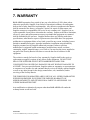
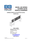
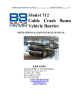
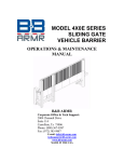
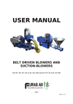
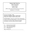
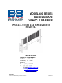
MODEL 400 SERIES SLIDING GATE VEHICLE BARRIER INSTALLATION AND OPERATIONS MANUAL B&B ARMR Corporate/Tech Support: 2009 Chenault Drive Carrollton, TX 75006 Suite 114 Phone: (800) 367-0387 Fax: (972) 385-9887 E-mail: [email protected] [email protected] www.bb-armr.com MADE IN THE USA B&B ARMR A Division of B&B Roadway and Security Solutions 04X0 Rev F3 Installation and Operations Manual — Model 400 Series TABLE OF CONTENTS iv Your safety is extremely important to us. If you have any questions or are in doubt about any aspect of the equipment, please contact us. INTRODUCTION Welcome! Congratulations on your purchase of a B&B ARMR vehicle barrier. In addition to providing detailed operating instructions, this manual describes how to install, maintain, and troubleshoot your vehicle barrier. If you require additional assistance with any aspect of your vehicle barrier's installation or operation, please contact us. With years of experience in all aspects of perimeter security and related disciplines, our products are used throughout the world to control access and to protect people, equipment, and facilities. We offer a broad range of vehicle barrier and related security services: Turnkey installations Routine barrier preventative maintenance or emergency repairs (including work on non-B&B ARMR products) Spare or replacement parts Custom designs or special installations Equipment upgrades (modernize your old equipment with state-of-the-art hydraulics and control systems) Ancillary security equipment such as security guard enclosures, card readers, security lighting, and many other security related products. Technical support via telephone and possible on site support with advanced scheduling. Safety Your safety is important to us. If you have any questions or are in doubt about any aspect of the equipment, please contact us. While B&B ARMR does not assume responsibility for injury to persons or property during installation, operation, or maintenance, we can provide verbal guidance, additional written instructions, or the services of a factory engineer. We're here to help you operate your vehicle barrier safely and effectively. As the user, you are responsible for correct and safe installation, operation, and maintenance of this equipment. Users must follow the specific instructions and safety precautions located in this manual. In addition they must: B&B ARMR A Division of B&B Roadway and Security Solutions 04X0 Rev F3 Installation and Operations Manual — Model 400 Series TABLE OF CONTENTS Be aware of and follow the safety standards of the Occupational Safety and Health Administration (OSHA), as well as other applicable federal, state, and local safety regulations and industry standards and procedures. For installation outside the United States, users must also follow applicable international, regional, and local safety standards. Engage only trained and experienced staff to install, operate, and maintain the equipment. Ensure that all repairs are performed correctly, using properly trained staff and the right tools and equipment. How to Contact Us If you have any questions or experience any problems with your vehicle barrier—or if we can help you with any other facility security issues—please contact us directly at: Corporate/Tech Support: B&B ARMR 2009 Chenault Drive Suite 114 Carrollton, TX 75006 USA Telephone: (972) 385-7899 Toll Free: (800) 367-0387 Fax: (972) 385-9887 E-mail: [email protected] [email protected] System Installation Record To assist in documenting the products installed in your system, please take a minute to record the following reference information. This information can be located on the blue B&B ARMR model number plate located on the product in the cylinder access area. Additional columns are added for your convenience in documenting other components in the system. Site: Job #: Date: Serial Number: Model Number: Voltage: Phase: B&B ARMR A Division of B&B Roadway and Security Solutions 04X0 Rev F3 v Installation and Operations Manual — Model 400 Series TABLE OF CONTENTS Table of Contents INTRODUCTION ......................................................................................................................................... iv Welcome! .................................................................................................................................................iv Safety ........................................................................................................................................................iv How to Contact Us ................................................................................................................................... v System Installation Record ..................................................................................................................... v 1. ORIENTATION ....................................................................................................................................... 7 1.1 Overview...................................................................................................................................... 7 1.2 Options .......................................................................................................................................12 1.3 Specifications .............................................................................................................................12 2. INSTALLATION .....................................................................................................................................13 2.1 Introduction ................................................................................................................................13 2.2 Preliminary Considerations .......................................................................................................13 2.3 Typical Installation of the Motor and Receiver Stanchions .......................................................14 2.4 Installing the Gate and Motor Components ...............................................................................16 2.5 Hydraulic Unit Installation ........................................................................................................18 2.6 Control System Installation ........................................................................................................19 3. OPERATION ...........................................................................................................................................21 3.1 Preliminary Steps .......................................................................................................................21 3.2 Initial Operation .........................................................................................................................21 3.3 Typical Operation.......................................................................................................................24 3.4 Barrier Operation During a Power Outage ...............................................................................25 4. MAINTENANCE .....................................................................................................................................26 4.1 Introduction ................................................................................................................................26 4.2 Monthly Inspections ...................................................................................................................27 4.3 Six-Month Inspections ................................................................................................................27 4.4 Hydraulic Oil Changing Procedure ...........................................................................................28 5. TROUBLESHOOTING ...........................................................................................................................29 6. ENGINEERING DRAWINGS .................................................................................................................31 7. WARRANTY ............................................................................................................................................38 8. EQUIPMENT MAINTENANCE LOG FORM .......................................................................................39 B&B ARMR A Division of B&B Roadway and Security Solutions 04X0 Rev F3 vi Installation and Operations Manual — Model 400 Series MAINTENANCE 7 1. ORIENTATION 1.1 Overview This manual addresses B&B ARMR Model 400 Series sliding cantilever gate vehicle barriers. The 400 Series barriers have high stopping power, and are designed to stop and disable a vehicle that tries to breach them. They are one in a series of anti-terrorism vehicle barrier designs manufactured by B&B ARMR. There are currently several models in the 400 Series: Model 400, Model 400A, Model 450, and Model 450A . The general descriptions of these basic models are as follows: Model 400—a sliding cantilevered crash gate rated to stop a 15,000-pound vehicle traveling at 30 miles per hour. Model 400A—a sliding cantilevered crash beam rated to stop a 15,000-pound vehicle traveling at 30 miles per hour. Model 450—a sliding cantilevered crash gate similar to the Model 400 but with a higher stopping power, the barrier is rated to stop a 15,000-pound vehicle traveling at 50 miles per hour. Model 450A—a sliding cantilevered crash beam rated to stop a 15,000-pound vehicle traveling at 50 miles per hour. Figure 1-1 will orient you to the three basic components of a 400 series vehicle barrier. 1. Gate Leaf (consisting of the pickets, the skirt, and the beam) 2. Motor Stanchion 3. Receiver Stanchion The sub-sections below briefly describe each of the components, and additional details are provided in other sections of this manual. B&B ARMR A Division of B&B Roadway and Security Solutions 04X0 Rev F3 Installation and Operations Manual — Model 400 Series MAINTENANCE 8 1.1.1 Gate Leaf The gate leaf (often just called the gate) consists of three parts: the pickets, the skirt, and the beam. The pickets are typically 1" square steel tubes spaced on 2.5" centers. The skirt is steel plate unless configured differently by customer. The pickets and skirt are usually assembled so that they are anti-climb, meaning there are no protrusions to serve as toeholds on the vehicle-approach side of the gate leaf. The standard gate height is 108 inches (9 feet or 2.75 meters) above grade. The standard opening when the gate leaf is fully retracted is 144 inches (12 feet or 3.66 meters). This is the space through which a vehicle will pass, and corresponds to the standard width of a traffic lane. Figure 1-1: Basic Components of a 400 Series Gate* Gate Leaf - Pickets - Beam - Skirt Receiver Stanchion Motor Stanchion * This figure is for illustration only. It shows the back (non-impact) side of an unpainted 400 series vehicle barrier undergoing testing. An as-shipped unit would be fully painted and would have other finish features not shown here. The beam part of the gate leaf is a massive steel I-beam. It provides the heavy-duty structure that stops the impacting vehicle. The stopping power is not from the beam alone, but from the manner in which the stanchions' heavy steel tubes transfer the vehicle's energy from the beam to the foundation. B&B ARMR A Division of B&B Roadway and Security Solutions 04X0 Rev F3 Installation and Operations Manual — Model 400 Series MAINTENANCE 9 While the pickets and skirt do not serve as principal structural elements, they do provide an important protective function. The height of the gate and its strength are designed to intercept and stop the attacking vehicle's load if the force of the impact launches it forward. 1.1.2 Motor Stanchion (and Associated Hydraulic and Control Unit) The motor stanchion—which is embedded in a concrete foundation—supports the gate during opening and closing. It houses the hydraulically driven motor that opens and closes the gate (gate leaf) and also the roller wheels upon which the gate rolls as it moves. During vehicle impact, its heavy steel tubes transfer the impact loads to the foundation. The Model 400 Series vehicle barrier operates from a complete, self-contained hydraulic and control unit housed in a sealed enclosure with locking doors mounted nearby. For information on the specific hydraulic unit mated with this gate, please refer to the associated Operation and Maintenance manual provided separately. The hydraulic unit is designed to operate for long periods with very little maintenance. It contains the hydraulic reservoir (which is not pressurized), hydraulic pump, and all of the required valves, manifolds, and flow control devices. An electric motor operates the gear-type hydraulic pump, which operates by a system pressure switch independent from the gate signal command. The hydraulic oil from the pump is drawn through a filter and into a manifold that distributes to an accumulator, then directional flow control valve. The directional control valves are energized from the PLC and control circuits to allow hydraulic oil to flow through flow control valves and out to the charlynn motor. The flow control valve monitors the gate speed. The operating logic controls the valves to ensure the correct gate position based on input controls from any set of dry contacts, such as limit switches and safety devices. These components are sized so that the gate will open or close at about one foot per second (one meter per 3 seconds). The opening/closing speed can be varied—within limits—by adjusting hydraulic flow control valves, as described later in this manual. The hydraulic pumping unit also houses the electric pump drive motor and control circuitry. The motor is typically a three horsepower, 208 / 240-480 volt, three-phase motor (refer to the associated manual for variances). An overload circuit protects the motor in the event of power fluctuations. During a power failure the gate can be operated from a hand pump, and it can also be opened and closed manually. The hydraulic and control unit is typically mounted B&B ARMR A Division of B&B Roadway and Security Solutions 04X0 Rev F3 Installation and Operations Manual — Model 400 Series MAINTENANCE 10 on a concrete pad close to the motor stanchion. Conduits connecting the unit and motor stanchion carry the hydraulic lines and electrical control cables. The unit also houses the gate control circuitry, the main components of which are the PLC (programmable logic controller) that is programmed with the gate's operating logic, the motor starter, and the motor overload protector. The control circuit is 120-volt, single-phase with 24-volt dc input. The outputs are 24-volt dc and 120-volt ac and some are customer defined for dry contacts. The unit has a built-in 120-volt convenience outlet (the customer supplies power and wiring to the box), and a master switch turns off all the power to the unit for maintenance and repairs. A disconnect is required for the 208-volt coming into the unit, and should be located close by. The key components of the motor stanchion are shown in Figure 1-2. Figure 1-2: Model 400 Series Motor Stanchion Roller Wheel Limit Switch Mount Conduit B&B ARMR A Division of B&B Roadway and Security Solutions 04X0 Rev F3 Installation and Operations Manual — Model 400 Series MAINTENANCE 11 1.1.3 Receiver Stanchion The receiver stanchion—which is embedded in a concrete foundation—captures (and locks in model 450) the end of the gate in place when the gate is fully closed. During vehicle impact, its heavy steel tubes transfer the impact loads to the foundation. Because of its relatively small size compared to the motor stanchion, it has additional reinforcements (gussets, stabilizer beams, and braces). Figure 1-3 shows the key components of the receiver stanchion. The 450 gates have a pair of two inch thick, stainless steel pins that are hydraulically raised and locked in place. A pair of proximity switches monitors the location of the pins that locks the gate from moving until they are in the full-up position. Three conduits are needed for the 450 receiver stanchion from the HPU, one for the hydraulic lines and two for control wires. The control wire is 120-volts for the IR beam and 24-volt dc for the proximity switches. Figure 1-3: Model 400 Series Receiver Stanchion B&B ARMR A Division of B&B Roadway and Security Solutions 04X0 Rev F3 Installation and Operations Manual — Model 400 Series MAINTENANCE 12 1.2 Options The Model 400 Series vehicle barriers are available with a broad array of options, as listed below. Consult your purchase order or other ordering documentation to determine whether your unit has the optional equipment. A wooden traffic control gate arm to warn the vehicle operator. This arm is positioned in front of the gate and does not rise until the gate is fully open, and it closes before the gate starts to close. Red/amber traffic lights. The light remains red if the gate is in any position except fully open. In-ground loop detector to detect the presence of a vehicle and prevent accidental closing of the gate onto the vehicle. Infrared safety beams to detect pedestrian traffic or as an additional vehicle sensing device. Keypads, card readers, or other vehicle access control devices. Heater and/or cooling fan for the hydraulic pumping unit. Heaters for the motor stanchion's hydraulic motor and for the roller wheels (for extreme winter conditions). 1.3 Specifications Key specifications for the Model 400 Series vehicle barriers are as follows. Certified vehicle-stopping power as summarized in the table below. Barrier Model Vehicle Weight Vehicle Speed U.S. Department of State Rating* 400 & 400A 15,000 pounds (~6,800 kg) 30 mph (~48 kph) K4 450 & 450A 15,000 pounds (~6,800 kg) 50 mph (~80 kph) K12 * If you are unfamiliar with the rating system nomenclature, contact B&B ARMR for additional information. Design operating frequency is 45 open and close cycles per hour. Design operating temperature range is 20°F – 100°F (Y°C – Y°C). B&B ARMR A Division of B&B Roadway and Security Solutions 04X0 Rev F3 Installation and Operations Manual — Model 400 Series MAINTENANCE 13 2. INSTALLATION 2.1 Introduction We designed the Model 400 Series vehicle barriers for quick and easy installation. However, every site is different and each 400 series will vary due to the choice of options or special design features. Accordingly, the instructions below may have to be varied slightly for your particular installation. If you need help, or are unclear about any of these instructions, please contact B&B ARMR for assistance. Your safety is extremely important to us. Be sure to follow the specific instructions presented below. You are responsible for the correct and safe installation, operation, and maintenance of this equipment. 2.2 Preliminary Considerations Before beginning site excavation and barrier installation, note the following important considerations. Inspect the site and verify there are no underground utilities or overhead wires or obstructions in the excavation area. If possible, locate the installation away from routine foot traffic to reduce the chance for pedestrian injury from the barrier's moving gate. Make sure that there is adequate free area adjacent to the motor stanchion's installation location so that the vehicle barrier gate can be slid onto the stanchion after the stanchion is cemented in place. Locate the HPU within twenty feet of the wheel stanchion. If the pump needs to be further away from the stanchion, please contact B&B ARMR. B&B ARMR A Division of B&B Roadway and Security Solutions 04X0 Rev F3 Installation and Operations Manual — Model 400 Series MAINTENANCE 14 2.3 Typical Installation of the Motor and Receiver Stanchions Perform the following steps to install the motor and receiver stanchions.(Always refer to your submittal for your specifications.) 2.3.1 Excavate the holes for the stanchions as shown in the Foundation Drawings supplied in your submittal. (See generic drawings in the drawings section). Place the stanchions in the excavation holes. 2.3.2 Install the axles for the roller wheels in the appropriate holes in the stanchions and tighten the setscrews against the flats on the axles. Tighten the setscrews securely, and use a locking compound on the setscrews threads if available. Use care when installing the axles, as they serve as the critical measuring point for final installation. 2.3.3 The tops of the axles must be 31-¾ inches above the roadbed height at the roadbed's highest point (If wheels are factory installed make sure they are 35-¾ inches above the roadbed). Adjust the stanchion's position in the excavation to bring the axles to the correct height. Use a transit to level all four points (the top of the end of each axle) and make any final adjustments in the positions of the stanchions so that the transit is reading within 1/32nd of an inch at each of the four points. It is CRITICAL THAT THE SHAFTS ARE PERFECTLY LEVEL for the gate to function properly. Verify also that the stanchions are plumb and level. 2.3.4 Place a partial pour of concrete into the excavation holes to lock the stanchions in place. Use the transit to verify the stanchions remain level and plumb. 2.3.5 Rough in the conduits. All conduits, fittings, sweeps, and couplings must be electrical grade (gray color); do not use plumbing type (white color). All conduits are run to the hydraulic pump unit. Accordingly, run all the conduits for your installation to the location where the hydraulic unit's concrete pad will be located. Run the conduits together and be sure the conduits are long enough to extend above the anticipated height of the hydraulic unit's pad. (See section 2.5, Hydraulic Unit Installation, for additional information.) 2.3.6 Make the final concrete pour, again making sure the axle height does not change and remain level and plumb. Remove any concrete that might have splattered inside the exposed conduits. 2.3.7 After the concrete has set, install the roller wheels, collars and nuts onto the axles. Place two collars (spacers) on each side of the shaft, then the wheel, then another collar, and finally the nut. Adjust the wheels and axle nuts so there is no side play in the wheels, but yet they can still be turned easily by hand. Tighten set screw on the nut. Grease the wheel bearings using the B&B ARMR A Division of B&B Roadway and Security Solutions 04X0 Rev F3 Installation and Operations Manual — Model 400 Series MAINTENANCE 15 grease fittings. The wheels may be pre-greased. Be careful not to overgrease the bearings; make sure the grease does not leak out of the sides of the bearings. 2.3.8 Install the four guide wheels into the guide wheel receivers on the wheel stanchion. Leave the bolts fully backed off to allow the guide wheels to insert completely into the receivers. Figure 2.3 – Interior View of Motor Stanchion B&B ARMR A Division of B&B Roadway and Security Solutions 04X0 Rev F3 Installation and Operations Manual — Model 400 Series MAINTENANCE 16 2.4 Installing the Gate and Motor Components Perform the following steps to install the gate (gate leaf), motor, and limit switches on the motor stanchion. 2.4.1 Lift the gate assembly using a crane or forklift. Guide the gate onto the first set of roller wheels, with the wheels fitting between the I-beam and the channel. Push the gate onto the second set of roller wheels. 2.4.2 Move the gate by hand to the halfway position. Install the stop plates onto the ends of the gate. 2.4.3 Attempt to slide the gate through about ⅔ of its travel. If the gate binds, adjust the roller wheels to eliminate the binding. 2.4.4 Mount the motor and gear assembly. Mount the motor on the wheel post closest to the roadway opening, and on the side between the two single posts. Leave the motor mount in the down position with the bolts slightly loose until the motor rotation and limit switches have been tested. 2.4.5 Mount the limit switches. They are generally mounted on the wheel post located on the barrier's run-out side (see figures 2.4.5-a, and 2.4.5-b). 2.4.6 Bolt the limit switch ramps (these are 2-foot/.66-meter long sections of electrical rack mounting) so they engage the limit switches' lever arms. The ramps must be located so they engage the switches before the gate reaches the desired spot, to allow for drift. The weight of the gate will allow the gate to coast even after the limit switches are activated. Plan for the gate to travel between 4 to 6 inches after the limit switch is activated. The ramps are long to ensure the gate will not coast so far when the gate comes to a stop, that the switches' lever arms become disengaged. B&B ARMR A Division of B&B Roadway and Security Solutions 04X0 Rev F3 Installation and Operations Manual — Model 400 Series MAINTENANCE 17 Figure 1 Limit Switch Mounting 2.4.7 Bolt the limit switch plates so they engage the limit switches' lever arms. The plate must be located so that both limit switches are hit in the correct sequence. The first limit switch tells the controller to slow the gate down. The second limit tells the controller to stop the gate. 2.4.8 Grease or cosmoline needs to be added to the rack, pinion and wheel areas to prevent oxidation. This should be checked and touched up during the monthly maintenance as needed. B&B ARMR A Division of B&B Roadway and Security Solutions 04X0 Rev F3 Installation and Operations Manual — Model 400 Series MAINTENANCE 18 2.5 Hydraulic Unit Installation Refer to separate manual for information on the specific model provide. 2.5.1 Typically, the Model 400 series hydraulic unit is mounted on a concrete pad. Generally, the hydraulic, electrical power, and control conduits will be run together, and all will turn up out of the concrete pad to attach to the hydraulic unit. Additional conduits may be required for traffic lights, loop detectors, and other options. Contact B&B ARMR if you are unclear about the conduit requirements for your installation. 2.5.2 Place the hydraulic unit on the pad over the exposed conduits and bolt the unit in place. (The feet on the unit will accept standard concrete anchors.) If you mount the unit to an intermediate steel structure, make sure that structure is securely fastened to the pad. 2.5.3 Terminate the electrical power and control conduits in the electrical box and the hydraulic hose conduit to the hydraulic side of the HPU. The hydraulic conduit should be cut flush with the concrete pad. This will allow the hydraulic hose to move slightly when pressure is applied without rubbing against any sharp edges on the conduit. 2.5.4 Install the hose by pulling it into the conduit, making sure to protect the hose from any sharp edges. When you cut the hose to length do not cut it too short, as the hose will shrink in length when under pressure. 2.5.5 Connect the hoses to the fittings located on the manifold. The two fittings on the left side of the manifold operate the gate, while the set on the right operate the locking pin cylinder (model 450 & 450A only) 2.5.6 The hydraulic unit's oil tank holds 30 gallons. Approved hydraulic oil must be added by removing the tank lid and pouring into the tank. The tank should be filled until the oil is half way up the sight glass. (See the Maintenance section for oil specifications and additional details.) You may see small amounts of oil in the unit when it arrives. This is residue from factory testing prior to shipment B&B ARMR A Division of B&B Roadway and Security Solutions 04X0 Rev F3 Installation and Operations Manual — Model 400 Series MAINTENANCE 19 2.5.5 Connect the hoses to the motor and also the locking pin cylinder (450 & 450A only) before the system is turned on. 2.6 Control System Installation Refer to the associated hydraulic pumping unit (HPU) manual for further clarification of the following information ad any references later to the (HPU). Install three-phase power to the lower right corner of the electrical box using the terminals marked L1, L2, L3, Neutral, and Ground. All devices that require ac power (such as loop detector, traffic lights, and infrared beams) can get 120-volt ac from the left side of the electrical box. Turning off the switch next to the convenience outlet disconnects all of the control power. Most other wiring is low-voltage (24-volt dc). Terminate all low-voltage inputs on the red terminal blocks at the bottom of the electrical box. Wire all switching devices (gate open, gate close, limit switches, and so on) so that each device gets 24-volt dc power from the left side of the I terminal blocks. Attach each device's input termination point wire to the appropriate I terminal block (I0, I1, I2, etc.) and the device's output termination point wire to the appropriate Q terminal block (Q0, Q1, Q2, etc.). A summary of key control wiring terminations is as follows. Traffic Lights (120-volt ac) Common to 120-volt neutral Red light to TLR (upper right) Amber light to TLG (upper right) Panel Indicator Lights (24-volt dc) Common to 24-volt dc negative Red to PLR (upper right) Green to PLG (upper right) Open Button Button to open gate – Normally Open Button common to I0 Button point to 24-volt dc+ B&B ARMR A Division of B&B Roadway and Security Solutions 04X0 Rev F3 Installation and Operations Manual — Model 400 Series MAINTENANCE 20 Close Button Button to close gate – Normally Open Button common to I1 Button point to 24-volt dc+ Locking Pin Open Limit Switch Jumper required for non 450 gates Switch common to I2 Switch point to 24-volt dc+ Safety Stop Jumper Jumper installed makes gate stop instead of open when a safety device is detected. Jump 24-volt dc+ to I3 Gate Close Limit Switch Switch must be wired for the gate to work Switch common to I4 Switch point to 24-volt dc+ Gate Open Limit Switch Switch must be wired for the gate to work Switch common to I5 Switch point to 24-volt dc+ Safety Devices Switch common to I6 Switch point to 24-volt dc+ Stop Button Button to stop gate – Normally Closed Button common to I7 Button point to 24-volt dc+ Locking Pin Close Limit Switch Jumper required for non 450 gates Switch common to I10 Switch point to 24-volt dc+ Emergency Close Button Closes gate regardless of Safety Devices Button common to I11 Button point to 24-volt dc+ Loop Detector – One loop detector and harness come pre-wired for use as a safety. Two loops can be wired in series and connected to inputs #7 and #8 on the loop detector harness. If you wish to use a loop as a free exit, contact B&B ARMR for prices or wiring information. B&B ARMR A Division of B&B Roadway and Security Solutions 04X0 Rev F3 Installation and Operations Manual — Model 400 Series MAINTENANCE 21 3. OPERATION 3.1 Preliminary Steps Before operating the Model 400 Series vehicle barrier, go through the checklist below and verify that each of these steps has been completed. For your safety, complete each of these steps before operating the barrier! The master power switch on the control circuit box is turned off. All traffic and pedestrians are clear of the barrier. The hydraulic pump unit is filled with oil and the oil level is correct. The gate is mounted to the stanchions and does not bind when moved manually. The roller wheel axles are securely mounted and the setscrews are tight. There is no side play on the roller wheels. The wheels have been greased The guide wheels have been adjusted so that they extend further than the main wheels (to avoid binding). Make sure the guide wheels on each end of the stanchion are both not tight to the gate. There should be about ¼ inch clearance between the sets of guide wheels and the ends of the gate. The spur gear of the motor is not engaged to the gear rack of the gate. The limit switch ramps have been installed to stop the gate in the proper location and will not allow it to run off the track. The limit switches must be tested prior to applying the motor spur gear to the gear rack! 3.2 Initial Operation Perform the following steps the first time you operate the vehicle barrier, and also after replacing the hydraulic oil or after any major repairs. 3.2.1 Turn on the power at the master power switch located nearby the HPU. With a volt-meter, check the incoming voltage to make sure source power is correct. If correct, turn on power switch in the HPU. Have someone remain at the power switch during the initial operation in case there is a malfunction and the unit must be shut down. B&B ARMR A Division of B&B Roadway and Security Solutions 04X0 Rev F3 Installation and Operations Manual — Model 400 Series MAINTENANCE 22 3.2.2 Close the pressure relief valve on the back side of the manifold. Turn the valve clockwise to close it. Pressure will not build up if the valve is open. 3.2.3 Make sure the pump builds up pressure and stops somewhere between 1500psi and 1850psi. If the pump does not immediately come on, check the motor overload circuit and press start. Check that the motor overload circuit dial is set to between 9 and 10 amps. If the pump motor is running, but does not stop when the pump reaches 1850, adjust the pressure switch connected to the back of the pressure gauge. Turn the pressure switch clockwise to increases the pressure that the pump builds up to and counter-clockwise to decrease. The pressure that the switch activates the pump to come back on is based on a percentage of the level the switch is set to turn off. 3.2.4 Check the control and safety inputs of the system. • Depress the OPEN limit switch and verify that I5 lights up on the PLC. • Depress the CLOSE limit switch and verify that I4 lights up on the PLC. • Activate any safety devices (IR Beam, safety loops, safety edge, etc) and verify that I6 lights up on the PLC. 3.2.5 Model 450 & 450A only: Manually shift the directional control valve to raise and lower the locking pin cylinder. The directional control valve for the locking cylinder is on the right hand side of the manifold block as you look into the pump. Push in one side of the valve to lower the pins and verify that I3 is lit on the PLC. Push in the other side of the same valve and raise the pins and verify that I2 is lit on the PLC. If either of these inputs are not coming on, adjust the proximity switches so they read the position of the locking pins. Repeat manual raise and lower several times to ensure the proximity switches will read every time. Leave the pins in the UP position. Check for hydraulic leaks B&B ARMR A Division of B&B Roadway and Security Solutions 04X0 Rev F3 Installation and Operations Manual — Model 400 Series 3.2.6 MAINTENANCE 23 Test the rotation of the motor and the open and close buttons. Give the gate a CLOSE command from the control panel button. Verify that I2 lights up on the PLC and also Q21. Your spur gear should be rotating now. Make sure that it will be turning in the proper direction to CLOSE the gate. If the rotation is wrong, reverse the hydraulic hoses at the motor. Test again until the motor is rotating properly. 3.2.7 Test the CLOSE operation. Give the gate a CLOSE command (I2) and watch the rotation of the motor. With the motor running, hold down the CLOSE limit switch and continue to hold. The motor should slow down for .5 seconds and then stop, Q3 will come on for this short duration to activate the slow down valve. Adjust the flow control valve to make sure the gear is not rotating too slow or too fast. Also make sure that the spur gear runs slower when Q3 is activated (adjust the slow speed with the flow control valve at the bottom of the HPU. The locking pins should then lower (Q5 will activate the directional control valve automatically). Go to next step even if the pins do not lower. 3.2.8 Test the OPEN operation. Give the gate an OPEN command (I1). The locking pins should rise. (If they lower during this operation and rose during the CLOSE operation, switch the hoses to the cylinder.) After the pins rise and energize input I3, the spur gear will be rotating. Make sure the direction is correct. With the spur gear rotating, hold down the OPEN limit switch. Make sure that the gear stops rotating when the limit switch is activated. Adjust the flow control valve for the OPEN speed. 3.2.9 Make sure the limit switch ramps are in the correct position so the gate stops at the correct open and closed positions. 3.2.10 Set the motor mount. The service life of the gate's gear system depends on the gear spacing. Once the gate is installed, inspect the pinion gear-to-rack spacing. There should be a space of 1/16 to ⅛ inches between the top of the pinion gear and the root (valley) of the rack. This gap minimizes the impact forces and gear wear when the gate coasts momentarily during a direction change. Adjust the gear spacing accordingly while the beam is centered on the stanchion. 3.2.11 Give the gate an open command (I1). Make sure the gate stops smoothly when the limit switch is activated. Once the gate is open, I5 will start an output which will activate a B&B ARMR A Division of B&B Roadway and Security Solutions 04X0 Rev F3 Installation and Operations Manual — Model 400 Series MAINTENANCE 24 timer to automatically close the gate. If you do not want the gate to automatically close disconnect the wire to the timer. If you use this feature, adjust the timer. The dial closer to min, minimizes the time it will take to give the close command. If you disconnect this feature go to the next step. 3.2.12 Give the gate a CLOSE command (I1). Make sure the gate stops smoothly when the limit switch is activated. Once the gate is closed, the locking pins will drop until they activate the Locking Pin Down Limit Switch on 450 Models 3.2.13 You can adjust the gate's open and close speed by turning the flow control valves located in the hydraulic pumping unit. The flow control is located under the directional control valve. The knurled knobs on the valves should be turned with an allan wrench clockwise to slow the gate and counterclockwise to increase the gate's speed. The nominal time for the gate to open and close one foot per second. A standard 12-foot (3.66-meter) gate should take 12 – 15 seconds to open or close. Safety Note: The Model 400 Series safety devices are designed to stop a closing gate and reverse the motion. Verify that the gate's speed is slow enough that it will stop moving immediately when any safety device is activated. 3.3 Typical Operation The system receives an OPEN input signal, typically from the control panel open button, a card reader or a loop detector. Upon receiving the signal, the PLC activates the locking pin directional control valve which open the locking pin mechanism (On 450 & 450A gates, all other gates will jumper a signal to I3 to simulate a pin in the up position). Then the gear motor directional control valve shifts and sends hydraulic fluid to the motor which turns the spur gear and moves the gate in the open direction. The gate continues to move until the open limit switch is activated or until a 40 second internal timer times out and stops the gate. The gate should open within the 40 seconds, if it does not, check for mechanical binds or speed the gate up by use of the flow control valve. A safety device does not stop the gate from moving in the open position. If you wish to stop a gate whenever a safety device is activated, apply a jumper from 24-volt+ to I6. B&B ARMR A Division of B&B Roadway and Security Solutions 04X0 Rev F3 Installation and Operations Manual — Model 400 Series MAINTENANCE 25 The gate will send an output through Q7 to activate a timer that will automatically close the gate. If you do not want the gate to automatically close disconnect the wire to the timer or from Q7. The system receives a CLOSE input signal from the control panel close button or the timer. Upon receiving the signal, the PLC activates the gear motor directional control valve and sends hydraulic fluid to the motor which turns the spur gear and moves the gate in the close direction. The gate continues to move until the close limit switch is activated, a safety input is received or until a 40 second internal timer times out and stops the gate. When the limit switch activates, the locking pin directional control valve shifts the locking pin mechanism (On 450 & 450A gates, all other gates will jumper a signal to simulate a pin already in the down position). The gate should close within the 40 seconds, if it does not, check for mechanical binds or speed the gate up by use of the flow control valve. A safety device input (I6) will cause the gate to slow down, stop and reverse and open until it reaches the full open position. If you wish to stop a gate whenever a safety device is activated, apply a jumper from 24-volt+ to I6 (Safety STOP -not close- jumper). To bypass the safety features in case of emergency – close gate with an input to I11 (Emergency Close – safety bypass). A separate button with a secured, flip top should be installed for this type of activation. The gate still closes at the same speed. * Note: After using the emergency close function the gate will not respond to new commands until (I10) the emergency reset function is activated. 3.4 Barrier Operation During a Power Outage You can open and close the gate manually during a power outage as follows. 3.4.1 When the HPU loses power, all control inputs and outputs are interrupted. The system does not receive any signals, nor does it send any. 3.4.2 The HPU does retain hydraulic pressure in the accumulator which can be used to move the gate. • Manually shift the locking pin-directional control valve to raise the locking pins (only if operating a 450 or 450A gate to the open position) B&B ARMR A Division of B&B Roadway and Security Solutions 04X0 Rev F3 Installation and Operations Manual — Model 400 Series MAINTENANCE 26 • Manually depress the gate-directional control valve in the desired direction you wish the gate to travel (the exact side of the valve to press for open and close is different for each gate. You may wish to label which side of the valve moves the gate in which direction at time of installation.) 3.4.3 Depending on the size of the gate, you should be able to cycle the gate open and closed one time with the pressure in the accumulator. The motor will not be able to move the gate when the pressure reaches about 600psi. To increase the pressure manually, drive the hand pump back and forth until the pressure reaches between 800 and 1000psi. Repeat step 3.4.2. 4. MAINTENANCE Do not attempt repairs unless you are trained and qualified. This vehicle barrier can cause equipment damage and severe injury if it is operated or maintained improperly. 4.1 Introduction The Model 400 Series vehicle barriers are designed to be largely maintenance free. As with any complex electromechanical device however, they must be regularly inspected to ensure they are operating correctly. We recommend a simple monthly visual inspection and a more thorough biannual inspection as described below. Also described below is the procedure for draining and changing the hydraulic oil, should this ever be required. Remember, you may contact B&B ARMR for assistance with inspections, maintenance, or repairs. Component damage is likely if a vehicle strikes the barrier. If this occurs, contact B&B ARMR. We will help you assess the damage and make sure there is no hidden damage that will compromise safety or effectiveness. We will help you determine which components should be replaced, and will provide guidance on the repairs. B&B ARMR A Division of B&B Roadway and Security Solutions 04X0 Rev F3 Installation and Operations Manual — Model 400 Series MAINTENANCE 27 4.2 Monthly Inspections We recommend you perform the following visual inspections monthly. 4.2.1 Open and close the gate and observe its motion. Verify the open/close time is within the normal range, which is one foot per second. 4.2.2 During the opening and closing cycle, verify the gate operates smoothly and does not bind. Adjust the guide wheels as necessary to eliminate binding. Also verify that the gate does not hit with excessive force when it contacts its full-open or full-closed positions. If necessary, adjust the gate's speed (see the instructions in section 3.2.12 in the Operation section of this manual). 4.2.3 Inspect the condition of the paint. If rust is present, wire brush and sand the area then paint with a primer and the matching color. 4.2.4 Inspect the motor for wear on the spur gear, and verify that the proper spacing is present between the spur gear and gear rack. Tighten bolts. 4.2.5 Verify limit and proximity switches are still in the proper position. Adjust and tighten if necessary. 450 & 450A Models have two additional proximity switches for the locking pin mechanism. 4.2.6 Inspect oil level through sight glass on tank. The oil should remain at the same level once the gate is operational (it is a closed hydraulic circuit). If the oil level has dropped, check for leaks in the HPU, the drive motor or the locking pin cylinder. Check the hoses for wear or abrasion. Relieve pressure from system before fixing leaks. Safety Note: If you replace a hydraulic hose you must make sure the pressure has been relieved before disconnecting the hose fittings or fix leaks. 4.3 Six-Month Inspections We recommend you perform the following inspections every six months. 4.3.1 Repeat the visual inspections in steps 4.2.1 through 4.2.6 above. 4.3.2 Turn the master power switch on the control circuit box to the OFF position. 4.3.3 Inspect guide wheels. Check for proper adjustment and wear on wheels or gate. Readjust if necessary. 4.3.4 Inspect roller wheels, grease fittings. Make sure oil seals (on side of wheels) are still tight and no grease is coming out the sides of them. Make sure that the wheels and nuts are still tight, and the wheels are turning freely. 4.3.5 Inspect the Hydraulic Pumping Unit for signs of oil leaks. Check all fittings for tightness. Add oil as necessary. We recommend using environmentally safe oil such as Mobil EAL 224. Change hydraulic oil filter. 4.3.6 Open the hydraulic oil tank and inspect the oil for dirt or water. If oil replacement is necessary, see section 4.4 below. 4.3.7 When the inspection is complete, turn the master power switch on the control circuit box to the ON position. B&B ARMR A Division of B&B Roadway and Security Solutions 04X0 Rev F3 Installation and Operations Manual — Model 400 Series MAINTENANCE 28 Safety Note: After any major repairs, repeat the Preliminary Steps (see section 3.1) and the Initial Operation sequence (see section 3.2) before returning the barrier to service. 4.4 Hydraulic Oil Changing Procedure Follow the steps below to drain and refill the oil tank. We recommend using environmentally safe oil such as Mobil EAL 224. Please refer to the HPU user manual for specific instructions relating to the HPU. 4.4.1 Remove the lid on the hydraulic reservoir in the HPU. 4.4.2 Remove the old, used oil and clean the tank thoroughly. In the bottom of the tank is a filter screen. Remove the screen and clean or replace if necessary. 4.4.3 Add new oil until the oil level is ½ the distance up the site glass on the HPU. Replace the lid on the HPU reservoir. Safety Note: After changing the hydraulic oil, repeat the Preliminary Steps (see section 3.1) and the Initial Operation sequence (see section 3.2) before returning the barrier to service. B&B ARMR A Division of B&B Roadway and Security Solutions 04X0 Rev F3 Installation and Operations Manual — Model 400 Series TROUBLESHOOTING 29 5. TROUBLESHOOTING The table below provides guidance on identifying and correcting issues with your Model 400 Series vehicle barrier. If you encounter problems that you cannot fix, contact B&B ARMR and we will gladly work with you to correct them. Model 400 Series Troubleshooting Guide Symptom Gate does not go open Gate does not go close HPU does not build up pressure, but is running B&B ARMR A Division of B&B Roadway and Security Solutions Actions 1. Check power 2. Check overload protector 3. Check pressure gauge 4. Manually open the gate by depressing the directional control valve to see if problem is mechanical or electrical. If mechanical, check for binding on the gate. If not: 5. Check PLC input 6. Check that safeties are clear 7. Check PLC output 8. Check push button operation 9. Check locking pin and proximity switch, gate will not open unless the pins are up and I3 is lit on the PLC 1. Check power 2. Check overload protector 3. Check pressure gauge 4. Manually close the gate by depressing the directional control valve to see if problem is mechanical or electrical. If mechanical, check for binding on the gate. If not: 5. Check PLC input 6. Check that safeties are clear 7. Check PLC output 8. Check push button operation 9. Check locking pin and proximity switch, gate will not open unless the pins are up and I3 is lit on the PLC 1. Check power 2. Close pressure relief valve 04X0 Rev F3 Installation and Operations Manual — Model 400 Series Symptom HPU pump will not turn on Gate makes noise during operation Hydraulic unit is excessively hot Gate moves too slowly TROUBLESHOOTING Actions 1. Check power 2. Check motor overload, press start 3. Check motor starter 4. Check low level switch 5. Check pressure switch 1. Check that roller wheel bearings are greased 2. Check that gate is not moving too fast 3. Check that the guide wheels are properly adjusted 4. Check that the spur gear is properly adjusted to the gear rack 1. Check that the pressure relief valve is closed (fully clockwise) 2. Check that the pressure switch is adjusted to shut the motor off before 1850psi 3. Check for correct voltages 1. Check for mechanical binds (guide wheels out of adjustment, debris under the wheels or on the inside of gate 2. Check flow control valve 1. Check proper limit switch operation Traffic indicator light does not change 2. Check bulbs Locking pins are moving but not giving signals up or down to I3 3. Check PLC outputs 1. Check the proximity switches at the locking pin mechanism B&B ARMR A Division of B&B Roadway and Security Solutions 04X0 Rev F3 30 Installation and Operations Manual — Model 400 Series TROUBLESHOOTING 6. ENGINEERING DRAWINGS The following engineering drawings are for reference only. For job specific drawings and details please refer to the Submittal Documentation specific to the job. For replacement components and parts breakdown, please contact B&B ARMR tech support. B&B ARMR A Division of B&B Roadway and Security Solutions 04X0 Rev F3 31 GENERIC 400 CANTILEVER SLIDING GATE 20' RIGHT HAND CLEAR OPENING 9' GATE HEIGHT B&B ARMR 2009 Chenault Dr. #114 Carrollton, Tx 75006 800-367-0387 Installation and Operations Manual — Model 400 Series B&B ARMR A Division of B&B Roadway and Security Solutions TROUBLESHOOTING 04X0 Rev F3 32 TROUBLESHOOTING 400 CRASH BEAM LEFT HAND CLEAR OPENING B&B ARMR 2009 Chenault Dr. #114 Carrollton, Tx 75006 800-367-0387 Installation and Operations Manual — Model 400 Series B&B ARMR A Division of B&B Roadway and Security Solutions 04X0 Rev F3 33 TROUBLESHOOTING 450A CANTILEVER SLIDING GATE 20' LEFT HAND CLEAR OPENING B&B ARMR 2009 Chenault Dr. #114 Carrollton, Tx 75006 800-367-0387 Installation and Operations Manual — Model 400 Series B&B ARMR A Division of B&B Roadway and Security Solutions 04X0 Rev F3 34 TROUBLESHOOTING 400/400A CANTILEVER SLIDING GATE CONDUIT LAYOUT B&B ARMR 2009 Chenault Dr, #114 Carrollton, Tx 75006 800-367-0387 Installation and Operations Manual — Model 400 Series B&B ARMR A Division of B&B Roadway and Security Solutions 04X0 Rev F3 35 TROUBLESHOOTING 450/450A CANTILEVER SLIDING GATE CONDUIT LAYOUT B&B ARMR 2009 Chenault Dr, #114 Carrollton, Tx 75006 800-367-0387 Installation and Operations Manual — Model 400 Series B&B ARMR A Division of B&B Roadway and Security Solutions 04X0 Rev F3 36 TROUBLESHOOTING 400 SERIES CANTILEVER SLIDING GATE FOUNDATIONS B&B ARMR 2009 Chenault Dr., #114 Carrollton, Tx 75006 800-367-0387 Installation and Operations Manual — Model 400 Series B&B ARMR A Division of B&B Roadway and Security Solutions 04X0 Rev F3 37 Installation and Operations Manual — Model 400 Series TROUBLESHOOTING 7. WARRANTY B&B-ARMR warranties for a period of one year, after delivery F.O.B. plant, unless otherwise specified by Supplier, from failure of operation in ordinary use and against defects due to faulty material or workmanship. Any defective equipment in the Barrier shall be returned to the factory, at Supplier’s option, for repair or replacement, and Supplier assumes no responsibility for service at any consumer site. Supplier is in no event responsible for any labor costs under the warranty. Subject to the above limitation, all service, parts, and replacements necessary to maintain the equipment as warranted shall be furnished by the end user. Supplier shall not have any liability under these specifications, other than for repair or replacement as described above for equipment malfunction or equipment failure of any kind, caused for any reason, including, but not limited to unauthorized repairs, improper installation, installation not performed by Supplier personnel, nor by Supplier authorized personnel, failure to perform manufacturer’s suggested routine maintenance, modifications, misuse, accident, catastrophe, neglect, natural disaster, act of God or if at any time the power supplied to any part of the Security Barrier falls short or exceeds the rate of tolerance for the equipment. The exclusive remedy for breach of any warranty by Supplier shall be the repair or replacement at supplier’s option, of any defects in the equipment. IN NO EVENT SHALL THE SUPPLIER OF SECURITY BARRIER BE LIABLE FOR CONSEQUENTIAL OR SPECIAL DAMAGES OR ANY KIND OF DAMAGES TO ANYONE. Except as provided herein, Supplier makes no warranties or representations to consumer or to anyone else and consumer hereby waives all liability against Supplier as well as any other person for the design, manufacture, sale, installation, and/or servicing of the Security Barrier. THE FOREGOING WARRANTIES ARE IN LIEU OF ALL OTHER WARRANTIES EXPRESS OR IMPLIED, INCLUDING THE IMPLIED WARRANTY OF MERCHANTABILITY AND FITNESS FOR A PARTICULAR PURPOSE. NO OTHER WARRANTIES EXIST. Any modification or alteration by anyone other than B&B-ARMR will render the warranty herein as null and void. B&B ARMR A Division of B&B Roadway and Security Solutions 04X0 Rev F3 38 Installation and Operations Manual — Model 400 Series TROUBLESHOOTING 39 8. EQUIPMENT MAINTENANCE LOG FORM Product Type:________________________ B&B ARMR 800-367-0387 Location:____________________________ [email protected] Jan Checklist Complete Yes No Feb Yes No Mar Yes No Apr Yes No May Yes No Jun Yes No Jul Yes No Aug Yes No Sep Yes No Oct Yes No Nov Yes No Year Yes No Date Date Performed By Performed By Checklist Complete Jan Yes No Feb Yes No Mar Yes No Apr Yes No May Yes No Jun Yes No Jul Yes No Aug Yes No Sep Yes No Oct Yes No Nov Yes No Year Yes No B&B ARMR A Division of B&B Roadway and Security Solutions Anomalies Notes Anomalies Notes 04X0 Rev F3