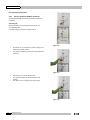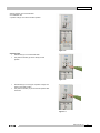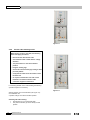
1
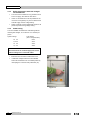
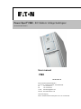
Power Xpert® FMX - IEC Medium Voltage Switchgear User manual 605.4016 G01 01 User manual FMX 605.4016 G01 01 Eaton Industries (Netherlands) B.V. P.O. box 23, 7550 AA Hengelo, The Netherlands tel: +31 74 246 91 11 fax: +31 74 246 44 44 e-mail: [email protected] internet: www.eatonelectric.com Service emergency: Eaton – Electrical Services & Systems: tel: +31 74 246 68 88 FMX Administrative data Issue number: G01 01 Date of issue: 01-02-2011 Translation of: 51350 2509 G01 001 Authorised by Job title: Product Manager Name: B. Ter Hedde Date: 01-02-2011 Initials: 2 605.4016 G01 01 FMX CONTENT 1. GENERAL ............................................................................................... 5 1.1 Introduction ........................................................................................................... 5 1.2 Explanation of used warnings .............................................................................. 5 1.3 Safety relating to medium-voltage installations .................................................. 5 1.4 Tools, aids and protection equipment ................................................................. 6 1.5 Product standards and guidelines used .............................................................. 6 1.6 Product information .............................................................................................. 7 2. FMX SYSTEM DESCRIPTION ................................................................ 9 2.1 FMX System description ....................................................................................... 9 2.2 Cross-section, single line diagram and list of functions .................................. 10 2.3 Technical specifications, general ....................................................................... 11 3. INSTALLING THE UNIT ........................................................................ 12 3.1 3.1.1 3.1.2 Environmental requirements .............................................................................. 12 Transport, assembly and storage conditions .......................................................... 12 Ambient conditions when the unit is in service ....................................................... 13 3.2 3.2.1 3.2.2 Installing the unit ................................................................................................ 14 Lifting .................................................................................................................... 14 Travelling .............................................................................................................. 15 3.3 3.3.1 3.3.2 3.3.3 3.3.4 Connecting the cables ........................................................................................ 15 Types of cables ..................................................................................................... 15 Cable assembly instructions .................................................................................. 15 Safety precautions with test voltages for the FMX-unit .......................................... 16 Cable testing ......................................................................................................... 16 3.4 Connection of station earthing ........................................................................... 18 3.5 Access to secondary compartment .................................................................... 18 3.6 Connection of secondary cables ........................................................................ 18 4. OPERATION .......................................................................................... 19 4.1 Explanation of the Control Panels ..................................................................... 19 4.2 4.2.1 4.2.2 Operation (electrical) .......................................................................................... 20 Service position ON/OFF switching ....................................................................... 20 Switch cable earthing on/off .................................................................................. 22 4.3 Manual operation ................................................................................................ 27 4.4 4.4.1 4.4.2 Interlocks ............................................................................................................. 29 Earth position interlocking ..................................................................................... 29 Locking of the 2-position change-over switch ........................................................ 30 4.5 4.5.1 Signals ................................................................................................................. 30 Voltage detectors .................................................................................................. 30 5. REMOTE SIGNALLING AND REMOTE CONTROL ............................. 31 5.1 Remote signalling ............................................................................................... 31 605.4016 G01 01 3 FMX 5.2 5.2.1 5.2.2 Remote control .................................................................................................... 31 Remote opening .................................................................................................... 31 Remote closing ..................................................................................................... 31 6. INSPECTION AND MAINTENANCE ..................................................... 32 6.1 Introduction ......................................................................................................... 32 6.2 6.2.1 6.2.2 6.2.3 6.2.4 Inspections .......................................................................................................... 32 Inspecting of cable connections ............................................................................ 32 Inspection of the enclosure ................................................................................... 32 Inspection of the operation of the circuit-breaker ................................................... 32 Inspection of the protection relay ........................................................................... 33 6.3 6.3.1 Decommissioning the unit .................................................................................. 33 Material processing after dismantling .................................................................... 33 7. ACCESSORIES ..................................................................................... 34 7.1 Supplied accessories .......................................................................................... 34 7.2 Available accessories and spare parts .............................................................. 34 APPENDIX 1 – VOLTAGE DETECTION ......................................................... 35 APPENDIX 2 – AVAILABLE ACCESSOIRES AND SPARE PARTS ............. 36 4 605.4016 G01 01 FMX 1. GENERAL 1.1 Introduction 1.3 Safety relating to medium-voltage installations WARNING Operations on medium-voltage installations can The user must have authority to perform switching operations, which means being qualified in accordance with locally applicable guidelines, government legislation and in-house company regulations with respect to the operation of medium-voltage installations. be life threatening if the necessary procedures are not observed. Legal and other regulations and documents pertaining to accident prevention, personal safety and environmental protection must be observed. Operations involving the repair of the switchgear unit are to Always take suitable precautions before working on a medium-voltage installation. All personnel involved in operations carried out on, with or near electrical installations require to have been instructed be carried out by or under the responsibility of Eaton Industries (Netherlands) B.V. Information with respect to these operations is, therefore, not included in this manual. on the safety requirements, safety rules and instructions applicable to the operation of the installation. Personnel must wear suitable clothing which fits the body closely. The person in charge of the operations must ensure that all 1.2 Explanation of used warnings requirements, regulations and instructions are complied with. The FMX unit has been designed to ensure that it exceeds applicable regulations. Furthermore, primary component enclosures are arc-resistant and interlocks The manual uses the following names and signs to highlight important (safety) information: have been fitted to prevent dangerous operations. WARNING This warning indicates that non-observance of the specified (safety) instructions COULD result in serious bodily injury or even death. NOTE This note provides the user with additional information. The user's attention is drawn to possible problems. Operations when the unit has been isolated Carrying out operations on an isolated system is subject to a number of essential requirements. 1. 2. 3. 4. switching off; complete isolation; protection from reactivation; checking whether the unit is dead; 5. provide short-circuit proof protective earthing and a visible take-over earth when needed. provide protection with respect to active components in the vicinity. 6. TIP Tips provide the user with suggestions and advice on how to make certain tasks easier or more convenient. Safe layout of the work area Ensure that access and escape routes are free at all times. Do not leave flammable materials in or near access and escape routes. Flammable materials must not be stored in areas which could be affected by arcs. In the event of a fire Never attempt to extinguish a fire on the switchgear unit before it is completely dead, this applies to both primary and secondary switchgear. Even if non-conducting extinguishing materials are used, electricity may pass through the extinguishing equipment. Never extinguish a fire on the unit with water. Prevent water from flowing into the unit. Keep well clear of the unit while the fire is being extinguished in the area around the unit. 605.4016 G01 01 5 FMX 1.4 Tools, aids and protection equipment Tools, aids and protection equipment must meet the requirements of national and international standards insofar as they are applicable. Drawings and documents Recent documents of the electrical installation must be available in order to gain sufficient understanding of the schematic layout of the switchgear unit. Warning signs If necessary, suitable warning signs shall be placed on the switchgear unit during operations to highlight possible hazards. The warning signs must comply with the applicable standards, insofar as they apply. Performing measurements safely on the unit Suitable and safe measuring equipment must be used for measuring safely on the unit. These instruments must be checked before and after use. The instruments must also be inspected periodically in accordance with the applicable regulations. 1.5 Product standards and guidelines used Switchgear General IEC Standard Common specifications for high-voltage switchgear and controlgear 62271-200 A.C. metal-enclosed switchgear and controlgear for rated voltages above 1 kV and up to and including 52 kV A.C. insulation-enclosed switchgear and controlgear for rated voltages above 1 kV and up to and including 38 kV 62271-201 Devices Title 62271-1 62271-100 High-voltage alternating-current circuit-breakers 62271-102 Alternating current disconnectors and earthing switches 50181 Degrees of protection 60529 Plug-in type bushings above 1kV up to 36kV and from 250A to 1.25kA for equipment other than liquid filled transformers Degrees of protection provided by enclosures (IP Code) Voltage detection 61243-5 Live working - Voltage detectors - Part 5: Voltage detecting systems (VDS) Transformers 60044-1 Instrument transformers - Part 1: Current transformers 60044-2 Instrument transformers - Part 2 : Inductive voltage transformers 60870-5 Telecontrol equipment and systems. Part 5: Transmission protocols 61850 Communications networks and systems in substations ISO 9001-2000 Quality ISO 14001 Environmental management Communication ISO Table 1: Current product standards used 6 605.4016 G01 01 FMX 1.6 Product information The panel nameplate includes: the switch type; The unit is equipped with nameplates on the bottom of the top-unit. The system nameplate includes: technical specifications; serial number and year of manufacture. Application outside the 'Normal Service Conditions' set out in IEC Please contact Eaton if the unit is used in an environment not in accordance with the 'Normal Service Conditions' in IEC 62271-1. Each panel is uniquely identifiable by its panel nameplates. They are located on the left inside wall in the cable connection compartment of each panel. Eaton Industries (Netherlands) B.V. Medium Voltage P.O. box 23, 7550 AA Hengelo, The Netherlands Powering Business worldwide M.V. SWITCHGEAR IEC 62271-200 system: FMX r1.0 Metal enclosed w.o. no.:xxxxxxx Serialno: xxxFMXxxxxxxxx Ur 24 kV Up Ir 2000 A Ik IAC AFL 125 kV 25 kA Ua technical specifications. Year of man.: 2010 Ud Ip 50 kV 63 kA fr 50 Hz tk 3s xxx VDC Main switching device: 25kA-1s Cable compartments: 25kA-1s Figure 1-1: Example of system nameplate CIRCUIT-BREAKER IEC 62271-100 CURRENT TRANSFORMER IEC 60044-1 type: Class: M2 E2 C2 type: Make: NVF18CA-2416 R1.0 Ur 24 kV Up 125 kV Ir 1600 A Isc 25 kA Ic 31.5 A CTS S1 – S2 tk EATON 75/5 A 3.0 s 5 VA Cl. 10P10 extd. 120% Operating sequence O-0.3s-CO-15s-CO For system information refer to nameplate Ip Figure 1-2: Example of panel nameplate for 63 A Ik 25 kA tk 1s Figure 1-3: Current transformer information plate circuit-breaker VOLTAGE TRANSFORMER IEC 60044-2 type: YH0-3 Make: A-N 10000/√3 a1-n 100/√3 7,5 V Cl. 0,2 Sth. 400VA da-d 100/3 30 VA Cl. 3P Sth. 100VA 12-28-75 kV Sadtem 1,9 Ur - 8h Figure 1-4: Voltage transformer Information plate 605.4016 G01 01 7 FMX Table 2: Explanation of nameplate data in accordance with IEC Variable Description Unit system System - r. Release - IEC IEC reference - type Type of switching device - serial no. Serial number - year of man. Year of manufacturing - w.o.no. Works order number - fr Rated frequency Hz Ik Rated short-time withstand current kA Ima Rated short-circuit making current kA Ip Rated peak withstand current kA Ir Rated normal current A Isc Rated short-circuit breaking current kA kA tk Rated duration of short-circuit s Ua Rated supply voltage of auxiliary circuits V Ud Rated short-duration power-frequency withstand voltage (1 minute) kV r.m.s. Up, Uw Rated lightning impulse withstand voltage (peak) kV Ur Rated voltage kV Ur.t Rated voltage factor and corresponding rated time Vs Isolation level Rated insulation level kV Class M, E, C Classification according to IEC - Operating sequence Rated operating sequence - VA Rated output VA CL Accuracy Class - IAC Internal Arc Classification - AFLR A= Authorized personnel only - F = Front side L = Lateral sides R = Rear side 8 605.4016 G01 01 FMX 2. FMX SYSTEM DESCRIPTION 2.1 FMX System description The FMX switchgear system is a system with circuitbreakers which can be available for applications up to 24kV. The system is fully metal-enclosed. A very compact and safe implementation is achieved using high-quality epoxy resin insulation. Electric field strengths are kept at low levels by using specially shaped single-pole insulation components, as a result of which the risk of an internal fault is kept to an absolute minimum. All live primary components of the unit and the main components of the drive mechanisms are housed in a closed enclosure. This prevents any dust, moisture and other environmental factors from affecting the proper operation of the system. The enclosure is also arc resistant and thus provides conditions of optimum safety for the operator. The cable compartments are also available in arc-proof configuration. Two basic panel versions are available: a vacuum circuit-breaker of 630, 800, 1250, 1600, 2000 A a sectionaliser panel with vacuum circuit-breakers of 1250, 1600, 2000 A Both versions can be supplied in any combination and sequence in a system. The system has two compartments: one main Busbar/Disconnector compartment and a Circuitbreaker/Cable connection compartment. The main busbar system is on top of the panel and is completely closed. In the cable compartment the current transformers and voltage transformers can be installed. The voltage transformers in the cable compartment are fully electrically operated from the front of the panel where the cable must be tested. Busbar voltage transformers are on the top of the system. An interlocked cable connection point to test the cables is in the front of the panel. Earthing of the busbar is possible with the sectionaliser. It is also possible to make a circuit-breaker applicable for earthing the busbar. The circuit-breaker is equipped with vacuum interrupters and an electromagnetic mechanism, suitable for 30,000 operations. The circuit breaker can be exchanged within 30 minutes from the front side of the panel. The disconnector has two positions, connected to the busbar or connected to earth. The cable is earthed via the circuit-breaker. The interlock between the circuit-breaker and the door of the cable compartment is mechanical. The interlock between the circuit-breaker and the disconnector is electric. 605.4016 G01 01 9 FMX 2.2 Cross-section, single line diagram and list of functions 1. Busbar 2. Secondary compartment 3. Arc absorber 4. Operating panel 5. 2-position change-over switch 6. EM-Mechanism 7. Vacuum interrupter 8. Cable test opening 9. Cable connection 10. Voltage transformer Figure 2-1: Cross section circuit-breaker 630 / 800 A 1. Busbar 2. Secondary compartment 3. Arc absorber 4. Operating panel 5. 2-position change-over switch 6. EM-Mechanism 7. Vacuum interrupter 8. Cable test opening 9. Cable connection Figure 2-2: Cross section circuit-breaker 1250…2000 A 1. Busbar 2. Secondary compartment 3. Arc absorber 4. Operating panel 5. 2-position change-over switch 6. EM-Mechanism 7. Vacuum interrupter Figure 2-3: Cross section sectionaliser 1600 / 2000 A 10 605.4016 G01 01 FMX Functions circuit-breaker Connect cable to busbar. Disconnect cable. Connect cable to earth. Protect outgoing feeder from overcurrents. Testing of the cable. Functions sectionaliser Connection of sections. Disconnection of sections. Earthing of sections. 2.3 Technical specifications, general Table 3: Technical specifications Item Explanation Specification Sound emission A-weighted equivalent noise pressure level at the work area. Less than 70 dB(A) In accordance with EN292-2 Radiation emission Weight of the heaviest transport This emission is measured by the Physikalisch-Technische Bundesanstalt Less than 2x10⁻⁷ at a distance of 100 mm from the surface of the vacuum switch. A Certificate of Conformity has been issued to this effect Sv/hour at operating voltage Nett (kg) Gross (kg) 1 circuit-breaker 630, 800 A 625 675 1 circuit-breaker 1250 A 750 800 1 circuit-breaker 1600 A 900 950 1 circuit-breaker 2000 A 950 1000 1 sectionaliser 1250 A 1300 1400 1 sectionaliser 1600 A 1450 1550 1 sectionaliser 2000 A 1500 1600 Width (mm) Depth (mm) Height (mm) 500 1440 2100* 1 circuit-breaker 1600,2000 A 1000 1440 2100* 1 sectionaliser 1250 A 1200 1440 2100* 1 sectionaliser 1600, 2000 A 1700 1440 2100* Width (mm) Depth (mm) Height (mm) 800 1600 2220 1 circuit-breaker 1600,2000 A 1100 1600 2220 1 sectionaliser 1250 A 1300 1600 2220 1 sectionaliser 1600, 2000 A 1800 1600 2220 See delivery note for the exact value unit Unit dimensions 1 circuit-breaker 630, 800, Refer to the floor plan 1250 A Unit dimensions incl. packing 1 circuit-breaker 630, 800,1250 A Lifting and transport facilities Refer to the floor plan The unit is fitted with special lifting fixtures. The unit may only be lifted by these fixtures, see section 3.2.1 Connection of power In accordance with cable and plug manufacturer specifications, see cables section 3.3 Degree of protection Protection degree in accordance with IEC 60529 IP4X * Per section one arc absorber box of 150 mm should be installed. With busbar voltage transformers the height is 500 mm more. 605.4016 G01 01 11 FMX 3. INSTALLING THE UNIT 3.1 Environmental requirements 3.1.1 Transport, assembly and storage conditions If the temperature and humidity conditions as specified in IEC 62271-1 cannot be guaranteed during the transport, assembly and storage of the unit, preventive measures must be taken in consultation with Eaton. Care should be taken not to damage the unit, even if the packaging has not been removed. The packaging is only intended to prevent minor damage. During shipment all switches are to be switched to the earthed position (circuit-breaker closed and change-over switch in earthed position). Special preventive measures may be required to avoid: moisture absorption in the packaging as a result of rain, snow or condensation; vibrations during transport; Inspect the equipment as soon as possible after receipt for any damage that might have occurred during transport. Before unpacking the equipment itself should be to examine whether a package is damaged because a damaged packaging may indicate an area of injury. Be careful when unpacking the equipment. The finish and equipment itself can be damaged using hammers and crowbars. Use proper tools. Examine the equipment for possible damage after unpacking. Check the shipping papers to ensure that all items are received. Do not destroy packing material until you have justified all items on the shipping papers. 12 605.4016 G01 01 Small packages of components may be lost in packing. Remove any identification labels on the equipment until the switchgear is fully installed. If there are any shortages, or there is an injury not previously mentioned, be sure that it is listed on the delivery and contact with the carrier. Notify the sales office of the supplier of a shortage or damage. Storing switchgear If the switchgear equipment should not be immediately installed, it must be unpacked, inspected within 15 days of receipt and stored in a clean, dry area. Switchgear for use within buildings is not weatherproof nor drip-proof. Packaging for transport is not suitable for storage. Part of the original packaging can be removed when the switchgear is unloaded. The main busbar system is due to open connection ends, particularly vulnerable to moisture and dirt during storage. If the equipment have to be stored for a certain time, make a suitable storage ready. Store the equipment in a heated building that is clean and dry. The floor should be clean and flat to avoid mechanical distortion of the switchgear. Make sure the water in the area is drained so that there is no stagnant water. Store the switchgear on the pallets free from the floor so that the air can circulate freely around. Take measures to protect the switchgear from moisture, cement dust, corrosive environments and extreme temperature fluctuations. To avoid condensation make sure the equipment is well ventilated. Install temporary space heating if necessary. Switches should be checked periodically for signs of deterioration. It is not recommended to store the switchgear outside buildings. It is the responsibility of the customer to protect the equipment during storage. All parts and various equipment have to be stored with the same care as the main switchgear. FMX Summary of storage procedures: 1. Check the ventilation of the switchgear itself and 2. 3. protective coatings. Serious damage can result from a non-ventilated tarpaulin. Check the ventilation of the closed storage room. Check for adequate heating in case of doubt, a heating 4. 5. 6. element have to be placed. Verify that deformation is occurred. Check for damage and standing water. Check for weather protection such as open doors, 7. 8. windows, etc. Store the equipment not in the open air. Inspect regularly. 3.1.2 Ambient conditions when the unit is in service The unit has been designed in accordance with IEC 62271-1, refer to the type plate on the unit for the specification. Eaton also imposes additional ambient requirements, see Table 4. If the ambient conditions do not meet the specifications, Eaton can no longer guarantee the operation and service life of the unit. Table 4: Ambient conditions Item Condition Requirements for the floor and wall of the building Minimum permissible floor loading 1200 kg/m2. The floor must be level and have a smooth finish to ensure that the carrier frame of the unit is evenly supported Provide cable recesses according to the floor plan. The cable openings in the floor can be sealed to prevent rising damp. Polyurethane with a compact cellular structure can be used for this. Requirements for clearances around the FMX At least 600 mm at the top. This is equivalent to a minimum height of 2700 mm for the operating area. One side minimum 100 mm and the other side minimum 500 mm. Sufficient space should be available at the front and along the entire length of the unit for operational purposes and to be able to work safely, for instance with a voltage probe or earth rod in excess of 800 mm. In accordance with IEC 61936-1. Requirements for escape routes When the unit is installed in an accessible area, escape routes shall be provided according to the local requirements. Ambient conditions (IEC 62271-1) Indoor switchgear and controlgear must comply: The ambient air temperature does not exceed 40 °C and its average value, measured over a period of 24 h, does not exceed 35 °C. The minimum ambient air temperature is 5 °C for class "minus 5 indoor", 15 °C for class "minus 15 indoor" and 25 °C for class "minus 25 indoor". The influence of solar radiation may be neglected. The altitude does not exceed 1 000 m. The ambient air is not significantly polluted by dust, smoke, corrosive and/or flammable gases, vapours or salt. 605.4016 G01 01 13 FMX Item Condition Ambient conditions (IEC 62271-1) The conditions of humidity are as follows: the average value of the relative humidity, measured over a period of 24 h, does not exceed 95 %; the average value of the water vapour pressure, over a period of 24 h, does not exceed 2,2 kPa; the average value of the relative humidity, over a period of one month, does not exceed 90 %; the average value of the water vapour pressure, over a period of one month, does not exceed 1,8 kPa. For these conditions, condensation may occasionally occur. NOTE 1 Condensation can be expected where sudden temperature changes occur in periods of high humidity. NOTE 2 To withstand the effects of high humidity and condensation, such as breakdown of insulation or corrosion of metallic parts, switchgear designed for such conditions and tested accordingly should be used. NOTE 3 Condensation may be prevented by special design of the building or housing, by suitable ventilation and heating of the station or by the use of dehumidifying equipment. Vibration due to causes external to the switchgear and controlgear or earth tremors are negligible. Induced electromagnetic disturbances at interfaces of the secondary system, as a result of switching in the high-voltage system, do not exceed 1,6 kV common mode for normal EMC severity class, and 0,8 kV common mode for reduced EMC severity class. 3.2 Installing the unit The unit is packaged. Provision for lifting is fitted to the top of the unit, see Figure 3-1 The unit can be handled simply and safely providing the standard lifting equipment are used. The installation of the unit includes the following actions: 1. 2. 3. 4. Lifting. Travelling. Preparation prior to installation. Installing the unit. 5. Securing to the floor. The first 2 actions can be done by the customer. Action 3-5 should be done by Eaton Service specialists or certified specialists. 3.2.1 Lifting WARNING The person in charge of lifting the FMX-unit must hold a certificate issued by the relevant authorities to certify that he/she is authorised to carry out these operations. 14 605.4016 G01 01 Figure 3-1 FMX 3.2.2 Travelling The unit can be moved simply and safely on a pallet truck. WARNING • Keep the load low, the panel is top-heavy. • Remove the plinth. Remove the bottom-plates. Clean the cable cone and lubricate with silicone grease. Secure all cables using cable clamp blocks. This is in order to enable the short-circuit forces to be Drive carefully. 3.3 Connecting the cables WARNING Each panel is supplied in ON-position of the circuit-breaker with the 2-position change-over switch in earth-position. In this position it is possible to open the door of the cable compartment. Do not open the circuit-breaker with the manual operation handle. Otherwise, the door of the cable compartment does not open without an auxiliary voltage 3.3.1 Types of cables Single-core cables can be connected to the unit. Three-core cables can be connected, if the dimensions of the associated splitting point fit into the cable compartment. Insulated T-connectors can be applied such as Euromold, Tyco Raychem and NKT, standardized according EN 50181 with cone types C and F. The panels up to 1250 A are applied with C-cones. The panels >1250 A are applied with with F-cones. absorbed in the event of any short-circuit occurring. The cable clamp blocks are mounted on a frame in the cable connection compartment. The bolts through the plastic cable clamps must be tightened to a torque of 20 Nm. Connect the T-plug to the cone according the assembly instructions of the manufacturer. Use the appropriate torque. Connect the cables to ensure that no mechanical forces are created at the cable connection point. The maximum torque securing a C-cone is 70 Nm. The weight of the cable and tensile forces originating from the cable must be absorbed by the cable clamp blocks on the cable support. Connect the sheath of the cable to the earth busbar. Make the bottom-plates suitable for the cables and mount these into the panel. Seal all cable recesses in the floor properly. Use polyurethane with a closed cellular structure, for instance. This will protect the cable connection compartment from rising damp and vermin. Fit the plinth. For T-plugs and coupling inserts see the manufacturers information. 3.3.2 Cable assembly instructions Strain relief Strain relief prevents mechanical forces from being transmitted to other parts of the unit via the cable connection point. Each panel is provided with three single phase plastic cable clamps or one three phase plastic cable clamp. Assembly WARNING At delivery each cable cone is provided with a “temporarily” mounted allen key transport bolt M16 x 30. These bolts must be removed before connecting the cable. Figure 3-2 605.4016 G01 01 15 FMX 3.3.3 Safety precautions with test voltages for the FMX-unit The unit must be isolated from any possible normal source of supply, other than the test device. Under no circumstances it must be possible for the unit to be re-energized by any source other than the 3.3.4 external supply used for voltage testing. Safety measures must be applied with respect to all personnel present during voltage testing. Cable testing The unit is suitable as standard for cable testing with the following test voltages, for a maximum of 10 minutes per phase: System voltage 24 kV 17,5 kV 12 kV 7,2 kV Test voltage (DC or AC-peak value) 60 kV 45 kV 30 kV 30 kV WARNING Test accessories are needed to apply test current and test voltage to the connected cables. Earth the unit in accordance with section 4.2.2. If cable-side voltage transformers are installed, switch the transformers into an isolated position by interrupting the connection with pushbutton (18). Figure 3-3 16 605.4016 G01 01 FMX Open the cable access openings by moving the locking slide (15) to the right. Insert the test pins fully into the three openings until the protections rings are against the front of the panel. The locking slide has to move to the left by inserting each pin to avoid damaging the pin. Connect the cable testing device. Figure 3-4 Remove the padlock of the interlocking of the earth position. The circuit-breaker must not be activated until you and the person responsible for the unit are satisfied that the earthed connection can be opened safely. Open the circuit-breaker with push button (14). Test the cable with the appropriate voltage. Since the procedure for testing of cables is different per client, this procedure is not described in this manual. The unit requires to be earthed again with push button (3) in accordance with section 4.2.2 before the test accessories are removed on completion of the work. Remove the test pins. The locking slide has to move to the left by taking out each pin to avoid damaging the pin. The unit have to switched into the neutral position after testing by switching the circuit-breaker to the OFF position with push button (14). Figure 3-5 Check the position indicator (2). Figure 3-6 605.4016 G01 01 17 FMX 3.4 Connection of station earthing The FMX-unit can be connected either to the left or to the right of the station earthing. In each circuit-breaker and cable compartment an earth bar is located to which the earth screens of the power cables and the system earth can be connected. See Figure 3-7. Three M8 nuts are mounted on the earth bar in each cable compartment for the connection of the earth screens of the power cables. Figure 3-7 The earth bar to the left and right ends is provided with 4 M8 holes for mounting of the earth to the system. See Figure 3-8. Figure 3-8 3.5 Access to secondary compartment Access to the secondary compartment is possible with a suitable key. This door can always be opened. In this door in the upper part is also included the operation panel. The operation depends on the type of operation and type of protection. Figure 3-9 3.6 Connection of secondary cables The secondary compartment in the panel is behind the upper door on the front side and have secondary cable ducts and terminal blocks. See Figure 3-10. The wiring can be connected to the terminal block via both the left and right top openings. Figure 3-10 18 605.4016 G01 01 FMX 4. OPERATION 4.1 Explanation of the Control Panels The FMX unit is equipped with two types of control panel, one for normal operation and one for operation under special circumstances such as in case there is no auxiliary supply voltage. 1. El. push button of 2-position change-over switch to busbar position 2. Position indicator Circuit-breaker 3. El. push button of Circuit-breaker to ON position 12. El. push button of 2-position change-over switch to earth position 13. Position indicator of 2 position changeover switch 4. Voltage detection system 14. El. push button knob of Circuit-breaker to OFF position 5. Locking slide of 2-position change-over switch 15. Opening for manual operation of 2-position change-over switch 6. Mechanical position indicator of 2position change-over switch 16. Indication of the status of the controller of the EM mechanical drive 7. Earth position interlocking 8. Mechanical operating handle Circuitbreaker to OFF position 9. Mechanical position indicator of Circuitbreaker 17. El. push button for connection of voltage transformers 18. El. push button for disconnection of voltage transformers 19. Mechanical position indicator of disconnector of voltage transformers 20 Locking slide for access openings 10 Interlocking of cable compartment 21. Access openings for cable testing 11 Door cable compartment Figure 4-1 605.4016 G01 01 19 FMX 4.2 Operation (electrical) 4.2.1 Service position ON/OFF switching For switching ON/OFF the following operation sequence is necessary: Switching ON: Starting position of the Circuit-breaker (see Figure 4-2): Circuit-breaker OFF. 2-position change-over switch on Earth position. Figure 4-2 Push button (1) for moving the 2-position change-over switch to the busbar position. The position indicator(13) shows the final position after some time. Figure 4-3 Push button (3) for Circuit-breaker ON. The position indicator (2) shows directly the end position. The cable is now connected to the main busbar. Figure 4-4 20 605.4016 G01 01 FMX Starting position of the Circuit-breaker: Circuit-breaker ON. 2-position change-over switch in Busbar position. Figure 4-5 Switching OFF: Push button(14) for Circuit-breaker OFF. The position indicator (2) shows directly the end position. Figure 4-6 Push button(12) for moving the 2-position change-over switch to the Earth position. The position indicator (13) shows the final position after some time. Figure 4-7 605.4016 G01 01 21 FMX Figure 4-8 4.2.2 Switch cable earthing on/off NOTE When gaining access to the cable, the following basic rules apply at all times: • Disconnect the cable at both ends. • Check that the cable is dead with the voltage detection. • The panel must be in the closed earthed position. • Hang the warning sign. • Secure this internal earthing by locking it with a personal padlock. • Verify that the cable cannot be made live from the other end. • On request a visible take-over earth can be installed in accordance with the cable connection supplier's instructions. For switching ON/OFF of the cable-earthing the following operation sequence is necessary: Figure 4-9 Starting position of the Circuit-breaker (see Figure 4-9): Circuit-breaker ON. 2-position change-over switch in Busbar position. Switching ON cable-earthing: Push button(14) for Circuit-breaker OFF. The position indicator (2) shows directly the end position. 22 605.4016 G01 01 FMX Figure 4-10 Use the built-in voltage detector (4) to check that the cable is dead. Arrows and dots are visible: detector is functioning correctly and the cable is live Arrows and dots not visible: cable is dead. NOTE The visible dot shows that the detector is functioning correctly in accordance with the Figure 4-11 demands for voltage detecting systems as described in VDE 0682 art. 415. This is a continuous internal function check. When the arrows and dots are not visible then check the operation of the voltage detection using the voltage detection tester see Figure 4-12: 1. 2. 3. Insert the tester plugs in the contact sockets “earth” and L1. Test the detector by pressing the tester button. The tested phase arrow and dot should now be present; Repeat the test for L2 and L3. If one or more arrows and dots do not appear, this might be the result of a faulty voltage detector. Should this be the case contact Eaton. Ensure by other means that the cable is dead before carrying out any further switching Figure 4-12 operations. When the arrows and dots are visible then the functionality of the voltage detector can be tested as follows: 1. 2. Connect a wire from the tester between the contact sockets “earth” and L1. The arrow and dot indication from this phase must disappear. Repeat this test with the phases L2 and L3. NOTE The detector also has a piezo test button on the front for testing the LCD screen only. 605.4016 G01 01 23 FMX Push button(12) for moving the 2-position change-over switch to the Earth position. The position indicator(13) shows the final position after some time. Figure 4-13 Push button(3) for Circuit-breaker ON. The position indicator (2) shows directly the end position. The cable is now connected to earth. Figure 4-14 Figure 4-15 24 605.4016 G01 01 FMX If required, the door of the cable compartment can be opened after placing a padlock on the earth position interlock and by moving the door upwards and then forwards. Figure 4-16 Figure 4-17 Switch OFF cable earthing: Starting position of the Circuit-breaker: Circuit-breaker ON. 2-position change-over switch on Earth position. Padlock on earth position interlock. Remove padlock of earth position interlock. Figure 4-18 605.4016 G01 01 25 FMX Push button(14) for Circuit-breaker OFF. The position indicator (2) shows directly the end position. Figure 4-19 Push button (1) for moving the 2-position changeover switch to the Busbar position. Figure 4-20 The position indicator (13) shows the final position after some time. Figure 4-21 Push button (3) for Circuit-breaker ON. The position indicator (2) shows directly the end position. The cable is now connected to the Busbar. Figure 4-22 26 605.4016 G01 01 FMX Figure 4-23 4.3 Manual operation If there is a lack of supply there are several facilities to switch manually to a safe situation. Manual opening of the circuit-breaker: The circuit-breaker can be opened if the mechanical operating handle (8) is pushed downwards. The circuit-breaker can only be switched ON if there is a provision to supply an auxiliary voltage to the panel. 8. Mechanical operating handle Circuit-breaker to OFF position Figure 4-24 Figure 4-25 605.4016 G01 01 27 FMX Manual operation of the 2-position change-over switch: The 2-position change-over switch can be manually operated when the locking slide (3) is in the left position and the circuit-breaker is in the OFF position with the handle (6) is held down in the lower position. Connected to earth: Place manual operating handle completely in the opening (15) and turn right clockwise until it stops, see also the mechanical position indicator (6). The 2-position changeover switch is connected to earth. Figure 4-26 Figure 4-27 Connected to busbar: Place the manual operating handle completely in the opening (15) and turn left counterclockwise until it stops, see also the mechanical position indicator (6). The 2position change-over switch is now connected to the main busbar. 28 605.4016 G01 01 FMX 4.4 Interlocks The FMX unit is equipped as standard with interlocks to prevent accidental switching operations. A number of switching positions can also be interlocked with padlocks. WARNING Undesirable switching operations could result in the following: 7. It is only possible to go to the service position if the cable access openings are closed. 8. It is not possible to operate the Circuit-breaker and the 2-position change-over switch in Earthed(locked) position. 4.4.1 Earth position interlocking • danger to personnel (operating and service personnel); • failure of power supply; The earth position interlocking is used to lock the accidental breaking of the cable earthing. Cable earthing can only be done with the circuit-breaker; the circuit-breaker should therefore be locked to secure the • damage to the unit. cable earthing. WARNING If a (switching) action cannot be achieved with normal operating force: • Check against section 4 whether the action to be carried out is permissible; • Notify Eaton-ESS if the action is permissible but cannot be accomplished with normal operating force. WARNING After any temporary absence, check that the necessary interlocks and back-up earths are still in place. If this padlock is installed, then the following operations are no longer possible: 1. 2. 3. 4. Opening of the circuit-breaker with the electrical push button (12). Opening of the circuit-breaker with the mechanical operating handle (6). Opening of the circuit-breaker by the protection relay. Switching the 2-position change-over switch to the busbar position. The earth interlocking can be applied if (see section 4.2.2): 1. The 2-position change-over switch is in earth-position; 2. The circuit-breaker is ON; 3. The door of the cable compartment is closed. The following interlocks are included in the FMXinstallation: 1. It is not possible to operate electrically the 2-position 2. 3. 4. change-over switch when the circuit-breaker is ON. It is not possible to operate the 2-position change-over switch electrically if the mechanical operating handle (8) is used. It is only possible to disconnect the voltage transformers on the cable if the circuit-breaker is in the earthed and locked position. It is only possible to open the cable access openings if the cable is earthed and the earth position interlock is pulled out. Note: After opening the cable access openings, the circuit-breaker can be switched to the OFF position to 5. 6. perform cable testing, while the connection to earth is disconnected. It is only possible to open the door of the cable compartment if the Circuit-breaker is in the Earthed(locked) position. It is only possible to go to the service position if the cable compartment door is closed. 605.4016 G01 01 29 FMX Installation of the padlock, see Figure 4-28: 1. Pull the earth position interlocking lever. The hole for a padlock is then released. 2. Lock the lever in this position with a padlock with a bracket of round 3…12 mm. If required hang a warning sign “Cable earthed”. 3. Figure 4-28 4.4.2 Locking of the 2-position change-over switch 1 2 3 The 2-position change-over switch can be locked with a locking slide (5) which can be locked in any position with a padlock 3 ... 12 mm. Operation of the 2-position change-over switch is only possible in the OFF position of the circuit-breaker. There are three positions: 1. Mechanically operated, electrically locked (service opening is available only if the mechanical operating handle (8) is held down). 2. 3. Electrically and mechanically locked. Mechanically locked, electrically operated. 4.5 Signals The FMX unit features voltage detectors in the control panel (4) conform IEC 61243-5 with LRM interface. 4.5.1 Voltage detectors The voltage detector includes an LCD screen with indication arrows and dots, one for each phase, see Figure 4-30. These arrows and dots are present when the Figure 4-29 In combination with the ORION 3 tester the voltage detectors can also be used for phase comparison between two adjacent live cables. See Appendix 1 for further information. cable is live. The voltage detector detects wheather the operating voltage is present at the cable connection of the panel concerned. NOTE The visible dot shows that the detector is functioning correctly in accordance with the demands for voltage detecting systems as described in IEC 61243-5. This is a continuous internal function check. 30 605.4016 G01 01 Figure 4-30 FMX 5. REMOTE SIGNALLING AND REMOTE CONTROL TIP See the schedule included with the installation package for the right connection and the correct secondary voltage. FMX switchgear can be equipped with optional electric remote control and remote signaling. 5.1 Remote signalling Figure 5-1 The positions of the circuit-breaker and the 2-position change-over switch, are connected to the terminal strip using potential free auxiliary contacts. Furthermore, also the condition of the mechanism is connected to the terminal strip. 5.2 Remote control 5.2.1 Remote opening The panels concerned are provided with auxiliary contacts as described under remote signalling, a controller, a universal voltage inverter, an opening coil and a closing coil. For on-site commissioning: 1. Check that the power supply is live. 2. 3. 4. Use the position indicator (13) to check whether the 2position change-over switch is fully in the busbar position or in the earthed position. Use the position indicator (2) to check whether the circuit-breaker is closed or locked. The circuit-breaker will switched OFF if the make contact on the terminals of the terminal strip is closed. 5.2.2 Remote closing The panels concerned are provided with auxiliary contacts as described under remote signalling, a controller, a universal voltage inverter and an opening coil, and a closing coil. For on-site commissioning: 1. 2. Check that the power supply is live. Use the position indicator (13) to check whether the 2position change-over switch is fully in the busbar position or in the earthed position. 3. Use the position indicator (2) to check whether the circuit-breaker is closed or locked. The circuit-breaker will switched ON if the make contact on the terminals of the terminal strip is closed. 4. 605.4016 G01 01 31 FMX 6. INSPECTION AND MAINTENANCE Table 5: Time interval between inspections. Normal ambient conditions Deviating ambient conditions No inspections No inspections No inspections No inspections No inspections No inspections No inspections every 10 years Enclosure No inspections every 10 years Operation of the circuit-breaker every 10 years every 10 years Protection relay every 10 years every 10 years 6.1 Introduction The FMX system is theoretically a maintenance-free Mechanism of system. No specific components need to be maintained. All primary, live components are maintenance-free and are housed in a IP4X enclosure. All other components in accessable HV compartments are single-phase insulated the circuitbreaker by epoxy-resin. Parts of the system can be inspected depending of the ambient conditions. Table 5 shows the time interval for different ambient change-over switch conditions. The normal ambient conditions are described in Table 4. Cable connections 6.2 Inspections and earth connections The frequency of periodic inspection must be carried out, depends very much on the environmental conditions of the FMX system, see Table 5. 6.2.1 Inspecting of cable connections Inspect the cable connection in accordance with the following procedure: 1. Open the cable connection compartment in 2. 3. accordance with the procedure described in section 4.2.2. Clean the compartment with a dry cloth. Check the cable plug connection according to the plug 4. supplier's instructions. Ensure that the cable does not impart any mechanical strain on the plug. The cable forces are to be absorbed by the cable support.. Check the cable support. The cables must be secure 5. in the cable clamp blocks. Check that the bolts are still tightened to a torque of 20 Nm, see Cable assembly instructions in section 3.3.2. Check the earth connections: 6. between cables and earth strip; between earth strip and enclosure; between earth strip and system earth Close the cable compartment. 6.2.2 Inspection of the enclosure Check the enclosure, hinges and mounting of doors for functionality. Clean if necessary and grease the hinges again. 6.2.3 Inspection of the operation of the circuit-breaker The circuit-breaker has a controller that checks the status of various components/control circuits. If everything operates correctly, all indications are green. 32 605.4016 G01 01 Mechanism of the 2-position Vacuum interrupter FMX The indications are: “Circuit-breaker ON” ; the circuit-breaker is switched ON. “System healthy” ; the full circuit-breaker is functioning well. “Closing coil cap charged”; the capacitors required for switching ON are fully charged. “Leakage current too high” ; the capacitors required for switching ON are NOT fully charged. “Open circuit opening coil, open circuit closing coil, end stage defective, control logic defective”; the internal circuits are operating well. Figure 6-1 6.2.4 Inspection of the protection relay For inspection and maintenance of the protection relay refer to the manual of the manufacturer of the relay. 6.3 Decommissioning the unit 6.3.1 Material processing after dismantling Eaton pays a great deal of attention to the environmentallyfriendly design aspects of its units and installations. Eaton designs and manufactures in accordance with the ISO 14001 environmental standard. FMX designs do not include any raw materials or other materials that pose a threat to the environment. It is reasonable, therefore, not to expect any problems when FMX products are processed as waste products at the end of their service life. The materials used in FMX units are suitable for re-use. At the end of the service life of a unit, specialized companies will be able to dismantle a unit which has been disposed of. All materials used are suitable for recycling. TIP Eaton-ESS can deal with dismantling the unit, as well disposing of and processing materials. 605.4016 G01 01 33 FMX 7. ACCESSORIES 7.1 Supplied accessories 1 Key for opening the top door. 1 User manual. 1 Operating handle for 2-position change-over switch per installation. 1 Padlock including 2 keys (6 mm) per installation. 7.2 Available accessories and spare parts See Appendix 2. 34 605.4016 G01 01 FMX APPENDIX 1 – VOLTAGE DETECTION 1 Each system is equipped with a standard three-phase Voltage Detection System for voltage testing according IEC 61243-5 (VDE 0682 Part 415) with HR-systeem (other systems on demand). 1. 2. 3. Live part Indication system Voltage indicator 4. 5. 6. 7. Coupling dielectric Coupling electrode Voltage limiting device Measuring circuit 4 2 9 5 6 8 7 10 3 Figure A1-1 Voltage detection system with integrated indicator 8. Stray capacitance 9. Test point 10. Short-circuiting device Features According IEC 61243-5 Suitable for continuous operation Without auxiliary power A choice can be made of the following types: Horstmann Wega 1.2 (LRM system), Fig. A1-2 Figure A1-2 Horstmann Wega 1-2 When the arrows and dots are not visible then check the operation of the voltage detection(4) using the voltage detection tester see figure A1-3. 1. Insert the tester plugs in the contact sockets “earth” and L1. Test the detector by pressing the tester button. The tested phase arrow and dot should now be present; 2. 3. Repeat the test for L2 and L3. If one or more arrows and dots do not appear, this might be the result of a faulty voltage detector. Should this be the case contact Eaton. Ensure by other means Figure A1-3 Tester that the cable is dead before carrying out any further switching operations. When the arrows and dots are visible then the functionality of the voltage detector can be tested as follows: 1. Connect a wire from the tester between the contact sockets “earth” and L1. The arrow and dot indication from this phase must disappear. 2. Repeat this test with the phases L2 and L3. NOTE The detector also has a piezo test button on the front for testing the LCD screen only. 605.4016 G01 01 35 FMX APPENDIX 2 – AVAILABLE ACCESSOIRES AND SPARE PARTS E6046005 Phase sequence indicator type Orion Compare. Simplified version of the Orion 3.0. Used for voltage test and phase sequence test of the voltage detecting unit type WEGA. E6046007 Functional tester for WEGA voltage detecting units. Cable fixing clamps for primary cables. 665868 665997 665867 36-52 mm single phase cables. 26-38 mm single phase cables. 66-90 mm three phase cables. Voltage detector with LCD screen make Horstmann type WEGA 1.2 E6015230 E6015231 E6015232 E6015233 3-4.15 kV 6-7.2 kV 10-15 kV 17.5-24 kV Voltage detector with LCD screen make Horstmann type WEGA 2.2. Equal to the 1.2 version, however including aux.voltage connection and signalling contacts. 107926 Padlock, used for padlocking the earth interlock and/or 2position change-over switch. 107079 Warning sign, used when a panel is switched ON in earthed position and any further manual operation is not allowed. 6058923 Operating handle for manual operation of the 2-position change-over switch. 6054334 3 Test pins for testing the cables 36 605.4016 G01 01 FMX 605.4016 G01 01 37