1
Acknowledgments
Acknowledgments
There are an enormous number of people who I would like to express my gratitude to.
Firstly, I would like to pay special tribute to the research group ACRO, for their invaluable
assistance in preparing my project. It is a pleasure to express my thank to them: Eric Claesen
(my project coordinator), Wim Beckers, Roel Conings, Kevin Donné, Sven Boedrij,
Veronique Theunis, Ann Claes, Stijn Delen, Geert Leen and Nico Bartholomevis; I want to
thank all of them for their kind assistance during the developing of this project. I owe an
immense debt of gratitude to them for having given me the love for and curiosity about
robotic, automation and visual-servoing applications.
I am indebted to several people for giving me encouragement to develop this project.
Firstly I would like to express my profound gratitude to Raquel, my girlfriend, for provided
me courage enough for keep on working when I needed it the most. I am also very gratefully
with Yves for his kindness and for keeping me company the whole time. I thank my family
and my Spanish friend for their loving support from Spain, Greet Raymaekers (my Erasmus
coordinator) and Erasmus students who are studying with me in Hasselt and those who left.
Index
Index
Page
0. INTRODUCCIÓN.
0. Background and objectives
1
1
1. Introduction to HALCON programming
1.1. Introduction. Vision development environment
1.2. Develop applications with HALCON
1.2.1. Architecture and data structures
1.2.1.1. HALCON operators
1.2.1.2. Parameters and data structures
1.2.2. Image acquisition
1.3. HDevelop
1.4. Using HALCON within programming languages
1.5. Examples and applications
3
3
3
5
5
6
9
9
11
11
2. KUKA robot. Overview and programming over KCP
2.1. Robot description. KUKA KR3
2.2. Technical data
2.3. Quick description of the robot system
2.3.1. KCP teach pendant
2.3.2. Operating modes
2.3.3. Changing user group
2.2.4. Coordinate system
2.2.5. Tool calibration
2.2.6. Structure of a KRL program (KUKA Robot Language)
2.2.7. Programming motions
2.2.7.1. Inline form for motions
2.4. Initial programs
16
16
18
20
21
23
24
24
25
26
27
28
30
3. Manufacturing the surface of work
3.1. Surface of work and possible alternatives
3.2. Features and reasons
3.3. Camera support
3.4. Plans
32
32
32
33
33
4. Visual Basic programming
4.1. A brief description of Visual Basic
4.2. Drawing the user interface
4.3. Learning to program in Visual Basic
37
37
38
40
5. Motor-PLC connection via PROFIBUS
5.1. Components and connection cables
5.2. PROFIBUS network configuration
5.3. Testing the motor variable values
41
41
42
50
-i-
Index
6. Step7 program for the conveyor
6.1. Requirements
6.2. Step7 program
52
52
52
7. Step7 program for the conveyor
7.1. Camera. Properties and location
7.2. Choosing the correct lens
7.3. Lighting the surface
7.4. Calibrating the coordinates on the work area
7.5. HALCON program for the real process of the project
58
58
59
59
61
64
8. OPC communication
8.1. OPC overview
8.2. OPC server via PROFIBUS connection
8.2.1. Create an OPC connection
8.2.2. Check OPC connection
8.3. New Step7 program for the conveyor with OPC
68
68
68
69
77
78
9. Communication and Visual Basic programs
9.1. Summary
9.2. Program that controls the belt over PROFIBUS
9.3. Robot-PC Ethernet communication and Visual Basic programs
9.3.1. General aspects
9.3.2. First version of the server program in the robot
9.3.3. Program in the main PC
80
80
80
81
81
82
83
10. Robot setting: suction system and calibration
10.1. Robot suction system
10.1.1. Compressor (Panther-Werther International)
10.1.2. Solenoid valve MFH-2-M5 - 4573
10.1.3. PE converter PEN-M5 - 8625
10.1.4. Vacuum generator VAD-M5 - 19293
10.1.5. Suction cup tool
10.2. Robot calibration
10.2.1. Tool calibration
10.2.2. Base calibration
84
84
84
85
85
86
86
87
87
88
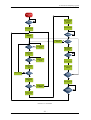
11. Flowchart and final programs
11.1. Flowchart
11.2. Final programs
11.2.1. General aspects in the communication
11.2.2. Main program
11.2.3. Client server program in the robot
11.2.4. Robot program
11.3. Picture of the final process
90
90
92
92
93
97
100
103
12. Conclusions: improvements and future applications
12.1. Conclusions
104
104
- ii -
Index
12.2. Improvements and future applications
104
13. Bibliography
106
APPENDIX.
A1.
Visual Basic learning programs
A2.
Visual Basic communication programs
A2.1
Code of program to control the belt
A2.2
Code of server program in the robot
A2.3
Code of Ethernet communication in the main PC
A3.
Visual Basic final programs
A3.1
Code of the main program
A3.2
Code of server program in the robot
A3.3
Code of Module added in server program
A4.
Datasheet of the motor
- iii -
108
117
117
120
124
126
126
142
150
154
Index
- iv -
0-Background and Objectives
CHAPTER 0
Background and Objectives
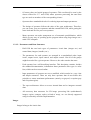
The current Project is developed in ACRO, Automatisering Centrum Research en
Opleiding, but these acronyms are more than only words. ACRO is a Research and project
Group in the field of automation and is a certified PROFIBUS COMPETENCE CENTER.
This group gives PROFIBUS training in a practically-oriented industrial environment and can
offer you a complete PROFIBUS service. Profibus is only one element of automation, ACRO
offers a complete package of trainings and services in automation.
The topics of the research group ACRO are:
-
Industrial real-time networks (fieldbus)
-
Real-time vision applications
-
Sensor based robotics
-
Real-time camera hardware
-
Real-time operating systems
This project consists in implementation of a Visual-servoing application. The
application will use a robot, a conveyor and an image-analyse-system. Visual-servoing means
that a robot is controlled real-time by analyses of images. In this way, data which are obtained
from the image are used to implement some applications like:
-
To track an object with the robot as farer as the field of action permit it.
To track an unknown outline with the robot.
To pick up a piece with the robot on a moveable conveyor
The available robot is a KUKA KR 3. The robot has 6 degrees of freedom, an own
operating system, a PROFIBUS Interface and an Ethernet Interface to communicate with the
objective world.
-1-
0-Background and Objectives
The vision system will consist of an USB camera “Basler Scout” or “IDS Ueye” with
lens and finally lightning. The software which analyses the images will use HALCON and the
computer application will be written in Visual Basic or C++.
The communication between the robot and the vision system (PC) will occur over
Ethernet or PROFIBUS and the communication between the computer and the conveyor over
PROFIBUS via OPC.
All these goals show an open field in which the project is developed. Because of this, all
the decisions made during the project are managed by the student in order to create a final
application inside of the defined objectives.
-2-
1-Introduction to HALCON programming
CHAPTER 1
Introduction to HALCON programming
1.1. – Introduction. Vision development environment
HALCON defines the state of the art in machine vision software. It provides an
extensive vision library. HALCON solves your task so fast and with highest accuracy.
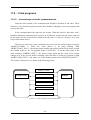
Solving image processing tasks is just one part of a complete solution, which comprises
other software components like process control or database access, and hardware components
from illumination to image acquisition devices and many other mechanical components. The
image processing system is easy to use.
HALCON takes cares of all the important aspects:
•
•
•
•
The software development is supported by the interactive tool HDevelop, which
enables a quick development of image processing tasks combined with an easy
integration into standard development environments like Microsoft Visual C++ via
the automatic code export.
The problem-oriented documentation covers all levels from a quick access to
important information up to a detailed discussion of advanced topics.
These descriptions are combined with hundreds of examples for an intuitive
understanding of the solutions, which can serve as templates to shorten the
development time.
Last but not least, HALCON provides open interfaces for efficient data exchange, to
integrate own operators, or to access specialized hardware round off the system.
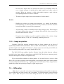
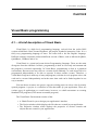
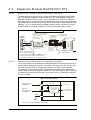
1.2. – Develop applications with HALCON
HALCON offers many ways for the application development. But to make full use of
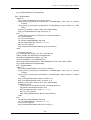
the architecture the mode depicted in figure 1.1 is recommended.
-3-
1-Introduction to HALCON programming
Picture 1.1. Three-step approach for the application development.
Image inspection, prototyping of the vision method, and the final development of the
vision method are done within HDevelop. Here, the program is structured into procedures in
which each procedure represents one sub task, like initialization, processing, and cleanup. The
main program is used only as a test environment to call the procedures by passing images and
receiving the results. This program is then exported to the language of the desired
programming environment.
The complete application is developed in a programming environment like Microsoft
Visual Studio. The code from HDevelop is imported, e.g., via an include statement. The user
interface and other necessary code is implemented using the normal mechanisms offered by
the given language. Finally, the project is compiled and linked.
Together with the HALCON library, the generated program represents the solution that
can, e.g., be loaded onto the destination machine or sent to a customer. An overview on the
philosophy of developing with HALCON can be seen in figure 1.1. The three-step approach
has several advantages:
-
Whenever needed the vision part can easily be optimized or extended because
HDevelop offers much better inspection and debugging facilities for image data
than the standard programming environments.
-
A newly exported HDevelop program can be incorporated into the programming
environment quite easily because the code is included and requires
modifications in the general code only if the parameters have been changed or
new procedures have been introduced. This closes the development cycle in a
natural manner.
-4-
1-Introduction to HALCON programming
-
Because the vision part is separated from the general code it can easily be
executed in a standalone manner. Furthermore, it can be given to others without
the need to pass the whole project. Especially in the case of support questions,
the HDevelop program with one or more images can quickly be sent to the
distributor.
1.2.1. – Architecture and data Structures
HALCON’s architecture, data structures, and internal mechanisms were developed
according to the philosophy that they should be:
1) Efficient. Efficient means that the execution time of each HALCON operator should
be as short as possible. Furthermore, the operator design has been made such that
combinations that are standard sequences or more complex tasks must still remain
efficient.
2) Open. The open architecture is important in two respects: First, it must be possible to
make use of HALCON from many different languages. Here, passing of external data
to HALCON and accessing internal data of HALCON must also be supported. Finally,
there must be transparent interfaces to integrate user-defined operators and nonstandard image acquisition devices. This open architecture allows, e.g., a simple
update to a new version of a frame grabber interface without changing the installation
of HALCON.
3) Standardized. Standardized means that the signatures, naming, and usage of operators
and data strict rules. This allows a quick learning combined with few possible errors.
4) Self-describing. HALCON provides detailed information about each operator and their
parameters not only in the documentation but also online via specialized operators.
1.2.1.1.- HALCON operators
Whenever any kind of functionality is used from the HALCON library, it is done via an
operator. The current version has more than 1100 of these operators. Most of them comprise
multiple methods, which are selected via parameters. A full list of all operators can be found
in the Reference Manuals or in the dialog Operators of HDevelop. Important features of
operators are:
-
There is no hierarchy among operators. From the software architecture point of
view, all operators are on the same level.
-5-
1-Introduction to HALCON programming
-
Of course, there are logical groups of operators. This can directly be seen by the
classes offered for C++ and COM, where operators processing the same data
type are used as members of the corresponding classes.
-
Operators have standardized rules for ordering input and output parameters.
-
The design of operators follows the rules of the open architecture. Therefore,
you can create your own operators and thus extend HALCON, while getting the
same look-and-feel for your own operators.
-
Many operators can make transparent use of automatic parallelization, which
allows an easy way of speeding up the program when using large images on a
multi-CPU computer.
1.2.1.2.- Parameters and Data Structures
-
HALCON has two basic types of parameters: iconic data (images etc.) and
control data (integers, handles, etc.).
-
The parameters for each operator are arranged in a standardized order: input
iconic, output iconic, input control, and output control. Not all of the groups
might be needed for a given operator. However, the order remains the same.
-
Each operator has a self-describing interface. This desription contains, besides
the standard documentation, information about parameters like types or value
lists, which can be accessed online.
-
Input parameters of operators are never modified, which results in a very clear
and simple sementics. There are only three operators that do not follow this
principle to ensure maximum performance (namely set grayval, overpaint gray
and overpaint region).
-
The open architecture allows to access internal data and to integrate external
data.
-
All necessary data structures for 2D image processing like (multichannel)
images, region, contours, tuples (a kind of array), etc. are directly supported
using an extremely efficient implementation.
Images
Images belong to the iconic data.
-6-
1-Introduction to HALCON programming
The major part of an image are the channels, i.e., matrices containing the gray values of
various pixel types.
For each image, the so-called domain specifies which part of the image is processed. It
thus acts as a region of interest (ROI). The domain is a HALCON region and can therefore be
defined very flexibly (from a simple rectangle to a set of unconnected pixels, see below).
Pixel data
An almost arbitrary content is possible, from standard 8-bit gray values to floating-point
numbers describing derivatives. For integer values one, two, and four byte versions (with and
without sign) are available. Besides this, floating point and complex images are available.
Finally, special data types for describing edge direction or hue values are supported.
Image Channels
A channel corresponds to an image matrix. Each image can have an arbitrary number of
channels. All channels of an image have the same size. Typical cases are: single-channel gray
value image, color image with three channels (e.g., RGB), or a multichannel image from a
multispectral sensor or as a result of texture filtering.
Coordinate Systems
The origin of an image is the upper left corner with coordinates (0,0). The single pixels
are accessed using row and column coordinates, like in a matrix. The coordinates range from
(0,0) up to (height-1, width-1). A pixel has an extent of 1, whereas the center of gravity of the
first pixel of an image is (0,0). This has the effect that this pixel ranges from (-0.5, -0,5) to
(0.5,0.5).
Regions
-
Regions belong to the iconic data.
-
A region is defined as a set of pixels, which are not necessarily limited to the
coordinate range of a given image.
-
The pixels of a region are not necessarily connected. This means that even an
arbitrary collection of pixels can be handled as one region. If connected
components as separate regions are needed, the operator connection can be
called.
-
Because the coordinates of pixels inside a region are not limited to the
coordinates of a given image, the region can be larger than the image, possibly
as the result of a dilation operation. Whether a region should be clipped to the
-7-
1-Introduction to HALCON programming
-
maximum image extents can be controlled using the operator set system with the
parameter value 'clip region'.
The implementation of regions is based on an efficient implementation of the
runlength encoding. This encoding facilitates low memory consumption with
efficient processing and easy use as regions of interest (domains).
-
Because of the implementation based on runlength encoding, it is possible to
have overlapping regions, e.g., as the result of a dilation of connected
components. This would not be possible with a classical implemention based on
label images.
-
The number of regions for an application is virtually unlimited.
-
XLDs belong to the iconic data.
-
XLD is the abbreviation for eXtended Line Description and comprises all
contour and polygon based data.
-
Subpixel accurate operators like edges sub pix return the contours as XLD data.
-
A contour is a sequence of 2D control points, which are connected by lines.
-
Typically, the distance between control points is about one pixel.
-
XLD objects contain, besides the control points, so-called local and global
attributes. Typical examples for these are, e.g., the edge amplitude of a control
point or the regression parameters of a contour segment.
-
Besides the extraction of XLD objects, HALCON supports further processing.
Examples for this are the selection of contours based on given feature ranges or
segmenting of a contour into lines, arcs, polygons or parallels.
XLDs
Control Tuples
-
Tuples are the generic data type for integer and floating point values as well as
strings. A variable of type tuple can be of any of the three basic types.
-
Besides single values, arrays of the basic types are supported. Therefore, one
variable can contain none, one, or an arbitrary number of values, where the types
of each element can be different.
-8-
1-Introduction to HALCON programming
-
In most cases, single values are treated in the same way as multiple values. If,
e.g., a feature operator is called with a single region one feature value is
returned. When the operator is called with multiple regions a tuple with the
corresponding number of values is returned.
-
The index of tuples range from 0 to the number of values minus 1.
-
Handles are references to complex data structures, e.g., models for the shapebased matching. For efficiency and data security reasons, not the entire structure
but only the handle is passed to the programmer.
-
All processing of data is controlled with a unique integer value. These integers
are magic numbers that must not be changed and can differ from execution to
execution and version to version.
-
Examples where handles are used are graphics windows, files, sockets, image
acquisition devices, OCR, OCV, measuring, matching, and so on.
Handles
1.2.2. – Image acquisition
Currently, HALCON provides interfaces about 40 frame grabbers in the form of
dynamically loadable libraries (Windows: DLLs; UNIX: shared libraries). These libraries are
installed together with the HALCON libraries. Library names start with the prefix HFG; the
libraries starting with parHFG are used by Parallel HALCON.
The HALCON frame grabber interface libraries form the bridge between software
provided by the frame grabber’s manufacturer and HALCON. They form a common, generic
interface that requires a small set of operators only.
If you successfully installed your frame grabber, all you need to do to access it from
HALCON is to call the operator open framegrabber, specifying the name of the frame grabber
and some additional information, e.g., regarding the connected camera. Then, images can be
grabbed by calling the operator grab image (or grab image async).
1.3. – HDevelop
HDevelop is a powerful environment for both prototyping and method development.
To use HDevelop you need to know just a few things. To load an example, select the menu
File > Open. This will open a file section dialog that shows the main directories of the
-9-
1-Introduction to HALCON programming
HDevelop examples underWindows). For beginners, it is recommended to select an example
from the directory Applications. As an alternative, the menu File > Open Example Program...
can be used. Here, a dialog that allows you to select examples based on different categories
instead of the actual location is opened.
After loading the file, the corresponding program code is displayed in the program
window. The used variables - so far not instantiated - can be seen in the variable watch
window. The program is now ready for execution.
Steps to run a program:
1. Press the Run button to execute the program. To continue at a stop statement, press
Run again.
2. Besides the Run button, HDevelop provides a Step button, which executes only a
single line and displays the results immediately afterwards. If the program contains
procedures, it might be of interest to use the buttons Step Into and Step Out.
3. To rerun the complete program the Reset button can be used. To rerun parts only,
simply click with the mouse to the left of the desired program line. This will reposition
the program counter. When executing the program anew it will then start at the newly
selected position.
Useful hints for HDevelop:
1. At the lower end of the main window, HDevelop provides a status bar. This displays
useful information in many cases. Especially during the execution, when the program
stops to visualize results or waits for a user interaction corresponding instructions are
given.
2. Many programs will automatically display relevant data in the graphics window.
Manual visualization can easily be achieved by double clicking on the icons in the
variable watch window.
3. Depending on the selected installation type, not all images used in an example
program might be available. In this case, we recommended to insert the HALCON CD
or to install the needed images.
4. Some programs use frame grabbers for image acquisition. If the corresponding frame
grabber type is not available, an error message will be raised. In this case, we
recommend to either use another example or to modify the parameters to fit to the
available hardware. Furthermore, if HDevelop Demo is used, no frame grabber
interfaces can be used, including the File frame grabber, which reads images from
files. If you want to use these programs, please use HDevelop.
- 10 -
1-Introduction to HALCON programming
1.4. – Using HALCON within Programming languages
HALCON offers three so-called language interfaces. They are libraries that enable you
to call the operators and to use the data types of the HALCON library in an easy way. Two
language interfaces are designed for specific languages. These are the C and the C++
interfaces. In contrast, the COM interface is independent of a given language. It can be used,
e.g., with Visual Basic, C#, or Delphi.
Independent of which programming language you choose, a suitable interface library
(HALCONc.*, HALCONcpp.*, HALCONx.*) together with the HALCON library
(HALCON.*) must be linked to the application. In addition to this, for C and C++ the
corresponding include files must be included.
For each language interface, the names of types, classes, the naming conventions of
operators, etc. may differ to be compliant with the typical rules that apply for the selected
language.
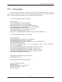
1.5. – Examples and applications
In order to explain the knowledge about the HALCON programming during the first
three weeks, subsequently there are series of shorts programs as a prelude to the final
program, used in the robot implementation.
First of these, it is necessary to acquire images through the camera by the following
program:
** Image Acquisition **
***************************
dev_close_window ()
close_all_framegrabbers ()
dev_open_window (0, 0, 640, 480, 'black', WindowHandle)
open_framegrabber ('DirectShow', 1, 1, 0, 0, 0, 0, 'default', 8, 'rgb', -1, 'false', 'default', 'default',
0, -1, AcqHandle)
grab_image_start (AcqHandle, -1)
*
while (true)
count_seconds (T1)
grab_image_async (Image, AcqHandle, -1)
*
Do something
count_seconds (T2)
Result := 1/(T2-T1)
endwhile
close_framegrabber (AcqHandle)
- 11 -
1-Introduction to HALCON programming
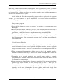
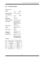
The following program looks for a transistor between any electronic devices, it makes a
distinction between these and it marks only the transistor. It can be seen in the picture below
(Picture 1.2.):
** Looking for a transistor **
*********************************
dev_close_window ()
close_all_framegrabbers ()
dev_open_window (0, 0, 640, 480, 'black', WindowHandle)
open_framegrabber ('DirectShow', 1, 1, 0, 0, 0, 0, 'default', 8, 'rgb', -1, 'false', 'default', 'default',
0, -1, AcqHandle)
grab_image_start (AcqHandle, -1)
*
dev_update_window ('off')
while (true)
count_seconds (T1)
grab_image_async (Image, AcqHandle, -1)
count_seconds (T2)
Result := 1/(T2-T1)
rgb1_to_gray (Image, GrayImage)
decompose3 (Image, r, g, b)
threshold (r, Region, 0, 25)
connection (Region, ConnectedRegions)
select_shape (ConnectedRegions, SelectedRegions, ['area','compactness'], 'and', [3000,1],
[4000,2])
shape_trans (SelectedRegions, RegionTrans, 'rectangle2')
boundary (RegionTrans, RegionBorder, 'inner')
dev_set_color ('red')
dev_set_line_width (2)
dev_set_draw ('margin')
dev_display (Image)
dev_display (RegionBorder)
endwhile
close_framegrabber (AcqHandle)
Picture 1.2. Looking for the transistor.
- 12 -
1-Introduction to HALCON programming
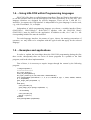
In the following program, HALCON detects if the position of the reluctance (circular
device) is correct. While the reluctance is on top, it marks with a green square. When it is
bottom or sideway, it shows up a message “Wrong position of the reluctance”:
** Detecting the position of the reluctance **
***************************************************
dev_close_window ()
close_all_framegrabbers ()
dev_open_window (0, 0, 640, 480, 'black', WindowHandle)
open_framegrabber ('DirectShow', 1, 1, 0, 0, 0, 0, 'default', 8, 'rgb', -1, 'false', 'default', 'default',
0, -1, AcqHandle)
grab_image_start (AcqHandle, -1)
*
dev_update_window ('off')
while (true)
count_seconds (T1)
grab_image_async (Image, AcqHandle, -1)
count_seconds (T2)
Result := 1/(T2-T1)
dev_set_color ('green')
dev_set_draw ('margin')
dev_set_line_width (2)
rgb1_to_gray (Image, GrayImage)
decompose3 (Image, r, g, b)
threshold (g, Region, 0, 53)
connection (Region, ConnectedRegions)
select_shape (ConnectedRegions, SelectedRegions, ['area','roundness'], 'and', [3000,0.65],
[4250,0.75])
shape_trans (SelectedRegions, RegionTrans, 'rectangle2')
boundary (RegionTrans, RegionBorder, 'inner')
area_center (RegionTrans, Area, Row, Column)
dev_display (Image)
if (Area>0)
dev_display (RegionBorder)
else
set_tposition (WindowHandle, 30, 100)
set_font (WindowHandle, '-Arial-18-*-*-*-*-1-')
dev_set_color ('yellow')
write_string (WindowHandle, 'Wrong position of the resistance')
endif
stop ()
endwhile
close_framegrabber (AcqHandle)
- 13 -
1-Introduction to HALCON programming
Picture 1.3.Position of the reluctance.
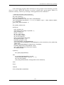
The third program extracts the outline of a single color object. For example, in the
Picture 1.4, HALCON draws the outline of a passport:
** Drawing edges **
************************
dev_close_window ()
close_all_framegrabbers ()
dev_open_window (0, 0, 640, 480, 'black', WindowHandle)
open_framegrabber ('DirectShow', 1, 1, 0, 0, 0, 0, 'default', 8, 'rgb', -1, 'false', 'default', 'default',
0, -1, AcqHandle)
grab_image_start (AcqHandle, -1)
while (true)
count_seconds (T1)
grab_image_async (Image, AcqHandle, -1)
count_seconds (T2)
Result := 1/(T2-T1)
threshold (Image, Region, 0, 70)
connection (Region, ConnectedRegions)
boundary (ConnectedRegions, RegionBorder, 'inner')
dilation_rectangle1 (RegionBorder, RegionDilation, 10, 10)
union1 (RegionDilation, RegionUnion)
dev_display (Image)
dev_set_color ('green')
dev_set_line_width (3)
dev_set_draw ('margin')
reduce_domain (Image, RegionUnion, ImageReduced)
edges_sub_pix (ImageReduced, Edges, 'lanser2', 0.5, 20, 40)
stop ()
endwhile
close_framegrabber (AcqHandle)
- 14 -
1-Introduction to HALCON programming
Picture 1.4.Drawing edges
- 15 -
2- KUKA robot. Overwiew and programming over KCP
CHAPTER 2
KUKA Robot. Overview and programming over KCP
2.1. – Robot Description. KUKA KR3
The KR3 robot and its variants are six-axis industrial robots designed for light payload
applications that require articulated motion in the horizontal and vertical planes.
Their main areas of application are:
- Machine loading and parts handling
- Laboratory automation
- Product testing
- Assembly
- Adhesive application
- Training
- Arc welding
- Machining task, such as grinding, polishing and deburring
Designed for a nominal 3 Kg payload, the KR 3 provides a powerful combination of
high-speed flexible automation, reliability and ease-of-use. The robot can be mounted upright
or inverted, and is sealed to IP54, allowing for a wide range of possible uses.
The brushless servomotors and high-stiffness harmonic drives used in the KR3 design
make it one of the fastest and most durable robots in its class. Absolute encoders built into
each joint allow the KR 3 to retain positional information, making it possible to turn on the
robot and be ready to go in mere seconds. Arm position parameters can be maintained in
memory for up to 2 months, even when the robot and controller are disconnected.
A fully integrated servo control network located within the robot makes the KR 3
virtually immune to interference from external electromagnetic radiation. This internal design
also allows for a smaller controller, and reduces the complexity of umbilical cable
management.
- 16 -
2- KUKA robot. Overwiew and programming over KCP
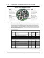
2.1. Principal components of the robot
Robot design
The ISO-standard mounting flange on the wrist allows a wide range of end effectors to
be used with the KR 3. The possible movements of the robot axes are depicted in Figure 2.2
2.2. Rotational axes and directions of rotation
The working range of the robot can be limited by means of software limit switches on
all axes. The working ranges of the main joints are mechanically limited by hardstops, which
can be pre-adjusted at the factory.
- 17 -
2- KUKA robot. Overwiew and programming over KCP
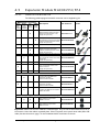
2.2. – Technical data
- 18 -
2- KUKA robot. Overwiew and programming over KCP
2.3. Critical dimensions KR 3 (mm)
- 19 -
2- KUKA robot. Overwiew and programming over KCP
2.4. Working envelope for KR3 (mm)
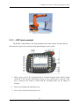
2.3. – Quick description of the robot system
A KUKA robot system is made up of the following components and is depicted in the
picture 2.5:
- Robot (1)
- Robot controller (3)
- KCP teach pendant (4)
- Connecting cables (2)
- Software
- Accessories
- 20 -
2- KUKA robot. Overwiew and programming over KCP
Picture 2.5. KUKA robot system
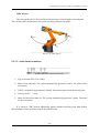
2.3.1. – KCP teach pendant
The KUKA Control Panel is the teach pendant for the robot system. The KCP has all
the functions required for operating and programming the robot system.
Picture 2.6. KCP
1. Mode selector switch. The operating mode is selected using the mode selector switch
on the KCP. The switch is activated by means of a key which can be removed. If the
key is removed, the switch is locked and the operating mode can no longer be
changed.
2. Drives On. Switches the robot drives on.
3. Drives Off. Switches the robot drives off.
- 21 -
2- KUKA robot. Overwiew and programming over KCP
4. Emergency Stop button.
5. Space Mouse. Jogs the robot.
6. Right-hand status keys. The status keys are used primarily for controlling the robot and
setting values.
7. Enter key. The enter key is used to close an active window or inline form. Changes are
saved.
8. Arrow keys. The arrow keys are used to jump from element to element in the user
interface.
9. Keypad.
10. Numeric keypad.
11. Softkeys. The icons change dynamically and always refer to the active window.
12. Start backwards key. The start backwards key is used to start a program backwards.
The program is executed step by step.
13. Start key. The start key is used to start a program.
14. Stop key. The stop key is used to stop a program that is running.
15. Window selection key. The window selection key is used to toggle between the main,
option and message windows. The selected window is indicated by a blue background.
16. Esc key. The esc key is used to abort an action on the user interface.
17. Left-hand status key. The status keys are used for controlling the program execution
and the robot movements.
18. Menu keys. The menu keys are used to open the menus.
The rear of KCP presents the disposition shown in Picture 2.7 (next page)
1. Rating plate.
2. Start key. The start key is used to start a program.
- 22 -
2- KUKA robot. Overwiew and programming over KCP
Picture 2.7. Rear of KCP.
3. Enabling switch (buttons 3, 4, 5) The enabling switches have 3 positions:
- Not pressed
- Center position
- Panic position
The enabling switch must be held in the center position in operating modes T1 and
T2 in order to be able to jog the robot. In the operating modes Automatic and
Automatic External, the enabling switch has no function.
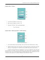
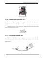
2.3.2. – Operating modes
The operating mode is selected using the mode selector switch on the KCP. The switch
is activated by means of a key which can be removed. If the key is removed, the switch is
locked and the operating mode can no longer be changed.
Picture 2.8. Modes in KCP
1. Test 2 (T2)
2. Automatic (AUT). For robot system without higher-level controllers. Only possible
with a connected safety circuit.
- 23 -
2- KUKA robot. Overwiew and programming over KCP
3. Automatic External (AUT EXT). For robot system with higher-level controller, e.g.
PLC. Only possible with a connected safety circuit.
4. Test 1 (T1)
2.3.3. – Changing user group
Different functions are available in the KSS, depending on the user group. The
following user groups are available:
-
User. User group for the operator
-
Expert. User group for the programmer. In this user group it is possible to switch
to the Windows interface.
-
Administrator. The range of functions is the same as that for the user group
"Expert". It is additionally possible, in this user group, to integrate plug-ins into
the robot controller.
When the system is booted, the user group "User" is selected by default. The user
groups "Expert" and "Administrator" are password-protected.
2.2.4. – Coordinate system
The following Cartesian coordinate systems are defined in the robot system:
WORLD
The World coordinate system is a permanently defined Cartesian coordinate system. It
is the root coordinate system for the Robroot and Base coordinate systems. By default, the
World coordinate system is located at the robot base.
ROBROOT
The Robroot coordinate system is a Cartesian coordinate system, which is always
located at the robot base. It defines the position of the robot relative to the World coordinate
system. By default, the Robroot coordinate system is identical to the World coordinate
system. $Robroot allows the definition of an offset of the robot relative to the World
coordinate system.
BASE
The Base coordinate system is a Cartesian coordinate system that defines the position of
the workpiece. It is relative to the World coordinate system. By default, the Base coordinate
system is identical to the World coordinate system. It is offset to the workpiece by the user.
- 24 -
2- KUKA robot. Overwiew and programming over KCP
2.2.5. – Tool calibration
During tool calibration, the user assigns a Cartesian coordinate system (TOOL
coordinate system) to the tool mounted on the mounting flange. The TOOL coordinate system
has its origin at a user-defined point. This is called the TCP (Tool Center Point). The TCP is
generally situated at the working point of the tool.
Advantages of the tool calibration:
- The tool can be moved in a straight line in the tool direction.
- The tool can be rotated about the TCP without changing the position of the TCP.
- In program mode: The programmed velocity is maintained at the TCP along the path.
A maximum of 16 TOOL coordinate systems can be saved. Variable:
TOOL_DATA[1…16].
The following data are saved:
•
X, Y, Z:
Origin of the TOOL coordinate system relative to the FLANGE coordinate
system.
•
A, B, C:
Orientation of the TOOL coordinate system relative to the FLANGE
coordinate system
Tool calibration consists of 2 steps:
1. Definition of the origin of the Tool coordinate system. The following methods
are available:
TCP calibration: XYZ 4-Point method
The TCP of the tool to be calibrated is moved to a reference point from 4
different directions. The reference point can be freely selected. The robot
controller calculates the TCP from the different flange positions.
TCP calibration: XYZ Reference method
In the case of the XYZ Reference method, a new tool is calibrated with a tool
that has already been calibrated. The robot controller compares the flange
positions and calculates the TCP of the new tool.
2. Definition of the orientation of the Tool coordinate system. The following
methods are available
- 25 -
2- KUKA robot. Overwiew and programming over KCP
Defining the orientation: ABC World method
The axes of the TOOL coordinate system are aligned parallel to the axes of the
WORLD coordinate system. This communicates the orientation of the TOOL
coordinate system to the robot controller.
Defining the orientation: ABC 2-Point method
The axes of the TOOL coordinate system are communicated to the robot
controller by moving to a point on the X axis and a point in the XY plane.
This method is used if it is necessary to define the axis directions with particular
precision.
The tool data can be entered manually.
Possible sources of data:
- CAD
- Externally calibrated tool
Tool manufacturer specifications
2.2.6. – Structure of a KRL program (KUKA Robot Language)
The picture below shows the structure of a KUKA Robot Language program:
Picture 2.9. KRL program
1. Def line. The Def line indicates the name of the program. If the program is a
function, the Def line begins with ‘Deffct’ and contains additional information.
2. Ini line. The Ini line contains initializations for internal variables and parameters.
This line mustn’t be deleted.
4. Home position. The Home position is not program-specific. It is generally used as
the first and last position in the program as it is uniquely defined and uncritical. The
Home position is stored by default in the robot controller.
22. End line. The End line is the last line in any program. If the program is a function,
the wording of the End line is ‘Endfct’.
- 26 -
2- KUKA robot. Overwiew and programming over KCP
2.2.7. – Programming motions
PTP motion
The robot guides the TCP along the fastest path to the end point. The fastest path is
generally not the shortest path and is thus not a straight line. As the motions of the robot axes
are rotational, curved paths can be executed faster than straight paths. The exact path of the
motion cannot be predicted.
Picture 2.10. PTP motion
LIN motion
The robot guides the TCP at a defined velocity along the shortest path to the end point.
The shortest path is always a straight line.
Picture 2.11. LIN motion
- 27 -
2- KUKA robot. Overwiew and programming over KCP
CIRC motion
The robot guides the TCP at a defined velocity along a circular path to the end point.
The circular path is defined by a start point, auxiliary point and end point.
Picture 2.12. CIRC motion
2.2.7.1.- Inline form for motions
Picture 2.13. Inline form for LIN motions
1. Type of motion (PTP, LIN, CIRC)
2. Name of the end point. The system automatically generates a name. The name can be
overwritten.
3. CONT: end point is approximated; [blank]: the motion stops exactly at the end point
4. Velocity (0.001… 2 m/s)
5. Name for the motion data set. The system automatically generates a name. The name
can be overwritten.
If is chosen a CIRC motion additionally appears another auxiliary point what defines
the coordinates of the auxiliary point to describe de circle.
- 28 -
2- KUKA robot. Overwiew and programming over KCP
Option window “Frames”
Picture 2.14. Frames
1. Tool selection. Range of values [1-16]
2. Base selection. Range of values [1-32]
3. External TCP. False: Tool on mounting flange
True: Fixed tool
Option window “Motion parameter” (in PTP motions)
Picture 2.15. Motion parameter
1. Acceleration. Refers to the maximum value specified in the machine data [1-100%]
2. Furthest distance before the end point at which approximate positioning can being.
This box is only displayed if CONT has been selected in the inline form [0-100%]
In CIRC and LIN motions the orientation of a tool can be different at the start point
and end point of a motion. It can be selected by a new option called “Orientated Control
Selection”. There are several different types of transition from the start orientation to the end
orientation. Three options are available: Standard, Wrist PTP and Constant.
- 29 -
2- KUKA robot. Overwiew and programming over KCP
2.4. – Initial programs
The programs below show the structure of an easy program using point to point motion,
circular, linear and some coordinates given by the user to move the robot some distances in
millimeters (Picture 2.17).
Picture 2.16. First program
Picture 2.17. Second program
- 30 -
2- KUKA robot. Overwiew and programming over KCP
Picture 2.18. Third program
- 31 -
3-Manufacturing the surface of work
CHAPTER 3
Manufacturing the surface of work
3.1. – Surface work and possible alternatives
The robot has its own support but it needs an additional surface to work, where are
situated the conveyor, the camera, etc. This involves thinking about different ways to get the
best solution.
Firstly was chosen a metal plate fixed on the base of the robot. But it wasn’t a good idea
because the robot could produce movements on the plate, it could make errors while the
camera is grabbing images and even it would be an unstable structure.
Afterwards was decided that the best choice was to design a table, more stable and
robust than previous plate. To design this, at the beginning it was necessary to take measures
about the maximum length that the robot can reach during the movements. The work surface
will be on the same level as the robot base. Take into account that the working envelope
measures displayed in the previous chapter (Picture 2.4), the required table needs the
following dimensions:
- Length: 1220 mm
- Width: 780 mm
- Height: 865 mm
The next step is to check if there are enough materials which are necessary to make the
table (1220 x 780) in the workplace.
3.2. – Features and reasons
Looking at the robot scope, it is common to think that the table is enough to implement
the process (too big), but it’s thought to hold another future process.
- 32 -
3-Manufacturing the surface of work
The color of the table is white to help and simplify the images later collected through
the camera. In this way Halcon programming is more efficient and it reduces the mistakes.
The steel structure of the table is colored brown to conserve the esthetic form of the remaining
tables inside the department.
The table legs are adjustable in height to allow a fine-regulation.
3.3. – Camera support
The camera presents a new problem. The best position to place it is above the robot in
the central part of the table, but it has to keep a certain distance to not crash the robot while it
is moving.
In consequence of this, the camera support has an L shape to avoid a collision with the
robot. By tudying the robot movements and by considering the security distances, the final
shape of the support is obtained.
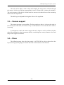
3.4. – Plans
The following pages show the plans made in AUTOCAD in order to know how the
layout of the project is going to be and to know the real measures of the elements.
- 33 -
3-Manufacturing the surface of work
General plan
- 34 -
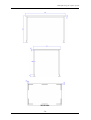
3-Manufacturing the surface of work
Camera Support
- 35 -
3-Manufacturing the surface of work
Work table
- 36 -
4- Visual Basic programming
CHAPTER 4
Visual Basic programming
4.1. – A brief description of Visual Basic
Visual Basic is a high level programming language evolved from the earlier DOS
version called Basic. Basic means Beginners' All-purpose Symbolic instruction Code. It is a
fairly easy programming language to learn. The codes look a bit like English Language.
Different software companies produced different version of Basic, such as Microsoft QBasic,
QuickBasic, GWBasic and so on.
Visual Basic is a visual and events driven Programming Language. These are the main
divergence from the old Basic. In Basic, programming is done in a text-only environment and
the program is executed sequentially. In Visual Basic, programming is done in a graphical
environment. Because users may click on a certain object randomly, so each object has to be
programmed independently to be able to response to those actions (events). Therefore, a
Visual Basic Program is made up of many subprograms, each has its own program codes, and
each can be executed independently and at the same time each can be linked together in one
way or another.
You can choose to start a new project, open an existing project or select a list of recently
opened programs. A project is a collection of files that make up your application. There are
various types of applications we could create; however, we shall concentrate on creating
Standard EXE programs (EXE means executable program).
The Visual Basic Environment consists of the:
•
A Blank Form for you to design your application's interface.
• The Project window which displays the files that are created in your application.
• The Properties window which displays the properties of various controls and
objects that are created in your applications.
- 37 -
4- Visual Basic programming
It also includes a Toolbox that consists of all the controls essential for developing a VB
Application. Controls are tools such as text box, command button, label, combo box, picture
box, image box, timer and other objects that can be dragged and drawn on a form to perform
certain tasks according to the events associated with them. Additional objects can be added by
clicking on the project item on the menu and click on components on the drop-down list.
4.2. – Drawing the user interface
There are three primary steps involved in building a Visual Basic application:
1. Draw the user interface
2. Assign properties to controls
3. Attach code to controls
Visual Basic operates in three modes
⇒ Design mode - used to build application
⇒ Run mode - used to run the application
⇒ Break mode - application halted and debugger is available
Six windows appear when you start Visual Basic
The Main Window consists of the title bar, menu bar, and toolbar. The title bar indicates
the project name, the current Visual Basic operating mode, and the current form. The menu
bar has dropdown menus from which you control the operation of the Visual Basic
environment. The toolbar has buttons that provide shortcuts to some of the menu options. The
main window also shows the location of the current form relative to the upper left corner of
the screen and the width and length of the current form.
Picture 4.1. Title bar, menu bar and toolbar
The Form Window is central to developing Visual Basic applications. It is where you
draw your application.
- 38 -
4- Visual Basic programming
Picture 4.2. Form window
The Toolbox is the selection menu for controls used in your application.
Picture 4.3. Toolbox
The Form Layout Window shows where (upon program execution) your form will be
displayed relative to your monitor’s screen:
Picture 4.4. Form layout window
The Properties Window is used to establish initial property values for objects. The dropdown box at the top of the window lists all objects in the current form. Two views are
available: Alphabetic and Categorized. Under this box are the available properties for the
currently selected object.
- 39 -
4- Visual Basic programming
Picture 4.5. Properties window
The Project Window displays a list of all forms and modules making up your
application. You can also obtain a view of the Form or Code windows (window containing
the actual Basic coding) from the Project window.
Picture 4.6. Project window
4.3. – Learning to program in Visual Basic
In order to make a program that contains the process followed by the robot over the
camera, the first step is to start programming some simple programs and then, with the
knowledge acquired, make the last application program for the project.
In this way, the programs made during the period of learning to program in Visual
Basic are attached in the Appendix 1 (the window program and the code of each one).
- 40 -
5-Motor-PLC connection via PFOFIBUS
CHAPTER 5
Motor-PLC connection via PROFIBUS
5.1. – Components and connection cables
The goal of the project includes a conveyor which moves one object on the table. The
conveyor needs a step motor to run. The power to move the conveyor is supplied by a motor
of the MAC’s family, specifically the motor MAC95 FP4 (datasheet in the Appendix 4).
The motor has a PROFIBUS connection and it requires a PLC to be commanded. The
PLC is from Siemens, specifically from the family S7-300 (S7 CPU 314-6CG03-0AB0).
The motor has two connections; one is the power input and the other is the PROFIBUS
connector. The power is provided by a power supply which supplies the necessary voltage to
the motor (between 12 and 48 VDC). The maximum voltage in the power supply is 30 V
which is used.
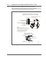
The pin connections are detailed in the pictures below:
Picture 5.1. MAC00 FP4 connectors
- 41 -
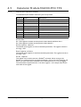
5-Motor-PLC connection via PFOFIBUS
Table 5.1. Detailed pin connections
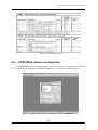
5.2. – PROFIBUS network configuration
The PROFIBUS network configuration is used to connect the motor (slave) and the
PLC (master) by the program of Siemens, Simatic Step 7. Each step is detailed below:
Picture 5.1. First picture in PROFIBUS network configuration
- 42 -
5-Motor-PLC connection via PFOFIBUS
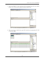
1. Open the program Simatic Step 7 and create a new project. The following window
will appear (Picture 5.2)
Picture 5.2. Second picture in PROFIBUS network configuration
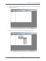
2. Insert a new object, in this case the PLC is from the family S7-300
Picture 5.3. Third picture in PROFIBUS network configuration
- 43 -
5-Motor-PLC connection via PFOFIBUS
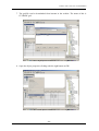
3. Access into SIMATIC 300(1) on the left side, the program shows the next window
(Picture 5.4). Choose the rail in Rack-300 and do double click
Picture 5.4. Fourth picture in PROFIBUS network configuration
4. Then is necessary to look for the exact PLC in the list on the right side (S7 CPU
314-6CG03-0AB0)
Picture 5.5. Fifth picture in PROFIBUS network configuration
- 44 -
5-Motor-PLC connection via PFOFIBUS
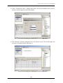
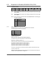
5. The program shows a window with properties in which is necessary to indicate the
MPI address, in this case is the number 2.
Picture 5.6. Sixth picture in PROFIBUS network configuration
6. Afterwards the program has to recognize the motor, so it needs a *.gsd file of the
motor which has to be installed.
Picture 5.7. Seventh picture in PROFIBUS network configuration
- 45 -
5-Motor-PLC connection via PFOFIBUS
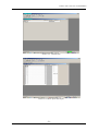
7. The gsd-file can be downloaded from internet in the website. The name of this is
JVLI06BC.gsd
Picture 5.8. Eighth picture in PROFIBUS network configuration
8. Open the object properties clicking with the right button on DP.
Picture 5.9. Ninth picture in PROFIBUS network configuration
- 46 -
5-Motor-PLC connection via PFOFIBUS
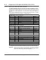
9. In the object properties window click on properties.
Picture 5.9. Ninth picture in PROFIBUS network configuration
10. Afterwards select in the menu bar Parameters, the address is just the number which
identify the network (realize that this address is not the same as the MPI address).
Revise if it’s correct and click on New.
Picture 5.10. Tenth picture in PROFIBUS network configuration
- 47 -
5-Motor-PLC connection via PFOFIBUS
11. Select Transmission Rate 1.5Mbps and Profile Universal (DP/MFS) and click Ok,
the new network appears in the last window.
Picture 5.11. Eleventh picture in PROFIBUS network configuration
12. The network is already configured like in the picture below. Find on the right side
the motor file (MAC00-FP) and select it.
Picture 5.12.Twelveth picture in PROFIBUS network configuration
- 48 -
5-Motor-PLC connection via PFOFIBUS
13. Write the motor address which was selected in the switches inside the motor (for
more information, see the motor datasheet in the Appendix 4). In this case the first
and second switches are on, so it indicates the address 3.
Picture 5.13. Thirteenth picture in PROFIBUS network configuration
14. Finally, the connection is made, see the picture below.
Picture 5.14. Fourteenth picture in PROFIBUS network configuration
- 49 -
5-Motor-PLC connection via PFOFIBUS
15. The main program has the next appearance.
Picture 5.15. Fifteenth picture in PROFIBUS network configuration
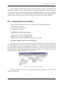
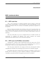
5.3. – Testing the motor variable values
To test the motor and to select the best values of the variables which provide a good
working of it. The program Simatic Step 7 offers a tool to monitor and modify the parameters
of the motor. It is possible to use this tool with the motor datasheet and the different kind of
registers which the motor has programmed. All this information is attached in Appendix 4.
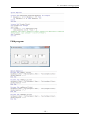
To access in modifying/monitoring variables, click in the toolbar “PLC” and then in
“Monitor/Modify Variables”. The window in the picture 5.16 appears. Afterwards introduce
the inputs and outputs defined in the motor. In this case there are 9 outputs and 8 inputs
shown in the picture 5.17. After some tests it would be clear which registers and values of
each parameter like velocity, acceleration, torque, etc. are used. Those values will be initially
introduced in the motor.
Decisions about every value are detailed in the following chapter. Also the problems
with the link between the motor and the conveyor are discussed.
- 50 -
5-Motor-PLC connection via PFOFIBUS
Picture 5.16. Variable table
Picture 5.17. Motor inputs and outputs
- 51 -
6- Step 7 program for the conveyor
CHAPTER 6
Step 7 program for the conveyor
6.1. – Requirements
Firstly the motor is joined directly with the conveyor in one side. The motor is used for
applications of high velocity, so it may have some problems when it is connected directly to
the conveyor due to the velocity of this has to be slow. To solve this problem in the test mode
explained in the previous chapter, many register were tested to adjust the best values of each
one. After many tests these values were chosen but the motor had a strange comportment
because it worked in low velocity and high torque. So it’s impossible to move the conveyor
itself. For this reason, afterwards the connection will be modified adding a component which
reduces the velocity. The initials data will be shown in this chapter. Maybe these won’t be the
latest data.
The program in Step 7 for the conveyor consists in a start/stop program controlled by
some switches connected in the PLC. The data that has to be included the first time in the
motor to control the velocity, acceleration…
The software of the motor has some registers that can be selected in order to choose one
of them depending on the application (see Appendix 2). The used registers are:
- Register 2 (with value 1 to start the motor)
- Register 5 (to select the velocity)
- Register 6 (to select the acceleration)
- Register 7 (to select the torque)
- Register 13 (to select the inertia)
6.2. – Step 7 program
Subsequently is explained the program in Step 7 which is used in the application for
moving the conveyor:
- 52 -
6- Step 7 program for the conveyor
1. Open the OB1 and write the required inputs and outputs.
Picture 6.1. Inputs
Picture 6.2. Outputs
- 53 -
6- Step 7 program for the conveyor
2. Move each data to the correct input/output of the motor.
Picture 6.3. Move data
Picture 6.4. Move data
- 54 -
6- Step 7 program for the conveyor
3. Introduce Function Blocks with the inputs and outputs made. Include also their
equivalent switches which enable each one. Write the correct values in each data, it
means, with the switch 125.0 in low, in register 5 the value 50 is introduced (value
of speed) and after it is sent over the PLC to the motor.
Picture 6.5. Two function blocks
Picture 6.6. One function block and one function graph
- 55 -
6- Step 7 program for the conveyor
4. The initial input data has to be made in a specific function of Step 7, this function is
the S7 Graph, in the way of the pictures below. It consists in a “grafcet” that allows
to introduce the written value in each register.
Picture 6.7. Graph of the data values
Picture 6.8. Graph of the data values
- 56 -
6- Step 7 program for the conveyor
Picture 6.9. Main program aspect
- 57 -
7- Camera: location, lighting and calibration
CHAPTER 7
Camera: location, lighting and calibration
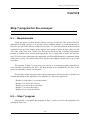
7.1. – Camera. Properties and location
The camera which is chosen is a camera of the IDS company (Imaging Development
Systems), specifically an uEye UI-146xLE model, SXGA (2048x1536).
2048x1536)
The uEye LE 146x models are equipped with a light-sensitive 1/2". Sensor with rolling
shutter which acquires 11 frames per second in fullframe-mode.
Characteristics: max. 11 fps, 220 fps in AOI-mode with 320x240 pixels 1/2" CMOS
sensor, rolling shutter, progressive scan Exposure: 57 µs - 1,75 s (freerun mode) Binning
horizontal and vertical Subsampling horizontal and vertical AOI horizontal and vertical
Picture 7.1. Camera uEye
This camera is perfect for the process because it reduces size and it has a high
resolution, as well as a progressive scan grabbing images.
Taking into account the maximum reach of the robot as well as the tool length and the
camera lens length. The support of the camera was made in order to not to damage it. The
camera is situated on the top of the workspace, just in the middle of the table and at an
altitude of 1160 mm. The camera is joined with the support by a screw with two nuts, one to
fix in the support and another to fix the camera and not let movements in the camera.
- 58 -
7- Camera: location, lighting and calibration
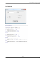
7.2. – Choosing the correct lens
The lens is as important as the illumination of the process. It defines the vision field of
the camera which will be the robot “eye”. To calculate the correct lens a program in Visual
Basic is used which includes the equation with the relations between the focus and the
dimensions on the surface of work.
The picture below shows the result of the program and the appropriate lens used in the
camera:
Picture 7.2. Calculating the focus
The data include in the equation are:
- Length from the table to the camera = 1150 mm
- Width of the table = 1120 mm
- ½ format = 6.4 mm
So, the focus is 6.0327 mm and then the camera requires is a 6 mm lens
7.3. – Lighting the surface
Lighting is the most important paragraph when cameras are used. A good illumination
enable to recognize each object in an easier way. Some parameters like brightness, contrast…
need to be controlled.
The first step is to choose the best for the project and to check which location is the
best.
- 59 -
7- Camera: location, lighting and calibration
After some tests, the lighting selected is provided by two fluorescent tubes located on
the support of the camera, far away from the robot reach. These fluorescent tubes have to run
with high frequency. The camera grabs more than 50 frames per second and because of this
some dimming parts can appear.
The two fluorescent tubes are 13 W each one with a length of 530 mm; they emit a
uniform lighting without too brightness in the center, otherwise the white color of the surface
would reflex the light and the quality of the images would be bad.
For the tubes it is necessary to use another piece holding up these. In this case the
support will be made of wood. The measures and location of this are selected by the user but
these setting don’t need a high precision.
A Quicktronic Intelligent QTi dimmable is a device which ensures flicker-free operation
of the lamps throughout the entire dimming range from 100 to 1%; specifically the device
Quicktronic Intelligent QTP 2x18/230-240 is utilized in the project. The picture below shows
the physical form of this, the next picture expose it the electric diagram to make the
connection between the lamps, the Quicktronic and the electric network.
Picture 7.3. Quicktronic Intelligent QTP 2x18/230-240
Picture 7.4. Electric diagram
The cables have two colors, one for each lamp (white and red) and they are hold in the
camera support by bridges. The Quicktronic is also holding up here too.
- 60 -
7- Camera: location, lighting and calibration
7.4. – Calibrating the coordinates on the work area
When the lighting and the lens are correct and connected, the next step consists in adjust
the data of the camera in the program HALCON, modifying some parameters to get the best
quality during the recording.
** Adjusting new parameters in uEye camera **
******************************************************
close_all_framegrabbers ()
open_framegrabber ('uEye', 2, 2, 0, 0, 0, 0, 'default', 8, 'gray', -1, 'false', 'UI146xLE-C',
-1, AcqHandle)
set_framegrabber_param (AcqHandle, 'contrast', 256)
set_framegrabber_param (AcqHandle, 'exposure', 10.3157)
set_framegrabber_param (AcqHandle, 'frame_rate', 27.542)
set_framegrabber_param (AcqHandle, 'gain_master', 35)
grab_image_start (AcqHandle, -1)
while (true)
grab_image_async (Image, AcqHandle, -1)
'1', 0,
* Do something
endwhile
close_framegrabber (AcqHandle)
The function set_framegrabber_param modify some parameters; in this case the
parameters changed are: contrast, exposure, frame rate and gain master. On the other hand, in
the function open_framegrabber the camera has been selected to record only half the pixels.
All this changes allows a faster image acquisition with an optimal image quality.
Once parameters are adjusted, the calibration can start. The calibration is done by a tool
like a calibration plate called “caltab” (see it in the picture below), it’s a tool designed by
HALCON Company for calibrating surfaces in real coordinates. Therefore, a program is made
which takes pictures with the caltab in different positions around the table.
Picture 7.5. Caltab
- 61 -
7- Camera: location, lighting and calibration
The next program takes pictures and it records one image in the map “images2” with a
three number from 000. Then the program could be executed once, the caltab is situated in
another position and execute again following this process. The pictures would be a .tiff file:
** Logging images for calibration **
******************************************
close_all_framegrabbers ()
dev_close_window ()
open_framegrabber ('uEye', 2, 2, 0, 0, 0, 0, 'default', 8, 'rgb', -1, 'false', 'UI146xLE-C', '1', 0, -1,
AcqHandle)
dev_open_window (0, 0, 512, 380, 'black', WindowHandle)
set_framegrabber_param (AcqHandle, 'contrast', 256)
set_framegrabber_param (AcqHandle, 'exposure', 10.3157)
set_framegrabber_param (AcqHandle, 'frame_rate', 27.542)
set_framegrabber_param (AcqHandle, 'gain_master', 30)
* set_framegrabber_param (AcqHandle, 'white_balance', 'auto')
Counter := 0
while (true)
grab_image_start (AcqHandle, -1)
grab_image_async (Image, AcqHandle, -1)
write_image (Image, 'tiff', 0, './images2/' + (Counter$'03') + '.tiff' )
Counter := Counter + 1
stop ()
endwhile
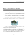
Subsequently, one of the images taken during the calibration are seen as well as the
caltab’s contour and dots that the program HALCON has drawn.
Picture 7.6. Calibration picture
- 62 -
7- Camera: location, lighting and calibration
The following program opens each picture and recognizes the caltab in each position on
the table. Important data in the program which could change for detecting the caltab are the
data the functions find_caltab and find_marks_and_pose.
The function camera_calibration is a powerful tool in HALCON and it computes the
final calibration and usually it takes several seconds to be executed. In the last part of this
there are two functions which create two files with the calculated parameters.
** Calibrating the surface of work **
******************************************
read_image (Image, './images2/000.tiff')
get_image_pointer1 (Image, Pointer, Type, Width, Height)
dev_close_window ()
dev_open_window (0, 0, Width*0.60, Height*0.60, 'black', WindowHandle)
dev_update_window ('on')
StartCampar := [0.006,0,0.0000032,0.0000032,512,384,1024,768]
* Calibration
Counter := 0
NRows := []
NCols := []
NStartpose := []
caltab_points ('caltab.descr', X, Y, Z)
for i := 0 to 26 by 1
read_image (Image, './images2/' + (i$'03') + '.tiff' )
dev_set_draw ('margin')
dev_set_line_width (3)
find_caltab (Image, Caltab, 'caltab.descr', 3, 90, 3)
find_marks_and_pose (Image, Caltab, 'caltab.descr', StartCampar, 100, 10, 18, 0.5, 15, 100,
RCoord, CCoord, StartPose)
dev_set_color ('red')
disp_cross (WindowHandle, RCoord, CCoord, 6, 0)
tuple_concat (NRows, RCoord, NRows)
tuple_concat (NCols, CCoord, NCols)
tuple_concat (NStartpose, StartPose, NStartpose)
endfor
stop ()
dev_open_window (0, 0, 512, 512, 'black', WindowHandle)
camera_calibration (X, Y, Z, NRows, NCols, StartCampar, NStartpose, 'all', CamParam,
NFinalPose, Errors)
write_cam_par (CamParam, 'campar.dat')
tuple_select_range (NFinalPose, 0, 6, Pose)
write_pose (Pose, 'campose.dat')
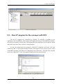
After the calibration, the program necessary for the project can be made and with it
takes measures from a central point defined in the program and another object situated on the
work area.
- 63 -
7- Camera: location, lighting and calibration
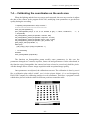
To show this, in the next picture there is a meter to measure the distance between the
center considered by the camera (red point) and the center of the black ball. The program
shows the distance between this center and the ball on the bottom. Can be checked than the
coordinates are exact because the center of the ball is just in a distance of 40 mm and the
program returns this value.
Picture 7.7. First real coordinates
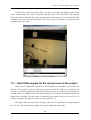
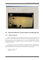
7.5. – HALCON program for the real process of the project
The process to implement consists in a black ball placed everywhere on the table, the
ball has to be picked up by the robot and put down inside the white box situated on the
conveyor. For this are going to be defined two regions in order to recognize easily each object
on each surface. In Chapter 3 the color of the table white was chosen to help and simplify the
images later collected. For this reason a black ball and a dark conveyor are used. So it is
easier to recognize the white box on the conveyor (Picture 7.7)
The edges of the conveyor have a soft gray color and it’s a problem to recognize just the
box. To solve this problem, these edges are covered with black isolate tape.
- 64 -
7- Camera: location, lighting and calibration
After that, HALCON program can confuse itself when it is detecting the ball and this is
quite near to the conveyor. The best way to answer the problem is leaving a small strip
without isolate tape in the side of the table, with this strip there isn’t problems with none
object.
For the last application will be necessary to get the coordinates of the central point of
the ball and the box. As each one has its own surface to be placed, two regions are going to be
defined. The box region is defined like a rectangle which contains the conveyor and the ball
region like an ellipse which contains the area of the maximum reach of the robot in correct
position to pick up objects. Additionally the program needs to be able to store the point where
the user wants to stop the conveyor.
So there are three steps, first to know if ball and box are inside the area permitted,
second to know when box is in position defined by the user and third to get the real
coordinates (X axis and Y axis). The HALCON program for all of these steps is:
**Final HALCON program (regions, positions and coordinates)**
**********************************************************************
dev_open_window (0, 0, 512, 512, 'black', WindowHandle)
read_cam_par ('campar01.dat', CamParam1)
read_pose ('campose01.dat', Pose1)
set_origin_pose (Pose1, 0, 0, 0, PoseNewOrigin1)
close_all_framegrabbers ()
open_framegrabber ('uEye', 2, 2, 0, 0, 0, 0, 'default', 8, 'rgb', -1, 'false', 'UI146xLE-C', '1', 0, -1,
AcqHandle)
set_framegrabber_param (AcqHandle, 'frame_rate', 27.542)
set_framegrabber_param (AcqHandle, 'contrast', 256)
set_framegrabber_param (AcqHandle, 'exposure', 10.3157)
set_framegrabber_param (AcqHandle, 'gain_master', 35)
grab_image_start (AcqHandle, -1)
dev_update_window ('off')
while (1)
** Looking for the ball **
grab_image_async (Image, AcqHandle, -1)
set_origin_pose (Pose1, 0.077595, 0.03263, 0, PoseNewOrigin1)
dev_display (Image)
decompose3 (Image, red, green, blue)
rgb3_to_gray (red, green, blue, ImageGray)
disp_cross (WindowHandle, 350, 540, 6, 0)
gen_ellipse (Ellipse, 0, 510, -0.07, 480, 410)
reduce_domain (ImageGray, Ellipse, ImageReduced1)
threshold (ImageReduced1, Region, 0, 15)
connection (Region, ConnectedRegions)
select_shape (ConnectedRegions, SelectedRegions, 'area', 'and', 1200, 5000)
select_shape (SelectedRegions, SelectedRegions1, 'roundness', 'and', 0.5, 1)
- 65 -
7- Camera: location, lighting and calibration
fill_up (SelectedRegions1, RegionFillUp)
Ball := |RegionFillUp|
if (Ball =1)
area_center (RegionFillUp, Area, Row, Column)
image_points_to_world_plane (CamParam1, PoseNewOrigin1, 350, 540, 'm', Xcenter,
Ycenter)
image_points_to_world_plane (CamParam1, PoseNewOrigin1, Row, Column, 'm', Xball,
Yball)
distance_pp (Xcenter, Ycenter, Xball, Yball, DistanceBall)
disp_cross (WindowHandle, Row, Column, 6, 0)
else
** When ball is not inside the robot reach, it shows a message **
dev_display (Ellipse)
dev_set_draw ('margin')
set_tposition (WindowHandle, 640, 640)
set_font (WindowHandle, '-Arial-14-*-*-*-*-1-')
dev_set_color ('yellow')
write_string (WindowHandle, 'Ball out of the robot reach')
endif
** Looking for the box **
gen_rectangle2 (Rectangle2, 110, 480, -0.05, 500, 70)
reduce_domain (red, Rectangle2, ImageReduced)
threshold (ImageReduced, Region1, 45, 255)
connection (Region1, ConnectedRegions1)
select_shape (ConnectedRegions1, SelectedRegions2, 'area', 'and', 9000, 12000)
fill_up (SelectedRegions2, RegionFillUp1)
Box := |RegionFillUp1|
if (Box = 1)
area_center (RegionFillUp1, Area1, Row1, Column1)
image_points_to_world_plane (CamParam1, PoseNewOrigin1, 350, 540, 'm', Xcenter,
Ycenter)
image_points_to_world_plane (CamParam1, PoseNewOrigin1, Row1, Column1, 'm', Xbox,
Ybox)
disp_cross (WindowHandle, Xcenter, Ycenter, 6, 0)
disp_cross (WindowHandle, Row1, Column1, 6, 0)
distance_pp (Xcenter, Ycenter, Xbox, Ybox, DistanceBox)
if (Column1>=370)
** When box is in the column selected, a message appears **
set_tposition (WindowHandle, 640, 640)
set_font (WindowHandle, '-Arial-14-*-*-*-*-1-')
dev_set_color ('yellow')
write_string (WindowHandle, 'Box in correct position')
endif
else
set_tposition (WindowHandle, 640, 640)
set_font (WindowHandle, '-Arial-14-*-*-*-*-1-')
dev_set_color ('yellow')
write_string (WindowHandle, 'Box out of conveyor')
- 66 -
7- Camera: location, lighting and calibration
endif
endwhile
At the beginning of the program there are two new commands read_cam_par and
read_pose, these are utilized to read the files created during the calibration. The central point
of the image is selected by the user, in this case (Row: 350, Column: 540); to adjust it in the
program, with set_origin_pose, the initial point Pose1 defined as the central dot in the first
image acquired with the caltab can be changed as follows: set_origin_pose (Pose1, 0.077595,
0.03263, 0, PoseNewOrigin1). Those values were taken with the program to prevent errors.
The following code has two parts clearly defined, in the first one it is trying to detect if
ball is inside or outside of the robot reach. With the command gen_ellipse and after with
reduce_domain the work area available by the robot is defined, the program only works in this
specific area. After this with the select_shape command, it recognizes the ball and then it
takes the area_center. An important function is image_points_to_world_plane because this
function transforms points in the image to real coordinates in the world. The second part is
similar, only changes the region (a rectangle) and it includes the position where the box is in
the correct position.
- 67 -
8- OPC communication
CHAPTER 8
OPC communication
8.1. – OPC overview
OPC is open connectivity in industrial automation and the enterprise systems that
support industry. Interoperability is assured through the creation and maintenance of open
standards specifications. There are currently seven standards specifications completed or in
development.
Based on fundamental standards and technology of the general computing market, the
OPC Foundation adapts and creates specifications that fill industry-specific needs. OPC will
continue to create new standards as needs arise and to adapt existing standards to utilize new
technology.
OPC Server DP enables easy access to Profibus DP devices. Profibus networks can
automatically be configured and diagnosed. This ensures extremely easy network
administration and enables flexible access to individual components.
8.2. – OPC sever via Profibus connection
Standard OPC is utilized to make communication between the motor and a CP 5611
card (integrated on the PC). This card is used to connect programming devices and PCs to
Profibus up to 12 Mbit/s and to the multipoint MPI interface of Simatic S7.
OPC will connect with the PLC, the computer and the motor; that integration could be
commanded by Visual Basic later, following an OPC protocol in a Visual Basic program.
Next pictures show how to make the OPC connection over Profibus in order to get a
flexible access of each device as well as integrate everything in a final program made in
Visual Basic (remember that HALCON programs can be used in Visual Basic).
- 68 -
8- OPC communication
8.2.1. – Create an OPC connection
Open a new Simatic project, add a new PC station and include the OPC Server indicated
in Picture 8.2
Picture 8.1. First Step
Picture 8.2. Second step
- 69 -
8- OPC communication
Insert the file corresponding to the CP card integrated in the computer, in this case
CP5611. Set an address for the new device (in this case 6, remember that the PLC has address
2, the motor address 3)
Picture 8.3. Third step
Picture 8.4. Fourth step
- 70 -
8- OPC communication
In “object properties”, include the new network done like it was explained in chapter 5.
The program has the following appearance (Picture 8.6):
Picture 8.5. Fifth step
Picture 8.6. Sixth step
- 71 -
8- OPC communication
Until here, OPC configuration is almost done. Now it is time to make the network with
the motor and the PLC. These steps are shown in chapter 5 but there are some pictures to
explain the process followed in order to know the final addresses and remember again.
At first, add “Rail” and afterwards the PLC like in the picture 8.8.
Picture 8.7. Seventh step
Picture 8.8. Eighth step
- 72 -
8- OPC communication
Include the CPU for the PLC and create a new network (in this case with address 7).
This network will connect the motor.
Picture 8.9. Ninth step
Picture 8.10. Tenth step
- 73 -
8- OPC communication
OPC server via Profibus is already made. The final configuration is shown in the next
picture.
Picture 8.11. Eleventh step
To download in the PLC is necessary to make some changes. To download the PC
Station (shuttle1): select options, set PG/PC interface and select PC internal (local).
Picture 8.12. Twelfth step
- 74 -
8- OPC communication
Picture 8.13. Thirteenth step
To download Simatic 300: select options, set PG/PC interface and select CP5611
(Profibus)
Picture 8.14. Fourteenth step
- 75 -
8- OPC communication
Select network and configure a S7 connection in shuttle1 clicking on OPC server. The
window in the picture 8.16 appears.
Picture 8.15. Fifth step
Picture 8.16. Sixteenth step
- 76 -
8- OPC communication
8.2.2. – Check OPC connection
OPC scout is a tool of Simatic which allows the user to know in each moment the value,
format, and state of the variables that has been included. Next pictures show the way for
making this.
Picture 8.17. OPC Scout
Picture 8.18. Define new item
- 77 -
8- OPC communication
Picture 8.19.Items state
8.3. – New S7 program for the conveyor with OPC
The last S7 program was controlled by switches. To integrate everything in one
application with Visual Basic, all the inputs and outputs which were commanded by switches,
are stored in a memory variable (M). The program has been modified to not include the initial
data at the same time as the velocity is being changed.
At first, the initial data are introduced (Network 5) therefore the motor will start
(Network 4 and 2). The program changes from the start register to the velocity register. In the
Visual Basic program, speed has to be changed any time (Network 1). The belt can be stopped
at any time (Network 3). New S7 program is displayed in the pictures below.
Picture 8.20. New S7 program (1)
- 78 -
8- OPC communication
Picture 8.21. New S7 program (2)
Picture 8.22. New S7 program (3)
- 79 -
9- Communication and Visual Basic programs
CHAPTER 9
Communication and Visual Basic programs
9.1. – Summary
At the moment all the components of the project are connected and the elements which
take part in the project are done. Now it’s time to make the final Visual Basic program which
will command everything. It’s not easy to do at simultaneous because each part has to be
tested in order to check the errors in an easiest way.
For this reason, the current chapter will explain the different programs made in this
project. The first is to control the conveyor, and the next is to create the communication
between the computer and the robot.
After this, a flowchart will be necessary to make with the process to follow in order to
integrate these programs and to add the required code to finish it.
9.2. – Program that controls the belt over PROFIBUS
This program consists in a simple window which shows the images acquired by the
camera in each moment as well as two buttons for start/stop the belt by the user. It even
allows adjusting the velocity of the motor displaying the speed in rev/seg. This program also
includes a menu bar with some options like introduce the initial data (acceleration, torque…)
in the motor.
Subsequently, in the picture 9.1 is displayed the window created in Visual Basic, and
later is the code used in the program for controlling the conveyor. Realize that this program
integrates OPC server and HALCON. To include a HALCON program is necessary to save
the program with .bas extension and add it in the Visual Basic project like a module. After
this, the code can be added in the main program. Picture 9.1 shows the program made. The
programming code for this application is in Appendix 2, paragraph A2.1.
- 80 -
9- Communication and Visual Basic programs
Picture 9.1. Program to control the conveyor
9.3. – Robot-PC Ethernet communication and VB programs
9.3.1. – General aspects
Until now, PROFIBUS has been used in the communication, but between the robot and
the main PC will be utilized an Ethernet connection for the reason that this method has been
used successfully before in the department and it is even easier than PROFIBUS connection
to send data instead of the coordinates. This way just has the problem of a reduced speed
while data are being sent.
The cable used is a crossover cable. Ethernet communication needs an IP address and a
remote port adjusted as the user wants. These data should be the same in each computer to
transfer information. The communications has been done with the following data:
- IP address: 136.129.165.4
- Remote port: 10101
- 81 -
9- Communication and Visual Basic programs
The KUKA robot has an own operating system (KUKA HMI 1.2) and it also has a
special version of Windows XP. Because of this the communication between the robot and
the main computer needs two steps for the final communication. Due to this it will be
necessary to make a Visual Basic program in the computer of the robot as well as in the main
computer. Communication between the robot and Windows is called Crosscom.
Windows XP
KUKA
HMI
Windows 2000
VB server
program
VB main
program
Crosscom
Picture 9.2. Communication scheme
9.3.2. – First version of the server program in the robot
The following program is the first version of the Visual Basic application made for
Windows XP of the robot computer. Two different parts are mentioned, on the left side there
are parameters needed for Ethernet connection running like a server, on the right side there is
the connection with the robot via Crosscom. In addition, the program includes two state lights
and two texts where data sent and received are shown. When both connections are good, the
lights have a green color, if not they change into red. Sometimes the state of the server is
listening when the application in the main computer is not correct. An example, the following
two pictures show a correct sending and reception.
Picture 9.3. Server program in the robot
- 82 -
9- Communication and Visual Basic programs
9.3.3. – Program in the main PC
The current section, like section 9.2, displays a small program which will take part in
the final program. The aim of the program is completely different. This application is just to
demonstrate that communication can be possible and to check that data sent and received are
correct, without mistakes.
Picture 9.4. Program to communicate with the robot
The programming code of both program used for the communication is in Appendix 2
at the end of the current report, section A2.2 and A2.3. These programs are not explained in
the current chapter because it will be added in the final program and it will be explained in
one of the last chapters of the project report.
- 83 -
10-Robot settings: suction system and calibration.
CHAPTER 10
Robot settings: suction system and calibration
10.1. – Robot suction system
The next step is to include the robot suction system necessary to complete the project.
The object which would be picked up is a small black ball with a diameter approx. 500 mm.
So the best tool to get the ball is a suction cup tool with a diameter smaller than the diameter
of the object; in this way, the power of suction is higher.
Besides the cup tool, other components are needful even more important than the tool
itself. These components are the following:
- Compressor
- Valve
- Vacuum sensor (Pneumatic Converter)
- Vacuum generator
- Suction cup tool
Each one has its own function. It’s going to be explained in the next section.
10.1.1. – Compressor (Panther - Werther International)
One of the most important components in the suction system is the compressor; the first
part in this system. A gas compressor is a mechanical device that increases the pressure of gas
by reducing its volume, with this is obtained air with a high velocity. It is explained because
the pressure and after the vacuum generator create the suction in the final point, which means,
in the cup tool. The picture 10.1 shows the compressor that takes part in the project
application.
- 84 -
10-Robot settings: suction system and calibration.
Picture 10.1. Compressor
10.1.2. – Solenoid valve MFH-2-M5 - 4573
The valve is connected directly with the compressor with a tube. This valve has the
function of start/stop the suction. It actuates through an electrical signal and is connected to
the PLC to be commanded by OPC and to be supplied.
The address in the PLC for this device is the output Q125.0 and as can be seen in the
picture, the normal position is closed.
Picture 10.2. Valve
10.1.3. – PE converter PEN-M5 - 8625
This device is connected after the valve and it detects when there is vacuum or not. The
device uses 3 cables, all of them connected to the PLC, when vacuum is created, the device
sends an electrical signal to the PLC to the input address I124.7; the others two are the power
and the ground.
Picture 10.3. Vacuum sensor
- 85 -
10-Robot settings: suction system and calibration.
10.1.4. – Vacuum generator VAD-M5 - 19293
As was mentioned in one of the previous sections, the vacuum generator creates the
suction necessary for the application by the Venturi Effect. It is the drop in fluid pressure that
results when an incompressible fluid flows through a constricted section of pipe. The fluid
velocity must increase through the constriction, while the pressure decreases due to
conservation of energy. The gain in kinetic energy is supplied by a drop in pressure or a
pressure gradient force.
In the picture below the component and the schematic drawing are presented, the
pneumatic connection 1 is joined with the vacuum sensor and connection 2 is joined with the
tool creating the needed vacuum for the suction.
Picture 10.4. Vacuum generator
10.1.5. – Suction cup tool
The suction cup is the last component in the suction system and it has the shape showed
in the next picture.
Picture 10.5. Suction cup
- 86 -
10-Robot settings: suction system and calibration.
10.2. – Robot calibration
10.2.1. – Tool calibration
The method used for the tool calibration is TCP calibration: XYZ 4-Point method. The
TCP of the tool to be calibrated is moved to a reference point from 4 different directions. The
reference point can be freely selected. The robot controller calculates the TCP from the
different flange positions. The tool to be calibrated is mounted on the mounting flange. The
operating mode has to be T1 or T2.
1. Select the menu Setup > Measure > Tool > XYZ 4-Point.
2. Assign a number and a name for the tool to be calibrated. Confirm with OK.
3. Move the TCP to a reference point. Confirm with OK.
4. Move the TCP to the reference point from a different direction. Confirm with OK.
5. Repeat step 4 twice.
6. Press Save.
The name of the tool is “aspirate tool” and it has the number [1].
Picture 10.6. Tool calibration
- 87 -
10-Robot settings: suction system and calibration.
10.2.2. – Base calibration
The method used for the base calibration is 3-point method. The robot moves to the
origin and 2 further points of the new base. These 3 points define the new base. A previously
calibrated tool is mounted on the mounting flange. Operating mode T1 or T2
1. Select the menu Setup > Measure > Base > ABC 3-Point.
2. Assign a number and a name for the base. Confirm with OK.
3. Enter the number of the mounted tool. Confirm with OK.
4. Move the TCP to the origin of the new base. Confirm with OK.
5. Move the TCP to a point on the positive X axis of the new base. Confirm with OK.
6. Move the TCP to a point in the XY plane with a positive Y value. Confirm with OK.
7. Press Save.
The name of the base is “project” and it has the number [1].
To make a good calibration, the robot has to have the same axis than the camera
because the camera is the eyes of the robot. But a straight line in the camera is not the same as
in the robot. For this reason and to send to the robot the real coordinates in the same plane, the
best way to solve this is drawing a straight line in the program Halcon (red line in the Picture
10.7) to know what are the real axis for the camera and then, to draw this line on the table.
This line is utilized after to calibrate the base in the robot as was explained before.
The code of this program is easy:
**Straight line in the camera for the calibration**
****************************************************
dev_open_window (0, 0, 512, 512, 'black', WindowHandle)
read_cam_par ('campar.dat', CamParam1)
read_pose ('campose.dat', Pose1)
set_origin_pose (Pose1, 0, 0, 0, PoseNewOrigin1)
close_all_framegrabbers ()
open_framegrabber ('uEye', 2, 2, 0, 0, 0, 0, 'default', 8, 'rgb', -1, 'false', 'UI146xLE-C',
-1, AcqHandle)
set_framegrabber_param (AcqHandle, 'frame_rate', 27.542)
set_framegrabber_param (AcqHandle, 'contrast', 256)
set_framegrabber_param (AcqHandle, 'exposure', 10.3157)
set_framegrabber_param (AcqHandle, 'gain_master', 35)
grab_image_start (AcqHandle, -1)
dev_update_window ('off')
while (1)
- 88 -
'1', 0,
10-Robot settings: suction system and calibration.
dev_set_color ('red')
gen_region_line (RegionLines, 432, 300, 432, 800)
dev_display (RegionLines)
grab_image_async (Image, AcqHandle, -1)
set_origin_pose (Pose1, 0, 0, 0, PoseNewOrigin1)
dev_display (Image)
disp_cross (WindowHandle, 432, 540, 6, 0)
endwhile
In the next picture are displayed the real axis and the central point used in the base
calibration.
X
Y
Picture 10.7. Axis in the camera for the base calibration
- 89 -
11-Flowchart and final programs
CHAPTER 11
Flowchart and final programs
11.1. – Flowchart
This chapter describes the final process exactly like it has been programmed as well as
the code used to make it. The first part is a flowchart of the process. It describes all the steps
to implement but before it is necessary to explain the process in general.
The project consists of a conveyor and robot application controlled by a camera. The
user can put a box wherever he wants on the conveyor, the robot picks up a ball situated
somewhere on the surface of work and put the ball down inside the box. After this, the camera
checks if everything is perfect therefore the conveyor will start. When a new box appears on
the conveyor, the process will start again.
On the following is the whole flowchart with the process. It is the structure of the main
program. The most difficult part is how to make the communication between the main
program, the server in the robot and the robot program itself. The data sent in the process will
be explained in the next paragraph in order to understand it in an easiest way.
- 90 -
11-Flowchart and final programs
Picture 11.1. Flowchart
- 91 -
11-Flowchart and final programs
11.2. – Final programs
11.2.1. – General aspects in the communication
Firstly the data needed in the communication should be declared in the robot. These
data have to be declared as global because they should be changed by the main program but
even by the robot.
In the communication the data sent are strings. With this kind of data there aren’t
problems during the communication, because in an Ethernet connection you select each one
by the name (see the picture below) followed by the state (1 if true or 0 if false). So is very
easy to detect data arrival.
The process is the next: when coordinates has been sent, the main program send also
“ROBOT_COORD 1”. When the robot detects it, he starts running. With
“ROBOT_BALL_POS 1”, the main program enables the suction system if after some seconds
the vacuum sensor is “on” the program sends “VACUUM 1”, if not the robot sends to the
main computer “ERROR_CODE 1” the process starts again and the value of the strings
changes to 0. If the process follows normally, when the robot is in the box position it sends
“ROBOT_BOX_POS 1” and when it is in his initial position sends “PROCESS_DONE 1”.
The scheme of this process is shown in the following picture.
ROBOT_COORD 1
COMPUTER
ROBOT_BALL_POS 1
VACUUM 1
ROBOT_BOX_POS 1
PROCESS_DONE 1
ERROR_CODE 1
Picture 11.2. Data exchange in the communication
- 92 -
ROBOT
11-Flowchart and final programs
11.2.2. – Main program
The current section will try to explain some parts of the programming code in order to
make it easier. The form load is one of the most important parts; here is code from OPC
server, code to initialize the camera and to communicate with the robot.
- Code corresponding to OPC connection:
'opc connection
Set ConnectOPCServer = New OPCServer
ConnectOPCServer.Connect "OPC.SimaticNet"
Set ConnectOPCGroups = ConnectOPCServer.OPCGroups
Set ConnectOPCGroup = ConnectOPCGroups.Add("connectie")
ConnectOPCGroup.UpdateRate = 250
Set ConnectOPCItems = ConnectOPCGroup.OPCItems
ConnectOPCItems.DefaultIsActive = True
Set bit_start = ConnectOPCItems.AddItem("S7:[S7 connection_1]MX125.0", 1)
- Code corresponding to the camera settings:
'open framegrabber
Call Op.ReadCamPar("campar.dat", hv_CamParam1)
Call Op.ReadPose("campose.dat", hv_Pose1)
Call Op.SetOriginPose(hv_Pose1, 0.0326, -0.0776, 0, hv_PoseNewOrigin1)
Call Op.CloseAllFramegrabbers
Call Op.OpenFramegrabber("uEye", 2, 2, 0, 0, 0, 0, "default", 8, "rgb", -1, "false", "UI146xLE-C",
"1", 0, -1, hv_AcqHandle)
Call Op.SetFramegrabberParam(hv_AcqHandle, "frame_rate", 27.542)
Call Op.SetFramegrabberParam(hv_AcqHandle, "contrast", 256)
Call Op.SetFramegrabberParam(hv_AcqHandle, "exposure", 10.3157)
Call Op.SetFramegrabberParam(hv_AcqHandle, "gain_master", 35)
Call Op.GrabImageStart(hv_AcqHandle, -1)
'start grabbing images and go to the steps menu
Timer4.Enabled = True
Code that makes the connection possible:
'connection with PC from robot
Winsock1.Close
Winsock1.RemoteHost = "136.129.165.4"
Winsock1.RemotePort = "10101"
Winsock1.Connect
- 93 -
11-Flowchart and final programs
This main program is made by steps programmed as functions; each step is the same as
in the flowchart (Picture 11.1). It also takes the images each moment that is executed.
Subsequently a small piece of code is shown; look that timer4 was initialized in the form load:
Private Sub Timer4_Timer()
'**main program wich calls each step in the process**
‘*************************************************************
Call Op.GrabImageAsync(ho_Image, hv_AcqHandle, -1)
Call Op.DispObj(ho_Image _
, hv_ExpDefaultWinHandle)
Timer4.Enabled = False
Select Case Step
Case "check_box"
If findbox = True Then Step = "check_box1"
Case "check_box1"
If findbox1 = True Then Step = "check_ball1"
When the application is looking for the box until the prefix position, in the first function
(check_box) it stops the conveyor and after it takes a new image and gets the coordinates
(check_box1). So the coordinates are more correct because there are a little time until the belt
is stopped. It is not important due to it grabs a new image.
Another problem that can appear is when the ball is moving. This problem is solved
grabbing two images in two instants separated by “Sleep (250)” and after comparing the
coordinates of both. But coordinates are in millimeters, these can be always different. For that
reason, when the coordinates are approximately the same; the program takes the condition
true. This comparison is made as follows:
BallX1 = Format(Round(hv_Xball, "000"))
BallY1 = Format(Round(hv_Yball, "000"))
BallX2 = Format(Round(hv_Xball, "000"))
BallY2 = Format(Round(hv_Yball, "000"))
If BallY1 = BallY2 Then
If BallX1 = BallX2 Then
findball2 = True
Else
Step = "ball_moving"
End If
Else
Step = "ball_moving"
End If
After this, the coordinates are changed to microns because in the communication can’t
be sent variables with a comma, and in this way the exactitude is higher.
- 94 -
11-Flowchart and final programs
As was explained in the previous section the communication uses strings data. In these
strings the name of the variable and the value are included. The value of the coordinates have
to be without comma, otherwise the robot software shows error messages. And even the
communication gave another problem; the variables in the robot were declared as “real” and
from Halcon are declared as “variant”. These kinds of data are incompatible but, for example
an integer is not a good variable because it rounds the values and the coordinates would be
incorrect. After some test, the kind of data chosen was “long”. For this, see the following
code:
longXball = CLng(hv_Xball)
CoordXball = "X_BALL" + " " + CStr(longXball)
Winsock1.SendData CoordXball
The protocol of communication when the coordinates are being sent is the next: the first
coordinate is the X axis of the ball, when the server program receives it will send “Xball” to
the main computer as the communication was successfully. After this, the main program start
sending the next coordinate and the server answers again. This process is followed until the
server sends “done”. In this way both programs are coordinated.
An important function in the program is DataArrival. This function is called when data
is coming in Ethernet communication. In the programming code can be made a distinction
between the received data. The first part, when n = 0, is for the coordinates and the second
part is utilized during the robot running.
Private Sub Winsock1_DataArrival(ByVal bytesTotal As Long)
Dim Strdata2() As String
Dim n As Integer
'get data from the robot
Winsock1.GetData strData
Strdata2() = Split(strData, " ")
n = UBound(Strdata2)
If n = 0 Then
txtDone.Text = strData
End If
'data during the robot movement
If n = 1 Then
Select Case Strdata2(0)
Case "ROBOT_BALL_POS"
robot_ball_pos = Strdata2(1)
Case "ROBOT_BOX_POS"
robot_box_pos = Strdata2(1)
- 95 -
11-Flowchart and final programs
Case "PROCESS_DONE"
robot_process_done = Strdata2(1)
Case "ERROR_CODE"
error_robot = Strdata2(1)
txtBoxInPos.Text = ""
txtXball.Text = ""
txtYball.Text = ""
txtXbox.Text = ""
txtYbox.Text = ""
txtDone.Text = ""
Case Else
MsgBox ("Error sending data")
End Select
End If
End Sub
In the main program the velocity of the belt and the position where the box has to stop
in real time can be modified. To change the velocity is very simple with the scroll bar. It
changes the speed easily, but it causes a problem with the position of the box. When the user
leaves the box near to the robot, in the movement to reach the box, the robot stops due to a
blockade. This can be solved by not allowing that the box can be stopped in this area.
Private Sub hsbBoxPos_Change()
If (hsbBoxPos.Value >= 300 And hsbBoxPos.Value <= 670) Then
MsgBox "Value is not valid because of a possible blockade of robot, please select in the
permitted area"
hsbBoxPos.Value = box_position
Else
box_position = hsbBoxPos.Value
End If
End Sub
Private Sub vsbVelocity_Change()
velocity.Write vsbVelocity.Value
End Sub
The full programming code can be seen in the Appendix 3, section A3.1. The window
created for this application is displayed in the picture below while the program has been
running.
- 96 -
11-Flowchart and final programs
Picture 11.3. Main program
11.2.3. – Client sever program in the robot
This program is used to get and send data between computers and to send and receive
data from the robot. The way that the coordinates arrive is the same as in the main program,
but here these data are sent at the same time to the robot. It can be done by the command
“CrossCommands.SetVar()”. Next to this there is a small piece of code:
If n = 1 Then
Select Case Strdata2(0)
Case "X_BALL"
bool1 = CrossCommands.SetVar("X_BALL", Strdata2(1))
TcpClient.SendData "Xball"
To display in the program some variables from the robot, the command to use is
“CrossCommands.ShowVar()” like in the next piece of code:
Label1.Caption = CrossCommands.ShowVar("X_BALL", str_Xball)
Label1.Caption = str_Xball
- 97 -
11-Flowchart and final programs
Ethernet connection in this program is the same as in the main program, which means,
the code to include in the form load is just the same as in the previous paragraph.
To connect the program with the robot there is a piece of code specific for that as
follows:
Public Sub ConnectRob()
'Create object for the robot
Set CrossCommands = CreateObject("CrossCommEXE.CrossCommand")
CrossCommands.Init Me
CrossCommands.ConnectToCross vValue
Connected = True
StrBofVer = GetBOFVer
End Sub
These commands used to connect the server program with the robot are declared in
another file added in the Visual Basic project which is called “Module”. The code of this
program can be seen also in Appendix 3, section A3.3.
When the robot is running, it is necessary to create a kind of protocol in the
communication in order to have a good synchronization between the three programs. The
problem is that in this server it is impossible to make a main program with steps because it is
an application that is receiving and sending data and it can’t implement any process defined to
follow. For this reason, there is a part which checks the variables when the robot is running to
know the state of the robot at each moment. Here is the code where the steps are defined with
Boolean variables. When one step has finished, it allows the execution of the next. It can be
seen as follows:
Private Sub Timer2_Timer()
If boolBall = True Then
Dim str_RobotBallPos As String
Dim dataRobot1() As String
Dim sendBallPos As String
lblBallPos.Caption = CrossCommands.ShowVar("ROBOT_BALL_POS", str_RobotBallPos)
dataRobot1() = Split(str_RobotBallPos, " ")
lblBallPos.Caption = dataRobot1(0) + " " + dataRobot1(2)
sendBallPos = "ROBOT_BALL_POS" + " " + "1"
- 98 -
11-Flowchart and final programs
If dataRobot1(2) = 1 Then
TcpClient.SendData sendBallPos
boolError = True
boolBall = False
End If
End If
The picture below displays the window of this program. On the top there are two
circular lights that show the state of the connection with the main computer and the robot. On
the bottom are all the variables declared in the robot and the value of them in real time. As
was mentioned in other paragraph, the coordinates are in microns. These will be converted to
millimeters in the robot program. On the left side in the bottom of the window are the
variables that show the state of the robot while it is running in real time.
The programming code of the current program can be seen in Appendix 3, section A3.2.
Picture 11.4. Server program in the robot computer
- 99 -
11-Flowchart and final programs
11.2.4. – Robot program
The program of the robot is a short program. To understand it is better to look back to
Picture 11.2 and to see the direction of each variable in the communication process while the
robot is running. In this program there are some steps:
- Firstly before than start making the program is necessary to declare the global
variables. For this go to C:\KRC\ROBOTER\KRC\R1\System and access to
$config.dat. The variables that have been declared are the next:
DECL REAL X_BALL
DECL REAL Y_BALL
DECL REAL X_BOX
DECL REAL Y_BOX
DECL INT ROBOT_COORD
DECL INT ROBOT_BALL_POS
DECL INT ROBOT_BOX_POS
DECL INT VACUUM
DECL INT ERROR_CODE
When these variables have been typed on the bottom of the file and after saving, the
computer should be restarted in the program. It means “shut down” the computer to
configure the changes.
- Now, in the program, can be declared another variables and positions. The variables
utilized to give the position to the robot should be “integer”. The coordinates are given
in microns and the robot works in millimeters. Each variable must be divided by 1000.
Realize that the entire program is a “loop” and the robot is always waiting
ROBOT_COORD = 1 to start working.
- When the robot receives this data from the main program, the first step to go to the
selected point P6 (it is like the home position). After this point it needs another, if not
it shows an error, this is the reason because there is another: P4. Realize that every
point has the reference of the tool and the base fixed.
- Set all the axis of the point P4 on 0 is the best way to give after the exact value of the
coordinates, because the coordinates have the reference of the camera. So in the
position “a1” can be set the coordinates X and Y of the ball and the Z axis is given
manually because it is the same for the whole process. The movement is commanded
with lin a1.
- 100 -
11-Flowchart and final programs
- ROBOT_BALL_POS is set on 1 before the movement because, in this way, the
suction system is faster and the process doesn’t have to wait.
- When the robot is in the ball position, there is a wait time because the main program
has to send if the vacuum sensor is ON or not. If the robot doesn’t receive this data,
after this half a second, the robot sends ERROR_CODE 1 and goes to the initial
position. So when the main program detects this code, it takes again the coordinates
and sends again.
- If the sensor is set in ON, the main program sends VACUUM 1 and the robot goes to
reach the box coordinates. When it is on the top of the box, the data
ROBOT_BOX_POS 1 is sent and the main program disconnects the suction system.
For this, the robot waits for 2 seconds to be sure that the ball has been released inside
the box. After this, the robot goes to its initial position (out of the vision range) and
sends PROCESS_DONE 1. With this the main program knows that the robot has
finished and then the camera process start again checking if the ball is really in the
box.
The robot program is executed in Automatic Mode. To execute this mode it needs to
push the start button to run and even the first motion (until the point P6) has to be executed
manually by the user each time when the program has been stopped. For this reason the user
is always sure that when the application is started, the robot is never going to crash with the
table or another object because it has to be moved by the user manually and he takes visual
contact with this.
Note: Realize that before putting a new value to a variable, there is a function “wait”, it
is because the robot follows executing the program until the next function while it is
executing a movement. Realize also that this “waits” are for a little time.
DEF Test3( )
decl int Xball
decl int Yball
decl int Xbox
decl int Ybox
pos a1
;position of the ball
pos a2
;position of the box
LOOP
;change coordinates to mm
Xball = X_BALL/1000
Yball = Y_BALL/1000
Xbox = X_BOX/1000
Ybox = Y_BOX/1000
- 101 -
11-Flowchart and final programs
IF ROBOT_COORD == 1 THEN
PROCESS_DONE = 0
ERROR_CODE = 0
PTP P6 Vel= 100 % PDAT6 Tool[1]:Aspirate tool Base[1]:Project
;give coordinates to the next point, robot needs initial point
xp4.x = xp6.x
xp4.y = xp6.y
xp4.z = xp6.z
PTP P4 Vel= 100 % PDAT4 Tool[1]:Aspirate tool Base[1]:Project
;to situate center of tool in central point of the base
xp4.x = 0
xp4.y = 0
xp4.z = 0
;to take coordinates of the ball, z axis is given by the user
a1=xp4
a1.z = a1.z + 10
a1.x = a1.x + Xball
a1.y = a1.y + Yball
WAIT SEC 1/100 ;to add values robot needs wait function
ROBOT_BALL_POS = 1
ROBOT_COORD = 0
lin a1
WAIT SEC 1/5
;short time to wait vacuum data
IF VACUUM == 1 THEN
a1.z = a1.z - 120 ;z axis position for the box
lin a1
a2 = xp4
xp4.x = 0
xp4.y = 0
xp4.z = 0
a2.z = -120
;new point with box reference
a2.x = a2.x + Xbox + 20
a2.y = a2.y + Ybox + 20
lin a2
WAIT SEC 1/1000
ROBOT_BALL_POS = 0
ROBOT_BOX_POS = 1
WAIT SEC 2
;wait suction off and go to first position
- 102 -
11-Flowchart and final programs
PTP P11 Vel= 100 % PDAT11 Tool[1]:Aspirate tool Base[1]:Project
WAIT SEC 1/1000
VACUUM = 0
PROCESS_DONE = 1
ELSE
;when vacuum is off then go to first position and send error
PTP P10 Vel= 100 % PDAT10 Tool[1]:Aspirate tool Base[1]:Project
WAIT SEC 1/1000
ERROR_CODE = 1
ROBOT_COORD = 0
ROBOT_BALL_POS = 0
ENDIF
ENDIF
ENDLOOP
END
11.3. – Picture of the final process
Picture 11.5. Final process
- 103 -
12-Conclusions: improvements and future applications
CHAPTER 12
Conclusions: improvements and future applications
12.1. – Conclusions
At the beginning the project was a very big challenge because my knowledge in the
field of robotics and artificial vision were reduced. When I accepted the project it was a risk,
but at the end it is finished.
The current project is considered as the first step in Visual-servoing applications. It
implements a small but important application in the field of real-time vision and automation
processes. However implement new applications on the basis of this project is an easy task.
Therefore is necessary to think about the new process and to make some changes in the code
of the main program and the robot program. But the project, of course, can be improved in
some ways and it is open to possible extensions. The next paragraph will try to explain some
improvements that can be taken into account, but these could be even more.
12.2. – Improvements and future applications
Subsequently are mentioned some possible extensions and modifications in order to
improve the current project.
One of the most important aspects in industry is efficiency which means something like
more work in the same time. For this reason, efficiency could be equivalent to the speed of
the process. In this way most of the possible improvements are going to follow this way:
-
The motor which moves the conveyor is connected with PROFIBUS over OPC with
the PLC and both with the computer. OPC as was explained in previous chapter is a
standard of communication, it is a powerful tool in automation. But the velocity when
data are sent is not fast. Due to that a new extension could be make the connection
between the computer and the PLC over Ethernet and after, with the other devices like
the motor, over PROFIBUS.
- 104 -
12-Conclusions: improvements and future applications
-
Between the robot and the main computer there is an Ethernet connection. This
connection during the working of the robot is not so fast. When the main program is
sending the coordinates to the robot, it needs almost 3 or 4 seconds. One option could
be send another kind of data, because the protocol of communication designed by me
uses “string” data and these data are longer than another. But this kind of
communication was chosen because of it didn’t have mistakes by the way of creating a
safe communication.
Another option would be to make a PROFIBUS connection between the PLC and the
robot, this option is the best. The KUKA robot has PROFIBUS connection and it can
be made, but this subject takes part of another big project that can be developed in the
future in ACRO.
Leaving aside the improvement of the communication, the most important improvement
is the calibration of the surface of work. There are some possible motives to explain this. One
of this is that the calibration was made with a tool from Halcon 8.0 and the project has
utilized Halcon 7.0 to make it. On the other hand, the problem is the quality of the lens
because it has some distortions, more on the side. The error in the distances is higher when
the object is further from the center of the table. Another option could be to choose a lens
with less focus distance to watch more field of work and exclude from the application the side
area.
- 105 -
13-Bibliography
CHAPTER 13
Bibliography
•
“A quick Access to the functionality of HALCON”, version 7.0.1 (July 2004) –
MVTec Software GmbH, München, Germany.
•
“Operating and Programming Instructions for end users for KUKA system
software 5.2, 5.3, 5.4”, version 1.1 (21/07/2006) - KUKA Roboter GmbH,
Augsburg, Germany.
•
“Safety Robot System EU”, version 0.2 (2/06/2006) - KUKA Roboter GmbH,
Augsburg, Germany
•
“Working with an agent from the KUKA Company from 20/11/2007 to
22/11/2007”, slides and documentation.
•
“Programación en Visual Basic. NET” – Luis Miguel Blanco, 2002. Grupo
EIDOS Consultaría y Documentación Informática, S.L., 2002.
•
“Integrated Servo Motors, Technical Manual” - JVL Industri Elektronik A/S,
Denmark.
•
“Using Visual Basic (VB) to communicate with the DS100 and EM100” version:
2.0a - Tibbo Technology, Inc. 2001, 2002.
Web bibliography:
www.opcfundation.org
www.profibus.com
www.catalog.myosram.com
www.jvl.dk
www.kuka.com
www.usa.siemens.com
www.microsoft.com
www.msdn2.microsoft.com
www.mvtec.com/halcon
www.ueye.com
www.festo.com
- 106 -
13-Bibliography
- 107 -
A1- Visual Basic learning programs
APPENDIX 1
Visual Basic learning programs
First program
- 108 -
A1- Visual Basic learning programs
Second program
- 109 -
A1- Visual Basic learning programs
Third program
Fourth program
- 110 -
A1- Visual Basic learning programs
Fifth program
- 111 -
A1- Visual Basic learning programs
Sixth program
- 112 -
A1- Visual Basic learning programs
Seventh program
- 113 -
A1- Visual Basic learning programs
Eigth program
- 114 -
A1- Visual Basic learning programs
- 115 -
A1- Visual Basic learning programs
Ninth program
- 116 -
A2- Visual Basic communication programs
APPENDIX 2
Visual Basic communication programs
A2.1 – Code of program to control the belt
'**opc variables**
‘*********************
Public ConnectOPCServer As OPCServer
Public ConnectOPCGroup As OPCGroup
Public ConnectOPCGroups As OPCGroups
Public ConnectOPCItems As OPCItems
Public bit_start As OPCItem
Public bit_stop As OPCItem
Public velocity As OPCItem
Public initial_data As OPCItem
'**same for all programs**
‘*******************************
Dim Op As New HOperatorSetX
Dim Tuple As New HTupleX
Dim hv_ExpDefaultWinHandle As Variant
Dim Window1 As HWindowX
Dim WindowHandle1 As Variant
'**more variables for bigger programs**
‘***********************************************
Dim hv_AcqHandle As Variant
Dim ho_Image As HUntypedObjectX, ho_Region As HUntypedObjectX
Private Sub Command1_Click()
bit_start.Write 1
bit_stop.Write 0
initial_data.Write 0
End Sub
- 117 -
A2- Visual Basic communication programs
Private Sub Command3_Click()
bit_stop.Write 1
bit_start.Write 0
End Sub
Private Sub Exit_Click()
bit_stop.Write 1
End
End Sub
Private Sub Form_Load()
'**window declaration**
‘***************************
Set Window1 = HWindowXCtrl1.HalconWindow
hv_ExpDefaultWinHandle = Window1.HalconID
'**opc connection**
‘***********************
Set ConnectOPCServer = New OPCServer
ConnectOPCServer.Connect "OPC.SimaticNet"
Set ConnectOPCGroups = ConnectOPCServer.OPCGroups
Set ConnectOPCGroup = ConnectOPCGroups.Add("connectie")
ConnectOPCGroup.UpdateRate = 250
Set ConnectOPCItems = ConnectOPCGroup.OPCItems
ConnectOPCItems.DefaultIsActive = True
Set bit_start = ConnectOPCItems.AddItem("S7:[S7 connection_1]MX125.0", 1)
Set bit_stop = ConnectOPCItems.AddItem("S7:[S7 connection_1]MX125.1", 1)
Set velocity = ConnectOPCItems.AddItem("S7:[S7 connection_1]MW30", 1)
Set initial_data = ConnectOPCItems.AddItem("S7:[S7 connection_1]MX125.2", 1)
'**open framegrabber**
‘****************************
Call Op.CloseAllFramegrabbers
Call Op.OpenFramegrabber("uEye", 2, 2, 0, 0, 0, 0, "default", 8, "rgb", -1, "false", "UI146xLE-C", "1", 0,
-1, hv_AcqHandle)
Call Op.SetFramegrabberParam(hv_AcqHandle, "contrast", 256)
Call Op.SetFramegrabberParam(hv_AcqHandle, "exposure", 10.3157)
Call Op.SetFramegrabberParam(hv_AcqHandle, "frame_rate", 27.542)
Call Op.SetFramegrabberParam(hv_AcqHandle, "gain_master", 35)
Call Op.GrabImageStart(hv_AcqHandle, -1)
'**start grabbing images**
‘******************************
Timer2.Enabled = True
- 118 -
A2- Visual Basic communication programs
End Sub
Private Sub Form_Unload(Cancel As Integer)
Call Op.CloseAllFramegrabbers
End Sub
Private Sub Initialvalues_Click()
initial_data.Write 1
End Sub
Private Sub Startbelt_Click()
bit_start.Write 1
bit_stop.Write 0
End Sub
Private Sub Stopbelt_Click()
bit_stop.Write 1
bit_start.Write 0
End Sub
Private Sub Timer1_Timer()
'**reading opc items from plc**
‘************************************
bit_start.Read (1)
Label1.Caption = bit_start
bit_stop.Read (1)
Label2.Caption = bit_stop
velocity.Read (1)
Label3.Caption = Format(Round(1600 / 60 * velocity / 4096, 3), "0.000")
End Sub
Private Sub Timer2_Timer()
'**grabbing images, make the halcon program**
‘*******************************************************
Call Op.GrabImageAsync(ho_Image, hv_AcqHandle, -1)
Call Op.DispObj(ho_Image, hv_ExpDefaultWinHandle)
End Sub
Private Sub VScroll1_Change()
velocity.Write VScroll1.Value
End Sub
- 119 -
A2- Visual Basic communication programs
A2.2 – Code of server program in the robot
Option Explicit
Private Sub CmdConRob_Click()
‘**Connect with robot**
***************************
ConnectRob
End Sub
Private Sub CmdDisconRob_Click()
'**Disconnect from robot**
*******************************
DisconnectRob
End Sub
Private Sub cmdSend_Click()
‘**Send data over Ethernet**
*********************************
TcpClient.SendData txtSendData.Text
End Sub
Private Sub Form_Load()
'**Setup Form**
******************
TxtGate.Enabled = False
TxtPoort.Enabled = False
txtconnectstat.Enabled = False
txtSendData.Enabled = True
txtOutput.Enabled = False
TxtPoort.Text = "10101"
TxtGate.Text = TcpClient.LocalIP
ConStateRobot.Visible = False
ConStateServer.Visible = False
'**Read out robot name and set as form title**
****************************************************
QueryValue HKEY_LOCAL_MACHINE,
"System\CurrentControlSet\Control\ComputerName\ComputerName", "ComputerName"
frmClient.Caption = "Client Settings for robot" & " " & vValue
End Sub
- 120 -
A2- Visual Basic communication programs
Private Sub cmdConnect_Click()
‘**Connect with the main computer**
******************************************
'Declare Variables
Dim Answer As String
TxtGate.Enabled = False
TxtPoort.Enabled = False
Answer = MsgBox("Are these settings correct ?", vbQuestion + vbYesNo, "Connect")
If Answer = vbYes Then
'**Copy Port number data**
********************************
If TcpClient.State = sckClosed Then
TcpClient.LocalPort = TxtPoort.Text
Else
MsgBox ("The connection state is not 'closed'")
End If
'Copy server data
If TcpClient.State <> sckError Then
If TcpClient.State = sckConnected Then
MsgBox ("Not possible while connected to server")
Else
'Nothing
End If
Else
MsgBox ("Not possible while error on port")
End If
'**Invoke the Connect method to initiate a connection**
***************************************************************
If TcpClient.State <> sckError Then
TcpClient.Listen
Else
MsgBox ("Connecting not possible while error on socket!")
End If
End If
End Sub
Private Sub Form_Unload(Cancel As Integer)
End
End Sub
Private Sub TcpClient_ConnectionRequest(ByVal requestID As Long)
'**Accept connection**
**************************
TcpClient.Close
TcpClient.Accept requestID
End Sub
- 121 -
A2- Visual Basic communication programs
Private Sub TcpClient_SendComplete()
'**Clear sended message**
********************************
txtSendData.Text = ""
End Sub
Private Sub Timer1_Timer()
'**Do connection test and show message in taskbar**
*************************************************************
connectiontest
End Sub
Private Sub tcpClient_DataArrival(ByVal bytesTotal As Long)
'Declare Variables
Dim n As Integer
'**Check for arriving data**
*******************************
TcpClient.GetData Strdata
txtOutput.Text = Strdata
'**Only empty data when variable has been read**
*********************************************************
Strdata = Empty
End Sub
Private Sub connectiontest()
'**Do a connection test and fire message**
*************************************************
Select Case TcpClient.State
Case sckClosed
txtconnectstat.Text = "Socket closed"
ConStateServer.Visible = True
ConStateServer.FillColor = vbRed
Case sckListening
txtconnectstat.Text = "Listening"
ConStateServer.Visible = True
ConStateServer.FillColor = vbYellow
Case sckConnectionPending
txtconnectstat.Text = "Connection pending"
ConStateServer.Visible = True
ConStateServer.FillColor = vbRed
Case sckResolvingHost
txtconnectstat.Text = "Resolving host"
ConStateServer.Visible = True
- 122 -
A2- Visual Basic communication programs
ConStateServer.FillColor = vbRed
Case sckHostResolved
txtconnectstat.Text = "Host resolved"
ConStateServer.Visible = True
ConStateServer.FillColor = vbRed
Case sckConnecting
txtconnectstat.Text = "Connecting host"
ConStateServer.Visible = True
ConStateServer.FillColor = vbRed
Case sckConnected
txtconnectstat.Text = "Connected to host"
cmdConnect.Enabled = False
ConStateServer.Visible = True
ConStateServer.FillColor = vbGreen
Case sckClosing
txtconnectstat.Text = "Closing socket"
ConStateServer.Visible = True
ConStateServer.FillColor = vbRed
TcpClient.Close
TcpClient.Listen
Case sckError
txtconnectstat.Text = "Error on socket"
ConStateServer.Visible = True
ConStateServer.FillColor = vbRed
End Select
'**Check connection with the robot**
*****************************************
If Connected = False Then
CmdConRob.Enabled = True
CmdDisconRob.Enabled = False
ConStateRobot.Visible = True
ConStateRobot.FillColor = vbRed
Else
If Connected = True Then
CmdConRob.Enabled = False
CmdDisconRob.Enabled = True
ConStateRobot.Visible = True
ConStateRobot.FillColor = vbGreen
End If
End If
End Sub
Public Sub ConnectRob()
'**Connect the robot**
**************************
Set CrossCommands = CreateObject("CrossCommEXE.CrossCommand")
CrossCommands.Init Me
CrossCommands.ConnectToCross vValue
Connected = True
StrBofVer = GetBOFVer
End Sub
- 123 -
A2- Visual Basic communication programs
A2.3 – Code for Ethernet communication in the main PC
Dim strData As String
Private Sub cmdClear_Click()
txtReceive.Text = ""
End Sub
Private Sub cmdConnect_Click()
'**connect/disconnect with server**
****************************************
If Winsock1.State = 0 Then
Winsock1.Connect
Else
Winsock1.Close
End If
End Sub
Private Sub cmdSend_Click()
‘**send data to the server**
*******************************
Winsock1.SendData txtSend.Text
End Sub
Private Sub Form_Load()
‘**Setup form**
******************
Winsock1.Close
Winsock1.RemoteHost = "136.129.165.4"
Winsock1.RemotePort = "10101"
Winsock1.Connect
End Sub
Private Sub Timer1_Timer()
'**connection state**
************************
Select Case Winsock1.State
Case 0: lblState.Caption = "Closed"
Case 1: lblState.Caption = "Open"
Case 2: lblState.Caption = "Listening"
Case 3: lblState.Caption = "Connection pending"
Case 4: lblState.Caption = "Resolving host"
Case 5: lblState.Caption = "Host resolved"
Case 6: lblState.Caption = "Connecting"
Case 7: lblState.Caption = "Connected"
Case 8: lblState.Caption = "Peer closing"
Case Else: lblState.Caption = "Error"
End Select
- 124 -
A2- Visual Basic communication programs
'**set caption of "connect" button**
*****************************************
If Winsock1.State = 0 Then
cmdConnect.Caption = "Connect"
Else
cmdConnect.Caption = "Disconnect"
End If
'**enable/disable "send" button**
**************************************
If Winsock1.State = 7 Then
cmdSend.Enabled = True
Else
cmdSend.Enabled = False
End If
End Sub
Private Sub Winsock1_DataArrival(ByVal bytesTotal As Long)
'**get data and write in the text box**
******************************************
Winsock1.GetData strData
txtReceive.Text = txtReceive.Text + strData
End Sub
- 125 -
A3- Visual Basic final programs
APPENDIX 3
Visual Basic final programs
A3.1 – Code of the main progam
'**opc variables**
‘**************
Public ConnectOPCServer As OPCServer
Public ConnectOPCGroup As OPCGroup
Public ConnectOPCGroups As OPCGroups
Public ConnectOPCItems As OPCItems
Public bit_start As OPCItem
Public bit_stop As OPCItem
Public velocity As OPCItem
Public initial_data As OPCItem
Public suction As OPCItem
Public vacuum As OPCItem
'**halcon variables**
‘*****************
Dim hv_WindowHandle As Variant, hv_CamParam1 As Variant
Dim hv_Pose1 As Variant, hv_PoseNewOrigin1 As Variant
Dim hv_AcqHandle As Variant, hv_Ball As Variant
Dim hv_Area As Variant, hv_Row As Variant
Dim hv_Column As Variant, hv_Xcenter As Variant
Dim hv_Ycenter As Variant, hv_Xball As Variant
Dim hv_Yball As Variant, hv_DistanceBall As Variant
Dim hv_Box As Variant, hv_Area1 As Variant
Dim hv_Row1 As Variant, hv_Column1 As Variant
Dim hv_Xbox As Variant, hv_Ybox As Variant
Dim ho_Image As HUntypedObjectX, ho_red As HUntypedObjectX
Dim ho_green As HUntypedObjectX, ho_blue As HUntypedObjectX
Dim ho_ImageGray As HUntypedObjectX, ho_Circle As HUntypedObjectX
Dim ho_ImageReduced1 As HUntypedObjectX, ho_Region As HUntypedObjectX
Dim ho_ConnectedRegions As HUntypedObjectX, ho_SelectedRegions As HUntypedObjectX
Dim ho_SelectedRegions1 As HUntypedObjectX, ho_RegionFillUp As HUntypedObjectX
Dim ho_Rectangle2 As HUntypedObjectX, ho_ImageReduced As HUntypedObjectX
Dim ho_Region1 As HUntypedObjectX, ho_ConnectedRegions1 As HUntypedObjectX
Dim ho_SelectedRegions2 As HUntypedObjectX, ho_RegionFillUp1 As HUntypedObjectX
- 126 -
A3- Visual Basic final programs
Dim ho_Ellipse As HUntypedObjectX
'**same for all programs**
‘*********************
Dim Op As New HOperatorSetX
Dim Tuple As New HTupleX
Dim hv_ExpDefaultWinHandle As Variant
Dim Window1 As HWindowX
Dim WindowHandle1 As Variant
'**program variables**
‘*******************
Dim Answer As Integer
Dim n As Integer
Dim strData As String
Dim Step As String
Dim BallX1 As Long
Dim BallY1 As Long
Dim BallX2 As Long
Dim BallY2 As Long
Dim robot_ball_pos As Integer
Dim robot_box_pos As Integer
Dim robot_process_done As Integer
Dim error_robot As Integer
Dim box_position As Integer
Private Declare Sub Sleep Lib "Kernel32" (ByVal dwMilliseconds As Long)
Private Sub cmdConnect_Click()
'**connect/disconnect ethernet connection**
‘*************************************
If Winsock1.State = 0 Then
Winsock1.Connect
Else
Winsock1.Close
End If
End Sub
Private Sub cmdStart_Click()
bit_start.Write 1
bit_stop.Write 0
initial_data.Write 0
End Sub
- 127 -
A3- Visual Basic final programs
Private Sub cmdStop_Click()
bit_stop.Write 1
bit_start.Write 0
End Sub
Private Sub Exit_Click()
bit_stop.Write 1
bit_start.Write 0
velocity.Write 0
End
End Sub
Private Sub Form_Load()
'**window declaration**
‘********************
Set Window1 = HWindowXCtrl1.HalconWindow
hv_ExpDefaultWinHandle = Window1.HalconID
'**opc connection**
‘*****************
Set ConnectOPCServer = New OPCServer
ConnectOPCServer.Connect "OPC.SimaticNet"
Set ConnectOPCGroups = ConnectOPCServer.OPCGroups
Set ConnectOPCGroup = ConnectOPCGroups.Add("connectie")
ConnectOPCGroup.UpdateRate = 250
Set ConnectOPCItems = ConnectOPCGroup.OPCItems
ConnectOPCItems.DefaultIsActive = True
Set bit_start = ConnectOPCItems.AddItem("S7:[S7 connection_1]MX125.0", 1)
Set bit_stop = ConnectOPCItems.AddItem("S7:[S7 connection_1]MX125.1", 1)
Set velocity = ConnectOPCItems.AddItem("S7:[S7 connection_1]MW30", 1)
Set initial_data = ConnectOPCItems.AddItem("S7:[S7 connection_1]MX125.2", 1)
Set suction = ConnectOPCItems.AddItem("S7:[S7 connection_1]QX125.0", 1)
Set vacuum = ConnectOPCItems.AddItem("S7:[S7 connection_1]IX124.7", 1)
'**open framegrabber**
‘********************
Call Op.ReadCamPar("campar.dat", hv_CamParam1)
Call Op.ReadPose("campose.dat", hv_Pose1)
Call Op.SetOriginPose(hv_Pose1, 0.0326, -0.0776, 0, hv_PoseNewOrigin1)
Call Op.CloseAllFramegrabbers
Call Op.OpenFramegrabber("uEye", 2, 2, 0, 0, 0, 0, "default", 8, "rgb", -1, "false", "UI146xLE-C", "1", 0,
-1, hv_AcqHandle)
Call Op.SetFramegrabberParam(hv_AcqHandle, "frame_rate", 27.542)
Call Op.SetFramegrabberParam(hv_AcqHandle, "contrast", 256)
- 128 -
A3- Visual Basic final programs
Call Op.SetFramegrabberParam(hv_AcqHandle, "exposure", 10.3157)
Call Op.SetFramegrabberParam(hv_AcqHandle, "gain_master", 35)
Call Op.GrabImageStart(hv_AcqHandle, -1)
'**start grabbing images and go to the steps menu**
‘*******************************************
Timer4.Enabled = True
'**connection with PC from robot**
‘*****************************
Winsock1.Close
Winsock1.RemoteHost = "136.129.165.4"
Winsock1.RemotePort = "10101"
Winsock1.Connect
lblIP.Caption = Winsock1.LocalIP
Step = "check_box"
box_position = 200
End Sub
Private Sub Form_Unload(Cancel As Integer)
Call Op.CloseAllFramegrabbers
bit_stop.Write 1
bit_start.Write 0
velocity.Write 0
suction.Write 0
End Sub
Private Sub hsbBoxPos_Change()
If (hsbBoxPos.Value >= 300 And hsbBoxPos.Value <= 670) Then
MsgBox "Value is not valid because of a possible blockade of robot, please select in the permitted
area"
hsbBoxPos.Value = box_position
Else
box_position = hsbBoxPos.Value
End If
End Sub
Private Sub Initialvalues_Click()
initial_data.Write 1
End Sub
- 129 -
A3- Visual Basic final programs
Private Sub Startbelt_Click()
bit_start.Write 1
bit_stop.Write 0
End Sub
Private Sub Stopbelt_Click()
bit_stop.Write 1
bit_start.Write 0
End Sub
Private Sub Timer1_Timer()
'**reading opc items from plc**
‘*************************
bit_start.Read (1)
Label1.Caption = bit_start
bit_stop.Read (1)
Label2.Caption = bit_stop
velocity.Read (1)
Label3.Caption = Format(Round(1600 / 60 * velocity / 4096, 3), "0.000")
vacuum.Read (1)
lblVacuum.Caption = vacuum
End Sub
Private Sub Timer3_Timer()
'**display connect state**
‘*********************
Select Case Winsock1.State
Case 0: lblState.Caption = "Closed"
Case 1: lblState.Caption = "Open"
Case 2: lblState.Caption = "Listening"
Case 3: lblState.Caption = "Connection pending"
Case 4: lblState.Caption = "Resolving host"
Case 5: lblState.Caption = "Host resolved"
Case 6: lblState.Caption = "Connecting"
Case 7: lblState.Caption = "Connected"
Case 8: lblState.Caption = "Peer closing"
Case Else: lblState.Caption = "Error"
End Select
- 130 -
A3- Visual Basic final programs
'**set caption of "connect" button**
‘******************************
If Winsock1.State = 0 Then
cmdConnect.Caption = "Connect"
Else
cmdConnect.Caption = "Disconnect"
End If
End Sub
Public Function findbox() As Boolean
cmdConnect.Enabled = True
hsbBoxPos.Enabled = True
'**follow central point of the box**
‘*****************************
Call Op.Decompose3(ho_Image, ho_red, ho_green, ho_blue)
Call Op.Rgb3ToGray(ho_red, ho_green, ho_blue, ho_ImageGray)
Call Op.SetColor(hv_ExpDefaultWinHandle, "yellow")
Call Op.DispCross(hv_ExpDefaultWinHandle, 350, 540, 6, 0)
Call Op.GenRectangle2(ho_Rectangle2, 100, 480, -0.05, 500, 70)
Call Op.ReduceDomain(ho_red, ho_Rectangle2, ho_ImageReduced)
Call Op.Threshold(ho_ImageReduced, ho_Region1, 45, 255)
Call Op.Connection(ho_Region1, ho_ConnectedRegions1)
Call Op.SelectShape(ho_ConnectedRegions1, ho_SelectedRegions2, "area", "and", 9000, 12000)
Call Op.FillUp(ho_SelectedRegions2, ho_RegionFillUp1)
Call Op.CountObj(ho_RegionFillUp1, hv_Box)
'**detect if the box is in the transport belt and stop this in a specific region**
‘***************************************************************
If Tuple.TupleEqual(hv_Box, 1) Then
txtBoxOut.Text = ""
Call Op.AreaCenter(ho_RegionFillUp1, hv_Area1, hv_Row1, hv_Column1)
Call Op.DispCross(hv_ExpDefaultWinHandle, 350, 540, 6, 0)
Call Op.DispCross(hv_ExpDefaultWinHandle, hv_Row1, hv_Column1, 6, 0)
If hv_Column1 >= 300 Then
hsbBoxPos.Enabled = False 'prevent robot blockade
End If
If Tuple.TupleGreaterEqual(hv_Column1, box_position) Then
bit_stop.Write 1
bit_start.Write 0
txtAgain.Text = ""
'disable some options
cmdStart.Enabled = False
cmdStop.Enabled = False
Stopbelt.Enabled = False
- 131 -
A3- Visual Basic final programs
Startbelt.Enabled = False
txtBoxInPos.Text = "Box in correct position"
Sleep (50)
findbox = True
Else
txtBoxInPos.Text = ""
End If
Else
txtBoxOut.Text = "Box out of transport belt"
End If
End Function
Public Function findbox1() As Boolean
'**take the coordinates after belt stopped**
‘************************************
Call Op.Decompose3(ho_Image, ho_red, ho_green, ho_blue)
Call Op.Rgb3ToGray(ho_red, ho_green, ho_blue, ho_ImageGray)
Call Op.DispCross(hv_ExpDefaultWinHandle, 350, 540, 6, 0)
Call Op.ReduceDomain(ho_red, ho_Rectangle2, ho_ImageReduced)
Call Op.Threshold(ho_ImageReduced, ho_Region1, 40, 255)
Call Op.Connection(ho_Region1, ho_ConnectedRegions1)
Call Op.SelectShape(ho_ConnectedRegions1, ho_SelectedRegions2, "area", "and", 8000, 12000)
Call Op.FillUp(ho_SelectedRegions2, ho_RegionFillUp1)
Call Op.CountObj(ho_RegionFillUp1, hv_Box)
Call Op.ImagePointsToWorldPlane(hv_CamParam1, hv_PoseNewOrigin1, 350, 540, "microns",
hv_Xcenter, hv_Ycenter)
Call Op.ImagePointsToWorldPlane(hv_CamParam1, hv_PoseNewOrigin1, hv_Row1, hv_Column1,
"microns", hv_Xbox, hv_Ybox)
Call Op.DispCross(hv_ExpDefaultWinHandle, hv_Row1, hv_Column1, 6, 0)
findbox1 = True
End Function
Public Function findball1() As Boolean
'**reset data from the robot**
‘*************************
robot_ball_pos = 0
robot_box_pos = 0
robot_process_done = 0
error_robot = 0
cmdConnect.Enabled = True
cmdStart.Enabled = False
cmdStop.Enabled = False
- 132 -
A3- Visual Basic final programs
Stopbelt.Enabled = False
Startbelt.Enabled = False
hsbBoxPos.Enabled = False
'**look for the ball and detect if is inside or outside of the robot range**
‘**********************************************************
Call Op.DispObj(ho_Image _
, hv_ExpDefaultWinHandle)
Call Op.Decompose3(ho_Image, ho_red, ho_green, ho_blue)
Call Op.Rgb3ToGray(ho_red, ho_green, ho_blue, ho_ImageGray)
Call Op.DispCross(hv_ExpDefaultWinHandle, 350, 540, 6, 0)
Call Op.GenEllipse(ho_Ellipse, 0, 510, -0.07, 480, 410)
Call Op.ReduceDomain(ho_ImageGray, ho_Ellipse, ho_ImageReduced1)
Call Op.Threshold(ho_ImageReduced1, ho_Region, 0, 18)
Call Op.Connection(ho_Region, ho_ConnectedRegions)
Call Op.SelectShape(ho_ConnectedRegions, ho_SelectedRegions, "area", "and", 1200, 5000)
Call Op.SelectShape(ho_SelectedRegions, ho_SelectedRegions1, "roundness", "and", 0.5, 1)
Call Op.FillUp(ho_SelectedRegions1, ho_RegionFillUp)
Call Op.CountObj(ho_RegionFillUp, hv_Ball)
'**take the first coordinates of the ball**
‘*********************************
If Tuple.TupleEqual(hv_Ball, 1) Then
txtBallOut.Text = ""
Call Op.AreaCenter(ho_RegionFillUp, hv_Area, hv_Row, hv_Column)
Call Op.ImagePointsToWorldPlane(hv_CamParam1, hv_PoseNewOrigin1, 350, 540, "mm",
hv_Xcenter, hv_Ycenter)
Call Op.ImagePointsToWorldPlane(hv_CamParam1, hv_PoseNewOrigin1, hv_Row, hv_Column,
"mm", hv_Xball, hv_Yball)
Call Op.DispCross(hv_ExpDefaultWinHandle, hv_Row, hv_Column, 6, 0)
BallX1 = Format(Round(hv_Xball, "000"))
BallY1 = Format(Round(hv_Yball, "000"))
Sleep (250)
findball1 = True
Else
Call Op.SetDraw(hv_ExpDefaultWinHandle, "margin")
Call Op.DispObj(ho_Ellipse _
, hv_ExpDefaultWinHandle)
Call Op.SetColor(hv_ExpDefaultWinHandle, "yellow")
txtBallOut.Text = "Ball out of the robot reach"
MsgBox ("Put the ball within the range of the robot to follow")
End If
End Function
- 133 -
A3- Visual Basic final programs
Public Function findball2() As Boolean
'**take the second coordinates of the ball**
‘************************************
Call Op.DispObj(ho_Image _
, hv_ExpDefaultWinHandle)
Call Op.Decompose3(ho_Image, ho_red, ho_green, ho_blue)
Call Op.Rgb3ToGray(ho_red, ho_green, ho_blue, ho_ImageGray)
Call Op.DispCross(hv_ExpDefaultWinHandle, 350, 540, 6, 0)
Call Op.ReduceDomain(ho_ImageGray, ho_Ellipse, ho_ImageReduced1)
Call Op.Threshold(ho_ImageReduced1, ho_Region, 0, 18)
Call Op.Connection(ho_Region, ho_ConnectedRegions)
Call Op.SelectShape(ho_ConnectedRegions, ho_SelectedRegions, "area", "and", 1200, 5000)
Call Op.SelectShape(ho_SelectedRegions, ho_SelectedRegions1, "roundness", "and", 0.5, 1)
Call Op.FillUp(ho_SelectedRegions1, ho_RegionFillUp)
Call Op.CountObj(ho_RegionFillUp, hv_Ball)
If Tuple.TupleEqual(hv_Ball, 1) Then
txtBallOut.Text = ""
Call Op.AreaCenter(ho_RegionFillUp, hv_Area, hv_Row, hv_Column)
Call Op.ImagePointsToWorldPlane(hv_CamParam1, hv_PoseNewOrigin1, 350, 540, "mm",
hv_Xcenter, hv_Ycenter)
Call Op.ImagePointsToWorldPlane(hv_CamParam1, hv_PoseNewOrigin1, hv_Row, hv_Column,
"mm", hv_Xball, hv_Yball)
Call Op.DispCross(hv_ExpDefaultWinHandle, hv_Row, hv_Column, 6, 0)
BallX2 = Format(Round(hv_Xball, "000"))
BallY2 = Format(Round(hv_Yball, "000"))
Else
Call Op.SetDraw(hv_ExpDefaultWinHandle, "margin")
Call Op.DispObj(ho_Ellipse _
, hv_ExpDefaultWinHandle)
Call Op.SetColor(hv_ExpDefaultWinHandle, "yellow")
txtBallOut.Text = "Ball out of the robot reach"
MsgBox ("Put the ball within the range of the robot to follow")
End If
'**Check if the coordinates in two different moments are the same**
‘********************************************************
If BallY1 = BallY2 Then
If BallX1 = BallX2 Then
findball2 = True
Else
Step = "ball_moving"
End If
Else
Step = "ball_moving"
End If
- 134 -
A3- Visual Basic final programs
'**take the real coordinates in "microns" for sending to the robot**
‘*******************************************************
Call Op.AreaCenter(ho_RegionFillUp, hv_Area, hv_Row, hv_Column)
Call Op.ImagePointsToWorldPlane(hv_CamParam1, hv_PoseNewOrigin1, 350, 540, "microns",
hv_Xcenter, hv_Ycenter)
Call Op.ImagePointsToWorldPlane(hv_CamParam1, hv_PoseNewOrigin1, hv_Row, hv_Column,
"microns", hv_Xball, hv_Yball)
Call Op.DispCross(hv_ExpDefaultWinHandle, hv_Row, hv_Column, 6, 0)
End Function
Public Function moving() As Boolean
'**function called when the ball is moving for taking the coordinates again**
‘**************************************************************
moving = True
End Function
Public Function XballSent() As Boolean
'**sending X coordinate of the ball**
******************************
Dim CoordXball As String
Dim longXball As Long
longXball = CLng(hv_Xball)
CoordXball = "X_BALL" + " " + CStr(longXball)
'**checking ethernet connection**
‘*****************************
If Winsock1.State = 7 Then
If txtDone.Text = "" Then
Winsock1.SendData CoordXball
txtXball.Text = Format(hv_Xball / 1000, "000.000")
XballSent = True
End If
Else
Answer = MsgBox("Server not connected, do you want to connect it?", 36, "Question")
If Answer = vbYes Then
MsgBox "Please restart the robot server, and then click ok"
Winsock1.Close
Winsock1.Connect
Step = "check_box"
Else
MsgBox "Please restart the robot server, and click 'yes' to follow"
Step = "check_box"
End If
End If
End Function
- 135 -
A3- Visual Basic final programs
Public Function YballSent() As Boolean
'**sending Y coordinate of the ball**
‘******************************
Dim CoordYball As String
Dim longYball As Long
cmdConnect.Enabled = False
longYball = CLng(hv_Yball)
CoordYball = "Y_BALL" + " " + CStr(longYball)
'checking ethernet connection
If Winsock1.State = 7 Then
If strData = "Xball" Then
Winsock1.SendData CoordYball
txtYball.Text = Format(hv_Yball / 1000, "000.000")
YballSent = True
End If
Else
'Nothing
End If
End Function
Public Function XboxSent() As Boolean
'**sending X coordinate of the box**
‘*****************************
Dim CoordXbox As String
Dim longXbox As Long
longXbox = CLng(hv_Xbox)
CoordXbox = "X_BOX" + " " + CStr(longXbox)
'checking ethernet connection
If Winsock1.State = 7 Then
If strData = "Yball" Then
Winsock1.SendData CoordXbox
txtXbox.Text = Format(hv_Xbox / 1000, "000.000")
XboxSent = True
End If
Else
'Nothing
End If
End Function
- 136 -
A3- Visual Basic final programs
Public Function YboxSent() As Boolean
'**sending Y coordinate of the box**
‘******************************
Dim CoordYbox As String
Dim longYbox As Long
longYbox = CLng(hv_Ybox)
CoordYbox = "Y_BOX" + " " + CStr(longYbox)
'**checking ethernet connection**
‘****************************
If Winsock1.State = 7 Then
If strData = "Xbox" Then
Winsock1.SendData CoordYbox
txtYbox.Text = Format(hv_Ybox / 1000, "000.000")
txtDone.Text = "Ybox"
YboxSent = True
End If
Else
'Nothing
End If
End Function
Public Function ball_pos() As Boolean
'**ROBOT_COORD allows starting the robot when is in 1**
‘***********************************************
Dim robot_coord As String
Call Op.GrabImageAsync(ho_Image, hv_AcqHandle, -1)
robot_coord = "ROBOT_COORD" + " " + "1"
Winsock1.SendData robot_coord
ball_pos = True
End Function
Public Function ball_aspirated() As Boolean
'**start aspirating when robot is in position**
‘*************************************
Dim vacuum_on As String
vacuum.Read (1)
lblVacuum.Caption = vacuum
If robot_ball_pos = 1 Then
suction.Write 1 'OPC item
End If
- 137 -
A3- Visual Basic final programs
'**if vacuum sensor is "on", the process follows**
‘****************************************
If lblVacuum.Caption = "True" Then
vacuum_on = "VACUUM" + " " + "1"
Winsock1.SendData vacuum_on
ball_aspirated = True
Else
If error_robot = 1 Then
suction.Write 0
Step = "check_ball1"
End If
End If
End Function
Public Function ball_in_box() As Boolean
'**to leave the ball in the box**
‘**************************
If robot_box_pos = 1 Then
suction.Write 0
vacuum.Read (1)
lblVacuum.Caption = vacuum
ball_in_box = True
End If
End Function
Public Function check_ball_in_box() As Boolean
'**check if the ball is inside the box and then start the belt**
‘************************************************
If robot_process_done = 1 Then
bit_stop.Write 0
cmdStart.Enabled = True
cmdStop.Enabled = True
Startbelt.Enabled = True
Stopbelt.Enabled = True
Call Op.DispObj(ho_Image _
, hv_ExpDefaultWinHandle)
Call Op.Decompose3(ho_Image, ho_red, ho_green, ho_blue)
Call Op.Rgb3ToGray(ho_red, ho_green, ho_blue, ho_ImageGray)
Call Op.ReduceDomain(ho_red, ho_Rectangle2, ho_ImageReduced)
Call Op.Threshold(ho_ImageReduced, ho_Region1, 45, 255)
Call Op.Connection(ho_Region1, ho_ConnectedRegions1)
Call Op.SelectShape(ho_ConnectedRegions1, ho_SelectedRegions2, "area", "and", 4000, 9000)
Call Op.FillUp(ho_SelectedRegions2, ho_RegionFillUp1)
Call Op.CountObj(ho_RegionFillUp1, hv_Box)
- 138 -
A3- Visual Basic final programs
If Tuple.TupleEqual(hv_Box, 1) Then
txtBoxInPos.Text = ""
txtBallInBox.Text = "Ball inside the box"
bit_start.Write 1
hv_Column1 = 0
check_ball_in_box = True
Else
'if ball is not in box, take the coordinates again
txtBoxInPos.Text = ""
txtBallInBox.Text = "Ball out of the box"
txtXball.Text = ""
txtYball.Text = ""
txtXbox.Text = ""
txtYbox.Text = ""
txtDone.Text = ""
Step = "check_ball1"
End If
End If
End Function
Public Function process_again() As Boolean
txtDone.Text = ""
hsbBoxPos.Enabled = True
'**when another box is detected in the first part of the belt, process start again**
******************************************************************
If Tuple.TupleGreaterEqual(hv_Column1, 55) Then
txtBallInBox.Text = ""
txtAgain.Text = "New process"
process_again = True
Else
Call Op.DispObj(ho_Image _
, hv_ExpDefaultWinHandle)
Call Op.Decompose3(ho_Image, ho_red, ho_green, ho_blue)
Call Op.Rgb3ToGray(ho_red, ho_green, ho_blue, ho_ImageGray)
Call Op.SetColor(hv_ExpDefaultWinHandle, "yellow")
Call Op.DispCross(hv_ExpDefaultWinHandle, 350, 540, 6, 0)
Call Op.GenRectangle2(ho_Rectangle2, 100, 0, -0.05, 200, 70)
Call Op.ReduceDomain(ho_red, ho_Rectangle2, ho_ImageReduced)
Call Op.Threshold(ho_ImageReduced, ho_Region1, 40, 255)
Call Op.Connection(ho_Region1, ho_ConnectedRegions1)
Call Op.SelectShape(ho_ConnectedRegions1, ho_SelectedRegions2, "area", "and", 9000, 12000)
Call Op.FillUp(ho_SelectedRegions2, ho_RegionFillUp1)
Call Op.CountObj(ho_RegionFillUp1, hv_Box)
Call Op.AreaCenter(ho_RegionFillUp1, hv_Area1, hv_Row1, hv_Column1)
End If
End Function
- 139 -
A3- Visual Basic final programs
Private Sub Timer4_Timer()
'**main program wich calls each step in the process**
‘********************************************
Call Op.GrabImageAsync(ho_Image, hv_AcqHandle, -1)
Call Op.DispObj(ho_Image _
, hv_ExpDefaultWinHandle)
Timer4.Enabled = False
Select Case Step
Case "check_box"
If findbox = True Then Step = "check_box1"
Case "check_box1"
If findbox1 = True Then Step = "check_ball1"
Case "check_ball1"
If findball1 = True Then Step = "check_ball2"
Case "check_ball2"
If findball2 = True Then Step = "coord_Xball"
Case "ball_moving"
If moving = True Then Step = "check_ball1"
Case "coord_Xball"
If XballSent = True Then Step = "coord_Yball"
Case "coord_Yball"
If YballSent = True Then Step = "coord_Xbox"
Case "coord_Xbox"
If XboxSent = True Then Step = "coord_Ybox"
Case "coord_Ybox"
If YboxSent = True Then Step = "reach_ball"
Case "reach_ball"
If ball_pos = True Then Step = "aspirate"
Case "aspirate"
If ball_aspirated = True Then Step = "reach_box"
Case "reach_box"
If ball_in_box = True Then Step = "ball_inside_box"
Case "ball_inside_box"
If check_ball_in_box = True Then Step = "process_ended"
- 140 -
A3- Visual Basic final programs
Case "process_ended"
If process_again = True Then Step = "check_box"
End Select
Timer4.Enabled = True
End Sub
Private Sub vsbVelocity_Change()
'**change the velocity of the trasnport belt**
‘*************************************
velocity.Write vsbVelocity.Value
End Sub
Private Sub Winsock1_DataArrival(ByVal bytesTotal As Long)
Dim Strdata2() As String
Dim n As Integer
'**get data from the robot**
‘***********************
Winsock1.GetData strData
Strdata2() = Split(strData, " ")
n = UBound(Strdata2)
If n = 0 Then
txtDone.Text = strData
End If
'**data during the robot movement**
‘*******************************
If n = 1 Then
Select Case Strdata2(0)
Case "ROBOT_BALL_POS"
robot_ball_pos = Strdata2(1)
Case "ROBOT_BOX_POS"
robot_box_pos = Strdata2(1)
Case "PROCESS_DONE"
robot_process_done = Strdata2(1)
Case "ERROR_CODE"
error_robot = Strdata2(1)
txtBoxInPos.Text = ""
- 141 -
A3- Visual Basic final programs
txtXball.Text = ""
txtYball.Text = ""
txtXbox.Text = ""
txtYbox.Text = ""
txtDone.Text = ""
Case Else
MsgBox ("Error sending data")
End Select
End If
End Sub
A3.2 – Code of server program in the robot
Option Explicit
Dim boolBall As Boolean
Dim boolError As Boolean
Dim boolBox As Boolean
Dim boolDone As Boolean
Private Sub CmdConRob_Click()
ConnectRob
End Sub
Private Sub Form_Load()
'**Setup Form**
‘**************
TxtGate.Enabled = False
TxtPoort.Enabled = False
txtconnectstat.Enabled = False
TxtPoort.Text = "10101"
TxtGate.Text = TcpClient.LocalIP
ConStateRobot.Visible = False
ConStateServer.Visible = False
'**Read out robot name and set as form title**
‘**************************************
QueryValue HKEY_LOCAL_MACHINE,
"System\CurrentControlSet\Control\ComputerName\ComputerName", "ComputerName"
frmClient.Caption = "Client Settings for robot" & " " & vValue
End Sub
- 142 -
A3- Visual Basic final programs
Private Sub cmdConnect_Click()
'Declare Variables
Dim Answer As String
TxtGate.Enabled = False
TxtPoort.Enabled = False
Answer = MsgBox("Are these settings correct ?", vbQuestion + vbYesNo, "Connect")
If Answer = vbYes Then
'Copy Port number data
If TcpClient.State = sckClosed Then
TcpClient.LocalPort = TxtPoort.Text
Else
MsgBox ("The connection state is not 'closed'")
End If
'Copy server data
If TcpClient.State <> sckError Then
If TcpClient.State = sckConnected Then
MsgBox ("Not possible while connected to server")
Else
'Nothing
End If
Else
MsgBox ("Not possible while error on port")
End If
'Invoke the Connect method to initiate a connection.
If TcpClient.State <> sckError Then
TcpClient.Listen
Else
MsgBox ("Connecting not possible while error on socket!")
End If
Else
'Nothing
End If
End Sub
Private Sub Form_Unload(Cancel As Integer)
'**End program**
‘**************
End
End Sub
- 143 -
A3- Visual Basic final programs
Private Sub TcpClient_ConnectionRequest(ByVal requestID As Long)
'**Accept connection**
‘********************
TcpClient.Close
TcpClient.Accept requestID
End Sub
Private Sub Timer1_Timer()
'**Do connection test and show message in taskbar**
‘*******************************************
connectiontest
End Sub
Private Sub tcpClient_DataArrival(ByVal bytesTotal As Long)
'**Declare Variables**
‘******************
Dim bool1 As Boolean
Dim bool2 As Boolean
Dim bool3 As Boolean
Dim bool4 As Boolean
Dim bool5 As Boolean
Dim bool6 As Boolean
Dim bool_reset1 As Boolean
Dim bool_reset2 As Boolean
Dim bool_reset3 As Boolean
Dim bool_reset4 As Boolean
Dim Strdata2() As String
Dim n As Integer
Dim xball As Integer
'Check for arriving data
TcpClient.GetData Strdata
Strdata2() = Split(Strdata, " ")
n = UBound(Strdata2)
If n = 0 Then
MsgBox ("Incorrect data")
End If
- 144 -
A3- Visual Basic final programs
If n = 1 Then
Select Case Strdata2(0)
Case "X_BALL"
bool1 = CrossCommands.SetVar("X_BALL", Strdata2(1))
bool_reset1 = CrossCommands.SetVar("ROBOT_COORD", "0")
TcpClient.SendData "Xball"
boolBall = False
boolError = False
boolBox = False
boolDone = False
lblDone.Caption = ""
lblVacuum.Caption = ""
lblCoord.Caption = ""
lblBallPos.Caption = ""
lblBoxPos.Caption = ""
Case "Y_BALL"
bool2 = CrossCommands.SetVar("Y_BALL", Strdata2(1))
bool_reset2 = CrossCommands.SetVar("ROBOT_BALL_POS", "0")
TcpClient.SendData "Yball"
Case "X_BOX"
bool3 = CrossCommands.SetVar("X_BOX", Strdata2(1))
bool_reset3 = CrossCommands.SetVar("ERROR_CODE", "0")
TcpClient.SendData "Xbox"
Case "Y_BOX"
bool4 = CrossCommands.SetVar("Y_BOX", Strdata2(1))
bool_reset4 = CrossCommands.SetVar("ROBOT_BOX_POS", "0")
TcpClient.SendData "Done"
boolBall = True
Case "ROBOT_COORD"
bool5 = CrossCommands.SetVar("ROBOT_COORD", Strdata2(1))
lblCoord.Caption = Strdata2(0) + " " + Strdata2(1)
Case "VACUUM"
bool6 = CrossCommands.SetVar("VACUUM", Strdata2(1))
lblVacuum.Caption = Strdata2(0) + " " + Strdata2(1)
Case Else
MsgBox ("Error")
End Select
End If
'**Only empty data when variable has been read**
‘*****************************************
Strdata = Empty
'**coordinates in the robot**
‘***********************
Dim str_Xball As String
Dim str_Yball As String
- 145 -
A3- Visual Basic final programs
Dim str_Xbox As String
Dim str_Ybox As String
Label1.Caption = CrossCommands.ShowVar("X_BALL", str_Xball)
Label1.Caption = str_Xball
Label2.Caption = CrossCommands.ShowVar("Y_BALL", str_Yball)
Label2.Caption = str_Yball
Label3.Caption = CrossCommands.ShowVar("X_BOX", str_Xbox)
Label3.Caption = str_Xbox
Label4.Caption = CrossCommands.ShowVar("Y_BOX", str_Ybox)
Label4.Caption = str_Ybox
End Sub
Private Sub connectiontest()
'**Do a connection test and fire message**
‘***********************************
Select Case TcpClient.State
Case sckClosed
txtconnectstat.Text = "Socket closed"
ConStateServer.Visible = True
ConStateServer.FillColor = vbRed
Case sckListening
txtconnectstat.Text = "Listening"
ConStateServer.Visible = True
ConStateServer.FillColor = vbYellow
cmdConnect.Enabled = False
lblCoord.Caption = ""
lblBallPos.Caption = ""
lblBoxPos.Caption = ""
lblVacuum.Caption = ""
lblDone.Caption = ""
Case sckConnectionPending
txtconnectstat.Text = "Connection pending"
ConStateServer.Visible = True
ConStateServer.FillColor = vbRed
Case sckResolvingHost
txtconnectstat.Text = "Resolving host"
ConStateServer.Visible = True
ConStateServer.FillColor = vbRed
Case sckHostResolved
txtconnectstat.Text = "Host resolved"
ConStateServer.Visible = True
ConStateServer.FillColor = vbRed
- 146 -
A3- Visual Basic final programs
Case sckConnecting
txtconnectstat.Text = "Connecting host"
ConStateServer.Visible = True
ConStateServer.FillColor = vbRed
Case sckConnected
txtconnectstat.Text = "Connected to host"
cmdConnect.Enabled = False
ConStateServer.Visible = True
ConStateServer.FillColor = vbGreen
Case sckClosing
txtconnectstat.Text = "Closing socket"
ConStateServer.Visible = True
ConStateServer.FillColor = vbRed
TcpClient.Close
TcpClient.Listen
Case sckError
txtconnectstat.Text = "Error on socket"
ConStateServer.Visible = True
ConStateServer.FillColor = vbRed
End Select
'**Check connection with the robot**
‘******************************
If Connected = False Then
CmdConRob.Enabled = True
'CmdDisconRob.Enabled = False
ConStateRobot.Visible = True
ConStateRobot.FillColor = vbRed
Else
If Connected = True Then
CmdConRob.Enabled = False
'CmdDisconRob.Enabled = True
ConStateRobot.Visible = True
ConStateRobot.FillColor = vbGreen
End If
End If
End Sub
Public Sub ConnectRob()
'**Create object for the robot**
‘**************************
Set CrossCommands = CreateObject("CrossCommEXE.CrossCommand")
CrossCommands.Init Me
CrossCommands.ConnectToCross vValue
Connected = True
StrBofVer = GetBOFVer
End Sub
- 147 -
A3- Visual Basic final programs
Private Sub Timer2_Timer()
‘**making the steps while the robot is running**
‘***************************************
If boolBall = True Then
Dim str_RobotBallPos As String
Dim dataRobot1() As String
Dim sendBallPos As String
lblBallPos.Caption = CrossCommands.ShowVar("ROBOT_BALL_POS", str_RobotBallPos)
dataRobot1() = Split(str_RobotBallPos, " ")
lblBallPos.Caption = dataRobot1(0) + " " + dataRobot1(2)
sendBallPos = "ROBOT_BALL_POS" + " " + "1"
If dataRobot1(2) = 1 Then
TcpClient.SendData sendBallPos
boolError = True
boolBall = False
End If
End If
If boolError = True Then
Dim str_Error As String
Dim dataRobot2() As String
Dim sendError As String
lblDone.Caption = CrossCommands.ShowVar("ERROR_CODE", str_Error)
dataRobot2() = Split(str_Error, " ")
lblDone.Caption = dataRobot2(0) + " " + dataRobot2(2)
sendError = "ERROR_CODE" + " " + "1"
If dataRobot2(2) = 1 Then
TcpClient.SendData sendError
lblCoord.Caption = ""
lblBallPos.Caption = ""
lblBoxPos.Caption = ""
lblVacuum.Caption = ""
boolError = False
End If
If lblVacuum.Caption = "VACUUM 1" Then
boolBox = True
boolError = False
End If
End If
- 148 -
A3- Visual Basic final programs
If boolBox = True Then
Dim str_RobotBoxPos As String
Dim dataRobot3() As String
Dim sendBoxPos As String
lblBoxPos.Caption = CrossCommands.ShowVar("ROBOT_BOX_POS", str_RobotBoxPos)
dataRobot3() = Split(str_RobotBoxPos, " ")
lblBoxPos.Caption = dataRobot3(0) + " " + dataRobot3(2)
sendBoxPos = "ROBOT_BOX_POS" + " " + "1"
If dataRobot3(2) = 1 Then
TcpClient.SendData sendBoxPos
boolDone = True
boolBox = False
End If
End If
If boolDone = True Then
Dim str_RobotDone As String
Dim dataRobot4() As String
Dim sendDone As String
lblDone.Caption = CrossCommands.ShowVar("PROCESS_DONE", str_RobotDone)
dataRobot4() = Split(str_RobotDone, " ")
lblDone.Caption = dataRobot4(0) + " " + dataRobot4(2)
sendDone = "PROCESS_DONE" + " " + "1"
If dataRobot4(2) = 1 Then
TcpClient.SendData sendDone
boolDone = False
End If
End If
End Sub
- 149 -
A3- Visual Basic final programs
A3.3 – Code of Module added in server program
'Declare variables to connect with the robot
Public CrossCommands As Object
Public KRC1 As Boolean
Public KRC2 As Boolean
Public Connected As Boolean
Public Strresult As String
Public strtest As String
Public Strdata As String
Public StrBofVer As String
Public LogInfo As String
Public Fs
'Declare variables to read out robot name
Public Const REG_SZ As Long = 1
Public Const REG_DWORD As Long = 4
Public Const HKEY_CLASSES_ROOT = &H80000000
Public Const HKEY_CURRENT_USER = &H80000001
Public Const HKEY_LOCAL_MACHINE = &H80000002
Public Const HKEY_USERS = &H80000003
Public Const ERROR_NONE = 0
Public Const ERROR_BADDB = 1
Public Const ERROR_BADKEY = 2
Public Const ERROR_CANTOPEN = 3
Public Const ERROR_CANTREAD = 4
Public Const ERROR_CANTWRITE = 5
Public Const ERROR_OUTOFMEMORY = 6
Public Const ERROR_ARENA_TRASHED = 7
Public Const ERROR_ACCESS_DENIED = 8
Public Const ERROR_INVALID_PARAMETERS = 87
Public Const ERROR_NO_MORE_ITEMS = 259
Public Const KEY_QUERY_VALUE = &H1
Public Const KEY_SET_VALUE = &H2
Public Const KEY_ALL_ACCESS = &H3F
Public Const REG_OPTION_NON_VOLATILE = 0
Public vValue As Variant
Declare Function RegCloseKey Lib "advapi32.dll" (ByVal hKey As Long) As Long
Declare Function RegCreateKeyEx Lib "advapi32.dll" Alias "RegCreateKeyExA" (ByVal hKey As Long,
ByVal lpSubKey As String, ByVal Reserved As Long, ByVal lpClass As String, ByVal dwOptions As
Long, ByVal samDesired As Long, ByVal lpSecurityAttributes As Long, phkResult As Long,
lpdwDisposition As Long) As Long
Declare Function RegOpenKeyEx Lib "advapi32.dll" Alias "RegOpenKeyExA" (ByVal hKey As Long,
ByVal lpSubKey As String, ByVal ulOptions As Long, ByVal samDesired As Long, phkResult As Long)
As Long
Declare Function RegQueryValueExString Lib "advapi32.dll" Alias "RegQueryValueExA" (ByVal hKey
As Long, ByVal lpValueName As String, ByVal lpReserved As Long, lpType As Long, ByVal lpData As
String, lpcbData As Long) As Long
Declare Function RegQueryValueExLong Lib "advapi32.dll" Alias "RegQueryValueExA" (ByVal hKey
As Long, ByVal lpValueName As String, ByVal lpReserved As Long, lpType As Long, lpData As Long,
lpcbData As Long) As Long
- 150 -
A3- Visual Basic final programs
Declare Function RegQueryValueExNULL Lib "advapi32.dll" Alias "RegQueryValueExA" (ByVal hKey
As Long, ByVal lpValueName As String, ByVal lpReserved As Long, lpType As Long, ByVal lpData As
Long, lpcbData As Long) As Long
Declare Function RegSetValueExString Lib "advapi32.dll" Alias "RegSetValueExA" (ByVal hKey As
Long, ByVal lpValueName As String, ByVal Reserved As Long, ByVal dwType As Long, ByVal
lpValue As String, ByVal cbData As Long) As Long
Declare Function RegSetValueExLong Lib "advapi32.dll" Alias "RegSetValueExA" (ByVal hKey As
Long, ByVal lpValueName As String, ByVal Reserved As Long, ByVal dwType As Long, lpValue As
Long, ByVal cbData As Long) As Long
'Read out bof version used
Public Function GetBOFVer()
'Declare Variables
Dim TempVar As String
Set Fs = CreateObject("Scripting.FileSystemObject")
TempVar = Fs.GetFileVersion("c:\KRC\HMI\Kuka_HMI.exe")
Set Fs = Nothing
GetBOFVer = TempVar
End Function
'Deconnect from Kuka cross KRC2
Public Sub DisconnectRob()
Connected = False
CrossCommands.CrossComm.ServerOff
Set CrossCommands = Nothing
End Sub
'To read a vaiable in the Kuka KRC2
Public Function getVar(varName)
getVar = CrossCommands.CrossComm.getVarValue(varName)
End Function
'To make communication with the kuka cross
Public Function ConnectToCross(ByVal sConnectName As String, Optional nC_Mode As Integer) As
Boolean
End Function
'To read a variable in the Kuka KRC1
Public Function ShowVar(ByVal sVariableName As String, ByRef sResult As String, Optional
vTimeOut) As Boolean
End Function
'To set a variable in the Kuka KRC1
Public Function SetVar(ByVal sVariableName As String, ByVal sNewValue As String, Optional
vTimeOut) As Boolean
End Function
'Deconnect from Kuka cross KRC1
Public Sub ServerOff()
End Sub
'Check Connection with Kuka Cross KRC1
Public Property Get CrossIsConnected() As Boolean
End Property
- 151 -
A3- Visual Basic final programs
Public Function SetValueEx(ByVal hKey As Long, sValueName As String, lType As Long, vValue As
Variant) As Long
'Declare Variables
Dim lValue As Long
Dim sValue As String
Select Case lType
Case REG_SZ
sValue = vValue & Chr$(0)
SetValueEx = RegSetValueExString(hKey, sValueName, 0&, lType, sValue, Len(sValue))
Case REG_DWORD
lValue = vValue
SetValueEx = RegSetValueExLong(hKey, sValueName, 0&, lType, lValue, 4)
End Select
End Function
Function QueryValueEx(ByVal lhKey As Long, ByVal szValueName As String, vValue As Variant) As
Long
'Declare Variables
Dim cch As Long
Dim lrc As Long
Dim lType As Long
Dim lValue As Long
Dim sValue As String
On Error GoTo QueryValueExError
' Determine the size and type of data to be read
lrc = RegQueryValueExNULL(lhKey, szValueName, 0&, lType, 0&, cch)
If lrc <> ERROR_NONE Then Error 5
Select Case lType
' For strings
Case REG_SZ:
sValue = String(cch, 0)
lrc = RegQueryValueExString(lhKey, szValueName, 0&, lType, sValue, cch)
If lrc = ERROR_NONE Then
vValue = Left$(sValue, cch - 1)
Else
vValue = Empty
End If
' For DWORDS
Case REG_DWORD:
lrc = RegQueryValueExLong(lhKey, szValueName, 0&, lType, lValue, cch)
If lrc = ERROR_NONE Then vValue = lValue
Case Else
'all other data types not supported
lrc = -1
End Select
QueryValueExExit:
QueryValueEx = lrc
Exit Function
QueryValueExError:
Resume QueryValueExExit
- 152 -
A3- Visual Basic final programs
End Function
Public Sub QueryValue(Where As Long, sKeyName As String, sValueName As String)
'Declare Variables
Dim lRetVal As Long
Dim hKey As Long
lRetVal = RegOpenKeyEx(Where, sKeyName, 0, KEY_QUERY_VALUE, hKey)
lRetVal = QueryValueEx(hKey, sValueName, vValue)
RegCloseKey (hKey)
End Sub
- 153 -
A4- Datasheet of the motor
APPENDIX 4
Datasheet of the motor
- 154 -
4.5
Expansion Module MAC00-FP2/FP4
MAC00-FP2
MAC00-FP4
With cable glands
4.5.1
With M12 connectors
TT1010GB
Profibus module MAC00-FP2 and FP4 Introduction
The MAC00-FP2 and FP4 are Profibus-DP slaves. They are capable of running at baud
rates up to 12Mbit.
All the registers1 of the MAC motor can be read and written.
The modules include 6 inputs, 2 of which are end-limit inputs. These can be read from
the Profibus-DP. The end-limit inputs can automatically halt the motor. The other inputs
can be used to activate different movements.
The MAC motor is controlled by writing to the input data (9 bytes).
The expansion modules MAC00-FP2 and FP4 can be mounted on standard MAC motors
MAC50, MAC95, MAC140, MAC141, MAC400 and MAC800.
Both modules offer the same functions but with the following hardware differences:
Type
Protection
class
Connectors
I/O and interface
Power supply
Bus interface
MAC00-FP2
IP67
Cable glands
(Mini crimp connectors internally
Cable glands
(Screw terminals
internally)
Cable glands x 2
(Screw terminals
internally)
MAC00-FP4
IP67
M12
M12
M12 B-coded (x2)
Both modules are delivered without any cables as standard.
Optionally the MAC00-FP2 module can be delivered with cable in selected lengths. Also
cables for the MAC00-FP4 with M12 connectors are available.
The first part of this section deals with the common features of both modules. Please see
the latter pages for specific information about each module, such as example connection
diagrams.
1
2
A list of the typically used registers can be found in Serial Quick Guide (MacTalk protocol), page 167.
The FlexMac commands are described in FlexMac commands, page 111.
LD0077-01GB
104
JVL Industri Elektronik A/S - User Manual - Integrated Servo Motors MAC050 - 800
4.5
4.5.2
Expansion Module MAC00-FP2/FP4
MAC00-FP2 and FP4 Address and Termination setup
Each unit connected to the Profibus must be set up with a unique address.
The illustration below shows how the address and termination can be set on the internal
dip switch. The dip switch is located on the internal circuit board.
MAC00-FP2 and FP4 Dip switch settings
Mini dip-switch
OFF
Dip 1-7 - Address setting
(address range 0-127)
Dip 8 - Address set by software
Dip 9-10 - Line termination
Both set to ON =
Term. enabled
Both set to OFF =
Term. disabled
Rear side of the MAC00-FP2 or FP4
expansion module
ON
1
2
3
4
5
6
7
8
9
0
SW1
Notes.
SW1 default setting: All switches set to “ON”
except 9+10 which are “OFF” which corresponds to
- Address is set by software / - Termination disabled
“Address set by software” (DIP8) means that
the profibus address will automatically be set
to the same value as the motor address
Dip switch location on the
MAC00-FP2 Expansion module
Cable glands
Basic MAC motor
housing
Internal circuit boards
Profibus and I/O
connectors.
Dip Switch placed
on the rear side of the
module
JVL Industri Elektronik A/S - User Manual - Integrated Servo Motors MAC050 - 800
TT0946GB
105
4.5
4.5.3
Expansion Module MAC00-FP2/FP4
Output data (Master->Slave)
The MAC00-FP2/FP4 module contains 9 bytes of output data.
Address
Name
Description
0
Write data 3 (MSB)
Data to write to register
1
Write data 2
--- “ ---
2
Write data 1
--- “ ---
3
Write data 0 (LSB)
--- “ ---
4
Write register selector
The register to write
5
Read register selector
The register to read
6
Direct register
Direct FlexMac command
7
Command
Bits for commanding reads/write
8
Input setup
Bits for input setup
Write data
For 16 bit registers, the data must be placed in Write data 0 and Write data 1.
For 32 bit registers, the data must be placed in Write data 0-3.
Write register selector
The number of the register to write to should be placed here. The register must be in
the range 1-255.
Read register selector
The number of the register to read from should be placed here. The register must be in
the range 1-255.
Direct register
This register can be used to execute a FlexMac2 command. When writing to this
Register, the command will be executed immediately. The bit 0-6 is the command, and
bit 7 is not used. If the same command is to be executed twice, bit 7 can be toggled.
The command is accepted when the “Last direct register”, in the output data, has the
same value as this register.
106
JVL Industri Elektronik A/S - User Manual - Integrated Servo Motors MAC050 - 800
4.5
Expansion Module MAC00-FP2/FP4
Command
Bit
7
6
5
4
3
2
1
0
Function
Write
Toggle
Read
Toggle
Write
32 bit
Read
32 bit
Auto
write
Auto
read
Reserved
Reserved
Bit 7 (Write toggle) is used for writing data to the selected register (Write register selector). When this bit is toggled, writing is executed. The write command is accepted when Bit 7 in the command status (output data byte 7) is equal to this bit.
Bit 6 (Read toggle) is used for reading data from the selected register (Read register selector). When this bit is toggled, reading is executed. The read command is accepted when Bit 6 in the command status (output data byte 7) is equal to this bit.
Bit 5 (Write 32 bit) Set this to 1 if writing to a 32 bit register and 0 if writing to a 16 bit
register.
Bit 4 (Read 32 bit) Set this to 1 if reading from a 32 bit register and 0 if reading from a
16 bit register.
Bit 3 (Auto write) When this bit is 1, the data written in write data 0-3, is transferred to
the MAC motor immediately, regardless of the write toggle bit.
Bit 2 (Auto read) When this bit is 1, the data in read data 0-3 is updated all the time, regardless of the read toggle bit.
Bit 1and Bit 0 should be 0.
Input setup
Bit
7
6
5
4
Function
-
Reset end limit
PL Enable
NL Enable
3
2
1
0
Input mode
Bit 6
(Reset end-limit) When this bit is 1, the end limit condition is reset, if no end
limits are activated.
Bit 5
(PL Enable) When this bit is 1, the positive end-limit is enabled.
Bit 4
(NL Enable) When this bit is 1, the negative end-limit is enabled.
Bit 3-0
(Input mode) these bits select the current input mode. See section Input modes,
page 109 for details.
JVL Industri Elektronik A/S - User Manual - Integrated Servo Motors MAC050 - 800
107
4.5
4.5.4
Expansion Module MAC00-FP2/FP4
Input data (Slave->Master)
The MAC00-FP2/4 contains 8 bytes of input data.
Address Name
Description
0
Read data 3 (MSB)
Data read from register register
1
Read data 2
--- “ ---
2
Read data 1
--- “ ---
3
Read data 0
--- “ ---
4
Motor status
Status bits for the motor
5
Input status
Status of inputs
6
Last direct register
Last accepted direct FlexMac command
7
Command Status
Status bits for commands
Read Data
For 16 bit registers, the read value will be placed in Read data 0 and Read data 1.
For 32 bit registers, the read value will be placed in Read data 0-3.
Motor status
Bit
7
6
5
4
3
Function
-
Decelerating
Accelerating
In position -
2
1
0
-
-
Error
Bit 6 (Decelerating) this bit is 1 when the motor is decelerating.
Bit 5 (Accelerating) this bit is 1 when the motor is accelerating.
Bit 4 (In position) this bit is 1 when the motor has reached its commanded position.
Bit 0 (Error) this bit is 1 when a motor error has occurred.
Input status
Bit
7
6
5
4
3
2
1
0
Function
-
-
PL
NL
IN4
IN3
IN2
IN1
Bit 5 (PL) Positive limit input.
Bit 4 (NL) Negative limit input.
Bit 3-0 (INx) user inputs.
Last direct register
See Direct register, page 106 for details.
108
JVL Industri Elektronik A/S - User Manual - Integrated Servo Motors MAC050 - 800
4.5
Expansion Module MAC00-FP2/FP4
Command status
Bit
7
6
Function
Write Toggle Read Toggle
5
4
-
-
3
2
1
0
Status
Bit 7
(Write Toggle) this bit indicates when writing is completed. See Command, page
107 for details.
Bit 6
(Read Toggle) this bit indicates when reading is completed. See Command, page
107 for details.
Bit 3-0 (Status) These bits indicate the status of the MAC00-FP2/FP4. The following status codes are possible:
4.5.5
Code
Description
0
OK – Idle
1
Executing Input
2
Executing Output
3
Limit switch active
4
Profi error
5
Connecting to MAC motor
Input modes
The 4 user inputs can be used to execute different move commands.
The following input modes can be selected:
Mode
Description
0
Passive
1
Absolute+Relative
2-14
Reserved
15
Custom
Passive mode (0)
When this mode is selected, the user inputs are ignored.
The inputs can be read in output data 5 for other purposes.
Absolute + Relative mode (1)
When this mode is selected. the inputs have the following functions:
IN1: Selects the absolute position in position register 1.
IN2: Selects the absolute position in position register 2.
IN3: Moves relative the distance in position register 3.
IN4: Moves relative the distance in position register 4.
The action is executed when an inactive-to-active transition is detected on the input.
Custom mode (15)
When this mode is selected, the action of each input can be selected with the slave parameters. See “Slave parameters” on page 110.
JVL Industri Elektronik A/S - User Manual - Integrated Servo Motors MAC050 - 800
109
4.5
4.5.6
Expansion Module MAC00-FP2/FP4
Slave parameters
When configuring the profibus, it is possible to set some parameters for the slave. These
parameters are setup during startup and cannot be changed during operation.
XX Input level
Using these parameters, the input level of the inputs IN1, IN2, IN3, IN4, NL and PL can
be selected.
Possible values:
Active high
Active low
: The input will be active, when a signal is applied.
: The input will be active, when no signal is applied.
End-limit action
Using this parameter, the action taken when an end limit is activated can be selected.
Possible values:
Velocity = 0 :
When the end-limit is activated, the velocity will be set to 0 and the
motor will decelerate and stop. If the motor should run again, the
user must manually set a new velocity.
Passive mode : When the end-limit is activated, the actual mode will be changed to
passive. In passive mode the motor is short-circuited and can be rotated.
In firmware version 1.4 or higher, the “end-limit action" is also active if the Profibus is
going off-line but it needs to be online before it goes off line before the feature is enabled.
Input debounce
Using this parameter, an input filter can be activated.
Possible values:
Disabled
Enabled
No filtering will be done on the inputs.
The inputs are filtered, resulting in better noise immunity but slower
response. When the filter is enabled, there will be a delay at the input
of about 5ms.
Input x action
Using these parameters, up to 3 actions can be assigned to each input.
These actions are used when the custom input mode is selected. See “Input modes” on
page 109.
The action is defined by a FlexMac command. See “FlexMac commands” on page 111.
Possible values are 0-127, where 0 represents no action.
110
JVL Industri Elektronik A/S - User Manual - Integrated Servo Motors MAC050 - 800
4.5
Expansion Module MAC00-FP2/FP4
4.5.7
FlexMac commands
Using the FlexMac commands, it is possible to activate a set of registers and set the mode
of the motor using a single command. The command is composed of two parts. The first
part is the mode that the motor will use.
The following 4 modes can be selected:
Value
Motor mode after command
Format
0
Passive
Command = 0 + Register N
32
Velocity
Command = 32 + Register N
64
Position
Command = 64 + Register N
96
<No change>
Command = 96 + Sub-command N
The second part of the command is a register number or sub-command number.
The following table shows the register numbers:
N
Register
N
Register
N
Register
N
Register
0
P1
8
V1
16
A1
24
L1
1
P2
9
V2
17
A2
25
L2
2
P3
10
V3
18
A3
26
L3
3
P4
11
V4
19
A4
27
L4
4
P5
12
V5
20
T1
28
Z1
5
P6
13
V6
21
T2
29
Z2
6
P7
14
V7
22
T3
30
Z3
7
P8
15
V8
23
T4
31
Z4
The following table shows the sub-commands:
N
Command
N
Command
0
No operation
16
Start search zero
1
Reset error
17
No operation
2
P_SOLL = 0
18
No operation
3
P_IST = 0
19
Reserved
4
P_FNC = 0
20
Select absolute position mode
5
V_SOLL = 0
21
Select relative position mode using P_SOLL
6
T_SOLL = 0
22
Select relative position mode using P_FNC
7
Reset IN_POS, ACC,DEC
23
No operation
8
P_FNC = ( FLWERR - P7 ) * 16
24
No operation
9
P_FNC = ( FLWERR - P8 ) * 16
25
No operation
10
Reserved
26
No operation
11
Reserved
27
No operation
12
Activate P0,V0,A0,T0,L0,Z0
28
No operation
13
Activate P1,V1,A1,T1,L1,Z1
29
No operation
14
Activate P2,V2,A2,T2,L2,Z2
30
Reserved
15
Activate P3,V3,A3,T3,L3,Z3
31
Reserved
JVL Industri Elektronik A/S - User Manual - Integrated Servo Motors MAC050 - 800
111
4.5
Expansion Module MAC00-FP2/FP4
Examples of FlexMac commands
Change velocity mode and activate register V1 :
32 + 8= FlexMac command 40
Activate register P5 and change to position mode
64 + 4 = FlexMac command 68
Activate register T3 and change to position mode
64 + 22 = FlexMac command 86
Activate P0,V0,A0,T0,L0 and Z0 without changing the mode:
96 + 12 = FlexMac command 108
112
JVL Industri Elektronik A/S - User Manual - Integrated Servo Motors MAC050 - 800
4.5
Expansion Module MAC00-FP2/FP4
4.5.8
MAC00-FP2 and FP4 description of connections
The following pages describe the different aspects of connecting the modules MAC00FP2 and FP4.
4.5.9
MAC00-FP2 Connectors
MAC00-FP2 rear plate layout:
The illustration below shows all the internal connectors in the module. The profibus and
power connectors are easy-to-use screw terminals. If the I/Os are used, they require a
JVL cable type WG0402 (2m), WG0410 (10m) or WG0420 (20m). See also the appendix
for cable and connector accessories.
Overview MAC00-FP2 connectors
Interface connector
See table for connection details
Output connector
See table for connection details
Mounting hole used
to fit the connector
board to the rear plate
Input connector
See table for connection
details
TT0965GB
Power connection
to the basic motor
Mounting hole used
to fit the connector
board to the rear plate
Fuse T10A
Profibus output connector
(signal to next node in the chain)
Profibus input connector
(signal from last node in the chain)
“Profibus-In” and “Profibus-Out”
Please note that these two connectors are
internally hardwired (no electronics added in between).
Terminal description:
GND
Signal ground can optionally be used for the cable screen
Negative profibus signal line (Green)
APositive profibus signal line (Red)
B+
+5VDC output to be used for external termination (optional)
5VDC
Connect power supply to these
2 terminals (+12-48VDC)
Profibus signal definitions
MAC00-FP2
name
Standard
wire colour
Name at modules
with SN<30000
B+
Red
xA/xP
A-
Green
xB/xN
JVL Industri Elektronik A/S - User Manual - Integrated Servo Motors MAC050 - 800
113
4.5
Expansion Module MAC00-FP2/FP4
4.5.10
MAC00-FP2 option with cables (optional)
The MAC00-FP2 type number only covers the basic module, i.e. without any cables.
If a number is added after the basic type number, for example MAC00-B2-10, this suffix
indicates that the module is fitted with 10 m of cable in the I/O. The I/O cable covers all
the signal lines, i.e. RS232, Digital input 1-4, Limit inputs NL and PL and the Digital outputs 1-4.
Please note the WG0420 table below is not valid for cables delivered before 1.10.2002.
See WG0420 (old versions delivered before 1.10.2002), page 176
Digital Inputs - Internal connector J2
Signal name
Pin no.
Description
Wire colour
IN1
IN2
IN3
IN4
NL
PL
IONC
CV
CV
1
2
3
4
5
6
7
8
9
10
Digital input 1
Digital input 2
Digital input 3
Digital input 4
Negative limit input - If not used, do not connect.
Positive limit input - If not used, do not connect.
I/O ground. Shared with the output ground (O-)
(Reserved)
Secondary supply. Used during emergency stop *
Secondary supply. Used during emergency stop *
Red/black
Green/black
Violet
Violet/white
Grey
Grey/black
Pink/black
Black/white
Light green **
White
Digital Outputs - Internal connector J4
Signal name
Pin no.
O+
1
O1
O2
NC
NC
NC
NC
2
3
4
5
6
7
IO-
8
Description
Supply for outputs - Must be connected to an ext.
supply.
Digital output 1 - PNP output - Max. 25mA
Digital output 2 - PNP output - Max. 25mA
(Reserved)
(Reserved)
(Reserved)
(Reserved)
I/O ground. This ground is shared with the input
ground
Wire colour
Red/white
Green/white
Yellow/black
Blue/white
Orange/white
Brown/white
Pink
Black
Interface - including analogue input - Internal connector J1
Signal name
Pin no.
Description
Wire colour
TXPD
TX
RX
GND
1
2
3
4
Transmit pull-down (Connect to TX if addr. not used)
RS232 Transmit (Connect to TXPD if addr. not used).
RS232 Receive (connect to GND if not used).
Ground for RS232
Red
Green **
Yellow
Blue
AIN
5
Analogue input +/-10V or Zero sensor input
Orange
GND
6
Ground for AIN
Brown
Cable Screen
The cable-screen is internally connected to motor housing. Externally it must be connected to earth.
Unused wire
Orange/Black - is not used internally. It must be left unconnected.
* : The VC terminals are only available on modules with serial number >25000
** : The light green wire (CV) can be difficult to distinguish from the green wire (TX) on some cables.
Important: Please note that the cables are a standard type. They are not recommended for use in cable chains or where the cable is repeatedly bent. If this is
required, use a special robot cable (2D or 3D cable).
114
JVL Industri Elektronik A/S - User Manual - Integrated Servo Motors MAC050 - 800
4.5
4.5.11
Expansion Module MAC00-FP2/FP4
Assembly instructions for profi cables
Remove the insulation from the cable, as shown in the accompanying picture.
16
36
4
All values in millimetres
Fit the plastic part of the gland on the cable, and fold the
screen around it. Remember to first feed the cable
through the nut.
Feed the cables through the cable glands in the rear plate
of the module and tighten the nuts.
Screw the wires into the module. The red wire must go
into the B+terminal, and the green must go into the Aterminal.
The input and output terminals can be swapped if required. The is no difference between input and output on
the board which means that it is purely hard-wired.
Attach the circuit board to the rear plate with the two
screws. REMEMBER to use the spring washers included.
The table below shows the difference between Siemens
naming conventions and the naming on the MAC00-FPx.
MAC00-FPx
name
Siemens
name
Standard
wire colour
B+
B
Red
A-
A
Green
IMPORTANT:
use spring washer
JVL Industri Elektronik A/S - User Manual - Integrated Servo Motors MAC050 - 800
115
4.5
4.5.12
Expansion Module MAC00-FP2/FP4
MAC00-FP2 - How to connect the RS232 interface
The illustration below shows how to connect the MAC00-FP2 directly to a PC COM
port. The drawing is based on standard cables from JVL, type WG0402, WG0410 or
WG0420. See also Accessories, page 174 for a complete list of cables and connectors.
If the MAC motor is connected to the same RS232 line as other motors, the terminal TXPD should only be connected at one of the motors. If one of JVL’s standard RS232 cables
(RS232-9-1 or -n) is used between the DSUB connector shown and the PC com port,
the RX and TX pins must be swapped since they cross in these standard cables.
How to connect the MAC00-FP2 RS232 interface
PC RS232
COM port
5
GND
3
Tx
2
1
Remember to connect TX-PD (Red)
to TX (Green) in order to achieve
stable communication
Screen terminated
to the GND terminal
JVL cable WG04xx
standard I/O
cable (24 wire)
Red
Green
Yellow
Blue
Screen
Rx
If the RS232 lines are extended
through another cable this cable
must also be screened
Connector:
Cable = Female 9pin DSUB
At PC = Male 9pin DSUB
Interface connector
(incl. analogue input)
Screen
Screen must be
connected to
main ground
at rear cover.
MAC00-FP2 internal
connector bard
TT0966GB
If JVL’s standard programming cable type RS232-9-1 or -n is
used between the shown connector and the PC the RX
and TX signal must be swapped. Tx to pin 2 and Rx to pin 3.
4.5.13
Operation with dual supply for emergency situations
In many applications it is intended that positional data and other setup information is retained during an emergency situation. It is however also required by law in many countries that the main power for energizing the motor is removed in such a situation.
To meet both of these requirements, the MAC motor equipped with a MAC00-FPx
module offers a secondary supply input called “VC”. If the main supply at the P+ terminal
is removed, the internal control circuitry can be kept “alive” by maintaining a supply at
the “VC” terminal.
MAC motor with module
Expansion module
From main supply
(12-48VDC)
P+
Optional *
Secondary supply
(12-48VDC)
VC
GND
Main supply
Power supply
and control
circuitry
Basic MAC motor
To motordriver
Internal supply voltages
and communication
P-
TT0976GB
* The “VC” terminal can be left open if not used.
116
JVL Industri Elektronik A/S - User Manual - Integrated Servo Motors MAC050 - 800
4.5
Expansion Module MAC00-FP2/FP4
Expansion module MAC00-FP4 front plate
PWR
BUS1
Power
M12 - 5pin male
connector including:
P+, P- and secondary
supply (optional).
Primary Profibus-DP
connector.
M12 - 5pin male
connector including:
Profibus-DP interface
I/O
M12 - 8pin female
connector including:
RS232 Interface
Selectable I/O’s such
as analogue input, O1,
O2, IN1, NL, PL.
BUS2
Secondary Profibus-DP
connector:
M12 - 5pin female
connector including:
Profibus-DP interface
TT1008GB
4.5.14
Expansion MAC00-FP4 hardware description
The MAC00-FP4 offers IP67 protection and M12 connectors which make it ideal for automation applications where no additional protection is desired. The M12 connectors offer solid mechanical protection and are easy to unplug compared to the FP2 module
which has cable glands. The signals available are restricted compared to the FP2 module
since only 4 I/O terminals are available. The I/Os connected to these 4 terminals must be
selected by a small dip-switch.
The connector layout:
“PWR” - Power input. M12 - 5-pin male connector
Signal name
Description
Pin no.
JVL Cable
WI1000M12
F5A05N
P+
Main supply +12-48VDC. Connect with pin 2 *
1
Brown
1
P+
Main supply +12-48VDC. Connect with pin 1 *
2
White
1
P-
Main supply ground. Connect with pin 5 *
3
Blue
1
CV
Control voltage +12-48VDC.
4
Black
1
P-
Main supply ground. Connect with pin 3 *
5
Grey
1
Isolation
group
* Note: P+ and P- are each available at 2 terminals. Make sure that both terminals are connected in order
to split the supply current in 2 terminals and thereby avoid an overload of the connector.
“BUS1” - Profibus-DP interface. M12 - 5-pin male connector
Signal name
Description
Pin no.
Cable: user
supplied
Isolation
group
-
Reserved for future purpose - do not connect
1
-
2
A-
Terminal A (Siemens syntax) for the Profibus-DP
interface
2
-
2
DGND
Profibus-DP interface ground
3
-
2
B+
Terminal A (Siemens syntax) for the Profibus-DP
interface
4
-
2
SHIELD
Cable shield. Internally conn. to the motor housing.
5
-
2
(Continued next page)
JVL Industri Elektronik A/S - User Manual - Integrated Servo Motors MAC050 - 800
117
4.5
Expansion Module MAC00-FP2/FP4
“BUS2” - Profibus-DP Interface. M12 - 5-pin female connector
Signal name
Description
Pin no.
Cable: user
supplied
Isolation
group
5VDC
5V output. Can be used for ext. termination (Max 40mA)
1
-
2
A-
Terminal A (Siemens syntax) for the Profibus interface
2
-
2
DGND
Profibus-DP interface ground
3
-
2
B+
Terminal B (Siemens syntex) for the Profibus interface.
4
-
2
SHIELD
Cable shield. Internally connected to the motor housing.
5
-
2
“IO” - I/Os and RS232 interface. M12 - 8-pin female connector.
Signal name
Description
Function
Pin no.
JVL Cable
WI1000-M12
M8A05N
IOC
I/O terminal C.
DIP 5 = OFF : PL input
DIP 5 = ON : O1 (PNP 25mA)
1
White
3
Tx
RS232 interface - transmit output
Important !: DIP1 must be turned ON. If addressing is
used it must be turned ON at minimum one
of the connected motors.
2
Brown
1
Rx
RS232 interface - receive input
3
Green
1
GND
RS232 Ground - also used with analogue input
4
Yellow
1
5
Grey
3 (1 when
used as
AIN)
6
Pink
3
7
Blue
3
8
Red
3
IOA
I/O terminal A.
DIP 2 = ON and DIP3 = OFF
: AIN
(Analogue input)
DIP2 = OFF and DIP 3 = ON
: O2 (output 2 / PNP 25mA)
(AIN is the analogue input.
Remember to use the GND
terminal with AIN !).
IOB
I/O terminal B.
DIP 4 = OFF : IN1
(input 1)
DIP 4 = ON : O1 (PNP 25mA)
(output 1)
IO-
I/O ground to be used with IN1, NL, PL, O1, O2
IOD
I/O terminal D.
DIP 6 = OFF : NL
(negative limit input)
DIP 6 = ON : O+
(output supply)
Isolation
group
Cable Screen
Some standard cables with M12 connector offer a screen around the cable. This screen on some cables is
fitted to the outer metal at the M12 connector. When fitted to the MAC00-FP4 module, this means that the
screen will have contact with the complete motor housing and thereby also the power ground (main ground).
Isolation groups
The MAC00-FP4 offers optical isolation at the digital inputs and outputs (IN1, NL, PL and O1-2). The table
shows a number for each pin. This number refers to the isolation group to which the pin is connected.
Isolation group 1 means that the terminal refers to the main ground (P-, GND and the motor housing).
Isolation group 2 means that the terminal refers to the Profibus-DP interface ground (DGND).
Isolation group 3 means that the terminal refers to the I/O ground (IO-)
118
JVL Industri Elektronik A/S - User Manual - Integrated Servo Motors MAC050 - 800
4.5
Expansion Module MAC00-FP2/FP4
4.5.15
Cables for the MAC00-FP4
The following cables equipped with M12 connector can be supplied by JVL.
MAC00-FP4 Connectors
“BUS1” “BUS2” “I/O” “PWR”
5-pin
5-pin
8-pin
5-pin
Male
Female Female
Male
B-coded B-coded
X
Description
JVL Order no.
RS232 Interface cable. Connects
directly from MAC00-FP4 to PC
Length: 5m (197 inch)
RS232-M12-1-5-8
X
Cable (Ø5.5mm) with M12 female 5
pin 90 degree connector loose ends
WI1000-M12F5A05N
0.35mm² (22AWG) and foil screen.
Length: 5m (197 inch)
X
Same as above but 20m (787 inch) WI1000-M12F5A20N
X
Cable with M12 male 8-pin 90
degree connector loose ends
0.22mm² (24AWG) and foil screen.
Length: 5m (197 inch)
X
Same as above but 20m (787 inch) WI1000-M12M8A20N
Photo
WI1000-M12M8A05N
X
Profibus DP cable with M12 male 5pin connector B-coded, loose ends
WI1026-M12M5S05R
and screen.
Length: 5m (197 inch).
X
Same as above but 15m (591 inch) WI1026-M12M5S15R
X
Profibus DP cable with M12 female
5-pin connector B-coded, loose
WI1026-M12F5S05R
ends and screen.
Length: 5m (197 inch)
X
Same as above but 15m (591 inch) WI1026-M12F5S15R
Loose connectors and termination resistor
X
X
X
Loose Profibus DP male M12
connector. B-coded.
Internal screw terminals.
WI1028-M12M5VC1
Loose Profibus DP female M12
connector. B-coded.
Internal screw terminals.
WI1028-M12F5VC1
Profibus DP male M12 termination
resistor. B-coded.
WI1028-M12M4STR3
Protection caps. Optional if connector is not used, to protect from dust / liquids.
X
X
X
X
IP67 protection cap for M12
female connector.
WI1000-M12FCAP1
IP67 protection cap for M12
male connector.
WI1000-M12MCAP1
Important: Please note that the cables are a standard type. They are not recommended for use in cable chains or where the cable is repeatedly bent. If this is required, use a special robot cable (2D or 3D
cable). See also Accessories, page 174 where additional M12 connectors are shown.
JVL Industri Elektronik A/S - User Manual - Integrated Servo Motors MAC050 - 800
119
4.5
Expansion Module MAC00-FP2/FP4
4.5.16
GSD file for the MAC00-FP2 and FP4
The GSD file must be used to configure the PLC or master controller used for the Profibus communication. The file is shown here but is also available on disc. Please contact
your nearest JVL representative.
GSD file:
; COM PROFIBUS V 3.3, GSD'-Xport
; Time Stamp: 01/31/00, 12:36:39
#Profibus_DP
; <Unit-Definition-List>
GSD_Revision=1
Vendor_Name="JVL IND EL"
Model_Name="MAC00-FP"
Revision="0.0"
Ident_Number=0x06BC
Protocol_Ident=0
Station_Type=0
Hardware_Release="1.1"
Software_Release="1.2"
9.6_supp=1
19.2_supp=1
93.75_supp=1
187.5_supp=1
500_supp=1
1.5M_supp=1
3M_supp=1
6M_supp=1
12M_supp=1
MaxTsdr_9.6=60
MaxTsdr_19.2=60
MaxTsdr_93.75=60
MaxTsdr_187.5=60
MaxTsdr_500=100
MaxTsdr_1.5M=150
MaxTsdr_3M=250
MaxTsdr_6M=450
MaxTsdr_12M=800
Implementation_Type="VPC3"
Bitmap_Device="DPLINK_"
; Slave-Specification:
Freeze_Mode_supp=0
Sync_Mode_supp=0
Auto_Baud_supp=1
Min_Slave_Intervall=1
Max_Diag_Data_Len=8
Modul_Offset=0
Slave_Family=0
OrderNumber="MAC00-FPx"
120
JVL Industri Elektronik A/S - User Manual - Integrated Servo Motors MAC050 - 800
4.5
Expansion Module MAC00-FP2/FP4
; UserPrmData: Length and Preset:
PrmText=1
Text(0)="Active low"
Text(1)="Active high"
EndPrmText
PrmText=2
Text(0)="Velocity = 0"
Text(1)="Passive mode"
EndPrmText
PrmText=3
Text(0)="Disabled"
Text(1)="Enabled"
EndPrmText
ExtUserPrmData=1 "IN1 Input level"
Bit(0) 1 0-1
Prm_Text_Ref=1
EndExtUserPrmData
ExtUserPrmData=2 "IN2 Input level"
Bit(1) 1 0-1
Prm_Text_Ref=1
EndExtUserPrmData
ExtUserPrmData=3 "IN3 Input level"
Bit(2) 1 0-1
Prm_Text_Ref=1
EndExtUserPrmData
ExtUserPrmData=4 "IN4 Input level"
Bit(3) 1 0-1
Prm_Text_Ref=1
EndExtUserPrmData
ExtUserPrmData=5 "NL Input level"
Bit(4) 1 0-1
Prm_Text_Ref=1
EndExtUserPrmData
ExtUserPrmData=6 "PL Input level"
Bit(5) 1 0-1
Prm_Text_Ref=1
EndExtUserPrmData
ExtUserPrmData=7 "Endlimit action"
Bit(0) 0 0-1
Prm_Text_Ref=2
EndExtUserPrmData
ExtUserPrmData=8 "Input 1 Action"
UnSigned8 0 0-255
EndExtUserPrmData
JVL Industri Elektronik A/S - User Manual - Integrated Servo Motors MAC050 - 800
121
4.5
Expansion Module MAC00-FP2/FP4
ExtUserPrmData=9 "Input 2 Action"
UnSigned8 0 0-255
EndExtUserPrmData
ExtUserPrmData=10 "Input 3 Action"
UnSigned8 0 0-255
EndExtUserPrmData
ExtUserPrmData=11 "Input 4 Action"
UnSigned8 0 0-255
EndExtUserPrmData
ExtUserPrmData=12 "Input debounce"
Bit(1) 0 0-1
Prm_Text_Ref=3
EndExtUserPrmData
ExtUserPrmData=13 "Input noise filter"
Bit(2) 0 0-1
Prm_Text_Ref=3
EndExtUserPrmData
Max_User_Prm_Data_Len=15
User_Prm_Data_Len=15
User_Prm_Data=0x0,0x3F,0x0,0,0,0,0,0,0,0,0,0,0,0,0
Ext_User_Prm_Data_Const(0) = 0x0,0x3F,0x0,0,0,0,0,0,0,0,0,0,0,0,0
Ext_User_Prm_Data_Ref(1)=1
Ext_User_Prm_Data_Ref(1)=2
Ext_User_Prm_Data_Ref(1)=3
Ext_User_Prm_Data_Ref(1)=4
Ext_User_Prm_Data_Ref(1)=5
Ext_User_Prm_Data_Ref(1)=6
Ext_User_Prm_Data_Ref(2)=7
Ext_User_Prm_Data_Ref(2)=12
Ext_User_Prm_Data_Ref(2)=13
Ext_User_Prm_Data_Ref(3)=8
Ext_User_Prm_Data_Ref(4)=8
Ext_User_Prm_Data_Ref(5)=8
Ext_User_Prm_Data_Ref(6)=9
Ext_User_Prm_Data_Ref(7)=9
Ext_User_Prm_Data_Ref(8)=9
Ext_User_Prm_Data_Ref(9)=10
Ext_User_Prm_Data_Ref(10)=10
Ext_User_Prm_Data_Ref(11)=10
Ext_User_Prm_Data_Ref(12)=11
Ext_User_Prm_Data_Ref(13)=11
Ext_User_Prm_Data_Ref(14)=11
; <Module-Definition-List>
Module="MAC00-FP" 0x13,0x10,0x10,0x10,0x10,0x23,0x20,0x20,0x20,0x20,0x20
EndModule
122
JVL Industri Elektronik A/S - User Manual - Integrated Servo Motors MAC050 - 800