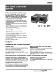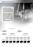
1
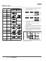
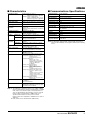
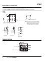
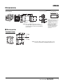
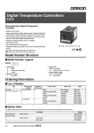
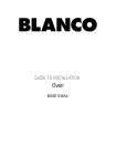
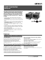
Limit Controller
E5CN-FR
This Best-selling General-purpose 48×48-mm
Temperature Controller Is Now Even Better
with the Addition of Limit Controller Models
Delivering Complete Functionality for Limit
Outputs and Easy Settings with 11-segment
Display.
• Connect to either of three options with the same model:
Infrared temperature sensor, thermocouple, or platinum resistance thermometer.
• Reset limit outputs using event inputs (models that support event
inputs).
• Communications functions are now provided for Modbus (RTU)
or CompoWay/F communications protocols (models with
communications functions).
• Water-resistant construction (NEMA4X for indoor use, equivalent to IP66).
• Conforms to FM (Factory Mutual) standards (FM3545/3810).
• Conforms to international standards including UL, CSA, and IEC
safety standards and EMC.
• Easily see the status from a distance with PV display with
two-color switching function.
• On-board power supply option is available for ES1B Infrared
Thermosensor.
Note: Refer to Precautions on page 13.
Features
Complete Limit Controller Functionality
Trace Error Status
Check the maximum temperature during an error and the time
lapsed since the error occurred using the "limit over continuation
time" and "limit over max./min. value" measuring functions.
Reset Limit Outputs Using Event Inputs (Models
with Event Inputs)
Limit outputs can be reset using event inputs, enabling multiple limit
outputs to be reset altogether from a distance.
New Annunciator Output Warning Function
Input Error Output Function
Hazard lights and buzzers on the devices alert the user of errors
when limit over errors occur.
Alarm signals are output if a sensor disconnection or other input
error occurs, enabling application in equipment and facilities
requiring safety design.
Basic Performance and Functionality as Easy as Temperature Controllers
Make Settings Easily with 11-segment Displays
The E5CN-FR uses an 11-segment display, the same as the E5CN.
The alphabet is clearly displayed, eliminating the need to make
parameter settings while having to decipher symbols, which was an
inconvenience of previous general-purpose temperature controllers.
Easily Check Error Status Using the
Two-color Switching Display
The PV display switches colors to enable status to be easily checked
from a distance.
Multiple Inputs with a Single Controller
A single Controller supports both thermocouple and platinumresistance thermometer inputs, eliminating the need to select models
depending on the input. This contributes toward reducing the number
of service parts required as well as decreasing inventory levels.
Limit Controller
E5CN-FR
1
Model Number Structure
■ Model Number Legend
E5CN-FR@MT-500
1
2 3 4
1. Output type
FR: FM Limit output
2. Number of alarms
Blank: No alarm
2:
Two alarms
3. Option Unit
M:
Option Unit can be mounted
4. Input type
T: Thermocouple/platinum resistance thermometer (multi-input)
E53-CN-@N
1
1. Functions
03:
Communications
B:
Two Event inputs
PB:
Power supply and two event inputs
Note: Other Option Boards are not supported.
This data sheet is provided as a guideline for selecting products. Be sure to refer to the following user manuals for application precautions
and other information required for operation before attempting to use the product.
E5CN-FR Temperature Controller User's Manual (Cat. No. H133)
Ordering Information
■ Limit Controllers with Temperature Sensor Inputs
Size
Power supply voltage
1/16 DIN
100 to 240 VAC
48 × 48 × 78 (W × H × D)
Number of alarm points
Control outputs
Model
0
Limit output
E5CN-FRMT-500
2
Limit output
E5CN-FR2MT-500
■ Option Units
The E5CN-FR provides optional functionality when one of the following Option Units is mounted.
Functions
Model
Communications
E53-CN03N
Two event inputs
Two event inputs
E53-CNBN
External power supply for ES1B
E53-CNPBN
Note: These Option Units can be used for the new E5CN models/E5CN-FR models only.
.
E53-CN03N
Communications
B
E53-CNBN
Event inputs
11
E53-CNPBN
Event inputs/
External power
supply for ES1B
11
11
RS-485
A
12
Do not
13
use.
Do not
14
use.
Do not
15
use.
EV1
EV2
12
13
Do not
14
use.
Do not
15
use.
EV1
EV2
Limit Controller E5CN-FR
13
+
14
External power
15
−
12 VDC±10%
20 mA
Attach the appropriate terminal labels.
2
12
Specifications
■ Ratings
Item
Power supply
voltage
100 to 240 VAC, 50/60 Hz
Operating voltage range
85% to 110% of rated supply voltage
Power consumption
7.5 VA max.
Sensor input
Models with temperature inputs
Thermocouple: K, J, T, E, L, U, N, R, S, or B
Platinum resistance thermometer: Pt100 or JPt100
Infrared temperature sensor: 10 to 70°C, 60 to 120°C, 115 to 165°C, or 160 to 260°C
Control output FM Limit output
relay
SPST-NO, 250 VAC, 3 A (resistive load), electrical life: 100,000 operations,
minimum applicable load: 5 V, 10 mA
Alarm output
SPST-NO, 250 VAC, 1 A (resistive load), electrical life: 100,000 operations,
minimum applicable load: 1 V, 1 mA
Event input
ON: 1 kΩ max., OFF: 100 kΩ min.
Contact input
Non-contact input ON: Residual voltage: 1.5 V max., OFF: Leakage current: 0.1 mA max.
Outflow current: Approx. 7 mA per point
External power supply for ES1B
12 VDC ±10%, 20 mA, Short-circuit protection provided.
Setting method
Digital setting using front panel keys
Indication method
11-segment digital display and individual indicators
Character height: PV: 11 mm, SV: 6.5 mm
Other functions
•
•
•
•
•
•
•
•
Ambient operating temperature
−10 to 55°C (with no icing or condensation), for 3-year warranty: −10 to 50°C
Limit over continuation time measurement function
Limit over max./min. value measurement function
Annunciator output
Input error output
PV display two-color switching function
Input digital filter
Input compensation
Protection functions
Ambient operating humidity
25% to 85%
Storage temperature
−25 to 65°C (with no icing or condensation)
■ Input Ranges
Thermocouples/Platinum Resistance Thermometers
Platinum resistance
thermometer
Pt100
JPt100
Input Type
Temperature range (ºF)
Name
3200
3000
2300
1500
1400
1300
1200
1100
1000
900
800
700
600
500
400
300
200
100
0
−100.0
−200.0
−300.0
Setting number
Infrared temperature
sensor
Thermocouple
K
J
T
E
L
U
N
R
S
3000
3000
B
10 to
70ºC
60 to 115 to
120ºC 165ºC
160 to
260ºC
3200
2300
2300
1500
1500
1500
1100
900.0
900.0
900.0
750.0
700
700
700
700
500
240
210.0
210.0
0.0
0.0
300
0.0
0
0.0
0
−300
1
2
3
4
The applicable standards for the input types
are as follows:
K, J, T, E, N, R, S, B: IEC584-1
L: Fe-CuNi, DIN 43710-1985
5
7
16
17
0
0
0
8
9
19
20
21
22
−300
−300
−300
6
0
−199.9
−199.9
−199.9
−199.9
0
190
−100
−100
−300
0
320
10
11
U: Cu-CuNi, DIN 43710-1985
12
13
14
15
18
Shaded settings are the default settings.
Pt100: IEC 751
Limit Controller
E5CN-FR
3
■ Alarm Types
Select alarm types out of the 12 alarm types listed in the following table.
Set value
Alarm type
Alarm output operation
When X is
positive
0
Alarm function Output OFF
OFF
1
Upper- and
(See note 1.) lower-limit
(deviation)
Upper limit
(deviation)
ON
OFF
3
Lower limit
(deviation)
ON
OFF
4
Upper- and
(See note 1.) lower-limit
range
(deviation)
L
ON
OFF
2
H
SP
X
7
8
9
10
L
11
ON
OFF
Lower-limit
with standby
sequence
(deviation)
ON
OFF
Absolute-value
upper-limit
ON
OFF
Absolute-value
lower-limit
ON
OFF
Absolute-value
lower-limit with
standby
sequence
12
Annunciator
(See note 6.) output
4
X
SP
X
0
X
0
ON
OFF
ON
OFF
H<0, L>0
|H| ≥ |L|
L SP
H
L
Case 1
H>0, L<0
|H| ≤ |L|
Case 3 (Always ON)
Case 2
H<0, L<0
SP
(See note 4.)
ON
OFF
L
X
L
H SP
H<0, L>0
|H| < |L|
ON
OFF
H>0, L<0
|H| > |L|
SP
3. Set value: 4, Upper- and lower-limit range
SP
H
X
H
SP L H
SP H
SP
SP
H SP
X
(See note 3.)
Upper-limit
with standby
sequence
(deviation)
Absolute-value
upper-limit with
standby
sequence
ON
OFF
ON
OFF
SP
Case 3 (Always ON)
H<0, L<0
L
(See note 2.)
H<0, L>0
|H| < |L|
X
ON
OFF
Case 2
Case 1
SP
Upper- and
5
L H
(See note 1.) lower-limit with ON
OFF
standby
SP
sequence
(See note 5.)
(deviation)
6
When X is
negative
Note: 1. With set values 1, 4 and 5, the upper and lower limit values
can be set independently for each alarm type, and are
expressed as “L” and “H.”
2. Set value: 1, Upper- and lower-limit alarm
X
SP
X
SP
X
SP L
H
H
H>0, L<0
|H| > |L|
H
SP
L
L SP
SP H L
H<0, L>0
|H| ≥ |L|
H>0, L<0
|H| ≤ |L|
4. Set value: 5, Upper- and lower-limit with standby sequence
For Upper- and Lower-Limit Alarm Described Above
• Case 1 and 2
Always OFF when the upper-limit and lower-limit
hysteresis overlaps.
• Case 3: Always OFF
5. Set value: 5, Upper- and lower-limit with standby sequence
Always OFF when the upper-limit and lower-limit hysteresis
overlaps.
6. The annunciator output turns ON to inform users when a
limit over occurs. This function is enabled by selecting 12
(annunciator output) for alarm 1 type. The annunciator
output turns ON when a limit over occurs, and turns OFF for
the RESET operation.
0
X
High limit
0
Limiter
Hysteresis
ON
OFF
ON
OFF
X
0
X
0
ON
OFF
ON
OFF
---
Limit Controller E5CN-FR
X
0
ON
Annunciator
output
OFF
X
0
Status of FM ON
output
OFF
(1) RESET (2) RESET
(3) RESET
Set the alarm types for alarms 1 and 2 independently in the initial
setting level. The default setting is 12 (annunciator) for alarm 1 type
and 2 (upper limit) for alarm 2 type.
■ Characteristics
■ Communications Specifications
Indication accuracy
Thermocouple: (See note 1.)
(±0.5% of indicated value or ±1°C,
whichever is greater) ±1 digit max.
Platinum resistance thermometer:
(±0.5% of indicated value or ±1°C,
whichever is greater) ±1 digit max.
Transmission line
RS-485 multipoint
connection method
Hysteresis
Alarm setting range
Communications
RS-485 (two-wire, half duplex)
Synchronization
method
Start-stop synchronization
0.1°C (°F) to 999.9°C (°F) in units of 0.1°C (°F)
Baud rate
1200, 2400, 4800, 9600, 19200, or 38400 bps
−1999 to 9999 (decimal point position depends
on input type)
Transmission code
ASCII
Data bit length
7 or 8 bits
Stop bit length
1 or 2 bits
Error detection
Vertical parity (none, even, odd)
Block check character (BCC) with CompoWay/F or
CRC-16 Modbus
Sampling period
250 ms
Affect of signal source
resistance
Thermocouple: 0.1°C/Ω max. (100 Ω max.)
(See note 4.)
Platinum resistance thermometer: 0.4°C/Ω max.
(10 Ω max.)
Insulation resistance
20 MΩ min. (at 500 VDC)
Flow control
None
2,000 VAC, 50 or 60 Hz for 1 min (between
terminals with different charge)
Interface
RS-485
Retry function
None
Malfunction
10 to 55 Hz, 20 m/s2 for 10 min each in X, Y, and
Z directions
Communications
buffer
40 bytes
Destruction
10 to 55 Hz, 0.75-mm single amplitude for 2 hrs
each in X, Y, and Z directions
Communications
response wait time
0 to 99 ms
Default: 20 ms
Malfunction
100 m/s2 min., 3 times each in X, Y, and Z
directions
Destruction
300 m/s2 min., 3 times each in X, Y, and Z
directions
Dielectric strength
Vibration
resistance
Shock
resistance
Weight
Controller: Approx. 150 g,
Mounting Bracket: Approx. 10 g
Degree of protection
Front panel: NEMA4X for indoor use
(equivalent to IP66)
Rear case: IP20, Terminal section: IP00
Memory protection
Non-volatile memory (number of writes:
1,000,000 operations)
EMC
Emission Enclosure: EN55011 Group1 ClassA
Emission AC Mains: EN55011 Group1 ClassA
Immunity ESD: EN61000-4-2 4 kV contact
discharge (level 2)
8 kV air discharge (level 3)
Immunity RF-interference:
EN61000-4-3 10 V/m
(80-1000 MHz, 1.4-2.0 GHz
amplitude modulated) (level 3)
10 V/m (900 MHz pulse
modulated)
Immunity Conducted Disturbance:
EN61000-4-6 3 V
(0.15 to 80 MHz) (level 2)
Immunity Burst: EN61000-4-4 2 kV Power-line
(level 3)
1 kV I/O signal-line (level 3)
Immunity Surge: EN61000-4-5 1kV line to line
Power line, output line (relay
output)
2 kV line to ground Power line,
output line (relay output)
1 kV line to ground Input line
(communication)
Immunity Voltage Dip/Interrupting:
EN61000-4-11 0.5 cycle, 100%
(rated voltage)
Approved standards
FM-3545/3810
UL 61010C-1
CSA C22.2 No.1010.1
Conformed standards
EN61326, EN61010-1, IEC61010-1
VDE0106 Part 100 (Finger protection), when
the terminal cover is mounted.
Note: The baud rate, data bit length, stop bit length, and vertical
parity can be individually set using the Communications Setting
Level.
Note: 1. The indication of K thermocouples in the −200 to 1300°C
range, T and N thermocouples at a temperature of −100°C
max., and U and L thermocouples at any temperature is
±2°C ±1 digit maximum. The indication accuracy of the B
thermocouple at a temperature of 400°C max. is not
specified. The indication accuracy of the R and S
thermocouples at a temperature of 200°C max. is ±3°C ±1
digit max.
2. B, R, and S sensors: 0.2°C/Ω max. (100 Ω max.)
Limit Controller
E5CN-FR
5
External Connections
• Standard insulation is applied between any of the following: power supply terminals, input terminals, output terminals, and communications
terminals (for models with communications). If reinforced insulation is required, provide additional insulation, such as spacial distance or
material insulation, as defined by IEC 60664 suitable for the maximum operating voltage.
• Consult with your OMRON representative before using the external power supply for the ES1B for any other purpose.
E5CN-FR
Limit Output
(Relay)
Alarm Outputs
1
1
11
6
6
2
12
7
7
3
13
8
8
4
14
9
2
A
−
B
Alarm 2
Input power supply 100 to 240 VAC
B
+
Pt
5
Alarm 1/
Input error output (See note.)
10
15
TC
Note: Output when an input error output is enabled in
the Advance Function Setting Level. If an input
error output is enabled, the alm1 operation
indication on the front panel will not light and
s.err will be displayed on the No. 1 display.
Platinum
Infrared
resistance temperature
thermometer
sensor
B
11
11
11
12
12
Event input 1
13
Event input 2
+
14
External power
15
−
12 VDC±10%
20 mA
RS-485
12
Event input 1
13
Event input 2
Do not use. 14
Do not use. 13
Do not use. 15
Do not use. 15
Event inputs
A
Do not use. 14
Communications
Event inputs/
External power
supply for ES1B
Nomenclature
E5CN-FR
Temperature unit
No.1 display
Operation indicators
No. 2 display
Level Key and Reset key
Up Key
RESET
LIMIT E5CN
Mode Key
6
Limit Controller E5CN-FR
Down Key
Dimensions
E5CN -FR
Terminal Models
Panel Cutout
Group Mounted
Mounted Separately
(48 × number of units −2.5) +1.0
0
6
@48
91
78
45 +0.6
0
44.8 × 44.8 48.8
58
Group mounting does not
allow waterproofing.
60 min.
45 +0.6
0
Mounting Adapter
(Accessory)
Terminal Cover
(E53-COV10)
45 +0.6
0
Note: The terminal block cannot be removed.
The suffix “-500” is added to the model number
of each Controller provided with a E53-COV10
Terminal Cover.
• Recommended panel thickness is 1 to
5 mm.
• Group mounting is not possible in the
vertical direction. (Maintain the
specified mounting space between
Controllers.)
• To mount the Controller so that it is
waterproof, insert the waterproof
packing onto the Controller.
• When two or more Controllers are
mounted, make sure that the
surrounding temperature does not
exceed the allowable operating
temperature specified in the
specifications.
■ Accessories
Terminal Cover
48
E53-COV10
48.8
22
Note: The suffix “-500” is added to the model number of each
Controller provided with a E53-COV10 Terminal Cover.
9.1
Limit Controller
E5CN-FR
7
Operating Method
■ Outline of Operation Procedures
The following diagram illustrates the entire setting level. A password is required to enter the advance function setting level and the calibration level.
Some parameters may not be displayed depending on the protection settings and operation conditions.
The control operation will stop when switching from operation level to initial setting level.
]
Power ON
Operation Level
Press the
Level + Mode Keys;
display will flash.
F
Adjustment Level
Press the
Level Key
less than 1 s.
Press the Level Key
for at least 1 s;
display will flash.
25
100
Press the
Level + Mode
Keys.
for at least 1 s
Press the Level +
Mode Keys for at least
3 s. (See note 3.)
Press the
Level Key for
at least 1 s.
F
l.adj
Press the Level
Key for at least
3 s.
Control stops.
(See
note 1.)
Protect Level
Communications
Setting Level
Initial Setting Level
Press the Level Key
for less than 1 s.
Press the Level
Key for at least 1 s.
Input password.
Set value −169
Advanced Function
Setting Level
Control in progress
Input password.
Control stopped
Set value 1201
(See
note 2.)
Not displayed for some models
Level change
Calibration Level
Note: 1. Operation level entered for software reset.
2. You cannot move to other levels by operating the keys on the front panel from the calibration level. You must turn OFF the power supply.
3. The time taken to move to the protect level can be adjusted by changing the “Move to protect level time” setting.
Troubleshooting
When an error has occurred, the No. 1 display shows the error code. Take necessary measure according to the error code, referring the table
bellow.
No. 1 display
Meaning
Action
Status at error
Limit outputs
Alarm
s.err
Input error (See note 2.)
(broken line, A/D converter
error)
Check the wiring of inputs, disconnections, shorts and input type.
(See note 3.)
OFF
-lo-
Over lower-limit indication
range (See note 2.)
Input value is smaller than control range.
Check the control range.
Upper limiter
Over upper-limit indication
range (See note 2.)
Input value is larger than control range.
Check the control range.
Upper limiter
e111
Memory error
Turn the power OFF then back ON again. If the display remains the OFF
same, the controller must be repaired. (See note 3.)
OFF
[[[[
Over display range (lowerlimit display range)
(See note 2.)
This is not an error. This is displayed when the input value exceeds
the display limit but is within the control range.
Normal operation
-hi-
Lower limiter
Lower limiter
Normal operation
Operates as
above the upper
limit.
Normal operation Operates as
above the lower
OFF
limit.
OFF
Operates as
above the upper
Normal operation limit.
Note: 1. Refer to “E5CN-FR Limit Controller User’s Manual” for details of the control range.
2. These errors are displayed only when the PV/Limit SP is displayed.
3. If the display is restored to normal after cycling the power supply, the error may have been caused by noise. Check for noise being generated nearby.
8
Limit Controller E5CN-FR
■ Parameters
Some parameters are not displayed
depending on the model of the Controller
and parameter settings. For details, refer
to the E5CN-FR Limit Controller User's
Manual (Cat. No. H133).
Power ON
Press the Level
+ Mode Keys
for at least 1 s.
Operation Level
Protect Level
∗
Press the Level + Mode
Keys for at least 3 s.>*
*The time taken to move to protect
level can be adjusted bychanging the
"Move to protect level time" setting.
pmov
Move to protect
level
0
M
oapt
icpt
Initial Setting/Communications
protection
1
M
wtpt
∗
Input password
(Displayed when
password is set.)
Operation/adjustment
protection
0
M
Setting change protection
0
M
Adjustment Level
Press the Level Key for
less than 1 s.
Monitor only
F
25
PV/Limit setting
value
sp
Limit setting
value
100
M
F
100
M
time
Set either of these
parameters.
Change using the SP
display change setting.
Limit over continuation
time
Password to
move to protect
level
Password setting
(always displayed)
F
M
sp-s
al-1
0
M
F
al1h
0
M
Set either of these
parameters.
Limit over min.
p-lo value
----
Adjustment
level display
Displayed one time when
moving to adjustment level.
M
F
F
Limit over max.
---M
ladj
Limit set value
100
M
---M
F
Press the Level Key for
at least 1 s.
∗
p-hi value
off
M
prlp
Press the Level Key for
at least 3 s.
Press the Level Key for
less than 1 s.
F
al1l
0
M
F
al-2
0
M
F
al2h
0
M
F
al2l
Alarm value 1
Upper-limit
alarm value 1
Set either of these
parameters.
Lower-limit
alarm value 1
Alarm value 2
Upper-limit
alarm value 2
Set either of these
parameters.
Lower-limit
alarm value 2
0
M
F
ins
0.0
M
F
insh
0.0
M
F
insl
0.0
M
F
hys
1.0
M
cmwt
Temperature
input shift
1-point shift
Upper-limit
temperature input
Set either of these
parameters.
2-point shift
Lower-limit
temperature input
Hysteresis
Communications writing
off
M
Limit Controller
E5CN-FR
9
Press the Level Key for
less than 1 s.
Initial Setting Level
∗
in-t
Press the Level Key
for less than 1 s.
Communications Level
(only models with communications.)
Changes are effective after cycling power
or after a software reset.
∗
Input type
cwf
M
5
M
d-u
Temperature unit
u-no
Selecting upper
and lower limit
bps
9.6
M
hi
M
∗
∗
alt1
Alarm 1 type
alt2
Alarm 2 type
len
Communications unit No.
Communications baud rate
Communications
data length
CompoWay/F
only
7
M
2
M
sbit
Communications
stop bits
2
M
2
M
amov
Protocol selection
Switches between
Compoway/F and
Modbus.
1
M
c
M
l-hl
psel
Move to advanced
function level
prty
0
∗
Communications parity
even
M
sdwt
Send delay
20
Press the Level Key for at least 1 s.
Advanced Function Setting Level
Move by setting password (-169).
∗
init
Parameter initialization
off
M
ev-1
Event input assignment 1
Event input assignment 2
none
M
rest
Standby sequence reset
method
a
M
al1n
alh1
Alarm 1 open in alarm
∗
alh2
Alarm 2 open in alarm
Alarm 2 hysteresis
on
M
10
Limit Controller E5CN-FR
sero
Input error output
colr
PV display change
rmd
tmsl
cmov
0
M
Input digital filter
0.0
M
pvad
Alarm 2 latch
off
M
Restart mode
Time selection
l.out
M
0.2
M
inf
a2lt
con@
M
n-o
M
F
Alarm 1 latch
off
M
red
M
Alarm 1 hysteresis
0.2
M
al2n
a1lt
off
M
n-o
M
F
Automatic return of
display mode
off
M
none
M
ev-2
ret
Additional PV display
Move to calibration level
Limit Controller Functions
When the measured temperature (PV) exceeds the limit SP, the limit output relay turns OFF and the OUT1 operation indicator turns ON. If the
limit output relay turns OFF (limit alarm is ON), the limit output relay will remain off until the operator manually resets the Limit Controller.
Before turning
ON power
Limit output relay ON
Limit output relay OFF
Temperature in furnace
Limit SP
Hysteresis
Control SP
Power ON
Malfunction
■ Selecting Upper/Lower Limit
• The upper/lower limit selection setting enables switching between upper limit and lower limit operation.
• The default setting is for upper limit operation.
Select either upper limit or lower limit.
■ Resetting Limit Outputs
• Limit outputs can be reset by pressing the Level Key/Reset Key for 1 second min. while in the operation level.
• The limit output reset operation can be used to reset limit outputs and annunciator outputs.
∗ When the limit status is OFF, the limit output is cleared and the limit output relay turns ON. When the limit status is ON (limit over status), limit
outputs will not be reset.
∗ The annunciator output turns OFF regardless of the limit status.
∗ Event inputs used as reset inputs (for resetting limit outputs) can be received while in the operation level, adjustment level, or protect level.
Hysteresis
Limit SP
Limit status
Annunciator output
Limit output relay
ON
OFF
ON
OFF
ON
OFF
(1) RESET
(2) RESET
(Reception
(Reception
not possible) possible)
(3) RESET
(Reception
not possible)
Limit Controller
E5CN-FR
11
■ Example of Typical Use
Temperature Sensor
Sensor input
Limit Sensor
Limit output
Control output
SSR
Heater
Controlled device: Furnace/oven
Temperature Controller
(e.g., E5CN)
Sensor input
E5CN-FR Limit Controller
Application examples are for reference only. In actual application, confirm the functionality and safety of all equipment in advance. In particular,
when considering an application requiring a high degree of safety, take into account all ratings, performance capacities, failsafe measures, and
other safety measures required by the application, and consult with your OMRON representative to confirm specifications and capabilities.
12
Limit Controller E5CN-FR
Precautions
!CAUTION
Do not touch the terminals while power is being supplied.
Doing so may occasionally result in minor injury due to
electric shock.
Do not allow pieces of metal, wire clippings, or fine
metallic shavings or filings from installation to enter the
product. Doing so may occasionally result in electric
shock, fire, or malfunction.
Do not use the product where subject to flammable or
explosive gas. Otherwise, minor injury from explosion
may occasionally occur.
Never disassemble, modify, or repair the product or touch
any of the internal parts. Minor electric shock, fire, or
malfunction may occasionally occur.
Caution: Risk of Fire and Electric Shock
a) This product is UL listed as Open Type Process
Control Equipment. It must be mounted in an
enclosure that does not allow fire to escape externally.
b) More than one disconnect switch may be required to
de-energize the equipment before servicing.
c) Signal inputs are SELV, limited energy.
d) Caution: To reduce the risk of fire or electric shock, do
not interconnect the outputs of different Class 2
circuits.
If the output relays are used past their rated load or life
expectancy, contact fusing or burning may occasionally
occur. Always consider the application conditions and the
inrush current, and use the output relays within their rated
load and electrical life expectancy. The life expectancy of
output relays varies considerably with the output load and
switching conditions.
Tighten the terminal screws to between 0.74 and 0.9 N·m.
Loose screws may occasionally result in fire.
Set the parameters of the product so that they are
suitable for the system. If they are not suitable,
unexpected operation may occasionally result in property
damage or accidents.
Warning: To reduce the risk of electric shock or fire, install
in a Pollution Degree 2 environment (a controlled
environment relatively free of contaminants).
A malfunction in the product may occasionally make
control operations impossible or prevent alarm outputs,
resulting in property damage to connected equipment
and machinery. To maintain safety in the event of
malfunction of the product, periodically check the Limit
Controller's operation.
Precautions for Safe Use
1. Do not use this product in the following places:
• Places directly subject to heat radiated from heating equipment.
• Places subject to splashing liquid or oil atmosphere.
• Places subject to direct sunlight.
• Places subject to dust or corrosive gas (in particular, sulfide gas
and ammonia gas).
• Places subject to intense temperature change.
• Places subject to icing and condensation.
• Places subject to vibration and large shocks.
2. Use and store within the rated temperature and humidity ranges.
Provide forced-cooling if required.
3. To allow heat to escape, do not block the area around the
product. Do not block the ventilation holes on the product.
4. Be sure to wire properly with correct polarity of terminals.
5. Use specified size (M3.5, width 7.2 mm or less) crimped
terminals for wiring. Use wires with a gage of AWG24 to AWG14
(equal to cross-sectional areas of 0.205 to 2.081 mm2). (The
stripping length is 5 to 6 mm.).
6. Do not wire the terminals that are not used.
7. Allow as much space as possible between the product and
devices that generate a powerful high-frequency or surge.
Separate the high-voltage or large-current power lines from other
lines, and avoid parallel or common wiring with the power lines
when you are wiring to the terminals.
8. Use this product within the rated load and power supply.
9. Make sure that the rated voltage is attained within two seconds
of turning the power ON.
10. Make sure the product has 30 minutes or more for warm up.
11. A switch or circuit breaker must be provided close to the product.
The switch or circuit breaker must be within easy reach of the
operator, and must be marked as a disconnecting means for this
unit.
12. Always turn OFF the power supply before pulling out the interior
of the product, and never touch nor apply shock to the terminals
or electronic components. When inserting the interior of the
product, do not allow the electronic components to touch the
case.
13. Do not use paint thinner or similar chemical to clean with. Use
standard grade alcohol.
14. Design the system (e.g., control panel) considering the 2
seconds of delay that the product's output to be set after power
ON.
15. The output may turn OFF when shifting to certain levels. Take
this into consideration when performing control.
16. Refer to the instruction sheet for installing Option Unit (E53CN03N/E53-CNBN/E53-CNPBN).
Limit Controller
E5CN-FR
13
Precautions for Correct Use
Service Life
Mounting to a Panel
1. Use the Limit Controller within the following temperature and
humidity ranges:
Temperature: −10 to 55°C (with no icing or condensation)
Humidity: 25% to 85%
If the Controller is installed inside a control board, the ambient
temperature must be kept to under 55°C, including the
temperature around the Controller.
2. The service life of electronic devices like Limit Controllers is
determined not only by the number of times the relay is switched
but also by the service life of internal electronic components.
Component service life is affected by the ambient temperature:
the higher the temperature, the shorter the service life and, the
lower the temperature, the longer the service life. Therefore, the
service life can be extended by lowering the temperature of the
Limit Controller.
3. When two or more Limit Controllers are mounted horizontally
close to each other or vertically next to one another, the internal
temperature will increase due to heat radiated by the Limit
Controllers and the service life will decrease. In such a case, use
forced cooling by fans or other means of air ventilation to cool
down the Limit Controllers. When providing forced cooling,
however, be careful not to cool down the terminals sections alone
to avoid measurement errors.
1. To mount the Controller so that it is waterproof, insert the
waterproof packing onto the Controller. Group mounting does not
allow waterproofing. The waterproof packing is not required if
waterproof is not necessary.
2. Insert the E5CN-FR into the mounting hole in the panel.
3. Push the adapter along the Controller body from the terminals up
to the panel, and fasten it temporarily.
4. Tighten the two fixing screws on the adapter. Alternately tighten
the two screws a little at time to keep them balanced. Tighten
them to a torque of 0.29 to 0.39 N·m.
Attaching the Terminal Cover
Make sure that the “UP” letters on the E5CN-FR are at the top and
insert the terminal cover into the holes at the top and bottom of the
Controller.
Removing the Controller from the Case
When carrying out maintenance on the Controller, the Controller can
be removed from the case leaving the terminal leads attached. The
Controller can be removed from the case only with the E5CN-FR.
Tool insertion hole
Flat-blade screwdriver
(Unit: mm)
Measurement Accuracy
Waterproofing
The degree of protection is as shown below. Sections without any
specification on their degree of protection or those with IP@0 are not
waterproof.
Front panel: NEMA4X for indoor use (equivalent to IP66)
Rear case: IP20, Terminal section: IP00
Operating Precautions
(1)
20 min.
ALM1
ALM2
ALM3
HA
PV
OUT1
(3)
OUT2
STOP
CMW
MANU
(2)
(1)
E5 C
N
1. Insert the tool into the slots (one on the top and one on the
bottom) and release the hooks.
2. Insert the tool into the gap between the front panel and rear case
and pull out the front panel slightly. Hold both sides of the front
panel and draw out the Controller towards you. Do not apply
unnecessary force.
3. Before inserting the Controller, confirm that the sealing rubber is
in place. Insert the Controller into the rear case until you hear a
click. Press on the hooks on the top and bottom of the rear case
to be sure that the hooks are securely locked in place.Be sure
that electronic parts do not come in contact with the case.
Wiring Precautions
1. It takes approximately two seconds for the outputs to turn ON
from after the power supply is turned ON. Due consideration must
be given to this time when incorporating Limit Controllers in a
sequence circuit.
2. Avoid using the Controller in places near a radio, television set, or
wireless installing. These devices can cause radio disturbances
which adversely affect the performance of the Controller.
Mounting
Terminal Cover
(order separately)
Mounting Adapter
(Accessory)
• Separate input leads and power lines to protect the Controller and
its lines from external noise.
• Use wires of a thickness of AWG24 (0.205 mm2) to AWG14
(2.081 mm2).
The exposed current-carrying part to be inserted into terminals
must be 5 to 6 mm.
• We recommend using crimp terminals when wiring the terminals.
• Tighten terminal screws to a torque of 0.74 to 0.90 N·m.
• Use the following type of crimp terminals for M3.5 screws.
7.2 mm min.
7.2 mm min.
Waterproof packing
Panel
14
2.0
SV
0.4
1. When extending or connecting the thermocouple lead wire, be
sure to use compensating wires that match the thermocouple
types.
2. When extending or connecting the lead wire of the platinum
resistance thermometer, be sure to use wires that have low
resistance and keep the resistance of the three lead wires the
same.
3. Mount the Limit Controller so that it is horizontally level.
4. If the measurement accuracy is low, check to see if input shift has
been set correctly.
E5CN-FR
Limit Controller E5CN-FR
Related Product Information
■ Please use these products in combination with the Limit Controller.
Digital Temperature Controller
E5CN/E5CN-U
This Best-selling General-purpose 48 × 48-mm
Temperature Controller Is Now Better.
USB-Serial Conversion Cable and Support
Software Are Also Available.
Catalog Number:
H126
Infrared Thermosensor
ES1B
Achieve Low-cost Measurements with an Infrared
Thermosensor.
Limit Controller
Catalog Number:
H127
E5CN-FR
15
Warranty and Application Considerations
Read and Understand this Catalog
Please read and understand this catalog before purchasing the products. Please consult your OMRON representative if you
have any questions or comments.
Warranty and Limitations of Liability
WARRANTY
OMRON's exclusive warranty is that the products are free from defects in materials and workmanship for a period of one year (or
other period if specified) from date of sale by OMRON.
OMRON MAKES NO WARRANTY OR REPRESENTATION, EXPRESS OR IMPLIED, REGARDING NON-INFRINGEMENT,
MERCHANTABILITY, OR FITNESS FOR PARTICULAR PURPOSE OF THE PRODUCTS. ANY BUYER OR USER
ACKNOWLEDGES THAT THE BUYER OR USER ALONE HAS DETERMINED THAT THE PRODUCTS WILL SUITABLY MEET
THE REQUIREMENTS OF THEIR INTENDED USE. OMRON DISCLAIMS ALL OTHER WARRANTIES, EXPRESS OR
IMPLIED.
LIMITATIONS OF LIABILITY
OMRON SHALL NOT BE RESPONSIBLE FOR SPECIAL, INDIRECT, OR CONSEQUENTIAL DAMAGES, LOSS OF PROFITS,
OR COMMERCIAL LOSS IN ANY WAY CONNECTED WITH THE PRODUCTS, WHETHER SUCH CLAIM IS BASED ON
CONTRACT, WARRANTY, NEGLIGENCE, OR STRICT LIABILITY.
In no event shall the responsibility of OMRON for any act exceed the individual price of the product on which liability is asserted.
IN NO EVENT SHALL OMRON BE RESPONSIBLE FOR WARRANTY, REPAIR, OR OTHER CLAIMS REGARDING THE
PRODUCTS UNLESS OMRON'S ANALYSIS CONFIRMS THAT THE PRODUCTS WERE PROPERLY HANDLED, STORED,
INSTALLED, AND MAINTAINED AND NOT SUBJECT TO CONTAMINATION, ABUSE, MISUSE, OR INAPPROPRIATE
MODIFICATION OR REPAIR.
Application Considerations
SUITABILITY FOR USE
OMRON shall not be responsible for conformity with any standards, codes, or regulations that apply to the combination of
products in the customer's application or use of the products.
Take all necessary steps to determine the suitability of the product for the systems, machines, and equipment with which it will
be used.
Know and observe all prohibitions of use applicable to this product.
NEVER USE THE PRODUCTS FOR AN APPLICATION INVOLVING SERIOUS RISK TO LIFE OR PROPERTY WITHOUT
ENSURING THAT THE SYSTEM AS A WHOLE HAS BEEN DESIGNED TO ADDRESS THE RISKS, AND THAT THE OMRON
PRODUCTS ARE PROPERLY RATED AND INSTALLED FOR THE INTENDED USE WITHIN THE OVERALL EQUIPMENT OR
SYSTEM.
Disclaimers
PERFORMANCE DATA
Performance data given in this catalog is provided as a guide for the user in determining suitability and does not constitute a
warranty. It may represent the result of OMRON's test conditions, and the users must correlate it to actual application
requirements. Actual performance is subject to the OMRON Warranty and Limitations of Liability.
CHANGE IN SPECIFICATIONS
Product specifications and accessories may be changed at any time based on improvements and other reasons. Consult with
your OMRON representative at any time to confirm actual specifications of purchased product.
DIMENSIONS AND WEIGHTS
Dimensions and weights are nominal and are not to be used for manufacturing purposes, even when tolerances are shown.
ALL DIMENSIONS SHOWN ARE IN MILLIMETERS.
To convert millimeters into inches, multiply by 0.03937. To convert grams into ounces, multiply by 0.03527.
Cat. No. H132-E1-01
In the interest of product improvement, specifications are subject to change without notice.
OMRON Corporation
Industrial Automation Company
Industrial Devices and Components Division H.Q.
Measuring Components Department
Shiokoji Horikawa, Shimogyo-ku,
Kyoto, 600-8530 Japan
Tel: (81)75-344-7080/Fax: (81)75-344-7189
16
Printed in Japan
1004-1M (1004) (O)