1
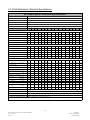
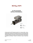
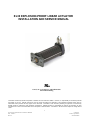
EL30 EXPLOSION-PROOF LINEAR ACTUATOR
INSTALLATION AND SERVICE MANUAL
Class I, div 1, Groups B, C and D Hazardous
Environment Rating
Information furnished by EXLAR Corporation is believed to be accurate and reliable. However, no responsibility is assumed by EXLAR
Corporation for its use. EXLAR reserves the right to change the design and operation of the equipment described herein and any
associated motion products that may appear in this document. Information in this document pertaining to equipment not furnished by
EXLAR should be confirmed by that equipment manufacturer. EXLAR assumes no responsibility for changes to information by other
manufacturers or errors in that information or the description of that information. Information in this document is subject to change without
notice.
1
EL Series Explosion-Proof Actuator Manual
PN: 23942
Rev D
6/14/2011
Exlar Corporation
952-500-6200
TABLE OF CONTENTS
1.0 Introduction
1.1 Warranty and Limitations of Liability
1.2 Safety Considerations
1.3 Explosion-Proof Ratings
2.0 System Configuration
2.1 Typical System Configuration
2.2 Typical System Wiring
2.3 Standard Actuator Pin-outs and Connections
2.4 Feedback Information
3.0 Installation and Operation
3.1 Lubrication Requirements
3.2 Grease Lubrication
3.5 Mounting Configurations
3.6 Mounting Considerations
3.7 General Operation
4.0 Maintenance Procedures
4.1 Disassembly
4.2 Lubrication Maintenance
4.3 Reassembly
4.4 Seal Maintenance
5.0 Specifications
5.1 EL Series Performance Specifications
5.2 EL Series Mechanical and Electrical Specifications
6.0 Troubleshooting Procedures
7.0 Installation
7.1 Exlar SV Series with EL30 Linear Actuator
2
EL Series Explosion-Proof Actuator Manual
PN: 23942
Rev D
6/14/2011
Exlar Corporation
952-500-6200
1.0 INTRODUCTION
1.1 Warranty and Limitation of Liability
EXLAR warrants its product(s) to the original purchaser and in the case of original equipment manufacturers,
to their original customer to be free from defect in material and workmanship and to be made in accordance
with Exlar’s specifications for the product(s) as published at the time of purchase unless otherwise agreed to
in writing by an authorized Exlar representative. In no event shall EXLAR be liable or have any
responsibility under such warranty if the products have been improperly stored, installed, used or maintained,
or if Buyer has permitted any unauthorized modifications, adjustments and/or repairs to such product(s).
Seller's obligation hereunder is limited solely to repairing or replacing (at its option), at the factory, any
product(s), or parts thereof, which prove to Seller's satisfaction to be defective materials or workmanship, and
within the period of time in accordance with the seller's stated product warranty (see terms and conditions),
however, that written notice of claimed defects shall have been given to EXLAR within 30 days from the date
any such defect is first discovered. The product(s) or part(s) claimed to be defective must be returned to
EXLAR, transportation prepaid by Buyer, with written specification of the claimed defect.
Components such as seals, wipers, bearings, bushings, splines and roller screw components are considered
wear parts and must be inspected and serviced on a regular basis. Any damage caused by failure to properly
lubricate EXLAR products and/or to replace wear parts at appropriate times is not covered by this warranty.
THE FOREGOING WARRANTY IS IN LIEU OF ALL OTHER WARRANTIES (EXCEPT AS TITLE),
WHETHER EXPRESSED OR IMPLIED, INCLUDING WITHOUT LIMITATION, ANY WARRANTY OF
MERCHANTABILITY, OR OF FITNESS FOR ANY PARTICULAR PURPOSE, OTHER THAN AS
EXPRESSLY SET FORTH AND TO THE EXTENT SPECIFIED HEREIN, AND IS IN LIEU OF ALL
OTHER OBLIGATIONS OR LIABILITIES ON THE PART OF EXLAR.
SELLER'S MAXIMUM LIABILITY WITH RESPECT TO THESE TERMS AND CONDITIONS AND
ANY RESULTING SALE, ARISING FROM ANY CAUSE WHATSOEVER, INCLUDING WITHOUT
LIMITATION, BREACH OF CONTRACT OR NEGLIGENCE, SHALL NOT EXCEED THE PRICE
SPECIFIED HEREIN OF THE PRODUCT(S), GIVING RISE TO THE CLAIM, AND IN NO EVENT
SHALL EXLAR BE LIABLE UNDER THE TERMS OF THE WARRANTY OTHERWISE FOR SPECIAL,
INCIDENTAL OR CONSEQUENTIAL LOSSES RESULTING FROM INABILITY TO USE THE
PRODUCT(S), INCREASED OPERATING COST, LOSS OF PRODUCTION, LOSS OF SPECIAL
INCIDENTAL OR CONSEQUENTIAL DAMAGES, WHETHER SIMILAR OR DISSIMILAR OF ANY
NATURE ARISING OR RESULTING FROM THE PURCHASE, INSTALLATION, REMOVAL, REPAIR,
OPERATION, USE OR BREAKDOWN OF THE PRODUCT(S), OR ANY OTHER CAUSE
WHATSOEVER INCLUDING NEGLIGENCE.
The foregoing warranty shall apply to products or parts that have been repaired or replaced pursuant to such
warranty, and within the period of time, in accordance with the Seller's stated warranty.
No person including any agent of EXLAR, is authorized to make any representation of warranty on behalf of
EXLAR concerning any products manufactured by EXLAR, except to refer to this warranty.
3
EL Series Explosion-Proof Actuator Manual
PN: 23942
Rev D
6/14/2011
Exlar Corporation
952-500-6200
1.2 Safety Considerations
As with any electro-mechanical device, safety should be considered during the installation and
operation of your EL Series actuator. Throughout this manual you will see paragraphs marked
with CAUTION and WARNING signs as shown below.
CAUTION
WARNING
Pay particular attention to these paragraphs. They are intended to provide you with helpful
information to ensure safe and trouble-free installation.
1.3 Explosion-Proof Ratings
EL Series actuators are rated for Class 1, div 1, Groups B, C and D. The classification of "Class 1"
means that flammable gases or vapors may be present in the air in quantities sufficient to produce
explosive or ignitable mixtures. "Division 1" means that hazardous concentrations in the air may exist
continuously, intermittently, or periodically under normal operating conditions. "Group B" allows for
atmospheres containing hydrogen, or gases (or vapors) of equivalent hazard, such as manufactured gas.
"Group C" allows for atmospheres containing ethyl-ether vapors, ethylene or cyclo propane. "Group
D" allows for atmospheres containing gasoline, hexane, naptha, benzene, butane, alcohol, acetone,
benzol, lacquer solvent vapors, or natural gas. EL Series actuators are not rated for operation in
atmospheres containing acetylene.
It is the responsibility of the user to provide for properly rated conduit connections to the EL
Series actuator. Exlar takes no system responsibility beyond the actuator ratings.
4
EL Series Explosion-Proof Actuator Manual
PN: 23942
Rev D
6/14/2011
Exlar Corporation
952-500-6200
2.0 SYSTEM CONFIGURATION
2.1 EL Series Actuator System Configuration
EL Series actuators incorporate an integral brushless servo motor. The design of this motor and selection of the
proper feedback configuration allows EL Series actuators to be powered by nearly every brand of brushless
motor amplifier on the market that powers brushless motors with resolver feedback.
The schematic below shows the typical connections for a single axis system with an EL actuator and servo
amplifier.
Each brand of brushless motor amplifiers may have unique wiring requirements, parameter settings and
operational principles that affect how the actuator operates. Details on connections can be obtained from Exlar
applications engineering.
Never attempt to connect or disconnect the actuator with power applied. Dangerous voltages
are present. Damage to equipment and injury to personnel can result. Many amplifiers have
voltage present for a considerable time period after incoming power is removed. Take care to
insure that the amplifier has discharged all power.
5
EL Series Explosion-Proof Actuator Manual
PN: 23942
Rev D
6/14/2011
Exlar Corporation
952-500-6200
Typical System Connections
6
EL Series Explosion-Proof Actuator Manual
PN: 23942
Rev D
6/14/2011
Exlar Corporation
952-500-6200
2.2 Typical System Wiring
Please refer to Section 7.0 for specific wiring information.
2.3 Standard Actuator Connections
Please refer to Section 7.0 for connection information.
2.4 Feedback Information
EL Series actuators use resolvers as their primary feedback device. Depending on the amplifier that will e used
to operate the actuator, the hookup of the actuator can vary. Always consult Section 7.0 for proper wiring, or
contact Exlar for the correct wiring details.
The EL Series actuators incorporate a 2 pole resolver as the primary rotary feedback device. The selection of
this feedback device is dictated by the amplifier that the end user will use to operate the actuator. This amplifier
is indicated in the model number of the EL Series actuator as a 3 digit code consisting of 2 letters and 1 number.
Each amplifier has specific requirements for the feedback on the motor. Not all resolver-based amplifiers can
use the same resolver, resolver alignment, or relative direction of resolver rotation.
Many amplifiers offer software that allows the entering of parameters or the downloading of "motor data files"
that dictate how the feedback must be set up on the motor. Exlar can provide many of these "data files" or the
proper parameters to enter. Entering motor parameter data to some amplifiers may require assistance from the
amplifier manufacturer.
Feedback Alignment
When Exlar manufactures an EL Series actuator, the feedback is mounted, aligned and test run on the amplifier
that the customer plans to use, or one that is known to be equivalent for confirming proper feedback alignment
and operation. In any case where it is determined that the feedback has become mis-aligned, or an amplifier
change is made requiring the feedback to be aligned differently, it is recommended that Exlar be contacted and
arrangements made to have that procedure performed.
Feedback Wiring
The wiring of the feedback device is critical to the operation of the actuator with the selected amplifier. Miswiring the feedback cable can cause unstable operation, incorrect operation or no operation at all. In some
cases, if the proper current limits are not set in the amplifier, mis-wiring of the feedback cable can lead to
damage of the motor.
Resolvers
A resolver is a non-electronic device that works like a small transformer. When rotated, it generates two sine
waves that are out of phase with one another. By decoding these two sine waves, the amplifier can monitor the
direction, revolutions traveled and speed of rotation of the motor. Each sine wave typically represents one
revolution of the motor, so the amplifier can also use these signals to know where the motor is within that
revolution. By knowing the motor's position, the amplifier can properly time the supply of current and voltage
to the motor for it to rotate. This process is commutation. For the amplifier to properly commutate the motor,
it must have a reference, or zero, point from which to track the motor's rotation. This reference point is critical,
and is provided to the amplifier through the proper alignment of the resolver to the phases of the motor during
the actuator assembly.
7
EL Series Explosion-Proof Actuator Manual
PN: 23942
Rev D
6/14/2011
Exlar Corporation
952-500-6200
3.0 INSTALLATION AND OPERATION
3.1 Lubrication Requirements
The actuator is shipped from the factory fully greased and ready for installation. Exlar recommends using
Mobilith SHC 220, a high performance, extreme-pressure grease. The unique physical properties of the
synthetic base oil provide outstanding protection against wear, rust, corrosion and high or low-temperature
degradation. Mobilith SHC allows for very low starting and running torque values. Its operating range is minus
40 degrees C to plus 177 degrees C (-40 degrees F to +350 degrees F).
3.2 Mounting Configurations
The EL Series actuators come with a choice of mounting configurations. The standard configurations
available are Rear Clevis, Front Flange or Threaded Face. Certified drawings are available from Exlar.
General drawings are shown in the Exlar catalog.
3.3 Mounting Considerations
As with any linear actuator product, misalignment of the EL Series actuator with respect to whatever load the
actuator is being used to move is of great concern. Any misalignment will decrease the life of the
components within the actuator and also may create problems within the application associated with
misalignment. Therefore every effort should be made to minimize misalignment as much as is possible.
Excessive side load on the output rod of the actuator will dramatically reduce the life of the
actuator and should be avoided completely. Side load can be caused from misalignment or
loading that is not inline with the actuator output rod.
3.4 General Operation
The EL Series linear actuators function in the same manner as a brushless servomotor. The servo amplifier is
used to rotate the motor at controlled speed and torque, and for controlled numbers of revolutions and move
times. This rotary motion is translated into linear motion by the internal planetary roller screw mechanism of
the EL Series linear actuator.
The relationship between the rotary motion of the motor and the linear motion of the actuator corresponds to
the following relationships:
Linear Distance Traveled (in) = (Motor Revolutions)*(Roller Screw Lead)
Linear Speed (in/sec) = ((Motor RPM) / 60)*(Roller Screw Lead)
Linear Force (lbf) = ((Motor Torque (in-lbf))*(2π)*(efficiency)) / (Roller Screw Lead (in))
All of the above relationships require proper anti-rotation of the EL Series actuator rod.
8
EL Series Explosion-Proof Actuator Manual
PN: 23942
Rev D
6/14/2011
Exlar Corporation
952-500-6200
For more information on sizing and selection of EL Series actuators and servo amplifiers to power them,
consult the sizing and selection section of the Exlar catalog.
Motor RMS current must be maintained at a level below the continuous current rating of the
EL Series actuator or damage to the motor stator will result.
The peak current setting must be maintained at a level below the peak current rating of the
EL Series actuator or damage to the stator will result.
Care should be taken not to exceed the physical travel limits of EL Series Actuators. Doing
so will cause the actuator to end-crash internally. End crashes can physically damage the
roller screw and the internal components of the actuator.
9
EL Series Explosion-Proof Actuator Manual
PN: 23942
Rev D
6/14/2011
Exlar Corporation
952-500-6200
4.0 MAINTENANCE PROCEDURES
4.1 Disassembly
Refer to the exploded view on the following page.
1.) Remove the actuator assembly from the machine by disconnecting the cables, main rod coupling and
actuator mounting bolts or fasteners.
2.) If your unit does not have an external anti rotate assembly, skip this step. Loosen the two machine screws
that clamp the anti-rotate cross member to the actuator output rod. Slide the anti-rotate mechanism forward
and off the actuator.
3.) Remove the rear tie rod nuts from the back of the actuator.
Extreme care should be taken when removing the tie rod nuts or tie rods so as not to twist or
pull on the end cap of the actuator. The end cap houses the feedback device.
Alignment of this feedback device to the phases of the motor is critical to the operation of
the system. Some feedback devices are sensitive to movement of their mounting surface
once installed and can be damaged if care is not taken.
4.) If your actuator does not have a front flange, skip this step. Slide the front flange forward and off the
actuator. The tie rods will remain attached to the front flange.
4.2 Lubrication Maintenance
Grease lubricated units will require periodic inspection and renewal of the bearing and roller screw grease.
The table below shows the recommended grease renewal period.
RMS Rotational
speed(RPM)
250
500
1000
1500+
Recommended Grease Renewal Period hours)
CASE TEMP 65ºC
(149ºF)
10,000
8,500
6,000
3,500
CASE TEMP 80ºC
(176ºF)
5,000
4,250
3,000
1,750
CASE TEMP 95ºC
(203ºF)
2,500
2,125
1,500
875
Grease Renewal
The angular contact thrust bearings located in the front of the actuator, the roller screw cylinder, and the
roller screw assembly are the components that require grease. They require a coating of grease. They do
not need to be packed with grease. Excess grease only requires more torque from the motor when
returned to operation, and does not improve the lubrication of the unit.
1.) Use a brush to work approximately 0.5 in3 of grease for every 3 inches of stroke length into the roller
screw cylinder. Be sure to cover all of the threaded areas of the cylinder.
10
EL Series Explosion-Proof Actuator Manual
PN: 23942
Rev D
6/14/2011
Exlar Corporation
952-500-6200
2.) Use a brush to work grease in to the roller screw assembly. Be sure to cover all the threaded surfaces of
the screw assembly. This can be accomplished by applying grease to a few places on the roller screw
assembly and rotating the components repeatedly in both directions to work the grease into the assembly.
3.) Force grease into the front of the thrust bearing assembly. Make a concerted effort to insure that the
grease is well worked in. Grease must reach the bearing just behind the bearing that is visible as well. Use
the following amounts of grease for each size roller screw and bearing:
EL30: 0.75 in3
4.3 Reassembly
1.) Rethread the roller screw into the internally threaded cylinder (ITC). It is a multiple start screw, and this is
not always easy. DO NOT FORCE THE ROLLER SCREW INTO THE CYLINDER. It is best to have the
actuator vertical with the open end of the roller screw cylinder facing up. Position the roller screw above the
cylinder so that it is aligned axially with the ITC. Slowly turn the roller screw 1/4 to 1/2 a turn
counterclockwise with it in contact with the ITC. This will help to align the threads on the roller screw with
the threads in the ITC. Rotate the roller screw clockwise and it should begin to thread into the cylinder. If it
does not turn freely, remove it and begin again. When threading the screw into the cylinder, it will roll freely
into the actuator. When it reaches the portion of the cylinder that contains the motor magnets, the roller screw
will be more difficult to turn because of the magnetic field of the magnets. THIS IS NORMAL. Continue to
thread the roller screw into the cylinder. When it reaches the bottom, it will become difficult to turn and the
motor and bearings will begin to rotate with it. The roller screw is now fully inserted into the cylinder.
2.) Place a small amount of seal lubricant on the inside surface of the seal/bushing assembly.
3.) Replace the faceplate and case extension. Remount front flange by sliding tie rods through the holes in the
faceplate and through the holes in the rear end cap. Place the flange on the pilot diameter located on the front
of the faceplate.
4.) Replace the rear tie rod washers and nuts and tighten to the proper torque. Tighten the nuts
simultaneously by partially tightening each in an opposing corner pattern until each is torqued to the rated
value shown below.
EL30: 90 lbf-in (7.5 lbf-ft, 10.16 N-m)
11
EL Series Explosion-Proof Actuator Manual
PN: 23942
Rev D
6/14/2011
Exlar Corporation
952-500-6200
4.4 Seal Maintenance
It is recommended that at the suggested time of lubrication the main rod seal and bushing assembly (FSB) be
replaced. The main rod seal can be removed by threading it out of the face plate using a standard rod seal gland
wrench or spanner wrench. A new main rod seal can be slid over the main rod, taking care not to touch the seal
material to the threaded rod end. To have this service performed for you, contact Exlar Engineering or arrange
with Exlar Returns Department to send your unit in for service.
Standard FSB
Part Numbers
11617
EL30
Install Torque
200 lb-in (22.58 N-m)
Main Rod Seal FSB and Bushing
Note: Some actuators are provided with special FSBs due to chemical exposure or other special requirements.
Contact Exlar if there is a question about your particular actuator having a standard material FSB.
FSB Installation/Replacement:
1. Using proper sized gland or spanner wrench, remove existing FSB from actuator face plate, and slide off the
actuator rod. This will require the removal of any rod attachments. One source for gland wrenches is Martin
Fluid Power. http://www.mfpseals.com/seal_repair_kits/parker-2.shtml
Exlar Actuator
Model
Martin Fluid Power
Part No.
Size (in)
Description
EL30
PH-0695900000
1/2, 5/8
Rod Gland Wrench
2. Remove the o-ring from the 0-ring grove located inside the opening from which the FSB was just removed.
3. Replace the o-ring with the o-ring supplied with the new FSB.
4. Taking care not to touch the seal material to any sharp rod features such as threads, slide the FSB on to the
actuator rod and to the face plate.
5. Using the appropriate gland and spanner wrench, tighten the FSB to the proper torque level indicated in the
previous table.
12
EL Series Explosion-Proof Actuator Manual
PN: 23942
Rev D
6/14/2011
Exlar Corporation
952-500-6200
5.0 SPECIFICATIONS
5.1 EL Performance Specifications
Model
Frame
Size
In (mm)
3.125
(79)
3.125
EL30-0302
(79)
3.125
EL30-0305
(79)
3.125
EL30-0601
(79)
3.125
EL30-0602
(79)
3.125
EL30-0605
(79)
* Inertia +/- 5%
EL30-0301
Stroke
In (mm)
Screw
Lead
In (mm)
Force
Rating
1 / 2 / 3 Stack
lb (N)
Max
Velocity
In/sec
(mm/sec)
3
(75)
3
(75)
3
(75)
6
(150)
6
(150)
6
(150)
0.1
(2.54)
0.2
(5.08)
0.5
(12.7)
0.1
(2.54)
0.2
(5.08)
0.5
(12.7)
543/885/NA
(2415/3936/NA)
271/442/NA
(1205/1966/NA)
109/177/NA
(485/787/NA)
543/885/NA
(2415/3936/NA)
271/442/626
(1205/1966/2785)
109/177/250
(485/787/1112)
5
(127)
10
(254)
25
(635)
5
(127)
10
(254)
25
(635)
Approx*
Cont Motor
Torque
1 / 2 / 3 Stack
Lbf-in (Nm)
10.8/17.6/NA
(1.22/1.99/NA)
10.8/17.6/NA
(1.22/1.99/NA)
10.8/17.6/NA
(1.22/1.99/NA)
10.8/17.6/NA
(1.22/1.99/NA)
10.8/17.6/24.9
(1.22/1.99/2.81)
10.8/17.6/24.9
(1.22/1.99/2.81)
Maximum
Static
Load
Lb (N)
Armature
Inertia*
Lb-in-s2
(Kg-cm2)
Dynamic
Load
Rating
Lb (N)
Weight
(approx)
lb (Kg)
2700
(12010)
2700
(12010)
2700
(12010)
2700
(12010)
2700
(12010)
2700
(12010)
0.00319
(3.60)
0.00319
(3.60)
0.00319
(3.60)
0.00361
(4.08)
0.00361
(4.08)
0.00361
(4.08)
5516
(24536)
5800
(25798)
4900
(21795)
5516
(24536)
5800
(25798)
4900
(21795)
12
(5.4)
12
(5.4)
12
(5.4)
15
(6.8)
15
(6.8)
15
(6.8)
Force Rating: The linear force produced by the actuator at continuous motor torque.
Max Velocity: The linear velocity that the actuator will achieve at rated motor rpm.
Continuous Motor Torque: The torque produced by the motor at rated continuous current.
Maximum Static Load: The mechanical load limit of the actuator if re-circulated oil or other cooling method is used to allow
higher than rated torque from the motor.
Armature Inertia: The rotary inertia of the armature of the GSX series actuators. For calculation purposes, this value includes
the screw inertia in a GSX actuator. Tolerance value for inertia is +/-5%.
Dynamic Load Rating: A design constant used in calculating the estimated travel life of the roller screw. The dynamic mean
load is the load at which the device will perform one million revolutions.
13
EL Series Explosion-Proof Actuator Manual
PN: 23942
Rev D
6/14/2011
Exlar Corporation
952-500-6200
5.2. EL30 Mechanical / Electrical Specifications
EL30 Mechanical / Electrical Specifications
EL30
0.004 (.10)
Max. Backlash (not pre-loaded)in(mm)
Max. Backlash (pre-loaded)
Lead Accuracy
0.0
in(mm)
0.001 (.025)
in/ft (μm/300 mm)
Maximum Radial Load
30 (134)
lb (N)
IP65
Environmental Rating: Standard/Optional
MOTOR STATOR
1A8 1B8 118 138 158 168 2A8 2B8 218
238
258
268 318 338 358 368
RMS Sinusoidal Commutation Data
Continuous Motor Torque
Lbf-in
10.8
10.8
10.9
10.8
10.7
10.3
17.4
17.4
17.6
17.6
17.5
17.5
25.2
24.9
23.6
23.6
(N-m)
1.22
1.22
1.23
1.22
1.21
1.16
1.97
1.97
1.99
1.99
1.98
1.98
2.85
2.81
2.67
2.67
Torque Constant (Kt)
Lbf-in/A
1.1
1.1
4.4
8.7
15.5
17.5
1.1
1.1
4.4
8.7
15.5
17.5
4.4
8.7
15.7
17.6
+/-10% @ 80°C
(N-m/A)
0.13
0.13
0.49
0.99
1.75
1.98
0.13
0.13
0.49
0.99
1.75
1.98
0.50
0.98
1.77
1.98
Cont. Current Rating @ 80°C
A
10.7
10.7
2.8
1.4
0.8
0.7
17.3
17.3
4.5
2.2
1.3
1.1
6.3
3.2
1.7
1.5
Peak Current Rating @ 80°C
A
21.3
21.3
5.6
2.8
1.5
1.3
34.5
34.5
9.0
4.5
2.5
2.2
12.7
6.4
3.4
3.0
Trapezoidal Commutation Data
Lbf-in
10.3
10.3
10.4
10.3
10.2
9.8
16.6
16.6
16.8
16.8
16.7
16.7
24.1
23.8
22.5
22.6
(N-m)
1.16
1.16
1.17
1.17
1.15
1.11
1.88
1.88
1.90
1.90
1.89
1.89
2.72
2.69
2.55
2.55
Lbf-in/A
0.9
0.9
3.4
6.8
12.1
13.6
0.9
0.9
3.4
6.8
12.1
13.6
3.5
6.8
12.2
13.7
(N-m/A)
Continuous Motor Torque
Torque Constant (Kt)
0.10
0.10
0.39
0.77
1.37
1.54
0.10
0.10
0.39
0.77
1.37
1.54
0.39
0.76
1.38
1.55
Cont. Current Rating @ 80°C
A
13.1
13.1
3.4
1.7
0.9
0.8
21.1
21.1
5.5
2.8
1.5
1.4
7.8
3.9
2.1
1.8
Peak Current Rating @ 80°C
A
26.1
26.1
6.8
3.4
1.9
1.6
42.3
42.3
11.0
5.5
3.1
2.7
15.5
7.9
4.1
3.7
+/-10% @ 80°C
Motor Stator Data
Vrms / Krpm
7.7
7.7
29.9
59.7 106.0 119.5
7.7
7.7
29.9
59.7
106.0 119.5 30.3
59.2 106.9 119.9
Vpk / Krpm
10.9
10.9
42.2
84.5 149.9 168.9 10.9
10.9
42.2
84.5
149.9 168.9 42.9
83.8 151.2 169.6
8
8
8
8
8
8
8
8
8
8
8
8
8
8
49.6
Voltage Constant (Ke)
+/-10% @ 80°C
Pole Configuration
8
8
Resistance (L-L) +/- 5%
Ohms
0.19
0.19
2.8
11.2
36.3
0.08
0.08
1.1
4.5
14.1
18.0
0.65
2.6
9.3
11.6
Inductance (L-L) +/- 15%
mH
0.51
0.51
7.7
30.7
96.8 123.0 0.24
0.24
3.7
14.7
46.2
58.7
2.5
9.5
30.9
38.8
Mech. Time Constant (tm), ms
min
6.6
6.6
6.5
6.5
6.7
7.2
2.6
2.6
2.6
2.6
2.6
2.6
1.5
1.5
1.7
1.7
max
7.4
7.4
7.3
7.4
7.6
8.1
3.0
3.0
2.9
2.9
3.0
3.0
1.7
1.7
1.9
1.9
ms
2.7
2.7
2.8
2.7
2.7
2.5
3.2
3.2
3.3
3.3
3.3
3.3
3.8
3.7
3.3
3.3
lbf-in/krpm
1.23
1.23
1.23
1.23
1.23
1.23
1.23
1.23
1.23
1.23
1.23
1.23
1.23
1.23
1.23
1.23
(N-m/krpm)
0.14
0.14
0.14
0.14
0.14
0.14
0.14
0.14
0.14
0.14
0.14
0.14
0.14
0.14
0.14
0.14
lbf-in
2.00
2.00
2.00
2.00
2.00
2.00
2.00
2.00
2.00
2.00
2.00
2.00
2.00
2.00
2.00
2.00
(N-m)
0.23
48
0.23
0.23
0.23
0.23
0.23
0.23
0.23
0.23
0.23
0.23
0.23
VDC
VDC
230
400
460
0.23
48
0.23
115
0.23
24
VDC
VDC
115
230
400
460
115
230
400
460
3000
3000 3000 3000 1500
3000
3000 3000
3000
3000 3000 3000 3000 3000
Electrical Time Constant (te)
Damping Constant
Friction Torque
Bus Voltage
Vrms
0.23
24
Speed @ Bus Voltage
RPM
1500 3000
Class 180 H
Motor Wire Insulation
Class 180 H
Motor Stator Rating
Thermal Switch, case temp.
T4 = 130ºC
ºC
T3A = 165ºC
Potted NPT Connectors Only
Connectors
For amplifiers using peak sinusoidal ratings, multiply RMS sinusoidal Kt by 0.707, and peak current by 1.414.
The shortest length of each actuator can accommodate only the 1 or 2 stack.
14
EL Series Explosion-Proof Actuator Manual
PN: 23942
Rev D
6/14/2011
Exlar Corporation
952-500-6200
6.0 TROUBLESHOOTING PROCEDURES
This section provides you with guidelines and hints on troubleshooting various problems that may be
encountered during installation and operation of your Exlar EL Series actuator.
Symptom / Trouble
Possible Cause / Troubleshooting Procedure
No response from actuator.
1. Check amplifier for faults that may indicate problem.
2. Check to insure that amplifier is enabled
3. Check for proper wiring
1. Amplifier may be improperly tuned. Check all gain settings.
If a motor file, or parameters specific to your amplifier/actuator
combination have been supplied by Exlar, be sure that they are
entered or downloaded properly.
2. Amplifier may be set up improperly for the particular motor being
used. Check amplifier settings for number of poles, voltage, current,
resistance, inductance, inertia,
3. Feedback wiring may be incorrect.
4. Feedback conductors touching, or feedback cable may be
damaged.
5. Motor phases are wired incorrectly or in incorrect order. (R,S,T)
6. Feedback (resolver or encoder) is improperly aligned. Contact
Exlar.
1. Load is too large for the capacity of the actuator or too much
friction is present.
2. Excessive side load.
3. Misalignment of output rod to load.
4. Amplifier has too low of current capacity or is limited to too low of
current capacity.
1. Check actuator mounting. Insure that the actuator is securely
mounted.
2. Amplifier is improperly tuned (wrong gain settings.) Tune amplifier.
1. Install Exlar anti-rotation assembly or incorporate anti-rotation into
the application.
Actuator seems to be enabled
(receiving current) but is not
operating or is operating
erratically.
Actuator cannot move load
Actuator housing moves or
vibrates when shaft is in
motion.
Output rod rotates during
motion and thus does not
provide proper linear motion.
Actuator is overheating
1. Actuator is being operated outside of continuous ratings.
2. Amplifier is poorly tuned causing excessive unnecessary current to
be applied to motor. Check Gain settings.
15
EL Series Explosion-Proof Actuator Manual
PN: 23942
Rev D
6/14/2011
Exlar Corporation
952-500-6200
7.0
SYSTEM INSTALLATION
This section provides you with cable and wiring information for operation of your EL Series actuator with
Exlar’s SV Series Digital Positioner. (NOTE: If you use a different amplifier, contact Exlar for assistance.)
EL Series
Actuator
EL30-03xx
EL30-06xx
EL30-10xx
EL30-14xx
EL30-18xx
Inertia
lb-in-s2
0.00319
0.00361
0.00416
0.00473
0.00533
7.1 Exlar SV Series Digital Positioner with Exlar EL30
Resolver Feedback
FOR DETAILED SET UP INSTRUCTIONS SEE THE SV SERIES INSTALLATION AND
CONFIGURATION MANUAL.
16
EL Series Explosion-Proof Actuator Manual
PN: 23942
Rev D
6/14/2011
Exlar Corporation
952-500-6200